JP5548005B2 - Eaves support - Google Patents
Eaves support Download PDFInfo
- Publication number
- JP5548005B2 JP5548005B2 JP2010072691A JP2010072691A JP5548005B2 JP 5548005 B2 JP5548005 B2 JP 5548005B2 JP 2010072691 A JP2010072691 A JP 2010072691A JP 2010072691 A JP2010072691 A JP 2010072691A JP 5548005 B2 JP5548005 B2 JP 5548005B2
- Authority
- JP
- Japan
- Prior art keywords
- screw
- spacer
- eaves
- support
- cover plate
- Prior art date
- Legal status (The legal status is an assumption and is not a legal conclusion. Google has not performed a legal analysis and makes no representation as to the accuracy of the status listed.)
- Active
Links
Images


Landscapes
- Roof Covering Using Slabs Or Stiff Sheets (AREA)
Description
本発明は、家屋の軒先に軒樋を設置するための軒樋支持具に関する。 The present invention relates to an eaves support for installing eaves at the eaves of a house.
一般に、家屋の軒先に軒樋を設置する場合には、軒樋を建物側に支持、固定するための軒樋支持具を建物の鼻隠し板に固定し、この軒樋支持具に軒樋を装着するようにしている。
この場合に用いる軒樋支持具としては、耐腐蝕性、耐衝撃性、難燃性等の観点から、ポリカーボネート樹脂により形成されたものが広く用いられている。
Generally, when installing eaves at the eaves of a house, the eaves support for supporting and fixing the eaves to the building side is fixed to the nose cover plate of the building, and the eaves is attached to this eaves support. I try to wear it.
As the eaves support used in this case, those formed of polycarbonate resin are widely used from the viewpoint of corrosion resistance, impact resistance, flame retardancy, and the like.
しかしながら、軒樋支持具を固定する建物の鼻隠し板がセメント系の材料により形成されている場合には、ポリカーボネート成形品がセメント系材料のアルカリ成分の影響を受けることから、ポリカーボネート樹脂製の軒樋支持具が鼻隠し板のアルカリ成分と接触し続けることによって、当該軒樋支持具にクラックが生じるという問題があった。 However, when the nose cover plate of the building that fixes the eaves support is made of cementitious material, the polycarbonate molded product is affected by the alkaline component of the cementitious material, so the eaves made of polycarbonate resin There was a problem that cracks occurred in the eaves heel support due to the heel support being kept in contact with the alkaline component of the nose cover plate.
また、鼻隠し板がポリ塩化ビニル被覆鋼板で形成されている場合にも、ポリ塩化ビニルに含まれる可塑剤によって軒樋支持具が影響を受け、上記と同様に軒樋支持具にクラックが生じるという問題があった。 In addition, even when the nose cover plate is formed of a polyvinyl chloride coated steel plate, the eaves support is affected by the plasticizer contained in the polyvinyl chloride, and cracks occur in the eaves support in the same manner as described above. There was a problem.
そこで、ポリカーボネート樹脂製の軒樋支持具をアルカリ成分を含むセメント系の材料又は可塑剤を含む合成樹脂材料により形成された鼻隠し板に設置する場合を考慮したものとして、従来、下記特許文献1に記載された軒樋支持具が提案されている。 Therefore, in consideration of the case where the eaves cage support made of polycarbonate resin is installed on a nose cover plate formed of a cement-based material containing an alkali component or a synthetic resin material containing a plasticizer, the following Patent Document 1 has been proposed. The eaves support described in 1 is proposed.
図6は、上記従来の軒樋支持具の取付構造1を示す図であって、軒樋2を保持して建物の鼻隠し板3に取り付けられる軒樋支持具4と、カバー部材5とからなっている。
FIG. 6 is a diagram showing the above-described conventional eaves rod support mounting structure 1, and includes an eaves rod support 4 that holds the eaves 2 and is attached to the
軒樋支持具4は、ポリカーボネート樹脂からなるものであり、鼻隠し板3に取り付けられる取付部6と、該取付部6から軒先方向に突出するように形成され、下方に軒樋2を装着させて支持する樋支持部7とからなっている。
The eaves support 4 is made of polycarbonate resin, and is formed with a
樋支持部7には、軒樋2を係止する耳部8a、8bが形成されており、耳部8a、8bに軒樋2の係止部2a、2bを係止させている。
The hook support portion 7 is formed with
カバー部材5は、取付部6の上端面を覆う上壁部5a、該上壁部5aの前端から下方に延出し取付部6の前面を覆う垂直壁部5b、及び上壁部5aの後端から下方に延出し取付部6の後面を覆う垂直壁部5cにより形成された部材であり、ゴム等の耐アルカリ性材料又は可塑剤を含まない材料により形成されている。
The
取付部6には鼻隠し板3への固定用の螺子11が挿通される貫通孔9、9・・が形成されており、この貫通孔9、9・・に連通するようカバー部材5の対応した位置に孔10、10・・が形成されている。
Through
この構成の下に、カバー部材5は、垂直壁部5b、5cにより取付部6の前後面を挟み込むように該取付部6に装着され、このカバー部材5及び軒樋支持具4は、垂直壁部5b、5c及び取付部6を貫通する穴10及び貫通孔9に螺子11を螺入することにより鼻隠し板3に固定されている。
Under this configuration, the
上記のようにして、軒樋支持具4は、取付部6に鼻隠し板3との間に耐アルカリ性材料又は可塑剤を含まない材料からなるカバー部材5を介在させることにより、軒樋支持具4が直接鼻隠し板3に当接しないようにして該軒樋支持具4のクラックの発生を防止している。
As described above, the eaves support 4 is provided with the
しかし、上記の軒樋支持具4によると、貫通孔9、9・・と孔10、10・・とが連通するように取付部6及びカバー部材5に予め形成されているものであるため、螺子11との間で隙間が生じ、該螺子11の螺入時に生成される鼻隠し板3のセメント系材料又は可塑剤の切粉が、特に雨天時に雨水と共に貫通孔9及び孔10を通ってポリカーボネートからなる取付部6に移行し付着してしまうおそれがあり、軒樋支持具4の取付部6にクラックが発生することを十分に防止し得ないという問題があった。
However, according to the eaves rod support 4 described above, since the through
そこで、本発明は、上記課題を解決するために以下の手段を提供している。
請求項1の発明は、螺子を挿通する貫通孔を備えた取付部と、該取付部の表面に突設された樋支持部と、該取付部の裏面に配置されるスペーサとを備え、前記螺子を前記貫通孔及び前記スペーサに貫通させて鼻隠し板に固定する軒樋支持具であって、前記スペーサの前記螺子を貫通させる部分は、螺子を螺入可能な中実の壁部とされ、前記スペーサの前記螺子を貫通させる部分には、前記取付部側に開口する凹所が形成されていることを特徴とする。
Therefore, the present invention provides the following means in order to solve the above problems.
The invention of claim 1 includes a mounting portion having a through-hole through which a screw is inserted, a collar support portion protruding from the surface of the mounting portion, and a spacer disposed on the back surface of the mounting portion, An eaves support supporting the screw through the through hole and the spacer and fixing the screw to the nose cover plate, and the portion of the spacer through which the screw passes is a solid wall portion into which the screw can be screwed. A recess that opens to the attachment portion side is formed in a portion of the spacer through which the screw passes .
請求項2の発明は、請求項1の発明において、前記スペーサの鼻隠し板に当接する面には、前記螺子の螺入時に前記鼻隠し板から生成されるセメント系材料又は可塑剤の切粉を下方へ導いて排出する溝が形成されていることを特徴とする。 According to a second aspect of the present invention, in the first aspect of the invention, the surface of the spacer that contacts the nasal concealment plate is cemented material or plasticizer chips generated from the nasal concealment plate when the screw is screwed in. It is characterized in that a groove is formed to guide and discharge the pipe downward.
請求項3の発明は、螺子を挿通する貫通孔を備えた取付部と、該取付部の表面に突設された樋支持部と、該取付部の裏面に配置されるスペーサとを備え、前記螺子を前記貫通孔及び前記スペーサに貫通させて鼻隠し板に固定する軒樋支持具であって、前記スペーサの前記螺子を貫通させる部分は、螺子を螺入可能な中実の壁部とされ、前記スペーサの鼻隠し板に当接する面には、前記螺子の螺入時に前記鼻隠し板から生成されるセメント系材料又は可塑剤の切粉を下方へ導いて排出する溝が形成されていることを特徴とする。
The invention of
本発明の係る軒樋支持具によれば、上記した解決手段によって下記の効果を奏する。
すなわち、請求項1に係る軒樋支持具によれば、取付部の裏面にスペーサが配され、かつ螺子が該スペーサの中実の壁部に螺入されて鼻隠し板に固定されることにより、螺子がスペーサの内部に密着して螺入されるため、鼻隠し板がアルカリ成分を含むセメント系材料や可塑剤を含む材料により形成されている場合にあっても、螺子の螺入時に発生する鼻隠し板のセメント系材料又は可塑剤を含む切粉が取付部に移行して付着することを防止し、取付部のクラックの発生を防止することができ、また、スペーサの取付部側に形成された凹所により、貫通孔と凹所との位置決めが容易となるとともに、螺子の螺入が容易になるという効果を奏する。
According to the eaves support according to the present invention, the following effects can be obtained by the above-described solving means.
That is, according to the eaves rod support device according to claim 1, the spacer is arranged on the back surface of the mounting portion, and the screw is screwed into the solid wall portion of the spacer and fixed to the nose cover plate.・ Since the screw is screwed in close contact with the inside of the spacer, even when the nose cover plate is made of a cement-based material containing an alkali component or a material containing a plasticizer, it occurs when the screw is screwed in. Prevents chips containing cementitious material or plasticizer from being transferred to the attachment part and prevents cracks in the attachment part. The formed recesses facilitate the positioning of the through holes and the recesses, and facilitate the screwing of the screws .
請求項2に係る軒樋支持具によれば、請求項1に係る発明の効果を奏し、また、スペーサの裏面に鼻隠し板の切粉を下方へ導いて排出する溝部が形成されていることにより、螺子の螺入時に生成される鼻隠し板のセメント系材料又は可塑剤を含む切粉を排出して、取付部側への移行をより確実に防止することができるという効果を奏する。 According to the eaves anchor support device according to claim 2, the effect of the invention according to claim 1 is exerted, and a groove portion is formed on the back surface of the spacer to guide and discharge the chips of the nose cover plate downward. Thus, it is possible to discharge the chips containing the cementitious material or the plasticizer of the nasal cover plate that is generated when the screw is screwed in, and to prevent the shift to the mounting portion side more reliably .
請求項3に係る軒樋支持具によれば、鼻隠し板がアルカリ成分を含むセメント系材料や可塑剤を含む材料により形成されている場合にあっても、螺子の螺入時に発生する鼻隠し板のセメント系材料又は可塑剤を含む切粉が取付部に移行して付着することを防止し、取付部のクラックの発生を防止することができ、また、スペーサの裏面に鼻隠し板の切粉を下方へ導いて排出する溝部が形成されていることにより、螺子の螺入時に生成される鼻隠し板のセメント系材料又は可塑剤を含む切粉を排出して、取付部側への移行をより確実に防止することができるという効果を奏する。
According to the eaves shield support device according to
以下、図を参照して本発明の実施形態について説明する。
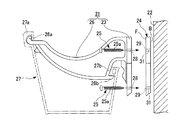
図1は、本発明の一実際形態として示した軒樋支持具21を分解して示した図である。
図1に示すように、軒樋支持具21は、アルカリ成分を含むセメント系材料又は可塑剤を含む鼻隠し板22に取り付けられ、軒樋27を装着するものであって、軒樋支持具21の取付部23と鼻隠し板22との間に後述する耐アルカリ性樹脂材料又は可塑剤を含まない樹脂材料からなるスペーサ24を介在させて取付部23、スペーサ24を螺子25により鼻隠し板22に固定するものである。
Hereinafter, embodiments of the present invention will be described with reference to the drawings.
FIG. 1 is an exploded view of an
As shown in FIG. 1, the
軒樋支持具21は、鼻隠し板22に取り付けられる上記の取付部23と、この取付部23の表面から軒先(不図示)に向かって突設された樋支持部26とを備えたものであり、樋支持部26の下方に軒樋27が装着されるものである。
The
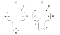
取付部23は、図2(a)に示すように、略T字状に形成された板体である。
As shown in FIG. 2A, the
取付部23の上部側板部の左右端部及び下方に延在する板部の下端部には、図1に示す螺子25を挿通させる貫通孔28が形成されている。
A through
貫通孔28は、径の寸法が螺子25の螺子部25aの径寸法と略同寸法に形成された断面円形の孔であり、図1に示すように、取付部23の表面に直交する方向に形成されている。
The through
樋支持部26は、軒先の突出方向に突出しており、軒樋27の上端縁の係止部27a、27bを係止させる耳部26a、26bを備えている。
The eaves support
スペーサ24は、図2(b)に示すように正面から見た形状が取付部23と略同形状に形成された板体であり、螺子25が螺入される壁部を形成するよう5mm〜10mm程度の厚み寸法を有している。
As shown in FIG. 2B, the
取付部23が当接するスペーサ24の前面Fには、図1、図2(b)に示すように取付部23の貫通孔28、28・・に対応するそれぞれの位置に、螺子25を螺入する際の位置決め部分となる凹所29、29・・が形成されている。
As shown in FIGS. 1 and 2B, screws 25 are screwed into the front surface F of the
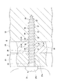
凹所29は、貫通孔28よりも小径の正円形状で、スペーサ24の厚み方向に一定寸法凹むように形成されており、図3に示すようにこの凹所29の底面30とスペーサ24の後面Bとの間は、螺子25が螺入可能な中実の壁部31とされている。
The
このように、スペーサ24には、螺子25が貫通される壁部に螺子貫通用の穴は予め形成されておらず、このスペーサ24は無穴の構成とされている。なお、凹所29の後面Bは平坦に形成されている。
As described above, the
凹所29の深さは、螺子25の先端を挿入した際に貫通孔28と凹所29の軸線を合わせることによって取付部23とスペーサ24との位置合わせが容易となるように、スペーサ24の厚み寸法に応じて、2mm〜3mm程度の寸法に設定されている。
The depth of the
上記の構成において、軒樋支持具21は、例えば耐腐蝕性、耐衝撃性、難燃性等の観点から、ポリカーボネート樹脂により形成されている。
また、スペーサ24は、前述したように耐アルカリ性樹脂材料又は可塑剤を含まない樹脂材料により形成され、例えば、硬質塩化ビニル樹脂等により形成されている。耐可塑剤性の樹脂材料としては、可塑剤を含まずかつ可塑剤を侵入させ難い樹脂であることがより好ましい。
In the above configuration, the eaves support 21 is formed of a polycarbonate resin from the viewpoint of, for example, corrosion resistance, impact resistance, flame retardancy, and the like.
The
次に、上記の軒樋支持具21の施工方法について説明する。
鼻隠し板22に対し軒樋支持具21を取り付けるには、図1に示すように、鼻隠し板22の表面の定められた位置に、凹所29が取付部23側に開口するようにスペーサ24を配置し、該スペーサ24の前面Fに軒樋支持具21の取付部23を配置しスペーサ24の凹所29を貫通孔28から視認して位置合わせする。
Next, the construction method of the eaves
In order to attach the eaves support 21 to the
そして、螺子25を取付部23の貫通孔28から挿通し、螺子25の先端を凹所29に当接させる。この際、凹所29は、貫通孔28よりも小径に形成されているので、螺子25を凹所29に嵌入して貫通孔28の軸線と合わせることによっても、貫通孔28と凹所29とを容易に位置合わせすることが可能となる。
このように貫通孔28と凹所29とを位置合わせした上で、螺子25を押圧かつ回動してスペーサ24の中実の壁部31内に螺入すると、図3に示すように、螺子25の螺子山36がスペーサ24の素材40を切り裂き、かつ該素材40を開口させつつその内部に侵入する。
Then, the
When the through
この際、螺子25により外方へ押しのけられたスペーサ24の素材40には、螺子部25aに対する反力が生じるため、該螺子山36、36・・間の螺子谷37、37・・に素材40が入り込み、螺子山36及び螺子谷37に素材40が密着した状態となる。
At this time, since the reaction force against the
螺子25を更に回動し、螺子25の螺子部25aが鼻隠し板22に進入した際には、スペーサ24の後面B側開口部付近の素材40が当該螺子25の進行に随伴して鼻隠し板22側にやや延出する。螺子25の頭部25bが取付部23の前面に当接すると、図4に示すように軒樋支持具21の鼻隠し板22への取付が完了する。
When the
上記のように、鼻隠し板22と取付部23との間に、凹所29を有するとともに螺子25を貫通させる部分に予め孔が形成されていない無穴のスペーサ24を介在させて螺子25を螺入することにより、図3に示すようにスペーサ24の素材40を螺子25の螺子部25aの表面に密着させ、鼻隠し板22と取付部23との間を遮断する。したがって、鼻隠し板22に螺子25を螺入することにより生成されるアルカリ成分を含むセメント系材料又は可塑剤を含む切粉が、スペーサ24に形成された孔38を通って取付部23に形成された貫通孔28内に移行し、ポリカーボネートにより形成された取付部23に付着することによってクラックが発生するのを防止することができるという効果が得られる。
As described above, the
また、螺子25の螺入時にあっては、貫通孔28に対応する位置に該貫通孔28よりも小径の凹所29が形成され、貫通孔28から凹所29の位置を確認したり、貫通孔28を挿通した螺子25の先端を凹所29に嵌入させることができるので、取付部23の貫通孔28とスペーサ24の凹所29との位置合わせが容易となるとともに、螺子25のスペーサ24への螺入が容易となる。
Further, when the
また、凹所29を形成した無穴のスペーサ24を用いて螺子25により取付部23を鼻隠し板22に取り付けるというシンプルな構造を採用し、かつ螺子25の螺入においても凹所29によって螺子25の先端を適切にガイドすることができるため、取付部23のクラックを防止し得る軒樋支持具21の取り付け作業が簡便であるという効果が得られる。
Further, a simple structure in which the
なお、凹所29は、一定寸法凹み底面30が平坦になるよう形成されているが、底面30をスペーサ24の後面Bに向かって漸次縮径させたテーパ形状としてもよい。凹所29をこのような形状とすることで、螺子25のスペーサ24への螺入がより容易となる。
The
上記の実施形態において、スペーサ24の鼻隠し板22に当接する後面Bは平坦に形成されているが、図5(a)、(b)に示すように、中実の壁部31を囲みかつ下方に連通して、鼻隠し板22の切粉や雨水を排出する溝39を形成したものであってもよい。
In the above embodiment, the rear surface B of the
溝39の形状、幅寸法、及び深さ寸法は、前記切粉や雨水を排出し得るものであれば特に限定されるものではないが、形状及び幅寸法は、スペーサ24の強度を考慮して切粉等をより排出しやすいものとし、深さ寸法は、スペーサ24の厚み寸法、凹所29の深さ寸法、及び螺子25が螺入される中実の壁部31の強度等を考慮して、1mm〜3mm程度に形成されるとよい。
The shape, width, and depth of the
このような溝39をスペーサ24の後面Bに形成することで、螺子25を鼻隠し板22に螺入する際に生成されるアルカリ成分を含むセメント系材料又は可塑剤を含む切粉を、スペーサ24の下方に排出することができ、これらの切粉の取付部23側への移行をより確実に防止することができる。
By forming such a
21 軒樋支持具
22 鼻隠し板
23 取付部
24 スペーサ
25 螺子
26 樋支持部
29 凹所
31 螺入可能な中実の壁部
36 螺子山
37 螺子谷
39 溝
40 素材
21 eaves support 22
Claims (3)
前記スペーサの前記螺子を貫通させる部分は、螺子を螺入可能な中実の壁部とされ、
前記スペーサの前記螺子を貫通させる部分には、前記取付部側に開口する凹所が形成されていることを特徴とする軒樋支持具。 A mounting portion having a through-hole through which a screw is inserted; a flange support portion protruding from the surface of the mounting portion; and a spacer disposed on the back surface of the mounting portion; An eaves support that is passed through a spacer and fixed to a nose cover plate,
The portion of the spacer through which the screw passes is a solid wall portion into which the screw can be screwed .
An eaves hook support tool , wherein a recess that opens toward the attachment portion is formed in a portion of the spacer through which the screw passes .
前記スペーサの前記螺子を貫通させる部分は、螺子を螺入可能な中実の壁部とされ、
前記スペーサの鼻隠し板に当接する面には、前記螺子の螺入時に前記鼻隠し板から生成されるセメント系材料又は可塑剤の切粉を下方へ導いて排出する溝が形成されていることを特徴とする軒樋支持具。 A mounting portion having a through-hole through which a screw is inserted; a flange support portion protruding from the surface of the mounting portion; and a spacer disposed on the back surface of the mounting portion; An eaves support that is passed through a spacer and fixed to a nose cover plate,
The portion of the spacer through which the screw passes is a solid wall portion into which the screw can be screwed.
The surface of the spacer that contacts the nasal cover plate is formed with a groove that guides and discharges cement-based material or plasticizer chips generated from the nasal cover plate when the screw is screwed in. eaves gutter support it said.
Priority Applications (1)
| Application Number | Priority Date | Filing Date | Title |
|---|---|---|---|
| JP2010072691A JP5548005B2 (en) | 2010-03-26 | 2010-03-26 | Eaves support |
Applications Claiming Priority (1)
| Application Number | Priority Date | Filing Date | Title |
|---|---|---|---|
| JP2010072691A JP5548005B2 (en) | 2010-03-26 | 2010-03-26 | Eaves support |
Publications (2)
| Publication Number | Publication Date |
|---|---|
| JP2011202464A JP2011202464A (en) | 2011-10-13 |
| JP5548005B2 true JP5548005B2 (en) | 2014-07-16 |
Family
ID=44879374
Family Applications (1)
| Application Number | Title | Priority Date | Filing Date |
|---|---|---|---|
| JP2010072691A Active JP5548005B2 (en) | 2010-03-26 | 2010-03-26 | Eaves support |
Country Status (1)
| Country | Link |
|---|---|
| JP (1) | JP5548005B2 (en) |
Families Citing this family (1)
| Publication number | Priority date | Publication date | Assignee | Title |
|---|---|---|---|---|
| JP5548006B2 (en) * | 2010-03-29 | 2014-07-16 | 積水化学工業株式会社 | Eaves support |
Family Cites Families (8)
| Publication number | Priority date | Publication date | Assignee | Title |
|---|---|---|---|---|
| JP3701718B2 (en) * | 1995-12-19 | 2005-10-05 | 積水化学工業株式会社 | Heel support |
| JPH10183903A (en) * | 1996-12-24 | 1998-07-14 | Toyo Chem Co Ltd | Gutter fixture |
| JP3417238B2 (en) * | 1996-12-28 | 2003-06-16 | タキロン株式会社 | Gutter fixture |
| JP4005860B2 (en) * | 2002-07-09 | 2007-11-14 | 積水化学工業株式会社 | Polycarbonate resin cage fitting |
| JP2006200315A (en) * | 2005-01-24 | 2006-08-03 | Matsushita Electric Works Ltd | Eaves gutter hanger |
| JP4696867B2 (en) * | 2005-11-18 | 2011-06-08 | パナソニック電工株式会社 | Heel support |
| JP2007285072A (en) * | 2006-04-20 | 2007-11-01 | Matsushita Electric Works Ltd | Gutter supporter |
| JP5117870B2 (en) * | 2008-01-28 | 2013-01-16 | パナソニック株式会社 | Eaves support |
-
2010
- 2010-03-26 JP JP2010072691A patent/JP5548005B2/en active Active
Also Published As
| Publication number | Publication date |
|---|---|
| JP2011202464A (en) | 2011-10-13 |
Similar Documents
| Publication | Publication Date | Title |
|---|---|---|
| JP5548005B2 (en) | Eaves support | |
| KR101502600B1 (en) | A strong anchor | |
| JP2007100480A (en) | Gutter mounting device | |
| JP2006241839A (en) | External wall construction structure | |
| TW200832290A (en) | Fire detecting device | |
| JP2005264609A (en) | Floor plate material | |
| KR101653137B1 (en) | Surface filler for constructing imitation marble and imitation marble constructing structure | |
| JP4168022B2 (en) | Reinforcement method of foundation mortar layer in finished outer wall structure | |
| JP4548321B2 (en) | Eaves mounting structure | |
| CN109252627A (en) | A kind of assembled architecture decorative wall panels | |
| JP2006125111A (en) | Width adjustable door | |
| KR200290213Y1 (en) | Locking device of anchor bolt | |
| JP5265938B2 (en) | Fixture | |
| EP1048383A1 (en) | Cable holder for a drill | |
| CN211940769U (en) | Nailing gun is fixed to pitch tile | |
| JP2011132777A (en) | Furring strip fixing implement and method of construction | |
| JP2011149228A (en) | Eaves gutter supporting implement and mounting structure of eaves gutter supporting implement | |
| CN216305222U (en) | Assembled dado of protecting against shock damage | |
| JP2008291572A (en) | Main rope fixing hardware and roof structure | |
| JP2006200314A (en) | Eaves gutter hanger | |
| JP2005133528A (en) | Mounting structure of roof material | |
| JP5272365B2 (en) | Eaves support mounting structure | |
| JP5836335B2 (en) | Parting and parting installation structure | |
| KR200307998Y1 (en) | tile assembly | |
| JP2005213913A (en) | Raindrop preventive structure |
Legal Events
| Date | Code | Title | Description |
|---|---|---|---|
| A621 | Written request for application examination |
Free format text: JAPANESE INTERMEDIATE CODE: A621 Effective date: 20121210 |
|
| A977 | Report on retrieval |
Free format text: JAPANESE INTERMEDIATE CODE: A971007 Effective date: 20130712 |
|
| A131 | Notification of reasons for refusal |
Free format text: JAPANESE INTERMEDIATE CODE: A131 Effective date: 20130723 |
|
| A521 | Written amendment |
Free format text: JAPANESE INTERMEDIATE CODE: A523 Effective date: 20130920 |
|
| TRDD | Decision of grant or rejection written | ||
| A01 | Written decision to grant a patent or to grant a registration (utility model) |
Free format text: JAPANESE INTERMEDIATE CODE: A01 Effective date: 20140422 |
|
| A61 | First payment of annual fees (during grant procedure) |
Free format text: JAPANESE INTERMEDIATE CODE: A61 Effective date: 20140516 |
|
| R151 | Written notification of patent or utility model registration |
Ref document number: 5548005 Country of ref document: JP Free format text: JAPANESE INTERMEDIATE CODE: R151 |