JP5543914B2 - Artificial tooth root system - Google Patents
Artificial tooth root system Download PDFInfo
- Publication number
- JP5543914B2 JP5543914B2 JP2010503350A JP2010503350A JP5543914B2 JP 5543914 B2 JP5543914 B2 JP 5543914B2 JP 2010503350 A JP2010503350 A JP 2010503350A JP 2010503350 A JP2010503350 A JP 2010503350A JP 5543914 B2 JP5543914 B2 JP 5543914B2
- Authority
- JP
- Japan
- Prior art keywords
- implant
- region
- root system
- gingival
- intraosseous
- Prior art date
- Legal status (The legal status is an assumption and is not a legal conclusion. Google has not performed a legal analysis and makes no representation as to the accuracy of the status listed.)
- Expired - Fee Related
Links
Images


Classifications
-
- A—HUMAN NECESSITIES
- A61—MEDICAL OR VETERINARY SCIENCE; HYGIENE
- A61C—DENTISTRY; APPARATUS OR METHODS FOR ORAL OR DENTAL HYGIENE
- A61C8/00—Means to be fixed to the jaw-bone for consolidating natural teeth or for fixing dental prostheses thereon; Dental implants; Implanting tools
- A61C8/0048—Connecting the upper structure to the implant, e.g. bridging bars
- A61C8/0075—Implant heads specially designed for receiving an upper structure
-
- A—HUMAN NECESSITIES
- A61—MEDICAL OR VETERINARY SCIENCE; HYGIENE
- A61C—DENTISTRY; APPARATUS OR METHODS FOR ORAL OR DENTAL HYGIENE
- A61C8/00—Means to be fixed to the jaw-bone for consolidating natural teeth or for fixing dental prostheses thereon; Dental implants; Implanting tools
- A61C8/0018—Means to be fixed to the jaw-bone for consolidating natural teeth or for fixing dental prostheses thereon; Dental implants; Implanting tools characterised by the shape
-
- A—HUMAN NECESSITIES
- A61—MEDICAL OR VETERINARY SCIENCE; HYGIENE
- A61C—DENTISTRY; APPARATUS OR METHODS FOR ORAL OR DENTAL HYGIENE
- A61C8/00—Means to be fixed to the jaw-bone for consolidating natural teeth or for fixing dental prostheses thereon; Dental implants; Implanting tools
- A61C8/0048—Connecting the upper structure to the implant, e.g. bridging bars
- A61C8/005—Connecting devices for joining an upper structure with an implant member, e.g. spacers
-
- A—HUMAN NECESSITIES
- A61—MEDICAL OR VETERINARY SCIENCE; HYGIENE
- A61C—DENTISTRY; APPARATUS OR METHODS FOR ORAL OR DENTAL HYGIENE
- A61C8/00—Means to be fixed to the jaw-bone for consolidating natural teeth or for fixing dental prostheses thereon; Dental implants; Implanting tools
- A61C8/0048—Connecting the upper structure to the implant, e.g. bridging bars
- A61C8/0077—Connecting the upper structure to the implant, e.g. bridging bars with shape following the gingival surface or the bone surface
-
- A—HUMAN NECESSITIES
- A61—MEDICAL OR VETERINARY SCIENCE; HYGIENE
- A61K—PREPARATIONS FOR MEDICAL, DENTAL OR TOILETRY PURPOSES
- A61K6/00—Preparations for dentistry
- A61K6/80—Preparations for artificial teeth, for filling teeth or for capping teeth
- A61K6/802—Preparations for artificial teeth, for filling teeth or for capping teeth comprising ceramics
- A61K6/818—Preparations for artificial teeth, for filling teeth or for capping teeth comprising ceramics comprising zirconium oxide
-
- A—HUMAN NECESSITIES
- A61—MEDICAL OR VETERINARY SCIENCE; HYGIENE
- A61K—PREPARATIONS FOR MEDICAL, DENTAL OR TOILETRY PURPOSES
- A61K6/00—Preparations for dentistry
- A61K6/80—Preparations for artificial teeth, for filling teeth or for capping teeth
- A61K6/84—Preparations for artificial teeth, for filling teeth or for capping teeth comprising metals or alloys
Description
本発明は、インプラントと上部構造から成る人工歯根システムに関する。 The present invention relates to an artificial dental root system comprising an implant and a superstructure.
ドイツでは、毎年約70万回人工義歯が埋め込まれている。それは、通常人工歯根(歯根インプラント)と、接続部材(所謂アバットメント)と、例えば、クラウンやブリッジなどの上部構造との三つの要素から構成されている。 In Germany, about 700,000 artificial dentures are implanted every year. It is usually composed of three elements: an artificial tooth root (root implant), a connecting member (so-called abutment), and an upper structure such as a crown or a bridge.
人工義歯を埋め込むためには、先ずは失った歯の残骸、例えば、その歯根などを完全に取り除かなければならない。次に、顎に穴を開けるが、或いは顎にねじ山を切って歯根インプラントを食い込ませる、或いはねじ込ませている。そのため、インプラントは、大抵円筒体又は円錐体の形状で作られている。顎に埋め込んだ後3〜6カ月間は、インプラントが根付くように、即ち、顎と固く癒合するようにしなければならない。その間、インプラントに機械的な負荷をかけてはならない。根付いた後は、通常アバットメントをインプラントとねじ止め又は接着して、次に、アバットメントに上部構造を取り付けている。アバットメントは、アバットメントに上部構造を機械的に固定する役割を果たす、所謂取付ピンを有する。 In order to embed an artificial denture, it is first necessary to completely remove lost tooth debris, such as its roots. Next, a hole is drilled in the jaw, or a thread is cut into the jaw to bite or screw the root implant. Therefore, the implant is usually made in the shape of a cylinder or a cone. For 3 to 6 months after implantation in the jaw, the implant must be rooted, i.e. tightly united with the jaw. During that time, the implant must not be mechanically loaded. Once rooted, the abutment is usually screwed or glued to the implant and then the superstructure is attached to the abutment. The abutment has so-called mounting pins that serve to mechanically fix the superstructure to the abutment.
しかし、このような構造は、幾つかの欠点を持っている。構造上の制約から、インプラントとアバットメントの間に細菌を繁殖させる隙間が生じる。骨の方向に向かってアバットメントに沿った歯肉ポケットが、細菌に対して開いた侵入箇所を構成している。細菌が分泌物として生成する酸が、隙間領域におけるインプラント/アバットメントと歯肉の癒合を妨げている。更に、顎の骨は、常に生物学的な幅に対応して再生しており、多くの場合、歯肉の炎症と更なる骨の崩壊及びそれに続く歯肉の更なる欠損が起こる。その結果、細菌の巣くうポケットが発生し、患者自身がそこにアクセスできないので、費用がかかる、細菌の巣くうポケットの掃除には、患者にとって面倒な歯医者による治療措置が必要となり、通常インプラントを損なうことともなる。更に、ポケットの掃除を行うことの欠点は、それによって、アバットメントとインプラント間の隙間の上の領域において、歯肉がアバットメントと癒合することができなくなることである。その結果、その間に避けられない歯肉ポケットへのアクセスの悪さが、その領域における正常な口腔衛生を妨害して、そのため患者がインプラントを非常に不快に感じることとなる。そのような間に、健康な組織の炎症と破壊が一層進行する。 However, such a structure has several drawbacks. Due to structural constraints, there is a gap for the propagation of bacteria between the implant and the abutment. Gingival pockets along the abutment in the direction of the bone constitute an entry site that is open to bacteria. The acids produced by the bacteria as secretions prevent the fusion of the implant / abutment and gingiva in the interstitial area. In addition, the jaw bone is constantly regenerating in response to biological width, often resulting in gingival inflammation and further bone collapse followed by further gingival loss. As a result, a bacteria nest pocket is created, and the patient himself cannot access it, which is expensive, and cleaning the bacteria nest pocket requires a dentist's troublesome treatment and usually damages the implant. It also becomes. Furthermore, a disadvantage of cleaning the pocket is that it prevents the gum from healing with the abutment in the region above the gap between the abutment and the implant. As a result, inevitable access to the gingival pockets in the meantime interferes with normal oral hygiene in the area, which makes the patient feel very uncomfortable. In the meantime, inflammation and destruction of healthy tissue progresses further.
別の欠点は、歯根インプラントとアバットメント間のねじ接続部が大きな機械的な負荷に曝されることである。それによって、通常インプラントとアバットメント間の僅かな動きを生じさせ、特に、ねじを破壊して、高い費用を発生させることとなる。更に、ねじ接続部をセメント又は接着剤で固定した場合、漏れ出た材料が歯肉を刺激する可能性が有る。 Another disadvantage is that the screw connection between the root implant and the abutment is exposed to a large mechanical load. This usually results in a slight movement between the implant and the abutment, in particular, breaking the screw and generating high costs. Furthermore, if the screw connection is secured with cement or adhesive, the leaked material can irritate the gums.
歯根インプラントは、通常様々なステップの大きさで事前に製作された回転対称の標準的なインプラントとして実現されている。医療用器具の消毒に関するEC規則のために、埋入を実施する歯科医は、その間事前に製作されたインプラントを個別に調整することができない。そのため、ステップが予め規定されているので、多くの場合埋め込むインプラントの大きさに関して妥協しなければならない。顎堤にインプラント基底部を開削することによって生じる骨の離開にインプラントを適合させることができないことも欠点である。その結果、そのようなインプラントは、個別に適合できれば実現可能である場合よりも大幅に小さい骨の接触面とそれに関連した悪い係止を提供することとなる。更に、歯肉の解剖学的な軟部状況が考慮されていない。そのため、美しさと清潔さが大きく制約されている。そのような補償されない骨の離開は、通常望ましくない歯肉ポケットを形成する原因となる。最後に、多くの大きさと形状の事前に製作された標準的なインプラントを支持しなければならないので、その姿勢を維持するために大きな費用が発生する。 Root implants are usually realized as rotationally symmetric standard implants prefabricated with various step sizes. Due to EC regulations regarding the disinfection of medical instruments, dentists performing implants cannot individually adjust prefabricated implants during that time. Therefore, since the steps are predefined, often a compromise must be made regarding the size of the implant to be implanted. It is also a drawback that the implant cannot be adapted to the bone dehiscence that occurs by cutting the base of the implant into the ridge. As a result, such implants provide significantly smaller bone contact surfaces and associated poor locking than would be possible if individually adapted. Furthermore, the anatomical soft part situation of the gingiva is not considered. Therefore, beauty and cleanliness are greatly restricted. Such uncompensated bone degeneration usually causes undesirable gingival pockets. Finally, many pre-manufactured standard implants of many sizes and shapes must be supported, resulting in high costs for maintaining that posture.
取付ピンを用いてアバットメントに上位構造を固定することは、力の分散と梃子比を不利にし、それによって、破壊する虞が増大する。更に、取付ピンをねじ止めした場合も、明白な破壊的微動が起こる。 Fixing the upper structure to the abutment using the mounting pin detracts from the force distribution and the lever ratio, thereby increasing the risk of breakage. Further, when the mounting pin is screwed, an obvious destructive tremor occurs.
近年インプラント技術において、著しい進歩が達成されており、多くの開発が前述した問題の解決に向けられている。 In recent years, significant progress has been achieved in implant technology, and many developments have been directed to solving the aforementioned problems.
即ち、特許文献1では、骨内インプラント材との接触箇所のアバットメント上に直接めっきして可塑的に成形可能な金属層を被せることが提案されている。それによって、アバットメントとインプラントの間に細菌を繁殖させる隙間ができることを防止している。同様に、特許文献2では、インプラントとインプラント上部構造の間に金の板を挿入することが提案されている。これら二つの解決策は、確かに隙間を最小限にするが、チタン、金、歯肉及び唾液間の接触が刺激性の化学反応を引き起こすことが予想される。更に、細菌の繁殖を防止することはできない。
That is,
特許文献3には、軸方向に貫通する穴を備えたアバットメントが記載されている。そのようなアバットメントをインプラントとねじ止めして、そのねじ止め部分を更にセメントで固着させるものと規定している。この貫通穴は、固着させる間に余分なセメントを貫通穴に押し出して、インプラントの平坦な頭部上に集める役割を果たしている。そのような頭部からセメントを簡単に取り出すことができる。そうすることによって、別の箇所に流れ出たセメントによる歯肉の炎症を防止すること可能である。
特許文献4は、接続ボルトを介して、根付いたインプラントに取り付けることができる個別的な義歯の製作方法を開示している。義歯を製作する際の負担を軽減するために、義歯を一体的に製作することを提案している。そうすることによって、別個のアバットメントを省略することができる。そのため、明らかに簡略化が実現されるが、細菌を繁殖させる隙間の問題は依然として残っている。 Patent document 4 is disclosing the manufacturing method of the individual denture which can be attached to a rooted implant via a connection bolt. In order to reduce the burden when manufacturing dentures, it is proposed to manufacture dentures integrally. By doing so, a separate abutment can be omitted. So obviously simplification is realized, but the problem of gaps for breeding bacteria still remains.
特許文献5では、円錐形の胴体部分と分岐する頭部部分から成る歯根インプラントが提案されており、二つの部分は、一体的に構成されるか、或いは連結される部分として実現されている。更に、この人工歯根システムは、歯根インプラントに適合したアバットメントを有し、それは、義歯及び/又はクラウンを支持する役割を果たしている。このアバットメントは、ねじを用いて歯根インプラントの円錐形の胴体部分にねじ込まれる。
胴体部分と頭部部分の一体的又は統一的な実現形態によって、確かに骨内領域における僅かな隙間は防止されているが、歯肉領域における胴体部分/頭部部分とアバットメント間の細菌を繁殖させる隙間の形成は防止されない。 An integral or unified realization of the torso and the head part certainly prevents slight gaps in the intraosseous area, but breeds bacteria between the torso / head part and the abutment in the gingival area The formation of gaps to be caused is not prevented.
特許文献6には、インプラントとアバットメントから成る歯科用支持構造が記載されている。アバットメントの上端とそれに対応するそこに固定されるクラウンの下端は、歯肉から出た時に、それに対応して突き出る輪郭及び取り替えた歯の大きさに合っている。
アバットメントとクラウン間の境界を歯肉の推移に合わせることによって、回転対称な解決策と比べて美的及び機能的な利点が得られている。しかし、アバットメントとクラウン間の境界は、正確に歯肉の縁の高さに、或いはそれ以上に有る。歯肉は、通常時間の経過と共に再生するので、数時間後に金属製のアバットメントが歯肉の縁より上に到達して、見えるようになることを防止することはできない。 By matching the boundary between the abutment and the crown to the transition of the gingiva, aesthetic and functional advantages are obtained compared to the rotationally symmetric solution. However, the boundary between the abutment and the crown is exactly at or above the height of the gingival margin. Since the gums usually regenerate with time, it is not possible to prevent the metal abutment from reaching the gum edge and becoming visible after several hours.
従来技術では、前述した義歯の代わりに、インプラントの骨内部分と、アバットメントと、場合によっては、取付ピンとが一つの部材で作られるか、或いは少なくとも継目無く組み上げられている回転対称なインプラントを使用することが一般的である(特許文献7参照)。 In the prior art, instead of the above-mentioned denture, a rotationally symmetric implant in which the intra-osseous part of the implant, the abutment, and in some cases, the mounting pin are made of one member or at least seamlessly assembled. It is common to use (refer patent document 7).
それによると、そのようなインプラントは、顎の骨と歯肉間の境界領域における隙間が当初から防止されるとともに、僅かな動きも阻止されているので、歯肉がインプラントと問題無く癒合することができる。それにも関わらず、そのようなインプラントは、複数の根本的な理由から受け入れられていない。一つの理由は、取付ピンが構造上の制約から口腔内に突き出ることである。そのため、必然的に癒合の間インプラントに機械的な負荷が加わり、その結果頻繁に埋入が失敗することとなる。別の理由は、インプラントの回転対称性のために、インプラントがクラウンから歯肉への遷移領域で見えたままとなり、それは、特に、チタンを使用している場合、美的理由から受け入れられない。インプラントの形状が、顎の骨の顎堤に穴を開けることによって起こる前庭/口前庭側及び口蓋/舌側における骨の離開を考慮していないことが特に不利である。 According to it, such an implant prevents the gap in the boundary area between jaw bone and gingiva from the beginning and also prevents slight movement, so that the gingiva can be united with the implant without any problems. . Nevertheless, such implants are unacceptable for several fundamental reasons. One reason is that the mounting pins protrude into the oral cavity due to structural constraints. This inevitably places a mechanical load on the implant during healing, resulting in frequent failure of the implant. Another reason is that due to the rotational symmetry of the implant, the implant remains visible in the transition region from crown to gingiva, which is unacceptable for aesthetic reasons, especially when using titanium. It is particularly disadvantageous that the shape of the implant does not take into account the vestibular / oral vestibular and palatal / lingual bone dislocations that occur by puncturing the jawbone ridge.
本発明の課題は、従来技術の欠点を取り除くことである。特に、歯肉領域における歯肉との良好な癒合を可能にするとともに、歯の構造と顎の骨との機械的に安定した長続きする結合を保証する、美的効果を奏する、歯肉の縁において見えない人工歯根システムを実現することである。 The object of the present invention is to eliminate the disadvantages of the prior art. In particular, an artificial that is invisible at the gingival rim, providing an aesthetic effect that allows a good fusion with the gingiva in the gingival area and ensures a mechanically stable and long-lasting connection between the tooth structure and the jaw bone It is to realize a root system.
本課題は、本発明による請求項1の特徴部に記載された特徴によって解決され、別の有利な実施形態は、請求項2〜13から明らかとなる。
This problem is solved by the features described in the characterizing part of
インプラントとその上に取り付けられる上部構造とから成る人工歯根システムを出発点とする。このインプラントは、典型的にはハニカム形又はねじ山形の構造を持つ下方の骨内領域と、上に向かって拡がって行く、表面が粗い上方の骨内領域と、壁面が滑らかな歯肉移行領域と、歯肉に移行するインプラント頭部とから構成される。これら全ての領域は、互いに縫目無く及び隙間無く繋がっている。 The starting point is an artificial dental root system consisting of an implant and a superstructure mounted thereon. The implant typically has a lower intraosseous region with a honeycomb or thread-like structure, an upper intraosseous region with a rough surface that extends upward, and a gingival transition region with a smooth wall. And the implant head that transitions to the gingiva. All these regions are connected to each other without a seam and without a gap.
下方の骨内領域は、通常回転対称な円筒体/円錐体、回転対称な円筒体/円錐体の組合せ、回転対称な階段状の円筒体/円錐体、或いは回転対称な階段状の円筒体/円錐体の組合せの形で形成されている。有利には、顎の骨との良好な癒合を実現するために周知の頂点が尖ったハニカム構造を持つ形に形成される。 The lower intraosseous region is usually a rotationally symmetric cylinder / cone, a rotationally symmetric cylinder / cone combination, a rotationally symmetric stepped cylinder / cone, or a rotationally symmetric stepped cylinder / It is formed in the form of a conical combination. Advantageously, it is formed into a well-known pointed honeycomb structure in order to achieve a good fusion with the jaw bone.
本発明では、上方の骨内領域は、前庭/口前庭の方向と口蓋/舌の方向に、それぞれ短縮部分を有する。それに対応して、上方の骨内領域は、その顎堤の側面と接する箇所がより高く実現されている。そうすることによって、インプラントが、正確に患者特有の顎堤と合致して、その結果インプラントが、インプラント基底部の穴によって起こる骨の離開を完全に考慮することとなる。上方の骨内領域が上に向かって拡がって行くことによって、埋入時に、より大きな骨との接触面とそのため顎の骨内におけるインプラントの良好な保持が実現される。 In the present invention, the upper intraosseous region has shortened portions in the vestibule / mouth vestibule direction and palate / tongue direction, respectively. Correspondingly, the upper intra-osseous region is realized at a higher location in contact with the side surface of the jaw ridge. By doing so, the implant will exactly match the patient-specific jaw crest, so that the implant will fully account for bone dehiscence caused by the implant base hole. By expanding the upper intraosseous region upwards, a better retention of the implant in the jaw bone is achieved during implantation, thus making contact with the larger bone.
滑らかな歯肉移行領域は、患者の歯肉の窩洞に応じて形成される。そのような解剖学的な形状に対応して、歯肉移行領域の各縦断面及び各横断面の形状は、当該の断面の前又は後に有る縦断面又は横断面の形状と異なることとなる。 A smooth gingival transition region is formed depending on the cavity of the patient's gingiva. Corresponding to such an anatomical shape, the shape of each longitudinal section and each transverse section of the gingival transition region will be different from the shape of the longitudinal section or the transverse section before or after the relevant section.
歯肉移行領域は、上方に関して、個別に形成されるとともに、高さ、幅、深さが異なる形で三次元的に構成された、歯肉に移行するインプラント頭部によって画定されている、即ち、インプラント頭部がインプラントの「カバー面」を形成している。同様に、その各縦断面及び各横断面の形状は、当該の断面の前又は後に有る縦断面又は横断面の形状と異なっている。この場合、そのようにして歯肉移行領域と歯肉に移行するインプラント頭部によって形成された周囲を巡る周縁部は、プレパラートの境界面と一致し、埋入の実施後に歯肉の縁の僅かに下、典型的には、1mm下を延びるように形成される。 The gingival transition region is defined by an implant head that transitions to the gingiva, which is individually formed with respect to the upper side and is three-dimensionally configured in different shapes of height, width and depth, ie, an implant The head forms the “cover surface” of the implant. Similarly, the shape of each longitudinal section and each transverse section is different from the shape of the longitudinal section or the transverse section before or after the relevant section. In this case, the peripheral edge around the periphery formed by the gingival transition region and the implant head that transitions to the gingiva coincides with the preparation interface, and is slightly below the gingival margin after implantation, Typically, it is formed to extend below 1 mm.
歯肉に移行するインプラント頭部は、その中央に平坦な領域を有する。それは、急峻に低下する部分領域によって取り囲まれており、その急峻に低下する部分領域は、平坦な部分領域を歯肉移行領域と繋いでいる。この場合、インプラント頭部の平坦な領域によって形成された台地状部分の高さは、それが正確に隣接面方向に対して上方の歯肉境界の高さに位置するように配置される。 The implant head that transitions to the gingiva has a flat region in the center. It is surrounded by a steeply lowered partial region that connects the flat partial region to the gingival transition region. In this case, the height of the plateau formed by the flat region of the implant head is arranged so that it is exactly at the height of the upper gingival boundary with respect to the adjacent surface direction.
上方の骨内領域を患者特有の顎堤に適合させているために、インプラント頭部の急峻な部分領域の前庭/口前庭の方向及び口蓋/舌の方向における長さと勾配が、それ以外の方向における長さと勾配よりも長くかつ急峻になっている。 Because the upper intraosseous region is adapted to the patient's unique jaw crest, the length and gradient in the vestibular / mouth vestibular and palatal / lingual directions of the steep partial region of the implant head are otherwise It is longer and steeper than the length and slope at.
インプラント頭部の全面上には、下側がインプラント頭部の形状と合致した上部構造が接着される、或いはセメントで固着される。そのような接合は、インプラントと上部構造の間に作用する力の大部分を吸収する。更に、側方へのずれの防止と一層の機械的な安定を実現するために、取付ピンが、インプラントの歯肉移行領域内におけるプレパラート面のほぼ中心にねじ込まれるとともに、その別の側が上部構造と接続される。取付ピンの底面は、歯肉に移行するインプラント頭部の平坦な部分上に置かれて、力を補償する傾斜防止器具及び力を吸収して伝達する部分として機能する。 On the entire surface of the implant head, an upper structure whose lower side matches the shape of the implant head is bonded or fixed with cement. Such a bond absorbs most of the forces acting between the implant and the superstructure. Furthermore, in order to prevent lateral displacement and further mechanical stability, the mounting pin is screwed to approximately the center of the preparation surface in the gingival transition region of the implant and its other side is connected to the superstructure. Connected. The bottom surface of the mounting pin is placed on a flat portion of the implant head that transitions to the gingiva and functions as an anti-tilt device that compensates for the force and a portion that absorbs and transmits the force.
インプラントは、有利には、一つの部材(未加工品)から作られる。この場合、医学的に耐久性の有る材料として、チタン、酸化ジルコニウム並びに人工歯根に適した全ての材料が考えられる。 The implant is advantageously made from one piece (raw). In this case, all materials suitable for titanium, zirconium oxide, and artificial tooth roots can be considered as medically durable materials.
本発明による人工歯根システムは、従来用いられてきたシステムと比べて多くの利点を有する。 The artificial dental root system according to the present invention has many advantages over the systems that have been used conventionally.
本インプラントシステムの重要な利点は、それがアバットメント無しに実現されており、そのため、顎の骨と歯肉間の境界領域における細菌を繁殖させる隙間が当初から防止されていることである。プレパラート境界面が歯肉の縁の僅かに下に有るので、患者がそれにアクセスすることができ、それを快適に清掃することができる。歯科医によってポケットを除去してもらう必要性が無くなる。更に、インプラントは、骨内領域が顎の骨に根付く段階の間に早くも歯肉移行領域において同時に歯肉と癒合することができる。それは、歯肉が埋入のための措置によって依然として「新鮮かつ血を流す」状態にある場合に特に有利である。ポケットを除去する必要性が無くなるので、インプラントに対して生長する歯肉を後で再び取り去る必要もない。その結果、患者にとって面倒な高くつく回復措置が避けられるとともに、更に、従来と異なり歯肉ポケットが形成されず、その領域における口腔衛生上の措置を簡単かつ特に確実に実施できるので、患者はインプラントを全く異物として感じなくなる。 An important advantage of the present implant system is that it is realized without an abutment, so that gaps that allow bacteria to propagate in the border region between the jaw bone and the gingiva are prevented from the outset. Since the preparation interface is slightly below the gingival margin, the patient can access it and clean it comfortably. Eliminates the need for the dentist to remove the pocket. Furthermore, the implant can simultaneously fuse with the gingiva in the gingival transition region as early as the stage during which the intraosseous region takes root in the jaw bone. It is particularly advantageous when the gingiva is still “fresh and shed” by the measures for placement. Since there is no need to remove the pockets, there is no need to later remove again the gingiva that grows against the implant. As a result, troublesome and expensive recovery measures for the patient are avoided, and moreover, unlike the conventional case, a gingival pocket is not formed, and oral hygiene measures in that area can be performed easily and particularly reliably. It doesn't feel as a foreign object at all.
インプラントとアバットメント間のねじ止めを無くすことによって、多くの場合にねじの壊れる原因、しかも顎の骨の周囲を巡る部分を退化させる原因となり、その結果顎の骨の上に有る、骨によって均一に支えられている安定させるための歯肉を退化させる原因ともなる、さもなければインプラントとアバットメント間で構造的な制約から起こってしまう僅かな動きが防止される。 Eliminating the screwing between the implant and the abutment often causes the screw to break and also causes the part around the jaw bone to degenerate, resulting in a uniform bone over the jaw bone The slight movement that would otherwise cause degeneration of the stabilizing gingiva, otherwise caused by structural constraints between the implant and the abutment, is prevented.
下方の骨内領域の大きさと形状を患者の解剖学的な構造に個別に合致させることによって、骨との最大限の接触面が実現される。同様に、上に向かって拡がって行く形状と、上方の骨内領域と顎の骨の顎堤との正確な適合と、それらに関連したインプラント基底部の穴によって起こる骨の離開に対する完全な適合とによって、顎の骨の上方領域における大きな設置面が保証される。インプラントの骨内領域は、その構造を持った表面又は粗い表面のために、顎の骨と迅速かつ確実に癒合することができる。 By individually matching the size and shape of the underlying intra-osseous area to the patient's anatomy, maximum contact with the bone is achieved. Similarly, the exact shape of the upwardly expanding shape, the precise fit between the upper intraosseous region and the maxillary ridge of the jaw bone, and the perfect fit against the bone dehiscence caused by the associated implant base hole This ensures a large installation surface in the upper region of the jaw bone. The intraosseous region of the implant can heal quickly and reliably with the jaw bone because of its structured or rough surface.
本人工歯根システムの単一の接続箇所は、一方では患者自身によって清掃できるが、他方では根付く段階の間に、例えば、別の歯との機械的な接触による機械的な負荷を相当程度防止できるように選定される。 The single connection point of the artificial dental root system can be cleaned on the one hand by the patient himself, but on the other hand during the rooting phase, for example, to a great extent prevent mechanical loads due to mechanical contact with another tooth, for example. Is selected as follows.
インプラントと上部構造間の機械的な接合が主にアバットメント/取付ピンによって実現されていた、これまで使用されてきた人工歯根システムと異なり、本発明のシステムでは、インプラント頭部と上部構造の下側の間の接着剤又はセメントによって形成される、大きな面による材料レベルでの固い接合部が機械的な負荷を吸収する。ここで使用される補綴ポストは、支える機能を有し、上部構造を挿入する間に横にずれることを防止するとともに、歯肉に移行するインプラント頭部の平坦な部分上に基礎を置いていることによって、力が横から加わった場合に、その力を吸収する要素として機能する。 Unlike previously used artificial dental root systems, where mechanical joints between the implant and the superstructure have been achieved primarily by abutments / mounting pins, the system of the present invention allows the implant head and superstructure to be A solid joint at the material level with large surfaces, formed by adhesive or cement between the sides, absorbs the mechanical load. The prosthetic post used here has a supporting function, prevents lateral displacement during insertion of the superstructure, and lies on the flat part of the implant head that transitions to the gingiva Therefore, when force is applied from the side, it functions as an element that absorbs the force.
また、本発明では、人工歯根システムの下方と上方の骨内領域を回転対称でない形状で構成しており、そのような幾何学的な形状は、対称軸がその垂直方向に対して互いに平行にずれているか、或いは少なくとも上方の骨内領域内で交差するように互いに傾斜している、少なくとも二つの回転対称な幾何学的物体の重なり合う部分と一致するものと規定している。これらの幾何学的物体は、常に少なくとも上方の骨内領域内で重なり合い、その結果そこには、回転対称でない閉じた横断面が形成されている。下方の骨内領域は、歯根の形状に構成されるか、或いは同様の閉じた横断面を持つことができる。 In the present invention, the lower and upper bone regions of the artificial dental root system are configured in a shape that is not rotationally symmetric, and such a geometric shape is such that the symmetry axis is parallel to the vertical direction. It is defined as coincident with overlapping portions of at least two rotationally symmetric geometric objects that are offset or inclined at least so as to intersect within the upper bone region. These geometric objects always overlap at least in the upper intraosseous region, so that there is a closed cross section that is not rotationally symmetric. The lower intraosseous region can be configured in the shape of a tooth root or have a similar closed cross section.
骨内領域の回転対称でない形状のために、埋め込まれたインプラントは、顎の骨と共に、比較的大きな回転負荷及び傾斜負荷に耐える支持体を構成する。更に、そのような構成によって、顎の骨に対するインプラントの確固たる位置決めと固定が可能となる。 Due to the non-rotationally symmetric shape of the intraosseous region, the implanted implant together with the jaw bone constitutes a support that can withstand relatively large rotational and tilt loads. Furthermore, such a configuration allows for firm positioning and fixation of the implant relative to the jaw bone.
閉じた横断面を持つ上方と下方の骨内領域の部分に関して、有利には、先端が円錐形の円筒体の幾何学的物体の重なり合う部分に一致する幾何学的な形状が選定される。これらの円筒体は、同じ半径を持つことも、異なる半径を持つこともできる。これらの物体の対称軸は、少なくとも上方の骨内領域内で交差するように配置される。対称軸相互の傾斜角は、通常1°〜45°である。 For portions of the upper and lower intraosseous regions with closed cross-sections, a geometric shape is advantageously chosen that corresponds to the overlapping portion of the conical cylindrical geometric object at the tip. These cylinders can have the same radius or different radii. The symmetry axes of these objects are arranged so as to intersect at least in the upper bone region. The inclination angle between the symmetry axes is usually 1 ° to 45 °.
下方の骨内領域の歯根形状に形成された部分に関して、有利には、平行に配置された円錐形の幾何学的物体の重なり合う部分に一致する幾何学的な形状が選定される。 With respect to the part of the lower endosteal region formed in the root shape, a geometric shape is advantageously chosen that corresponds to the overlapping part of the conical geometric objects arranged in parallel.
人工歯根システムの製作方法及びその患者の顎又は口腔への取付方法は、次の工程を有する。 A method for manufacturing an artificial dental root system and a method for attaching the artificial tooth root system to a patient's jaw or oral cavity include the following steps.
第一に、顎の形状と治療する患者の歯肉の形状をCT(コンピュータ断層撮影)、DVT(デジタルボリューム断層撮影)又はそれに代わるOPGで撮影する。 First, the shape of the jaw and the shape of the patient's gingiva to be treated are imaged by CT (computer tomography), DVT (digital volume tomography), or OPG instead.
先ずはインプラント全体を製作するための未加工品に対して、検出した解剖学的な診断データにもとづき、CAD/CAM技術を用いて骨内部分を作る。この部分は、回転対称な円筒体/円錐体、回転対称な円筒体/円錐体の組合せ、回転対称な階段状の円筒体/円錐体、或いは回転対称な階段状の円筒体/円錐体の組合せの形状で作られる。骨への良好な根付きを可能とするために、骨内部分には構造が設けられている。この場合、有利には、実証済みの頂点が尖ったハニカム構造が選定される。 First, an intra-bone part is made using a CAD / CAM technique based on the detected anatomical diagnosis data for a raw product for manufacturing the entire implant. This part can be a rotationally symmetric cylinder / cone, a rotationally symmetric cylinder / cone combination, a rotationally symmetric stepped cylinder / cone, or a rotationally symmetric stepped cylinder / cone combination Made in the shape of In order to allow good rooting in the bone, a structure is provided in the intra-bone part. In this case, it is advantageous to select a honeycomb structure with pointed vertices.
それに続いて、解剖学的な診断データに応じて、骨内部分に隣接させて、CAD/CAMによって更に別の骨内領域を作る。この場合、顎堤に個別に適合させるために、前庭/口前庭の方向に向かって、より大きい、かつ口蓋/舌の方向に向かって、より小さい短縮部分を作る。そのようにして、インプラントの形状が、その後のインプラント基底部の開削によって起こる骨の離開を完全に考慮したものとなる。 Subsequently, another intraosseous region is created by CAD / CAM, adjacent to the intraosseous portion, depending on the anatomical diagnostic data. In this case, a smaller shortening is made in the direction of the vestibule / mouth vestibule, larger and smaller in the direction of the palate / tongue, in order to adapt individually to the ridge. In that way, the shape of the implant fully takes into account the dehiscence of the bone caused by the subsequent excision of the implant base.
その後、検出した解剖学的な診断データにもとづき、手動による処理又は場合によってはCAD/CAMによって、歯肉移行領域を作る。個別の整形によって、如何なる場合でも、歯肉移行領域の各縦断面及び各横断面の形状が、当該の断面の前又は後に有る縦断面又は横断面の形状と異なることとなる。 Thereafter, based on the detected anatomical diagnostic data, a gingival transition region is created by manual processing or possibly CAD / CAM. Due to the individual shaping, in any case, the shape of each longitudinal section and each transverse section of the gingival transition region is different from the shape of the longitudinal section or the transverse section before or after the relevant section.
それに続いて、手動による処理又は場合によってはCAD/CAMによって、歯肉移行領域の上方の境界を画定する、歯肉に移行するインプラント頭部を作る。インプラント頭部は、歯肉における窩洞の形状及び周縁部の推移の診断測定データにもとづき、埋入後のプレパラート面及び歯肉移行領域によって形成される縁が歯肉の縁の下を延びるように作られる。インプラント頭部のほぼ中央には、平坦な部分領域が形成され、それを取り囲んで急峻に低下する部分領域が形成される。この急峻な部分領域によって、平坦な部分領域と歯肉移行領域が互いに繋がれている。更に、補綴ポストを収容するためのねじ孔をインプラント頭部の平坦な部分領域に設ける。 Subsequently, manual treatment or possibly CAD / CAM creates an implant head that transitions to the gingiva that defines the upper boundary of the gingival transition region. The implant head is made so that the edge formed by the prepared preparation surface and the gingival transition area extends below the gingival edge based on the diagnostic measurement data of the cavity shape and peripheral edge transition in the gingiva. A flat partial region is formed approximately at the center of the implant head, and a partial region is formed that surrounds it and rapidly decreases. By this steep partial region, the flat partial region and the gingival transition region are connected to each other. Furthermore, a screw hole for receiving the prosthetic post is provided in the flat partial region of the implant head.
次の工程では、歯肉移行領域と歯肉に移行するインプラント頭部を滑らかにする。この滑らかにすることは、有利には、手動による機械的な研磨又はCAD/CAMによって行われる。その後、インプラントの骨内領域全体の表面を粗くすることが、好適な手法で行われる。 In the next step, the gingival transition region and the implant head that transitions to the gingiva are smoothed. This smoothing is advantageously done by manual mechanical polishing or CAD / CAM. Thereafter, roughening the surface of the entire intra-osseous region of the implant is performed in a suitable manner.
次の工程では、穴を開けるインプラント基底部の直径の段階的な変更が行われる。そのために、第一に、相応のドリルを用いて、約1mmから始めて、インプラントの下方の骨内領域よりも0.5mm小さい直径となるまで穴の直径を小さくして行くように、顎の骨にインプラント基底部の穴を開ける。次に、その穴にもとづき、或いは別の試験方法によって、骨の硬さ又は質を検出する。骨の質と硬さは、掘った穴を拡げて行く間に大きく変化する可能性が有るので、掘る穴の直径を0.1mm刻みで段階的に拡大して行く。研削を行う毎に、骨の質を新たに検出して、穴の直径を好適な測定機器と方法を用いて検査する。骨の質と掘った穴の大きさが互いに最適に調整されるまで、穴を段階的に拡大して行く。 In the next step, a gradual change in the diameter of the implant base to be drilled is performed. To that end, first, using a corresponding drill, start at about 1 mm and reduce the diameter of the jaws until the diameter is 0.5 mm smaller than the intraosseous region below the implant. Make a hole in the base of the implant. The bone hardness or quality is then detected based on the hole or by another test method. Since the quality and hardness of the bone may change greatly while expanding the excavated hole, the diameter of the excavated hole is expanded in steps of 0.1 mm. Each time grinding is performed, the bone quality is newly detected and the diameter of the hole is inspected using suitable measuring instruments and methods. The holes are gradually expanded until the bone quality and the size of the drilled hole are optimally adjusted to each other.
その後、掘った穴への骨内領域の打ち込みによって、インプラントの埋入を行う。 Thereafter, the implant is placed by driving the intraosseous region into the excavated hole.
それに続いて、3〜6カ月の期間に渡って、インプラントを骨内に根付かせる。 Subsequently, the implant is rooted in the bone for a period of 3-6 months.
更なる工程において、好適な取付ピンを選定又は製作する。インプラントが傾斜を示さなければ、一方の側に歯肉に移行するインプラント頭部にねじ込むためのねじ山を備え、その逆側に上部構造と固定するためのピンを備えた真っ直ぐな既製の取付ピンを使用することができる。傾斜が生じている場合、機械的な研削により減らす形で、或いは鑞を被せることにより増やす形で、焼却可能な可塑材料から成るスリーブを個別に作る。次に、消失模型鋳造法にもとづき、そのようにして作った型から金属を鋳込む、その場合、スリーブの縦方向にボルトを通し、そのボルトを用いて、このピンスリーブを歯肉に移行するインプラント頭部にねじ込む。それに代わって、完全にCAD/CAMによって、取付ピンを作ることもできる。 In a further process, a suitable mounting pin is selected or manufactured. If the implant does not show a tilt, a straight, ready-made mounting pin with a screw thread on one side to screw into the implant head that transitions to the gingiva and a pin to secure the superstructure on the other side Can be used. If tilting occurs, individual sleeves made of a plastic material that can be incinerated can be reduced by mechanical grinding or increased by covering with scissors. Next, cast metal from the mold made in this way based on the disappearance model casting method. In that case, insert the bolt in the longitudinal direction of the sleeve and use this bolt to transfer this pin sleeve to the gingiva. Screw into the head. Alternatively, the mounting pins can be made entirely by CAD / CAM.
更に、例えば、クラウン又はブリッジなどの、患者の診断データに個別に合致させた上部構造を作る。この場合、インプラントとの接続面としての役割を果たす上部構造の下側に関して、周縁部を形成するためには、既に存在するプレパラート境界面の幾何学的なデータを使用し、その下側の面のトポロジーを形成するためには、インプラント頭部の面の逆転させたデータを使用することができる。 In addition, superstructures are made that are individually matched to the patient's diagnostic data, for example crowns or bridges. In this case, with respect to the underside of the superstructure, which serves as a connection surface with the implant, in order to form a peripheral part, the geometric data of the existing preparation interface is used, and the lower surface is used. In order to form the topology of the implant, the inverted data of the face of the implant head can be used.
インプラントを根付かせることを行った後、インプラント頭部上に有るねじ孔に取付ピンをねじ込む。 After rooting the implant, the mounting pin is screwed into the screw hole on the implant head.
それに続いて、インプラント頭部の形状に対応して作った上部構造の下側をインプラント頭部の全面上に接着する、或いはセメントで固着する。同じ工程において、取付ピンを上部構造と機械的に接続する。 Subsequently, the lower side of the superstructure made corresponding to the shape of the implant head is adhered to the entire surface of the implant head or fixed with cement. In the same process, the mounting pin is mechanically connected to the superstructure.
以下において、四つの実施例にもとづき、本発明を詳しく説明する。 In the following, the invention will be described in detail on the basis of four examples.
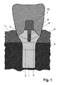
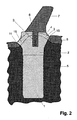
図1には、チタンから成る一体的な歯根インプラントとその上に固定されたクラウン10が、口蓋の方向に見た横断面として図示されている。分かり易くするために、図2は、補綴用取付ピン7を備えたインプラントの横断面を顎の骨の方向に見た形で図示している。
FIG. 1 shows an integral root implant made of titanium and a
インプラントは、下方の骨内領域1と、上方の骨内領域2と、歯肉移行領域3と、歯肉に移行するインプラント頭部4とから構成されている。このインプラントを作るために、未加工品から、領域1と領域2は、CAD/CAMを用いて作られ、領域3と歯肉に移行するインプラント頭部4は、CAD/CAMを用いて、或いは手動による処理によって作られる。
The implant is composed of a lower
顎の骨内に深く据え付けられる下方の骨内領域1は、ハニカムパターンを有し、ハニカムの角には、それぞれ尖端が有る。そのような実証済みの構造によって、インプラントの最適な根付きが可能となる。
The
下方の骨内領域1には、上方の骨内領域2が繋がっており、その上縁がちょうど顎の骨5の顎堤の上端にまで達するように作られている。それを実現するために、通常上方の骨内領域2は、その前庭側がそれ以外の箇所よりも著しく短く実現され、その口蓋側がそれ以外の箇所よりも若干短く実現されている。しかし、顎堤に正確に合わせるために、口蓋側を前庭側よりも短く実現しなければならない場合も有る。インプラント基底部の開削によって生じる骨の離開は、そのような特殊な造形によって解剖学的に完全に考慮されている。更に、広い設置面と骨5への力の良好な伝達を実現するために、上方の骨内領域2は、上に向かって拡がっている(漏斗形状)。また、領域2は、その粗削りされた表面のために、顎の骨5と癒合することができる。
The lower
領域2に続いて、滑らかに研磨された歯肉移行領域3が有る。この領域は、周囲を巡る形で歯肉の縁の約1mm下にまで達するように作られており、その深さは、凡そ健康な歯でも歯肉が歯と共に成長せずに、単に緩く接するような深さに相当する。この場合、滑らかに研磨されたチタン製の面によって、歯肉6との良好で刺激の無い癒合が可能となっている。
Following
同時にプレパラート境界面11を構成する歯肉移行領域3の端部には、歯肉に移行するインプラント頭部4が続いている。インプラント頭部4は、平坦でほぼ均一な内側の部分領域12とそれを取り囲む急峻に形成された部分領域13とから構成されており、これらの領域12/13は、(ここでは図示されていない)移行部分の無い形で、ほぼ球形に組み上げることもできる。急峻な部分領域13は、平坦な部分領域12を歯肉移行領域3と繋いでいる。インプラントが顎の骨5の顎堤に適合しているために、この部分領域13は、前庭/口前庭方向に関しては大抵それ以外の箇所よりも著しく長く急峻であり、口蓋/舌方向に関してはそれ以外の箇所よりも若干長く急峻になっている。
At the same time, the end of the
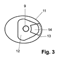
図3から分かる通り、インプラントの平坦な部分領域12には、補綴用取付ピンを固定するためのねじ孔が有る。更に、この部分領域12には、クラウンの捩じれを防止するための部分円の形の溝14が設けられており、そのために、クラウン10の下側には、それに対応する部分が形成されている。図2から分かる通り、個別に製作された補綴用取付ピン7が使用される。そのピンは、同じく溝14に食い込み、そのため捩じれに対しても係止される。真っ直ぐな標準的な取付ピン7を使用する場合、そのピンは溝14には食い込まずに、そのピン形状の部分だけがねじ込まれる。別途行われるクラウン10内にピンをセメントで固着して、更に、クラウンを溝14とプレパラート境界面11までのインプラント頭部4自体の形状の上に捩じれない形でインプラントと固定した場合、ピンが、捩じれない形でクラウン10と結合されることとなる。
As can be seen from FIG. 3, the flat
インプラントと接続する役割を果たすクラウン10の下側は、正確にプレパラート境界面11までのインプラント頭部4の形状と合致している。この場合、下側の周縁部の構造に関してはプレパラート境界面11の既に存在する幾何学データを使用するとともに、下側の面の製作に関してはインプラント頭部4の逆転させた幾何学データを使用することができることが有利である。
The underside of the
そのようにして適合されたクラウン10の下側は、全面に渡って隙間無く、セメント又は接着剤により、歯肉に移行するインプラント頭部4と接合される。接着又はセメントで固着する際に場合によっては漏れ出た材料は、プレパラート境界面11に良好にアクセスできるために、容易に取り去ることができる。更に、補綴用取付ピン7の滑らかな部分をクラウン内にセメントで固着する。取付ピン7の他方のねじ形状の側をインプラント頭部4にねじ込む。この場合、クラウン10とインプラントの間の全面的な接着部分は、噛む時に生じる力の大部分を吸収する。補綴ポスト7によって実現されるインプラント頭部4の平坦な部分12との接続及び平坦な設置部分は、横のずれを防止するとともに、剪断力の吸収及び分散を支援する役割を果たす。
The underside of the
図4〜7は、本発明の骨内領域に関する実施形態、即ち、インプラント基底部の形状を作るとともに、最終的に人工歯根システムの骨内領域の幾何学的な形状を決める、顎堤内への穴の開削形態を図示している。 4-7 are embodiments of the intraosseous region of the present invention, i.e., creating the shape of the implant base and ultimately determining the geometrical shape of the intraosseous region of the prosthetic root system. The form of drilling a hole is illustrated.
図4〜6の上の部分には、インプラント基底部に必要な個々の穴17〜19の位置が図示され、下の部分には、それらの重なり合った部分から得られるインプラント基底部20の形状が図示されている。これらの穴は、円筒形であり、同じ直径を有する。
The upper part of FIGS. 4-6 shows the location of the individual holes 17-19 required for the implant base, and the lower part shows the shape of the
図4には、二つの穴17,18が図示され、図5には、直線に沿って、図6には、正三角形の形で間隔を開けて並べられるとともに互いに傾斜された三つの穴17〜19が図示されている。直線に沿って配置された穴17〜19とそれによって形成されるインプラント基底部20では、インプラントは比較的大きな回転負荷に耐える一方、正三角形の形に配置された穴17〜19から構成されるインプラント基底部では、縦揺れのトルクに対して抵抗力を有する。
FIG. 4 shows two
図7からは、一方で穴17〜19の尖端がインプラント基底部20の最下点に該当し、他方で穴17〜19がインプラント基底部の全長上で交差していることが分かる。それによって、各横断面が関連し合う、インプラント基底部20又は下方の骨内領域の円錐形状が実現されている。
FIG. 7 shows that the tips of the
1 下方の骨内領域
2 上方の骨内領域
3 歯肉移行領域
4 歯肉に移行するインプラント頭部
5 顎の骨
6 歯肉
7 補綴用取付ピン
8 ねじ山
9 ねじ孔
10 クラウン
11 プレパラート境界面/周縁部
12 平坦な部分領域
13 急峻な部分領域
14 溝
15 前庭/口前庭側の短縮部分
16 口蓋/舌側の短縮部分
17〜19 穴
20 インプラント基底部
DESCRIPTION OF
Claims (10)
このインプラントの下方と上方の骨内領域(1,2)が、複数の円錐形の先端を持つように少なくとも二つの円筒体の幾何学的物体が重なり合う部分に相当する回転対称でない幾何学的な形状を有し、それらの物体の対称軸が、互いに平行に延びるか、或いはこのインプラントの下方と上方の骨内領域(1,2)が、一つの円錐形の先端だけを持つように少なくとも二つの円筒体の幾何学的物体が重なり合う部分に相当する回転対称でない幾何学的な形状を有し、それらの物体の対称軸が、下方の骨内領域(1)の下方終端内で交差して、その物体の対称軸の下端が単一の円錐形の先端を構成するように、それらの物体の対称軸が、互いに傾斜しており、これらの円筒体の幾何学的物体が、少なくともこれらの物体の対称軸を含む形で重なり合い、
上方の骨内領域(2)は、前庭/口前庭の方向における短縮部分(15)と口蓋/舌の方向における短縮部分(16)とをそれぞれ有し、それらの短縮部分は、上方の骨内領域(2)の上方の端部から始まり、歯肉移行領域(3)の下方の端部で終止し、それによって、上方の骨内領域(2)が正確に規定されるとともに、インプラント基底部の開削によって生じる骨の離開部で終止しており、
歯肉移行領域(3)の推移が回転対称でなく、歯肉移行領域(3)の各縦断面及び各横断面の形状が、当該の断面の前又は後に有る縦断面又は横断面の形状と異なっており、歯肉移行領域(3)の上方は、高さ、幅、深さが異なる形で三次元的に形成された、歯肉に移行するインプラント頭部(4)によって画定されるとともに、インプラント頭部(4)と歯肉移行領域(3)の互いの接合面によって、周囲を巡る形の周縁部(11)が形成されており、それによって、歯肉移行領域(3)が正確に規定されるとともに、この周縁部(11)がインプラント基底部の開削によって生じる歯肉の窩洞の上端から下に向かって1mm以内で終止している、
ことを特徴とする人工歯根システム。 Prosthetic root system consisting of an implant and a superstructure attached thereon, the implant having a lower intraosseous region (1) having a structure and an upper intraosseous region having a rough surface extending upwards (2) In the artificial tooth root system which is composed of a gingival transition region (3) having a smooth wall surface and an implant head (4) which transitions to the gingiva, and all these regions are connected to each other without a gap. ,
Lower and upper bone region of the implant (1, 2), geometrical not rotationally symmetrical, corresponding to the geometrical object overlaps portions of at least two of the cylindrical body to have a tip of a plurality of conical At least two such that the symmetry axes of the objects extend parallel to each other or the lower and upper bone regions (1, 2) of the implant have only one conical tip. Two cylindrical geometric objects having geometric shapes which are not rotationally symmetric corresponding to the overlapping parts, and the symmetry axes of these objects intersect within the lower end of the lower intraosseous region (1) The symmetry axes of the objects are inclined with respect to each other such that the lower ends of the symmetry axes of the objects constitute a single conical tip, and the geometric objects of these cylinders are at least these Overlap with the symmetry axis of the object There,
The upper intraosseous region (2) has a shortened portion (15) in the vestibular / mouth vestibular direction and a shortened portion (16) in the palatal / lingual direction, respectively. Starting from the upper end of the region (2) and ending at the lower end of the gingival transition region (3), so that the upper intraosseous region (2) is precisely defined and the base of the implant It ends at the dehiscence part of the bone caused by excavation,
Not transitive rotation symmetrical gingival transition region (3), the shape of the longitudinal section and the cross section of the gingival transition region (3) is different from the shape of a longitudinal section or cross-section is in the front or rear of the cross-section The upper part of the gingival transition region (3) is defined by an implant head (4) that transitions to the gingiva, which is three-dimensionally formed in different heights, widths and depths, and the implant head (4) and the gingival transition region (3) are connected to each other to form a peripheral edge (11) that surrounds the periphery, whereby the gingival transition region (3) is accurately defined, This peripheral edge (11) terminates within 1 mm downward from the upper end of the gingival cavity resulting from the excision of the implant base,
An artificial dental root system characterized by that.
Applications Claiming Priority (7)
| Application Number | Priority Date | Filing Date | Title |
|---|---|---|---|
| DE102007018453A DE102007018453B3 (en) | 2007-04-17 | 2007-04-17 | Dental implant system |
| DE102007018453.2 | 2007-04-17 | ||
| DE200810017086 DE102008017086A1 (en) | 2007-04-17 | 2008-04-02 | Dental implant system, has transgingival region confined upwards by transgingival implant head, where circumferential edge that is formed by abutting head and transgingival region runs under gingival edge after implantation |
| DE102008017086.0 | 2008-04-02 | ||
| DE102008017085.2 | 2008-04-02 | ||
| DE200810017085 DE102008017085A1 (en) | 2008-04-02 | 2008-04-02 | Dental implant system, has transgingival region confined upwards by transgingival implant head, where circumferential edge that is formed by abutting head and transgingival region runs under gingival edge after implantation |
| PCT/DE2008/000627 WO2008125097A1 (en) | 2007-04-17 | 2008-04-15 | Dental implant system |
Publications (2)
| Publication Number | Publication Date |
|---|---|
| JP2010524524A JP2010524524A (en) | 2010-07-22 |
| JP5543914B2 true JP5543914B2 (en) | 2014-07-09 |
Family
ID=41280277
Family Applications (1)
| Application Number | Title | Priority Date | Filing Date |
|---|---|---|---|
| JP2010503350A Expired - Fee Related JP5543914B2 (en) | 2007-04-17 | 2008-04-15 | Artificial tooth root system |
Country Status (12)
| Country | Link |
|---|---|
| US (1) | US20100330530A1 (en) |
| EP (1) | EP2142136B1 (en) |
| JP (1) | JP5543914B2 (en) |
| CN (1) | CN101808591B (en) |
| AU (1) | AU2008238423B2 (en) |
| BR (1) | BRPI0809733B8 (en) |
| CA (1) | CA2683978C (en) |
| DK (1) | DK2142136T3 (en) |
| ES (1) | ES2623455T3 (en) |
| PL (1) | PL2142136T3 (en) |
| RU (1) | RU2472466C2 (en) |
| WO (1) | WO2008125097A1 (en) |
Families Citing this family (11)
| Publication number | Priority date | Publication date | Assignee | Title |
|---|---|---|---|---|
| DE102008054186A1 (en) * | 2008-10-31 | 2010-05-12 | Böhm-van Diggelen, Bernd, Dr.med.dent. | Dental implant and method for introducing a recess in a jawbone, for insertion of an implant and for attaching a denture |
| DE102009003650A1 (en) * | 2009-03-20 | 2010-09-30 | Degudent Gmbh | Method of making an abutment |
| JP5680838B2 (en) * | 2009-06-08 | 2015-03-04 | 廣田 誠 | Artificial tooth root |
| IL201902A (en) | 2009-11-03 | 2012-12-31 | Ben-Zion Karmon | Dental implant |
| KR101134342B1 (en) * | 2010-04-22 | 2012-04-09 | 주식회사 메가젠임플란트 | Dental implant fixture and implant set having the same |
| US8712733B2 (en) * | 2010-09-17 | 2014-04-29 | Biocad Medical, Inc. | Adjusting dental prostheses based on soft tissue |
| CN202568500U (en) * | 2010-12-10 | 2012-12-05 | 西安中邦种植体技术有限公司 | Implant with flange on head part |
| US9168110B2 (en) | 2012-05-29 | 2015-10-27 | Biomet 3I, Llc | Dental implant system having enhanced soft-tissue growth features |
| KR101388846B1 (en) * | 2013-09-10 | 2014-04-23 | 왕제원 | One body implant |
| USD765856S1 (en) | 2014-02-14 | 2016-09-06 | Vita Zahnfabrik H. Rauter Gmbh & Co. Kg | Dental implant |
| USD810294S1 (en) * | 2015-12-15 | 2018-02-13 | Betzalel Messinger | Bone implant |
Family Cites Families (27)
| Publication number | Priority date | Publication date | Assignee | Title |
|---|---|---|---|---|
| FR1592462A (en) * | 1968-11-21 | 1970-05-11 | ||
| BR7202932D0 (en) * | 1972-02-24 | 1973-12-06 | H Brainin | DENTAL IMPLANT |
| DE2630400C2 (en) * | 1976-07-06 | 1981-10-08 | Hans Dr.med. Dr.med.dent. 8000 München Scheicher | Bone drill |
| CH625412A5 (en) * | 1976-07-06 | 1981-09-30 | Scheicher Hans | |
| JPS63119749A (en) * | 1985-11-27 | 1988-05-24 | 川原 春幸 | Dental implant having multiple capillary structure |
| JPS63281643A (en) * | 1987-05-14 | 1988-11-18 | Nikon Corp | Core for dental implant |
| JPH07102217B2 (en) * | 1991-05-23 | 1995-11-08 | 克成 西原 | An artificial tooth root with the function of a natural tooth root |
| TW442271B (en) * | 1994-07-19 | 2001-06-23 | Reimplant Dentale Sytsteme Gmb | Process for preparing a dental implant |
| US5759036A (en) * | 1996-07-29 | 1998-06-02 | Hinds; Kenneth F. | Complete dental implant system and method |
| US5984681A (en) * | 1997-09-02 | 1999-11-16 | Huang; Barney K. | Dental implant and method of implanting |
| US6174167B1 (en) * | 1998-12-01 | 2001-01-16 | Woehrle Peter S. | Bioroot endosseous implant |
| EP1013236B1 (en) * | 1998-12-11 | 2000-11-08 | Dinkelacker, Wolfgang, Dr. med. dent. | Dental implant and manufacturing method |
| RU2146113C1 (en) * | 1999-03-10 | 2000-03-10 | Перова Марина Дмитриевна | Osteointegrated dental implant |
| NL1013536C2 (en) * | 1999-11-09 | 2001-05-11 | Johannes Cornelis Stanislas Be | Dental implant. |
| US6854972B1 (en) * | 2000-01-11 | 2005-02-15 | Nicholas Elian | Dental implants and dental implant/prosthetic tooth systems |
| US7303396B2 (en) * | 2001-08-10 | 2007-12-04 | Juan Carlos Abarno | Split implant for dental reconstruction |
| SE523024C2 (en) * | 2002-07-25 | 2004-03-23 | Nobel Biocare Ab | Device for inducing bone by bone inductive or bioactive agent and / or increasing the stability of jaw bone implants and implants therefor |
| US7179088B2 (en) * | 2003-03-18 | 2007-02-20 | Cagenix, Inc. | Lobed dental implant |
| US9364330B2 (en) * | 2003-06-25 | 2016-06-14 | Biedermann Technologies Gmbh & Co. Kg | Tissue integration design for seamless implant fixation |
| DE20319904U1 (en) * | 2003-12-19 | 2004-04-01 | Trumpf Grüsch AG | Slitting shears for cutting processing of plate-like workpieces, in particular sheets |
| ITMI20032618A1 (en) * | 2003-12-30 | 2005-06-30 | Ioannis Corcolis | DENTAL IMPLANT |
| NZ549250A (en) * | 2004-02-20 | 2009-12-24 | Woodwelding Ag | An implant for bone tissue using a stepped profile and a liquefiable material to connect the implant to the bone |
| DE602004010613T3 (en) * | 2004-03-25 | 2013-12-24 | Straumann Holding Ag | Improved endosseous dental implant |
| DE102004055831A1 (en) * | 2004-11-19 | 2006-06-01 | Richter, Ole, Dr. med. dent. | Tooth implant, comprising upper end covered with ceramic layer for more natural appearance |
| WO2006084346A1 (en) * | 2005-02-11 | 2006-08-17 | Medin Tech | Implant system and method of installation thereof, and kit comprising the same |
| US7618258B2 (en) * | 2005-11-18 | 2009-11-17 | Form And Function Dental Services, P.C. | Slanted dental implant |
| US7758344B2 (en) * | 2005-11-18 | 2010-07-20 | Form And Function Dental Services, P.C. | Asymmetrical dental implant and method of insertion |
-
2008
- 2008-04-15 ES ES08757938.9T patent/ES2623455T3/en active Active
- 2008-04-15 WO PCT/DE2008/000627 patent/WO2008125097A1/en active Application Filing
- 2008-04-15 BR BRPI0809733A patent/BRPI0809733B8/en not_active IP Right Cessation
- 2008-04-15 PL PL08757938T patent/PL2142136T3/en unknown
- 2008-04-15 RU RU2009142022/14A patent/RU2472466C2/en not_active IP Right Cessation
- 2008-04-15 US US12/596,372 patent/US20100330530A1/en not_active Abandoned
- 2008-04-15 EP EP08757938.9A patent/EP2142136B1/en not_active Not-in-force
- 2008-04-15 CN CN200880012722.1A patent/CN101808591B/en not_active Expired - Fee Related
- 2008-04-15 JP JP2010503350A patent/JP5543914B2/en not_active Expired - Fee Related
- 2008-04-15 DK DK08757938.9T patent/DK2142136T3/en active
- 2008-04-15 AU AU2008238423A patent/AU2008238423B2/en not_active Ceased
- 2008-04-15 CA CA2683978A patent/CA2683978C/en not_active Expired - Fee Related
Also Published As
| Publication number | Publication date |
|---|---|
| CA2683978C (en) | 2015-06-30 |
| PL2142136T3 (en) | 2017-10-31 |
| RU2472466C2 (en) | 2013-01-20 |
| AU2008238423A1 (en) | 2008-10-23 |
| BRPI0809733B8 (en) | 2021-06-22 |
| EP2142136A1 (en) | 2010-01-13 |
| ES2623455T3 (en) | 2017-07-11 |
| DK2142136T3 (en) | 2017-05-08 |
| CN101808591B (en) | 2014-05-28 |
| EP2142136B1 (en) | 2017-01-25 |
| AU2008238423B2 (en) | 2013-10-10 |
| US20100330530A1 (en) | 2010-12-30 |
| CA2683978A1 (en) | 2008-10-23 |
| WO2008125097A1 (en) | 2008-10-23 |
| WO2008125097A4 (en) | 2009-01-29 |
| RU2009142022A (en) | 2011-05-27 |
| JP2010524524A (en) | 2010-07-22 |
| CN101808591A (en) | 2010-08-18 |
| BRPI0809733A2 (en) | 2014-10-14 |
| BRPI0809733B1 (en) | 2018-11-27 |
Similar Documents
| Publication | Publication Date | Title |
|---|---|---|
| JP5543914B2 (en) | Artificial tooth root system | |
| US5873721A (en) | Implant abutment systems, devices, and techniques | |
| US5527182A (en) | Implant abutment systems, devices, and techniques | |
| US8827704B2 (en) | System, method and apparatus for implementing dental implants | |
| JP6055488B2 (en) | Soft tissue preservation type dental implant component | |
| US20150044635A1 (en) | Abutment capable of accommodating core crowns manufactured at various angles and functioning as a healing abutment having a cap attached thereto, method for manufacturing dental implant prostheses using the abutment, and method for implant surgery using the abutment | |
| KR100407796B1 (en) | Prosthetic dentistry for false teeth that is made from pin retented inlay bridge | |
| AU2002236309A1 (en) | Pin-retained inlay bridge and process of making and fitting such | |
| TWI578965B (en) | Dental implants | |
| US9039416B2 (en) | Splint abutment over osseointegrated implant and compensatory slanted coping | |
| CA2630592C (en) | Splint abutment over osseointegrated implant and compensatory slanted coping | |
| US20210186664A1 (en) | Bone-bonded artificial tooth structure | |
| KR200392276Y1 (en) | Dental Implant | |
| KR200392241Y1 (en) | Dental Temporary Implant | |
| US9259298B2 (en) | Dental implant system | |
| KR200242258Y1 (en) | Pin retented inlay bridge | |
| TW202123896A (en) | Dental implant simulation | |
| JP2004344321A (en) | Denture fixing frame for dental implant |
Legal Events
| Date | Code | Title | Description |
|---|---|---|---|
| RD04 | Notification of resignation of power of attorney |
Free format text: JAPANESE INTERMEDIATE CODE: A7424 Effective date: 20100604 |
|
| A621 | Written request for application examination |
Free format text: JAPANESE INTERMEDIATE CODE: A621 Effective date: 20110414 |
|
| A521 | Request for written amendment filed |
Free format text: JAPANESE INTERMEDIATE CODE: A523 Effective date: 20120413 |
|
| A977 | Report on retrieval |
Free format text: JAPANESE INTERMEDIATE CODE: A971007 Effective date: 20121122 |
|
| A131 | Notification of reasons for refusal |
Free format text: JAPANESE INTERMEDIATE CODE: A131 Effective date: 20121225 |
|
| A521 | Request for written amendment filed |
Free format text: JAPANESE INTERMEDIATE CODE: A523 Effective date: 20130322 |
|
| A131 | Notification of reasons for refusal |
Free format text: JAPANESE INTERMEDIATE CODE: A131 Effective date: 20131008 |
|
| A521 | Request for written amendment filed |
Free format text: JAPANESE INTERMEDIATE CODE: A523 Effective date: 20131220 |
|
| TRDD | Decision of grant or rejection written | ||
| A01 | Written decision to grant a patent or to grant a registration (utility model) |
Free format text: JAPANESE INTERMEDIATE CODE: A01 Effective date: 20140422 |
|
| A61 | First payment of annual fees (during grant procedure) |
Free format text: JAPANESE INTERMEDIATE CODE: A61 Effective date: 20140509 |
|
| R150 | Certificate of patent or registration of utility model |
Ref document number: 5543914 Country of ref document: JP Free format text: JAPANESE INTERMEDIATE CODE: R150 |
|
| R250 | Receipt of annual fees |
Free format text: JAPANESE INTERMEDIATE CODE: R250 |
|
| R250 | Receipt of annual fees |
Free format text: JAPANESE INTERMEDIATE CODE: R250 |
|
| R250 | Receipt of annual fees |
Free format text: JAPANESE INTERMEDIATE CODE: R250 |
|
| LAPS | Cancellation because of no payment of annual fees |