JP5543337B2 - Hybrid cable for sending data and power - Google Patents
Hybrid cable for sending data and power Download PDFInfo
- Publication number
- JP5543337B2 JP5543337B2 JP2010510909A JP2010510909A JP5543337B2 JP 5543337 B2 JP5543337 B2 JP 5543337B2 JP 2010510909 A JP2010510909 A JP 2010510909A JP 2010510909 A JP2010510909 A JP 2010510909A JP 5543337 B2 JP5543337 B2 JP 5543337B2
- Authority
- JP
- Japan
- Prior art keywords
- signal
- hybrid cable
- connector
- braided metal
- conductor
- Prior art date
- Legal status (The legal status is an assumption and is not a legal conclusion. Google has not performed a legal analysis and makes no representation as to the accuracy of the status listed.)
- Expired - Fee Related
Links
Images


Description
本発明は、電気装置又は電子装置間において、デジタル信号を運ぶ第1の導電体セットと、交流作動電力又は直流作動電力を運ぶ第2の導電体セットとを有するハイブリッドケーブルに関する。本発明は、特に、輸送手段(vehicle)又は他の人工構造物の電気システムを構成し且つ離して配置された装置間において、デジタル信号及び作動電力を運ぶのに使用するハイブリッドケーブルに関する。 The present invention relates to a hybrid cable having a first conductor set for carrying digital signals and a second conductor set for carrying AC or DC operating power between electrical or electronic devices. The present invention particularly relates to a hybrid cable used to carry digital signals and operating power between remotely located devices that constitute the electrical system of a vehicle or other man-made structure.
[関連出願の相互参照]
本願は、2007年6月6日に出願し、「仮想電気及び電子装置インターフェース並びに管理システム(VIRTUAL ELECTRICAL AND ELECTRONIC DEVICE INTERFACE AND MANAGEMENT SYSTEM)」と題した米国特許出願第60/933,358号と、2008年6月6日に出願し、「データ及び電力を送るハイブリッドケーブル(HYBRID CABLE FOR CONVEYING DATA AND POWER)」と題した米国特許出願第12/134,454号との優先権を主張するものであり、これらの特許出願は、参照により本明細書に援用される。
[Cross-reference of related applications]
This application is filed on June 6, 2007 and is entitled US Patent Application No. 60 / 933,358 entitled “VIRTUAL ELECTRICAL AND ELECTRONIC DEVICE INTERFACE AND MANAGEMENT SYSTEM”; Filed on June 6, 2008 and claims priority to US Patent Application No. 12 / 134,454 entitled “HYBRID CABLE FOR CONVEYING DATA AND POWER”. These patent applications are hereby incorporated by reference.
輸送手段又は他の人工構造物の電気システム全体にわたって、デジタル通信及び電力供給の両方を処理する統合ネットワークを形成することは、多くの開発者の目標である。ネットワーク化した電気システムを構成する種々の電気/電子装置を接続する物理的接続要素の特性は、非常に重要である。物理的接続要素によって、データ通信及び電力供給の両面で、ネットワーク化された電気システムの構築、保守、及び変更の簡易化が促進されるようになることが好ましい。 It is the goal of many developers to form an integrated network that handles both digital communications and power supply throughout the electrical system of a vehicle or other man-made structure. The properties of the physical connection elements that connect the various electrical / electronic devices that make up the networked electrical system are very important. Preferably, the physical connection element facilitates the construction, maintenance, and simplification of networked electrical systems in both data communication and power supply.
従来の輸送手段の電気システム、例えば、量産自動車に使用される電気システムは、通常、専用の有線回路を備えたワイヤハーネスを使用して電力を分配し、専用の有線回路は、それぞれ離れた電気/電子装置から、その装置とつながっている電源及び/又は制御スイッチに延びている。さらに、大抵の従来の輸送手段配線システムは、物理的に分離した電力導体と(必要な場合に)信号導体とを利用する。そのような従来の配線システムは、通常は特定のモデル用であり、ネットワーク化の可能性が(あるとしても)限定されており、全体的な制御機能及びデータ収集機能を何ら提供しない。それ故、そのような配線システムは、ネットワーク通信及び電力供給を統合したものを容易に適用することができない。さらに、生産が開始されてしまうと、固定されたワイヤハーネスを利用する配線システムを変更することは非常に難しく、費用がかかる可能性がある。 Conventional transportation electrical systems, such as those used in mass-produced vehicles, typically use a wire harness with a dedicated wired circuit to distribute power, with each dedicated wired circuit being a separate electrical / Extends from the electronic device to a power supply and / or control switch connected to the device. In addition, most conventional vehicle wiring systems utilize physically separate power conductors (if necessary) and signal conductors. Such conventional wiring systems are usually for specific models, have limited (if any) networking possibilities and do not provide any overall control and data collection functions. Therefore, such a wiring system cannot be easily applied with an integrated network communication and power supply. Furthermore, once production begins, it is very difficult and expensive to change a wiring system that uses a fixed wire harness.
従来の輸送手段の電気システムにおける別の欠点は、(特に、自動車分野によく見られるが、)複数の電気回路に対する共通の中性点接続(すなわち接地接続)として、輸送手段のシャーシやフレームを使用することが広く普及して実施されていることである。このことが実施されたのは、自動車開発の初期の頃までさかのぼり、おそらく、コスト抑制の理由から継続されてきた。しかし、接地接続又は中性点接続として輸送手段のフレームやシャーシを使用することで、問題が生じることがある。まず、輸送手段のフレームやシャーシへの接地接続部は、輸送手段の耐用期間中で緩みを生じやすい。そのように接地接続部が緩むことにより、劣化した接続部の前後で電圧が降下し、このため、システムの電力供給面で支障をきたす。さらに、接地接続部が緩むと、電磁ノイズが発生することもあり、この電磁ノイズは、輸送手段のラジオや音響システムなどの輸送手段における他のサブシステムによって、「雑音」として取り込まれるかもしれない。データネットワークが輸送手段にある場合、そのような電磁ノイズは、ネットワーク通信の動作に干渉することもある。 Another drawback of conventional vehicle electrical systems is that the chassis or frame of the vehicle can be used as a common neutral connection (ie ground connection) for multiple electrical circuits (particularly common in the automotive field). It is widely used and implemented. This has been done since the early days of vehicle development, probably for reasons of cost control. However, the use of a vehicle frame or chassis as a ground connection or neutral point connection can cause problems. First, the ground connection of the transportation means to the frame or chassis tends to loosen during the life of the transportation means. As the ground connection is loosened, the voltage drops before and after the deteriorated connection, which hinders the power supply of the system. In addition, loose ground connections can cause electromagnetic noise that may be captured as "noise" by other subsystems in the vehicle, such as the vehicle's radio or acoustic system. . If the data network is in a vehicle, such electromagnetic noise can interfere with network communication operations.
現在のところ、マイクロコントローラ及び他の電気/電子コンポーネントが、輸送手段内で相互接続される場合は、相互接続は通常、装置に特化した(例えば、インストルメントパネル全体にわたる)ローカルバスを介して行われるか、又は、コントローラエリアネットワーク(CAN)プロトコルを使用するような専用の低速バスを通じて行われるかのいずれかによる。そのような相互接続は、設計に費用がかかり、通常、専用のアーキテクチャ及びソフトウェアに依存する。さらに、これらの相互接続は、少なくとも一部で、データ転送速度が制限されているために、一般的には、総合診断、障害検出、及び保守に関連したデータ収集に対応することができない。 Currently, when microcontrollers and other electrical / electronic components are interconnected within a vehicle, the interconnection is usually via a local bus that is device specific (eg, across the instrument panel). Either through a dedicated low speed bus such as using the Controller Area Network (CAN) protocol. Such interconnections are expensive to design and typically depend on dedicated architecture and software. In addition, these interconnections generally cannot accommodate data collection related to comprehensive diagnosis, fault detection, and maintenance due to limited data transfer rates, at least in part.
現代の輸送手段で使用される多数の電気装置、センサ、及び制御部をネットワークに、より良好に組み入れるために、より高いデータ転送速度が必要とされている。データ転送速度が良好になると、個々の装置を順次互いに接続して(例えば、「デイジーチェーンで接続して」)、ホストコンピュータを用いて高いレベルで制御し、監視することも可能となる。また、電磁ノイズをなくすことは、所望のデータ転送速度を達成するために重要である。 Higher data rates are needed to better incorporate the large number of electrical devices, sensors, and controls used in modern transportation into the network. When the data transfer rate becomes good, the individual devices can be sequentially connected to each other (for example, “connected in a daisy chain”), and can be controlled and monitored at a high level using a host computer. Also, eliminating electromagnetic noise is important to achieve the desired data transfer rate.
コンピュータの高速ネットワーク化では、広く使用される10Base−T方式、100Base−T方式、及び1000Base−T(ギガビットイーサネット(登録商標))(Gigabit Ethernet(登録商標))方式を含む「撚り対線によるイーサネット(登録商標)(Ethernet(登録商標))」などの、標準ネットワーク物理的接続方式(standard networking physical connectivity methods)を使用したものが公知であるが、これらの物理的接続による解決手法では、輸送手段、例えば、量産自動車の電気システムを構成する電気/電子装置の大部分をネットワーク化するには不十分である。これは、これらの物理的接続が、通常では、電力供給面を満足させることができないからである。例えば、10Base−T、100Base−T、及び1000Base−Tの物理的接続用に通常使用されるカテゴリ5、5e、6ケーブルは、元来電力容量に限度があり、この電力容量は、輸送手段に見られる高電流装置、例えば、自動車の直流電気モータ、電磁クラッチ、ソレノイド、照明などを確実に扱うのには不十分である。パワーオーバイーサネット(登録商標)(POE)などの改良された電力供給方式でさえ、一般的に、輸送手段全体にわたる電気システムのネットワークに対して十分な電力を供給することができない。 For high-speed networking of computers, the widely used 10Base-T system, 100Base-T system, and 1000Base-T (Gigabit Ethernet (registered trademark)) (Gigabit Ethernet (registered trademark)) system are used. (Registered trademark) (Ethernet (registered trademark)) "and the like that use standard networking physical connectivity methods (standard networking physical connectivity methods) are known. For example, it is insufficient to network most of the electric / electronic devices constituting the electric system of a mass-produced automobile. This is because these physical connections usually cannot satisfy the power supply aspect. For example, Category 5, 5e, 6 cables that are typically used for 10Base-T, 100Base-T, and 1000Base-T physical connections inherently have limited power capacity, and this power capacity is It is insufficient to reliably handle the high current devices found, such as automotive DC electric motors, electromagnetic clutches, solenoids, lighting, and the like. Even improved power supply schemes such as Power over Ethernet (POE) generally do not provide sufficient power to the network of electrical systems across the vehicle.
したがって、ネットワーク化した電気システム内を物理的に接続し、ネットワーク化したシステムのデータ通信面と電力供給面とをともに満足させるハイブリッドケーブルが必要である。 Accordingly, there is a need for a hybrid cable that physically connects the networked electrical system and satisfies both the data communication and power supply aspects of the networked system.
本発明の一態様では、ハイブリッドケーブルは、少なくとも1つの撚り対の信号導体を有する信号伝導コアを備える。第1の編組金属電力導体及び第2の編組金属電力導体が、信号導体のまわりに周状に配置され、電力導体間には絶縁層が配置されている。外側絶縁カバーが、第1の編組金属電力伝導層及び第2の編組金属電力伝導層並びにコアを囲んで配置されている。ハイブリッドケーブルの端部に配置された第1のコネクタが、各信号導体に対して接続ピン又は接触子付きレセプタクルの一方を有し、且つ各編組金属電力導体に接続された電力接触子を有する。一変形形態では、ハイブリッドケーブルは、2つの撚り対の信号導体を有し、最大10メガビット/秒(毎秒最大10メガビット)又は最大100メガビット/秒(毎秒最大100メガビット)のデータを送ることができる。別の変形形態では、ハイブリッドケーブルは、最大1000メガビット/秒(毎秒最大1000メガビット)のデータを送ることができる、4つの撚り対の信号導体を有する。信号伝導コアは、第1の電力導体の内側に配置された、絶縁材又は強化部材の一方を有することができ、撚り対の信号導体はコア内に配置されている。ハイブリッドケーブルは、ハイブリッドケーブルの第2の端部に配置された第2のコネクタをさらに有することができ、第1の編組電力導体、第2の編組電力導体、及び撚り対の信号導体はそれぞれ、第1のコネクタから第2のコネクタに連続して延びている。 In one aspect of the invention, a hybrid cable includes a signal conducting core having at least one twisted pair of signal conductors. A first braided metal power conductor and a second braided metal power conductor are disposed circumferentially around the signal conductor, and an insulating layer is disposed between the power conductors. An outer insulating cover is disposed around the first braided metal power conductive layer and the second braided metal power conductive layer and the core. A first connector located at the end of the hybrid cable has one of a connection pin or a receptacle with a contact for each signal conductor and has a power contact connected to each braided metal power conductor. In one variation, the hybrid cable has two twisted pairs of signal conductors and can transmit up to 10 megabits / second (up to 10 megabits per second) or up to 100 megabits per second (up to 100 megabits per second). . In another variation, the hybrid cable has four twisted pairs of signal conductors capable of sending up to 1000 megabits / second (up to 1000 megabits per second) of data. The signal conducting core can have one of an insulator or a reinforcing member disposed inside the first power conductor, with the twisted pair of signal conductors disposed within the core. The hybrid cable can further include a second connector disposed at the second end of the hybrid cable, wherein the first braided power conductor, the second braided power conductor, and the signal conductors of the twisted pair are each It extends continuously from the first connector to the second connector.
別の変形形態では、ハイブリッドケーブルは、少なくとも1つの撚り対の信号導体を有し、その信号導体のまわりに金属シールドが配置されている。第1の金属電力導体及び第2の金属電力導体が、信号導体に対して実質的に平行に配置され、外側絶縁カバーが、信号導体、金属シールド、及び電力導体を囲んで配置されている。ハイブリッドケーブルの第1の端部に配置されたコネクタが、各信号導体に対して接続ピン又はレセプタクルの一方を有し、且つ各電力伝導層に接続された接触子を有する。一変形形態では、ハイブリッドケーブルは、2つの撚り対の信号導体を有し、その信号導体は、最大10メガビット/秒のデータを送ることができる。別の変形形態では、ハイブリッドケーブルは、4つの撚り対の信号導体を有し、その信号導体は、最大1000メガビット/秒のデータを送ることができる。ハイブリッドケーブルは、ハイブリッドケーブルの第2の端部に配置された第2のコネクタを有することができ、第1の金属電力導体、第2の金属電力導体、及び撚り対の信号導体はそれぞれ、第1のコネクタから第2のコネクタに連続して延びている。 In another variation, the hybrid cable has at least one twisted pair of signal conductors with a metal shield disposed around the signal conductors. A first metal power conductor and a second metal power conductor are disposed substantially parallel to the signal conductor, and an outer insulating cover is disposed surrounding the signal conductor, the metal shield, and the power conductor. A connector disposed at the first end of the hybrid cable has one of a connection pin or receptacle for each signal conductor and a contact connected to each power conducting layer. In one variation, the hybrid cable has two twisted pairs of signal conductors that can carry up to 10 megabits / second of data. In another variation, the hybrid cable has four twisted pairs of signal conductors, which can carry up to 1000 megabits / second of data. The hybrid cable can have a second connector disposed at a second end of the hybrid cable, wherein the first metal power conductor, the second metal power conductor, and the twisted pair of signal conductors are each It extends continuously from one connector to the second connector.
別の態様では、電気で作動するセンサと電力を動力とする装置とを有する電気システムを備える輸送手段は、データを送る信号導体と電力を伝導する電力導体とを有する少なくとも1つのハイブリッドケーブルを備え、信号導体は、最大10メガビット/秒のデータを送ることができる。外側カバーが、信号導体及び電力導体を覆って配置され、電力を動力とする複数の装置が、ハイブリッドケーブルを用いて順次接続されている。 In another aspect, a vehicle comprising an electrical system having an electrically activated sensor and a power powered device comprises at least one hybrid cable having a signal conductor for transmitting data and a power conductor for conducting power. The signal conductor can send up to 10 megabits / second of data. An outer cover is disposed over the signal conductor and the power conductor, and a plurality of devices powered by electric power are sequentially connected using a hybrid cable.
より完全に理解するために、添付の図面に関する説明をここで行う。 For a more complete understanding, reference will now be made to the accompanying drawings.
ここで図面を参照すると、本明細書では、同様の要素を示すのに、同様の参照番号が全体にわたって使用されている。データ及び電力を送るハイブリッドケーブルの様々な図及び実施形態が、図示及び説明され、他の可能な実施形態も説明されている。図は必ずしも一定の尺度で描かれているわけではなく、場合によっては、単に図示を目的として、図面は、所々で、誇張され且つ/又は簡略化されている。当業者ならば、可能な実施形態についての下記の実施例を基にして、多くの可能な応用例及び変形形態を理解するであろう。 Referring now to the drawings, like reference numerals have been used throughout to designate like elements. Various views and embodiments of hybrid cables for transmitting data and power are shown and described, as well as other possible embodiments. The figures are not necessarily drawn to scale, and in some cases the drawings are exaggerated and / or simplified in several places for illustrative purposes only. Those skilled in the art will appreciate many possible applications and variations based on the following examples of possible embodiments.
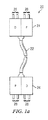
ここで図1aを参照すると、本開示によるハイブリッドケーブル20の概略図が示されており、ハイブリッドケーブル20は、輸送手段又は他の人工構造物におけるネットワーク化された電気システム全体にわたって、デジタル信号及び電力の両方を運ぶように構成されている。この適用例において、「輸送手段」という用語は、それらに限定するものではないが、自動車、トラック、単車、列車、軽量軌道車両、モノレール、航空機、ヘリコプタ、ボート、船舶、潜水艦、及び宇宙船を含めた任意の可動な人工構造物を指すことができる。「他の人工構造物」という用語は、それらに限定するものではないが、オフィスビル、商業ビル、倉庫、集合住宅ビル、及び一戸建て住宅を含む不動な人工構造物を指すことができる。
Referring now to FIG. 1a, a schematic diagram of a
ハイブリッドケーブル20は、デジタルデータを運ぶ第1の内部導体セット(例えば、図2aの導体114)と、電力(電流及び電圧)を運ぶ第2の内部導体セット(例えば、図2aの導体104、108)とを含むケーブル部分22を有する。コネクタ部材24が、ケーブル部分22の各端部に設けられている。各コネクタ部材24は、コネクタ部材24に取り付けられ且つ第1の内部導体セットのそれぞれに機能可能に接続された、複数の第1の電気端子26と、コネクタ部材24に取り付けられ且つ第2の内部導体セットのそれぞれに機能可能に接続された、複数の第2の電気端子28とを有する。当然のことながら、一方のコネクタ部材24の第1の電気端子26及び第2の電気端子28は、もう一方のコネクタ部材の各第1の電気端子及び各第2の電気端子と常に電気的に接続されているので、ケーブル20が一方の端部の端子26から他方の端部の端子26にデータ信号を運び、一方の端部の端子28から他方の端部の端子28に電力を運ぶのが可能になる。実施形態によっては、ハイブリッドケーブル20は、特定の浸入保護規格(ingress protection standard)(例えば、IP−67又は同等のレベルの保護シールとしての資格を得るもの)を満たす防水コネクタ(図示せず)を有することができ、この浸入保護規格により、接続されるネットワーク装置に頑丈なインターフェースがもたらされる。
The
ハイブリッドケーブル20の電力導体及び電力端子28によって運ばれる電力は、所望の電圧又は所望の電圧範囲で、直流電流又は交流電流のいずれかの形態をとることができる。例えば、ハイブリッドケーブルの実装形態の中には、直流12ボルトの電力の用途に対応しさえすればよいものもあり得るし、一方、他の実装形態では、より高い電圧、例えば、直流24ボルト、直流48ボルト、又は、50Hz/60Hzで交流110ボルト/交流220ボルトなどを必要とすることもある。実施形態によっては、ハイブリッドケーブルの電圧/電力の定格は、色分けされたケーブル部分22若しくはコネクタ部材24を使用する、並びに/又は、電力的に適合しない機器を接続する可能性をなくすために異なった形に形成し且つキーを設けた、コネクタ部材24及び/若しくは端子26、28を使用することによって、識別される。
The power carried by the power conductor and
さらに下記で説明するように、実施形態によっては、ハイブリッドケーブル20のデータ導体及びデータ端子26は、1つ又は複数の高速ネットワーク通信プロトコルに対応するように構成されている。例えば、ハイブリッドケーブル20は、様々なレベルのイーサネット(登録商標)(例えば、10baseT、100baseT、及び1000baseT)に対応することができる。他の実施形態では、イーサネット(登録商標)に加えて、又はこれの代替として、ユニバーサルシリアルバス(USB)プロトコル、ファイヤワイヤ、CAN、及びフッレクスレイ(Flexray)などのプロトコルに対応することができる。さらに別の実施形態では、コネクタ部材24は、過酷な適用環境に適した温度定格をもつ耐蝕性材料から、航空宇宙規格で製造されてもよい。さらにほかの実施形態では、ケーブル部分22は、整合する被覆物を有することができ、そして、ネットワークデータトラフィックに干渉しないレベルに、クロストーク(crosstalk)又は他のノイズを維持するのに十分なシールドで、被覆されてもよい。
As described further below, in some embodiments, the data conductors and
変形形態によっては、ハイブリッドケーブル20は、接地ループの防止、ノイズの低減、及び信頼性の向上のために、中性配線を単一ケーブルの概念の中に組み込んでいる。すでに説明したように、自動車、ボート、航空機、及び同様の環境のものは、従来から輸送手段の金属シャーシを直流動作電圧用のリターンパスとして使用してきた。このことは、主にコスト節減策として行われるが、下流に不具合をもたらす恐れがある。例えば、接地への複数の電気的接続部は、使用する材料の仕上げ及び組成に応じた異なるガルバニ電位状態となることがあり、このことは、すでに不良な動作環境にある場合、腐蝕を加速させる恐れがある。回路の電気抵抗は、時間の経過とともに変化することにより、同じ共通した接地に伝わる電圧を変化させることがあり、そして、回路経路間に電気ノイズをしばしば引き起こす。よって、本明細書に開示されるようなハイブリッドケーブル20を使用することにより、これらの問題が最小化されるか又はなくなる。そして、それは、ハイブリッドケーブル20が、気密性、高信頼性の接続部を有する保護された接地線として構成され、接続部が、電気回路のリターンパスを絶縁し、引き起こされる電気クロストークを最小限にするか又はなくすように設計されているためである。
In some variations, the
ここで図1bを参照すると、輸送手段のネットワーク化された電気システム内を物理的に接続するハイブリッドケーブル20の概略図が示されている。この実施形態では、電気システム30は、ネットワークコントローラ32、ハイブリッドな(hybrid)データ/電力スイッチ34、及び3つの装置モジュール36、38、40を有する。コントローラ32は、デジタルデータ信号44を用いてコンピュータ46や他の制御装置と双方向通信を行うための、複数のデータ端子42を有する。コントローラ32はまた、電源52から電力50を受け取るための複数の電力端子48を有する。コントローラはさらに、ケーブルインターフェース(cable interface)54を有し、ケーブルインターフェース54は、デジタルデータ信号44を送信/受信するための端子と、電力50を送るための他の端子とを含む。スイッチ34は、1つの入力ポート56及び3つの出力ポート58を有し、各ポートは、ケーブルインターフェース54を有し、ケーブルインターフェース54は、デジタルデータ信号44を送信/受信するための端子と、電力50を受け取る(入力ポートの場合)か、又は送る(出力ポートの場合)ための他の端子とを含む。各装置モジュール36、38、40は、電気/電子装置、このケースでは、ライト60、燃料センダ(gas gauge sender)62、及び回転計64にそれぞれ動作可能に接続され、それにより、ネットワークコントローラ32に装置60、62、64を監視して操作することを可能にさせる低レベルのインターフェースが提供される。
Referring now to FIG. 1b, there is shown a schematic diagram of a
引き続き図1bを参照すると、ハイブリッドケーブル20は、各ネットワーク構成要素32、34、36、38、40のケーブルインターフェース54間に接続されている。ケーブルインターフェース54の物理的構成は、ハイブリッドケーブル20の端部部材24と相互に嵌め合うことによって、ケーブル20の各端部において装置同士の適切なデータ端子間又は電力端子間に電気的な導通をもたらすように選択されている。これにより、ネットワークにおけるデジタルデータ通信面及び電力供給面の両方のための、ネットワーク全体にわたる物理的な接続が得られる。すなわち、データ通信信号44が、スイッチ34を経由してコントローラ32から装置モジュール36、38、40に(そしてその逆に)双方向に進むのを可能にし、それと同時に、電力が、スイッチを経由してコントローラから装置モジュールに分配され、最終的には、装置60、62、64が作動するようにこれらの装置に供給されるのを可能にする。
Still referring to FIG. 1 b, the
ここで図2aを参照すると、本開示による別のハイブリッドケーブルのケーブル部分の横断面図が示されている。図示のように、ケーブル100は、ポリエチレン、ポリ塩化ビニル、又はテフロン(登録商標)などの適切な樹脂で形成することのできる外側カバー102を有する。第1の電力導体104が、カバー102の内側に配置されている。一変形形態では、電力導体104は、ケーブル100の内部でカバー102の下に周を囲むように延びる編組金属被覆である。絶縁層106が、第1の編組導体104の下に配置されている。第2の電力導体108が、絶縁層106の下で軸方向に配置されている。一変形形態では、第2の電力導体108は、ケーブル100の内部で絶縁層106の下に周を囲むように延びる第2の編組金属被覆を構成する。コア130が、第2の電力導体108の内側に配置されている。一変形形態では、コア130は、カバー110を有し、カバー110は、適切な樹脂から形成してもよい。2つの電力導体を使用することにより、電力導体104、108の一方は中性点接続又は接地接続することができるので、電力を動力とする装置を輸送手段のフレーム又はボディに接地する必要がなくなる。
Referring now to FIG. 2a, a cross-sectional view of the cable portion of another hybrid cable according to the present disclosure is shown. As shown, the
撚り対の信号導体114が、コア130内に配置されている。図示した実施形態では、2つの撚り対の信号導体114が示されているが、他の変形形態では、単一の撚り対の信号導体が使用されてもよく、或いは3つ以上の撚り対の信号導体が使用されてもよい。この撚り対構成は、パルス状の直流電流が導体を流れて電磁誘導効果をもたらした場合に起こり得る、クロストークを低減するために使用される。2つの撚り対の信号導体は、10Base−T又は100Base−Tの物理的接続を使用して、10メガビット/秒(毎秒10メガビット)又は100メガビット/秒(毎秒100メガビット)のデータを送ることができる。4つの撚り対の信号導体を使用することにより、1000Base−Tの物理的接続を用いて最大1000メガビット/秒(毎秒最大1000メガビット)を送ることができる。一変形形態では、絶縁材112が、コア130内で撚り対の信号導体114を囲んで配置される。
A twisted pair of
本明細書で使用される「電力導体」という用語は、ファンモータ、フロントガラスのワイパモータ、輸送手段のヘッドライト、テールライト、方向指示器、及び同様の電力を動力とした装置などの装置に作動電流を送る導体を指す。それ故、輸送手段の電力導体は、例えば、1アンペア以上の電流を運ぶことができる。また、「信号導体」という用語は、装置アドレス、センサ測定値、及び制御信号などのデータを送るのに電気的な小信号を使用する導体を指す。信号導体を流れる電流は通常、ミリアンペアの範囲にある。したがって、電力導体を流れる電流は、信号導体を流れる電流よりも1000〜100,000倍程度大きくなり得る。 The term “power conductor” as used herein operates on devices such as fan motors, windscreen wiper motors, vehicle headlights, taillights, turn signals, and similar power-powered devices. A conductor that carries current. Thus, the power conductor of the vehicle can carry a current of, for example, 1 ampere or more. The term “signal conductor” also refers to a conductor that uses electrical small signals to send data such as device addresses, sensor measurements, and control signals. The current through the signal conductor is typically in the milliamp range. Therefore, the current flowing through the power conductor can be about 1000 to 100,000 times larger than the current flowing through the signal conductor.
図2bは、ケーブル100で使用するコネクタの端面図である。コネクタ116は、適切な非導電性材料で形成することのできるハウジング118を有する。図示のように、円形の金属ブレード又は突起120が、ハウジング118内に取り付けられている。ブレード120は、第1の電力導体104に接続され、その電力導体を流れる電流の流路を形成している。ブレード120は、第2のコネクタ又はレセプタクル(receptacle)内の嵌合する(mating)凹部又は相補的な凹部に挿入できるように構成されている。図示した実施形態では、ブレード120は、ハウジング118の内部で周を囲むように連続して延びている。他の変形形態では、ブレード120は、ハウジング118の内部で周を囲むように部分的に延びるか、又は、間隔をあけた複数の間隙を有するように配置された、複数の個別の接触子に分割することができる。
FIG. 2 b is an end view of the connector used with
環状をした凹部122が、ハウジング118内でブレード120の半径方向内側に形成されている。凹部122内に取り付けられた接触子124が、第2の電力導体108に接続されている。接触子124は、対になるコネクタに第2の電力導体108を接続する電気接触子を形成している。図示した実施形態では、単一の円形をした接触子124が、環状の凹部122によって形成される円周をまわるように延びている。他の変形形態では、凹部122の円周を部分的にだけまわるように延びる単一の接触子124を使用するか、又は、複数の接触子124を、凹部122の円周をまわるように、間隙をあけて離して配置することができる。接触子124は、第2の電力導体108に接続されている。
An
図3は、図2bの3−3線に沿って切り取った、コネクタ116の縦断面図である。一変形形態では、雌ねじが切られた金属カラー134は、ハウジング118を覆うように使用され、コネクタ116を対になるコネクタに連結し、コネクタをさらに保護することができる。図示のように、コネクタピン132及びピンレセプタクル126が、コネクタ116において、環状をした凹部122の半径方向内側に配置されている。接触子128が、ピンレセプタクル126の内側に配置されている。ピン132及び接触子128は、コネクタ116を通る信号経路を形成している。ピン132及び接触子128は、撚り対の導体114にそれぞれ接続することができる。一変形形態では、1つのピン132及び1つのレセプタクル126を、ケーブル100内の撚り対の信号導体114のそれぞれに対して設けることができる。
FIG. 3 is a longitudinal sectional view of the
理解されるように、ハイブリッドケーブルアセンブリ100は、電力及びデータを送る統合された手段を形成している。電力は、電力導体104、108を通じて送られ、一方、データ信号及び/又は制御信号は、撚り対の導体114を通じて送られる。電力導体104、108は、撚り対の信号導体114を電磁効果から遮蔽し、データ転送を改善する。
As will be appreciated, the
図4は、本開示によるハイブリッドケーブルの代替実施形態の横断面図である。図5は、図4のケーブル200で使用するコネクタの端面図である。図1〜3に示した実施形態と同様に、(図4に示した)ケーブル200は、カバー202、第1の電力導体204、絶縁層206、及び第2の電力導体208を有している。第1の電力導体204及び第2の電力導体208は、編組金属被覆とすることができる。コア230が、第2の導体208の半径方向内側に配置されている。コア230は、適切な非導電性材料で形成されたカバー210を有することができる。4つの撚り対の信号導体214がコア230内に配置されている。コア230はまた、撚り対の信号導体214を囲んで配置された絶縁材212を有することができる。一変形形態では、コア230は、強化部材236を有することにより、ケーブルアセンブリ200の強度を高め、撚り対の導体214の保護を強化することができる。強化部材236は、ワイヤ、樹脂フィラメント若しくは樹脂ストランド、及び/又は他の適切な繊維質で形成することができる。
FIG. 4 is a cross-sectional view of an alternative embodiment of a hybrid cable according to the present disclosure. FIG. 5 is an end view of the connector used in the
図5を参照すると、コネクタ216は、図2b及び図3に示したコネクタ116に構造上類似している。ハウジング218はハウジング118と同様であり、ブレード220はブレード120と同様であり、接触子224は接触子124と同様である。撚り対の信号導体214は、図1〜3に示した実施形態に関連してすでに説明したものと同様にして、ピン232とピンレセプタクル226内の接触子228とに接続されている。金属製若しくは樹脂製の、シールド又はカバー(図示せず)が、図3のカラー134と同様に、対になるコネクタ又はレセプタクルにコネクタ216を連結し且つ接続部を保護するために、設けられてよい。
Referring to FIG. 5, the
図6は、本開示による参考例のハイブリッドケーブルの斜視図である。図示のように、ハイブリッドケーブル300は、カバー302を有し、カバー302は、ポリ塩化ビニル、ポリエチレン、及び/又はテフロン(登録商標)などの適切な樹脂で形成できる。一変形形態では、雄コネクタ312は、ハイブリッドケーブル300の端部に取り付けられている。図示のように、コネクタ312は、ハウジング314と、第1の電力用突起316及び第2の電力用突起318とを有し、第1の電力用突起316及び第2の電力用突起318は、電力リード線又は電力導体304、306にそれぞれ接続されている。コネクタ312はまた、金属製のシールド320の内側に取り付けられた複数の信号伝送ピン322を有する。ピン322は、信号導体308に接続されており、信号導体308は、図1に示したものと同様の撚り対の導体とすることができる。一参考例では、信号導体308は、導体を電磁干渉から遮蔽するために、シールド320に接続された編組金属被覆310で覆われている。電力導体304、306は信号導体308とともに、カバー302で覆われている。ハイブリッドケーブル300は、単一の統合されたケーブルを通じて、電力及びデータの両方を送る。図示した参考例では、4つの撚り対の信号導体308が示されているが、使用する数量はそれより少なくても、又は多くてもよい。4つの撚り対の信号導体を使用することで、1,000Base−Tの物理的接続が可能になる。
FIG. 6 is a perspective view of a hybrid cable of a reference example according to the present disclosure. As shown, the
図7は、本開示によるハイブリッドケーブルを利用する車両400の概略図である。一変形形態では、ホストコンピュータ402が、電気機器を制御するために、且つ車両に配置された各種センサから入力信号を受け取り、この信号を処理するために設けられている。一変形形態では、図1a、図4、及び図6に関連して説明したものと同様に、ハイブリッドケーブル408が使用されて、ホストコンピュータ402を各種装置及びセンサに接続している。例えば、ケーブル408を使用して、ホストコンピュータ402をフロントガラスのワイパモータ404、エンジン制御モジュール406、及びヘッドライト410に接続することができる。ハイブリッドケーブル408を使用することで、これらの装置を「デイジーチェーン」で順次接続することが可能になり、それによって、各装置に対して別々に配線する必要がなくなる。各装置には、ネットワークアダプタを設けることができ、且つ/又は、装置から発信する信号若しくは装置に送られる信号を識別するために、媒体アクセス制御(MAC)やイーサネット(登録商標)ハードウェアアドレス(EHA)などの固有のアドレスを割り当てることができる。ハイブリッドケーブル408を利用してホストコンピュータ402に接続できる他の装置には、圧力センサ及び温度センサと、車両のシートに取り付けられた搭乗者存在センサ(passenger presence sensor)と、車両のタンク内の燃料の量及び車両のエンジンへの燃料の流れを監視するレベルセンサ及び流量計とがある。ハイブリッドケーブルを通じて送られるデータを使用することにより、車両の動作及び性能を反映する情報を監視及び収集し、それと同時に、電力を動力とする装置に作動電力を供給することができる。
FIG. 7 is a schematic diagram of a
このデータ及び電力を送るハイブリッドケーブルによって、自動車などの輸送手段において使用するように構成された、電力及びデータを送るハイブリッドケーブルが得られることは、本開示の恩恵を受ける当業者には理解されるであろう。当然のことながら、本明細書の図面及び詳細な説明は、限定的にではなく例示的に考えられるものであると理解すべきであり、開示した特定の形態及び実施例に限定していることを意図とするものではない。それどころか、当業者にとって明らかな、任意のさらなる修正、変更、再構成、置換、代替、設計選択、及び実施形態が、添付の請求項によって定義されるように、本発明の精神及び範囲から逸脱することなく、含まれている。それ故、添付の請求項が、かかるさらなる修正、変更、再構成、置換、代替、設計選択、及び実施形態をすべて包含すると解釈されることが意図されている。 Those skilled in the art having the benefit of this disclosure will appreciate that this hybrid cable for transmitting data and power provides a hybrid cable for transmitting power and data configured for use in a vehicle such as an automobile. Will. It should be understood that the drawings and detailed description herein are to be regarded as illustrative rather than restrictive, and are limited to the specific forms and examples disclosed. Is not intended. On the contrary, any further modifications, changes, rearrangements, substitutions, alternatives, design choices, and embodiments that will be apparent to those skilled in the art depart from the spirit and scope of the invention as defined by the appended claims. Without being included. Therefore, it is intended that the appended claims be construed to include all such further modifications, alterations, rearrangements, substitutions, alternatives, design choices, and embodiments.
Claims (17)
少なくとも1つの撚り対の信号導体を内部に有する信号伝導コアと、
前記信号伝導コアの外側周囲を囲むように周状に配置された第1の編組金属電力導体と、
前記第1の編組金属電力導体及び前記信号伝導コアの間で、前記信号伝導コアの外側周囲を囲むように周状に配置された第2の編組金属電力導体と、
前記第1の編組金属電力導体及び前記第2の編組金属電力導体の間で、前記第2の編組金属電力導体の外側周囲を囲むように周状に配置された内側絶縁層と、
前記第1の編組金属電力伝導層の外側周囲を囲むように周状に配置された外側絶縁カバーと、
該ハイブリッドケーブルの端部に配置された第1のコネクタであって、前記信号導体のそれぞれに対してコネクタピン又は接触子付きレセプタクルの一方を有し、且つ前記編組金属電力導体のそれぞれに接続された電気接触子を有する、第1のコネクタと
を備え、
前記信号伝導コアは、非導電性カバーと、前記非導電性カバーの内部で前記撚り対の信号導体を囲む絶縁材とをさらに有するハイブリッドケーブル。 A hybrid cable,
A signal conducting core having at least one twisted pair of signal conductors therein;
A first braided metal power conductor disposed circumferentially around the outer periphery of the signal conducting core;
A second braided metal power conductor disposed between the first braided metal power conductor and the signal conducting core so as to surround the outer periphery of the signal conducting core; and
An inner insulating layer disposed circumferentially between the first braided metal power conductor and the second braided metal power conductor so as to surround the outer periphery of the second braided metal power conductor;
An outer insulating cover arranged circumferentially so as to surround the outer periphery of the first braided metal power conductive layer;
A first connector disposed at an end of the hybrid cable having one of a connector pin or a receptacle with a contact for each of the signal conductors and connected to each of the braided metal power conductors; A first connector having electrical contacts ,
The signal conducting core further includes a non-conductive cover and an insulating material surrounding the twisted pair of signal conductors inside the non-conductive cover.
前記ハイブリッドケーブルの第2の端部に配置された第2のコネクタをさらに有し、前記第1の編組金属電力導体、前記第2の編組金属電力導体、及び前記撚り対の信号導体はそれぞれ、前記第1のコネクタから前記第2のコネクタに連続して延びる、ハイブリッドケーブル。 The hybrid cable according to any one of claims 1 to 6,
The hybrid cable further comprises a second connector disposed at a second end of the hybrid cable, wherein the first braided metal power conductor, the second braided metal power conductor, and the signal conductors of the twisted pair are each A hybrid cable extending continuously from the first connector to the second connector.
少なくとも1つの撚り対の信号導体を有する信号伝導コアであって、絶縁材をさらに有し、前記撚り対の信号導体が該信号伝導コア内に配置される信号伝導コアと、
前記信号伝導コアのまわりに周状に配置された第1の編組金属電力導体と、
前記第1の編組金属電力導体及び前記信号伝導コアの間で周状に配置された第2の編組金属電力導体と、
前記信号導体及び前記編組金属電力導体を囲んで配置された外側絶縁カバーと、
該ハイブリッドケーブルの端部に配置されたコネクタであって、前記信号導体のそれぞれに対してコネクタピン又はレセプタクルの一方を有し、且つ前記編組金属電力導体のそれぞれに接続された接触子を有するコネクタと、
前記コネクタのハウジングを覆い且つ前記コネクタを対になるコネクタに連結して前記コネクタを保護する金属カラーと
を備え、
前記信号伝導コアは、非導電性カバーをさらに有し、前記絶縁材は、前記非導電性カバーの内部で前記撚り対の信号導体を囲むハイブリッドケーブル。 In hybrid cable,
A signal conducting core having at least one twisted pair of signal conductors, further comprising an insulator, wherein the twisted pair of signal conductors is disposed within the signal conducting core;
A first braided metal power conductor disposed around the front SL signal conductor cores circumferentially,
A second braided metal power conductor disposed circumferentially between the first braided metal power conductor and the signal conducting core;
An outer insulating cover disposed surrounding the signal conductors及 beauty the braided metal power conductor,
A connector disposed at an end of the hybrid cable, the connector having one of a connector pin or a receptacle for each of the signal conductors, and a contact connected to each of the braided metal power conductors When,
A metal collar that covers the housing of the connector and protects the connector by connecting the connector to a mating connector ;
The signal conducting core further includes a non-conductive cover, and the insulating material surrounds the twisted pair of signal conductors inside the non-conductive cover.
前記ハイブリッドケーブルの第2の端部に配置された第2のコネクタをさらに有し、前記第1の編組金属電力導体、前記第2の編組金属電力導体、及び前記撚り対の信号導体はそれぞれ、前記第1のコネクタから前記第2のコネクタに連続して延びる、ハイブリッドケーブル。 The hybrid cable according to any one of claims 8 to 11,
The hybrid cable further comprises a second connector disposed at a second end of the hybrid cable, wherein the first braided metal power conductor, the second braided metal power conductor, and the signal conductors of the twisted pair are each A hybrid cable extending continuously from the first connector to the second connector.
本体と、
電気システムによって接続される、固有にアドレス指定可能な複数の下位システムと、
複数の電気で作動するセンサ、複数の電力を動力とする装置、並びに、データを送る信号導体及び電力を伝導する電力導体をもつ少なくとも1つのハイブリッドケーブルを有する前記電気システムであって、前記信号導体が、毎秒10メガビットのデータを送ることができ、前記複数の電気で作動するセンサ及び前記複数の電力を動力とする装置の少なくともいくつかが順次接続されている電気システムと
を備え、
前記ハイブリッドケーブルは、
少なくとも1つの撚り対の信号導体を内部に有する信号伝導コアと、
前記信号伝導コアの外側周囲を囲むように周状に配置された第1の編組金属電力導体と、
前記第1の編組金属電力導体及び前記信号伝導コアの間で、前記信号伝導コアの外側周囲を囲むように周状に配置された第2の編組金属電力導体と、
前記第1の編組金属電力導体及び前記第2の編組金属電力導体の間で、前記第2の編組金属電力導体の外側周囲を囲むように周状に配置された内側絶縁層と、
前記第1の編組金属電力伝導層の外側周囲を囲むように周状に配置された外側絶縁カバーと、
前記ハイブリッドケーブルの端部に配置された第1のコネクタであって、前記信号導体のそれぞれに対してコネクタピン又は接触子付きレセプタクルの一方を有し、且つ前記編組金属電力導体のそれぞれに接続された電気接触子を有する、第1のコネクタと
を備え、
前記複数の電力を動力とする装置及び前記複数の電気で作動するセンサの少なくともいくつかが、前記ハイブリッドケーブルを用いて順次接続され、
前記信号伝導コアは、非導電性カバーと、前記非導電性カバーの内部で前記撚り対の信号導体を囲む絶縁材とをさらに有する、輸送手段。 In the means of transport,
The body,
A plurality of uniquely addressable subsystems connected by an electrical system;
An electrical system comprising a plurality of electrically operated sensors, a plurality of power powered devices, and at least one hybrid cable having a signal conductor for transmitting data and a power conductor for conducting power, the signal conductor An electrical system capable of transmitting 10 megabits of data per second, wherein the plurality of electrically operated sensors and at least some of the plurality of power powered devices are sequentially connected,
The hybrid cable is
A signal conducting core having at least one twisted pair of signal conductors therein;
A first braided metal power conductor disposed circumferentially around the outer periphery of the signal conducting core;
A second braided metal power conductor disposed between the first braided metal power conductor and the signal conducting core so as to surround the outer periphery of the signal conducting core; and
An inner insulating layer disposed circumferentially between the first braided metal power conductor and the second braided metal power conductor so as to surround the outer periphery of the second braided metal power conductor;
An outer insulating cover arranged circumferentially so as to surround the outer periphery of the first braided metal power conductive layer;
A first connector disposed at an end of the hybrid cable having one of a connector pin or a receptacle with a contact for each of the signal conductors and connected to each of the braided metal power conductors; A first connector having electrical contacts ,
At least some of the plurality of power powered devices and the plurality of electrically operated sensors are sequentially connected using the hybrid cable;
The signal conducting core further includes a non-conductive cover and an insulating material surrounding the twisted pair of signal conductors inside the non-conductive cover.
前記ハイブリッドケーブルの第2の端部に配置された第2のコネクタをさらに有し、前記第1の編組金属電力導体、前記第2の編組金属電力導体、及び前記撚り対の信号導体がそれぞれ、前記第1のコネクタから前記第2のコネクタに連続して延びる、輸送手段。 15. The means of transportation according to claim 14,
And further comprising a second connector disposed at a second end of the hybrid cable, wherein the first braided metal power conductor, the second braided metal power conductor, and the signal conductors of the twisted pair are each Transportation means extending continuously from the first connector to the second connector.
Applications Claiming Priority (3)
| Application Number | Priority Date | Filing Date | Title |
|---|---|---|---|
| US12/134,454 US7740501B2 (en) | 2007-06-06 | 2008-06-06 | Hybrid cable for conveying data and power |
| US12/134,454 | 2008-06-06 | ||
| PCT/IB2008/002060 WO2008149236A2 (en) | 2007-06-06 | 2008-08-06 | Hybrid cable for conveying data and power |
Publications (3)
| Publication Number | Publication Date |
|---|---|
| JP2011522352A JP2011522352A (en) | 2011-07-28 |
| JP2011522352A5 JP2011522352A5 (en) | 2011-09-22 |
| JP5543337B2 true JP5543337B2 (en) | 2014-07-09 |
Family
ID=42027977
Family Applications (1)
| Application Number | Title | Priority Date | Filing Date |
|---|---|---|---|
| JP2010510909A Expired - Fee Related JP5543337B2 (en) | 2008-06-06 | 2008-08-06 | Hybrid cable for sending data and power |
Country Status (4)
| Country | Link |
|---|---|
| EP (1) | EP2176868A2 (en) |
| JP (1) | JP5543337B2 (en) |
| KR (1) | KR20110004349A (en) |
| CN (1) | CN101933102B (en) |
Families Citing this family (7)
| Publication number | Priority date | Publication date | Assignee | Title |
|---|---|---|---|---|
| DE102012014952B4 (en) * | 2012-07-30 | 2014-02-06 | Peter Baum | Device with a sauna cabin and method for operating a timer of a sauna control |
| WO2014206294A1 (en) * | 2013-06-28 | 2014-12-31 | 奇点新源国际技术开发(北京)有限公司 | Hybrid transmission cable |
| JP5822001B1 (en) * | 2014-07-11 | 2015-11-24 | 株式会社明電舎 | Flat cable for actuator |
| DE102017122492A1 (en) | 2017-09-27 | 2019-03-28 | Dürr Systems Ag | Applicator with an integrated control circuit |
| JP7263532B2 (en) * | 2019-02-28 | 2023-04-24 | アーベーベー・シュバイツ・アーゲー | Ethernet over basic interface between electric vehicle power supply equipment and electric vehicle |
| JP7398210B2 (en) * | 2019-06-14 | 2023-12-14 | 矢崎総業株式会社 | electrical junction box |
| US20220297319A1 (en) * | 2019-07-17 | 2022-09-22 | Abb Schweiz Ag | Robot arm link and robot |
Family Cites Families (9)
| Publication number | Priority date | Publication date | Assignee | Title |
|---|---|---|---|---|
| US2180731A (en) * | 1937-03-27 | 1939-11-21 | Anaconda Wire & Cable Co | Combined power and communication cable |
| JPS5418679U (en) * | 1978-07-14 | 1979-02-06 | ||
| JPS57116307A (en) * | 1981-01-13 | 1982-07-20 | Kingo Yoshida | Photoelectric coaxial cable |
| JP3011521B2 (en) * | 1991-03-28 | 2000-02-21 | 矢崎総業株式会社 | Electric wiring structure for vehicles |
| US5557698A (en) * | 1994-08-19 | 1996-09-17 | Belden Wire & Cable Company | Coaxial fiber optical cable |
| JP2001237034A (en) * | 2000-02-22 | 2001-08-31 | Sharp Corp | Cord for communications terminal and network system using it |
| US6780047B1 (en) * | 2000-03-24 | 2004-08-24 | Intel Corporation | Network communications system |
| US20030215197A1 (en) * | 2002-05-14 | 2003-11-20 | Simon Jonathan N. | Combined optical and electrical transmission line |
| FR2848719B1 (en) * | 2002-12-13 | 2005-03-04 | Nexans | MULTIFUNCTIONAL HYBRID CABLE FOR POWERING THE RESOURCES OF A USER STATION |
-
2008
- 2008-08-06 KR KR1020107000224A patent/KR20110004349A/en not_active Application Discontinuation
- 2008-08-06 CN CN2008801013552A patent/CN101933102B/en not_active Expired - Fee Related
- 2008-08-06 JP JP2010510909A patent/JP5543337B2/en not_active Expired - Fee Related
- 2008-08-06 EP EP08789014A patent/EP2176868A2/en not_active Withdrawn
Also Published As
| Publication number | Publication date |
|---|---|
| CN101933102A (en) | 2010-12-29 |
| EP2176868A2 (en) | 2010-04-21 |
| JP2011522352A (en) | 2011-07-28 |
| CN101933102B (en) | 2012-08-29 |
| KR20110004349A (en) | 2011-01-13 |
Similar Documents
| Publication | Publication Date | Title |
|---|---|---|
| US7740501B2 (en) | Hybrid cable for conveying data and power | |
| US8303337B2 (en) | Hybrid cable for conveying data and power | |
| JP5543337B2 (en) | Hybrid cable for sending data and power | |
| EP2377714B1 (en) | Train information transmitting and receiving system | |
| CN116142102A (en) | Vehicle circuit body | |
| CN105718409B (en) | Pin-configurable internal bus termination system | |
| MX2010011139A (en) | Usb isolation for vehicle communication interface. | |
| JP6597854B2 (en) | In-vehicle communication system | |
| WO2020122106A1 (en) | Joint connector | |
| CN104506400A (en) | Wiring method for improving reliability of controller area network (CAN) bus and CAN bus system | |
| CN111448623B (en) | Wiring system | |
| JP4744487B2 (en) | Train information transmission / reception system | |
| CN211789614U (en) | Feedback assembly of vehicle state information and vehicle-mounted ECU | |
| CN117751292A (en) | Device for checking the function of a cable shield of a wired communication connection | |
| CN110707481A (en) | Connector with power line carrier function | |
| TWI344428B (en) | ||
| JP2018157266A (en) | Wire harness system and ringing suppression method of wire harness system | |
| Chidlow et al. | Cost-effective multiplexing (automotive electronics) | |
| JP2011166550A (en) | Optical communication device, communication harness, and optical communication system |
Legal Events
| Date | Code | Title | Description |
|---|---|---|---|
| A521 | Request for written amendment filed |
Free format text: JAPANESE INTERMEDIATE CODE: A523 Effective date: 20110805 |
|
| A621 | Written request for application examination |
Free format text: JAPANESE INTERMEDIATE CODE: A621 Effective date: 20110805 |
|
| A711 | Notification of change in applicant |
Free format text: JAPANESE INTERMEDIATE CODE: A711 Effective date: 20111117 |
|
| A977 | Report on retrieval |
Free format text: JAPANESE INTERMEDIATE CODE: A971007 Effective date: 20130513 |
|
| A131 | Notification of reasons for refusal |
Free format text: JAPANESE INTERMEDIATE CODE: A131 Effective date: 20130521 |
|
| A601 | Written request for extension of time |
Free format text: JAPANESE INTERMEDIATE CODE: A601 Effective date: 20130821 |
|
| A602 | Written permission of extension of time |
Free format text: JAPANESE INTERMEDIATE CODE: A602 Effective date: 20130828 |
|
| A601 | Written request for extension of time |
Free format text: JAPANESE INTERMEDIATE CODE: A601 Effective date: 20130924 |
|
| A602 | Written permission of extension of time |
Free format text: JAPANESE INTERMEDIATE CODE: A602 Effective date: 20131001 |
|
| A521 | Request for written amendment filed |
Free format text: JAPANESE INTERMEDIATE CODE: A523 Effective date: 20131018 |
|
| A131 | Notification of reasons for refusal |
Free format text: JAPANESE INTERMEDIATE CODE: A131 Effective date: 20131112 |
|
| A601 | Written request for extension of time |
Free format text: JAPANESE INTERMEDIATE CODE: A601 Effective date: 20140212 |
|
| A602 | Written permission of extension of time |
Free format text: JAPANESE INTERMEDIATE CODE: A602 Effective date: 20140219 |
|
| A521 | Request for written amendment filed |
Free format text: JAPANESE INTERMEDIATE CODE: A523 Effective date: 20140312 |
|
| TRDD | Decision of grant or rejection written | ||
| A01 | Written decision to grant a patent or to grant a registration (utility model) |
Free format text: JAPANESE INTERMEDIATE CODE: A01 Effective date: 20140408 |
|
| A61 | First payment of annual fees (during grant procedure) |
Free format text: JAPANESE INTERMEDIATE CODE: A61 Effective date: 20140508 |
|
| R150 | Certificate of patent or registration of utility model |
Ref document number: 5543337 Country of ref document: JP Free format text: JAPANESE INTERMEDIATE CODE: R150 |
|
| LAPS | Cancellation because of no payment of annual fees |