JP5542578B2 - DC power supply system - Google Patents
DC power supply system Download PDFInfo
- Publication number
- JP5542578B2 JP5542578B2 JP2010187153A JP2010187153A JP5542578B2 JP 5542578 B2 JP5542578 B2 JP 5542578B2 JP 2010187153 A JP2010187153 A JP 2010187153A JP 2010187153 A JP2010187153 A JP 2010187153A JP 5542578 B2 JP5542578 B2 JP 5542578B2
- Authority
- JP
- Japan
- Prior art keywords
- storage battery
- current
- unit
- power
- power supply
- Prior art date
- Legal status (The legal status is an assumption and is not a legal conclusion. Google has not performed a legal analysis and makes no representation as to the accuracy of the status listed.)
- Expired - Fee Related
Links
Images


Classifications
-
- Y—GENERAL TAGGING OF NEW TECHNOLOGICAL DEVELOPMENTS; GENERAL TAGGING OF CROSS-SECTIONAL TECHNOLOGIES SPANNING OVER SEVERAL SECTIONS OF THE IPC; TECHNICAL SUBJECTS COVERED BY FORMER USPC CROSS-REFERENCE ART COLLECTIONS [XRACs] AND DIGESTS
- Y02—TECHNOLOGIES OR APPLICATIONS FOR MITIGATION OR ADAPTATION AGAINST CLIMATE CHANGE
- Y02E—REDUCTION OF GREENHOUSE GAS [GHG] EMISSIONS, RELATED TO ENERGY GENERATION, TRANSMISSION OR DISTRIBUTION
- Y02E10/00—Energy generation through renewable energy sources
- Y02E10/70—Wind energy
- Y02E10/76—Power conversion electric or electronic aspects
-
- Y—GENERAL TAGGING OF NEW TECHNOLOGICAL DEVELOPMENTS; GENERAL TAGGING OF CROSS-SECTIONAL TECHNOLOGIES SPANNING OVER SEVERAL SECTIONS OF THE IPC; TECHNICAL SUBJECTS COVERED BY FORMER USPC CROSS-REFERENCE ART COLLECTIONS [XRACs] AND DIGESTS
- Y02—TECHNOLOGIES OR APPLICATIONS FOR MITIGATION OR ADAPTATION AGAINST CLIMATE CHANGE
- Y02E—REDUCTION OF GREENHOUSE GAS [GHG] EMISSIONS, RELATED TO ENERGY GENERATION, TRANSMISSION OR DISTRIBUTION
- Y02E70/00—Other energy conversion or management systems reducing GHG emissions
- Y02E70/30—Systems combining energy storage with energy generation of non-fossil origin
Landscapes
- Charge And Discharge Circuits For Batteries Or The Like (AREA)
- Rectifiers (AREA)
- Inverter Devices (AREA)
- Supply And Distribution Of Alternating Current (AREA)
- Direct Current Feeding And Distribution (AREA)
Description
本発明は、直流給電システムに関し、特に直流給電部に蓄電池を直結した直流給電システムに関する。 The present invention relates to a DC power supply system, and more particularly to a DC power supply system in which a storage battery is directly connected to a DC power supply unit.
近年、太陽電池、風力発電装置及び燃料電池のような分散電源装置が普及し始めている。しかし、現状では分散電源装置で発電した直流電力が交流に変換され、電力を消費する機器において再度直流に変換されて使用される。このように、直流−交流変換及び交流−直流変換が行われるので、そのたびに、変換損失を生じる。そこで、分散電源が発電する直流電力を交流に変換することなく、直流電力のまま送電して機器で使用することにより、変換損失を低減させる直流給電システムが提案されている。
直流給電システムに関して、直流バスに接続された複数の電源ユニットがそれぞれ電流制御部を備え、各電流制御部が電源ユニットに入出力する電流に従い、自律的に直流電圧指令値または直流電圧の制御性を変更する機能を備えることにより、複数の分散電源が自律的に協調運転するとともに、装置容量に依存せずに、簡単にユニットを追加することを可能にする技術が公知である(例えば、特許文献1参照)。
In recent years, distributed power supply devices such as solar cells, wind power generators and fuel cells have begun to spread. However, at present, the DC power generated by the distributed power supply device is converted into AC, and is converted into DC again and used in a device that consumes power. In this way, since DC-AC conversion and AC-DC conversion are performed, a conversion loss occurs each time. In view of this, a DC power feeding system has been proposed in which DC power generated by a distributed power source is not converted to AC, but is transmitted as it is and used in equipment, thereby reducing conversion loss.
Regarding the DC power supply system, each of the multiple power supply units connected to the DC bus has a current control unit, and each current control unit autonomously controls the DC voltage command value or DC voltage according to the current input to and output from the power supply unit. A technology is known that allows a plurality of distributed power sources to autonomously cooperate in operation by adding a function to change the unit, and to easily add units without depending on the device capacity (for example, patents) Reference 1).
従来のこのようなシステムでは、複数の分散電源が自律的に協調運転することが可能になるが、1つの機器に急激な負荷変動が生じた場合に、直流バス電圧が変化し、そのため、他のユニットの入出力電流も変化する。このように、1つの機器に負荷変動が生じると、直流バス電圧が変化し、直流バス電圧の安定化は困難になる。また、負荷変動時には複数のユニットが同時に電圧制御状態となるため、直流バス電圧の安定化がさらに困難になる。それに加え、各ユニットの入出力電流変化に応じて直流バス電圧の制御目標値が変更されるため、システム全体の制御が複雑になり、直流バス電圧安定化が困難となる。
このように、各ユニットの電圧制御に代えて、直流バスに、例えば蓄電池のような電圧源を直結することにより、直流バス電圧を無制御で安定化することが可能である。蓄電池は電圧安定化能力が極めて高く、急峻な負荷変動が生じた場合においても直流バス電圧が常時安定化する。しかし、このように直流バスに蓄電池を直結するので、蓄電池と直流バスの間に電力変換器を備えることができず、そのため、蓄電池電流を制御することができない。
本発明は、上記課題に鑑みて、蓄電池を直流給電部に直結した場合でも実質的に蓄電池の電流または電力を所定値もしくは所定範囲内に制御可能にする直流給電システムを提供することを目的とする。
In such a conventional system, a plurality of distributed power sources can autonomously operate in a coordinated manner. However, when a sudden load fluctuation occurs in one device, the DC bus voltage changes. The input / output current of this unit also changes. As described above, when a load fluctuation occurs in one device, the DC bus voltage changes, and it becomes difficult to stabilize the DC bus voltage. Further, since the plurality of units are simultaneously in the voltage control state when the load changes, it becomes more difficult to stabilize the DC bus voltage. In addition, since the control target value of the DC bus voltage is changed according to the input / output current change of each unit, the control of the entire system becomes complicated and it becomes difficult to stabilize the DC bus voltage.
Thus, instead of voltage control of each unit, the DC bus voltage can be stabilized without control by directly connecting a voltage source such as a storage battery to the DC bus. The storage battery has an extremely high voltage stabilization capability, and the DC bus voltage is always stabilized even when a sudden load fluctuation occurs. However, since the storage battery is directly connected to the direct current bus in this way, a power converter cannot be provided between the storage battery and the direct current bus, and therefore the storage battery current cannot be controlled.
In view of the above problems, an object of the present invention is to provide a DC power supply system that can substantially control the current or power of a storage battery within a predetermined value or a predetermined range even when the storage battery is directly connected to a DC power supply unit. To do.
本発明の直流給電システムは、上記のような課題を解決するものであり、分散電源装置、負荷および系統電力システムが接続された直流給電部に蓄電池を直結し、前記蓄電池の入出力電流を検出する蓄電池電流検出部を備え、前記系統電力システムは、系統電力と直流給電部との間に交流を直流に、直流を交流に変換する電力変換器を有し、電力変換器は前記蓄電池電流検出部より得られる蓄電池電流情報に基づいて、前記電力変換器の出力を制御し、前記蓄電池電流または電力を所定値もしくは所定範囲内に制御することを特徴とする。 The DC power supply system of the present invention solves the above-described problems, and directly connects a storage battery to a DC power supply unit to which a distributed power supply device, a load, and a system power system are connected, and detects an input / output current of the storage battery. A storage battery current detection unit, wherein the grid power system includes a power converter that converts alternating current into direct current and direct current into alternating current between the grid power and the direct current power supply, and the power converter detects the storage battery current. The output of the power converter is controlled based on storage battery current information obtained from the unit, and the storage battery current or power is controlled within a predetermined value or a predetermined range.
本発明によれば、直流給電部に蓄電池を直結した直流給電システムにおいて、系統電力システムの電力変換器を蓄電池電流検出部より得られる蓄電池電流情報に基づいて制御することにより、蓄電池電流または電力を所定値もしくは所定範囲内にすることが可能となる。 According to the present invention, in a DC power supply system in which a storage battery is directly connected to the DC power supply unit, the storage battery current or power is controlled by controlling the power converter of the system power system based on the storage battery current information obtained from the storage battery current detection unit. It becomes possible to make it into a predetermined value or a predetermined range.
本発明の直流給電システムは、直流給電部に分散電源装置、負荷および系統電力と直流給電部との間に交流を直流に、直流を交流に変換する電力変換器を有する系統電力システムが接続されたシステムを指し、特に直流給電部に蓄電池を直結したものを発明の対象とする。本発明は、この直流給電システムにおいて、蓄電池の入出力電流を検出する蓄電池電流検出部を備え、前記系統電力システムは、前記蓄電池電流検出部より得られる蓄電池電流情報に基づいて、前記系統電力システムに備えられた電力変換器の出力を制御して、前記蓄電池電流を所定値もしくは所定範囲内に制御する。
これにより、直流給電部に蓄電池を直結した場合でも、系統電力システムの電力変換器を制御することにより、実質的に蓄電池の電流または電力を所望値もしくは所望範囲内に制御することが可能となる。
蓄電池を直結した直流給電システムにおいては、直流電圧値は蓄電池電圧とほぼ等価であるため、電流制御を行うことと電力制御(電圧×電流を制御)を行うことは同義である。よって、以降は電流制御という文言で統一することとする。
In the DC power supply system of the present invention, a system power system having a power converter that converts AC to DC and DC to AC is connected between the DC power supply unit between the distributed power supply device, the load and the system power and the DC power supply unit. In particular, a system in which a storage battery is directly connected to a DC power supply unit is an object of the invention. The DC power supply system according to the present invention includes a storage battery current detection unit that detects an input / output current of a storage battery, and the system power system is configured based on storage battery current information obtained from the storage battery current detection unit. And controlling the output of the power converter provided in the battery to control the storage battery current to a predetermined value or within a predetermined range.
Thereby, even when a storage battery is directly connected to the DC power supply unit, it is possible to substantially control the current or power of the storage battery within a desired value or a desired range by controlling the power converter of the system power system. .
In a DC power supply system in which a storage battery is directly connected, the DC voltage value is substantially equivalent to the storage battery voltage, and thus performing current control is synonymous with performing power control (controlling voltage × current). Therefore, the term “current control” will be unified thereafter.
本発明の直流給電システムにおいて、直流給電部は、分散電源装置、負荷および系統電力システムが接続された接続部分であり、直流給電部に蓄電池が直結される。従って、直流給電部に接続された分散電源装置、蓄電池または系統電力システムより、直流負荷に電力を供給する。
また、分散電源は、太陽光発電装置、風力発電装置または燃料電池のような発電装置を指す。
また、負荷は、家庭で使用されるようなエアコン、冷蔵庫、洗濯機、テレビ、照明装置またはパソコンのような電気機器であるが、オフィスで使用されるコンピュータ、複写機またはファクシミリのような電気機器であってもよい。また店舗で使用されるショーケース及び照明装置であってもよい。
また、系統電力システムは、電力会社より供給される商用交流電源であり、本発明では、分散電源で発電した電力を系統電力へ売電したり、系統電力から買電したりする。
また、蓄電池は、代表的には、リチウムイオン二次電池であるが、その他の電池、例えば鉛電池またはニッケル電池のような二次電池も使用可能である。負荷の消費電力に対応する電池容量をもつ蓄電池が選択される。
In the DC power supply system of the present invention, the DC power supply unit is a connection part to which the distributed power supply device, the load, and the system power system are connected, and the storage battery is directly connected to the DC power supply unit. Therefore, power is supplied to the DC load from the distributed power supply device, storage battery, or system power system connected to the DC power supply unit.
The distributed power supply refers to a power generation device such as a solar power generation device, a wind power generation device, or a fuel cell.
The load is an electric device such as an air conditioner, a refrigerator, a washing machine, a television set, a lighting device or a personal computer used at home, but an electric device such as a computer, a copying machine or a facsimile used in an office. It may be. Further, it may be a showcase and a lighting device used in a store.
The grid power system is a commercial AC power source supplied from an electric power company. In the present invention, the power generated by the distributed power source is sold to the grid power or purchased from the grid power.
The storage battery is typically a lithium ion secondary battery, but other batteries such as a secondary battery such as a lead battery or a nickel battery can also be used. A storage battery having a battery capacity corresponding to the power consumption of the load is selected.
また、電力変換器は、蓄電池電流検出部からの蓄電池電流情報に基づいて、電力変換器のスイッチング制御を行っている。
これにより、蓄電池充放電電流を所望値もしくは所望範囲内に制御可能とする。
Moreover, the power converter performs switching control of the power converter based on the storage battery current information from the storage battery current detection unit.
Thereby, the storage battery charge / discharge current can be controlled within a desired value or within a desired range.
また、本発明の直流給電システムは、実施形態において、更に、前記電力変換器の電流を検出する自経路検出部を備え、前記蓄電池電流検出部より得られる蓄電池電流情報または自経路検出部の自経路電流情報に基づいて、前記電力変換器のスイッチング制御を行っている。
これにより、系統電力システムの電力変換器は、自経路の電流制御を優先するか、蓄電池経路の電流制御を優先するかを選択することが可能となり、蓄電池が直結された直流給電システムにおいて制御可能な動作を増やすことができる。
In the embodiment, the DC power supply system of the present invention further includes a self-path detection unit that detects the current of the power converter, and the storage battery current information obtained from the storage battery current detection unit or the self-path detection unit. Based on the path current information, switching control of the power converter is performed.
As a result, the power converter of the grid power system can select whether to give priority to the current control of the own path or the current control of the storage battery path, and can be controlled in the DC power supply system directly connected to the storage battery. Can increase the number of operations.
また、本発明の直流給電システムは、実施形態において、少なくとも前記蓄電池残量情報(実施形態では直流給電部の直流電圧から推定)を用いて制御目標値を選択する制御目標値選択部を備え、前記制御目標値選択部より得られる切替信号によって、前記蓄電池電流情報または自経路検出情報を切り替える切替部を備える。
これにより、蓄電池残量、もしくは時間、もしくはその両方に対応した制御が可能になる。
Further, the DC power supply system of the present invention includes a control target value selection unit that selects a control target value using at least the storage battery remaining amount information (estimated from the DC voltage of the DC power supply unit in the embodiment) in the embodiment, A switching unit that switches the storage battery current information or the own path detection information according to a switching signal obtained from the control target value selection unit.
Thereby, control corresponding to the remaining amount of storage battery, time, or both becomes possible.
また、本発明の直流給電システムは、実施形態において、前記切替部は、前記制御目標値選択部より得られる切替信号によって、前記蓄電池電流情報または自経路検出情報を前記電力変換器のスイッチング素子を制御するスイッチング駆動信号生成部に供給するものである。 In the DC power supply system of the present invention, in the embodiment, the switching unit uses the switching signal obtained from the control target value selection unit to convert the storage battery current information or the own path detection information to the switching element of the power converter. It supplies to the switching drive signal generation part to control.
また、本発明の直流給電システムは、実施形態において、前記電力変換器は、DC/AC変換器およびAC/DC変換器、または双方向変換器である。
これにより、交流から直流、または直流から交流に変換することができる。
In the DC power supply system of the present invention, in the embodiment, the power converter is a DC / AC converter and an AC / DC converter, or a bidirectional converter.
Thereby, it is possible to convert from alternating current to direct current or from direct current to alternating current.
以下には、本発明の直流給電システムの実施形態を図面を使用して説明する。
<第1実施形態>
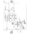
図1は、本発明の第1実施形態のブロック図を示す。図1に示すように、直流給電部1に、太陽光発電システム2と、蓄電池3と、系統電力システム4と、直流負荷5が接続される。このように、直流給電部は、太陽光発電システム2と、蓄電池3と、系統電力システム4が接続され、太陽光発電システム2、蓄電池3または系統電力システム4より、直流負荷5に電力を供給する部分である。図1は、直流給電部1、太陽光発電システム2、蓄電池3、系統電力システム4及び直流負荷5をそれぞれ1つ示すが、これらの個数は制限がなく、1つでも複数でもかまわない。
ここで、直流給電部1の電圧(蓄電池電圧)をV、太陽光発電システム2の出力電流をIpv、蓄電池3の放電電流をIdc、蓄電池3の充電電流をIch、系統電力システム4のDC/AC変換器42に流れる電流をIsell、AC/DC変換器43を流れる電流をIbuy、直流負荷5に供給される電流をIloadとし、以下説明する。
Hereinafter, an embodiment of a DC power feeding system of the present invention will be described with reference to the drawings.
<First Embodiment>
FIG. 1 shows a block diagram of a first embodiment of the present invention. As shown in FIG. 1, a solar
Here, the voltage (storage battery voltage) of the DC
太陽光発電システム2は、太陽電池21と、DC/DC変換器22とで構成される。この実施形態は、太陽光発電システムを分散電源装置の代表として説明するが、風力発電装置、燃料電池であってもよい。
太陽電池21は、結晶型太陽電池、多結晶型太陽電池または薄膜型太陽電池よりなり、ここでは、例えば、5kWを発電することができるものが使用される。
DC/DC変換器22は、太陽電池21の出力電圧を、直流給電部1の直流電圧に変換するものであり、直流給電部1の電圧と電流の両方を検出して、直流給電部側の電圧が蓄電池21の満充電(残量100%)の時の電圧(420V)以下においては、太陽電池21を最大電力点追従(MPPT)制御する。しかし、直流給電部側の電圧が蓄電池3の満充電(残量100%)の時の電圧(420V)に達した場合は、直流給電部側の電圧が蓄電池3の満充電(残量100%)の時の電圧(420V)に維持する制御に切り替える。この場合、太陽電池21を最大電力点追従(MPPT)制御することができないため、太陽電池の発電量をいくらか無駄にしてしまうことになる。
The solar
The
The DC /
蓄電池3は、例えば、リチウムイオン二次電池であり、定格電圧380V、10Ah(例えば、100直列、1並列)で構成され、直流給電部1に直結されている。ここで、直結とは、直流給電部1と蓄電池3の間に、DC/DC変換器のような電力変換器が介在されないという意味である。従って、直流給電部1と蓄電池3の電圧はほぼ等しくなる(実際には配線の電圧降下が存在する)。このリチウムイオン二次電池は、図2に示す容量―電圧曲線を持っている。即ち、このリチウムイオン二次電池は、電池容量が空の時は300V、20%の時は360V、50%の時は380V(定格電圧)、80%の時は400V、100%(満充電)の時は420Vである。ここでは、リチウムイオン二次電池を代表的に示したが、鉛電池またはニッケル電池などその他の電池でも使用可能である。
また、蓄電池3から直流給電部1への電流値を検出する蓄電池電流検出部6を備えており、蓄電池電流検出部6の検出出力は蓄電池電流情報6sとして、DC/AC変換器42及びAC/DC変換器43に伝達する。
The
Further, a storage battery
負荷5は、家庭で使用されるようなエアコン、冷蔵庫、洗濯機、テレビ、照明装置またはパソコンのような電気機器であるが、オフィス使用されるコンピュータ、複写機またはファクシミリのような電気機器であってもよい。また店舗で使用されるショーケース及び照明装置であってもよい。
The
系統電力システム4は、系統電力41に接続され、直流給電部1の直流を系統電力41の交流に変換するDC/AC変換器42と、系統電力41の交流を直流に変換するAC/DC変換器43とで構成されている。
図3は、DC/AC変換器42の回路図を示す。DC/AC変換器42は、4つのスイッチ素子31a〜31dをブリッジ回路に接続して構成されるDC/AC変換部31と、連系リアクトル32と、直流給電部1の直流電圧を検出する電圧検出部33と、直流給電部1の電流を検出する電流検出部34と、制御部35とで構成され、直流給電部1の直流バス電圧を系統電力のAC200Vに変換する。本発明の直流給電システムは、直流給電部1に蓄電池3を直結しているので、上記電圧検出部33が直流給電部1の直流電圧を検出することにより、蓄電池3の電圧を検出することできる。従って、図2に示す蓄電池の容量曲線から、蓄電池残量を推測可能である。よって、蓄電池3の残量は、直流給電部1の電圧を検出することにより検出することができる。
The
FIG. 3 shows a circuit diagram of the DC /
制御部35は、電圧検出部33で検出された直流給電部1の直流電圧を差動検出部36を介して所望の電圧レベルに変換し、蓄電池残量情報を表す直流電圧情報36sとして受け、また、電流検出部34で検出された直流給電部1の自経路電流を自経路電流情報34sとして受け、更に、蓄電池電流検出部6の検出出力を蓄電池電流情報6sとして受け、この直流電圧情報36s、自経路電流情報34s及び蓄電池電流情報6sに基づいて、4つのスイッチング素子31a〜31dを駆動する駆動信号35sを生成する。
The
図4は、制御部35のブロック図を示す。制御部35は、制御目標値選択部44、切替部45、スイッチング素子駆動信号生成部46よりなる。
制御目標値選択部44は、内部に時計機能を所有し、図3に示したように電圧検出部33より差動検出部36を介して所望の電圧レベルに変換した直流電圧情報36sを取得し、図7に示す目標値設定表に基づき、自経路電流情報34sもしくは蓄電池電流情報6sの制御目標値を選択する。図7の目標値設定表に関しては後述する。
制御目標値選択部44は、自経路電流情報34sまたは蓄電池電流情報6sのいずれの制御目標値電流を制御するかに切り替える切替信号を切替部45に出力する。切替部45は、制御目標値選択部44の切替信号を受けて、自経路電流制御と蓄電池電流制御とを切り替える。そして決定した目標値と自経路電流もしくは蓄電池電流とを比較し、自経路電流もしくは蓄電池電流をスイッチング素子駆動信号生成部46に供給して、スイッチング素子駆動信号生成部46でスイッチング素子駆動信号を生成する。スイッチング素子駆動信号生成部46は、例えば、PI制御、三角波比較により、駆動信号35sを生成する。駆動信号35sにより、4つのスイッチング素子31a〜31dのオン・オフを制御し、系統電力1への出力電圧をAC200Vになるよう制御する。
FIG. 4 shows a block diagram of the
The control target
The control target
図5は、AC/DC変換器43の回路図を示す。AC/DC変換器43は、整流部61と、昇圧回路62と、電圧検出部63と、電流検出部64と制御部65とで構成され、AC200Vを直流バス電圧へ変換する。整流部61は、4つのダイオード61a〜61dをブリッジ回路に接続して構成される。昇圧回路62は、昇圧用インダクタンス66、スイッチング素子67、ダイオード68と平滑コンデンサ69とで構成される。電圧検出部63は、直流給電部1の電圧を検出し、差動検出部70を介して所望の電圧レベルに変換し、、蓄電池残量情報を表す直流電圧情報70sを制御部65にを提供する。電流検出部64は、直流給電部1に流れる自経路電流を検出し、制御部65に自経路電流情報64sを提供する。また、制御部65は、蓄電池3に流れる電流を検出する蓄電池電流検出部6より、蓄電池電流情報6を受ける。
FIG. 5 shows a circuit diagram of the AC /
図6は、制御部65のブロック図を示す。制御部65は、図4に示したDC/AC変換器42の制御部35と同様に構成され、制御目標値選択部71、切替部72、スイッチング素子駆動信号生成部73よりなる。
制御目標値選択部71は、内部に時計機能を所有し、図5に示したように電圧検出部63より比較器70を介して直流電圧情報70sを取得し、図7に示す目標値設定表に基づき、自経路電流情報64sもしくは蓄電池電流情報6sの制御目標値を決定する。図7の目標値設定表に関しては後述する。制御目標値選択部71が所有する時計機能と、制御目標値選択部44が所有する時計機能は、1つの時計機能を共有してもよい。
制御目標値選択部71は、自経路電流情報64sまたは蓄電池電流情報6sのいずれの制御目標値電流を制御するかを切り替える切替信号を切替部72に出力する。切替部72は、制御目標値選択部71の切替信号71sを受けて、自経路電流制御と蓄電池電流制御とを切り替える。そして決定した目標値と自経路電流もしくは蓄電池電流とを比較し、自経路電流もしくは蓄電池電流をスイッチング素子駆動信号生成部73に供給して、スイッチング素子駆動信号生成部73でスイッチング素子駆動信号を生成する。スイッチング素子駆動信号生成部73は、例えば、PI制御、三角波比較により、スイッチング素子駆動信号を生成する。
FIG. 6 shows a block diagram of the
The control target
The control target
図7は、DC/AC変換器42およびAC/DC変換器43の目標値設定表を示し、DC/AC変換器42およびAC/DC変換器43が、どの条件で自経路電流もしくは蓄電池電流をどの目標値に向かって制御するかを示す。図7は、太陽光発電システム2と、蓄電池3を使用する場合の目標値設定表を示す。
例えば、7時〜17時に、電池残量が20%未満であれば、制御部65は、AC/DC変換器43の制御目標値が充電電流Ich=10Aになるよう制御し、また制御部35は、DC/AC変換器42の制御目標値が充電電流Ich=10Aになるよう制御することで、蓄電池3を10Aで充電することを実現する。上記のような記載方法では、AC/DC変換器43とDC/AC変換器42が同時に出力しているかのような誤解を招く恐れがあるので簡単な実例を追記しておく。Ipvは日射に応じて出力が決定し、Iloadは接続された負荷量に応じて決定されるため任意の値に決定される。仮にIpv=10A、Iload=5Aであるとすると、Ich=10Aに制御するために、例えばDC/AC変換器42を制御しようとしても、Isell=−5Aに制御しなければならない。DC/AC変換器42は負の出力を行うことができないので、Isell=0A(つまり無出力)に固定されることになる。結果的にはAC/DC変換器43がIbuy=5Aになるように制御することとなる。以上の理由により、AC/DC変換器43とDC/AC変換器42が同時に蓄電池電流を同一目標値に制御しようとしても、結局いずれかの変換器しか出力しないことになる。
また、7時〜17時は、電池残量が20〜80%であれば、太陽光発電が見込まれるため、制御目標値は売電量(Isell)を優先するように設定し、例えば、制御部35は、DC/AC変換器42の電流がIsell=5Aになるよう制御する。このときAC/DC変換器43の制御目標値は設定されず、AC/DC変換器43は動作しない。これにより、固定電力の売電が実行される(売電電力平準化)。この場合においては、蓄電池充電電流Ich=Ipv−Iload−Isellとなり(値が負なら放電電流)、IpvとIloadが任意に変化するとIchは変動することになる。つまり蓄電池充電電流は制御できない。
電池残量が80%以上であれば、制御部65は、AC/DC変換器43の制御目標値が蓄電池3の放電電流Idc=10Aになるよう制御し、制御部35は、DC/AC変換器42の制御目標値が蓄電池3の放電電流Idc=10Aになるよう制御することで、蓄電池3を10Aで放電することを実現する。
FIG. 7 shows a target value setting table of the DC /
For example, if the remaining battery level is less than 20% between 7:00 and 17:00, the
In addition, from 7 o'clock to 17 o'clock, if the remaining battery level is 20 to 80%, solar power generation is expected, so the control target value is set to give priority to the amount of power sold (Isell). 35 controls the current of the DC /
If the remaining battery level is 80% or more, the
また、17時〜23時に蓄電池残量が20%未満であれば、制御部65は、AC/DC変換器43の制御目標値が充電電流Ich=10Aになるよう制御し、制御部35は、DC/AC変換器42の制御目標値が充電電流Ich=10Aになるよう制御する。このように、17時〜23時は、日射がなく、太陽光発電がないので、蓄電池残量が少ない場合は充電を優先するよう設定している。
また、電池残量が20〜80%であれば、DC/AC変換器42、AC/DC変換器43を停止しておく。この場合は、IpvとIloadの差を蓄電池が融通する形になる。
電池残量が80%以上であれば、制御部65は、AC/DC変換器43の制御目標値が蓄電池3の放電電流Idc=10Aになるよう制御し、制御部35は、DC/AC変換器42の制御目標値が蓄電池3の放電電流Idc=10Aになるよう制御する。
In addition, if the storage battery remaining amount is less than 20% from 17:00 to 23:00, the
If the remaining battery level is 20 to 80%, the DC /
If the remaining battery level is 80% or more, the
23時〜7時に、電池残量が20%未満であれば、制御部65は、AC/DC変換器43の制御目標値が充電電流Ich=10Aになるよう制御し、制御部35は、DC/AC変換器42の制御目標値が充電電流Ich=10Aになるよう制御する。
また、電池残量が20〜80%であれば、制御部65は、AC/DC変換器43の電流がIbuy=5Aになるよう制御する。このときAC/DC変換器43の制御目標値は設定されず、AC/DC変換器43は動作しない。これにより、固定電力での買電が実行される(負荷平準化)。
電池残量が80%以上であれば、制御部65は、AC/DC変換器43の制御目標値が蓄電池3の放電電流Idc=10Aになるよう制御し、制御部35は、DC/AC変換器42の制御目標値が蓄電池3の放電電流Idc=10Aになるよう制御する。
If the remaining battery level is less than 20% between 23:00 and 7:00, the
If the remaining battery level is 20 to 80%, the
If the remaining battery level is 80% or more, the
以上のような構成、動作を行うことにより、時刻情報と、直流給電部の電圧を検出した直流電圧情報(即ち、蓄電池電圧)により、系統電力システム4のDC/AC変換器42およびAC/DC変換器43は、自経路電流を目標値となるように制御したり、蓄電池経路の電流を目標値となるように制御したりすることが可能となる。
以上には、分散電源装置として、太陽光発電システムを使用する場合を説明したが、風力発電装置または燃料電池を使用する場合は、図7に示した目標値設定表の設定条件を風力発電装置または燃料電池に対応するよう変更することにより、蓄電池電流を制御することが可能である。
By performing the configuration and operation as described above, the DC /
In the above, the case where the solar power generation system is used as the distributed power supply apparatus has been described. However, when the wind power generation apparatus or the fuel cell is used, the setting conditions of the target value setting table shown in FIG. Alternatively, the storage battery current can be controlled by changing to correspond to the fuel cell.
なお、第1実施形態では、蓄電池電流制御目標値や時経路電流制御目標値を、10Aなどの固定値としたが、電流制御目標値にある程度の幅を持たせても構わない。例えば、電流制御目標値を10Aのところを8A〜12Aとして、8Aを下回ると目標電流を上げるように制御し、12Aを上回ると目標電流を下げるように制御してもよい。
また、第1実施形態では、直流給電電圧から蓄電池残量を想定して制御を行っているが、例えば系統電力システム4は蓄電池3から蓄電池残量情報を通信で受け取っても構わない。そうすることにより、系統電力システム4はより正確な蓄電池残量を取得することが可能となる。
In the first embodiment, the storage battery current control target value and the time path current control target value are fixed values such as 10 A, but the current control target value may have a certain range. For example, the current control target value may be 8A to 12A at 10A, and the target current may be controlled to increase when the current control target value is less than 8A, and the target current may be decreased when the current control target value exceeds 12A.
Moreover, in 1st Embodiment, although control is performed supposing the storage battery residual amount from DC power supply voltage, the
第1実施形態では、動作がわかりやすいようにDC/AC変換器42とAC/DC変換器43の両方を設けたが、双方向DC/AC変換器に代えても構わない。また、直流給電部1の電圧検出、電流検出は、系統電力システム4が発生する脈動の影響を受けやすいため、AC側電圧がゼロのタイミングと同期をとって検出することが好ましい。また、系統電力システムとの売電、買電は、高調波等の規制が存在することから、各制御部はAC電圧、AC電流を検出してさらに別の制御を行うことが望ましいが、本発明とは要点が異なるため省略する。
In the first embodiment, both the DC /
また、リチウムイオン二次電池の充放電可能な電流値には制限がある場合が多く、例えば1C(本実施形態では10Ahの電池であるので、10Aに相当する)以上の電流での充放電が好ましくないリチウムイオン二次電池を使用した場合、充放電電流は常に10A以下に抑えなければならない。本実施形態において、7時〜17時でかつ電池残量が20〜80%の場合には、Isell=5に制御するとしたが、その時間帯に負荷量が多いなどの理由によりIload−Ipv>5となる場合も存在しうる。すると、当然Idc>10となり、リチウムイオン二次電池の放電電流は10Aを超えてしまう。
このような状況を防ぐために、DC/AC変換器42は、Isell=5に制御する動作と、Idc=10(あるいはIch=10)に制御する動作を同時に行うことが好ましい。そのような制御を実現する制御部35の回路図の一例を図8に示す。図8に示すように、この回路では、ダイオード47、48が切り替え部の役割を果たし、制御目標値選択部44からIsell=5とIdc=10(あるいはIch=10)が出力され、Isell=5は自経路電流情報70sと比較され、Idc=10(あるいはIch=10)は蓄電池電流情報6sと比較され、それぞれダイオード47、48を介してスイッチング素子駆動信号生成部46に接続することにより、目標値との差がより大きい電流値を制御することが可能となる。
Further, there are many cases where there is a limit to the chargeable / dischargeable current value of the lithium ion secondary battery. For example, charging / discharging at a current of 1C or more is equivalent to 10C (this is equivalent to 10A in this embodiment). When an unfavorable lithium ion secondary battery is used, the charge / discharge current must always be suppressed to 10 A or less. In the present embodiment, when it is from 7 o'clock to 17 o'clock and the remaining battery level is 20 to 80%, it is controlled to Isell = 5. However, because of a large load amount in the time zone, Iload−Ipv> There may be a case of 5. Then, naturally, Idc> 10, and the discharge current of the lithium ion secondary battery exceeds 10A.
In order to prevent such a situation, it is preferable that the DC /
1 直流給電部
2 太陽光発電システム
3 蓄電池
4 系統電力システム
5 直流負荷
6 蓄電池電流検出部
21 太陽電池
35 制御部
41 系統電力
42 DC/AC変換器
43 AC/DC変換器
44 制御目標値選択部
45 切替部
46 スイッチング素子駆動信号生成部
61 整流部
62 昇圧部
63 直流電圧検出部
64 自経路電流検出部
65 制御部
71 制御目標値選択部
72 切替部
73 スイッチング素子駆動信号生成部
DESCRIPTION OF
Claims (9)
少なくとも蓄電池と接続する直流給電部と、
前記蓄電池の蓄電池電流情報を取得する蓄電池電流情報検出部と、
前記直流給電部に流れる電流を検出して自経路電流情報を取得する自経路電流情報取得部と、
前記直流電流給電部の電圧によって蓄電池の残量情報を検出する蓄電池残量情報検出部と、
前記蓄電池残量情報検出部によって取得された蓄電池残量情報に基づいて、予め設定された前記電力変換器の制御目標値を選択する制御目標値選択部と、
前記制御目標値選択部によって選択された制御目標値に基づいて、前記蓄電池電流情報または自経路電流情報を切り替える切替部と、
前記切替部によって切り替えられた前記蓄電池電流情報または自経路電流情報に基づいて前記電力変換器の出力を制御し、それによって、前記蓄電池の電流または電力を所定値もしくは所定範囲内に制御する制御部と、
を備える電力変換装置。 A grid power connection that connects to the grid power via a power converter ;
A DC power supply unit connected to at least the storage battery;
A storage battery current information detector for acquiring storage battery current information of the storage battery;
A self-path current information acquisition unit that detects a current flowing through the DC power supply unit and acquires self-path current information; and
A storage battery remaining amount information detecting unit that detects remaining amount information of the storage battery by a voltage of the DC current feeding unit;
A control target value selection unit that selects a preset control target value of the power converter based on the storage battery remaining amount information acquired by the storage battery remaining amount information detection unit;
Based on the control target value selected by the control target value selection unit, the switching unit for switching the storage battery current information or the own path current information,
Based on the battery current information or self routing current information switched by the switching unit to control the output of the power converter, whereby the control unit for controlling the current or power of the battery to a predetermined value or within a predetermined range When,
A power conversion device comprising:
前記系統電力システムは、系統電力と直流給電部との間に直流を交流に、交流を直流に変換する電力変換器と、前記電力変換器を制御する制御部を有し、
前記直流給電システムは、更に、前記蓄電池の入出力電流を検出して蓄電池電流情報を取得する蓄電池電流検出部と、前記直流給電部に流れる電流を検出して自経路電流情報を取得する自経路電流検出部と、前記直流給電部の電圧によって蓄電池の残量情報を検出する蓄電池残量情報検出部を備え、
前記制御部は、前記蓄電池残量情報検出部によって取得された蓄電池残量情報に基づいて、予め設定された前記電力変換器の制御目標値を選択する制御目標値選択部と、前記制御目標値選択部によって選択された制御目標値に基づいて、前記蓄電池電流情報または自経路電流情報を切り替える切替部を備え、前記切替部によって切り替えられた前記蓄電池電流情報または自経路電流情報に基づいて前記電力変換器の出力を制御し、それによって、前記蓄電池電流または電力を所定値もしくは所定範囲内に制御することを特徴とする直流給電システム。 A DC power supply system in which a storage battery is directly connected to a DC power supply unit to which a distributed power supply, a load, and a system power system are connected ,
The system power system includes a power converter that converts direct current to alternating current, alternating current to direct current, and a control unit that controls the power converter, between the system power and the direct current power supply unit.
The DC power supply system further includes a storage battery current detection unit that detects input / output current of the storage battery to acquire storage battery current information, and a self path that detects current flowing in the DC power supply unit and acquires self path current information. A current detection unit, and a storage battery remaining amount information detection unit that detects remaining amount information of the storage battery by the voltage of the DC power supply unit ;
The control unit is configured to select a preset control target value for the power converter based on the storage battery remaining amount information acquired by the storage battery remaining amount information detection unit; and the control target value A switching unit that switches the storage battery current information or the own path current information based on the control target value selected by the selection unit, and the power based on the storage battery current information or the own path current information switched by the switching unit. A direct current feeding system , wherein the output of the converter is controlled, and thereby the storage battery current or power is controlled within a predetermined value or a predetermined range.
前記制御目標値選択部は前記時計が示す時刻、及び前記蓄電池残量情報を用いて制御目標値を選択する請求項3から7までのいずれか1項に記載の直流給電システム。 The control unit further includes a clock,
The DC power supply system according to any one of claims 3 to 7, wherein the control target value selection unit selects a control target value using the time indicated by the timepiece and the storage battery remaining amount information .
Priority Applications (1)
| Application Number | Priority Date | Filing Date | Title |
|---|---|---|---|
| JP2010187153A JP5542578B2 (en) | 2010-08-24 | 2010-08-24 | DC power supply system |
Applications Claiming Priority (1)
| Application Number | Priority Date | Filing Date | Title |
|---|---|---|---|
| JP2010187153A JP5542578B2 (en) | 2010-08-24 | 2010-08-24 | DC power supply system |
Publications (3)
| Publication Number | Publication Date |
|---|---|
| JP2012050167A JP2012050167A (en) | 2012-03-08 |
| JP2012050167A5 JP2012050167A5 (en) | 2012-06-21 |
| JP5542578B2 true JP5542578B2 (en) | 2014-07-09 |
Family
ID=45904390
Family Applications (1)
| Application Number | Title | Priority Date | Filing Date |
|---|---|---|---|
| JP2010187153A Expired - Fee Related JP5542578B2 (en) | 2010-08-24 | 2010-08-24 | DC power supply system |
Country Status (1)
| Country | Link |
|---|---|
| JP (1) | JP5542578B2 (en) |
Families Citing this family (11)
| Publication number | Priority date | Publication date | Assignee | Title |
|---|---|---|---|---|
| JP2013172600A (en) * | 2012-02-22 | 2013-09-02 | Sharp Corp | Electric power conversion device and dc system |
| JP5989478B2 (en) * | 2012-09-20 | 2016-09-07 | シャープ株式会社 | Power storage device and DC system |
| JP5980641B2 (en) * | 2012-10-03 | 2016-08-31 | シャープ株式会社 | Power conditioner and power supply system |
| CN103236690A (en) * | 2013-04-16 | 2013-08-07 | 深圳市光辉电器实业有限公司 | Intelligent megawatt wind power and light storage integrated power station |
| JP2015073368A (en) * | 2013-10-02 | 2015-04-16 | 日本電信電話株式会社 | Power conditioner system |
| JP6624416B2 (en) * | 2014-09-11 | 2019-12-25 | 清水建設株式会社 | Demand power target value calculation method and target value calculation device |
| JP2016082671A (en) * | 2014-10-15 | 2016-05-16 | 株式会社Nttドコモ | Dc power supply system and power control method |
| JP2016123243A (en) * | 2014-12-25 | 2016-07-07 | パナソニックIpマネジメント株式会社 | Dispersion type power supply system and power supply control method |
| WO2016185759A1 (en) * | 2015-05-20 | 2016-11-24 | シャープ株式会社 | Device control system and control method |
| KR20180136177A (en) * | 2017-06-14 | 2018-12-24 | 엘에스산전 주식회사 | An energy storage system |
| JP7514001B1 (en) | 2023-03-31 | 2024-07-10 | ダイキン工業株式会社 | Power Systems and Electrical Equipment |
Family Cites Families (2)
| Publication number | Priority date | Publication date | Assignee | Title |
|---|---|---|---|---|
| JP2671085B2 (en) * | 1992-08-20 | 1997-10-29 | 日本電池株式会社 | Grid-connected storage battery charger |
| JPH11299295A (en) * | 1998-04-13 | 1999-10-29 | Mitsubishi Heavy Ind Ltd | Control of wind power generator |
-
2010
- 2010-08-24 JP JP2010187153A patent/JP5542578B2/en not_active Expired - Fee Related
Also Published As
| Publication number | Publication date |
|---|---|
| JP2012050167A (en) | 2012-03-08 |
Similar Documents
| Publication | Publication Date | Title |
|---|---|---|
| JP5542578B2 (en) | DC power supply system | |
| EP3148037B1 (en) | Energy storage system | |
| US8456878B2 (en) | Power storage system and method of controlling the same | |
| EP2793352B1 (en) | Power supply system and power conditioner for charging and discharging | |
| US8410634B2 (en) | Grid-connected power storage system and method for controlling grid-connected power storage system | |
| US8704493B2 (en) | Battery system | |
| EP2490313B1 (en) | Energy storage system and controlling method thereof | |
| JP5028517B2 (en) | DC power supply system | |
| JP5327407B2 (en) | Storage battery system and control method thereof | |
| JP5526043B2 (en) | DC power supply system | |
| KR101369633B1 (en) | Energy storage system and method of controlling the same | |
| US20130181519A1 (en) | Power conversion system for energy storage system and controlling method of the same | |
| US20110140535A1 (en) | Power converting device for new renewable energy storage system | |
| US20110148360A1 (en) | Energy storage system and method of controlling the same | |
| KR20120067732A (en) | System for energy storage and control method thereof | |
| WO2012049915A1 (en) | Power management system | |
| KR102308628B1 (en) | Hybrid Power Conversion System and Method for Determining Maximum Efficiency Using the Same | |
| US9136730B2 (en) | Energy storage system | |
| JP2013085459A (en) | Power storage system and control method therefor | |
| US9705361B2 (en) | Power supply device and method of controlling power supply | |
| US20110304212A1 (en) | Renewable energy storage system | |
| JP5841279B2 (en) | Electric power charging device | |
| KR20150085227A (en) | The control device and method for Energy Storage System | |
| KR101587488B1 (en) | High efficiency battery charge/discharge system and method in grid-tied system | |
| US10916946B2 (en) | Energy storage apparatus |
Legal Events
| Date | Code | Title | Description |
|---|---|---|---|
| A521 | Written amendment |
Free format text: JAPANESE INTERMEDIATE CODE: A523 Effective date: 20120427 |
|
| A621 | Written request for application examination |
Free format text: JAPANESE INTERMEDIATE CODE: A621 Effective date: 20130401 |
|
| A131 | Notification of reasons for refusal |
Free format text: JAPANESE INTERMEDIATE CODE: A131 Effective date: 20140212 |
|
| A977 | Report on retrieval |
Free format text: JAPANESE INTERMEDIATE CODE: A971007 Effective date: 20140212 |
|
| A521 | Written amendment |
Free format text: JAPANESE INTERMEDIATE CODE: A523 Effective date: 20140313 |
|
| TRDD | Decision of grant or rejection written | ||
| A01 | Written decision to grant a patent or to grant a registration (utility model) |
Free format text: JAPANESE INTERMEDIATE CODE: A01 Effective date: 20140408 |
|
| A61 | First payment of annual fees (during grant procedure) |
Free format text: JAPANESE INTERMEDIATE CODE: A61 Effective date: 20140507 |
|
| R150 | Certificate of patent or registration of utility model |
Ref document number: 5542578 Country of ref document: JP Free format text: JAPANESE INTERMEDIATE CODE: R150 |
|
| LAPS | Cancellation because of no payment of annual fees |