JP5541465B2 - Wave energy conversion equipment - Google Patents
Wave energy conversion equipment Download PDFInfo
- Publication number
- JP5541465B2 JP5541465B2 JP2011512397A JP2011512397A JP5541465B2 JP 5541465 B2 JP5541465 B2 JP 5541465B2 JP 2011512397 A JP2011512397 A JP 2011512397A JP 2011512397 A JP2011512397 A JP 2011512397A JP 5541465 B2 JP5541465 B2 JP 5541465B2
- Authority
- JP
- Japan
- Prior art keywords
- energy conversion
- wave
- buoy
- suction port
- wave energy
- Prior art date
- Legal status (The legal status is an assumption and is not a legal conclusion. Google has not performed a legal analysis and makes no representation as to the accuracy of the status listed.)
- Expired - Fee Related
Links
Images


Classifications
-
- F—MECHANICAL ENGINEERING; LIGHTING; HEATING; WEAPONS; BLASTING
- F03—MACHINES OR ENGINES FOR LIQUIDS; WIND, SPRING, OR WEIGHT MOTORS; PRODUCING MECHANICAL POWER OR A REACTIVE PROPULSIVE THRUST, NOT OTHERWISE PROVIDED FOR
- F03B—MACHINES OR ENGINES FOR LIQUIDS
- F03B13/00—Adaptations of machines or engines for special use; Combinations of machines or engines with driving or driven apparatus; Power stations or aggregates
- F03B13/12—Adaptations of machines or engines for special use; Combinations of machines or engines with driving or driven apparatus; Power stations or aggregates characterised by using wave or tide energy
- F03B13/14—Adaptations of machines or engines for special use; Combinations of machines or engines with driving or driven apparatus; Power stations or aggregates characterised by using wave or tide energy using wave energy
- F03B13/16—Adaptations of machines or engines for special use; Combinations of machines or engines with driving or driven apparatus; Power stations or aggregates characterised by using wave or tide energy using wave energy using the relative movement between a wave-operated member, i.e. a "wom" and another member, i.e. a reaction member or "rem"
- F03B13/18—Adaptations of machines or engines for special use; Combinations of machines or engines with driving or driven apparatus; Power stations or aggregates characterised by using wave or tide energy using wave energy using the relative movement between a wave-operated member, i.e. a "wom" and another member, i.e. a reaction member or "rem" where the other member, i.e. rem is fixed, at least at one point, with respect to the sea bed or shore
- F03B13/1805—Adaptations of machines or engines for special use; Combinations of machines or engines with driving or driven apparatus; Power stations or aggregates characterised by using wave or tide energy using wave energy using the relative movement between a wave-operated member, i.e. a "wom" and another member, i.e. a reaction member or "rem" where the other member, i.e. rem is fixed, at least at one point, with respect to the sea bed or shore and the wom is hinged to the rem
- F03B13/181—Adaptations of machines or engines for special use; Combinations of machines or engines with driving or driven apparatus; Power stations or aggregates characterised by using wave or tide energy using wave energy using the relative movement between a wave-operated member, i.e. a "wom" and another member, i.e. a reaction member or "rem" where the other member, i.e. rem is fixed, at least at one point, with respect to the sea bed or shore and the wom is hinged to the rem for limited rotation
- F03B13/1815—Adaptations of machines or engines for special use; Combinations of machines or engines with driving or driven apparatus; Power stations or aggregates characterised by using wave or tide energy using wave energy using the relative movement between a wave-operated member, i.e. a "wom" and another member, i.e. a reaction member or "rem" where the other member, i.e. rem is fixed, at least at one point, with respect to the sea bed or shore and the wom is hinged to the rem for limited rotation with an up-and-down movement
-
- F—MECHANICAL ENGINEERING; LIGHTING; HEATING; WEAPONS; BLASTING
- F03—MACHINES OR ENGINES FOR LIQUIDS; WIND, SPRING, OR WEIGHT MOTORS; PRODUCING MECHANICAL POWER OR A REACTIVE PROPULSIVE THRUST, NOT OTHERWISE PROVIDED FOR
- F03B—MACHINES OR ENGINES FOR LIQUIDS
- F03B13/00—Adaptations of machines or engines for special use; Combinations of machines or engines with driving or driven apparatus; Power stations or aggregates
- F03B13/12—Adaptations of machines or engines for special use; Combinations of machines or engines with driving or driven apparatus; Power stations or aggregates characterised by using wave or tide energy
- F03B13/14—Adaptations of machines or engines for special use; Combinations of machines or engines with driving or driven apparatus; Power stations or aggregates characterised by using wave or tide energy using wave energy
- F03B13/16—Adaptations of machines or engines for special use; Combinations of machines or engines with driving or driven apparatus; Power stations or aggregates characterised by using wave or tide energy using wave energy using the relative movement between a wave-operated member, i.e. a "wom" and another member, i.e. a reaction member or "rem"
- F03B13/18—Adaptations of machines or engines for special use; Combinations of machines or engines with driving or driven apparatus; Power stations or aggregates characterised by using wave or tide energy using wave energy using the relative movement between a wave-operated member, i.e. a "wom" and another member, i.e. a reaction member or "rem" where the other member, i.e. rem is fixed, at least at one point, with respect to the sea bed or shore
- F03B13/1845—Adaptations of machines or engines for special use; Combinations of machines or engines with driving or driven apparatus; Power stations or aggregates characterised by using wave or tide energy using wave energy using the relative movement between a wave-operated member, i.e. a "wom" and another member, i.e. a reaction member or "rem" where the other member, i.e. rem is fixed, at least at one point, with respect to the sea bed or shore and the wom slides relative to the rem
- F03B13/187—Adaptations of machines or engines for special use; Combinations of machines or engines with driving or driven apparatus; Power stations or aggregates characterised by using wave or tide energy using wave energy using the relative movement between a wave-operated member, i.e. a "wom" and another member, i.e. a reaction member or "rem" where the other member, i.e. rem is fixed, at least at one point, with respect to the sea bed or shore and the wom slides relative to the rem and the wom directly actuates the piston of a pump
-
- F—MECHANICAL ENGINEERING; LIGHTING; HEATING; WEAPONS; BLASTING
- F03—MACHINES OR ENGINES FOR LIQUIDS; WIND, SPRING, OR WEIGHT MOTORS; PRODUCING MECHANICAL POWER OR A REACTIVE PROPULSIVE THRUST, NOT OTHERWISE PROVIDED FOR
- F03B—MACHINES OR ENGINES FOR LIQUIDS
- F03B17/00—Other machines or engines
- F03B17/02—Other machines or engines using hydrostatic thrust
- F03B17/025—Other machines or engines using hydrostatic thrust and reciprocating motion
-
- Y—GENERAL TAGGING OF NEW TECHNOLOGICAL DEVELOPMENTS; GENERAL TAGGING OF CROSS-SECTIONAL TECHNOLOGIES SPANNING OVER SEVERAL SECTIONS OF THE IPC; TECHNICAL SUBJECTS COVERED BY FORMER USPC CROSS-REFERENCE ART COLLECTIONS [XRACs] AND DIGESTS
- Y02—TECHNOLOGIES OR APPLICATIONS FOR MITIGATION OR ADAPTATION AGAINST CLIMATE CHANGE
- Y02E—REDUCTION OF GREENHOUSE GAS [GHG] EMISSIONS, RELATED TO ENERGY GENERATION, TRANSMISSION OR DISTRIBUTION
- Y02E10/00—Energy generation through renewable energy sources
- Y02E10/20—Hydro energy
-
- Y—GENERAL TAGGING OF NEW TECHNOLOGICAL DEVELOPMENTS; GENERAL TAGGING OF CROSS-SECTIONAL TECHNOLOGIES SPANNING OVER SEVERAL SECTIONS OF THE IPC; TECHNICAL SUBJECTS COVERED BY FORMER USPC CROSS-REFERENCE ART COLLECTIONS [XRACs] AND DIGESTS
- Y02—TECHNOLOGIES OR APPLICATIONS FOR MITIGATION OR ADAPTATION AGAINST CLIMATE CHANGE
- Y02E—REDUCTION OF GREENHOUSE GAS [GHG] EMISSIONS, RELATED TO ENERGY GENERATION, TRANSMISSION OR DISTRIBUTION
- Y02E10/00—Energy generation through renewable energy sources
- Y02E10/30—Energy from the sea, e.g. using wave energy or salinity gradient
Landscapes
- Engineering & Computer Science (AREA)
- Chemical & Material Sciences (AREA)
- Combustion & Propulsion (AREA)
- Mechanical Engineering (AREA)
- General Engineering & Computer Science (AREA)
- Other Liquid Machine Or Engine Such As Wave Power Use (AREA)
Description
本発明は、波エネルギー変換設備に関し、特に海、大洋等の水域に配置され、波のエネルギー及び運動を電気に変換する構造物に関する。 The present invention relates to a wave energy conversion facility, and more particularly, to a structure that is disposed in a water area such as the sea and the ocean and converts wave energy and motion into electricity.
波のエネルギーは、発電に利用することができる最大の再生可能なエネルギー源の1つとして知られている。波の前進する動きは、連続した電力供給に変換することができる。様々な形に変化する波から発電するには様々な方策がある。 Wave energy is known as one of the largest renewable energy sources available for power generation. The forward movement of the wave can be converted into a continuous power supply. There are various ways to generate electricity from waves that change into various forms.
一般に、海、大洋等に配置された波エネルギー変換設備は、嵐や雨のような激しい波と強い力にさらされている。商業的及び物理的に実現可能な波エネルギー変換設備にとって、該波エネルギー変換設備は、前記の力に耐えることができると共にエネルギー変換機構が前記の力の影響を受けないようにしなければならない。 In general, wave energy conversion facilities located in the ocean, ocean, etc. are exposed to intense waves and strong forces such as storms and rain. For wave energy conversion equipment that is commercially and physically feasible, the wave energy conversion equipment must be able to withstand the forces and ensure that the energy conversion mechanism is not affected by the forces.
本発明の目的は、波長及び波高の両方を最も効率良く利用することにより上記の要件を満たす構造物を提供することにある。 It is an object of the present invention to provide a structure that satisfies the above requirements by making the most efficient use of both wavelength and wave height.
本発明によれば、波のエネルギー及び/又は運動を電力に変換するために海、大洋等の水域に配置される構造物は、該構造物を浮かせ、支持するために水中で静止する浮体を含む。この浮体は、バラスト水のための底部殻及び複数の側部殻を有する二重層殻体を含む。この殻体は、前記波が吸い込み口を経て前記構造物の一端から他端へ通り抜けることができるように、開放端を有する開放端部吸い込み口を形成するように一体化されている。複数の浮台は、該浮台が前記吸い込み口内部で通過する波によって押されることができるように前記吸い込み口内部に設けられている。前記吸い込み口の内側に前記浮台を有することにより、該浮台は、激しい波に押される側部の衝撃による影響から守られる。 According to the present invention, a structure disposed in a water area such as the ocean and ocean to convert wave energy and / or motion into electric power is a floating body that floats and supports the structure. Including. The float includes a double layer shell having a bottom shell for ballast water and a plurality of side shells. The shell is integrated to form an open end suction port having an open end so that the wave can pass from one end of the structure to the other through the suction port. The plurality of buoys are provided inside the suction port so that the buoys can be pushed by waves passing inside the suction port. By having the buoy on the inner side of the suction port, the buoy is protected from the influence of the impact of the side that is pushed by intense waves.
前記底部殻は、前記構造物が波の運動によって運び去られること、移動させられること及び上下にうねることを防ぐべく、前記構造物を安定させるために巨大な緩衝器としての役割を果たすように広い平面を有する。 The bottom shell serves as a giant buffer to stabilize the structure to prevent the structure from being carried away, moved and swung up and down by wave motion Has a wide plane.
プラットホームが、複数のエネルギー変換システムを安全に収納し、保持するために前記構造物の上部に設けられる。波エネルギー変換機構は、波のエネルギー及び運動を電気に変換するために前記エネルギー変換システムと共働する。前記波エネルギー変換機構は、波の並進運動を往復運動に変換し、転送する機構として言及されるが、波の並進運動を往復運動に変換し、転送する機構として限定はされない。前記エネルギー変換システムは、前記往復運動を変換し、発電するシステムとして言及されるが、前記往復運動を変換し、発電するシステムとして限定はされない。 A platform is provided on top of the structure for securely storing and holding a plurality of energy conversion systems. A wave energy conversion mechanism cooperates with the energy conversion system to convert wave energy and motion into electricity. The wave energy conversion mechanism is referred to as a mechanism for converting and transferring a wave translation motion into a reciprocating motion, but is not limited to a mechanism for converting a wave translation motion into a reciprocating motion and transferring it. The energy conversion system is referred to as a system that converts the reciprocating motion and generates power, but is not limited to a system that converts the reciprocating motion and generates power.
前記浮台は、波に押されたとき、連続的なロッキング運動ができるように前記浮台の前部及び後部の間に位置する固定点の周りを個別に旋回する。接近する波の頂点が前記浮台の前部を持ち上げる一方で、同時に前記浮台の後部は、先行する波の谷に向かって沈み込む。これは、前記浮台の長さが前記波の頂点から頂点までの距離の半分であることが理由である。前記波の頂点が前記後部を持ち上げるように該後部に向かって進むとき、前記前部は前記接近する波の谷に沈む。次の接近する頂点が、前記前部を再び持ち上げる。この循環は、約15秒程度かかる。 The cradle individually swivels around a fixed point located between the front and rear of the cradle so that a continuous rocking motion is possible when pushed by the wave. The apex of the approaching wave lifts the front of the cradle, while the rear of the cradle sinks towards the preceding wave trough. This is because the length of the buoy is half the distance from the top of the wave to the top. As the wave apex moves toward the rear to lift the rear, the front sinks into the approaching wave trough. The next approaching vertex lifts the front again. This circulation takes about 15 seconds.
本発明によれば、複数の前記浮台がピボットの周りで揺れ動くとき、前記浮台の並進運動は、液圧ポンプのピストンを上下動するように押圧するクランク機構により、往復運動又は回転運動に変換される。少なくとも2つのクランク機構は、該クランク機構間で往復運動が交互に生じるようにピボット間に配置されている。 According to the present invention, when the plurality of buoys swing around the pivot, the translational movement of the buoys is reciprocated or rotated by a crank mechanism that presses the piston of the hydraulic pump to move up and down. Converted. The at least two crank mechanisms are arranged between the pivots so that reciprocating motion alternately occurs between the crank mechanisms.
液圧システムは、該液圧システムがクリーンで効率的なエネルギー変換システムであるので海の波のエネルギーを電気に変換するシステムとして選択される。前記液圧システムに発生する圧力変化は、蓄圧器を使用することにより一様にされ、結果として発電装置において制御された速度及びトルクをもたらす。 The hydraulic system is selected as a system that converts ocean wave energy into electricity because the hydraulic system is a clean and efficient energy conversion system. The pressure changes that occur in the hydraulic system are made uniform by using a pressure accumulator, resulting in a controlled speed and torque in the generator set.
海、大洋等の波のポテンシャルエネルギーは、次の公式によって計算される。 The potential energy of waves in the ocean, ocean, etc. is calculated by the following formula.
[数1]
パワー/メートル幅波面=K×h2×t
[Equation 1]
Power / meter width wavefront = K × h2 × t
ここで、Kは0.5の定数、hは(波の頂点から波の谷まで測定した)メートル表記での波高、及びtは秒単位での波の頂上から頂上への時間である。 Where K is a constant of 0.5, h is the wave height in meters (measured from the top of the wave to the trough of the wave), and t is the time from the top of the wave to the top in seconds.
可能な限り多くの電気を発生させるために、複数の浮台が、吸い込み口の内部に設けられる。前記浮台は、該浮台を押す波の力をより多く又は吸収するために底部に広い平坦面を備えるように構成される。 In order to generate as much electricity as possible, a plurality of floats are provided inside the inlet. The buoy is configured to have a wide flat surface at the bottom to increase or absorb the force of the waves pushing the buoy.
したがって、各浮台の前面は、エネルギーを含んだ波の到来方向に対して直角でなければならない。前記浮台の長さは、波の頂点間の距離の半分を超えてはならない。各浮台の前部及び後部は、前記浮台が該浮台の平衡位置に容易に戻ることができるように、長さ及び重さが等しい。 Therefore, the front of each buoy must be perpendicular to the direction of arrival of the energetic wave. The length of the buoy must not exceed half the distance between the wave vertices. The front and rear of each platform are equal in length and weight so that the platform can easily return to the equilibrium position of the platform.
本発明は、波エネルギー変換設備に関し、特に海、大洋等の水域に配置される構造物に関する。この構造物は、波のエネルギー及び運動を電気に変換するために複数の波エネルギー変換システム及び該波エネルギー変換システムに取り付けられる機構を有する。 The present invention relates to a wave energy conversion facility, and more particularly to a structure disposed in a water area such as the sea and the ocean. The structure has a plurality of wave energy conversion systems and mechanisms attached to the wave energy conversion systems to convert wave energy and motion into electricity.
ここに記載された好ましい実施例の様々な修正、原理及び特徴は、当業者に明らかである。本発明は、実施例に限定するものではなく、ここに記載された原理及び特徴と一致する最も広い範囲で定められる。 Various modifications, principles and features of the preferred embodiment described herein will be apparent to those skilled in the art. The invention is not limited to the examples, but is defined to the widest scope consistent with the principles and features described herein.
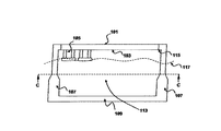
図1を参照するに、上部甲板101及び下部甲板103を有するプラットホームに取り付けられた多数の波エネルギー変換機構105を備える、波を電気に変換するために水域に配置される構造物の正面図が示されている。この構造物は、該構造物を水に浮かせ、支持するために水中で静止する浮体を含む。この浮体は、バラスト水のための底部殻109と、複数の側部殻107とを有する二重層殻体を含む。
Referring to FIG. 1, a front view of a structure disposed in a body of water with a number of wave
前記底部殻及び前記側部殻は、開口を有する吸い込み口113を形成する。前記開口は、波が通過することができるように吸い込み口113の各端部に設けられている。
The bottom shell and the side shell form a
吸い込み口113は、U字状の断面を有し、前記構造物の上部のプラットホーム101から下方に伸びる垂直な側部殻107は、前記構造物の底部の水平な底部殻109と一体的に結合している。
The
複数の浮台が、吸い込み口113を通過する波によって押されるように該吸い込み口の内側に設けられている。複数の固定保持部材が、前記浮台を吸い込み口113内部で定位置に保持するために設けられている。波及び水は、吸い込み口113の一方の開口から流入し、その他方の開口から流出する。
A plurality of floats are provided inside the suction port so as to be pushed by the waves passing through the
底部殻109は、前記構造物が波の運動によって運び去られること、移動させられること及び上下にうねることを防ぐべく、前記構造物を基本的に安定させるために巨大な緩衝器として作用するように広い平面を有する。バラスト水施設により、前記浮台は、常に水面117で維持される。本発明によれば、前記構造物は、海、大洋等の底に強固に固定する必要はないが、浮いて、潮流にのって上下しなければならない。
The
前記プラットホームは、複数のエネルギー変換システムを安全に収納し、保持するように設けられた上部甲板101及び下部甲板103を含む複数の甲板を有する。各システムは、発電のために波エネルギー変換機構に直接接続されている。
The platform has a plurality of decks including an
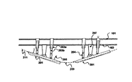
図2を参照するに、複数の浮台201は、波エネルギー変換機構105(図1)に取り付けられている。浮台201は、一連の接近する波の頂点により押されるとき、連続したロッキング運動ができるように前記浮台の前部と後部との間に位置する固定点で個別に旋回する。最初に、前記前部が持ち上げられ(211)、同時に前記後部が下がる(209)。次に、波の頂点が前記後部の方へ動くとき、該後部は持ち上げられ、一方で前記前部は下がる。この前部及び後部のロッキング運動は、1つのサイクルの平均として各15秒程度で延々と繰り返される。少なくとも1つの保持部材207が、浮台201が常に水面にあるように前記浮台を定位置に保持する。
Referring to FIG. 2, the plurality of
浮台201がピボットの周りで揺れ動くとき、複数の浮台201の並進運動は、液圧ポンプのピストン203bを上下に押圧するクランク機構204により往復運動又は回転運動に変換される。少なくとも2つのクランク機構204が、前記往復運動が前記クランク機構間で交互に生じるように、ピボット間に前後に設けられる。このように、浮台201の前記ロッキング運動は、効果的に利用される。
When the floating
液圧システムは、該液圧システムがクリーンで効率的なエネルギー変換システムであるので、昇圧が蓄圧器の使用により一様にされ、結果として発電のために制御された速度及びトルクがもたらされるような発電システムとして選択される。 The hydraulic system is such that the boost is made uniform through the use of an accumulator, resulting in a controlled speed and torque for power generation, since the hydraulic system is a clean and efficient energy conversion system. Selected as a power generation system.
浮台201の長さは、波の頂点間の距離の半分を超えてはならない。各浮台の前部及び後部の長さ及び重さは、前記浮台が該浮台の平衡位置に容易に戻ることができるように等しい。
The length of the
図2を参照するに、浮台201の長さは、2つの連続する頂点211の間の距離の半分である。波が吸い込み口113を前部から後部へ通り抜けるとき、浮台201の前部は、波の頂点により持ち上げられ、浮台201の後部は、先行する波の谷に沈む。したがって、各浮台の前部又は後部のロッキング運動がピボットの周りで連続して交互に生ずる。前記ピボットに取り付けられた浮台の長さの半分が持ち上げられるレバー動作の機械効率を計算することにより、途方もない量の液力が、この押圧運動に抵抗する液圧ポンプに転送される。波力のほとんどは、前記液圧ポンプの抵抗に打ち勝つために使用される。
Referring to FIG. 2, the length of the floating
浮台201は、できるだけ多くの波のエネルギーを獲得するために広い平坦な底面を有する。さらに、各浮台の前面は、エネルギーを含んだ波の到来方向に対して直角でなければならない。浮台201の前部は、傾斜面301を有する。さらに、障壁205が、激しい波から前記保持部材及び前記エネルギー変換機構を守るために設けられている。
The
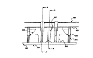
点検目的のために、浮台201は、固定できるように構成されている。浮台201は、図3に示すように、固定アーム303を受けるように固定柱304を設けることにより固定される。点検の間、固定アーム303は、浮台201と連結するために前記プラットホームから展開される。固定アーム303は、より長い保持部材により距離が離れた浮台201と連結するために固定アーム303から延長可能な柱をさらに備える。上部甲板101と距離をおいた下部甲板103は、人が該下部甲板の上を歩くことができ、波エネルギー変換機構105及び前記エネルギー変換システムに近づくことができる。
For inspection purposes, the
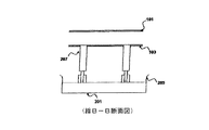
図4aは、浮台201上の波エネルギー変換機構105の配置を示す浮台の正面図である。一連の往復運動を発電に変えるために、複数の波エネルギー変換機構105が、浮台201上に設けられている。図4bに示すように、一対の保持部材207が浮台201を保持するように設けられている。
FIG. 4 a is a front view of the buoy that shows the arrangement of the wave
図5に示すように、上部甲板101は、開放領域である。この開放領域は、ヘリポート507と、貯蔵所511と、クレーンが置かれる領域513と、変電設備515と、要員詰所509とを備える。前記エネルギー変換システムは、蓄圧器501と、高圧液圧パイプ500と、発電機502と、液圧モータ503と、低圧液圧パイプ506と、液体冷却器504と、液体タンク505とを含む。
As shown in FIG. 5, the
前記エネルギー変換システムは、上部甲板101と下部甲板103との間に設けられた空間内部に取り付けられている。アンビリカルケーブルが、変電設備515から陸上局へ発電した電気を送電するために設けられている。
The energy conversion system is mounted in a space provided between the
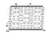
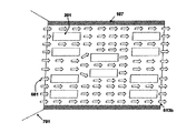
浮台201は、吸い込み口113を通過する波を利用するために該吸い込み口の内部に設けられている。より多くの浮台201は、より多くの往復運動を発生させ、変換させることができ、より多くの電気を発電することができることを意味する。浮台201は、第1の開口613aに流入し、第2の開口613bから流出する波及び水流プロファイル601を効果的に利用するように配置されている。図6に示すように、複数の浮台201は、対で配置され、複数の対は互いに平行で直列に配置されている。次の列は、第1の列より多く又はより少ない対を有する。図6に示すように、前記第1の列は、第2の列より多くの浮台201の対を有し、前記第2の列は、第3の列より少ない浮台201の対を有する。
The
漏斗状延長部が、図7に示すように、より多くの強力な波が吸い込み口113に流入できるように該吸い込み口前面のより多くの波を集めるために前面の開口613aに設けられている。
A funnel-like extension is provided in the front opening 613a to collect more waves in front of the inlet, so that more powerful waves can flow into the
101 上部甲板
103 下部甲板
105 波エネルギー変換機構
107 側部殻
109 底部殻
113 吸い込み口
201 浮台
203b 液圧ポンプのピストン
204 クランク機構
205 障壁
207 保持部材
209 波
211 波の頂点
301 傾斜面
303 固定アーム
304 固定柱
500 高圧液圧パイプ
501 蓄圧器
502 発電機
503 液圧モータ
504 液体冷却器
505 液体タンク
506 低圧液圧パイプ
507 ヘリポート
509 要員詰所
511 貯蔵庫
515 変電設備
701 漏斗状延長部
DESCRIPTION OF
Claims (22)
前記構造物を支持する浮体であって、水バラストのための底部殻及び側部殻を含む二重層殻によって画定される吸い込み口を形成する浮体と、
波の運動を連続した往復運動に変換する複数の波エネルギー変換機構と、
発電するために該波エネルギー変換機構の前記往復運動と共働する複数のエネルギー変換システムと、
前記側部殻に接続されて前記波エネルギー変換機構及び前記エネルギー変換システムを定位置で収納するプラットホームと
を含み、
前記波エネルギー変換機構は、波とともに動くことができる浮台を含み、
前記吸い込み口は、水が該吸い込み口に流入し、通過できるように一端部と他端部とに開口を有し、
各浮台は、前記プラットホームから延びる保持部材により前記吸い込み口の中に保持され、かつ、前記浮台の前部と後部との間に位置する固定点を中心に旋回され、波に押されたときに前記浮台が前記旋回の中心のまわりで上下に揺れ動く、構造物。 A structure that converts wave energy into electricity and is located in water such as the ocean and ocean,
A floating body that supports the structure, forming a suction port defined by a double layer shell including a bottom shell and a side shell for water ballast ;
A plurality of wave energy conversion mechanisms that convert wave motion into continuous reciprocating motion;
A plurality of energy conversion systems cooperating with the reciprocating motion of the wave energy conversion mechanism to generate electricity;
A platform connected to the side shell to house the wave energy conversion mechanism and the energy conversion system in place ;
Before KIHA energy conversion mechanism includes a pontoon which can move with the waves,
The suction port has openings at one end and the other end so that water can flow into the suction port and pass through.
Each buoy is held in the suction port by a holding member extending from the platform, and is swung around a fixed point located between the front and rear of the buoy and pushed by a wave the pontoon is rather dynamic shaking up and down about the center of the orbiting, structure when.
液体が前記高圧液圧パイプを介して前記ピストン、前記蓄圧器、及び前記液圧モータを流れ、その後前記低圧液圧パイプを介して前記液体冷却器及び前記液体タンクを流れて前記ピストンに戻り、
前記液圧モータによって前記発電機が駆動される、請求項5又は6に記載の構造物。 The energy conversion system includes a high pressure hydraulic pipe, a low pressure hydraulic pipe, a generator, a hydraulic motor, a pressure accumulator, a liquid tank, and a liquid cooler,
Liquid flows through the high pressure hydraulic pipe through the piston, the accumulator, and the hydraulic motor, and then through the low pressure hydraulic pipe through the liquid cooler and the liquid tank to return to the piston;
The structure according to claim 5 or 6, wherein the generator is driven by the hydraulic motor .
ヘリポート、クレーン、貯蔵庫、要員詰所、及び電気を陸上に送電する変電設備のための領域が設けられた上部甲板と、
要員が前記波エネルギー変換機構に歩いて近づくことができる下部甲板と
を有する、請求項8に記載の構造物。 The platform is
An upper deck with areas for heliports, cranes, storage, staffing stations, and substations that transmit electricity to land,
The structure according to claim 8, further comprising: a lower deck on which personnel can walk and approach the wave energy conversion mechanism.
平らな底面と、
波の頂点と向かい合う、該浮台の前部にある傾斜面と
を有する、請求項4から12のいずれか1項に記載の構造物。 The float is
A flat bottom,
The structure according to any one of claims 4 to 12 , further comprising an inclined surface at a front portion of the buoy that faces a wave apex.
海、大洋等の水域に構造物を浮かせることと、
水及び波が通過できるように、前記構造物に開口端及び側部殻を備えた吸い込み口を形成することと、
前記吸い込み口の中で固定保持部材から浮台を懸架して、前記吸い込み口の中で波に押されたときに前記浮台が旋回中心のまわりで上下に揺れ動くようにすることにより波の運動を往復運動に変換することと、
前記吸い込み口を通過する波に前記波エネルギー変換機構が押されるように前記構造物を水平に保つことと
を含み、
前記構造物を浮かせることは、底部殻及び前記側部殻を含む二重層殻を使用することである、方法。 A method of converting wave energy into electricity,
Floating structures in the waters of the ocean, ocean, etc.
Forming a suction opening with an open end and a side shell in the structure so that water and waves can pass through;
Wave motion by suspending a buoy from a fixed holding member in the suction port and causing the buoy to swing up and down around the swivel center when pushed by the wave in the suction port and Rukoto to convert the reciprocating motion,
Look containing a keeping said structure horizontally to the wave energy conversion mechanism is pushed waves passing through the suction port,
Floating the structure is to use a double layer shell that includes a bottom shell and the side shell .
Applications Claiming Priority (3)
| Application Number | Priority Date | Filing Date | Title |
|---|---|---|---|
| MYPI20081889 | 2008-06-02 | ||
| MYPI20081889A MY143137A (en) | 2008-06-02 | 2008-06-02 | Wave energy conversion plant |
| PCT/MY2009/000066 WO2009148296A2 (en) | 2008-06-02 | 2009-06-01 | Wave energy conversion plant |
Publications (3)
| Publication Number | Publication Date |
|---|---|
| JP2011522169A JP2011522169A (en) | 2011-07-28 |
| JP2011522169A5 JP2011522169A5 (en) | 2013-01-31 |
| JP5541465B2 true JP5541465B2 (en) | 2014-07-09 |
Family
ID=43779454
Family Applications (1)
| Application Number | Title | Priority Date | Filing Date |
|---|---|---|---|
| JP2011512397A Expired - Fee Related JP5541465B2 (en) | 2008-06-02 | 2009-06-01 | Wave energy conversion equipment |
Country Status (9)
| Country | Link |
|---|---|
| US (1) | US9018785B2 (en) |
| JP (1) | JP5541465B2 (en) |
| KR (1) | KR101270462B1 (en) |
| CN (1) | CN102057156A (en) |
| AU (1) | AU2009255823B2 (en) |
| DE (1) | DE112009001343T5 (en) |
| GB (1) | GB2472753B (en) |
| MY (1) | MY143137A (en) |
| WO (1) | WO2009148296A2 (en) |
Families Citing this family (22)
| Publication number | Priority date | Publication date | Assignee | Title |
|---|---|---|---|---|
| ES2375005B1 (en) * | 2009-04-20 | 2013-01-24 | Manuel Torres Martínez | POWER STATION ON A SUBMERGED FLOATING PLATFORM. |
| US8415819B2 (en) * | 2009-08-06 | 2013-04-09 | ISC8 Inc. | Energy harvesting buoy |
| WO2011079911A2 (en) * | 2009-12-30 | 2011-07-07 | Robert Bosch Gmbh | Wave power plant |
| KR101089421B1 (en) | 2010-04-02 | 2011-12-07 | 우정택 | Wave power generation system |
| KR101086824B1 (en) | 2010-04-15 | 2011-11-24 | 삼성중공업 주식회사 | Wave power generation unit and wave power generation ship having the same |
| PT105792A (en) | 2011-07-05 | 2013-01-07 | Omnidea Lda | SUBMERSAL PLATFORM |
| GB2496856B (en) * | 2011-11-22 | 2017-11-01 | Frederick Mann David | Wave energy inertia device |
| US8629572B1 (en) | 2012-10-29 | 2014-01-14 | Reed E. Phillips | Linear faraday induction generator for the generation of electrical power from ocean wave kinetic energy and arrangements thereof |
| US9624900B2 (en) | 2012-10-29 | 2017-04-18 | Energystics, Ltd. | Linear faraday induction generator for the generation of electrical power from ocean wave kinetic energy and arrangements thereof |
| US10011910B2 (en) | 2012-10-29 | 2018-07-03 | Energystics, Ltd. | Linear faraday induction generator for the generation of electrical power from ocean wave kinetic energy and arrangements thereof |
| CN105221333A (en) * | 2015-10-16 | 2016-01-06 | 浙江海洋学院 | A kind of integrated vertical-axis tide energy power generation system |
| US10767618B2 (en) * | 2016-04-24 | 2020-09-08 | The Regents Of The University Of California | Submerged wave energy converter for shallow and deep water operations |
| CN105888961B (en) * | 2016-05-17 | 2017-11-14 | 上海理工大学 | A kind of wave device and fluctuation TRT |
| US9957018B1 (en) * | 2017-02-07 | 2018-05-01 | Cvetan Angeliev | System for wave amplifying, wave energy harnessing, and energy storage |
| US11002243B2 (en) | 2017-04-24 | 2021-05-11 | The Regents Of The University Of California | Submerged wave energy converter for deep water operations |
| US10876514B2 (en) * | 2017-10-17 | 2020-12-29 | Dinh Chinh Nguyen | Ocean wave energy exploiting and storing device |
| CN108001662A (en) * | 2018-01-03 | 2018-05-08 | 冯政尧 | A kind of auxiliary braking system of ship |
| US10047717B1 (en) | 2018-02-05 | 2018-08-14 | Energystics, Ltd. | Linear faraday induction generator for the generation of electrical power from ocean wave kinetic energy and arrangements thereof |
| CN109139342A (en) * | 2018-11-01 | 2019-01-04 | 中国石油大学(华东) | A kind of new and effective ocean marine vessel wave energy generating set |
| US10927807B1 (en) | 2020-03-10 | 2021-02-23 | Robert Bidgood | Wave-powered electricity generator |
| CN112240263B (en) * | 2020-09-24 | 2022-11-18 | 南方科技大学 | Self-generating buoy system |
| CN114320719B (en) * | 2021-12-16 | 2023-04-18 | 广东工业大学 | Energy catamaran power generation device and power generation method thereof |
Family Cites Families (26)
| Publication number | Priority date | Publication date | Assignee | Title |
|---|---|---|---|---|
| US1930958A (en) * | 1932-02-24 | 1933-10-17 | Osborne H Parsons | Wave motor |
| JPS50108439A (en) * | 1974-02-05 | 1975-08-26 | ||
| JPS534356Y2 (en) * | 1974-10-28 | 1978-02-03 | ||
| JPS5442843A (en) * | 1977-09-12 | 1979-04-05 | Sanwa Setsubi Kogyo Kk | Gas spraying device for purifying water |
| US4184336A (en) * | 1978-05-08 | 1980-01-22 | Joseph Benedetto | Water wave energy transducer |
| JPS5557670A (en) * | 1978-10-24 | 1980-04-28 | Yasuhiro Manabe | Multi-magnet device for generating electricity by utilizing vertical motion of wave |
| JPS55160967A (en) * | 1979-05-30 | 1980-12-15 | Yasuhiro Manabe | Multimagnet electric generator employing vertical motion of wave |
| US4622471A (en) * | 1981-10-01 | 1986-11-11 | Schroeder Warren C | Ocean wave hydro-electric generator facility |
| JPS59206680A (en) * | 1983-05-10 | 1984-11-22 | Nippon Zosen Shinko Zaidan | Wave-energy-electric power generation device equipped with floating body |
| JPS6119679U (en) * | 1984-07-10 | 1986-02-04 | 武彦 佐藤 | Storage type wave power generation device |
| US4622473A (en) * | 1984-07-16 | 1986-11-11 | Adolph Curry | Wave-action power generator platform |
| US6327994B1 (en) * | 1984-07-19 | 2001-12-11 | Gaudencio A. Labrador | Scavenger energy converter system its new applications and its control systems |
| SU1532722A1 (en) | 1987-12-31 | 1989-12-30 | Н. М. Абдулов | Wave-operated power plant |
| US4931662A (en) * | 1988-01-26 | 1990-06-05 | Burton Lawrence C | Wave energy system |
| WO1990004718A1 (en) * | 1988-10-18 | 1990-05-03 | Gordan Henry Turner | Wave power conversion |
| CA2196224C (en) * | 1997-01-29 | 2003-07-01 | Gerald John Vowles | Wave energy generator |
| JPH11159435A (en) * | 1997-10-15 | 1999-06-15 | Kenchin Chin | Wave activated power generating method and device thereof |
| JP2002332946A (en) * | 2001-05-02 | 2002-11-22 | Tomiji Watabe | High output wave activated power generation buoy |
| US20030019207A1 (en) * | 2001-07-30 | 2003-01-30 | Parker David Joseph | Wave driven power generation system |
| ITBA20020047A1 (en) * | 2002-12-17 | 2004-06-18 | Enertec Aktiegesellschaft Ag | METHOD OF REALIZATION OF A SUBMERSIBLE PUSH-PLATFORM LOCKED FOR THE PRODUCTION OF ELECTRICITY FROM THE WIND IN THE OPEN SEA AND OF MARICULTURE PRODUCTS |
| KR100524525B1 (en) * | 2003-04-19 | 2005-11-01 | 임명식 | An Electric Generating Apparatus Using Wave Force |
| NO20032882D0 (en) * | 2003-06-23 | 2003-06-23 | Fobox As | Bölgekraftverk |
| US7199481B2 (en) * | 2003-11-07 | 2007-04-03 | William Walter Hirsch | Wave energy conversion system |
| ITRM20040228A1 (en) * | 2004-05-10 | 2004-08-10 | Maria Giuliana Irti | MODULAR SYSTEM FOR THE PRODUCTION OF ELECTRICITY FROM WAVY MOTORCYCLES. |
| GB2436595B (en) * | 2006-03-29 | 2011-04-27 | Peter Francis Kenny | Wavecycle generator |
| CN101074643A (en) * | 2006-05-17 | 2007-11-21 | 温秀生 | Wave power generator |
-
2008
- 2008-06-02 MY MYPI20081889A patent/MY143137A/en unknown
-
2009
- 2009-06-01 KR KR1020107029401A patent/KR101270462B1/en not_active IP Right Cessation
- 2009-06-01 US US12/994,871 patent/US9018785B2/en not_active Expired - Fee Related
- 2009-06-01 WO PCT/MY2009/000066 patent/WO2009148296A2/en active Application Filing
- 2009-06-01 CN CN2009801204446A patent/CN102057156A/en active Pending
- 2009-06-01 JP JP2011512397A patent/JP5541465B2/en not_active Expired - Fee Related
- 2009-06-01 DE DE112009001343T patent/DE112009001343T5/en not_active Ceased
- 2009-06-01 GB GB1021695.0A patent/GB2472753B/en not_active Expired - Fee Related
- 2009-06-01 AU AU2009255823A patent/AU2009255823B2/en not_active Ceased
Also Published As
| Publication number | Publication date |
|---|---|
| GB2472753B (en) | 2012-11-28 |
| GB201021695D0 (en) | 2011-02-02 |
| GB2472753A (en) | 2011-02-16 |
| WO2009148296A3 (en) | 2010-04-22 |
| MY143137A (en) | 2011-03-15 |
| CN102057156A (en) | 2011-05-11 |
| JP2011522169A (en) | 2011-07-28 |
| WO2009148296A2 (en) | 2009-12-10 |
| US20110074160A1 (en) | 2011-03-31 |
| US9018785B2 (en) | 2015-04-28 |
| KR20110025660A (en) | 2011-03-10 |
| AU2009255823B2 (en) | 2014-01-16 |
| AU2009255823A1 (en) | 2009-12-10 |
| KR101270462B1 (en) | 2013-05-31 |
| DE112009001343T5 (en) | 2011-07-07 |
Similar Documents
| Publication | Publication Date | Title |
|---|---|---|
| JP5541465B2 (en) | Wave energy conversion equipment | |
| JP2011522169A5 (en) | ||
| US7930885B2 (en) | Water wave-based energy transfer system | |
| US9309860B2 (en) | Wave energy conversion device | |
| US9074577B2 (en) | Wave energy converter system | |
| US7339285B2 (en) | Hydroelectric wave-energy conversion system | |
| US20080054640A1 (en) | Air pump in float | |
| US20130009402A1 (en) | Wave-energy converter | |
| US7994651B2 (en) | Apparatus for converting the energy of waves on a body of water | |
| CN109477665A (en) | Solar power station | |
| CN102149918A (en) | Wave powered generator | |
| JP2009542964A (en) | Wave energy converter | |
| JP7168272B2 (en) | Complementary deep-sea multi-energy integrated platform for power generation, production, livelihoods and exploration | |
| CN105971813A (en) | Wave energy power station structure integrating bulwark function | |
| CN104033327A (en) | U-shaped tube type wave power generation device adopting double floaters | |
| JP2009533600A (en) | Multiple use and complementary conversion of sea wave energy | |
| WO2015014241A1 (en) | Water pressure type wave energy converter | |
| CN102834604A (en) | Device for recovering swell energy | |
| KR20110059880A (en) | Apparatus for converting ocean wave energy | |
| CN104265551A (en) | Nearshore sea mushroom type wave energy power generation device | |
| CN101327969A (en) | Floating island having ocean energy electricity generating and seawater desalination functions | |
| RU2559956C1 (en) | Wave energy converter (versions) | |
| CN205841081U (en) | A kind of structure having breakwater function floating wave energy power station concurrently | |
| CN210531046U (en) | Floating breakwater-ocean energy device integrated system | |
| RU2152536C1 (en) | Wave energy converter |
Legal Events
| Date | Code | Title | Description |
|---|---|---|---|
| A524 | Written submission of copy of amendment under section 19 (pct) |
Free format text: JAPANESE INTERMEDIATE CODE: A524 Effective date: 20120530 |
|
| A621 | Written request for application examination |
Free format text: JAPANESE INTERMEDIATE CODE: A621 Effective date: 20120530 |
|
| A521 | Written amendment |
Free format text: JAPANESE INTERMEDIATE CODE: A523 Effective date: 20121206 |
|
| A871 | Explanation of circumstances concerning accelerated examination |
Free format text: JAPANESE INTERMEDIATE CODE: A871 Effective date: 20121206 |
|
| A975 | Report on accelerated examination |
Free format text: JAPANESE INTERMEDIATE CODE: A971005 Effective date: 20130123 |
|
| A131 | Notification of reasons for refusal |
Free format text: JAPANESE INTERMEDIATE CODE: A131 Effective date: 20130528 |
|
| A977 | Report on retrieval |
Free format text: JAPANESE INTERMEDIATE CODE: A971007 Effective date: 20130531 |
|
| A521 | Written amendment |
Free format text: JAPANESE INTERMEDIATE CODE: A523 Effective date: 20130718 |
|
| A131 | Notification of reasons for refusal |
Free format text: JAPANESE INTERMEDIATE CODE: A131 Effective date: 20131015 |
|
| A521 | Written amendment |
Free format text: JAPANESE INTERMEDIATE CODE: A523 Effective date: 20140107 |
|
| TRDD | Decision of grant or rejection written | ||
| A01 | Written decision to grant a patent or to grant a registration (utility model) |
Free format text: JAPANESE INTERMEDIATE CODE: A01 Effective date: 20140401 |
|
| A61 | First payment of annual fees (during grant procedure) |
Free format text: JAPANESE INTERMEDIATE CODE: A61 Effective date: 20140422 |
|
| R150 | Certificate of patent or registration of utility model |
Ref document number: 5541465 Country of ref document: JP Free format text: JAPANESE INTERMEDIATE CODE: R150 |
|
| R250 | Receipt of annual fees |
Free format text: JAPANESE INTERMEDIATE CODE: R250 |
|
| LAPS | Cancellation because of no payment of annual fees |