JP5541423B1 - Steelmaking slag reduction treatment device and steelmaking slag reduction treatment system - Google Patents
Steelmaking slag reduction treatment device and steelmaking slag reduction treatment system Download PDFInfo
- Publication number
- JP5541423B1 JP5541423B1 JP2013550690A JP2013550690A JP5541423B1 JP 5541423 B1 JP5541423 B1 JP 5541423B1 JP 2013550690 A JP2013550690 A JP 2013550690A JP 2013550690 A JP2013550690 A JP 2013550690A JP 5541423 B1 JP5541423 B1 JP 5541423B1
- Authority
- JP
- Japan
- Prior art keywords
- slag
- steelmaking slag
- electric furnace
- hot
- molten
- Prior art date
- Legal status (The legal status is an assumption and is not a legal conclusion. Google has not performed a legal analysis and makes no representation as to the accuracy of the status listed.)
- Active
Links
- 239000002893 slag Substances 0.000 title claims abstract description 393
- 238000009628 steelmaking Methods 0.000 title claims abstract description 193
- 230000009467 reduction Effects 0.000 title claims abstract description 68
- XEEYBQQBJWHFJM-UHFFFAOYSA-N Iron Chemical compound [Fe] XEEYBQQBJWHFJM-UHFFFAOYSA-N 0.000 claims abstract description 142
- 239000000463 material Substances 0.000 claims abstract description 72
- 229910052742 iron Inorganic materials 0.000 claims abstract description 69
- 238000012545 processing Methods 0.000 claims description 20
- 238000010438 heat treatment Methods 0.000 abstract description 3
- 238000006722 reduction reaction Methods 0.000 description 62
- 239000010410 layer Substances 0.000 description 29
- 238000000034 method Methods 0.000 description 28
- 239000002994 raw material Substances 0.000 description 21
- 239000007789 gas Substances 0.000 description 16
- UQSXHKLRYXJYBZ-UHFFFAOYSA-N Iron oxide Chemical compound [Fe]=O UQSXHKLRYXJYBZ-UHFFFAOYSA-N 0.000 description 14
- 239000000203 mixture Substances 0.000 description 13
- 239000000843 powder Substances 0.000 description 12
- 229910000831 Steel Inorganic materials 0.000 description 10
- 239000003575 carbonaceous material Substances 0.000 description 10
- 239000010959 steel Substances 0.000 description 10
- OKTJSMMVPCPJKN-UHFFFAOYSA-N Carbon Chemical compound [C] OKTJSMMVPCPJKN-UHFFFAOYSA-N 0.000 description 9
- 239000003607 modifier Substances 0.000 description 9
- 229910052748 manganese Inorganic materials 0.000 description 8
- 229910052751 metal Inorganic materials 0.000 description 8
- 239000002184 metal Substances 0.000 description 8
- 238000007664 blowing Methods 0.000 description 7
- 239000000428 dust Substances 0.000 description 7
- 230000008569 process Effects 0.000 description 7
- NBIIXXVUZAFLBC-UHFFFAOYSA-N Phosphoric acid Chemical compound OP(O)(O)=O NBIIXXVUZAFLBC-UHFFFAOYSA-N 0.000 description 6
- 229910052799 carbon Inorganic materials 0.000 description 6
- 238000006243 chemical reaction Methods 0.000 description 6
- 238000002844 melting Methods 0.000 description 6
- 230000008018 melting Effects 0.000 description 6
- 229910052698 phosphorus Inorganic materials 0.000 description 6
- QVGXLLKOCUKJST-UHFFFAOYSA-N atomic oxygen Chemical compound [O] QVGXLLKOCUKJST-UHFFFAOYSA-N 0.000 description 5
- 229910052760 oxygen Inorganic materials 0.000 description 5
- 239000001301 oxygen Substances 0.000 description 5
- 229910018072 Al 2 O 3 Inorganic materials 0.000 description 4
- 238000002485 combustion reaction Methods 0.000 description 4
- 238000010586 diagram Methods 0.000 description 4
- 239000012530 fluid Substances 0.000 description 4
- 238000011946 reduction process Methods 0.000 description 4
- 239000007790 solid phase Substances 0.000 description 4
- 238000012360 testing method Methods 0.000 description 4
- 229910004298 SiO 2 Inorganic materials 0.000 description 3
- 229910000147 aluminium phosphate Inorganic materials 0.000 description 3
- 238000001816 cooling Methods 0.000 description 3
- 230000007423 decrease Effects 0.000 description 3
- 230000000694 effects Effects 0.000 description 3
- 238000007254 oxidation reaction Methods 0.000 description 3
- 238000004064 recycling Methods 0.000 description 3
- 238000002407 reforming Methods 0.000 description 3
- 238000010405 reoxidation reaction Methods 0.000 description 3
- 238000010079 rubber tapping Methods 0.000 description 3
- OAICVXFJPJFONN-UHFFFAOYSA-N Phosphorus Chemical compound [P] OAICVXFJPJFONN-UHFFFAOYSA-N 0.000 description 2
- 229910000805 Pig iron Inorganic materials 0.000 description 2
- 230000002159 abnormal effect Effects 0.000 description 2
- 229910002091 carbon monoxide Inorganic materials 0.000 description 2
- 238000005255 carburizing Methods 0.000 description 2
- 239000000919 ceramic Substances 0.000 description 2
- 230000008859 change Effects 0.000 description 2
- 239000003245 coal Substances 0.000 description 2
- 238000007796 conventional method Methods 0.000 description 2
- 230000001186 cumulative effect Effects 0.000 description 2
- 238000005261 decarburization Methods 0.000 description 2
- 238000002474 experimental method Methods 0.000 description 2
- 239000010881 fly ash Substances 0.000 description 2
- 238000002347 injection Methods 0.000 description 2
- 239000007924 injection Substances 0.000 description 2
- 230000007774 longterm Effects 0.000 description 2
- 238000012544 monitoring process Methods 0.000 description 2
- 239000012071 phase Substances 0.000 description 2
- 239000002686 phosphate fertilizer Substances 0.000 description 2
- 239000011574 phosphorus Substances 0.000 description 2
- XLYOFNOQVPJJNP-UHFFFAOYSA-N water Substances O XLYOFNOQVPJJNP-UHFFFAOYSA-N 0.000 description 2
- 238000005303 weighing Methods 0.000 description 2
- CWYNVVGOOAEACU-UHFFFAOYSA-N Fe2+ Chemical compound [Fe+2] CWYNVVGOOAEACU-UHFFFAOYSA-N 0.000 description 1
- 229910019142 PO4 Inorganic materials 0.000 description 1
- 238000003723 Smelting Methods 0.000 description 1
- 229910052782 aluminium Inorganic materials 0.000 description 1
- XAGFODPZIPBFFR-UHFFFAOYSA-N aluminium Chemical compound [Al] XAGFODPZIPBFFR-UHFFFAOYSA-N 0.000 description 1
- 238000013459 approach Methods 0.000 description 1
- 238000010923 batch production Methods 0.000 description 1
- 229910001570 bauxite Inorganic materials 0.000 description 1
- 239000011449 brick Substances 0.000 description 1
- ODINCKMPIJJUCX-UHFFFAOYSA-N calcium oxide Inorganic materials [Ca]=O ODINCKMPIJJUCX-UHFFFAOYSA-N 0.000 description 1
- 239000004568 cement Substances 0.000 description 1
- 239000010883 coal ash Substances 0.000 description 1
- 230000000052 comparative effect Effects 0.000 description 1
- 238000007865 diluting Methods 0.000 description 1
- 238000000605 extraction Methods 0.000 description 1
- 239000003337 fertilizer Substances 0.000 description 1
- 238000009472 formulation Methods 0.000 description 1
- 238000005469 granulation Methods 0.000 description 1
- 230000003179 granulation Effects 0.000 description 1
- 230000017525 heat dissipation Effects 0.000 description 1
- 238000004898 kneading Methods 0.000 description 1
- CPLXHLVBOLITMK-UHFFFAOYSA-N magnesium oxide Inorganic materials [Mg]=O CPLXHLVBOLITMK-UHFFFAOYSA-N 0.000 description 1
- 238000005259 measurement Methods 0.000 description 1
- 238000005272 metallurgy Methods 0.000 description 1
- 150000002739 metals Chemical class 0.000 description 1
- 238000012986 modification Methods 0.000 description 1
- 230000004048 modification Effects 0.000 description 1
- 230000003647 oxidation Effects 0.000 description 1
- 230000001590 oxidative effect Effects 0.000 description 1
- 239000010452 phosphate Substances 0.000 description 1
- NBIIXXVUZAFLBC-UHFFFAOYSA-K phosphate Chemical compound [O-]P([O-])([O-])=O NBIIXXVUZAFLBC-UHFFFAOYSA-K 0.000 description 1
- 238000002360 preparation method Methods 0.000 description 1
- 238000003672 processing method Methods 0.000 description 1
- 238000007670 refining Methods 0.000 description 1
- 238000000926 separation method Methods 0.000 description 1
- 238000010583 slow cooling Methods 0.000 description 1
- 239000007787 solid Substances 0.000 description 1
- 238000007711 solidification Methods 0.000 description 1
- 230000008023 solidification Effects 0.000 description 1
- 239000000161 steel melt Substances 0.000 description 1
- 230000001629 suppression Effects 0.000 description 1
- 239000002344 surface layer Substances 0.000 description 1
- 230000007704 transition Effects 0.000 description 1
- 239000002699 waste material Substances 0.000 description 1
Images


Classifications
-
- C—CHEMISTRY; METALLURGY
- C21—METALLURGY OF IRON
- C21C—PROCESSING OF PIG-IRON, e.g. REFINING, MANUFACTURE OF WROUGHT-IRON OR STEEL; TREATMENT IN MOLTEN STATE OF FERROUS ALLOYS
- C21C7/00—Treating molten ferrous alloys, e.g. steel, not covered by groups C21C1/00 - C21C5/00
- C21C7/0087—Treatment of slags covering the steel bath, e.g. for separating slag from the molten metal
-
- C—CHEMISTRY; METALLURGY
- C04—CEMENTS; CONCRETE; ARTIFICIAL STONE; CERAMICS; REFRACTORIES
- C04B—LIME, MAGNESIA; SLAG; CEMENTS; COMPOSITIONS THEREOF, e.g. MORTARS, CONCRETE OR LIKE BUILDING MATERIALS; ARTIFICIAL STONE; CERAMICS; REFRACTORIES; TREATMENT OF NATURAL STONE
- C04B5/00—Treatment of metallurgical slag ; Artificial stone from molten metallurgical slag
- C04B5/06—Ingredients, other than water, added to the molten slag or to the granulating medium or before remelting; Treatment with gases or gas generating compounds, e.g. to obtain porous slag
-
- C—CHEMISTRY; METALLURGY
- C21—METALLURGY OF IRON
- C21C—PROCESSING OF PIG-IRON, e.g. REFINING, MANUFACTURE OF WROUGHT-IRON OR STEEL; TREATMENT IN MOLTEN STATE OF FERROUS ALLOYS
- C21C5/00—Manufacture of carbon-steel, e.g. plain mild steel, medium carbon steel or cast steel or stainless steel
- C21C5/52—Manufacture of steel in electric furnaces
- C21C5/5229—Manufacture of steel in electric furnaces in a direct current [DC] electric arc furnace
-
- C—CHEMISTRY; METALLURGY
- C21—METALLURGY OF IRON
- C21C—PROCESSING OF PIG-IRON, e.g. REFINING, MANUFACTURE OF WROUGHT-IRON OR STEEL; TREATMENT IN MOLTEN STATE OF FERROUS ALLOYS
- C21C5/00—Manufacture of carbon-steel, e.g. plain mild steel, medium carbon steel or cast steel or stainless steel
- C21C5/52—Manufacture of steel in electric furnaces
- C21C5/527—Charging of the electric furnace
-
- F—MECHANICAL ENGINEERING; LIGHTING; HEATING; WEAPONS; BLASTING
- F27—FURNACES; KILNS; OVENS; RETORTS
- F27B—FURNACES, KILNS, OVENS, OR RETORTS IN GENERAL; OPEN SINTERING OR LIKE APPARATUS
- F27B19/00—Combinations of furnaces of kinds not covered by a single preceding main group
- F27B19/04—Combinations of furnaces of kinds not covered by a single preceding main group arranged for associated working
-
- F—MECHANICAL ENGINEERING; LIGHTING; HEATING; WEAPONS; BLASTING
- F27—FURNACES; KILNS; OVENS; RETORTS
- F27B—FURNACES, KILNS, OVENS, OR RETORTS IN GENERAL; OPEN SINTERING OR LIKE APPARATUS
- F27B3/00—Hearth-type furnaces, e.g. of reverberatory type; Tank furnaces
- F27B3/10—Details, accessories, or equipment peculiar to hearth-type furnaces
- F27B3/18—Arrangements of devices for charging
- F27B3/183—Charging of arc furnaces vertically through the roof, e.g. in three points
-
- F—MECHANICAL ENGINEERING; LIGHTING; HEATING; WEAPONS; BLASTING
- F27—FURNACES; KILNS; OVENS; RETORTS
- F27D—DETAILS OR ACCESSORIES OF FURNACES, KILNS, OVENS, OR RETORTS, IN SO FAR AS THEY ARE OF KINDS OCCURRING IN MORE THAN ONE KIND OF FURNACE
- F27D15/00—Handling or treating discharged material; Supports or receiving chambers therefor
-
- F—MECHANICAL ENGINEERING; LIGHTING; HEATING; WEAPONS; BLASTING
- F27—FURNACES; KILNS; OVENS; RETORTS
- F27D—DETAILS OR ACCESSORIES OF FURNACES, KILNS, OVENS, OR RETORTS, IN SO FAR AS THEY ARE OF KINDS OCCURRING IN MORE THAN ONE KIND OF FURNACE
- F27D3/00—Charging; Discharging; Manipulation of charge
- F27D3/14—Charging or discharging liquid or molten material
-
- C—CHEMISTRY; METALLURGY
- C21—METALLURGY OF IRON
- C21C—PROCESSING OF PIG-IRON, e.g. REFINING, MANUFACTURE OF WROUGHT-IRON OR STEEL; TREATMENT IN MOLTEN STATE OF FERROUS ALLOYS
- C21C5/00—Manufacture of carbon-steel, e.g. plain mild steel, medium carbon steel or cast steel or stainless steel
- C21C5/52—Manufacture of steel in electric furnaces
- C21C5/5229—Manufacture of steel in electric furnaces in a direct current [DC] electric arc furnace
- C21C2005/5235—Manufacture of steel in electric furnaces in a direct current [DC] electric arc furnace with bottom electrodes
-
- C—CHEMISTRY; METALLURGY
- C21—METALLURGY OF IRON
- C21C—PROCESSING OF PIG-IRON, e.g. REFINING, MANUFACTURE OF WROUGHT-IRON OR STEEL; TREATMENT IN MOLTEN STATE OF FERROUS ALLOYS
- C21C2300/00—Process aspects
- C21C2300/04—Avoiding foam formation
-
- Y—GENERAL TAGGING OF NEW TECHNOLOGICAL DEVELOPMENTS; GENERAL TAGGING OF CROSS-SECTIONAL TECHNOLOGIES SPANNING OVER SEVERAL SECTIONS OF THE IPC; TECHNICAL SUBJECTS COVERED BY FORMER USPC CROSS-REFERENCE ART COLLECTIONS [XRACs] AND DIGESTS
- Y02—TECHNOLOGIES OR APPLICATIONS FOR MITIGATION OR ADAPTATION AGAINST CLIMATE CHANGE
- Y02P—CLIMATE CHANGE MITIGATION TECHNOLOGIES IN THE PRODUCTION OR PROCESSING OF GOODS
- Y02P10/00—Technologies related to metal processing
- Y02P10/20—Recycling
Abstract
この製鋼スラグ還元処理装置は、電気炉を用いて熱間製鋼スラグを連続還元処理する製鋼スラグ還元処理装置であって、前記電気炉内に熱間製鋼スラグを流し込むスラグ供給容器と、前記電気炉に設けられるとともに、前記熱間製鋼スラグの還元によって生成された溶鉄上の溶融スラグ層を加熱する電極と、前記溶融スラグ層に、還元材を含む副原料を供給する副原料供給部と、前記スラグ供給容器を傾動させて前記熱間製鋼スラグの前記電気炉への流入量を調整する傾動装置と、を備える。
The steelmaking slag reduction treatment apparatus is a steelmaking slag reduction treatment apparatus that continuously reduces hot steelmaking slag using an electric furnace, the slag supply container for pouring hot steelmaking slag into the electric furnace, and the electric furnace An electrode for heating the molten slag layer on the molten iron generated by the reduction of the hot steelmaking slag, an auxiliary material supply unit for supplying an auxiliary material containing a reducing material to the molten slag layer, and A tilting device that tilts a slag supply container and adjusts an inflow amount of the hot steelmaking slag into the electric furnace.
Description
本発明は、製鋼工程で発生するスラグ(製鋼スラグ)を工業的規模で還元して有価成分を回収するとともに、製鋼スラグの性状を各種用途に適合するように改質する製鋼スラグ還元処理装置と製鋼スラグ還元処理システムに関する。 本願は、2012年6月27日に、日本に出願された特願2012−144473号と、2012年6月27日に、日本に出願された特願2012−144557号と、2012年10月25日に、日本に出願された特願2012−235692号とに基づき優先権を主張し、その内容をここに援用する。 The present invention relates to a steelmaking slag reduction treatment device that recovers valuable components by reducing slag (steelmaking slag) generated in a steelmaking process on an industrial scale, and modifies the properties of the steelmaking slag to suit various applications, The present invention relates to a steelmaking slag reduction treatment system. This application includes Japanese Patent Application No. 2012-144473 filed in Japan on June 27, 2012, Japanese Patent Application No. 2012-144557 filed in Japan on June 27, 2012, and October 25, 2012. We claim priority based on Japanese Patent Application No. 2012-235692 filed in Japan, the contents of which are incorporated herein by reference.
製鋼工程では、大量の製鋼スラグが発生する。製鋼スラグは、Fe、Mn等の金属成分、及び、P等を含むが、CaOを多量に含むことに起因する膨張・崩壊性のため、路盤材、骨材等への利用が制限されていた。しかし、近年、資源のリサイクルが積極的に推進されており、製鋼スラグから有価物を回収する方法が、これまで数多く開示されている。 A large amount of steelmaking slag is generated in the steelmaking process. Steelmaking slag contains metal components such as Fe and Mn, and P. However, due to expansion and disintegration caused by containing a large amount of CaO, its use for roadbed materials and aggregates has been limited. . However, in recent years, recycling of resources has been actively promoted, and many methods for recovering valuable materials from steelmaking slag have been disclosed so far.
特許文献1には、溶解炉に収納した鉄鋼溶湯に対し、鉄鋼溶製時に発生する鉄鋼スラグを加え、さらに、熱及び還元材を加えて、鉄鋼スラグを変成しつつ、Fe、Mn、及び、Pを溶湯に移行させて変成スラグを取得し、次に、溶湯中のMn及びPをスラグに移行させる鉄鋼スラグの処理方法が開示されている。しかし、該処理方法は、所要の成分組成のスラグを得るまで、数回のバッチ処理を連続的に行う必要があるので、作業効率が悪い。 In Patent Document 1, to steel melt stored in a melting furnace, steel slag generated at the time of steel melting is added, and further, heat and reducing material are added to transform the steel slag, while Fe, Mn, and A method for treating steel slag is disclosed in which P is transferred to a molten metal to obtain a metamorphic slag, and then Mn and P in the molten metal are transferred to the slag. However, this processing method is poor in work efficiency because it is necessary to continuously perform several batch processes until a slag having a required component composition is obtained.
特許文献2には、炭素含有率1.5wt%未満の鋼鉄浴に、酸化鉄含有率5wt%超の鋼鉄スラグを供給し、その後、炭素又は炭素キャリアを導入して、鋼鉄浴を炭化し、炭素含有率2.0wt%超の鋼鉄浴を得た後に、還元処理を行う方法が開示されている。
In
しかし、特許文献2の方法は、溶融スラグ装入時には溶鉄中のC濃度(炭素濃度)を1.5wt%未満として、多量のガス発生を抑制し、溶融還元実施時にはC濃度を2.0wt%超に上昇させることで、所望の還元を行う。従って、脱炭昇熱と加炭還元を繰り返すため、バッチ処理となり、作業効率が悪い。なお、還元処理の実施時に、C濃度を2.0wt%超に上昇させていることから、特許文献2の方法は、主にスラグ−メタル間の反応により、還元反応を促進させているものと考えられる。
However, the method of
また、特許文献2の方法においては、炭材を、還元材として使用する他、熱源としても使用するので、排ガス量が増加する。その結果、熱効率の低下や、ダスト発生量の増加が想定される。
Moreover, in the method of
非特許文献1には、電気炉内に、製鋼スラグ粉、炭材粉、及び、スラグ改質材粉を中空電極から装入し、還元試験を行った結果が開示されている。しかし、非特許文献1の還元試験は、固化して粉砕した冷間の製鋼スラグを電気炉で処理する試験であるので、エネルギー原単位が大きい。 Non-Patent Document 1 discloses a result of a reduction test in which steelmaking slag powder, carbonaceous material powder, and slag modifier powder are charged from a hollow electrode in an electric furnace. However, since the reduction test of Non-Patent Document 1 is a test in which cold steelmaking slag that has been solidified and pulverized is processed in an electric furnace, the energy intensity is large.
また、特許文献3には、開放型直流電気炉中で、非鉄精錬で発生した溶融スラグを炭素質還元材で還元して、金属相とスラグ相に分離し、有価金属を回収する技術が開示されている。しかし、特許文献3の方法は、同様に、冷間スラグを処理対象物とする電気炉のバッチ処理であるので、エネルギー原単位が大きい。 Patent Document 3 discloses a technique for recovering valuable metals by reducing molten slag generated by non-ferrous refining with a carbonaceous reducing material in an open DC electric furnace, separating it into a metal phase and a slag phase. Has been. However, since the method of Patent Document 3 is also batch processing of an electric furnace using cold slag as a processing object, the energy intensity is large.
このように、スラグから有価成分を回収する方法は、いずれも、作業効率が悪いか、又は、エネルギー原単位が大きいという難点を抱えている。 As described above, any of the methods for recovering valuable components from slag has a problem that work efficiency is low or energy intensity is large.
前述したように、熱間製鋼スラグをバッチ処理でリサイクルする従来法は、作業効率が悪く、また、冷間製鋼スラグを溶融して資源としてリサイクルする従来法は、エネルギー原単位が高いという難点を抱えている。 As described above, the conventional method of recycling hot steelmaking slag by batch processing has poor work efficiency, and the conventional method of melting cold steelmaking slag and recycling it as a resource has the disadvantages of high energy intensity. I have it.
そこで、本発明は、作業効率が良好で、かつ、エネルギー原単位が低い手法として、製鋼スラグの還元処理を行い、有価成分を回収するとともに、製鋼スラグの性状を、各種用途に適合するように改質することを可能とする製鋼スラグ還元処理装置と製鋼スラグ還元処理システムを提供することを目的とする。 Therefore, the present invention is a method of reducing the steelmaking slag as a method with good working efficiency and low energy intensity, recovering valuable components and adapting the properties of the steelmaking slag to various applications. An object of the present invention is to provide a steelmaking slag reduction treatment apparatus and a steelmaking slag reduction treatment system that can be modified.
本発明の要旨は以下のとおりである。
(1)本発明の第一の態様は、電気炉を用いて熱間製鋼スラグを連続還元処理する製鋼スラグ還元処理装置であって、前記電気炉内に前記熱間製鋼スラグを流し込むスラグ供給容器と、前記電気炉に設けられるとともに、前記熱間製鋼スラグの還元によって生成された溶鉄上の溶融スラグ層を前記溶鉄と共に加熱する電極と、前記溶融スラグ層に、還元材を含む副原料を供給する副原料供給部と、前記スラグ供給容器を傾動させて前記熱間製鋼スラグの前記電気炉への流入量を調整する傾動装置と、を備え、かつ前記電気炉が固定式の密閉型電気炉である製鋼スラグ還元処理装置である。
(2)上記(1)に記載の製鋼スラグ還元処理装置では、前記密閉型電気炉が直流電気炉であってもよい。
(3)上記(1)、(2)のいずれか一項に記載の製鋼スラグ還元処理装置では、前記副原料供給部が、前記電極の内部に設けられた副原料供給管であってもよい。
(4)上記(1)〜(3)のいずれか一項に記載の製鋼スラグ還元処理装置では、前記スラグ供給容器に前記電気炉からの排ガスを排出する排気部が設けられていてもよい。
(5)本発明の第二の態様は、上記(1)に記載の還元処理装置を用いた製鋼スラグ還元処理システムであって、前記電極に供給された電力量を測定する測定部と;測定された前記電力量に基づいて還元し得る熱間製鋼スラグ量を算出するとともに、算出された前記還元し得る熱間製鋼スラグ量に基づいて所定の還元材量を算出する演算部と;前記還元し得る熱間製鋼スラグ量に対して、前記熱間製鋼スラグの前記電気炉への流入量が追従するように、前記傾動装置を駆動して、前記スラグ供給容器の傾斜角を調整するとともに、前記所定の還元材量が供給されるように前記副原料供給部からの前記副原料の供給量を調整する制御部と;を備える製鋼スラグ還元処理システムである。
The gist of the present invention is as follows.
(1) A first aspect of the present invention is a steelmaking slag reduction treatment apparatus for continuously reducing hot steelmaking slag using an electric furnace, wherein the hot steelmaking slag is poured into the electric furnace. And an electrode for heating the molten slag layer on the molten iron generated by the reduction of the hot steelmaking slag together with the molten iron, and an auxiliary material containing a reducing material to the molten slag layer. An auxiliary raw material supply unit, and a tilting device that tilts the slag supply container to adjust the inflow amount of the hot steelmaking slag into the electric furnace, and the electric furnace is a fixed sealed electric furnace This is a steelmaking slag reduction treatment apparatus.
(2) In the steelmaking slag reduction treatment apparatus described in (1 ) above, the sealed electric furnace may be a DC electric furnace.
(3) In the steelmaking slag reduction processing apparatus according to any one of (1) and (2) , the auxiliary material supply unit may be an auxiliary material supply pipe provided inside the electrode. .
(4) In the steelmaking slag reduction processing apparatus according to any one of (1) to (3) , an exhaust unit that exhausts exhaust gas from the electric furnace may be provided in the slag supply container.
(5) A second aspect of the present invention is a steelmaking slag reduction treatment system using the reduction treatment apparatus according to (1) above, and a measurement unit that measures the amount of electric power supplied to the electrode; A calculation unit that calculates the amount of hot steelmaking slag that can be reduced based on the amount of electric power that has been reduced, and that calculates a predetermined amount of reducing material based on the amount of hot steelmaking slag that can be reduced; The tilting device is driven to adjust the inclination angle of the slag supply container so that the inflow amount of the hot steelmaking slag into the electric furnace follows the amount of hot steelmaking slag that can be obtained, And a control unit that adjusts the supply amount of the auxiliary material from the auxiliary material supply unit so that the predetermined amount of reducing material is supplied.
上述の態様によれば、製鋼スラグを、低いエネルギー原単位で、セメント原料、土工材料、セラミック製品等の種々の用途に使用可能な材料に改質することができるとともに、Fe、Mn、及び、P等の有価元素を、溶鉄中に回収することができる。そして、Fe及びMnは、製鉄プロセスへリサイクルし、Pは、酸化処理を施すことによって燐酸肥料や燐酸原料として利用することができる。 According to the above-described aspect, the steelmaking slag can be modified into a material that can be used for various uses such as a cement raw material, an earthwork material, and a ceramic product with a low energy basic unit, and Fe, Mn, and Valuable elements such as P can be recovered in the molten iron. Then, Fe and Mn are recycled to the iron making process, and P can be used as a phosphate fertilizer or a phosphate raw material by performing an oxidation treatment.
本発明の目的である、作業効率が良好で、かつ、エネルギー原単位が低い手法を考えると、熱間製鋼スラグ(以下、単に製鋼スラグと呼ぶ場合がある)を用いることが、エネルギー原単位の低減の観点から有効である。しかし、熱間製鋼スラグを電気炉内に収容した溶鉄上に流入させる際、熱間製鋼スラグが溶鉄と急激に反応して突沸する現象(スラグフォーミング)が起き、これが激しくなるとスラグが電気炉から溢れ出る場合(オーバーフロー)がある。
前述したように、特許文献2の方法においては、突沸現象の防止策を、「溶鉄のC濃度の低減による反応速度の緩和」に求めているが、この方法では作業効率が悪い。Considering a method with good working efficiency and low energy intensity, which is the object of the present invention, it is possible to use hot steelmaking slag (hereinafter sometimes simply referred to as steelmaking slag). It is effective from the viewpoint of reduction. However, when hot steelmaking slag flows into molten iron contained in an electric furnace, a phenomenon occurs in which hot steelmaking slag rapidly reacts with molten iron and bumps (slag forming). There is a case of overflow (overflow).
As described above, in the method of
即ち、本発明においても、解決すべき課題として、同様の課題を抱えることになり、スラグ−メタル間の反応により、還元反応を促進させる還元炉(転炉等)では、溶鉄中のCが、スラグ中のFeOを還元する。このため、還元力を向上させるには、脱炭・加炭を繰り返し行う必要があり、その結果、作業効率は悪くなる。それ故、C濃度の低減策だけでは、充分な対策とは言えない。 That is, also in the present invention, as a problem to be solved, a similar problem will be held. In a reduction furnace (converter or the like) that promotes a reduction reaction by a reaction between slag and metal, C in the molten iron is Reduce FeO in slag. For this reason, in order to improve reduction power, it is necessary to repeat decarburization and carburizing, and as a result, work efficiency worsens. Therefore, it cannot be said that measures for reducing the C concentration alone are sufficient measures.
そこで、本発明者らは、鋭意検討したところ、電気炉では、還元反応は、スラグ−メタル間の反応よりも、スラグ中のFeOとCとの反応が支配的であることを実験により新たに知見した。それ故、若干の還元力の低下はあるが、1.5質量%程度の低いC濃度であっても、加炭なしで、スラグの還元処理を行うことが可能であり、作業効率を良好にできることが判明した。 Therefore, the present inventors have conducted intensive studies, and in an electric furnace, the reduction reaction is newly conducted by experiments that the reaction between FeO and C in the slag is more dominant than the reaction between the slag and the metal. I found out. Therefore, although there is a slight reduction in reducing power, it is possible to perform slag reduction treatment without carburizing even at a low C concentration of about 1.5% by mass, and work efficiency is improved. It turns out that you can.
したがって、電気炉を用いることにより、熱間製鋼スラグの流入時に突発的に起きるスラグフォーミングを抑制でき、スラグのオーバーフローを防止する対策の一つとなり得る。 Therefore, by using an electric furnace, slag forming that occurs suddenly when hot steelmaking slag flows in can be suppressed, which can be one of the measures to prevent slag overflow.
しかし、溶鉄中のC濃度が高い場合もあり得るため、溶鉄中のC濃度が高くても、作業効率が良好で、かつ、エネルギー原単位が低い方法を検討した。そこで、本発明者らは、電気炉を用いて、上記課題を解決する製鋼スラグ還元処理装置と製鋼スラグ還元処理システムを構築することを試みた。 However, since the C concentration in the molten iron may be high, even when the C concentration in the molten iron is high, a method with good working efficiency and low energy intensity was examined. Therefore, the present inventors tried to construct a steelmaking slag reduction treatment apparatus and a steelmaking slag reduction treatment system that solve the above-mentioned problems using an electric furnace.
その結果、熱間で流動性のある熱間製鋼スラグを、直接、電気炉に流入させる際、オーバーフローの発生を防止する具体的な手法として、
(a)熱間で流動性のある熱間製鋼スラグを、電気炉への流入量を調整できる装置に一旦収容してから、熱間製鋼スラグが電気炉内でオーバーフローしないように、電気炉への流入量を調整して流入させること、及び、
(b)溶鉄上に溶融スラグ層、好ましくは不活性な溶融スラグ層(還元スラグ層)を緩衝帯として予め形成し、その上に熱間製鋼スラグを流入させること、
の二点が溶融スラグの突沸現象を抑制し、オーバーフローを回避する点で好適であることが、実験的に見出された。As a result, as a concrete technique to prevent the occurrence of overflow when hot steelmaking slag, which is hot and fluid, flows directly into the electric furnace,
(A) Once hot hot steelmaking slag, which is hot and fluid, is temporarily stored in a device that can adjust the amount of inflow into the electric furnace, the hot steelmaking slag is transferred to the electric furnace so as not to overflow in the electric furnace. Adjusting the amount of inflow, and
(B) forming a molten slag layer on the molten iron, preferably an inert molten slag layer (reduced slag layer) in advance as a buffer zone, and allowing hot steelmaking slag to flow thereon;
These two points were experimentally found to be suitable for suppressing the bumping phenomenon of the molten slag and avoiding overflow.
また、
(c)溶融スラグに、予め、炭材を過剰に懸濁させて供給すること、及び、
(d)溶鉄のC濃度を3質量%以下に低減する(ただし、強還元を必要としない場合)こと、
も上記の(a)、(b)の方法と併用すると、オーバーフローを抑制する上で、より好適であることが見出された。Also,
(C) supplying the carbonaceous material in an excessively suspended state in advance to the molten slag; and
(D) reducing the C concentration of the molten iron to 3% by mass or less (provided that strong reduction is not required);
It has also been found that when combined with the above methods (a) and (b), it is more suitable for suppressing overflow.
本発明は、製鋼スラグを熱間で流動性のある間に還元処理を行えば、エネルギー原単位を低く抑制することができるとの技術思想に立脚するものである。
具体的には、本発明者らは、製鋼工程で発生する製鋼スラグを、熱間で流動性のある間に、電気炉に流入させて還元し、有価成分を回収するとともに、スラグを改質して、製鋼スラグを低いエネルギー原単位で資源化できると発想した。The present invention is based on the technical idea that if the steelmaking slag is subjected to a reduction treatment while it is hot and fluid, the energy intensity can be suppressed low.
Specifically, the present inventors reduced the steelmaking slag generated in the steelmaking process by flowing it into an electric furnace while it is hot and recovering valuable components and reforming the slag. The idea was that steelmaking slag could be recycled with low energy intensity.
以下、本発明の第1実施形態に係る製鋼スラグ還元処理装置100について説明する。
Hereinafter, the steelmaking slag
本実施形態に係る製鋼スラグ還元処理装置100の還元処理対象の製鋼スラグ(熱間製鋼スラグ6’)は、製鋼工程で発生したスラグであればよく、特定の製鋼スラグに限定されない。
The steelmaking slag (hot steelmaking slag 6 ') to be reduced by the steelmaking slag
また、熱間製鋼スラグ6’は、連続的又は間歇的に電気炉1内に流入させ得るに足る流動性を有していればよく、完全に溶融状態にある必要はない。熱間製鋼スラグ6’の固相率は、特に限定されないが、例えば、1400℃位で30%以下程度であれば、スラグは電気炉1に流入させ得る流動性を備えている。なお、固相率は、市販のソフトを用いて算出することができる。
Further, the
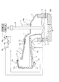
以下、図面に基づいて説明する。図1に、電気炉1と、傾動装置3aが設けられたスラグ供給容器9とを備える本発明の第1実施形態に係る製鋼スラグ還元処理装置100を示す。
Hereinafter, description will be given based on the drawings. FIG. 1 shows a steelmaking slag
電気炉1は、固定式の密閉型直流電気炉であり、上部電極2aと炉底電極2bとが鉛直方向に対をなす電極2を備えている。電気炉1の底部には、溶鉄5が収容され、溶鉄5の上には、スラグ供給容器9から供給された熱間製鋼スラグ6’を含む溶融スラグ6の層(溶融スラグ層)が形成されている。溶融スラグ層は、溶鉄5と共に電極2で加熱される。
本実施形態においては、溶融スラグ層に還元材を含む副原料を供給する副原料供給部14が、副原料供給管14aとして上部電極2aの内部に設けられている。
Electric furnace 1 is sealed DC electric furnace of a solid formulation, and the
In the present embodiment, an auxiliary material supply unit 14 for supplying an auxiliary material containing a reducing material to the molten slag layer is provided as an auxiliary
電気炉1の炉天井1cの左部には、熱間で流動性のある熱間製鋼スラグ6’をスラグ供給容器9から供給するスラグ供給部4が設けられている。電気炉1に外気(酸素又は酸素含有ガス)が侵入すると、溶融スラグ層の表面で酸化反応が起きて、溶融スラグ層の(Total Fe)が上昇し、還元力が低下する。
A slag supply unit 4 that supplies
ここで、図2に、電気炉1の炉壁に開口がある場合とない場合における溶融スラグ6の(Total Fe)(質量%)の経時推移を比較して示す。
Here, FIG. 2 shows a comparison of the time course of (Total Fe) (mass%) of the
還元材(炭材)を電気炉1内に吹き込み、溶融スラグ6を還元処理することにより、溶融スラグ6の(Total Fe)は減少するが(図中、炭材吹き込み期間、参照)、電気炉1の炉壁に開口部があると、空気が吸引されて電気炉1内が酸化性雰囲気となり、溶融スラグ6の表面で再酸化が起きる。このため、還元材(炭材)の吹込みが終了した後、再酸化の影響で、溶融スラグ6の(Total Fe)が増加する。
By blowing a reducing material (carbon material) into the electric furnace 1 and reducing the
一方、電気炉1の炉壁に開口部がないと、電気炉1内は還元雰囲気に維持されるので、溶融スラグ6の表面で再酸化は起きず、溶融スラグ6及び溶鉄5中のCによるFeOの還元反応が進行して、溶融スラグ6の(Total Fe)は減少し、所定の低水準に維持される。それ故、電気炉1は、外気が侵入しない密閉型とすることが好ましい。
また、スラグ供給容器9は、電気炉排ガスの排気経路となるように、スラグ供給容器9に排気部13が設けられている。On the other hand, if there is no opening in the furnace wall of the electric furnace 1, the inside of the electric furnace 1 is maintained in a reducing atmosphere. Therefore, reoxidation does not occur on the surface of the
Further, the
電気炉1内は、還元反応によって生じるCOガスと、供給される還元材(炭材)から生じるH2を主成分とする還元雰囲気となる。しかし、スラグ供給容器9を、電気炉排ガスの排気経路とする場合には、還元性雰囲気に維持されるため、溶融スラグ層の表面での酸化反応を防止できる。The electric furnace 1 has a reducing atmosphere mainly composed of CO gas generated by the reduction reaction and H 2 generated from the supplied reducing material (carbon material). However, when the
電気炉1の炉側壁1aには、出滓樋(図示なし)に溶融スラグ6を出滓する出滓孔7が設けられる。電気炉1の炉側壁1aとは反対側の炉側壁1bには、出銑樋(図示なし)に溶鉄5を出銑する出銑孔8が、出滓孔7のレベル(高さ)よりも下方に設けられている。なお、炉側壁1aと炉側壁1bの溶損を防止するために、出滓孔7と出銑孔8は同じ炉側壁近傍に設けないことが好ましく、炉側壁1aと炉側壁1bの溶損を防止可能な距離だけ離間していればよい。
The
なお、炉側壁1a、炉側壁1b、及び、炉天井1cは、ジャケット冷却又は散水冷却(図示なし)で冷却されている。
The
電気炉1は、電気炉1内に小塊鉄屑、DRI(Direct Reduced Iron)等の鉄原料を供給する原料供給装置(図示なし)を備えていてもよい。電気炉1で、小塊鉄屑、還元鉄、粉状ダスト等を溶解・還元して、溶鉄5を製造することができる。
The electric furnace 1 may include a raw material supply device (not shown) that supplies iron raw materials such as small iron scraps and DRI (Direct Reduced Iron) in the electric furnace 1. In the electric furnace 1,
電気炉1には、還元に必要な還元材、及び、溶融スラグ6の特性を改質する改質粉体等の副原料を供給する副原料供給部14が設けられている。この副原料供給部14は、図3に示す本発明の第2実施形態に係る製鋼スラグ還元処理装置200のように、電気炉1の炉天井1cに、炉天井1cを貫通するように設けられる副原料供給管14aであってもよい。副原料供給管14aから副原料(還元材、改質粉体等)を電気炉1内に供給すると、電気炉1内で発生するガス量が少ないので、副原料は、重力で溶融スラグ6の表面に落下して、溶融スラグ6と混合する。
The electric furnace 1 is provided with an auxiliary material supply unit 14 for supplying an auxiliary material such as a reducing material necessary for reduction and a modified powder for improving the characteristics of the
また、図1に示すように、電極2の上部電極2aを中空電極とし、中空部を副原料供給管14aとして使用してもよい。中空電極を用いれば、副原料(還元材、改質粉体等)を、直接、アークスポットに吹き込むことができる。
Moreover, as shown in FIG. 1, you may use the
また、図4に示す本発明の第3実施形態に係る製鋼スラグ還元処理装置300のように、電気炉1に副原料吹込ランス14bを設け、中空電極の中空部や副原料供給管14aを使わずに、飛散し易い粉体(副原料)を電気炉1内に供給しても良い。図4に示す態様では、電気炉1の炉天井1cに、炉天井1cを貫通するように副原料吹込ランス14bが設けられている。
Moreover, like the steelmaking slag
図3に示す製鋼スラグ還元処理装置200においては、副原料供給管14aを電極2の近くに配置しているが、副原料供給管14aは、電極2から離れた位置に配置してもよい。
また、電気炉1の炉天井1cに、副原料吹込ランス14bと副原料供給管14aとを併設してもよい。In the steelmaking slag
Further, the auxiliary
<スラグ供給容器>
スラグ供給容器9(図1、3、及び、4、参照)は、上壁11と下壁10から構成され、スラグ鍋(図示なし)から熱間製鋼スラグ6’の供給を受けるための開口部13aと、開口部13aを閉塞する蓋13bとを備える。スラグ供給容器9の上部には、排気部13が設けられてもよい。スラグ供給容器9の下壁10は、耐火物内張壁で構成され、上壁11は、水冷耐火物内張壁で構成されていることが好ましい。<Slag supply container>
The slag supply container 9 (see FIGS. 1, 3, and 4) is composed of an
スラグ供給容器9は、傾動軸zを中心に任意の角度に傾動可能である。したがって、電気炉1と連結されているスラグ供給部4から、熱間製鋼スラグ6’の電気炉1への流入量を調整することができる。
The
スラグ供給容器9が排気部13を備え、且つ、排気部13が集塵機(図示なし)に接続されている場合、スラグ供給容器9の雰囲気は、常に負圧状態になるため好ましい。このように負圧状態とすることで、電気炉1で発生したCO及びH2を含む高温排ガスは、スラグ供給部4からスラグ供給容器9内に浸入し、スラグ供給容器9の内部を排出径路として、排気部13から、排ガスダクト(図示なし)を経由して集塵機(図示なし)へ流出する。When the
この場合、スラグ供給容器9と電気炉1の連結部の隙間から外気が侵入しても、侵入した外気はスラグ供給容器9の内部へ流れるので、電気炉1内の雰囲気は、常に、高温の還元性雰囲気に維持される。一方、スラグ供給容器9の内部は、電気炉1の内部と同じように、高温の還元性雰囲気に維持されて、熱間製鋼スラグ6’は保温され、かつ、酸化されない。
In this case, even if the outside air enters through the gap between the connecting portion between the
スラグ供給容器9には、CO及びH2を含む電気炉排ガスに、酸素又は酸素含有ガスを吹き込むノズル12を設けてもよい。スラグ供給容器9内で、電気炉排ガスを燃焼させる場合、スラグ供給容器9内を高温に維持することができるため好ましい。これにより、熱間製鋼スラグ6’の凝固や、スラグ供給容器9の炉壁への付着を防止することができる。また、電気炉1へ流入させるために必要な流動性を熱間製鋼スラグ6’に付与することができる。The
排ガスの顕熱及び燃焼熱を利用しても、スラグ供給容器9内の温度が、熱間製鋼スラグがスラグ供給容器9の炉壁に付着しない温度まで上昇しない場合がある。この場合に備え、スラグ供給容器9に、燃焼バーナー12aを設けて、火炎を、スラグ供給容器9内に照射してもよい。
Even if the sensible heat and combustion heat of the exhaust gas are used, the temperature in the
また、スラグ供給容器9には、熱間製鋼スラグ6’をスラグ供給容器9内で改質するスラグ改質材を、熱間製鋼スラグ6’に添加するためのスラグ改質剤添加装置(図示なし)を配置してもよい。さらに、スラグ改質材を、燃焼バーナー12aを介してスラグ供給容器9内に溶融照射してもよい。
In addition, the
スラグ供給容器9には、スラグ供給容器9を、傾動軸zを中心として傾動し、熱間製鋼スラグの電気炉1への流入量を制御する傾動装置3aが配備されている。
次に、スラグ供給容器9による熱間製鋼スラグ6’の電気炉1への流入について説明する。The
Next, the inflow of
<熱間製鋼スラグの流入>
まず、手段(a)について、以下に詳述する。
(a)熱間で流動性のある熱間製鋼スラグを、電気炉1への流入量を調整できる装置に一旦収容してから、熱間で流動性のある熱間製鋼スラグが電気炉1内でオーバーフローしないように、電気炉1への流入量を調整して流入させる。<Inflow of hot steelmaking slag>
First, the means (a) will be described in detail below.
(A) Hot steelmaking slag having hot fluidity is once accommodated in a device capable of adjusting the amount of inflow into the electric furnace 1, and hot steelmaking slag having hot fluidity is contained in the electric furnace 1. In order to prevent overflow, the amount of flow into the electric furnace 1 is adjusted to flow in.
電気炉1内に、予め、相当量(例えば、100〜150トン程度)の溶鉄5を種湯として収容する。次に、電気炉1への電力供給速度に対して、還元し得る量の熱間製鋼スラグ6’を、スラグ供給容器9から、溶鉄5上の溶融スラグ6に供給し、溶融スラグ層を継続的に維持する。
In the electric furnace 1, a considerable amount (for example, about 100 to 150 tons) of
製鋼スラグ還元処理装置100,200,300において、熱間製鋼スラグ6’の電気炉1への流入態様は、傾動装置3aの駆動で、傾動軸zを中心としてスラグ供給容器9の傾動角を調整して、自在に選択することができる。
In the steelmaking slag
即ち、傾動装置3aで、スラグ供給容器9を、傾動軸zを中心として傾動させて、スラグ鍋(図示なし)から供給される熱間製鋼スラグ6’を貯留・保持し、また、貯留した熱間製鋼スラグ6’を、電気炉1内の溶鉄5上の溶融スラグ6の層に向けて、溶融スラグ6がフォーミングによって電気炉1からオーバーフローしないように、流入量を調整しつつ、連続的又は間歇的に流入させる。
That is, the
尚、熱間製鋼スラグ6’は、スラグ供給容器9で、一旦、貯留・保持するが、スラグ鍋からの供給量が少なく、スラグ供給容器9で、一旦、貯留・保持する必要がない場合は、スラグ供給容器9を一定の角度で固定して、スラグ樋として使用することもできる。
The
スラグ供給容器9を傾動させて、熱間製鋼スラグ6’を電気炉1内に流入させることにより、スラグ供給容器9内の熱間製鋼スラグ6’の高温表面層が更新されて、スラグ供給容器9内に残留する熱間製鋼スラグ6’への着熱効率が向上する。
By tilting the
熱間製鋼スラグ6’を間歇的に電気炉1内に流入させる場合、
(i)熱間製鋼スラグ6’の流入と中断を適宜繰り返しながら流入させる態様、又は、
(ii)所要量の熱間製鋼スラグ6’を、所定の時間間隔で、一括して流入させる態様
を採用し得る。When hot steelmaking slag 6 'is allowed to flow into the electric furnace 1 intermittently,
(I) A mode in which the inflow and interruption of hot steelmaking slag 6 'are repeated as appropriate, or
(Ii) A mode in which a required amount of hot steelmaking slag 6 'is allowed to flow in at a predetermined time interval may be employed.
熱間製鋼スラグ6’を電気炉1へ流入させているとき、流入速度が速すぎると、発生ガス量が一時的に増加してスラグフォーミング状態になり、スラグが電気炉1から溢れ出る(オーバーフロー)等の異常事態になりそうな場合がある。その場合は、スラグ供給容器9の傾動角を小さくして、熱間製鋼スラグ6’の電気炉1内への流入を一時停止するか、又は、還元材供給速度を増加させることが好ましい。
When
なお、熱間製鋼スラグ6’を電気炉1内へ流入させる際、溶融スラグ層の泡立ち状態(スラグフォーミング)が過激になりオーバーフロー等の異常事態に至るか否かは、常時、(1)監視カメラによる炉内状況及び炉外状況の監視、(2)サウンドメーターによる熱間製鋼スラグの挙動の監視、(3)マイクロ波照射による溶融スラグ表面レベルの監視、等で検知し、閾値を超えそうな場合、熱間製鋼スラグの電気炉1への流入量を調整することが好ましい。 In addition, when hot steelmaking slag 6 'is allowed to flow into the electric furnace 1, it is always monitored whether or not the foamed state (slag forming) of the molten slag layer becomes extreme and an abnormal situation such as overflow occurs (1). In-furnace condition and out-of-furnace condition with camera, (2) Hot steelmaking slag behavior monitoring with sound meter, (3) Molten slag surface level monitoring with microwave irradiation, etc. In such a case, it is preferable to adjust the amount of hot steelmaking slag flowing into the electric furnace 1.
溶融スラグ6がフォーミング状態になり、電気炉1から溢れ出る(オーバーフロー)のを予防する手段として、スラグ供給容器9からの熱間製鋼スラグ6’の流入量の調整(前記手段(a)、参照)の他に、以下の手段(b)があるため、(a)と(b)を併用してもよい。
As a means for preventing the
(b)溶鉄5の上のスラグとして、還元されたスラグを存在させることで緩衝帯としての機能を持たせ、これにより流入させる熱間製鋼スラグ6’のFeO濃度を希釈低減するとともに、熱間製鋼スラグ6’と溶鉄5との接触機会を低減する。
(B) As a slag on the
即ち、溶鉄5の上面に緩衝帯として還元処理後の溶融スラグ6を存在させることにより、この溶融スラグ6の(FeO)濃度が低減されているとともに、溶融スラグ6と溶鉄5との接触機会も低減できる。このため、溶融スラグ6のフォーミングを抑制し、結果的に、溶融スラグ6の電気炉1からのオーバーフローを防止することができる。
That is, by making the
熱間製鋼スラグ6’の電気炉1への流入量は、基本的には、電極2への供給電力量で決定される。即ち、製鋼スラグの還元処理に必要な電力原単位と、供給実績電力量に基づいて、連続的又は間歇的に流入させる熱間製鋼スラグ6’の流入量が計算される。
The amount of
熱間製鋼スラグ6’の流入速度は、長期的には、電極2への電力供給速度に合致させる必要があるが、短期的には、電極2への電力供給速度に合致させる必要はない。なぜなら、所定量の熱間製鋼スラグ6’を間歇的に電気炉1に流入させる場合、流入量は、短期的には、電極2への電力供給速度に合致していないからである。この場合、長期的には、電力供給速度に合致させることで問題はない。
The inflow speed of the
なお、熱間製鋼スラグの還元処理に必要な電力原単位は、反応熱および放熱を考慮した熱バランス計算により、求めることができる。但し、上記の電力原単位は、熱バランス計算による推定値であるため、その誤差は、電気炉1内の溶融スラグ6の温度変化となって現れる。
In addition, the electric power basic unit required for the reduction process of hot steelmaking slag can be calculated | required by the heat balance calculation which considered reaction heat and heat dissipation. However, since the power consumption rate is an estimated value based on the heat balance calculation, the error appears as a temperature change of the
溶融スラグ温度の変動は、供給電力、熱間製鋼スラグ6’の流入量、還元材供給量を調整することで制御できる。通常、電気炉1内の温度は、溶鉄温度:1400〜1550℃、溶融スラグ温度:1500〜1650℃となるように制御されることが例示できる。 The fluctuation of the molten slag temperature can be controlled by adjusting the supply power, the inflow amount of hot steelmaking slag 6 ', and the reducing material supply amount. Usually, the temperature in the electric furnace 1 can be controlled such that the molten iron temperature is 1400 to 1550 ° C and the molten slag temperature is 1500 to 1650 ° C.
熱間製鋼スラグ6’の流入は、溶融スラグ6がオーバーフローしないように行う限り、熱間製鋼スラグ6’の電気炉1への流入は、連続的でもよく、間歇的でもよい。なお、熱間製鋼スラグ6’を間歇的に流入させる場合、1回に流入させる熱間製鋼スラグ6’の量は、スラグフォーミングによりオーバーフローが起こらない量であることを、事前に実験等で確認した上で設定することが重要である。
As long as the inflow of the
<溶融スラグの処理>
熱間製鋼スラグ6’が流入された溶鉄5上の溶融スラグ6を還元処理するためには、電気炉1に流入された熱間製鋼スラグ量に対応する量の還元材を、電気炉1内に流入させる必要がある。<Processing of molten slag>
In order to reduce the
還元材(副原料)は、図3に示すように、炉蓋に設けた副原料供給管14aから、連続的又は間歇的に供給してもよいが、中空電極の中空部又は副原料吹込ランス14bから、連続的又は間歇的に供給することもできる(図1及び図4、参照)。このとき、還元材に、スラグ改質材と含鉄原料の少なくとも一方を混合してもよい。
As shown in FIG. 3, the reducing material (auxiliary material) may be supplied continuously or intermittently from an auxiliary
還元材として、通常、炭材を用いる。炭材としては、コークス粉、無煙炭粉、グラファイト粉、炭素を含むダスト粉、飛灰(フライアッシュ)などを用いることができる。 As the reducing material, a carbon material is usually used. As the carbon material, coke powder, smokeless coal powder, graphite powder, carbon-containing dust powder, fly ash, or the like can be used.
スラグ改質材は、主として、(SiO2)や(Al2O3)の調整に用いるので、適切な材料を選択する必要がある。スラグ改質材は、SiO2、CaO、Al2O3、及び、MgOの1種又は2種以上を含むものが好ましい。また、スラグ改質剤として、石炭灰、SiO2、Al2O3を多く含むスラグ粉、レンガ屑、アルミドロスなども利用できる。含鉄原料は、鉄屑、還元鉄、及び、粉状ダストの1種又は2種以上が好ましい。Since the slag modifier is mainly used for adjusting (SiO 2 ) and (Al 2 O 3 ), it is necessary to select an appropriate material. The slag modifier preferably contains one or more of SiO 2 , CaO, Al 2 O 3 , and MgO. Moreover, as a slag modifier, coal ash, slag powder containing a large amount of SiO 2 , Al 2 O 3 , brick waste, aluminum dross, and the like can be used. The iron-containing raw material is preferably one or more of iron scrap, reduced iron, and powdered dust.
また、溶融スラグ6がフォーミング状態になり、電気炉1から溢れ出るのを予防する手段として、
(c)溶融スラグ層中に、炭材を還元処理に必要な量に対して過剰に懸濁させる手法、
を併用してもよい。Further, as a means for preventing the
(C) In the molten slag layer, a technique of suspending the carbonaceous material excessively with respect to the amount necessary for the reduction treatment,
May be used in combination.
製鋼スラグの還元のため、溶融スラグ層に供給する還元材(副原料)の量は、製鋼スラグと還元材との還元反応において化学量論的の当量は必要である。但し、溶融スラグ6がフォーミング状態になり、電気炉1から溢れ出るのを予防するために、溶融スラグ6との還元反応に必要な化学量論量の1.1〜1.6倍を、所定の還元材量とし、溶融スラグ層に懸濁させて、スラグフォーミングを抑制することが好ましい。
In order to reduce steelmaking slag, the amount of reducing material (subsidiary raw material) supplied to the molten slag layer needs to be a stoichiometric equivalent in the reduction reaction between the steelmaking slag and the reducing material. However, in order to prevent the
還元材(粉炭)が化学量論量の1.1倍未満であると、還元材の添加によるフォーミング抑制効果が発現しにくく、化学量論量の1.6倍を超えると、フォーミング抑制効果が飽和する。 If the reducing material (pulverized coal) is less than 1.1 times the stoichiometric amount, the forming suppression effect due to the addition of the reducing material is less likely to be exhibited. If the reducing material exceeds 1.6 times the stoichiometric amount, the forming suppressing effect is Saturates.
また、溶融スラグ6がフォーミング状態になり、電気炉1から溢れ出るのを予防する手段として、
(d)溶鉄5のC濃度を3質量%以下に低減する手法、
を併用しても良い。これは、溶鉄5のC濃度を3質量%以下に低減することにより、溶融スラグ6がフォーミング状態になり、電気炉1から溢れ出ることを抑制し易くなることを、実験にて知見していることに基いている。Further, as a means for preventing the
(D) a method of reducing the C concentration of the
May be used in combination. It has been experimentally found that by reducing the C concentration of the
製鋼スラグ還元処理装置100,200,300においては、熱間製鋼スラグ6’を、スラグ供給容器9から電気炉1内の溶融スラグ層に連続的又は間歇的に流し込み、一方、溶融スラグ層のスラグを、炉底側壁に設けた出滓孔7から間歇的に出滓する。このため、電気炉1内では、熱間製鋼スラグ6’の還元処理を継続的に行うことができるので、製鋼スラグの処理効率が極めて高い。
In the steelmaking slag
電気炉1内の溶融スラグ層の厚みが、所定のレベルに上昇したときは、出滓孔7を開孔して、溶融スラグ6を炉外に排出する。また、溶融スラグ6の層と溶鉄5との界面が出滓孔7の近傍に近づいたときは、出滓孔7より下方にある出銑孔8を開孔して、溶鉄5を排出する。溶融スラグ6の層と溶鉄5との界面が出滓孔7に近いと、溶融スラグ6と溶鉄5の分離性能が低下する。
When the thickness of the molten slag layer in the electric furnace 1 rises to a predetermined level, the
<排出後の溶融スラグと溶鉄の処理>
出滓孔7から排出された溶融スラグ6は、直ちに、水砕急冷処理するか、又は、容器に受けて徐冷処理をして、製品とする。出銑孔8から排出された溶鉄5は、溶鉄鍋に受け、該溶鉄5に、酸素又は酸化鉄と脱燐材を混合供給して、脱燐処理を施す。脱燐後の目標燐濃度は、高炉の出銑燐濃度とほぼ同等とし、製鋼プロセス内での利用を可能にする。<Processing of molten slag and molten iron after discharge>
The
脱燐後の溶鉄5は型銑にするか、又は、混銑車か溶鉄鍋に移し替えて、製鋼プロセスに移送する。一方、脱燐処理で生成したスラグは、高濃度でP2O5を含有するので、そのまま、燐酸肥料として用いるか、又は、工業用燐酸原料として利用する。The
2)次に、本発明の第4実施形態に係る製鋼スラグ還元処理システムについて説明する。 2) Next, a steelmaking slag reduction treatment system according to a fourth embodiment of the present invention will be described.
図5に、本実施形態に係る製鋼スラグ還元処理システムで用いられる製鋼スラグ還元処理装置400を示す。
FIG. 5 shows a steelmaking slag
まず、電気炉1の電極2に供給する電力を設定し、設定電力に基づいて、還元し得る熱間製鋼スラグの供給速度が算出される。そして、算出された熱間製鋼スラグ供給速度に基づいて所定の還元材供給速度が算出される。但し、「実績電力」が「設定電力」から乖離してきた場合には、実績累計供給電力量に基づいて熱間製鋼スラグの累計投入量を修正する。
First, the power supplied to the
尚、所定の還元材量は、前述の通り、溶融スラグ6がフォーミング状態になり、電気炉1から溢れ出るのを予防するために、溶融スラグ6との還元反応に必要な化学量論量の1.1〜1.6倍の範囲で設定することが好ましい。
次に、算出された還元し得る熱間製鋼スラグ量Xを目標値として、電気炉1への熱間製鋼スラグの流入量Yが追従するように制御される。The predetermined amount of reducing material is the stoichiometric amount necessary for the reduction reaction with the
Next, the calculated amount of hot steelmaking slag X that can be reduced is set as a target value, and the inflow amount Y of hot steelmaking slag to the electric furnace 1 is controlled to follow.
具体的には、電気炉1への熱間製鋼スラグの流入量Yは、スラグ供給容器9内の熱間製鋼スラグの量の変化が秤量器3bで測定され、測定値が演算部15bに入力されて算出される。
Specifically, the inflow amount Y of hot steelmaking slag into the electric furnace 1 is measured by the weighing
算出された熱間製鋼スラグの流入量Yと、実績供給電力量に基づいて算出された還元し得る熱間製鋼スラグ量Xとを演算部15cで対比する。そして、制御装置により、上記還元し得る熱間製鋼スラグ量Xを目標値として、上記熱間製鋼スラグの流入量Yが追従するように、傾動装置3aを駆動して、傾動軸Zを中心にして、スラグ供給容器9の傾斜角を調整する。ちなみに、上記熱間製鋼スラグの流入は、連続的又は間歇的に行うことができる。
The calculated amount of hot steelmaking slag inflow Y and the amount of hot steelmaking slag X that can be reduced calculated based on the actual amount of supplied power are compared by the calculation unit 15c. Then, the
まず、熱間製鋼スラグを連続的に流入させる場合は、上記還元し得る熱間製鋼スラグ量Xを目標値として、熱間製鋼スラグの流入量Yがこの目標値に追従するように制御すればよい。制御方法については、特に限定されないが、例えば、広く知られたPID制御等を用いることができる。 First, when hot steelmaking slag is caused to flow continuously, the hot steelmaking slag amount X that can be reduced is set as a target value, and the inflow amount Y of hot steelmaking slag follows this target value. Good. The control method is not particularly limited, and for example, widely known PID control or the like can be used.
一方、熱間製鋼スラグを間歇的に流入させる場合は、上記還元し得る熱間製鋼スラグ量Xを目標値として、熱間製鋼スラグの流入量Yがこの目標値に追従するように制御することは、連続的に流入させる場合と同様である。但し、熱間製鋼スラグの流入量Yとしては、例えば、所要量の熱間製鋼スラグを、所定の時間間隔で、一括して供給する場合は、時間当たりの流入速度に換算した値を採用することができる。 On the other hand, when hot steelmaking slag is allowed to flow intermittently, the hot steelmaking slag amount X that can be reduced is set as a target value, and the inflow amount Y of hot steelmaking slag follows this target value. Is the same as in the case of continuous inflow. However, as the inflow amount Y of hot steelmaking slag, for example, when supplying a necessary amount of hot steelmaking slag at a predetermined time interval, a value converted into an inflow rate per hour is adopted. be able to.
この場合は、一括して供給する熱間製鋼スラグの量と、所定の時間間隔を、あらかじめ設定しておき、シーケンス制御を行うことで、実施することができる。その際には、熱間製鋼スラグを一括して供給しても、オーバーフローしない熱間製鋼スラグ量を、事前に確認しておくことが重要である。 In this case, the amount of hot steelmaking slag supplied in a lump and a predetermined time interval are set in advance, and the sequence control is performed. In that case, it is important to confirm in advance the amount of hot steelmaking slag that does not overflow even if hot steelmaking slag is supplied all at once.
さらに、上記の還元し得る熱間製鋼スラグの流入量Xに基づいて、演算部で算出された所定の還元材量を目標値として、副原料供給管14aからの供給量が調整される。ここでは、副原料供給管14aの供給量を制御する装置(図示なし)で供給量が制御される。
Further, based on the inflow amount X of hot steelmaking slag that can be reduced, the supply amount from the auxiliary
次に、本発明の実施例について説明するが、実施例での条件は、本発明の実施可能性及び効果を確認するために採用した一条件例であり、本発明は、この一条件例に限定されるものではない。本発明は、本発明の要旨を逸脱せず、本発明の目的を達成する限りにおいて、種々の条件を採用し得るものである。 Next, examples of the present invention will be described. The conditions in the examples are one example of conditions used for confirming the feasibility and effects of the present invention, and the present invention is based on this one example of conditions. It is not limited. The present invention can adopt various conditions as long as the object of the present invention is achieved without departing from the gist of the present invention.
(実施例1)
図5に示す製鋼スラグ還元処理装置400において、転炉から排出された熱間製鋼スラグ6’を溶融状態(固相率25%以下)で、スラグ供給容器9に流入させて、一旦貯留し、次いで、スラグ供給容器9を、10分に1回の頻度で傾動して、1回約8トンの熱間製鋼スラグを直流電気炉1に流入させた。Example 1
In the steelmaking slag
この電気炉1には、銑鉄が約130トンと、その上に還元処理された溶融スラグ層が約200mmの厚みで存在している条件で、熱間製鋼スラグ6’を電気炉1に流入させた。なお、熱間製鋼スラグ6’の流入量を1回:約8トンと設定したのは、事前の実機試験により、今回の条件で、フォーミングが激しく起こらないことを確認していたためである。
In this electric furnace 1,
また、熱間製鋼スラグ6’の流入速度は平均して、800kg/minと設定した。これは、後述の通り、約30MWの電力を連続して供給するため、前述の方法により求めておいた熱間製鋼スラグの還元処理に必要な電力原単位から、算出したものである。 The inflow speed of the hot steelmaking slag 6 'was set to 800 kg / min on average. As will be described later, this is calculated from the power intensity required for the reduction treatment of hot steelmaking slag obtained by the above-described method in order to continuously supply about 30 MW of power.
電力を供給しながら、副原料供給管14aからコークス粉を電気炉1内に供給した。その供給速度は、化学量論的な供給速度の1.5倍に相当する85kg/minとした。また、スラグ改質剤は、目標塩基度:1.2、目標(Al2O3):12質量%を達成するために、フライアッシュ:378kg/t−slag、ボーキサイト粉:47kg/t−slagを、副原料供給管14aから溶融スラグ層に連続的に供給した。While supplying electric power, coke powder was supplied into the electric furnace 1 from the auxiliary raw
電気炉1内の温度は、溶鉄温度:1450±5℃、スラグ温度:1550±5℃となるように制御した。電気炉1に、大気に通じる開口部はないので、電気炉1内は還元雰囲気に維持された。溶融スラグ6の組成及び温度を表1に示す。
The temperature in the electric furnace 1 was controlled to be a molten iron temperature: 1450 ± 5 ° C. and a slag temperature: 1550 ± 5 ° C. Since the electric furnace 1 has no opening leading to the atmosphere, the inside of the electric furnace 1 was maintained in a reducing atmosphere. The composition and temperature of the

電気炉1内には、表2に示す成分組成の溶鉄5(C;3.0質量%)を、常時、100〜150トン存在させ、溶融スラグ層は約100〜300mmの厚みで存在させた。電気炉1には、電極2から、約30MWの電力を連続して供給して、溶融スラグ層に流し込む熱間製鋼スラグの還元処理を、スラグフォーミングを起こすことなく行うことができた。
In the electric furnace 1, molten iron 5 (C; 3.0% by mass) having the composition shown in Table 2 was always present at 100 to 150 tons, and the molten slag layer was present at a thickness of about 100 to 300 mm. . The electric furnace 1 was continuously supplied with about 30 MW of electric power from the
溶融スラグ層のスラグは、1時間に1回、約46トンを、出滓孔7から排出し、溶鉄5は、5時間に1回、約44トンを、出銑孔8から排出した。排出した溶融スラグ6の組成及び溶鉄5の組成を、表3及び表4に示す通り、スラグは還元されており、溶鉄5中にはPやMnが濃化されていることが判った。
About 46 tons of slag in the molten slag layer was discharged from the
溶融スラグ6の還元処理に必要な電力原単位は、1450℃の脱炭スラグの場合、607kWh/t−slagであった。一方、比較のために、同じ脱炭スラグを冷間で粉状にして流入させたところ、電力原単位は1314kWh/t−slagであった。
In the case of decarburized slag at 1450 ° C., the power intensity required for the reduction treatment of the
(実施例2)
電極2(上部電極2a)を中空電極とし、その中空部を副原料供給管14aとして用いてスラグ改質材と還元材を供給したこと以外は、実施例1と同様の条件で、還元改質処理を行った。(Example 2)
Reduction reforming was performed under the same conditions as in Example 1, except that the electrode 2 (
電気炉1内の温度は、溶鉄温度:1450±5℃、スラグ温度:1450±5℃となるように制御した。熱間製鋼スラグの還元処理は、途中、溶融スラグ6のオーバーフローを起こすことなく連続的に行うことができた。
The temperature in the electric furnace 1 was controlled to be a molten iron temperature: 1450 ± 5 ° C. and a slag temperature: 1450 ± 5 ° C. The reduction treatment of the hot steelmaking slag could be continuously performed without causing an overflow of the
還元処理中、溶融スラグ層のスラグは、1時間に1回、約46トンを、出滓孔7から排出し、溶鉄5は、5時間に1回、約44トンを、出銑孔8から排出した。排出した溶融スラグ6の組成及び溶鉄5の組成は、表3及び表4に示す組成とほぼ同じであった。
During the reduction process, about 46 tons of slag in the molten slag layer is discharged from the
実施例1〜2においては、10分間隔で、1回当り、約8トンの熱間製鋼スラグを一括で流入させるという流入条件下でも、溶融スラグ6のオーバーフローを起こさず、溶融スラグ6の還元処理を継続することができた。そして、熱間製鋼スラグの流入速度は、平均すると、800kg/minであった。
In Examples 1 and 2, the
このことは、本発明装置においては、熱間製鋼スラグを、流入速度:800kg/min、又は、流入速度:800kg/min以下で連続的に流入させた場合には、フォーミングがより起こりにくい条件となるため、溶融スラグ6のオーバーフローを起こさず、溶融スラグ6の還元処理を継続することができることを意味している。即ち、間歇流入の実施例1〜2は、本発明装置における熱間製鋼スラグの連続流入の実施可能性を実証する実施例でもある。
This is because, in the apparatus of the present invention, when hot steelmaking slag is continuously introduced at an inflow rate of 800 kg / min or an inflow rate of 800 kg / min or less, forming is less likely to occur. Therefore, this means that the
(比較例)
表1に示す成分組成の製鋼スラグを還元するため、表2に示す成分組成と温度の溶鉄5を収容した電気炉1内に、上記製鋼スラグ20トンを熱間状態で一括供給した。溶鉄5は、熱間製鋼スラグを電気炉1内に供給した直後、スラグフォーミングが急激に生じ、操業を中止せざるを得なかった。(Comparative example)
In order to reduce the steelmaking slag having the component composition shown in Table 1, 20 tons of the steelmaking slag was collectively supplied into the electric furnace 1 containing the
本発明によれば、熱間製鋼スラグの還元処理を、間歇的に出滓しつつ、中断することなく連続的におこなうことができるので、低いエネルギー原単位で、効率良く製鋼スラグを、セメント原料、土工材料、セラミック製品等の種々の用途に使用可能な材料に改質すると同時に、Fe、Mn、及び、P等の有価元素を、溶鉄中に回収することができる。Fe及びMnは、製鉄プロセスへリサイクルし、Pは、燐酸肥料や燐酸原料として利用することができる。更には、本発明によれば、同一電気炉で、小塊鉄屑、還元鉄、粉状ダスト等を溶解・還元して、溶鉄を製造することができる。よって、本発明は、鉄鋼産業において利用可能性が極めて高いものである。 According to the present invention, since the reduction treatment of hot steelmaking slag can be continuously performed without interruption while intermittently producing steelmaking slag, it is possible to efficiently produce steelmaking slag with a low energy basic unit. At the same time, valuable elements such as Fe, Mn, and P can be recovered in the molten iron at the same time as modification to materials usable for various applications such as earthwork materials and ceramic products. Fe and Mn can be recycled to the iron making process, and P can be used as a phosphate fertilizer or phosphoric acid raw material. Furthermore, according to the present invention, molten iron can be produced by dissolving and reducing small lump scraps, reduced iron, powdered dust and the like in the same electric furnace. Therefore, the present invention has extremely high applicability in the steel industry.
100、200、300、400 製鋼スラグ還元処理装置
1 電気炉
1a、1b 炉側壁
1c 炉天井
2 電極
2a 上部電極
2b 炉底電極
3a 傾動装置
3b 秤量器
4 スラグ供給部
5 溶鉄
6 溶融スラグ
6’ 熱間製鋼スラグ
7 出滓孔
8 出銑孔
9 スラグ供給容器
10 下壁
11 上壁
12 ノズル
12a 燃焼バーナー
13 排気部
13a 開口部
13b 蓋
14 副原料供給部
14a 副原料供給管
14b 副原料吹込ランス
15a、15b、15c 演算部
X 設定電力量で還元し得る熱間製鋼スラグ量
Y 電気炉への熱間製鋼スラグの流入量
Z 傾動軸100, 200, 300, 400 Steelmaking slag reduction treatment equipment 1
Claims (5)
前記電気炉内に前記熱間製鋼スラグを流し込むスラグ供給容器と、
前記電気炉に設けられるとともに、前記熱間製鋼スラグの還元によって生成された溶鉄上の溶融スラグ層を前記溶鉄と共に加熱する電極と、
前記溶融スラグ層に、還元材を含む副原料を供給する副原料供給部と、
前記スラグ供給容器を傾動させて前記熱間製鋼スラグの前記電気炉への流入量を調整する傾動装置と、
を備え、
かつ前記電気炉が固定式の密閉型電気炉である
ことを特徴とする製鋼スラグ還元処理装置。 A steelmaking slag reduction treatment device for continuously reducing hot steelmaking slag using an electric furnace,
A slag supply container for pouring the hot steelmaking slag into the electric furnace;
An electrode that is provided in the electric furnace and that heats the molten slag layer on the molten iron generated by the reduction of the hot steelmaking slag together with the molten iron;
An auxiliary material supply unit for supplying an auxiliary material containing a reducing material to the molten slag layer;
A tilting device that tilts the slag supply container to adjust an inflow amount of the hot steelmaking slag into the electric furnace;
Equipped with a,
A steelmaking slag reduction treatment apparatus, wherein the electric furnace is a fixed hermetic electric furnace .
ことを特徴とする請求項1に記載の製鋼スラグ還元処理装置。 The steelmaking slag reduction treatment apparatus according to claim 1 , wherein the closed electric furnace is a DC electric furnace.
ことを特徴とする請求項1に記載の製鋼スラグ還元処理装置。 The steelmaking slag reduction processing apparatus according to claim 1, wherein the auxiliary material supply unit is an auxiliary material supply pipe provided inside the electrode.
ことを特徴とする請求項1に記載の製鋼スラグ還元処理装置。 The steelmaking slag reduction processing apparatus according to claim 1, wherein the slag supply container is provided with an exhaust unit that discharges exhaust gas from the electric furnace.
前記電極に供給された電力量を測定する測定部と;
測定された前記電力量に基づいて還元し得る熱間製鋼スラグ量を算出するとともに、算出された前記還元し得る熱間製鋼スラグ量に基づいて所定の還元材量を算出する演算部と;
前記還元し得る熱間製鋼スラグ量に対して、前記熱間製鋼スラグの前記電気炉への流入量が追従するように、前記傾動装置を駆動して、前記スラグ供給容器の傾斜角を調整するとともに、前記所定の還元材量が供給されるように前記副原料供給部からの前記副原料の供給量を調整する制御部と;
を備えることを特徴とする製鋼スラグ還元処理システム。 A steelmaking slag reduction treatment system using the reduction treatment device according to claim 1,
A measuring unit for measuring the amount of power supplied to the electrode;
A calculation unit that calculates a hot steelmaking slag amount that can be reduced based on the measured electric energy, and calculates a predetermined amount of reducing material based on the calculated hot steelmaking slag amount that can be reduced;
The tilting device is driven to adjust the tilt angle of the slag supply container so that the inflow amount of the hot steelmaking slag into the electric furnace follows the amount of hot steelmaking slag that can be reduced. And a control unit that adjusts the supply amount of the auxiliary material from the auxiliary material supply unit so that the predetermined amount of reducing material is supplied;
A steelmaking slag reduction treatment system comprising:
Priority Applications (1)
| Application Number | Priority Date | Filing Date | Title |
|---|---|---|---|
| JP2013550690A JP5541423B1 (en) | 2012-06-27 | 2013-06-27 | Steelmaking slag reduction treatment device and steelmaking slag reduction treatment system |
Applications Claiming Priority (8)
| Application Number | Priority Date | Filing Date | Title |
|---|---|---|---|
| JP2012144473 | 2012-06-27 | ||
| JP2012144557 | 2012-06-27 | ||
| JP2012144557 | 2012-06-27 | ||
| JP2012144473 | 2012-06-27 | ||
| JP2012235692 | 2012-10-25 | ||
| JP2012235692 | 2012-10-25 | ||
| PCT/JP2013/067675 WO2014003127A1 (en) | 2012-06-27 | 2013-06-27 | Steel slag reduction equipment and steel slag reduction system |
| JP2013550690A JP5541423B1 (en) | 2012-06-27 | 2013-06-27 | Steelmaking slag reduction treatment device and steelmaking slag reduction treatment system |
Publications (2)
| Publication Number | Publication Date |
|---|---|
| JP5541423B1 true JP5541423B1 (en) | 2014-07-09 |
| JPWO2014003127A1 JPWO2014003127A1 (en) | 2016-06-02 |
Family
ID=49783256
Family Applications (3)
| Application Number | Title | Priority Date | Filing Date |
|---|---|---|---|
| JP2013547433A Active JP5522320B1 (en) | 2012-06-27 | 2013-06-27 | Steelmaking slag reduction treatment method |
| JP2013546469A Active JP5574057B2 (en) | 2012-06-27 | 2013-06-27 | Slag supply container for electric furnace for steelmaking slag reduction treatment |
| JP2013550690A Active JP5541423B1 (en) | 2012-06-27 | 2013-06-27 | Steelmaking slag reduction treatment device and steelmaking slag reduction treatment system |
Family Applications Before (2)
| Application Number | Title | Priority Date | Filing Date |
|---|---|---|---|
| JP2013547433A Active JP5522320B1 (en) | 2012-06-27 | 2013-06-27 | Steelmaking slag reduction treatment method |
| JP2013546469A Active JP5574057B2 (en) | 2012-06-27 | 2013-06-27 | Slag supply container for electric furnace for steelmaking slag reduction treatment |
Country Status (9)
| Country | Link |
|---|---|
| US (3) | US9534266B2 (en) |
| EP (3) | EP2767597B1 (en) |
| JP (3) | JP5522320B1 (en) |
| KR (3) | KR101560512B1 (en) |
| CN (3) | CN103930573B (en) |
| BR (3) | BR112014011858B1 (en) |
| CA (3) | CA2851963C (en) |
| IN (3) | IN2014DN07281A (en) |
| WO (3) | WO2014003123A1 (en) |
Families Citing this family (27)
| Publication number | Priority date | Publication date | Assignee | Title |
|---|---|---|---|---|
| CN102249567B (en) * | 2010-09-27 | 2013-12-04 | 山东焦化集团有限公司 | Method for producing reduced stone raw material utilizing melting slag |
| JP5522320B1 (en) | 2012-06-27 | 2014-06-18 | 新日鐵住金株式会社 | Steelmaking slag reduction treatment method |
| BR112016001146B1 (en) * | 2013-07-24 | 2020-03-03 | Nippon Steel Corporation | EXHAUST GAS TREATMENT METHOD AND EXHAUST GAS TREATMENT INSTALLATION |
| ES2596526T3 (en) * | 2013-09-02 | 2017-01-10 | Loesche Gmbh | Procedure to treat steel slag as well as a hydraulic mineral binder |
| JP6350189B2 (en) * | 2014-10-06 | 2018-07-04 | 新日鐵住金株式会社 | Slag adhesion suppression method for tilting slag supply device |
| JP6446970B2 (en) * | 2014-10-06 | 2019-01-09 | 新日鐵住金株式会社 | Slag adhesion suppression method for tilting slag supply device |
| JP6429190B2 (en) * | 2014-12-16 | 2018-11-28 | 新日鐵住金株式会社 | Electric furnace for melting steelmaking slag |
| CN105986054A (en) * | 2015-02-13 | 2016-10-05 | 鞍钢股份有限公司 | Method for modifying and reducing converter final slag |
| FI127179B (en) * | 2015-09-15 | 2017-12-29 | Outotec Finland Oy | METHOD AND ORGANIZATION FOR MONITORING THE FEATURES PROPERTIES AND PROCESS MONITORING UNIT |
| CN106702043B (en) * | 2015-11-17 | 2018-08-03 | 鞍钢股份有限公司 | A kind of converter finishing slag processing method |
| CN106811566B (en) * | 2015-12-02 | 2019-02-26 | 鞍钢股份有限公司 | A kind of phosphor-containing steel phosphorus alloy method |
| CN107012283B (en) * | 2016-01-27 | 2018-10-09 | 鞍钢股份有限公司 | A kind of remained converter slag method |
| JP6881470B2 (en) * | 2016-12-16 | 2021-06-02 | 日本製鉄株式会社 | Electric furnace |
| BR112019010696B1 (en) * | 2016-12-16 | 2023-03-28 | Nippon Steel Corporation | ELECTRIC OVEN |
| CN106755665A (en) * | 2017-02-20 | 2017-05-31 | 中冶赛迪上海工程技术有限公司 | A kind of utilization high-temperature slag processes the device and method of incineration of refuse flyash |
| DE102017105551A1 (en) | 2017-03-15 | 2018-09-20 | Scholz Austria GmbH | Process for the treatment of metallurgical slags |
| DE102017119675B4 (en) | 2017-08-28 | 2019-07-04 | Voestalpine Stahl Gmbh | Process for the treatment of slag |
| CN108558244B (en) * | 2018-05-15 | 2020-09-01 | 鞍钢股份有限公司 | Device and method for preparing cement mixture by utilizing thermal state converter slag |
| CN109500048A (en) * | 2018-10-09 | 2019-03-22 | 中冶南方工程技术有限公司 | The solidification processing method and processing system of incineration of refuse flyash |
| JP7095674B2 (en) * | 2019-11-29 | 2022-07-05 | Jfeスチール株式会社 | How to make concrete |
| JP2021084091A (en) * | 2019-11-29 | 2021-06-03 | Jfeスチール株式会社 | By-product processing method |
| JP2021084092A (en) * | 2019-11-29 | 2021-06-03 | Jfeスチール株式会社 | By-product processing method |
| CN113564297B (en) * | 2021-07-29 | 2022-06-21 | 广东韶钢松山股份有限公司 | Method for reducing content of manganese oxide in slag |
| CA3226561A1 (en) | 2021-09-30 | 2023-04-06 | Toshiya Harada | Molten pig iron manufacturing method |
| CN114111354B (en) * | 2021-11-03 | 2023-06-02 | 湖南博一环保科技有限公司 | Dry cooling device for zinc-extracting rotary kiln iron slag and working method thereof |
| CN113913569A (en) * | 2021-11-10 | 2022-01-11 | 北京中冶设备研究设计总院有限公司 | Dry granulation slag storage flow control device and slag storage flow control method |
| CN115029488B (en) * | 2022-06-27 | 2023-10-03 | 北京崎基环保科技有限公司 | Steel slag treatment system and method for treating steel slag by adopting same |
Citations (7)
| Publication number | Priority date | Publication date | Assignee | Title |
|---|---|---|---|---|
| JPS5233897A (en) * | 1975-09-10 | 1977-03-15 | Nippon Steel Corp | Method for treatment of iron slag |
| JPS57177911A (en) * | 1981-04-27 | 1982-11-01 | Kawasaki Steel Corp | Treatment of molten bath to be subjected to dephosphorization regeneration of converter waste slag and recovery of valuable components |
| JPH0987728A (en) * | 1995-09-29 | 1997-03-31 | Chuo Denki Kogyo Kk | Method for simultaneously executing production of alloy iron in electric furnace and melting treatment of incineration ash |
| JP2002054812A (en) * | 2000-08-08 | 2002-02-20 | Nkk Corp | Method for melting incineration ash |
| JP2002069520A (en) * | 2000-08-29 | 2002-03-08 | Nippon Steel Corp | Method for recovering chromium in slag |
| JP2002069526A (en) * | 2000-08-28 | 2002-03-08 | Nippon Steel Corp | Method for regeneration treating of dephosphorized slag |
| JP2006528732A (en) * | 2003-05-16 | 2006-12-21 | ヴォエスト・アルピーネ・インデュストリーアンラーゲンバウ・ゲーエムベーハー・ウント・コ | Slag utilization process |
Family Cites Families (31)
| Publication number | Priority date | Publication date | Assignee | Title |
|---|---|---|---|---|
| DE1291760B (en) | 1963-11-08 | 1969-04-03 | Suedwestfalen Ag Stahlwerke | Process and device for discontinuous and continuous vacuum melting and casting of steel and steel-like alloys (super alloys) |
| US3905589A (en) * | 1972-03-27 | 1975-09-16 | Pennsylvania Engineering Corp | Steel production method and apparatus |
| US4149024A (en) | 1974-07-23 | 1979-04-10 | Asea Aktiebolag | Arc furnace for reducing metal oxides and method for operating such a furnace |
| US4199350A (en) * | 1975-05-17 | 1980-04-22 | Vacmetal Gesellschaft fur Vakuummetallurgie mbH | Method for the production of quality steels |
| DE2522194A1 (en) | 1975-05-17 | 1976-12-02 | Vacmetal Gmbh | PROCESS AND DEVICE FOR MANUFACTURING QUALITY STEEL |
| DE2847403A1 (en) | 1978-11-02 | 1980-05-14 | Mannesmann Ag | METHOD FOR PRODUCING LOW-CARBON STEEL FROM VANADINE- AND / OR TITANIUM-CONTAINING IRON ORES |
| US4328388A (en) | 1980-02-11 | 1982-05-04 | Longenecker Levi S | Electro furnace feeding and furnace fume utilization and control |
| JPS59189282A (en) | 1983-03-31 | 1984-10-26 | 新日鐵化学株式会社 | Method of discharging fixed quantity of high-temperature meltage |
| FI72502C (en) | 1984-12-21 | 1987-06-08 | Outokumpu Oy | Method and apparatus for producing heat-resistant and / or refractory fiber material. |
| AT384669B (en) | 1986-03-17 | 1987-12-28 | Voest Alpine Ag | PLANT FOR PRODUCING STEEL FROM SCRAP |
| US5173920A (en) | 1989-08-21 | 1992-12-22 | Asea Brown Boveri Ltd. | Direct-current electric-arc furnace |
| AT395656B (en) | 1990-11-19 | 1993-02-25 | Voest Alpine Ind Anlagen | SYSTEM FOR THE PRODUCTION OF LIQUID METALS |
| LU88517A7 (en) * | 1993-12-15 | 1996-02-01 | Wurth Paul Sa | Charging device for an electric oven |
| FR2731712B1 (en) * | 1995-03-14 | 1997-04-25 | Usinor Sacilor | PROCESS FOR THE PREPARATION OF STEEL IN AN ELECTRIC ARC FURNACE, AND ELECTRIC ARC FURNACE FOR ITS IMPLEMENTATION |
| ZA954458B (en) | 1994-06-10 | 1996-02-13 | Mintek | The recovery of metal values from slags |
| AT404942B (en) * | 1997-06-27 | 1999-03-25 | Voest Alpine Ind Anlagen | PLANT AND METHOD FOR PRODUCING METAL MELT |
| LU90154B1 (en) * | 1997-10-17 | 1999-04-19 | Wurth Paul Sa | Process for the continuous melting of solid metal products |
| JP3796617B2 (en) * | 1998-10-23 | 2006-07-12 | 日本坩堝株式会社 | Melting and holding furnace such as aluminum ingot |
| JP3644330B2 (en) | 1999-11-24 | 2005-04-27 | 住友金属工業株式会社 | Treatment method for reducing slag |
| ES2203588T3 (en) | 2000-01-28 | 2004-04-16 | Holcim Ltd. | PROCEDURE FOR THE TREATMENT OF ESCORIES OR BLENDS OF ESCORIES ON AN IRON BATH. |
| US6614831B2 (en) * | 2000-02-10 | 2003-09-02 | Process Technology International, Inc. | Mounting arrangement for auxiliary burner or lance |
| EP1126039B1 (en) | 2000-02-17 | 2007-02-14 | John A. Vallomy | Method for reductively processing the liquid slag and the baghouse dust of the electric arc furnace |
| JP2002069626A (en) * | 2000-09-06 | 2002-03-08 | Sumitomo Metal Mining Co Ltd | Sputtering target and its production method |
| US6748004B2 (en) | 2002-07-25 | 2004-06-08 | Air Liquide America, L.P. | Methods and apparatus for improved energy efficient control of an electric arc furnace fume extraction system |
| DE10335847A1 (en) * | 2003-07-31 | 2005-02-17 | Sms Demag Ag | Electric arc reduction furnace for reducing slag in the recovery of metallic components comprises a charging opening for charging material which simultaneously acts as an exhaust gas line opening for the gas produced |
| JP2005195224A (en) | 2004-01-06 | 2005-07-21 | Nippon Steel Corp | Melting and modifying furnace for steel making slag and its method |
| JP4654886B2 (en) | 2005-11-11 | 2011-03-23 | Jfeスチール株式会社 | Steelmaking slag recycling method |
| EP1870479B1 (en) | 2006-02-23 | 2012-01-18 | Dipl.-Ing. Anton Hulek | Method and facility for continuous further processing of molten slag |
| JP2008049206A (en) | 2006-03-30 | 2008-03-06 | Daido Steel Co Ltd | Exhaust gas treatment method |
| DE102006052181A1 (en) | 2006-11-02 | 2008-05-08 | Sms Demag Ag | A process for the continuous or discontinuous recovery of a metal or metals from a slag containing the metal or compound of the metal |
| JP5522320B1 (en) | 2012-06-27 | 2014-06-18 | 新日鐵住金株式会社 | Steelmaking slag reduction treatment method |
-
2013
- 2013-06-27 JP JP2013547433A patent/JP5522320B1/en active Active
- 2013-06-27 US US14/352,925 patent/US9534266B2/en active Active
- 2013-06-27 CA CA2851963A patent/CA2851963C/en not_active Expired - Fee Related
- 2013-06-27 JP JP2013546469A patent/JP5574057B2/en active Active
- 2013-06-27 US US14/352,529 patent/US9217185B2/en active Active
- 2013-06-27 BR BR112014011858-2A patent/BR112014011858B1/en active IP Right Grant
- 2013-06-27 JP JP2013550690A patent/JP5541423B1/en active Active
- 2013-06-27 KR KR1020147011767A patent/KR101560512B1/en active IP Right Grant
- 2013-06-27 IN IN7281DEN2014 patent/IN2014DN07281A/en unknown
- 2013-06-27 EP EP13810302.3A patent/EP2767597B1/en not_active Not-in-force
- 2013-06-27 WO PCT/JP2013/067665 patent/WO2014003123A1/en active Application Filing
- 2013-06-27 IN IN7659DEN2014 patent/IN2014DN07659A/en unknown
- 2013-06-27 CN CN201380003875.0A patent/CN103930573B/en active Active
- 2013-06-27 BR BR112014011428A patent/BR112014011428B1/en active IP Right Grant
- 2013-06-27 EP EP13808713.5A patent/EP2759606B1/en not_active Not-in-force
- 2013-06-27 WO PCT/JP2013/067675 patent/WO2014003127A1/en active Application Filing
- 2013-06-27 BR BR112014011250-9A patent/BR112014011250B1/en active IP Right Grant
- 2013-06-27 CN CN201380003819.7A patent/CN104039987B/en active Active
- 2013-06-27 US US14/353,961 patent/US9238846B2/en active Active
- 2013-06-27 CA CA2851604A patent/CA2851604C/en not_active Expired - Fee Related
- 2013-06-27 KR KR1020147012214A patent/KR101560513B1/en active IP Right Grant
- 2013-06-27 EP EP13809399.2A patent/EP2757163B1/en not_active Not-in-force
- 2013-06-27 CN CN201380003825.2A patent/CN103930574B/en active Active
- 2013-06-27 KR KR1020147012820A patent/KR101531804B1/en active IP Right Grant
- 2013-06-27 CA CA2852500A patent/CA2852500C/en not_active Expired - Fee Related
- 2013-06-27 IN IN7279DEN2014 patent/IN2014DN07279A/en unknown
- 2013-06-27 WO PCT/JP2013/067660 patent/WO2014003119A1/en active Application Filing
Patent Citations (7)
| Publication number | Priority date | Publication date | Assignee | Title |
|---|---|---|---|---|
| JPS5233897A (en) * | 1975-09-10 | 1977-03-15 | Nippon Steel Corp | Method for treatment of iron slag |
| JPS57177911A (en) * | 1981-04-27 | 1982-11-01 | Kawasaki Steel Corp | Treatment of molten bath to be subjected to dephosphorization regeneration of converter waste slag and recovery of valuable components |
| JPH0987728A (en) * | 1995-09-29 | 1997-03-31 | Chuo Denki Kogyo Kk | Method for simultaneously executing production of alloy iron in electric furnace and melting treatment of incineration ash |
| JP2002054812A (en) * | 2000-08-08 | 2002-02-20 | Nkk Corp | Method for melting incineration ash |
| JP2002069526A (en) * | 2000-08-28 | 2002-03-08 | Nippon Steel Corp | Method for regeneration treating of dephosphorized slag |
| JP2002069520A (en) * | 2000-08-29 | 2002-03-08 | Nippon Steel Corp | Method for recovering chromium in slag |
| JP2006528732A (en) * | 2003-05-16 | 2006-12-21 | ヴォエスト・アルピーネ・インデュストリーアンラーゲンバウ・ゲーエムベーハー・ウント・コ | Slag utilization process |
Also Published As
Similar Documents
| Publication | Publication Date | Title |
|---|---|---|
| JP5541423B1 (en) | Steelmaking slag reduction treatment device and steelmaking slag reduction treatment system | |
| JP5408369B2 (en) | Hot metal pretreatment method | |
| JPWO2014112432A1 (en) | Converter steelmaking | |
| JP6164151B2 (en) | Method for refining molten iron using a converter-type refining furnace | |
| JP6597332B2 (en) | Phosphate fertilizer manufacturing method and phosphate fertilizer manufacturing apparatus | |
| TWI609839B (en) | Dephosphorization agent, refining agent and dephosphorization method for molten iron | |
| JP2009102697A (en) | Method for producing molten steel | |
| JP5170348B2 (en) | Hot metal desiliconization and phosphorus removal methods | |
| JP5408379B2 (en) | Hot metal pretreatment method | |
| JP5360174B2 (en) | How to remove hot metal | |
| JP5625654B2 (en) | Hot metal production method | |
| JP6992604B2 (en) | Phosphate slag fertilizer manufacturing method | |
| JP4630031B2 (en) | Methods for reducing and dissolving iron raw materials containing iron oxide | |
| JP6221707B2 (en) | Slag processing method and slag processing apparatus | |
| WO2020217890A1 (en) | Method of manufacturing molten iron containing chromium |
Legal Events
| Date | Code | Title | Description |
|---|---|---|---|
| TRDD | Decision of grant or rejection written | ||
| A01 | Written decision to grant a patent or to grant a registration (utility model) |
Free format text: JAPANESE INTERMEDIATE CODE: A01 Effective date: 20140408 |
|
| A61 | First payment of annual fees (during grant procedure) |
Free format text: JAPANESE INTERMEDIATE CODE: A61 Effective date: 20140421 |
|
| R151 | Written notification of patent or utility model registration |
Ref document number: 5541423 Country of ref document: JP Free format text: JAPANESE INTERMEDIATE CODE: R151 |
|
| S533 | Written request for registration of change of name |
Free format text: JAPANESE INTERMEDIATE CODE: R313533 |
|
| R350 | Written notification of registration of transfer |
Free format text: JAPANESE INTERMEDIATE CODE: R350 |