JP5539345B2 - Lighting system that automatically adapts to daylight levels - Google Patents
Lighting system that automatically adapts to daylight levels Download PDFInfo
- Publication number
- JP5539345B2 JP5539345B2 JP2011519265A JP2011519265A JP5539345B2 JP 5539345 B2 JP5539345 B2 JP 5539345B2 JP 2011519265 A JP2011519265 A JP 2011519265A JP 2011519265 A JP2011519265 A JP 2011519265A JP 5539345 B2 JP5539345 B2 JP 5539345B2
- Authority
- JP
- Japan
- Prior art keywords
- controller
- level
- light
- mode
- value
- Prior art date
- Legal status (The legal status is an assumption and is not a legal conclusion. Google has not performed a legal analysis and makes no representation as to the accuracy of the status listed.)
- Active
Links
- 230000008859 change Effects 0.000 claims description 52
- 238000005259 measurement Methods 0.000 claims description 42
- 230000005540 biological transmission Effects 0.000 claims description 15
- 230000006870 function Effects 0.000 claims description 14
- 230000003287 optical effect Effects 0.000 claims description 14
- 230000004044 response Effects 0.000 claims description 3
- 230000007423 decrease Effects 0.000 claims description 2
- 238000010586 diagram Methods 0.000 description 7
- 238000005286 illumination Methods 0.000 description 7
- 230000008901 benefit Effects 0.000 description 4
- 238000004891 communication Methods 0.000 description 4
- 230000009467 reduction Effects 0.000 description 4
- 230000003247 decreasing effect Effects 0.000 description 3
- 230000009471 action Effects 0.000 description 2
- 238000004590 computer program Methods 0.000 description 2
- 230000001419 dependent effect Effects 0.000 description 2
- 238000005265 energy consumption Methods 0.000 description 2
- 230000032683 aging Effects 0.000 description 1
- 238000013459 approach Methods 0.000 description 1
- 230000033228 biological regulation Effects 0.000 description 1
- 238000013461 design Methods 0.000 description 1
- 230000036541 health Effects 0.000 description 1
- 230000006872 improvement Effects 0.000 description 1
- 238000012886 linear function Methods 0.000 description 1
- 238000000034 method Methods 0.000 description 1
- 238000012986 modification Methods 0.000 description 1
- 230000004048 modification Effects 0.000 description 1
- 230000008569 process Effects 0.000 description 1
- 238000012545 processing Methods 0.000 description 1
- 239000004065 semiconductor Substances 0.000 description 1
- 239000002699 waste material Substances 0.000 description 1
Images


Classifications
-
- G—PHYSICS
- G01—MEASURING; TESTING
- G01J—MEASUREMENT OF INTENSITY, VELOCITY, SPECTRAL CONTENT, POLARISATION, PHASE OR PULSE CHARACTERISTICS OF INFRARED, VISIBLE OR ULTRAVIOLET LIGHT; COLORIMETRY; RADIATION PYROMETRY
- G01J1/00—Photometry, e.g. photographic exposure meter
- G01J1/10—Photometry, e.g. photographic exposure meter by comparison with reference light or electric value provisionally void
- G01J1/16—Photometry, e.g. photographic exposure meter by comparison with reference light or electric value provisionally void using electric radiation detectors
-
- G—PHYSICS
- G01—MEASURING; TESTING
- G01J—MEASUREMENT OF INTENSITY, VELOCITY, SPECTRAL CONTENT, POLARISATION, PHASE OR PULSE CHARACTERISTICS OF INFRARED, VISIBLE OR ULTRAVIOLET LIGHT; COLORIMETRY; RADIATION PYROMETRY
- G01J1/00—Photometry, e.g. photographic exposure meter
- G01J1/10—Photometry, e.g. photographic exposure meter by comparison with reference light or electric value provisionally void
- G01J1/20—Photometry, e.g. photographic exposure meter by comparison with reference light or electric value provisionally void intensity of the measured or reference value being varied to equalise their effects at the detectors, e.g. by varying incidence angle
- G01J1/28—Photometry, e.g. photographic exposure meter by comparison with reference light or electric value provisionally void intensity of the measured or reference value being varied to equalise their effects at the detectors, e.g. by varying incidence angle using variation of intensity or distance of source
- G01J1/30—Photometry, e.g. photographic exposure meter by comparison with reference light or electric value provisionally void intensity of the measured or reference value being varied to equalise their effects at the detectors, e.g. by varying incidence angle using variation of intensity or distance of source using electric radiation detectors
- G01J1/32—Photometry, e.g. photographic exposure meter by comparison with reference light or electric value provisionally void intensity of the measured or reference value being varied to equalise their effects at the detectors, e.g. by varying incidence angle using variation of intensity or distance of source using electric radiation detectors adapted for automatic variation of the measured or reference value
-
- H—ELECTRICITY
- H04—ELECTRIC COMMUNICATION TECHNIQUE
- H04Q—SELECTING
- H04Q9/00—Arrangements in telecontrol or telemetry systems for selectively calling a substation from a main station, in which substation desired apparatus is selected for applying a control signal thereto or for obtaining measured values therefrom
- H04Q9/02—Automatically-operated arrangements
-
- H—ELECTRICITY
- H05—ELECTRIC TECHNIQUES NOT OTHERWISE PROVIDED FOR
- H05B—ELECTRIC HEATING; ELECTRIC LIGHT SOURCES NOT OTHERWISE PROVIDED FOR; CIRCUIT ARRANGEMENTS FOR ELECTRIC LIGHT SOURCES, IN GENERAL
- H05B39/00—Circuit arrangements or apparatus for operating incandescent light sources
- H05B39/04—Controlling
- H05B39/041—Controlling the light-intensity of the source
- H05B39/042—Controlling the light-intensity of the source by measuring the incident light
-
- H—ELECTRICITY
- H05—ELECTRIC TECHNIQUES NOT OTHERWISE PROVIDED FOR
- H05B—ELECTRIC HEATING; ELECTRIC LIGHT SOURCES NOT OTHERWISE PROVIDED FOR; CIRCUIT ARRANGEMENTS FOR ELECTRIC LIGHT SOURCES, IN GENERAL
- H05B47/00—Circuit arrangements for operating light sources in general, i.e. where the type of light source is not relevant
- H05B47/10—Controlling the light source
- H05B47/105—Controlling the light source in response to determined parameters
- H05B47/11—Controlling the light source in response to determined parameters by determining the brightness or colour temperature of ambient light
-
- H—ELECTRICITY
- H05—ELECTRIC TECHNIQUES NOT OTHERWISE PROVIDED FOR
- H05B—ELECTRIC HEATING; ELECTRIC LIGHT SOURCES NOT OTHERWISE PROVIDED FOR; CIRCUIT ARRANGEMENTS FOR ELECTRIC LIGHT SOURCES, IN GENERAL
- H05B47/00—Circuit arrangements for operating light sources in general, i.e. where the type of light source is not relevant
- H05B47/10—Controlling the light source
- H05B47/175—Controlling the light source by remote control
- H05B47/19—Controlling the light source by remote control via wireless transmission
-
- H—ELECTRICITY
- H04—ELECTRIC COMMUNICATION TECHNIQUE
- H04Q—SELECTING
- H04Q2209/00—Arrangements in telecontrol or telemetry systems
- H04Q2209/40—Arrangements in telecontrol or telemetry systems using a wireless architecture
- H04Q2209/43—Arrangements in telecontrol or telemetry systems using a wireless architecture using wireless personal area networks [WPAN], e.g. 802.15, 802.15.1, 802.15.4, Bluetooth or ZigBee
-
- H—ELECTRICITY
- H04—ELECTRIC COMMUNICATION TECHNIQUE
- H04Q—SELECTING
- H04Q2209/00—Arrangements in telecontrol or telemetry systems
- H04Q2209/80—Arrangements in the sub-station, i.e. sensing device
- H04Q2209/82—Arrangements in the sub-station, i.e. sensing device where the sensing device takes the initiative of sending data
- H04Q2209/826—Arrangements in the sub-station, i.e. sensing device where the sensing device takes the initiative of sending data where the data is sent periodically
-
- H—ELECTRICITY
- H04—ELECTRIC COMMUNICATION TECHNIQUE
- H04Q—SELECTING
- H04Q2209/00—Arrangements in telecontrol or telemetry systems
- H04Q2209/80—Arrangements in the sub-station, i.e. sensing device
- H04Q2209/88—Providing power supply at the sub-station
- H04Q2209/883—Providing power supply at the sub-station where the sensing device enters an active or inactive mode
-
- H—ELECTRICITY
- H05—ELECTRIC TECHNIQUES NOT OTHERWISE PROVIDED FOR
- H05B—ELECTRIC HEATING; ELECTRIC LIGHT SOURCES NOT OTHERWISE PROVIDED FOR; CIRCUIT ARRANGEMENTS FOR ELECTRIC LIGHT SOURCES, IN GENERAL
- H05B47/00—Circuit arrangements for operating light sources in general, i.e. where the type of light source is not relevant
- H05B47/10—Controlling the light source
- H05B47/17—Operational modes, e.g. switching from manual to automatic mode or prohibiting specific operations
-
- Y—GENERAL TAGGING OF NEW TECHNOLOGICAL DEVELOPMENTS; GENERAL TAGGING OF CROSS-SECTIONAL TECHNOLOGIES SPANNING OVER SEVERAL SECTIONS OF THE IPC; TECHNICAL SUBJECTS COVERED BY FORMER USPC CROSS-REFERENCE ART COLLECTIONS [XRACs] AND DIGESTS
- Y02—TECHNOLOGIES OR APPLICATIONS FOR MITIGATION OR ADAPTATION AGAINST CLIMATE CHANGE
- Y02B—CLIMATE CHANGE MITIGATION TECHNOLOGIES RELATED TO BUILDINGS, e.g. HOUSING, HOUSE APPLIANCES OR RELATED END-USER APPLICATIONS
- Y02B20/00—Energy efficient lighting technologies, e.g. halogen lamps or gas discharge lamps
- Y02B20/40—Control techniques providing energy savings, e.g. smart controller or presence detection
Landscapes
- Physics & Mathematics (AREA)
- General Physics & Mathematics (AREA)
- Spectroscopy & Molecular Physics (AREA)
- Engineering & Computer Science (AREA)
- Computer Networks & Wireless Communication (AREA)
- Circuit Arrangement For Electric Light Sources In General (AREA)
Description
本発明は、概して、特にビル内の部屋又はリビングルームで機能する、人々の環境の照明のために用いられる照明システムの分野に関する。より広範囲に適用可能であるが、本発明は、オフィスビル内の仕事場の場合に対して説明されるだろう。 The present invention relates generally to the field of lighting systems used for lighting people's environment, particularly in rooms or living rooms in buildings. Although more broadly applicable, the present invention will be described for the case of a workplace in an office building.
仕事場では、一般に、或るレベルの照明(即ち、光強度)であることが望ましく、多くの国においては、働く人のために光の最小レベルを規定する健康面の規制さえ存在する。このレベルは、行う仕事のタイプに依存し得る。全ての環境下で斯様な照明レベルを供給するために、前記照明レベルを供給可能な光源(ランプ)を設ける必要がある。しかしながら、日中の間、日光が当該部屋に入り、仕事場の照明レベルに寄与する場合がある。ランプが公称光出力で動作する場合には、照明レベルは必要以上に高くなるだろう。それ故、全体の照明レベルが実質的に一定のままになるように、ランプの光出力が昼光レベルの増加に伴って減少する場合にエネルギが節約され得る。 In the workplace, it is generally desirable to have some level of lighting (ie, light intensity), and in many countries there are even health regulations that stipulate the minimum level of light for workers. This level may depend on the type of work being performed. In order to supply such an illumination level under all circumstances, it is necessary to provide a light source (lamp) capable of supplying the illumination level. However, during the day, sunlight may enter the room and contribute to the lighting level of the workplace. If the lamp operates at nominal light output, the illumination level will be higher than necessary. Therefore, energy can be saved if the lamp light output decreases with increasing daylight level so that the overall illumination level remains substantially constant.
この目的のために、調光可能なランプと、昼光レベルに基づいてランプの調光レベルを制御するためのランプコントローラとを有するシステムが開発されている。昼光レベルは、測定信号をコントローラに供給する1又はそれ以上の昼光センサにより測定される。 To this end, systems have been developed that have a dimmable lamp and a lamp controller for controlling the dimming level of the lamp based on the daylight level. The daylight level is measured by one or more daylight sensors that supply measurement signals to the controller.
導入されるべき新たなシステムにおいて、斯様な昼光センサは、ワイヤによりコントローラに結合され得るが、無線センサが用いられる場合にはより大きな自由度が得られる。更に、既存の照明システムを有する既存のビルにおいては、ワイヤの必要性と比較して、無線センサを用いる方が容易である。無線センサは、その測定信号を、例えばZIGBEEのような適切な無線通信伝送によりコントローラに供給する。 In new systems to be introduced, such daylight sensors can be coupled to the controller by wires, but greater freedom is obtained when wireless sensors are used. Furthermore, in existing buildings with existing lighting systems, it is easier to use wireless sensors compared to the need for wires. The wireless sensor supplies its measurement signal to the controller via a suitable wireless communication transmission, such as ZIGBEE.
無線センサは、場合により、より高いコストが許容できる場合には取得された昼光を用いた太陽光発電コンバータにより充電される、バッテリのような専用電源から給電されるだろう。斯様な専用電源により、提供時間、即ちバッテリ等の寿命を長くするために、電力消費を低くすることが望ましい。一方で、無線伝送は、比較的多くのエネルギを消費する。それ故、センサが頻繁にコントローラと通信するのではなく、間欠的に通信することが既に提案されている。例えば、センサが毎秒1回だけ測定信号を送信し、伝送期間が伝送毎に20msである場合には、エネルギ消費は、おおよそ50の倍数で削減される。 The wireless sensor will in some cases be powered from a dedicated power source, such as a battery, that is charged by a solar power converter using the acquired daylight if higher costs are acceptable. With such a dedicated power source, it is desirable to reduce power consumption in order to extend the provision time, ie, the life of a battery or the like. On the other hand, wireless transmission consumes a relatively large amount of energy. Therefore, it has already been proposed that the sensors communicate intermittently rather than communicating with the controller. For example, if the sensor sends a measurement signal only once per second and the transmission period is 20 ms per transmission, the energy consumption is reduced by a factor of approximately 50.
米国特許出願公開第2008/0007394号明細書は、各光源が光源の近くで照明レベルを感知するためのセンサを備えた照明システムについて述べている。ここで、光センサは、ワイヤレスではなく、バッテリから給電されるものではなく、測定信号の伝送は、連続的であり、電力消費の削減は明らかに問題とされていない。 U.S. Patent Application Publication No. 2008/0007394 describes an illumination system with each light source having a sensor for sensing the illumination level near the light source. Here, the optical sensor is not wireless and is not powered from the battery, the transmission of the measurement signal is continuous, and the reduction of power consumption is clearly not a problem.
米国特許第6,340,864号明細書は、例えば毎秒1回、小さなバーストにおいて周期的にデータを送信する無線センサをもつ照明システムについて述べている。 US Pat. No. 6,340,864 describes an illumination system with a wireless sensor that transmits data periodically in small bursts, for example, once per second.
本発明の全体的な目的は、機能性を損なうことなくエネルギ消費の更なる削減を達成するように、前述されたタイプの従来の照明システムを改良することにある。 The overall object of the present invention is to improve a conventional lighting system of the type described above so as to achieve a further reduction in energy consumption without compromising functionality.
コントローラは、ターゲットレベルとして示される必要光レベルを知り、実際の光レベルを示すセンサから情報を受信するだろう。受信したセンサ信号を処理することで、コントローラは、光源の調光レベル設定が正しいか否か、又は、光源が多かれ少なかれ光を放射すべきかどうかを知るだろう。実際の光レベルが、或る境界の範囲内においてターゲットレベルに対応する場合には、コントローラは何も変える必要がない。また一方で、斯様な場合において、センサがセンサ信号を送信して、これを行うことについてエネルギを消費する必要はないだろう。それ故、通常の環境下で、昼光レベルが実質的に一定のままであるときには、センサが連続的又は反復的に固定間隔で測定データを送信するシステムは、伝送のほとんどについてのエネルギを浪費する。 The controller will know the required light level indicated as the target level and will receive information from the sensor indicating the actual light level. By processing the received sensor signal, the controller will know whether the dimming level setting of the light source is correct or whether the light source should emit more or less light. If the actual light level corresponds to the target level within a certain boundary, the controller need not change anything. On the other hand, in such a case, it would not be necessary for the sensor to send a sensor signal and consume energy to do this. Therefore, under normal circumstances, when daylight levels remain substantially constant, systems in which sensors transmit measurement data continuously or repeatedly at fixed intervals waste energy for most of the transmission. To do.
それ故、本発明によれば、実際の光レベルがターゲット境界内にある限りセンサがデータ信号を送信するのを避ける場合に、エネルギの重要な削減が実現され得る。 Therefore, according to the present invention, a significant reduction in energy can be realized if the sensor avoids transmitting data signals as long as the actual light level is within the target boundary.
本発明によれば、センサは、コントローラの制御動作の特徴を規定する情報を含むメモリを備え、センサは、コントローラが任意のセンサ信号の受信に対してランプ設定の変更で対応しないだろう場合に、斯様な信号の出力を控える。 According to the invention, the sensor comprises a memory containing information defining the characteristics of the control action of the controller and the sensor will not respond to the reception of any sensor signal by changing the lamp settings. Refrain from outputting such signals.
本発明の第1の態様によれば、センサは、実際の光レベルがターゲット境界内にあることを理解した場合に任意のセンサ信号を送信するのを避ける。 According to the first aspect of the invention, the sensor avoids sending any sensor signal when it understands that the actual light level is within the target boundary.
センサが、実際の光レベルがターゲットレベル外にあることを理解してセンサ信号を送信すると、コントローラは、ランプ光レベルを即座に調節することによっては対応し得ない。これは、人の目につくためである。むしろ、コントローラは、約10〜30秒の(又はおそらくそれよりも長い)時間フレームの範囲内において修正された設定にゆっくりと進むように、ランプ設定をゆっくりと調節する。これは、センサ測定が、しばらくの間、依然として、実際の光レベルがターゲット境界外にあることを理解することを意味する。しかしながら、この情報をコントローラに送信することは、コントローラに新しい何かを伝えるものではなく、ランプ設定を変える手法を変えるものではない。本発明の第2の態様によれば、センサは、コントローラの対応が予測されることを理解する場合か、又は、ランプ設定が調節される時間の間、任意のセンサ信号を送信するのを避ける。 If the sensor understands that the actual light level is outside the target level and sends a sensor signal, the controller cannot respond by adjusting the lamp light level immediately. This is to be noticed by humans. Rather, the controller slowly adjusts the lamp setting to slowly go to the modified setting within a time frame of about 10-30 seconds (or possibly longer). This means that the sensor measurement still understands that the actual light level is outside the target boundary for some time. However, sending this information to the controller does not tell the controller something new, nor does it change the way the lamp settings are changed. According to the second aspect of the present invention, the sensor avoids transmitting any sensor signal when it understands that the controller response is expected or during the time when the lamp setting is adjusted. .
他の利点の詳細は、従属請求項において述べられる。 Details of other advantages are set forth in the dependent claims.
本発明のこれら並びに他の態様、特徴及び利点は、図面を参照して、1又はそれ以上の好ましい実施形態の以下の説明により更に説明されるだろう。図面において、同一の参照番号は、同一又は類似の部分を示す。 These and other aspects, features and advantages of the present invention will be further described by the following description of one or more preferred embodiments with reference to the drawings. In the drawings, identical reference numbers indicate identical or similar parts.
図1は、天井2及び壁3をもち、少なくとも1つの壁3(この場合においては左側の壁)に少なくとも1つの窓をもつオフィスルーム1の側面図を概略的に示している。オフィスデスクは5で概略的に示される。部屋は、少なくとも1つの光源11と前記光源を制御するためのコントローラ12とを有する照明システム10を備えている。コントローラは、例えば、適切にプログラムされたマイクロプロセッサ等として実装され得る。各光源11は、例えば、白熱ランプ、ガス放電ランプ、LED等として実装され得る。各光源が専用ドライバにより提供されるか、又は、複数の光源が共通のドライバを共有し得る。任意の場合において、光源は制御可能である。制御可能な光源も斯様な光源を制御するためのコントローラもそれ自体既知であるので、ここでは更なる説明は必要ではない。例として、ランプの光出力の制御は、当業者にとって既知であるような、デューティサイクル制御により実行され得る。以下、光源は、"ランプ"として簡単に示されるが、これは、LEDを含むだろう。
FIG. 1 schematically shows a side view of an
システム10は、デスク5の位置で光強度(又は光レベル)を略一定に維持するように適合される。例えば、日光Zが明るく、光レベルが増大するように昼光が部屋に入る場合には、コントローラ12は、各ランプの光出力を削減するようにランプ11のための制御信号を適合させる。コントローラ12は、実際の光レベルを示す入力信号を受信する必要があり、この目的を達成するために、システム10は、少なくとも1つの光センサ16を有する。光センサ16は、例えば、天井2又は壁3に対して取り付けられ得るが、図1の例においては、センサ16は、デスク5に配置されるように示される。光センサ6は、測定信号をコントローラ12に無線で伝達するように適合される。斯様な無線通信の適切な例は、例えば、Zigbeeであるが、当業者にとって明らかなように、任意のタイプの無線通信が用いられ得る。光センサはそれ自体一般に知られており、ワイヤレス光センサもそれ自体既知であるので、光センサ16の設計及び動作のより詳細な説明はここでは必要ではない。
The
図2は、システム10の動作の幾つかの態様を概略的に示すタイミング図である。図2の横軸は時間tを表し、縦軸は光レベルLを表す。エネルギを節約するために、センサ16は、光レベルを連続的には測定しないが、縦点線により示されるとともにt1,t2,t3等として示される測定点で、光レベルを規則的に測定する。典型的には、測定点は、一定の時間間隔をもつが、これは本発明の本質ではない。更に、"測定点"という表現は、測定プロセスが無限に速くなることを意味するものとして解釈されるべきではなく、むしろ、測定点は、典型的には数ミリ秒のオーダで、有限期間をもつだろう。
FIG. 2 is a timing diagram that schematically illustrates some aspects of the operation of
LTは、ターゲット光レベルを示している。これは、部屋内の意図された光レベルである。コントローラ12は、特定の許容差LU及びLLを考慮して、ターゲット光レベルLTと同等の光レベルにしようとするだろう。LUは、LTよりも高い上側境界を示し、LLは、LTよりも低い下側境界を示している。典型的には、LUとLTとの間の差分は、数パーセントであり、この差分の正確な値は、本発明に関連するものではない。同様のことがLLにも当てはまる。差分LU−LTは、差分LT−LLと同等であってもよいが、これは必須ではない。
L T indicates the target light level. This is the intended light level in the room.
図2中の黒い点は、t1,t2,t3等に対応するL1,L2,L3等として示される光レベルの例証測定値を示している。この図は、全ての測定値がLUとLLとの間にあることを示している。コントローラ12は、光レベルLiを示す測定信号を受信したときに、受信した値Liを上限LU及び下限LLと比較するだろう。Li>L U であるように見える場合には、コントローラ12は、ランプ11の光出力を低減させるだろう。Li<LLであるように見える場合には、コントローラ12は、ランプ11の光出力を増大させるだろう。図2に示された例においては、各時間において、測定された光Liが許容差の範囲内にあることをコントローラが理解するので、コントローラは、いずれの測定値を受信しても測定値ランプ11の設定を変えないだろう。
The black dots in FIG. 2 indicate exemplary measured values of light levels indicated as L 1 , L 2 , L 3 etc. corresponding to t 1 , t 2 , t 3 etc. This figure shows that all measurements are between L U and L L. When the
従来においては、センサ16は、それぞれの測定値Li(iはインデックスを示す)をコントローラ12に送信する。しかしながら、データの無線伝送は、比較的多くのエネルギを消費する。本発明は、斯様な送信が必要でない場合にセンサが任意のデータを送信しないように設計される場合にエネルギが節約され得るという見識に基づいている。本発明の更なる態様によれば、コントローラがデータの受信に対して任意のランプ設定を変えることによっては対応しない場合には、斯様な伝送は必要ではない。それ故、前記見識に基づいて、本発明のセンサ16は、少なくとも上側光境界LU及び下側光境界LLを識別するデータを含むメモリ17を備える。更に、センサ16は、測定値Liをメモリからの境界値LU及びLLと比較し、この比較の結果に基づいて測定値を送信するか否かを決定するように適合される。特に、センサ16は、Li>LU又はLi<LLであると理解した場合にのみ測定光レベルLiを送信するだろう。
Conventionally, the
図3は、本発明のこの態様を示す、図2と比較され得る図である。t1までは、測定光レベルLがLUとLLとの間にある。それ故、センサ16は、コントローラ12に対していずれのデータも送信しないだろう。時間t1では、センサ16は、測定光レベルL1がLUより高いことを理解する。それ故、センサ16は、コントローラ12に対して測定値を送信するだろう。受信すると、コントローラ12は動作を行い、ランプ11の光出力を削減するだろう。この動作の結果がこの図において示されている。つまり、光レベルが減少している。
FIG. 3 is a diagram that can be compared with FIG. 2 illustrating this aspect of the invention. Until t1, the measurement light level L is between L U and L L. Therefore, the
原理上、コントローラ12は、即座にランプ11の光出力を段階的に削減することを可能にするだろう。しかしながら、ランプの光出力が素早く変化される場合には、その変化は、人の目で確認でき、これは望ましくない。それ故、コントローラ12は、実際の光レベルがターゲットに戻る前に、典型的には30秒ほどのオーダで、或る程度時間がかかるように光出力を徐々に変化させるように設計される。コントローラがランプの光出力を変える"速度"は、R=ΔL(11)/Δt(L(11)はランプ11の光出力を示す。)として表される変化率Rとして示される。この変化率Rは、正又は負であることは明らかであるべきである。正の変化率の値は、負の変化率の値と同等であってもよいが、これは本質ではない。それ故、コントローラ12は、2つの異なるモード、即ち、ランプの光出力L(11)が一定でありR=0である通常モード、及び、ランプの光出力L(11)が変化されR<>0である変化モードで動作し得る。コントローラは、許容差外の実際の光レベルを示す測定信号を受信すると、通常モードから変化モードに切り替わり、しばらくして通常モードに戻る。
In principle, the
結果として、これは、測定光レベルが許容差の範囲内に戻る前にしばらくかかるだろう。これは、図3の図においてはっきりと見ることができる。即ち、時間t2,t3,t4での測定値L2,L3,L4は、依然としてLUよりも高く、t5では、測定値L5がLUよりも下まで低下している。センサ16は、測定値L2,L3,L4が許容差外にあると簡単に見なす場合には、これらの測定値を送信するだろう。これは、実際の光レベルが高すぎることを示す測定信号を受信する場合に、コントローラが各時間の光出力を僅かに削減するように設計され、測定信号を受信しない場合に、コントローラが光出力を一定に維持するように設計されるシステムに適している。しかしながら、これは、実際の光レベルが境界レベルのうち一方に近くなる、即ち、センサが測定信号を送信することによって"主張(protest)"せず、任意の受信した測定信号がない場合にコントローラが任意のランプ設定を変更しないようなシステムにおいて期待されるべきである。実際の光レベルがターゲットレベルLTにより近くなることがより望ましい。しかしながら、斯様なシステムにおいてこれを実現するために、コントローラは、より多くの測定信号を受信する必要があるだろう。
As a result, this will take some time before the measured light level returns to within tolerance. This can be clearly seen in the diagram of FIG. That is, the measured values L 2 , L 3 , L 4 at time t 2 , t 3 , t 4 are still higher than L U , and at t 5 , the measured value L 5 drops below L U. Yes. If the
本発明の更なる詳細において、実際の光レベルが許容差の範囲内に戻された後であっても、終端基準に適合するまで、コントローラ12がランプ11の光出力L(11)を変更し続けるという点において、更なる改良が提供される。この終端基準は、例えば、予め決められた時間間隔の経過であり得る。後に、より多くの高度な基準が述べられるだろう。
In further details of the invention, the
前述のように設計されたコントローラ12により、コントローラ12は、センサ16から測定信号を受信すると、変化モードに入り、終端基準に適合したときに、通常モードに戻るだろう。変化モードで動作しているときには、コントローラは、受信した任意の他の測定信号に関わらず、変化率Rを一定に維持するだろう。換言すれば、コントローラ12は、実際の光レベルが許容差外にあることを示す他の測定信号を受信した場合に、その動作を変えない。本発明の原理によれば、実際の光レベルが許容差外にある場合であっても、センサ16が任意の測定信号を出力することを阻止された場合に、更なるエネルギの節約が得られる。これは、測定信号を送信した後に、予め決められた時間の間、斯様な送信を避けるように、センサ16を設計することにより実行され得る。
With the
光出力変化の目的は、実際の光レベルをターゲットレベルに近づけることにある。しかしながら、変化率Rが十分ではないかもしれない。この場合において、コントローラは、変化率Rを修正すべきである。これらの特徴は、図2及び3と比較可能なグラフである図4を参照して説明される本発明の好ましい実施形態において実行される。図3の場合においては、実際の光レベルLは、時間t1において上側境界LUよりも高くなるまで増大する。これは、センサ16により理解され、センサ16は、測定信号をコントローラに送信する。本システムは変化モードに入る。変化モードにおいて、コントローラは、変化率Rの第1の値を用いて、光出力を徐々に削減させる(実際の光レベルが下側境界LLより下に低下する場合には、同じことが、変更すべきことは変更して当てはまることは明らかである)。この変化モードにおいて、本システムは、シフトされたターゲットレベルLTSを想定する。ターゲットレベルLTSは、元のターゲットレベルLTに対してシフトされ、その一方で、シフト量ΔLT=|LTS−LT|が時間とともに削減される。それ故、シフトされたターゲットレベルは、シフトされたターゲットレベルを時間の関数として記述するターゲットシフト関数に従う。このターゲットシフト関数は、適切ではあるが本質的ではなく、図4における斜線41としてグラフで表される一次関数であり得る。同様に、シフトされた上側境界LUSは、斜線42により表された上側境界シフト関数に従い、シフトされた下側境界LLSは、斜線43により表された下側境界シフト関数に従う。これらのシフトレベルは、シフト許容差を規定する。シフト許容差は、変化モードにおいてコントローラによりもたらされたランプの変化する出力レベルに応答して、実際の光レベルの期待された進展を反映させる。実際の光レベルがこれらのシフト許容差の範囲内にある限り、コントローラは、変化率Rを一定に維持するだろう。
The purpose of the light output change is to bring the actual light level closer to the target level. However, the rate of change R may not be sufficient. In this case, the controller should correct the rate of change R. These features are implemented in the preferred embodiment of the present invention described with reference to FIG. 4, which is a graph comparable to FIGS. In the case of FIG. 3, the actual light level L increases until it becomes higher than the upper boundary L U at time t 1 . This is understood by the
本発明によれば、センサ16のメモリ17は、これらのシフト関数を規定する情報、例えば、ルックアップテーブル、式等を含む。換言すれば、センサは、コントローラが行っていること、又は、少なくとも行うことが見込まれることを知る。変化モードにおいて、センサ16は、測定光レベルをシフト境界LUS及びLLSと比較し、測定光レベルがシフト境界LUS及びLLSの範囲内にあることを理解した場合に測定値を送信するのを避ける。それ故、図4において示された例において、センサ16は、時間t1での測定値だけを送信するだろう。後の全ての時間では、測定値は、シフト許容差の範囲内にあり、センサが如何なる他の測定値を送信する必要なく、実際の光レベルが元のターゲットレベルに接近することが理解され得る。
In accordance with the present invention, the
測定光レベルがシフト許容レベル外にある場合には、センサは、測定光レベルが元の許容レベルの範囲内にある場合であっても、測定信号をコントローラに送信することに留意されたい。 Note that if the measured light level is outside the shift tolerance level, the sensor sends a measurement signal to the controller even if the measured light level is within the range of the original tolerance level.
図4は、シフト許容差が時間txで終了することを示している。即ち、この時点で、システムは通常モードに戻る。 FIG. 4 shows that the shift tolerance ends at time t x . That is, at this point, the system returns to the normal mode.
変化モードにおいて、コントローラは、変化率Rのための値を最初に設定する。この値は、コントローラ12のメモリ13において準備された、及び、センサ16のメモリ17において準備された予め決められた値であってもよい。理想的には、この変化率Rは、予め決められた時間において、実際の光レベルをターゲットレベルに戻すだろう。しかしながら、述べられたように、斯様な準備された値は、変化率の初期値が高すぎるか又は低すぎるように不適切であるかもしれない。本発明の更なる詳細によれば、コントローラ12は、実際の昼光レベルに依存して、変化率の適切な値を計算可能である。
In the change mode, the controller first sets a value for the change rate R. This value may be a predetermined value prepared in the
これは、上側許容レベルLUを超える増大光レベルの場合に対して説明されるが、減少光レベルが下側許容レベルLLを下方に通過するときに、同じ説明が、変更すべきところは変更して当てはまる。 This is explained for the case of an increased light level that exceeds the upper tolerance level L U , but when the reduced light level passes down the lower tolerance level L L , the same explanation should be changed. Change and apply.
ランプ11の公称光出力がPnomとして示され、実際の調光ファクタがyとして示されると仮定すると、ランプの実際の光出力PoutはPout=y・Pnomとして表され得る。到達する光出力の部分がxとして表され得ると仮定すると、これは、センサ16により測定されたランプからの光レベルLlampは、Llamp=x・y・Pnomとして表され得ることを意味する。調光ファクタyは、コントローラにより設定されるので、コントローラに知られ、Pnomは、メモリ13に格納されることによりコントローラ13に知られ得る準備された値であり、xは、典型的には、較正し、メモリに格納されることにより理解され得る準備された値であることに留意されたい。
Assuming that the nominal light output of the
センサ16により測定された実際の全体光レベルLは、L=LZ+Llampに従った、ランプ光Llampと日光Zにより供給された昼光LZとの合計である。
The actual total light level L measured by the
コントローラ12は、センサ16から測定信号を受信したときには、値Lを知り、Llampを計算し得る。それ故、コントローラ12は、式LZ=L−Llampに従って昼光レベルLZを計算し得る。
When the
コントローラは、(LT及びLUが絶対値で表されるか、若しくは、LTがLUの割合として表されか、又は、その逆であるので、)ターゲットレベルLTも知っている。それ故、コントローラ12は、
![]()
![]()
LlampTをx・yT・Pnomと書くことで、コントローラ12は、ランプ11の調光ファクタのためのターゲット値yTを計算し得る。従って、調光ファクタは、量Δy=y−yTとともに変化されるべきである。
By writing L lampT as x · y T · P nom , the
コントローラ12は、変化率R=Δy/tcを計算するように設計される。tcは、コントローラのメモリ13に格納された予め決められた変化時間である。tcは、図4のtx−t1に対応するだろう。
The
変化率Rは誤差L−LTに比例し、日光の量LZに依存しないことに留意されたい。それ故、LとΔyとの間の関係、又は、LとRとの関係を予め計算し、例えば式又はルックアップテーブルの形式で、この関係をコントローラのメモリ13に格納することが可能である。
It should be noted that the rate of change R is proportional to the error L−L T and does not depend on the amount of sunlight L Z. It is therefore possible to pre-calculate the relationship between L and Δy or between L and R and store this relationship in the
更なる詳細において、コントローラ12は自己学習する。これを仮定すると、時間tcの後に、実際の光レベルが許容差外にある。それ故、コントローラ12は、センサから測定信号を受信するだろう。一見したところ、前記のように計算された変化率は不適切である。つまり、これは、より高く又はより低くされるべきである。コントローラ12は実際の光レベルを知るので、コントローラ12は、変化率Rがどれくらい高くされるか又は低くされるかを計算することができ、メモリ13内の値を適宜適合させる。
In further details, the
変化時間tcの後に期待された光レベルからのずれをもたらす一の起こり得る事実は、例えば経年劣化により、若しくは、ファクタxが変化したことにより、又は、これらの双方により、公称ランプ電力Pnomが変化したことである。本発明の更なる詳細によれば、コントローラ12は、x及びPnomの積の実際の値を計算する較正モードで動作可能である。コントローラ12は、調光ファクタyを一時的に増大させるか若しくは減少させるか、又は、これらの双方により、これを行うことができる。
One possible fact that results in a deviation from the expected light level after the change time tc is that the nominal lamp power P nom is, for example, due to aging or because the factor x has changed, or both. It has changed. According to further details of the invention, the
図5は、光レベルL(縦軸)をランプ調光ファクタy(横軸)の関数として概略的に示すグラフである。図5によれば、調光ファクタyがファクタzにより増大されると仮定する。前記で与えられた式から、結果として、光レベルがΔL=z・x・y・Pnom=y・(z−1)・x・Pnomとともに増大することは明らかである。それ故、ΔLを測定することにより、コントローラはx・Pnomを計算し得る。コントローラ12は、xが一定であると仮定し、Pnomの現在の値を計算し、この値をメモリに格納することができる。代わりに、コントローラ12は、Pnomが一定であると仮定し、xの現在の値を計算し、この値をメモリに格納してもよい。代わりに、コントローラ12は、x・Pnomの現在の値をメモリに格納することができる。
FIG. 5 is a graph schematically showing the light level L (vertical axis) as a function of the lamp dimming factor y (horizontal axis). According to FIG. 5, it is assumed that the dimming factor y is increased by the factor z. From the equation given above, it is clear that the light level increases with ΔL = z · x · y · P nom = y · (z−1) · x · P nom as a result. Therefore, by measuring ΔL, the controller can calculate x · P nom . Assuming x is constant, the
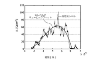
図6は、例となる状況の間に測定された、昼光の日常の変化(縦軸;Cd/m2)を時間(横軸;秒)の関数として示すグラフである。雲の通過によりもたらされ得る変動はさておき、一般的な動きが、実線で示されるように存在し、これは、キュービックフィット(cubic fit)であることが明らかに見られる。 FIG. 6 is a graph showing daily changes in daylight (vertical axis; Cd / m 2 ) as a function of time (horizontal axis; seconds), measured during an exemplary situation. Apart from the fluctuations that can be caused by the passage of clouds, there is a general movement as shown by the solid line, which is clearly seen as a cubic fit.
本発明の更なる詳細によれば、このフィットは、センサとコントローラとの間の伝送の必要性を更に最小にするために、昼光を予測し、及びそれ故に、変化率Rを適合させるために用いられ得る。 According to further details of the invention, this fit is for predicting daylight and thus adapting the rate of change R in order to further minimize the need for transmission between the sensor and the controller. Can be used.
問題は、複数の光源をもつ部屋において生じ得る。図7は、壁3と、1つの壁内の1又はそれ以上の窓4と、典型的には窓と反対側の壁に配置され、廊下(図示省略)へのアクセスを与えるドア6とをもつ部屋1の概略的な上面図である。部屋は、1つの光センサ16と、複数のランプ61,71のために共通の1つのコントローラ12とをもつ。ランプは、複数の列、即ち、窓4の近くに配置されたランプ61の第1の列、及び、窓から大きく離れて設けられたランプ71の第2の列を成して設けられる。
Problems can arise in rooms with multiple light sources. FIG. 7 shows a
斯様な状況において、窓4に近い日光のレベルLZが窓からより離れたところよりも高くなることが問題である。全てのランプが同一の出力で駆動される場合には、窓の近くの位置での光レベルが高すぎるか、若しくは、窓の反対側の位置での光レベルが低すぎるか、又は、これら双方である。
In such a situation, the problem is that the sunlight level L Z close to the
図8は、この問題を解決するために本発明により提案されたランプ制御スキームを示すグラフである。横軸は、例えばセンサ16により検出されるような日光の量LZを表し、縦軸は、窓に近いランプ61(線86)、及び、窓から離れているランプ71(線87)のための、コントローラ12により設定される、ランプのターゲット調光ファクタyTを表す。日光の量LZに基づいて、コントローラは、本図においてローマ数字で示された、5つの異なるモードで動作し得る。
FIG. 8 is a graph showing a lamp control scheme proposed by the present invention to solve this problem. The horizontal axis represents the amount of sunlight L Z as detected by the
Iで示された第1のモードにおいて、日光レベルLZは、全てのランプがフルパワー(調光レベル100%)で駆動されるほど低い特定の第1の値L1よりも低い。
In the first mode indicated by I, the daylight level L Z is lower than the specific first value L1, which is so low that all lamps are driven at full power (dimming
日光レベルLZがこの第1の値L1よりも高いが、或る第2の値L2よりも低いときには、ランプ光は、光レベルを一定に維持するために、日光レベルが増大する場合に、及び逆もまた同様に、調光され得る。それ故、コントローラは、
![]()
![]()
コントローラは、第1の予め決められたレベルAよりも高いy(61)(第2のモードII)と、この予め決められたレベルよりも低いy(61)(第3のモードIII)とを区別する。図8の例において、この第1の予め決められたレベルAは80%に等しいが、この第1の予め決められたレベルは、異なって選択され得る。前記第1の予め決められたレベルは、100%の高さであり得る。第1の予め決められたレベルAは、日光レベルLZの第3の値L3に対応することに留意されたい。 The controller obtains y (61) (second mode II) higher than the first predetermined level A and y (61) (third mode III) lower than the predetermined level. Distinguish. In the example of FIG. 8, this first predetermined level A is equal to 80%, but this first predetermined level may be selected differently. The first predetermined level may be 100% high. The first predetermined level A, it should be noted that corresponding to the third value L3 daylight level L Z.
第2のモードにおいて、離れているランプ71の調光ファクタy(71)は、
![]()
![]()
第3のモードにおいて、コントローラは、調光ファクタy(61)よりも高い、離れているランプ71の調光ファクタy(71)を選択することにより、離れているランプ71が日光LZから少ししか恩恵を受けないことを考慮に入れる。この差分y(71)−y(61)は、差分y(71)−y(61)がLZ=L3に対してゼロに等しく、LZ=L2に対して第2の予め決められたレベルBに等しくなるように、増大する日光レベルLZとともに増大する。図8の例において、この第2の予め決められたレベルBは80%に等しいが、この第2の予め決められたレベルBは異なって選択され得る。それ故、第3のモードにおいて、調光ファクタy(71)は、以下の式、
![]()
![]()
日光レベルLZが第2の値L2よりも高いときには、コントローラは、第4のモードIVにおいて、y(61)をゼロに維持する(窓に近いランプ61がオフにされる)が、y(71)が、以下の式、
![]()
![]()
好ましくは、第4のモードIVにおけるy(71)の比例ファクタは、以下の式、
![]()
![]()
日光レベルLZが第4の値L4よりも高いときには、コントローラは、第5のモードVにおいて、y(71)をゼロに維持する(離れているランプがオフにされる)。 When sunlight level L Z is greater than the fourth value L4, the controller, in the fifth mode V, maintaining y (71) to zero (apart lamp is turned off).
バリエーションにおいて、コントローラは、第5のモードVにおいて、日光レベルLZが変化するときにオン/オフの切り替えを避けるために、y(71)を小さな値、例えば1%に維持してもよい。この場合において、コントローラは、予め決められた遅延よりも長い間、例えば15分の間、LZがL4よりも高いときには、離れているランプ71の切り替え(y(71)=0)を行う。同様のバリエーションがy(61)に当てはまる。 In a variation, the controller, in the fifth mode V, and avoid switching on / off when the sunlight level L Z changes may maintain y (71) a small value, for example 1%. In this case, the controller is longer than a predetermined delay, for example, between 15 minutes, when L Z is greater than L4 switches the apart lamp 71 (y (71) = 0 ). A similar variation applies to y (61).
要約すると、本発明は、光源11と、前記光源の出力を制御するコントローラ12と、前記コントローラと無線で通信する光センサ16とを有する、照明システム10を提供する。
In summary, the present invention provides a
通常モードでは、コントローラは、光レベルが実質的に一定のままになるように光源を制御する。変化モードでは、コントローラは、光レベルが、ターゲットレベルLTからのずれを減少させるように予め決められた変化率Rで徐々に変化されるように、光源を制御する。コントローラは、光センサから受信した入力信号に基づいて、通常モードから変化モードに切り替わる。光センサは、光レベルを測定し、信号をコントローラに伝送するか否かを決定する。 In the normal mode, the controller controls the light source so that the light level remains substantially constant. In the change mode, the controller controls the light source so that the light level is gradually changed at a predetermined change rate R so as to reduce the deviation from the target level LT. The controller switches from the normal mode to the change mode based on the input signal received from the optical sensor. The light sensor measures the light level and determines whether to transmit a signal to the controller.
信号の受信が、コントローラが制御動作を変るものではないときには、光センサは、信号を送信するのを避ける。 When receiving a signal does not change the control action of the controller, the light sensor avoids transmitting a signal.
本発明は、図面及び前述の説明において詳細に示され述べられた一方で、斯様な図示及び説明は、例示又は単なる例であり、限定的なものではないと見なされるべきであることが当業者にとって明らかである。本発明は、開示された実施形態に限定されるものではなく、むしろ、幾つかのバリエーション及び変更が、特許請求の範囲に規定された本発明の保護範囲内で可能である。 While the invention has been illustrated and described in detail in the drawings and foregoing description, such illustration and description are to be considered illustrative or exemplary and not restrictive. It is clear to the contractor. The invention is not limited to the disclosed embodiments, but rather several variations and modifications are possible within the protection scope of the invention as defined in the claims.
例えば、センサ12が、光レベルの値を伝送しないが、光レベルが上側レベルLUよりも高いという事実を簡単に伝送することが可能である。コントローラは、(メモリ17に格納された)LUの値を知るので、コントローラは、実際の光レベルの非常に良好な近似値を知る。
For example, it is possible to simply transmit the fact that the
更に、窓の近くに配置されたランプ61と窓からより離れて配置されたランプ71とをもつ部屋に代えて、部屋が、日光よりむしろ異なるタイプの外側光源から外側光を受けてもよい。
Further, instead of a room having a
開示された実施形態に対する他のバリエーションは、図面、開示及び特許請求の範囲の研究から、当業者により理解され、もたらされ得る。請求項において、"有する"という用語は、他の要素又はステップを除外するものではなく、単数表記は、複数の存在を除外するものではない。単一のプロセッサ又は他のユニットが、請求項に開示された幾つかのアイテムの機能を充足してもよい。特定の手段が相互に異なる従属請求項に記載されるという単なる事実は、これらの手段の組み合わせが有利に用いられ得ないことを示すものではない。コンピュータプログラムは、他のハードウェアと一緒に又はその部分として供給された光学格納媒体又は半導体媒体のような、適切な媒体に格納/分配され得るが、インターネット又は他の有線若しくは無線の通信システムを介するような、他の形式で分配されてもよい。請求項における如何なる参照符号も、範囲を限定するものとして考慮されるべきではない。 Other variations to the disclosed embodiments can be understood and brought by those skilled in the art from a study of the drawings, the disclosure, and the claims. In the claims, the term “comprising” does not exclude other elements or steps, and the singular does not exclude a plurality. A single processor or other unit may fulfill the functions of several items disclosed in the claims. The mere fact that certain measures are recited in mutually different dependent claims does not indicate that a combination of these measured cannot be used to advantage. The computer program may be stored / distributed on a suitable medium, such as an optical storage medium or a semiconductor medium supplied with or as part of other hardware, but may be connected to the Internet or other wired or wireless communication system. It may be distributed in other forms as well. Any reference signs in the claims should not be construed as limiting the scope.
前記のものにおいて、本発明は、本発明のデバイスの機能ブロックを示すブロック図を参照して説明された。これらの機能ブロックの1又はそれ以上は、斯様な機能ブロックの機能が個別のハードウェア部品で実行されるハードウェアにおいて実行されてもよいが、斯様な機能ブロックの機能が、マイクロプロセッサ、マイクロコントローラ、デジタル信号プロセッサ等のようなプログラム可能なデバイス又はコンピュータプログラムの1又はそれ以上のプログラムラインにより実行されるように、これらの機能ブロックのうち1又はそれ以上がソフトウェアにおいて実行されることも可能であることが理解されるべきである。 In the foregoing, the present invention has been described with reference to block diagrams, which illustrate functional blocks of the device of the present invention. One or more of these functional blocks may be performed in hardware where the functions of such functional blocks are performed by separate hardware components, but the functions of such functional blocks may be implemented in a microprocessor, One or more of these functional blocks may also be executed in software, as executed by one or more program lines of a programmable device or computer program such as a microcontroller, digital signal processor, etc. It should be understood that this is possible.
Claims (12)
前記少なくとも1つの光源の出力を制御するコントローラと、
実際の光レベルを間欠的に測定し、その測定された光レベルを測定データとして前記コントローラに無線で送信可能な光センサとを有し、
前記コントローラは、光レベルが実質的に一定のままになるように前記少なくとも1つの光源を制御する通常モードと、光レベルが予め決められた範囲内になるまで予め決められた変化率で徐々に変えられるように前記少なくとも1つの光源を制御する変化モードとで動作可能であり、
前記コントローラは、前記光センサから受信した測定データに基づいて前記通常モードから前記変化モードに切り替えるように構成され、前記変化モードにおいて光レベルが予め決められた範囲内になったときに前記通常モードに戻されるように構成され、
前記光センサは、前記予め決められた範囲よりも高い予め決められた上側境界を規定するとともに前記予め決められた範囲よりも低い予め決められた下側境界を規定する情報をもち、前記光センサは、前記測定された光レベルが前記上側境界と前記下側境界との間にある場合に前記測定データの送信をやめるように構成され、
前記光センサは、前記コントローラが前記変化モードで動作しているときには、前記測定された光レベルが前記上側境界と前記下側境界との間にない場合であっても、前記測定データの送信をやめるように構成される、照明システム。 At least one light source;
A controller for controlling the output of the at least one light source;
Actual light level intermittently measured, and an optical sensor can be transmitted wirelessly to the controller the measured light level as measurement data,
The controller includes a normal mode for controlling the at least one light source so that the light level remains substantially constant and gradually at a predetermined rate of change until the light level is within a predetermined range. Operable in a change mode that controls the at least one light source to be changed ;
The controller is the normal mode when said configured from the normal mode based on the measurement data received from the light sensor to switch to the change mode, it falls within a range in which the light level is predetermined in the change mode Configured to return to
The optical sensor has information defining a predetermined upper boundary lower than the predetermined range and defining a predetermined upper boundary higher than the predetermined range, and the optical sensor Is configured to stop transmitting the measurement data when the measured light level is between the upper boundary and the lower boundary;
The optical sensor transmits the measurement data when the controller is operating in the change mode, even when the measured light level is not between the upper boundary and the lower boundary. A lighting system configured to quit .
前記光センサは、第1のモードにおいて、測定された光レベルが前記上側境界と前記下側境界との間にある場合に送信を避ける、請求項1に記載のシステム。 The light sensor has information defining a predetermined upper boundary higher than the target level and a predetermined lower boundary lower than the target level;
The system of claim 1, wherein the light sensor avoids transmission in a first mode when a measured light level is between the upper boundary and the lower boundary.
前記コントローラは、測定信号の受信に応答して、前記光源の前記光出力を徐々に減少させるように設計され、
前記光センサは、前記信号を前記コントローラに送信した後に、第2のモードで動作し、前記第2のモードにおいて、前記光センサは、測定された光レベルが前記シフト上側境界と前記シフト下側境界との間にある場合に送信を避けるために、後の測定時点で、前記シフト上側境界及び前記シフト下側境界を徐々に減少させるように適合される、請求項3に記載のシステム。 The light sensor sends a signal to the controller if the measured light level is higher than the upper boundary, a shift target level higher than the target level, a shift upper boundary higher than the shift target level, And obtaining from the memory information defining a lower shift boundary below the shift target level;
The controller is designed to gradually reduce the light output of the light source in response to receiving a measurement signal;
The optical sensor operates in a second mode after transmitting the signal to the controller, and in the second mode, the optical sensor has a measured light level between the shift upper boundary and the shift lower side. The system of claim 3, wherein the system is adapted to gradually decrease the upper shift boundary and the lower shift boundary at a later measurement time to avoid transmission when in between.
前記光センサは、メモリ内に、前記シフトターゲットレベル、前記シフト上側境界及び前記シフト下側境界の変化率を規定するデータをもち、
前記光センサが第2のモードから第1のモードに切り替えられた後の第1の測定時点で、測定された光レベルが前記上側境界よりも高いか又は前記下側境界よりも低いことを前記光センサが理解した場合に、
a)前記光センサは、信号を前記コントローラに送信し、前記第2のモードで動作するように切り替わり、
b)前記コントローラは、メモリ内の前記変化率を適合させ、
c)前記光センサが、対応する態様でメモリ内の前記変化率を適合させる、請求項5に記載のシステム。 The controller has a memory including a rate of change of the light output of the light source,
The optical sensor has data defining a shift target level, a shift upper boundary and a shift lower boundary change rate in a memory;
The measured light level is higher than the upper boundary or lower than the lower boundary at a first measurement time after the light sensor is switched from the second mode to the first mode. If the light sensor understands,
a) the light sensor sends a signal to the controller and switches to operate in the second mode;
b) the controller adapts the rate of change in memory;
6. The system of claim 5, wherein c) the light sensor adapts the rate of change in memory in a corresponding manner.
前記外部光源からより離れて配置された1又はそれ以上のランプの第2のグループを有し、
前記コントローラは、第2の調光ファクタy(71)が常に第1の調光ファクタy(61)よりも高くなるか又は前記第1の調光ファクタy(61)と等しくなるように、ランプの前記第1のグループの前記第1の調光ファクタy(61)とランプの前記第2のグループの前記第2の調光ファクタy(71)とを日光のレベルの関数として制御し、
調光ファクタ=ゼロはランプがオフであることを示し、調光ファクタ=100%はランプが完全にオンであることを示す、請求項1〜6のうちいずれか一項に記載のシステム。 Having a first group of one or more lamps positioned relatively close to an external light source;
Having a second group of one or more lamps located farther from the external light source;
The controller includes a lamp so that the second dimming factor y (71) is always higher than or equal to the first dimming factor y (61). Controlling the first dimming factor y (61) of the first group of lamps and the second dimming factor y (71) of the second group of lamps as a function of the level of sunlight;
Dimming factor = zero indicates that the lamp is off and dimming factor = 100% indicates that the lamp is fully on.
前記日光レベルLzが前記第1の値L1と特定の第3の値L3との間にある場合には、前記コントローラは、y(61)=y(71)=100%×(L2−LZ)/(L2−L1)である第2のモードで動作し、L2は、前記第3の値L3よりも高い第2の値L2であり、
前記日光レベルLzが前記第3の値L3と前記第2の値L2との間にある場合には、前記コントローラは、y(61)=100%×(L2−LZ)/(L2−L1),y(71)=y(61)+B×(LZ−L3)/(L2−L3)である第3のモードで動作し、Bは予め決められた調光ファクタであり、
前記日光レベルLzが前記第2の値L2と第4の値L4との間にある場合には、前記コントローラは、y(61)=δ,y(71)=B×(L4−LZ)/(L4−L2)である第4のモードで動作し、
前記日光レベルが前記第4の値よりも高い場合には、前記コントローラは、y(61)=y(71)=δである第5のモードで動作する、請求項7に記載のシステム。 If the sunlight level L Z is between zero and a specific first value L1, the controller operates in the first mode y (61) = y (71) = 100%;
When the sunlight level Lz is between the first value L1 and the specific third value L3, the controller y (61) = y (71) = 100% × (L2−L Z ) / (L2−L1), and L2 is a second value L2 higher than the third value L3,
When the sunlight level Lz is between the third value L3 and the second value L2, the controller calculates y (61) = 100% × (L2−L Z ) / (L2−L1). ), Y (71) = y (61) + B × (L Z −L3) / (L2−L3), where B is a predetermined dimming factor,
When the sunlight level Lz is between the second value L2 and the fourth value L4, the controller y (61) = δ, y (71) = B × (L4−L Z ) / (L4-L2) is operated in the fourth mode,
8. The system of claim 7, wherein the controller operates in a fifth mode where y (61) = y (71) = δ when the sunlight level is higher than the fourth value.
Applications Claiming Priority (3)
| Application Number | Priority Date | Filing Date | Title |
|---|---|---|---|
| EP08160958 | 2008-07-23 | ||
| EP08160958.8 | 2008-08-23 | ||
| PCT/IB2009/053088 WO2010010491A2 (en) | 2008-07-23 | 2009-07-16 | Illumination system with automatic adaptation to daylight level |
Publications (3)
| Publication Number | Publication Date |
|---|---|
| JP2011529249A JP2011529249A (en) | 2011-12-01 |
| JP2011529249A5 JP2011529249A5 (en) | 2014-01-23 |
| JP5539345B2 true JP5539345B2 (en) | 2014-07-02 |
Family
ID=41509743
Family Applications (1)
| Application Number | Title | Priority Date | Filing Date |
|---|---|---|---|
| JP2011519265A Active JP5539345B2 (en) | 2008-07-23 | 2009-07-16 | Lighting system that automatically adapts to daylight levels |
Country Status (6)
| Country | Link |
|---|---|
| US (2) | US8575846B2 (en) |
| EP (1) | EP2319277A2 (en) |
| JP (1) | JP5539345B2 (en) |
| CN (1) | CN102106189B (en) |
| TW (1) | TW201013350A (en) |
| WO (1) | WO2010010491A2 (en) |
Families Citing this family (41)
| Publication number | Priority date | Publication date | Assignee | Title |
|---|---|---|---|---|
| US8760293B2 (en) | 2009-03-27 | 2014-06-24 | Lutron Electronics Co., Inc. | Wireless sensor having a variable transmission rate |
| US8451116B2 (en) * | 2009-03-27 | 2013-05-28 | Lutron Electronics Co., Inc. | Wireless battery-powered daylight sensor |
| EP2438798B1 (en) * | 2009-06-04 | 2018-09-26 | Philips Lighting Holding B.V. | Wake-up of light sensor in a lighting system |
| GB201007727D0 (en) * | 2010-05-10 | 2010-06-23 | Foti Ivan | Lighting devices |
| US20150061503A1 (en) * | 2010-08-03 | 2015-03-05 | Enlighted, Inc. | Intelligent light emitting diode (led) controller and driver |
| CN102564577B (en) * | 2010-12-16 | 2016-01-06 | 财团法人资讯工业策进会 | Illuminance sensing system and method |
| JP6067674B2 (en) * | 2011-04-04 | 2017-01-25 | フィリップス ライティング ホールディング ビー ヴィ | Device and method for illumination control of multiple light sources |
| EP2721905B1 (en) * | 2011-06-16 | 2019-09-11 | Signify Holding B.V. | Robust daylight integration with the aid of coded light. |
| DE102011081097A1 (en) * | 2011-08-17 | 2013-02-21 | Siemens Aktiengesellschaft | Method for controlling and regulating a lighting system |
| WO2013068866A1 (en) * | 2011-11-10 | 2013-05-16 | Koninklijke Philips Electronics N.V. | Presence detection using split beam luminaire |
| US8842009B2 (en) | 2012-06-07 | 2014-09-23 | Mojo Labs, Inc. | Multiple light sensor multiple light fixture control |
| US8749146B2 (en) | 2011-12-05 | 2014-06-10 | Mojo Labs, Inc. | Auto commissioning of light fixture using optical bursts |
| ITVE20120014A1 (en) * | 2012-04-13 | 2013-10-14 | Teleco Automation Srl | BRIGHTNESS CONTROL DEVICE IN AN ENVIRONMENT.- |
| DE102013104136B4 (en) | 2012-05-18 | 2023-11-16 | Insta Gmbh | Method for constant light control and device for lighting a room |
| CN102736531B (en) * | 2012-06-14 | 2014-06-25 | 华北电力大学 | Distributed self-learning sequential control system and method based on wireless network |
| CN102788968B (en) * | 2012-07-18 | 2014-12-10 | 无锡清华信息科学与技术国家实验室物联网技术中心 | Indoor passive tracking method and system based on wireless light sensor network |
| EP2909590A1 (en) | 2012-10-16 | 2015-08-26 | Koninklijke Philips N.V. | Illumination sensor for distinguishing between different contributions to a sensed light level |
| EP2770804B1 (en) | 2013-02-26 | 2020-07-15 | Nxp B.V. | Lighting control method, computer program product and lighting control system |
| US9804024B2 (en) | 2013-03-14 | 2017-10-31 | Mojo Labs, Inc. | Light measurement and/or control translation for daylighting |
| US10161612B2 (en) | 2013-03-15 | 2018-12-25 | Cree, Inc. | Ambient light monitoring in a lighting fixture |
| EP2804443B1 (en) * | 2013-05-14 | 2017-06-28 | Herbert Waldmann GmbH & Co. KG | Method for operating a light |
| JP6259636B2 (en) * | 2013-10-18 | 2018-01-10 | 三菱電機株式会社 | Lighting control apparatus and lighting control system |
| JP6173164B2 (en) * | 2013-10-18 | 2017-08-02 | 三菱電機株式会社 | Lighting control device |
| US10470267B2 (en) * | 2013-11-22 | 2019-11-05 | Ideal Industries Lighting Llc | Ambient light regulation methods |
| JP6416915B2 (en) * | 2014-01-08 | 2018-10-31 | フィリップス ライティング ホールディング ビー ヴィ | Method and apparatus for controlling illumination based on detected illumination changes |
| US9538614B2 (en) * | 2014-12-31 | 2017-01-03 | Echelon Corporation | Apparatuses and methods to detect and provision for lighting interfaces |
| US10070496B2 (en) | 2015-03-30 | 2018-09-04 | Mojo Labs, Inc. | Task to wall color control |
| US9456482B1 (en) | 2015-04-08 | 2016-09-27 | Cree, Inc. | Daylighting for different groups of lighting fixtures |
| US9750103B2 (en) | 2015-05-01 | 2017-08-29 | 3M Innovative Properties Company | Apparatus and method for ambient light measurement by a solid state light bulb |
| US10408922B2 (en) | 2015-07-10 | 2019-09-10 | Ams Sensors Singapore Pte. Ltd. | Optoelectronic module with low- and high-power illumination modes |
| WO2017076680A1 (en) * | 2015-11-04 | 2017-05-11 | Philips Lighting Holding B.V. | Intelligent gating mechanism |
| US10082283B2 (en) | 2016-03-24 | 2018-09-25 | 3M Innovative Properties Company | Apparatus and method for ambient light measurement by a solid state light bulb |
| US10027410B2 (en) | 2016-06-23 | 2018-07-17 | Abl Ip Holding Llc | System and method using a gated retro-reflector for visible light uplink communication |
| DE102016218625A1 (en) * | 2016-09-27 | 2017-09-07 | Siemens Schweiz Ag | Method and arrangement for brightness control, in particular constant light control |
| US10145525B2 (en) | 2016-10-19 | 2018-12-04 | Abl Ip Holding Llc | Photo-voltaic powered wireless sensor for passive optical lighting |
| US20190297700A1 (en) * | 2016-12-20 | 2019-09-26 | Taolight Company Limited | Device, system and method for controlling operation of lighting units |
| US10419953B2 (en) * | 2017-12-05 | 2019-09-17 | Echelon Corporation | Self-healing lighting network |
| KR102588692B1 (en) | 2018-04-05 | 2023-10-12 | 한국전자통신연구원 | Method and apparatus for automatically controlling illumination based on illuminance contribution |
| CN109195284B (en) * | 2018-09-21 | 2020-07-31 | 赛尔富电子有限公司 | Illumination control method and system |
| US11350507B2 (en) | 2019-10-21 | 2022-05-31 | Milwaukee Electric Tool Corporation | Portable lighting device with ramp-down capability |
| KR102446542B1 (en) * | 2022-03-08 | 2022-09-23 | 주식회사 온유테크 | Led illumination apparatus and operating method thereof |
Family Cites Families (17)
| Publication number | Priority date | Publication date | Assignee | Title |
|---|---|---|---|---|
| JPH05152077A (en) * | 1991-11-29 | 1993-06-18 | Kyocera Corp | Automatic dimming system |
| US5455487A (en) | 1993-09-22 | 1995-10-03 | The Watt Stopper | Moveable desktop light controller |
| DE19514972A1 (en) * | 1995-04-24 | 1996-10-31 | Steinel Gmbh & Co Kg | Twilight switch |
| JPH09289086A (en) * | 1996-04-23 | 1997-11-04 | Matsushita Electric Works Ltd | Daylight sensor for remote control |
| JPH11162655A (en) * | 1997-11-25 | 1999-06-18 | Matsushita Electric Works Ltd | Illumination system |
| US6340864B1 (en) | 1999-08-10 | 2002-01-22 | Philips Electronics North America Corporation | Lighting control system including a wireless remote sensor |
| US6891284B2 (en) | 2003-04-18 | 2005-05-10 | David A Tilley | Electronic timer with photosensor |
| JP4367090B2 (en) | 2003-10-31 | 2009-11-18 | 日本電気株式会社 | Observation result communication terminal and information collection system |
| US7274907B1 (en) | 2003-12-19 | 2007-09-25 | Unites States Of America As Represented By The Administrator Of The National Aeronautics And Space Administration | Wireless instrumentation system and power management scheme therefore |
| JP4374472B2 (en) * | 2003-12-22 | 2009-12-02 | 学校法人同志社 | Lighting control system |
| US7619539B2 (en) * | 2004-02-13 | 2009-11-17 | Lutron Electronics Co., Inc. | Multiple-input electronic ballast with processor |
| DE102004018912A1 (en) | 2004-04-15 | 2005-11-03 | Patent-Treuhand-Gesellschaft für elektrische Glühlampen mbH | Device for light control |
| GB0411156D0 (en) * | 2004-05-19 | 2004-06-23 | Powtier Controls Ltd | Wireless sensors |
| US7119678B2 (en) * | 2004-05-26 | 2006-10-10 | Honeywell International, Inc. | Wireless light sensor input to a security system |
| WO2008000086A1 (en) | 2006-06-30 | 2008-01-03 | Fibro Light Technology Inc. | Integrated sensor and light level adjustment apparatus for 'daylight harvesting' |
| CN101175350A (en) * | 2006-10-31 | 2008-05-07 | 宁波安迪光电科技有限公司 | Energy-saving illumination device |
| US8760293B2 (en) * | 2009-03-27 | 2014-06-24 | Lutron Electronics Co., Inc. | Wireless sensor having a variable transmission rate |
-
2009
- 2009-07-16 JP JP2011519265A patent/JP5539345B2/en active Active
- 2009-07-16 EP EP09786618A patent/EP2319277A2/en not_active Withdrawn
- 2009-07-16 US US13/054,657 patent/US8575846B2/en active Active
- 2009-07-16 WO PCT/IB2009/053088 patent/WO2010010491A2/en active Application Filing
- 2009-07-16 CN CN200980128603.7A patent/CN102106189B/en active Active
- 2009-07-21 TW TW098124593A patent/TW201013350A/en unknown
-
2013
- 2013-10-08 US US14/048,187 patent/US9179522B2/en active Active
Also Published As
| Publication number | Publication date |
|---|---|
| US9179522B2 (en) | 2015-11-03 |
| CN102106189B (en) | 2014-08-13 |
| CN102106189A (en) | 2011-06-22 |
| WO2010010491A2 (en) | 2010-01-28 |
| WO2010010491A3 (en) | 2010-06-10 |
| US8575846B2 (en) | 2013-11-05 |
| US20110115386A1 (en) | 2011-05-19 |
| TW201013350A (en) | 2010-04-01 |
| JP2011529249A (en) | 2011-12-01 |
| US20140035468A1 (en) | 2014-02-06 |
| EP2319277A2 (en) | 2011-05-11 |
| US20150245444A9 (en) | 2015-08-27 |
Similar Documents
| Publication | Publication Date | Title |
|---|---|---|
| JP5539345B2 (en) | Lighting system that automatically adapts to daylight levels | |
| US9554446B2 (en) | Calibration operation of a lighting device | |
| JP6157119B2 (en) | Wake-up of light sensor in lighting equipment | |
| JP5075673B2 (en) | Lighting control system | |
| EP2362715B1 (en) | Integration of computing device and lighting system | |
| US9967952B2 (en) | Demand response for networked distributed lighting systems | |
| EP2080420A2 (en) | Method of load shedding to reduce the total power consumption of a load control system | |
| US9474126B2 (en) | Operating device for light-emitting means for determining an energy or power consumption and method for detecting same | |
| CA3169132A1 (en) | Configuration for a load regulation device for lighting control | |
| US20170374722A1 (en) | Lighting Fixture Controlling Device, Light Controlling System and Method for Controlling Energy Consumption | |
| KR20160119385A (en) | System for driving control of LED | |
| JP2003347068A (en) | Lighting control device | |
| JP2004228051A (en) | Lighting control device and lighting system | |
| WO2017222825A1 (en) | System and method for automated light level and daylight harvesting calibration using mobile handheld devices | |
| JP4915662B2 (en) | Lighting system | |
| EP2911481B1 (en) | Method and device for calibrating a dimmer controller | |
| JP4340164B2 (en) | Lighting control system | |
| JP3674803B2 (en) | Lighting control system | |
| TW201431441A (en) | Lamp device group control system and method |
Legal Events
| Date | Code | Title | Description |
|---|---|---|---|
| A521 | Request for written amendment filed |
Free format text: JAPANESE INTERMEDIATE CODE: A523 Effective date: 20120712 |
|
| A621 | Written request for application examination |
Free format text: JAPANESE INTERMEDIATE CODE: A621 Effective date: 20120712 |
|
| A977 | Report on retrieval |
Free format text: JAPANESE INTERMEDIATE CODE: A971007 Effective date: 20130829 |
|
| A131 | Notification of reasons for refusal |
Free format text: JAPANESE INTERMEDIATE CODE: A131 Effective date: 20130903 |
|
| A524 | Written submission of copy of amendment under article 19 pct |
Free format text: JAPANESE INTERMEDIATE CODE: A524 Effective date: 20131128 |
|
| TRDD | Decision of grant or rejection written | ||
| A01 | Written decision to grant a patent or to grant a registration (utility model) |
Free format text: JAPANESE INTERMEDIATE CODE: A01 Effective date: 20140401 |
|
| R150 | Certificate of patent or registration of utility model |
Ref document number: 5539345 Country of ref document: JP Free format text: JAPANESE INTERMEDIATE CODE: R150 |
|
| A61 | First payment of annual fees (during grant procedure) |
Free format text: JAPANESE INTERMEDIATE CODE: A61 Effective date: 20140430 |
|
| S111 | Request for change of ownership or part of ownership |
Free format text: JAPANESE INTERMEDIATE CODE: R313113 |
|
| R350 | Written notification of registration of transfer |
Free format text: JAPANESE INTERMEDIATE CODE: R350 |
|
| R250 | Receipt of annual fees |
Free format text: JAPANESE INTERMEDIATE CODE: R250 |
|
| R250 | Receipt of annual fees |
Free format text: JAPANESE INTERMEDIATE CODE: R250 |
|
| R250 | Receipt of annual fees |
Free format text: JAPANESE INTERMEDIATE CODE: R250 |
|
| S531 | Written request for registration of change of domicile |
Free format text: JAPANESE INTERMEDIATE CODE: R313531 |
|
| S533 | Written request for registration of change of name |
Free format text: JAPANESE INTERMEDIATE CODE: R313533 |
|
| R350 | Written notification of registration of transfer |
Free format text: JAPANESE INTERMEDIATE CODE: R350 |
|
| R250 | Receipt of annual fees |
Free format text: JAPANESE INTERMEDIATE CODE: R250 |
|
| R250 | Receipt of annual fees |
Free format text: JAPANESE INTERMEDIATE CODE: R250 |
|
| R250 | Receipt of annual fees |
Free format text: JAPANESE INTERMEDIATE CODE: R250 |
|
| R250 | Receipt of annual fees |
Free format text: JAPANESE INTERMEDIATE CODE: R250 |