JP5539083B2 - Shutter device, imaging device, and shutter control method - Google Patents
Shutter device, imaging device, and shutter control method Download PDFInfo
- Publication number
- JP5539083B2 JP5539083B2 JP2010164353A JP2010164353A JP5539083B2 JP 5539083 B2 JP5539083 B2 JP 5539083B2 JP 2010164353 A JP2010164353 A JP 2010164353A JP 2010164353 A JP2010164353 A JP 2010164353A JP 5539083 B2 JP5539083 B2 JP 5539083B2
- Authority
- JP
- Japan
- Prior art keywords
- opening
- blade member
- shutter
- closing
- exposure
- Prior art date
- Legal status (The legal status is an assumption and is not a legal conclusion. Google has not performed a legal analysis and makes no representation as to the accuracy of the status listed.)
- Expired - Fee Related
Links
Images


Classifications
-
- G—PHYSICS
- G03—PHOTOGRAPHY; CINEMATOGRAPHY; ANALOGOUS TECHNIQUES USING WAVES OTHER THAN OPTICAL WAVES; ELECTROGRAPHY; HOLOGRAPHY
- G03B—APPARATUS OR ARRANGEMENTS FOR TAKING PHOTOGRAPHS OR FOR PROJECTING OR VIEWING THEM; APPARATUS OR ARRANGEMENTS EMPLOYING ANALOGOUS TECHNIQUES USING WAVES OTHER THAN OPTICAL WAVES; ACCESSORIES THEREFOR
- G03B9/00—Exposure-making shutters; Diaphragms
- G03B9/08—Shutters
- G03B9/10—Blade or disc rotating or pivoting about axis normal to its plane
- G03B9/14—Two separate members moving in opposite directions
-
- G—PHYSICS
- G03—PHOTOGRAPHY; CINEMATOGRAPHY; ANALOGOUS TECHNIQUES USING WAVES OTHER THAN OPTICAL WAVES; ELECTROGRAPHY; HOLOGRAPHY
- G03B—APPARATUS OR ARRANGEMENTS FOR TAKING PHOTOGRAPHS OR FOR PROJECTING OR VIEWING THEM; APPARATUS OR ARRANGEMENTS EMPLOYING ANALOGOUS TECHNIQUES USING WAVES OTHER THAN OPTICAL WAVES; ACCESSORIES THEREFOR
- G03B9/00—Exposure-making shutters; Diaphragms
- G03B9/08—Shutters
- G03B9/10—Blade or disc rotating or pivoting about axis normal to its plane
- G03B9/24—Adjusting size of aperture formed by members when fully open so as to constitute a virtual diaphragm that is adjustable
Description
本発明は、絞り機能付きシャッター装置、及び該シャッター装置を搭載した撮像装置に関する。 The present invention relates to a shutter device with an aperture function, and an imaging device equipped with the shutter device.
従来の銀塩カメラに搭載されていた絞り機能付きシャッター装置では幕速(羽根部材の駆動速度)に応じたF値まで羽根部材を開き、すぐに羽根部材を閉じるという動作でシャッターを切っていた。羽根部材が開き始めたら露光開始となり、所定の絞り値となった時点で羽根部材の駆動方向を開く方向から閉じる方向に反転させる(図8(b)参照)。 In a shutter device with a diaphragm function mounted on a conventional silver salt camera, the shutter is opened by opening the blade member up to the F value corresponding to the curtain speed (drive speed of the blade member) and then immediately closing the blade member. . When the blade member begins to open, exposure starts, and when the predetermined aperture value is reached, the driving direction of the blade member is reversed from the opening direction to the closing direction (see FIG. 8B).
一方、電子カメラなどの撮像装置では、撮像素子が露光された状態で撮像素子に蓄積されている電荷をリセット(リセット走査)して電荷の蓄積を開始させることで、羽根部材を往復動作させずに開いた状態から閉じ方向に動作させるだけで撮影が可能である。 On the other hand, in an imaging device such as an electronic camera, the charge accumulated in the image sensor is reset (reset scan) in the exposed state of the image sensor, and charge accumulation is started, so that the blade member does not reciprocate. It is possible to take a picture only by moving it from the open state to the closing direction.
しかしながら、羽根部材の閉動作を指示してから実際に閉動作が開始されるまでの遅延時間が長い場合、羽根部材への閉動作の指示を基準にしてリセット走査を行う構成だとシャッタースピードの高速化が困難である。 However, if the delay time from when the blade member closing operation is instructed to when the closing operation is actually started is long, reset scanning is performed based on the closing operation instruction to the blade member. Speeding up is difficult.
特許文献1には、電子カメラのシャッター装置におけるシャッター羽根の閉動作をセンサで検出し、閉動作の検出時点を起点として、測光データに基づく露光時間に対応させて露光開始タイミングを設定する技術が記載されている(図8(a)参照)。引用文献1に記載された技術を用いると、羽根部材の閉動作を指示してから実際に閉動作が開始されるまでの遅延時間が長い場合であってもシャッタースピードの高速化が可能である。
Japanese Patent Application Laid-Open No. 2004-133867 discloses a technique for detecting a closing operation of a shutter blade in a shutter device of an electronic camera with a sensor, and setting an exposure start timing corresponding to an exposure time based on photometric data, starting from the detection time of the closing operation. (See FIG. 8 (a)). When the technique described in the cited
しかしながら、上記特許文献1に記載の技術では、シャッター機構やシャッター駆動機構とは別にシャッター羽根の閉動作を検出するセンサが必要となる。
However, the technique described in
本発明は、上記課題に鑑みてなされ、羽根部材の閉動作を検出するセンサを用いることなく、シャッタースピードを高速化できるようにすることを目的とする。 The present invention has been made in view of the above problems, and an object thereof is to increase the shutter speed without using a sensor for detecting the closing operation of the blade member.
上記課題を解決し、目的を達成するために、本発明は、撮像装置に搭載される絞り機能付きシャッター装置であって、被写体からの光が通過する開口部を開閉すると共に、当該開口部の開口面積を調整する羽根部材と、前記羽根部材を絞りとして開閉駆動するための第1の駆動制御と、シャッターとして開閉駆動するための第2の駆動制御とが可能な駆動手段と、前記駆動手段と撮像素子とを制御する制御手段と、を備え、前記制御手段は、被写体を撮像素子により撮像するときに適正な露出となるように、前記羽根部材を絞りとして閉じ方向に駆動した第1の位置から、一旦羽根部材を開く方向に駆動した後、前記羽根部材を全閉位置まで作動させる途中で前記撮像素子への露光を開始する。 In order to solve the above-described problems and achieve the object, the present invention is a shutter device with an aperture function mounted on an imaging device, which opens and closes an opening through which light from a subject passes and A blade member that adjusts an opening area; a drive unit capable of performing a first drive control for opening and closing the blade member as a diaphragm; and a second drive control for opening and closing the shutter member as a shutter; and the drive unit And a control means for controlling the image sensor, wherein the control means is driven in the closing direction by using the blade member as a diaphragm so that a proper exposure is obtained when the subject is imaged by the image sensor. After driving from the position in the direction in which the blade member is opened, exposure to the image sensor is started in the middle of operating the blade member to the fully closed position.
また前記制御手段は、シャッター駆動開始タイミングからシャッター全閉状態までの遅延時間を考慮した第1のシャッタータイミング制御と、シャッター羽根が閉動作途中の撮像素子の露光開始からシャッター全閉状態までの遅延時間を考慮した第2のシャッタータイミング制御とを備え、露光時間とシャッター装置の幕速時間との比較結果に応じて前記シャッター制御手段を使い分けることで、前記羽根部材を開いた位置から全閉位置へ作動開始するタイミングと、撮像素子への露光を開始するタイミングを決定する。 Further, the control means includes a first shutter timing control considering a delay time from the shutter driving start timing to the shutter fully closed state, and a delay from the start of exposure of the image sensor while the shutter blade is in the closing operation to the shutter fully closed state. Second shutter timing control that takes time into account, and by selectively using the shutter control means in accordance with the comparison result between the exposure time and the curtain speed of the shutter device, the blade member is opened to the fully closed position. The timing to start the operation and the timing to start exposure to the image sensor are determined.
本発明によれば、羽根部材の閉動作を検出するセンサを用いることなく、シャッタースピードを高速化できる。 According to the present invention, the shutter speed can be increased without using a sensor for detecting the closing operation of the blade member.
以下に、添付図面を参照して本発明を実施するための形態について詳細に説明する。尚、以下に説明する実施の形態は、本発明の実現手段としての一例であり、本発明が適用される装置の構成や各種条件によって適宜修正又は変更されるべきものであり、本発明は以下の実施の形態に限定されるものではない。 EMBODIMENT OF THE INVENTION Below, the form for implementing this invention with reference to an accompanying drawing is demonstrated in detail. The embodiment described below is an example as means for realizing the present invention, and should be appropriately modified or changed according to the configuration and various conditions of the apparatus to which the present invention is applied. It is not limited to the embodiment.
[装置構成]先ず、図1乃至図3を参照して、本実施の形態における撮像装置に搭載される絞り機能付きシャッター装置(以下、絞り兼用シャッターとも称す)の構成について説明する。 [Apparatus Configuration] First, the configuration of a shutter device with an aperture function (hereinafter also referred to as aperture / shutter) mounted in the imaging apparatus according to the present embodiment will be described with reference to FIGS.
本実施の形態の絞り兼用シャッターは、被写体の光束が入射する開口領域の面積(開口面積)を調整する羽根部材4,5を備える。これらの羽根部材4,5の開閉動作は、入射光量を調節する絞りとして開閉駆動するための第1の駆動制御と、露光時間を調節するシャッターとして開閉駆動するための第2の駆動制御とが可能である。
The diaphragm shutter according to the present embodiment includes
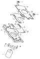
図中、1はステッピングモータ、2は地板、3はアームである。アーム3はステッピングモータ1の駆動軸1aに取り付けられて、ステッピングモータ1の回転動作に従い揺動する。地板2の一方面にはステッピングモータ1が固定され、他方面には2枚の羽根部材4,5が担持されている。地板2の他方面から突設されたガイド軸2aに羽根部材4,5に形成された長孔4b,5bを係合させてガイドすることにより、羽根部材4,5が長孔4b,5bに沿って互いに近接する方向又は離間する方向に直線的に移動する。
In the figure, 1 is a stepping motor, 2 is a ground plane, and 3 is an arm. The
6は地板2の他方面にビス7により取り付けられるカバー部材であり、地板2との間に羽根部材4,5を収容して閉塞する。カバー部材6には絞りの開放径(最大開口径)を決める開口部6aが形成されている。アーム3の両端部に突設された軸3a,3bは、地板2に形成された円弧孔を介してそれぞれ2枚の羽根部材4,5に形成された孔4a,5aに嵌装されている。アーム3がステッピングモータ1の駆動軸1aの回転により揺動すると、軸3a,3bが孔4a,5aを押す又は引くことにより2枚の羽根部材4,5がそれぞれ同一直線上で互いに相反する方向にスライドする。このことにより、カバー部材6の開口部6aで規定される最大開口径が羽根部材4,5の曲線部4c,5cが重なることで形成される絞りの形状により遮蔽され、開口面積が大きくなったり小さくなったりする。
A
絞りの開口面積はステッピングモータ1の回動によりアーム3の回転位相を制御することによって所望の値に調整可能である(図3(b)参照)。
The aperture area of the diaphragm can be adjusted to a desired value by controlling the rotation phase of the
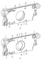
また、図2(a)及び図3(a)に示すように、アーム3が紙面に対して時計回りに回転し、軸3aが右端及び軸3bが左端(開ストッパー)にあるステップ0の位置にあるときに開口面積が最大となり開放(全開)状態になる。このようなステッピングモータ1のステップ数と開口面積との関係についての詳細は後述する。この最大の開口面積は開口部6aの面積より大きくなるように設定されており、絞りとしての開放径は開口部6aの面積で決まることになる。なお、本実施の形態では、開口部2bの面積を開口部6aより大きく設定し、開放径を開口部6aにより規定する場合を説明するが、開口部2bの面積を開口部6aより小さく設定し、開口部2bで開放径を規定してもよい。あるいは、開口部2b及び開口部6aの両者により開放径を規定するようにしてもよい。
Further, as shown in FIGS. 2A and 3A, the position of
アーム3が紙面に対して反時計方向に回転し、軸3aが左端及び軸3bが右端(閉ストッパー)にあるステップ8の位置にあるときに開口部6aが曲線部4c,5cの重なりにより完全に塞がれることで図2(b)に示すように全閉状態になる。
When the
以上述べたように、2枚の羽根部材4,5で開口面積を制御することで絞りの機能を実現し、開口部6aを全開又は全閉にすることでシャッター機能を実現している。
As described above, the aperture function is controlled by the two
次に、図4を用いてステッピングモータ1の駆動状態を説明する。図4(a)はステッピングモータ1のステップ数(STEP)、位相(PHASE)、ステータス(STATUS)、絞りのF値、開閉位置を例示している。図4(a)におけるステップは位相に記述されている1−2相駆動の際のステップで表している。なお、ステッピングモータ1をマイクロステップ駆動することにより、ステッピングモータ1の特定の1相、2相などの位相位置以外の角度にもアーム3を回転させることができる。よって、絞り開口面積は位相ごとのステップ数だけでなく、マイクロステップ駆動の分割数に応じた分解能でステップ間の途中の位置に自在に制御可能となる。マイクロステップ駆動はステッピングモータに送るパルスの1周期分の矩形波を正弦波にして、その正弦波を分割数で除したパルスに細分化したものである。
Next, the driving state of the stepping
図4(b)は撮影時のステッピングモータ1の動作を模式的に示している。図4(b)の縦軸はステッピングモータ1のステップ数を表しており絞りの開口面積の大きさに対応している。すなわち、図4(a)に示した対応関係に基づき、縦軸の上方であるほど絞りの開口面積が大きくなる。図4(b)の横軸は時間tを表している。
FIG. 4B schematically shows the operation of the stepping
図4(b)に示す開口面積を時間tで積分した値、すなわち露光が開始されてから開口部6aが閉じるまでの面積の積算値によって露光量が決定される。シャッタースピードを高速化するためには、露光開始してから羽根部材4,5により開口部6aを全閉するまでの時間が短ければよく、羽根部材4,5の閉じる速度が速ければよい。そのためには、羽根部材4,5の動き始めの曲線部分ができるだけ露光時間内に入らないようにすればよい。
The exposure amount is determined by a value obtained by integrating the opening area shown in FIG. 4B with time t, that is, an integrated value of the area from the start of exposure until the
図4(b)では、露光を開始させる際に、一旦羽根部材4,5を開動作させてから閉動作を行う制御を示している。このような制御を行うことで、羽根部材4,5の動き始めの曲線部分が露光時間に入らないようにし、高速のシャッタースピードを実現することができる。
FIG. 4B shows control in which the closing operation is performed after the
[制御フロー]以下に、図5乃至図7を参照して、本実施の形態の絞り機能付きシャッター装置を備えた撮像装置の制御構成及び撮影動作について説明する。なお、図5は、上述した絞り機能付きシャッター装置を備えた撮像装置のブロック図であり、図6は、該撮像装置の撮影動作を示すフローチャートである。また、図7は、該撮像装置の撮影時における、撮像素子及びシャッター装置の制御タイミングを示す図である。なお、以下の述べる動作は、特に記述しない限り、撮像装置のマイクロコンピュータ10が電源オン時にファームウェアのプログラムをROMからRAMへロードして実行することにより実現される。
[Control Flow] With reference to FIGS. 5 to 7, the control configuration and photographing operation of the image pickup apparatus including the shutter device with an aperture function according to the present embodiment will be described below. FIG. 5 is a block diagram of an image pickup apparatus including the above-described shutter device with an aperture function, and FIG. 6 is a flowchart illustrating a shooting operation of the image pickup apparatus. FIG. 7 is a diagram illustrating the control timing of the image sensor and the shutter device when the image capturing apparatus is photographing. The operation described below is realized by loading the firmware program from the ROM to the RAM and executing it when the
図5及び図6において、電源スイッチ17がオンされるとプログラムが起動し(S101)、ステッピングモータ1を駆動して羽根部材4,5を第1の位置に開動作させる(S102)。次に、撮像素子13による露光を開始し、同時に逐次得られる被写体の撮像信号に基づく撮像画像を表示部15に表示する(S103)。この、撮像素子13による露光を行って逐次得られる撮像信号に基づく撮像画像を表示部15に表示する機能は、EVF(電子ビューファインダ)あるいはライブビューと呼ばれ、一般的に用いられている。
5 and 6, when the
次に、不図示の測光センサを用いて、あるいは上述した撮像信号に基づいて被写体の測光を行って適正な露出か否かを判定する(S104)。そして、適正露出でなければステッピングモータ1をマイクロステップ駆動して(S105)、羽根部材4,5で再度露出を判定する。これを適正な露出と判定されるまで繰り返した後、適正な露出値から静止画撮影時の絞りとシャッタースピードを算出してメモリ16に記憶する(S106)。ここで、S105でマイクロステップ駆動を行うのは、前述したように単位駆動あたりの絞り量(開口面積)の増加量又は減少量の分解能を高くするためである。
Next, using a photometric sensor (not shown) or based on the above-described imaging signal, photometry of the subject is performed to determine whether the exposure is appropriate (S104). If the exposure is not appropriate, the stepping
図4(b)では、撮影動作の開始指示時(トリガー時)には撮像装置がEVFモードであり、ステップ3まで開口径が絞られている。撮影動作の開始指示(トリガー)は撮像装置に設けられたレリーズスイッチ14のオン/オフを判定して行われる(S107)。レリーズスイッチ14がオフならば、S104に戻り、適正露出の判定を行う。レリーズスイッチ14がオンならば撮影動作の開始指示を行いEVF表示を停止する(S108)。EVF表示を停止させるときは、表示部15の表示をブラックアウトさてもよいし、EVF表示の停止直前の撮像画像を表示させ続けてもよい。
In FIG. 4B, the imaging apparatus is in the EVF mode at the time of instructing the start of the photographing operation (at the time of trigger), and the aperture diameter is reduced to
次に、ステッピングモータ1にステップ0の位相までパルスを送り、一旦羽根部材4,5を開ストッパー(図2(a)及び図3(a)で示す全開位置)まで作動させる(S109)。S109まではステッピングモータ1はマイクロステップ駆動で動作する。これはEVF時の絞りの位置がマイクロステップ駆動によって駆動された位置にあり、この位置から動作させるため、動き出しをスムーズにして、脱調や逆転などを防止するためである。
Next, a pulse is sent to the stepping
次に、S106で記憶されたシャッタースピードから、図7における露光開始タイミングt1、t11及びシャッター駆動開始タイミングt2、t12を算出する。なお、ここでのシャッター駆動開始タイミングとは、2枚の羽根部材4,5による閉動作を開始させるタイミングのことを指し、2枚の羽根部材4,5による閉動作を開始させる制御信号を以下ではシャッター駆動トリガーとする。
Next, exposure start timings t1 and t11 and shutter drive start timings t2 and t12 in FIG. 7 are calculated from the shutter speed stored in S106. The shutter drive start timing here means the timing for starting the closing operation by the two
まず、羽根部材4,5が開口部6aを遮光し始めるタイミング(t3またはt13)から全閉状態になるタイミング(t5またはt15)までの羽根部材4,5の幕速時間Tmと撮影露光時間(シャッタースピード)Teとを比較する(S110)。
First, the curtain speed time Tm and the photographing exposure time (from the timing when the
撮影露光時間Teが幕速時間Tmよりも長い場合は、シャッター駆動トリガーをかけてから全閉状態となるまでの羽根部材4,5の遅延動作に基づく露光量のずれを補償するために、第1の制御を用いる(S111)。
When the photographic exposure time Te is longer than the curtain speed time Tm, in order to compensate for the exposure amount deviation based on the delay operation of the
図7(a)において、シャッター駆動トリガーをかけたタイミングt2から全閉状態となるタイミングt5までの露光量を、初期値のままF値が一定である場合の露光時間に変換した露光時間Taが第1の制御における補正量とする。そして、撮像素子13の露光開始タイミングt1から撮影露光時間Teが経過した時点をt4とすると、t4よりも時間Taだけ速いt2のタイミングでシャッター駆動トリガーをかけることで所望する露光量となる。
In FIG. 7A, the exposure time Ta obtained by converting the exposure amount from the timing t2 when the shutter drive trigger is applied to the timing t5 when the shutter is fully closed into the exposure time when the F value is constant with the initial value is obtained. The correction amount in the first control is used. Then, assuming that the time point at which the photographing exposure time Te has elapsed from the exposure start timing t1 of the
一方、露光時間Teが幕速時間Tm以下の場合は、羽根部材4,5の閉動作中に露光が開始されるため、撮像素子13の露光開始タイミングt11におけるF値を考慮して、第2の制御を用いる(S114)。
On the other hand, when the exposure time Te is equal to or shorter than the curtain speed time Tm, the exposure starts during the closing operation of the
図7(b)において、撮像素子13の露光開始タイミングt11から全閉状態となるタイミングt15までの露光量を、t11のままF値が一定である場合の露光時間に変換した露光時間Teとし、t11時点からTeだけ経過した時点をt14とする。シャッター駆動トリガーをかけたタイミングt12からt14までの時間Tbが第2の制御における補正量となる。補正量Tbは第1の制御における補正量Ta(第1の補正量)に対し、t4時点とt14時点の差を補正した量(第2の補正量)となる。
In FIG. 7B, the exposure amount Te from the exposure start timing t11 of the
なお、第1の制御では、F値毎に補正量Taをメモリに記憶しておき、開動作を行った後のF値に応じた補正量Taを用いてシャッター駆動開始タイミングの補正を行う。また、第2の制御では、露光開始時のF値により変化するt4とt14のズレを考慮した補正量Tbを露光時間毎にメモリに記憶しておき、S106で記憶されたシャッタースピードに応じた補正量Tbを用いてシャッター駆動開始タイミングの補正を行う。 In the first control, the correction amount Ta is stored in the memory for each F value, and the shutter drive start timing is corrected using the correction amount Ta corresponding to the F value after the opening operation is performed. In the second control, a correction amount Tb that takes into account the difference between t4 and t14, which changes depending on the F value at the start of exposure, is stored in the memory for each exposure time, and is in accordance with the shutter speed stored in S106. The shutter drive start timing is corrected using the correction amount Tb.
撮影露光時間Teが幕速時間Tmよりも長い場合、前述のように羽根部材4,5の閉動作を開始する前に露光を開始する(S112)。
When the photographic exposure time Te is longer than the curtain speed time Tm, the exposure is started before the closing operation of the
その後、ステップ0からステップ1に遷移するようにステッピングモータ1にパルスを送り、羽根部材4,5を閉じ方向に作動させる。このときステッピングモータ1は1−2相駆動で逆転される(S113)。
Thereafter, a pulse is sent to the stepping
撮影露光時間Teが幕速時間Tm以下の場合、ステップ0からステップ1に遷移するようにステッピングモータ1にパルスを送り、羽根部材4,5を閉じ方向に作動させる(S115)。このときステッピングモータ1は1−2相駆動で逆転される。
If the photographic exposure time Te is less than or equal to the curtain speed time Tm, a pulse is sent to the stepping
次に、ステッピングモータ1にステップ1から順次パルスを送り、羽根部材4,5の閉動作を行い、閉動作の途中で撮像素子13の電荷をリセットして露光を開始する(S116)。なお、撮影露光時間Teが幕速時間Tmと等しい場合には、羽根部材4,5の閉動作の開始と同時に露光を開始する。
Next, pulses are sequentially sent from the
次に、ステッピングモータ1にステップ8までパルスを送り、羽根部材4,5を閉ストッパー(図2(b)の全閉位置)に到達するまで作動させる(S117)。
Next, a pulse is sent to the stepping
更に、ステッピングモータ1にステップ10までパルスを送ってステッピングモータ1の駆動を終了する(S118)。これは、ステップ8までパルスを送った直後にステッピングモータ1への通電を切ってしまうと、羽根部材4,5が閉ストッパーに衝突して跳ね返り、羽根部材4,5に隙間ができて再び露光されてしまう可能性があるからである。ステップ8以降も図4(a)に示すステップ9,10のように/B、/A/B相のパルスをステッピングモータ1に送り続けることにより、羽根部材4,5がステップ8でストッパーに衝突した後もステッピングモータ1にさらに閉側に回転するトルクが作用する。このトルクが、羽根部材4,5の跳ね返りによりステッピングモータ1が逆転しようとするトルクと相殺されるため跳ね返りを防止することができる。
Further, a pulse is sent to the stepping
全閉状態になると露光を終了し(S119)、撮像素子13からの撮像信号が撮像装置の信号処理部11に転送され、メモリカードなどの記憶媒体12に静止画データとして保存される。
When the fully closed state is reached, the exposure ends (S119), the image signal from the
その後、S102の羽根部材4,5を開く状態まで戻る。
Then, it returns to the state which opens the
以上述べたように、羽根部材4,5を、一旦開放位置まで作動させてから閉動作させることにより、閉動作を開始してから露光開始時までに羽根部材4,5の幕速を加速することができ、露光開始時の羽根部材4,5の幕速を高速にできる。そのため、羽根部材の閉動作を検出するセンサを用いることなく、シャッタースピードを高速化することができる。
As described above, by operating the
また、撮影時の露光時間を羽根部材4,5の幕速時間と比較し、露光開始タイミングとシャッター制御タイミングを、第一の制御と第2の制御とで使い分けることで、露光時間によらず適正な露出制御が可能となる。
In addition, the exposure time at the time of shooting is compared with the curtain speed time of the
なお、本実施の形態によれば、羽根部材4,5を駆動するためのアクチュエータとして、動作の途中で停止できるステッピングモータ1を用いて、絞り機能付きシャッター装置を実現している。また、羽根部材4,5を一旦開放位置に移動した後、開放位置からの助走距離を駆動し、駆動途中から露光を開始するため、露光開始時の羽根部材4,5の速度が上がりシャッタースピードを高速化できる。
According to the present embodiment, the shutter device with an aperture function is realized by using the stepping
一方、絞り量はステッピングモータ1をマイクロステップ駆動することにより、1−2相駆動時の位相よりも高い分解能で制御することができる。
On the other hand, the aperture amount can be controlled with a resolution higher than the phase during the 1-2 phase driving by microstep driving the stepping
また、本実施の形態では、マイクロステップ駆動で絞りを制御しているときに撮像信号を表示部15にEVF表示すると説明したが、EVF表示に限定されるものではなく、動画記録中にマイクロステップ駆動で絞りを制御してもよい。
In the present embodiment, it has been described that the imaging signal is displayed on the
また、本実施の形態のように、羽根部材4,5が絞りとシャッターを兼ねるので、絞りとシャッターの部品(羽根部材)が共通化され、部品点数(羽根部材の枚数)を低減することができる。
Moreover, since the
また、本実施形態では、羽根部材4,5を一旦開放位置に移動した後、ステッピングモータ1を1−2相駆動により作動させていたが、これに限定されず、2相駆動で閉動作を行うようにしてもよい。
In the present embodiment, after the
Claims (7)
被写体からの光が通過する開口部を開閉すると共に、当該開口部の開口面積を調整する羽根部材と、
前記羽根部材を絞りとして開閉駆動するための第1の駆動制御と、シャッターとして開閉駆動するための第2の駆動制御とが可能な駆動手段と、を備え、
前記駆動手段は、被写体を撮像素子により撮像するときに、前記羽根部材を絞りとして閉じ方向に駆動した第1の位置から、一旦羽根部材を開く方向に駆動した後、前記羽根部材を全閉位置まで作動させることを特徴とするシャッター装置。 A shutter device mounted on an imaging device,
A blade member that opens and closes an opening through which light from a subject passes and adjusts an opening area of the opening; and
A first drive control for opening and closing the blade member as a diaphragm, and a drive means capable of a second drive control for opening and closing as a shutter, and
The driving means drives the blade member in the opening direction once from the first position driven in the closing direction using the blade member as a diaphragm when the subject is imaged by the imaging element, and then opens the blade member in the fully closed position. Shutter device characterized by operating up to.
前記第1の駆動制御は、前記第2の駆動制御で用いる1周期分のパルスを分割したパルスを用いるマイクロステップ駆動を行うことを特徴とする請求項1ないし3のいずれか1項に記載のシャッター装置。 The driving means is a stepping motor;
4. The first drive control according to claim 1, wherein the first drive control performs micro-step drive using a pulse obtained by dividing a pulse for one period used in the second drive control. 5. Shutter device.
前記撮像手段に入射する光が通過する開口部を開閉すると共に、当該開口部の開口面積を調整する羽根部材と、
前記羽根部材を絞りとして開閉駆動するための第1の駆動制御と、シャッターとして開閉駆動するための第2の駆動制御とが可能な駆動手段と、
前記駆動手段と前記撮像手段とを制御する制御手段と、を備え、
前記制御手段は、前記撮像手段により被写体を撮像するときに、前記羽根部材を絞りとして閉じ方向に駆動した第1の位置から、一旦羽根部材を開く方向に駆動した後、前記羽根部材を閉じ方向に駆動させ始めてから全閉位置に到達するまでの間に前記撮像手段の露光を開始させることを特徴とする撮像装置。 Imaging means;
A blade member that opens and closes an opening through which light incident on the imaging means passes and adjusts an opening area of the opening; and
Driving means capable of performing first driving control for opening and closing the blade member as a diaphragm and second driving control for opening and closing as a shutter;
Control means for controlling the driving means and the imaging means,
The control means drives the blade member in the opening direction once from the first position driven in the closing direction using the blade member as a diaphragm when the subject is imaged by the imaging means, and then closes the blade member in the closing direction. An image pickup apparatus, wherein the exposure of the image pickup means is started during the period from the start of driving to the fully closed position.
前記羽根部材を閉じ方向に駆動させ始めてから全閉位置に到達するまでの間に前記撮像手段の露光を開始させる場合は、前記撮像手段の露光を開始させるときの絞り値に基づく補正量を用いて前記補正を行い、
前記羽根部材を閉じ方向に駆動させ始める前に前記撮像手段の露光を開始させる場合は、閉動作の前に一旦羽根部材を開いたときの絞り値に基づく補正量を用いて前記補正を行うことを特徴とする請求項5に記載の撮像装置。 The control means corrects the timing of the start instruction of the closing operation of the blade member so as to compensate for the deviation of the exposure amount based on the closing operation of the blade member,
When starting the exposure of the image pickup means during the period from the start of driving the blade member in the closing direction to the arrival at the fully closed position, a correction amount based on the aperture value when starting the exposure of the image pickup means is used. To correct the above,
When the exposure of the imaging means is started before starting to drive the blade member in the closing direction, the correction is performed using a correction amount based on the aperture value when the blade member is once opened before the closing operation. The imaging apparatus according to claim 5.
被写体を撮像素子により撮像するときに、前記羽根部材を絞りとして閉じ方向に駆動した第1の位置から、一旦羽根部材を開く方向に駆動した後、前記羽根部材を全閉位置まで作動させることを特徴とするシャッター制御方法。 Opening and closing the opening through which light from the subject passes , adjusting the opening area of the opening, first drive control for opening and closing the blade member as a diaphragm, and opening and closing as a shutter A shutter control method for a shutter device comprising: a drive unit capable of performing a second drive control for:
When the subject is imaged by the image sensor, the blade member is once driven in the opening direction from the first position driven in the closing direction using the blade member as a diaphragm, and then the blade member is operated to the fully closed position. A featured shutter control method.
Priority Applications (3)
| Application Number | Priority Date | Filing Date | Title |
|---|---|---|---|
| JP2010164353A JP5539083B2 (en) | 2010-07-21 | 2010-07-21 | Shutter device, imaging device, and shutter control method |
| US13/167,435 US8506184B2 (en) | 2010-07-21 | 2011-06-23 | Shutter apparatus, image sensing apparatus, and shutter control method |
| CN201110206588.2A CN102346349B (en) | 2010-07-21 | 2011-07-21 | Shutter apparatus, image sensing apparatus, and shutter control method |
Applications Claiming Priority (1)
| Application Number | Priority Date | Filing Date | Title |
|---|---|---|---|
| JP2010164353A JP5539083B2 (en) | 2010-07-21 | 2010-07-21 | Shutter device, imaging device, and shutter control method |
Publications (3)
| Publication Number | Publication Date |
|---|---|
| JP2012027155A JP2012027155A (en) | 2012-02-09 |
| JP2012027155A5 JP2012027155A5 (en) | 2013-09-05 |
| JP5539083B2 true JP5539083B2 (en) | 2014-07-02 |
Family
ID=45493696
Family Applications (1)
| Application Number | Title | Priority Date | Filing Date |
|---|---|---|---|
| JP2010164353A Expired - Fee Related JP5539083B2 (en) | 2010-07-21 | 2010-07-21 | Shutter device, imaging device, and shutter control method |
Country Status (3)
| Country | Link |
|---|---|
| US (1) | US8506184B2 (en) |
| JP (1) | JP5539083B2 (en) |
| CN (1) | CN102346349B (en) |
Families Citing this family (5)
| Publication number | Priority date | Publication date | Assignee | Title |
|---|---|---|---|---|
| JP6311604B2 (en) * | 2012-06-27 | 2018-04-18 | ソニー株式会社 | Microscope, shutter mechanism, and imaging device for microscope |
| TWI648590B (en) * | 2017-07-13 | 2019-01-21 | 致能機電工業股份有限公司 | Mobile device with variable aperture function |
| US11022726B2 (en) * | 2018-01-25 | 2021-06-01 | Tdk Taiwan Corp. | Optical driving mechanism |
| CN112106341B (en) * | 2019-08-30 | 2022-04-22 | 深圳市大疆创新科技有限公司 | Shooting method and device and shooting equipment |
| CN211878277U (en) * | 2019-09-12 | 2020-11-06 | 台湾东电化股份有限公司 | Optical element driving mechanism |
Family Cites Families (12)
| Publication number | Priority date | Publication date | Assignee | Title |
|---|---|---|---|---|
| US5953062A (en) * | 1992-06-05 | 1999-09-14 | Canon Kabushiki Kaisha | Exposure control device for optical apparatus |
| JPH08240832A (en) * | 1995-03-01 | 1996-09-17 | Canon Inc | Image pickup device |
| JP2000147595A (en) * | 1998-08-03 | 2000-05-26 | Fuji Photo Film Co Ltd | Auxiliary driving device |
| JP2001042384A (en) * | 1999-07-27 | 2001-02-16 | Nidec Copal Corp | Camera shutter device |
| JP2001188278A (en) * | 1999-12-28 | 2001-07-10 | Nidec Copal Corp | Shutter device for camera |
| JP3542316B2 (en) * | 2000-05-15 | 2004-07-14 | 日本電産コパル株式会社 | Camera shutter device |
| JP2001337361A (en) | 2000-05-26 | 2001-12-07 | Olympus Optical Co Ltd | Shutter device and electronic camera |
| JP3695745B2 (en) * | 2001-11-27 | 2005-09-14 | 富士写真フイルム株式会社 | Shutter device and camera using the same |
| JP2007047289A (en) * | 2005-08-08 | 2007-02-22 | Canon Inc | Light quantity adjustment device and optical equipment |
| JP4875374B2 (en) * | 2006-02-17 | 2012-02-15 | キヤノン電子株式会社 | Light control device |
| JP4949698B2 (en) * | 2006-03-01 | 2012-06-13 | キヤノン電子株式会社 | Light amount adjusting device and imaging device |
| JP5224885B2 (en) * | 2008-04-11 | 2013-07-03 | セイコープレシジョン株式会社 | Blade drive device |
-
2010
- 2010-07-21 JP JP2010164353A patent/JP5539083B2/en not_active Expired - Fee Related
-
2011
- 2011-06-23 US US13/167,435 patent/US8506184B2/en not_active Expired - Fee Related
- 2011-07-21 CN CN201110206588.2A patent/CN102346349B/en not_active Expired - Fee Related
Also Published As
| Publication number | Publication date |
|---|---|
| JP2012027155A (en) | 2012-02-09 |
| US20120020657A1 (en) | 2012-01-26 |
| US8506184B2 (en) | 2013-08-13 |
| CN102346349B (en) | 2014-06-25 |
| CN102346349A (en) | 2012-02-08 |
Similar Documents
| Publication | Publication Date | Title |
|---|---|---|
| JP5539083B2 (en) | Shutter device, imaging device, and shutter control method | |
| US8807853B2 (en) | Focal plane shutter and optical apparatus provided with same | |
| US7918616B2 (en) | Image sensing apparatus with settable minimum exposure time and control method thereof | |
| CN100440023C (en) | Image-taking apparatus | |
| JP2007047289A (en) | Light quantity adjustment device and optical equipment | |
| JP2512080Y2 (en) | Camera with TV mode | |
| JP2012027155A5 (en) | ||
| JP2010175839A (en) | Optical mechanism | |
| CN108535936B (en) | Imaging device and blade drive device | |
| US7042502B1 (en) | Electronic camera achieving higher frame speed | |
| JP6162443B2 (en) | Imaging device and focal plane shutter | |
| JP2551816B2 (en) | camera | |
| JP2004109531A (en) | Light quantity adjusting device and image pickup device | |
| JP2009159019A (en) | Imaging apparatus | |
| JP2010107635A (en) | Method for controlling shutter of electronic camera | |
| US7884867B2 (en) | Lens apparatus and image-pickup apparatus | |
| JP5016797B2 (en) | Lens device and camera system | |
| JP2020173324A (en) | Shutter device and imaging device equipped therewith | |
| US11112677B2 (en) | Focal-plane shutter and imaging device | |
| JP6725039B2 (en) | Lens barrel and camera | |
| JP2000155352A (en) | Diaphragm device | |
| JP6654591B2 (en) | Imaging device and blade drive device | |
| JP2000047098A (en) | Focusing device | |
| JPH11190867A (en) | Light quantity adjusting device and camera | |
| JP2000010150A (en) | Light quantity adjusting device and method |
Legal Events
| Date | Code | Title | Description |
|---|---|---|---|
| A521 | Request for written amendment filed |
Free format text: JAPANESE INTERMEDIATE CODE: A523 Effective date: 20130719 |
|
| A621 | Written request for application examination |
Free format text: JAPANESE INTERMEDIATE CODE: A621 Effective date: 20130719 |
|
| A977 | Report on retrieval |
Free format text: JAPANESE INTERMEDIATE CODE: A971007 Effective date: 20140324 |
|
| TRDD | Decision of grant or rejection written | ||
| A01 | Written decision to grant a patent or to grant a registration (utility model) |
Free format text: JAPANESE INTERMEDIATE CODE: A01 Effective date: 20140404 |
|
| R151 | Written notification of patent or utility model registration |
Ref document number: 5539083 Country of ref document: JP Free format text: JAPANESE INTERMEDIATE CODE: R151 |
|
| A61 | First payment of annual fees (during grant procedure) |
Free format text: JAPANESE INTERMEDIATE CODE: A61 Effective date: 20140430 |
|
| LAPS | Cancellation because of no payment of annual fees |