JP5538794B2 - Sheet processing device - Google Patents
Sheet processing device Download PDFInfo
- Publication number
- JP5538794B2 JP5538794B2 JP2009221833A JP2009221833A JP5538794B2 JP 5538794 B2 JP5538794 B2 JP 5538794B2 JP 2009221833 A JP2009221833 A JP 2009221833A JP 2009221833 A JP2009221833 A JP 2009221833A JP 5538794 B2 JP5538794 B2 JP 5538794B2
- Authority
- JP
- Japan
- Prior art keywords
- sheet
- value
- buffer
- bundle
- unit
- Prior art date
- Legal status (The legal status is an assumption and is not a legal conclusion. Google has not performed a legal analysis and makes no representation as to the accuracy of the status listed.)
- Expired - Fee Related
Links
Images


Classifications
-
- B—PERFORMING OPERATIONS; TRANSPORTING
- B65—CONVEYING; PACKING; STORING; HANDLING THIN OR FILAMENTARY MATERIAL
- B65H—HANDLING THIN OR FILAMENTARY MATERIAL, e.g. SHEETS, WEBS, CABLES
- B65H39/00—Associating, collating, or gathering articles or webs
- B65H39/10—Associating articles from a single source, to form, e.g. a writing-pad
-
- B—PERFORMING OPERATIONS; TRANSPORTING
- B65—CONVEYING; PACKING; STORING; HANDLING THIN OR FILAMENTARY MATERIAL
- B65H—HANDLING THIN OR FILAMENTARY MATERIAL, e.g. SHEETS, WEBS, CABLES
- B65H29/00—Delivering or advancing articles from machines; Advancing articles to or into piles
- B65H29/66—Advancing articles in overlapping streams
- B65H29/6609—Advancing articles in overlapping streams forming an overlapping stream
-
- B—PERFORMING OPERATIONS; TRANSPORTING
- B65—CONVEYING; PACKING; STORING; HANDLING THIN OR FILAMENTARY MATERIAL
- B65H—HANDLING THIN OR FILAMENTARY MATERIAL, e.g. SHEETS, WEBS, CABLES
- B65H2301/00—Handling processes for sheets or webs
- B65H2301/40—Type of handling process
- B65H2301/42—Piling, depiling, handling piles
- B65H2301/421—Forming a pile
- B65H2301/4213—Forming a pile of a limited number of articles, e.g. buffering, forming bundles
-
- B—PERFORMING OPERATIONS; TRANSPORTING
- B65—CONVEYING; PACKING; STORING; HANDLING THIN OR FILAMENTARY MATERIAL
- B65H—HANDLING THIN OR FILAMENTARY MATERIAL, e.g. SHEETS, WEBS, CABLES
- B65H2301/00—Handling processes for sheets or webs
- B65H2301/40—Type of handling process
- B65H2301/42—Piling, depiling, handling piles
- B65H2301/421—Forming a pile
- B65H2301/4219—Forming a pile forming a pile in which articles are offset from each other, e.g. forming stepped pile
- B65H2301/42194—Forming a pile forming a pile in which articles are offset from each other, e.g. forming stepped pile forming a pile in which articles are offset from each other in the delivery direction
-
- B—PERFORMING OPERATIONS; TRANSPORTING
- B65—CONVEYING; PACKING; STORING; HANDLING THIN OR FILAMENTARY MATERIAL
- B65H—HANDLING THIN OR FILAMENTARY MATERIAL, e.g. SHEETS, WEBS, CABLES
- B65H2511/00—Dimensions; Position; Numbers; Identification; Occurrences
- B65H2511/10—Size; Dimensions
- B65H2511/11—Length
-
- B—PERFORMING OPERATIONS; TRANSPORTING
- B65—CONVEYING; PACKING; STORING; HANDLING THIN OR FILAMENTARY MATERIAL
- B65H—HANDLING THIN OR FILAMENTARY MATERIAL, e.g. SHEETS, WEBS, CABLES
- B65H2511/00—Dimensions; Position; Numbers; Identification; Occurrences
- B65H2511/20—Location in space
- B65H2511/22—Distance
- B65H2511/222—Stroke
-
- B—PERFORMING OPERATIONS; TRANSPORTING
- B65—CONVEYING; PACKING; STORING; HANDLING THIN OR FILAMENTARY MATERIAL
- B65H—HANDLING THIN OR FILAMENTARY MATERIAL, e.g. SHEETS, WEBS, CABLES
- B65H2801/00—Application field
- B65H2801/03—Image reproduction devices
- B65H2801/06—Office-type machines, e.g. photocopiers
-
- B—PERFORMING OPERATIONS; TRANSPORTING
- B65—CONVEYING; PACKING; STORING; HANDLING THIN OR FILAMENTARY MATERIAL
- B65H—HANDLING THIN OR FILAMENTARY MATERIAL, e.g. SHEETS, WEBS, CABLES
- B65H2801/00—Application field
- B65H2801/24—Post -processing devices
- B65H2801/27—Devices located downstream of office-type machines
Landscapes
- Engineering & Computer Science (AREA)
- Mechanical Engineering (AREA)
- Folding Of Thin Sheet-Like Materials, Special Discharging Devices, And Others (AREA)
- Paper Feeding For Electrophotography (AREA)
- Pile Receivers (AREA)
- Registering Or Overturning Sheets (AREA)
Description
本発明は、画像形成されたシートに後処理を施すシート処理装置に関する。 The present invention relates to a sheet processing apparatus that performs post-processing on an image-formed sheet.
近年、レーザビームプリンタなどの画像形成装置に接続されるオプション装置として、画像形成されたシートを仕分けるソート処理、画像形成された複数枚のシートを1束に綴じる綴じ処理などの後処理を行うシート処理装置がある。 In recent years, as an optional device connected to an image forming apparatus such as a laser beam printer, a sheet for performing post-processing such as sorting processing for sorting image-formed sheets and binding processing for binding a plurality of image-formed sheets into one bundle There is a processing device.
綴じ処理を行う場合、シート処理装置では、1セットの最終シートと次のセットの最初のシートとの間隔に相当する時間内に、綴じるべき1セットのシートを整合して1束に綴じる処理を完了させることが要求される。しかしながら、シート間隔が短ければ、1セットのシート束を綴じる処理の最中に、次の1セットの1枚目のシートが搬入され、上記処理を行うことができない場合がある。 When performing the binding process, the sheet processing apparatus performs a process of aligning and binding one set of sheets to be bound into one bundle within a time corresponding to the interval between the last sheet of one set and the first sheet of the next set. Required to complete. However, if the sheet interval is short, the first sheet of the next set may be carried in during the process of binding a set of sheet bundles, and the above process may not be performed.
そこで、1セットのシート束を綴じる処理の最中に、次の1セットの最初の数枚のシートをバッファパスに一時的に滞留させることによって、1セットのシート束を綴じる処理が完了するまでの時間を確保するシート処理装置が出現している。 Thus, during the process of binding a set of sheet bundles, the first several sheets of the next set are temporarily retained in the buffer path until the process of binding the set of sheet bundles is completed. A sheet processing apparatus that secures this time has appeared.
例えばバッファパスとしてのバッファローラにシートを巻きつけて、1セットのシート束を綴じる処理が完了するまでの時間を確保する方法(下記特許文献1)がある。
For example, there is a method (
この方法においては、1セットの最初のシートS1がバッファローラに巻き付けられる。その後、予め決められているタイミングでシートS1に続いて搬送されてきたシートS2がシートS1と重ね合わされ、1つのシート束として搬送される。このとき、シートS1とシートS2は、搬送方向にオフセットされた状態(ずれた状態)で重ね合わされる。このとき、シートS1とシートS2は、シートS2の先端がシートS1の先端より突出する(搬送方向下流側に突出する)ようにオフセットされる。このオフセットは、重ね合わされたシートS1,S2を中間処理トレイ上において整合する際に必要なものである。また、オフセットされた状態で重ね合わされたシートS1,S2間の搬送方向のずれ量即ちオフセット量は、シートS1を送り出すタイミングにより決定される。 In this method, a set of first sheets S1 is wound around a buffer roller. Thereafter, the sheet S2 that has been conveyed following the sheet S1 at a predetermined timing is superimposed on the sheet S1 and conveyed as one sheet bundle. At this time, the sheet S1 and the sheet S2 are overlapped with each other in an offset state (shifted state) in the transport direction. At this time, the sheets S1 and S2 are offset so that the leading edge of the sheet S2 protrudes from the leading edge of the sheet S1 (projects downstream in the transport direction). This offset is necessary when aligning the stacked sheets S1 and S2 on the intermediate processing tray. Further, the shift amount in the transport direction between the sheets S1 and S2, which are overlapped in an offset state, that is, the offset amount is determined by the timing at which the sheet S1 is sent out.
次いで、重ね合わされたシートS1,S2からなるシート束は、中間処理トレイ上に排出されて整合される。 Next, the sheet bundle composed of the superimposed sheets S1 and S2 is discharged onto the intermediate processing tray and aligned.
この重ね合わされた複数枚のシートからなるシート束の整合について図12を参照しながら説明する。図12は重ね合わされた複数枚のシートからなるシート束が中間処理トレイ上に排出された状態を模式的に示す図である。 The alignment of a sheet bundle composed of a plurality of superimposed sheets will be described with reference to FIG. FIG. 12 is a diagram schematically showing a state in which a sheet bundle made up of a plurality of stacked sheets is discharged onto the intermediate processing tray.
図12に示すように、重ね合わされた複数枚のシートS1,S2からなるシート束は、下排紙ローラ対128により、中間処理トレイ138上に排出される。このとき、このシート束は、その先端が束排紙ローラ対130に狭持されながら搬送される。そして、上記シート束が下排紙ローラ対128を抜けて中間処理トレイ138上に積載されると、束排紙ローラ対130が逆転され、上記シート束は、中間処理トレイ138に設けられた後端ストッパ138aに向けて搬送される。
As shown in FIG. 12, a sheet bundle made up of a plurality of stacked
次いで、束排紙ローラ対130は離間され、シート束の各シートS1,S2は、慣性で後端ストッパ138aに向けて移動し、その後端が後端ストッパ138aに突き当たる。このとき、シートS2の下にあるシートS1は、シートS2に対して、その後端が後端ストッパ138aに近くなるようにオフセットされている。これにより、シートS1の後端が先に後端ストッパに突き当たり、その後に、シートS2の後端が後端ストッパに突き当たることになる。
Next, the bundle
このように、シート束の中で一番下側にあるシートS1から順に、その後端が後端ストッパに突き当たるように各シートS1,S2がオフセットされることによって、各シートS1,S2の搬送方向に対する整合が適正に行われる。 In this way, the sheets S1 and S2 are offset in order from the bottom sheet S1 in the sheet bundle so that the trailing edge of the sheet strikes the trailing edge stopper, thereby conveying the sheets S1 and S2. Is properly aligned.
ここで、上記オフセット量は、複数枚のシートが重ね合わされたシート束を中間処理トレイ上で整合可能であるか否かに応じて決められる量であり、一定の量(通常は1mm以上の値)である。 Here, the offset amount is an amount determined according to whether or not a sheet bundle in which a plurality of sheets are overlaid can be aligned on the intermediate processing tray, and is a certain amount (usually a value of 1 mm or more). ).
また、バッファするシートの枚数即ち重ね合わせる枚数は、後処理の実施に要する時間の長さ、搬送パスの搬送能力などにより、決められるものである。 Further, the number of sheets to be buffered, that is, the number of sheets to be overlapped is determined by the length of time required for performing post-processing, the conveyance capability of the conveyance path, and the like.
しかしながら、バッファ対象のシートとそれに続く後続シートを重ね合わせた際に、バッファ対象のシートと後続シートの間の搬送方向のオフセット量が所定のオフセット量にならない場合がある。これは、例えば上記シートの材質(腰の強弱)などにより搬送路内でのシートの搬送方向への撓みなどに起因するものと考えられる。このように、所定のオフセット量と異なるオフセット量で重ね合わされた複数枚のシートからなるシート束を中間処理トレイ上で整合すると、各シートに対する整合を確実に行うことができない場合があり、ひいては整合不良を招くことになる。 However, when the buffer target sheet and the subsequent subsequent sheet are overlapped, the offset amount in the transport direction between the buffer target sheet and the subsequent sheet may not be a predetermined offset amount. This is considered to be caused by, for example, bending of the sheet in the conveyance direction in the conveyance path due to the material of the sheet (waist strength) or the like. As described above, when a sheet bundle composed of a plurality of sheets overlapped with an offset amount different from the predetermined offset amount is aligned on the intermediate processing tray, the alignment with respect to each sheet may not be surely performed. It will cause defects.
そこで、オフセット量を常に一定にする技術が考えられている(下記特許文献2)。この技術では、バッファローラで重ねられたシートS1とS2のシート束の長さを測定し、測定した長さが予め決められた長さよりも長ければ、次にシート同士を重ねわせる時のオフセット量を減らすようにしている。
Therefore, a technique for making the offset amount always constant has been considered (
しかしながら、電子写真方式の画像形成装置から排出されるシートは、熱定着器を通過することによってシートが収縮してしまう。また、シートの収縮量はシートの材質やシートに転写されたトナーの量、シートが含有する水分量等によっても変動する。 However, the sheet discharged from the electrophotographic image forming apparatus is shrunk by passing through the heat fixing device. Further, the contraction amount of the sheet varies depending on the material of the sheet, the amount of toner transferred to the sheet, the amount of moisture contained in the sheet, and the like.
上記特許文献2の技術では、シートの収縮を考慮していないため、精度の良いオフセット量の調整を行うことができない。その結果、中間処理トレイ上でシートを正しく整合できなくなる惧れがある。
In the technique of the above-mentioned
本発明は上記従来技術の問題を解決するためになされたものであり、その目的は、バッファ対象のシートと後続シートとを許容されるずれ量で確実に重ね合わせることができ、整合不良の発生を抑制することができるシート処理装置を提供することにある。 The present invention has been made in order to solve the above-described problems of the prior art, and the object thereof is to ensure that the buffered sheet and the succeeding sheet can be overlaid with an allowable deviation amount, resulting in the occurrence of misalignment. It is in providing the sheet processing apparatus which can suppress this.
上記目的を達成するために本発明の請求項1のシート処理装置は、画像形成装置から搬送されたシートに後処理を行うシート処理装置であって、前記画像形成装置から排出されたシートを一時的に滞留させ、滞留したシートと後続のシートとを前記シートの搬送方向にずれた状態で重ね合わせるバッファ部と、前記バッファ部で重ね合わされて搬送されるシート束が積載されるトレイと、前記トレイに積載されたシート束を搬送方向に整合する整合部と、前記バッファ部に滞留されるべきシートの搬送方向における長さを測定する第1の測定部と、前記重ね合わされたシート束の搬送方向における長さを測定する第2の測定部と、前記第2の測定部の測定結果から前記第1の測定部の測定結果を減算した値であるオフセット量が目標量となるように、前記バッファ部でシート束に重ね合わせるタイミングの調整値を決定する調整部と、を有し、前記調整部は、前記第1の測定部及び前記第2の測定部の測定結果に基づいて、第1のシート束におけるオフセット量を前記目標量から減算した第1の値と、該第1の値に基づいて調整した後続の第2のシート束におけるオフセット量を前記目標量から減算した第2の値とを求め、前記第1の値の絶対値から前記第2の値の絶対値を減算した結果が0より小さくなり、且つ前記第2の値が負である場合、決定済みの調整値を、前記目標量から前記第2の値の絶対値を減算した値に基づいて更新し、前記第1の値の絶対値から前記第2の値の絶対値を減算した結果が0より大きい場合、決定済みの調整値を前記第2の値に基づいて更新することを特徴とする。
In order to achieve the above object, a sheet processing apparatus according to
本発明によれば、バッファ対象のシートと後続シートとを許容されるずれ量で確実に重ね合わせることができ、整合不良の発生を抑制することができる。 According to the present invention, the sheet to be buffered and the succeeding sheet can be reliably overlapped with an allowable deviation amount, and the occurrence of misalignment can be suppressed.
以下、本発明の実施の形態について図面を参照しながら説明する。 Hereinafter, embodiments of the present invention will be described with reference to the drawings.
(第1の実施の形態)
図1は本発明の第1の実施の形態に係るシート処理装置が装着されている画像形成装置の構成を模式的に示す縦断面図である。
(First embodiment)
FIG. 1 is a longitudinal sectional view schematically showing a configuration of an image forming apparatus equipped with a sheet processing apparatus according to a first embodiment of the present invention.
本実施の形態の画像形成装置は、図1に示すように、カラー複写機(以下、複写機という)300と、当該複写機300に装着されているシート処理装置100からなる。ここで、複写機300は、原稿給送装置500、スキャナ905、複数のカセット909a〜909d、複数の画像形成ユニット914a〜914d、定着器904および制御部950を備える。
As shown in FIG. 1, the image forming apparatus according to the present embodiment includes a color copying machine (hereinafter referred to as a copying machine) 300 and a
原稿給送装置500は、セットされた原稿を順にプラテンガラス906上に給送する。スキャナ905は、プラテンガラス906上に給送された原稿を読み取り、当該読み取りにより得られた原稿の画像データを出力する。出力された画像データは、イエロー、マゼンタ、シアン、ブラックのそれぞれの色の画像データに変換される。
The
各画像形成ユニット914a〜914dは、対応する色の画像データを入力し、当該画像データに基づいて、対応する色のトナー像を形成する。各画像形成ユニット914a〜914dによりそれぞれ形成されたトナー像は、それぞれ、カセット909a〜909dのいずれか1つから給紙されたシート上に重ね合わされて転写される。これにより、シート上には、カラーのトナー像が転写され、当該シートは、定着器904に送られる。
Each of the
定着器904は、トナー像が転写されたシートを加熱、加圧し、シート上のトナー像を当該シート上に定着する。これにより、シート上には、カラー画像が形成され、当該シートは、シート処理装置100に送られる。
The fixing
シート処理装置100は、中綴じ処理ユニット135と平綴じ処理ユニット150を備える。中綴じ処理ユニット135と平綴じ処理ユニット150のそれぞれは、複写機300から排出されるシートを、オンラインで処理することができる。平綴じ処理ユニット150は、シートを束状に積載し、そのシート束に対してステイプラにより綴じ処理を行うことが可能な処理ユニットである。
The
複写機300の制御部950は、複写機300を制御するとともに、シート処理装置100を制御する。
A
ここで、複写機300は、単体で使用可能であり、シート処理装置100は、必要に応じて、複写機300に接続されるオプション装置である。これに代えて、シート処理装置100と複写機300とを一体にした構成とすることも可能である。
Here, the copying
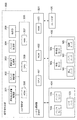
次に、シート処理装置100の主要部の構成について図2を参照しながら説明する。図2は図1のシート処理装置100の主要部の構成を模式的に示す縦断面図である。
Next, the configuration of the main part of the
シート処理装置100は、図2に示すように、複写機300から画像形成されたシートを受け取り、搬送路である搬送パス103に向けて送る入口ローラ対102を有する。入口ローラ対102の手前位置には、シートを検知するための入口センサ101が設けられており、入口センサ101の出力に基づいてシートの受け取りタイミングが検知される。
As shown in FIG. 2, the
上記搬送パス103上には、シートの端部を検知するための横レジストレーションセンサ104が設けられており、当該センサ104は、シフトユニット108の手前位置に配置されている。横レジストレーションセンサ104の出力に基づいて、シートの搬送方向と直交する方向に対して、シートの基準位置からのずれ量が検出される。
A
シフトユニット108は、2つのシフトローラ対105,106を有する。シフトユニット108は、各シフトローラ対105,106がシートを狭侍、搬送している途中で、横レジストレーションセンサ104の出力に基づいて検出されたずれ量分、シートを、シート搬送方向と直交する方向へ移動させる。これにより、シートが基準位置に戻される。
The
シフトユニット108を通過したシートは、互いに対向するように配置されている搬送ローラ110および離間ローラ111により搬送され、フラッパ114を経てバッファローラ対115に向けて搬送される。ここで、シフトユニット108から搬送ローラ110に至るパスの途中位置には、バッファセンサ(第1のセンサ)109が配置されている。バッファセンサ109は、バッファパス(バッファ部)113の上流に設けられる。
The sheet that has passed through the
バッファローラ対115は、1枚のシート、または複数枚のシートが重ねられているシート束を搬送可能なローラ対である。上記バッファローラ対115の出口側には、シートを上搬送パス117または束搬送パス121へ導く位置に移動するフラッパ118が設けられている。ここで、シートがバッファパス113に一時的に退避されることにより滞留される。その後、所定のタイミングで当該シートが次のシート(後続シート)に重ね合わされるように、バッファパス113から送り出されることによってシート束が形成される。上記シートをバッファパス113に退避させるバッファ処理については、後述する。また、バッファローラ対115の出口側には、バッファセンサ(第2のセンサ)116が配置されている。即ち、バッファセンサ109はシートの到達を検知したり、シートの長さを測定するためのセンサとして機能する。バッファセンサ116はシートの到達を検知したり、シート束の長さを測定したりするためのセンサとして機能する。
The
上記上搬送パス117に送られたシートは、上排紙ローラ対120により、上トレイ136上に排出される。上搬送パス117上には、シートの詰まり(ジャム)を検知するためのシートセンサ119が設けられている。
The sheet sent to the
上記束搬送パス121には、1枚のシートまたはシート束が送られ、当該シートまたはシート束は、バッファローラ対122および束搬送ローラ対124により搬送される。そして、シートまたはシート束は、フラッパ125により、サドルパス133または下搬送パス126に送られる。束搬送ローラ対124の手前位置には、シートセンサ123が設けられている。
One sheet or sheet bundle is sent to the
サドルパス133に送られたシートまたはシート束は、サドル入口ローラ対134により、中綴じ処理ユニット135に送られる。この中綴じ処理ユニット135の構成は、周知のものであり、ここでは、その説明は省略する。
The sheet or sheet bundle sent to the
下搬送パス126に送られたシートまたはシート束は、下排紙ローラ対128を経て、平綴じ処理ユニット150に搬送される。平綴じ処理ユニット150は、中間処理トレイ138を有する。シートまたはシート束は、下排紙ローラ対128により、中間処理トレイ138上に排出され、次のシート或いは次のシート束と重ね合わされて束状に積載される。このとき、積載されたシートのそれぞれの端部を揃えるための整合処理が行われる。そして、1セットのコピーを構成する枚数分のシートが中間処理トレイ138上に束状に積載されると、必要に応じて、各シートがステイプラ132により1束に綴じられる。即ち、平綴じ処理が実施される。ステイプラ132により綴じられたシート束または綴じられていないシート束は、束排紙ローラ対130により、下トレイ137上に排出される。
The sheet or sheet bundle sent to the
上記束排紙ローラ対130は、バッファパス113を利用するバッファ処理を実施するか否かに応じて、その当接状態と離間状態とに切り換えられる。この切替は離間機構(図示せず)により行われる。
The bundled paper
ここで、バッファ処理が行われない場合、シートが1枚ずつ中間処理トレイ138上に排出されて積載されることになる。この場合、束排紙ローラ対130は、離間された状態にある。中間処理トレイ138上に排出されたシートは、パドル131およびローレットベルト129により、シートの後端が中間処理トレイ138に設けられている後端ストッパ138aに突き当たるように戻される。これにより、中間処理トレイ138上に積載されたシートの搬送方向の整合が行われることになる。これら、束排紙ローラ対130、パドル131およびローレットベルト129が「整合部」の機能を果たす。
Here, when the buffer processing is not performed, the sheets are discharged and stacked on the
これに対し、バッファ処理が行われた場合、重ね合わされた複数枚のシートからなるシート束が中間処理トレイ138上に排出されることになる。より詳しくは、上記シート束は、その先端が束排紙ローラ対130間に受け入られ、狭持されながら、中間処理トレイ138上に排出される。次いで、束排紙ローラ対130は逆回転し、シート束は、その後端が中間処理トレイ138の後端ストッパ138aに突き当たるように戻される。これにより、中間処理トレイ138上に積載されたシートの搬送方向の整合が行われることになる。
On the other hand, when the buffer process is performed, a sheet bundle composed of a plurality of stacked sheets is discharged onto the
次に、本実施の形態の制御構成について図3を参照しながら説明する。図3は図1の複写機300の制御部950およびシート処理装置100のシート処理装置制御部である制御部501の構成を示すブロック図である。制御部501は、第1の測定部、第2の測定部、調整部および算出部としての機能を果たす。
Next, the control configuration of the present embodiment will be described with reference to FIG. FIG. 3 is a block diagram illustrating the configuration of the
複写機300の制御部(複写機制御部)950は、図3に示すように、CPU回路部305を有する。CPU回路部305は、CPU309、当該CPU309により実行される制御プログラムを格納するROM306およびCPU309の作業領域を提供するRAM307などから構成される。CPU回路部305には、原稿給送装置制御部301、スキャナ制御部302、画像信号処理部303、プリンタ制御部304および操作部308が接続されている。また、CPU回路部305には、シート処理装置100の制御部501を接続するためのインタフェース(図示せず)が設けられており、CPU回路部305は、上記インタフェースを介して、上記シート処理装置100の制御部501と通信を行う。CPU回路部305は、ROM306に格納されている制御プログラムに従って、対応する動作を実行するように、上記各ブロックを制御する。
A control unit (copying machine control unit) 950 of the copying
ここで、原稿給送装置制御部301は、CPU回路部305からの指示に基づいて、原稿給送装置500(図1)の動作を制御する。スキャナ制御部302は、CPU回路部305からの指示に基づいて、スキャナ905(図1)の動作を制御する。
Here, the document
画像信号処理部303は、CPU回路部305からの指示に基づいて、スキャナ905から出力されたRGBのアナログ画像信号をデジタル画像信号に変換し、当該デジタル画像信号に対して各処理を施す。このデジタル画像信号は、ビデオ信号に変換されてプリンタ制御部304に出力される。
The image
プリンタ制御部304は、CPU回路部305からの指示に基づいて、上記画像信号処理部303からのビデオ信号の印刷出力を行うように、各画像形成ユニット914a〜914d、定着器904(図1)などの動作を制御する。
Based on an instruction from the
操作部308は、画像形成に関する各種機能を設定する複数のキー、設定状態を示す情報を表示するための表示部などを有する。操作部308のそれぞれのキー操作に対応するキー信号は、CPU回路部305に入力される。また、操作部308の表示部には、CPU回路部305から出力された、装置状態情報、設定されたモード情報、警告情報などの情報が表示される。
The
制御部501は、シート処理装置100に搭載されており、CPU回路部305からの指示に基づいて、シート処理装置100の動作を制御する。制御部501は、CPU401、ROM402およびRAM403を有する。CPU401は、ROM402に格納されている制御プログラムに従って、センサ群404の各センサの出力を監視しながら、ソレノイド群405の各ソレノイド、モータ群406の各モータの動作を制御する。ここで、上記RAM403は、CPU401の作業領域を提供する。
The
上記センサ群404には、入口センサ101、バッファセンサ109,116、シートセンサ119,123,127(図2を参照)などの複数のセンサが含まれる。ここでは、バッファセンサ109,116、シートセンサ123が図示されており、他のセンサは図示されていない。上記ソレノイド群405には、各フラッパ114,118,125(図2を参照)を動作させるためのソレノイド(図示せず)が含まれる。
The
上記モータ群406には、搬送モータM1、バッファモータM2、排紙モータM3、束排紙モータM4および揺動モータM5が含まれる。また、シフトユニット108、パドル131、ローレットベルト129、ステイプラ132などをそれぞれ駆動するためのモータ(図示せず)が含まれる。また、上トレイ136、下トレイ137の各トレイをそれぞれ昇降動作させるためのモータ(図示せず)が含まれる。
The
ここで、上記搬送モータM1は、入口ローラ対102、シフトローラ対105,106、搬送ローラ110をそれぞれ連動させて回転駆動させるためのモータである。上記バッファモータM2は、各バッファローラ対112,115をそれぞれ連動させて回転駆動させるためのモータである。上記排紙モータM3は、上排紙ローラ対120、バッファローラ対122、束搬送ローラ対124、下排紙ローラ対128をそれぞれ回転駆動させるためのモータである。上記束排紙モータM4は、束排紙ローラ対130を回転駆動するためのモータである。上記揺動モータM5は、上記束排紙ローラ対130を離間動作させるためのモータである。
Here, the conveyance motor M1 is a motor for rotating the
次に、本実施の形態におけるバッファ処理について図4〜図6を参照しながら説明する。図4はバッファ処理時におけるバッファ対象のシートの搬送状態を模式的に示す図である。図5はバッファ処理時におけるバッファ対象のシートと当該バッファ対象のシートに続く後続シートの搬送状態を模式的に示す図である。図6はバッファ処理時におけるバッファ対象のシートと後続シートを重ね合わせて搬送する状態を模式的に示す図である。 Next, buffer processing in the present embodiment will be described with reference to FIGS. FIG. 4 is a diagram schematically illustrating a conveyance state of a buffer target sheet during buffer processing. FIG. 5 is a diagram schematically showing a conveyance state of a buffer target sheet and a succeeding sheet following the buffer target sheet during buffer processing. FIG. 6 is a diagram schematically illustrating a state in which a buffer target sheet and a subsequent sheet are conveyed while being overlapped during buffer processing.
平綴じ処理の場合、複写機300からシート処理装置100には、一定の間隔でシートが排出され、平綴じ処理ユニット150に搬送される。そして、シートは、中間処理トレイ138上に束状に積載される。束状に積載されたシートに対しては、それぞれの端部を揃えるための整合処理が行われ、この整合処理後に、シート束がステイプラ132により綴じられる。そして、綴じられたシート束は、下トレイ137に排紙される。
In the case of side stitching processing, sheets are discharged from the copying
ここで、平綴じ処理の実施に要する時間が上記シート排出間隔に相当する時間より長いと、1部目のシート束への平綴じ処理の実施中に、2部目の最初のシートが中間処理トレイ138に排出されることになる。そのため、1部目のシート束への平綴じ処理を完了することができない。
Here, if the time required for the side stitching process is longer than the time corresponding to the sheet discharge interval, the first sheet of the second set is subjected to the intermediate process during the side stitching process for the first sheet bundle. It is discharged to the
そこで、上記平綴じ処理の実施時間を確保するために、シート処理装置100内で、シートをバッファパス113に一時的に滞留させるバッファ処理が行われる。
Therefore, in order to secure the execution time of the above-described side stitching process, a buffer process for temporarily retaining the sheet in the
具体的には、図4に示すように、複写機300からシート処理装置100へバッファ対象のシートS1(先行シート)が搬入されたとする。このシートS1は、入口ローラ対102、シフトユニット108、搬送ローラ110および離間ローラ111、フラッパ114を経て、バッファローラ対115に向けて搬送される。ここで、フラッパ114は、対応するソレノイドにより、シートS1をバッファローラ対115に導く動作状態に保持されている。また、フラッパ118が、対応するソレノイドにより、束搬送パス121を選択する動作状態に保持されている。
Specifically, as shown in FIG. 4, it is assumed that a sheet S1 (preceding sheet) to be buffered is carried from the copying
上記シートS1の搬送途中においてバッファセンサ109の出力に基づいてシートS1の先端がバッファセンサ109に到達したことが検知されると、この検知のタイミングを基準として、シートS1の搬送量の計測が開始される。このS1の搬送量の計測は、シートS1の搬送速度(搬送モータM1の回転速度)および上記検知のタイミングからの経過時間に基づいて行われる。
When it is detected that the leading edge of the sheet S1 has reached the
上記計測されたシートS1の搬送量が所定量であるZ1(mm)に達すると、バッファローラ対115を正転させるタイミングが到来したと判断され、バッファローラ対115を正転させるようにバッファモータM2が起動される。これにより、シートS1は、フラッパ118を経て、束搬送パス121に導かれる。ここで、上記バッファモータM2は、各バッファローラ対112,115を連動させて回転、停止させるので、バッファローラ対115が正転すると、それに連動してバッファローラ対112は正転する。
When the measured transport amount of the sheet S1 reaches a predetermined amount Z1 (mm), it is determined that the timing for normal rotation of the
次いで、バッファセンサ116の出力に基づいてシートS1の先端がバッファセンサ116に到達したことが検知されると、この検知のタイミングを基準として、シートS1の搬送量の計測が開始される。このS1の搬送量の計測は、シートS1の搬送速度(バッファモータM2の回転速度)および上記検知のタイミングからの経過時間に基づいて行われる。
Next, when it is detected that the leading edge of the sheet S1 has reached the
上記計測されたシートS1の搬送量がZ2(mm)に達すると、バッファローラ対115を停止させるタイミングが到来したと判断され、バッファモータM2が停止される。即ち、バッファローラ対115が停止され、上記シートS1の搬送が停止される。ここで、上記搬送量Z2は、シートS1の後端がPA位置に到達するまでの搬送量である。上記PA位置は、少なくとも搬送パス103とバッファパス113が合流する位置より下流側、即ちフラッパ114より下流側に位置にする。よって、上記搬送量Z2は、シートS1の搬送方向のサイズに応じて決定される量であり、このシートS1の搬送方向のサイズは、CPU回路部305からあらかじめ通知される。
When the measured transport amount of the sheet S1 reaches Z2 (mm), it is determined that the timing for stopping the
上記シートS1の搬送が停止されると、フラッパ114が対応するソレノイドにより、駆動され、フラッパ114は、シートS1をバッファパス113に導く位置に移動される。また、停止されているバッファローラ対115が逆転するようにバッファモータM2が起動される。これにより、図5に示すように、シートS1は、フラッパ114を経てバッファパス113に導かれる。そして、シートS1は、バッファローラ対115に連動して逆転するバッファローラ対112により、その一部がバッファパス113内に引き込まれるように、搬送される。
When the conveyance of the sheet S1 is stopped, the
シートS1の先端がバッファセンサ116を通過し、予め決められているPB位置に到達するまでシートS1の搬送が行われる。また、シートS1の先端がPB位置に到達すると、シートS1の搬送が停止される。即ち、シートS1は、バッファセンサ116から搬送量Z3(mm)分搬送され停止する。ここで、上記シートS1の搬送量の計測は、シートS1の搬送速度(バッファモータM2の回転速度)およびシートS1の先端がバッファセンサ116を通過したことを検知したタイミングからの経過時間に基づいて行われる。
The sheet S1 is conveyed until the leading edge of the sheet S1 passes through the
バッファセンサ116からのシートS1の搬送量がZ3(mm)に達すると、バッファローラ対112、115を停止させるタイミングが到来したと判断される。そして、バッファモータM2が停止され、バッファローラ対112が停止される。これにより、シートS1は、その先端がPB位置に到達した状態で停止される。即ち、シートS1は、バッファパス113に退避させられることにより一時的に滞留される。上記シートS1の搬送が停止されると、フラッパ114は対応するソレノイドにより駆動され、シートS1をバッファローラ対115に導く位置に戻される。
When the conveyance amount of the sheet S1 from the
上記シートS1のバッファパス113に退避されると、当該シートS1に続く次のシートS2(後続シート)がシート処理装置100内に搬入され、バッファローラ対115に向けて搬送される。ここで、シートS2の先端が、所定位置であるバッファセンサ109の位置に到達したことが検知されてからシートS2が搬送量Z1(mm)搬送されると、バッファローラ対112が正転する。そのため、バッファパス113にあるシートS1がバッファパス113から送り出される。これにより、図6に示すように、シートS1は、その搬送速度がシートS2の搬送速度と同じになった状態で、バッファローラ対115の手間位置(上記PB位置の下流位置)で、シートS2と重ね合わされる。そして、シートS1とシートS2は、重ね合わされた状態で(1つのシート束として)、束搬送パス121に向けて搬送される。ここで、シートS1は、その先端がシートS2の先端と所定のオフセット量を有する状態で重ね合わされる。即ち、シートS2の先端がシートS1の先端よりも所定量先行した状態で、シートS1とS2とが重ね合わされる。
When the sheet S1 is retracted to the
上記搬送量Z1は、バッファローラ対115,112を回転させるタイミング(バッファモータM2を起動するタイミング)を決定する変数である。換言すれば、上記搬送量Z1は、バッファパス113にあるシートS1をバッファパス113から送り出すためのバッファモータM2を起動する起動タイミングである。この搬送量Z1を調整することによって、それぞれのシートS1,S2が所定のオフセット量(ずれ量)で重なり合うようにすることができる。上記搬送量Z1の調整(即ちオフセット量の調整)については、後述する。
The carry amount Z1 is a variable that determines the timing for rotating the
ここでは、2枚のシートS1,S2を重ね合わせる場合を説明したが、これに限定されることはなく、3枚以上のシートを重ね合わせることも可能である。例えば、次のシートS3を、重ね合わされたシートS1,S2に重ね合わせる場合は、上述した動作と同様の動作により、重なり合うシートS1,S2がバッファパス113内に退避させられる。次いで、シートS3の先端がバッファセンサ109に到達したことが検知されてからシートS3が搬送量Z1分搬送されると、シートS1,S2が重なり合ったままの状態でバッファパス113から送り出される。そして、シートS1,S2とシートS3が重ね合わされて搬送される。このとき、シートS3は、その先端がシートS2の先端と所定のオフセット量を有する状態で重ね合わされる。
Here, the case where the two sheets S1 and S2 are overlapped has been described, but the present invention is not limited to this, and it is possible to overlap three or more sheets. For example, when the next sheet S3 is overlaid on the overlaid sheets S1 and S2, the overlapping sheets S1 and S2 are retracted into the
このように、バッファ処理により重ね合わされた複数枚のシートは、1つのシート束として、バッファローラ対122および束搬送ローラ対124により、平綴じ処理ユニット150に搬送される。
In this way, the plurality of sheets superposed by the buffer process are conveyed to the flat
次に、シート処理装置100の制御部501によるシート搬送制御について図7および図8を参照しながら説明する。図7および図8はシート処理装置100の制御部501によるシート搬送制御の手順を示すフローチャートである。図7および図8のフローチャートに示す手順は、制御部501のCPU401により、ROM402に格納されているプログラムに従って実行されるものである。
Next, sheet conveyance control by the
本実施の形態においては、複写機300からシート処理装置100へシートが1枚ずつ排出され、シート処理装置100においては、複写機300から排出されたシートを搬送する制御および後処理の制御が行われる。そのため、複写機300の制御部950は、シート毎に、画像形成開始を示すスタート信号を発行し、シート処理装置100の制御部501に送信する。また、上記シート毎のスタート信号とともに、制御情報が制御部950から制御部501に送信される。この制御情報には、シートに対して実施する処理(モード)を示す情報、および、当該シートが何部目の何枚目のシートであるかを示す情報が含まれる。制御部501は、上記制御情報に基づいて、制御を行う。
In the present embodiment, sheets are discharged from the copying
具体的には、図7に示すように、制御部501(CPU401)は、複写機300の制御部950からのスタート信号を受信するのを待つ(ステップS101)。上記スタート信号を受信すると、制御部501は、搬送モータM1を起動する(ステップS102)。この搬送モータM1の起動により、入口ローラ対102、各シフトローラ対105,106、搬送ローラ110が回転駆動され、複写機300から搬入されたシートがバッファローラ対115に向けて搬送される。ここで、シフトユニット108は、搬送されてきたシートの基準位置からのずれを調整する。また、フラッパ114は、通常時は、シートをバッファローラ対115に導く位置にあり、バッファ処理時に、シートをバッファパス113に導く位置に移動される。
Specifically, as shown in FIG. 7, the control unit 501 (CPU 401) waits to receive a start signal from the
次いで、制御部501は、バッファセンサ109からのオン信号が入力されるのを待つ(ステップS103)。ここで、バッファセンサ109からのオン信号が入力されると、制御部501は、シートの搬送方向の長さAの計測を開始する(ステップS104)。このシートの搬送方向長さAの計測は、制御部501にバッファセンサ109からのオン信号が入力された時点からオフ信号が入力されるまでの時間(バッファセンサ109の検知結果)と、シートの搬送速度(搬送モータM1の回転数)に基づいて行われる。更に制御部501は、シートの搬送量の計測も開始し、当該搬送量がZ1(mm)に達するのを待つ(ステップS105)。そして、シートの搬送量がZ1(mm)に達すると、制御部501は、バッファモータM2および排紙モータM3を起動する(ステップS106)。ここでは、バッファモータM2により、バッファローラ対115が正転される。このバッファローラ対115の正転に連動して、バッファローラ対112が正転される。また、排紙モータM3により、上排紙ローラ対120、バッファローラ対122、束搬送ローラ対124、下排紙ローラ対128がそれぞれ回転される。
Next, the
次いで、制御部501は、制御部950からの制御情報に基づいて、上記シートに対して実施する処理(モード)として、ノンソートモード、平綴じモード、中綴じモードのいずれが設定されているかを判別する(ステップS107)。ここで、ノンソートモードが設定されている場合、制御部501は、フラッパ118に対応するソレノイドを駆動し、フラッパ118を、シートを上搬送パス117へ導く位置に移動させる(ステップS108)。したがって、ノンソートモードが設定されている場合、シートは、上搬送パス117へ導かれ、上排紙ローラ対120により、上トレイ136上に排出される。このようにノンソートモードの場合、バッファ処理は行われず、シートは、1枚ずつ上トレイ136上に排出される。
Next, based on the control information from the
上記ステップS107において中綴じモードが設定されていると判別された場合、制御部501は、シートを中綴じ処理ユニット135に搬送し、シートの中綴じ処理を実施するように制御する(ステップS109)。この場合、各フラッパ118,125により、束搬送パス121からサドルパス133へ至る搬送パスが形成され、シートが中綴じ処理ユニットへ搬送される。この中綴じ処理の制御についての説明は、省略する。
When it is determined in step S107 that the saddle stitching mode is set, the
上記ステップS107において平綴じモードが設定されていると判別された場合、図8に示すように、制御部501は、シートが束搬送パス121から下搬送パス126へ搬送されるように不図示のソレノイドを制御する(ステップS110)。ここでは、フラッパ118が対応するソレノイドにより、シートを束搬送パス121に導く位置に、フラッパ125が対応するソレノイドにより、シートを下搬送パス126に導く位置に、それぞれ移動される。
If it is determined in step S107 that the side stitching mode is set, as shown in FIG. 8, the
次いで、制御部501は、制御部950からの制御情報に基づいて、シートが1部目(シートの第1のセット)のシートであるか否かを判定する(ステップS111)。ここで、上記シートが1部目のシートであると判定された場合、制御部501は、シートセンサ123からのオン信号が入力されるのを待つ(ステップS120)。シートセンサ123からのオン信号が入力されると、制御部501は、上記制御部950からの制御情報に基づいて、シート束がシートセンサ123で検知されたか否かを判定する(ステップS121)。1部目のシートに関しては、バッファされないため、ステップS121ではシート束でないと判定される。制御部501は、中間処理トレイ138上にシートを積載するための制御を行う処理を行う(ステップS123)。ここでは、束搬送パス121および下搬送パス126を経て下排紙ローラ対128により中間処理トレイ138にシートが排紙される。ここで、制御部501がシートセンサ123の出力に基づいてシートがシートセンサ123に到達したことを検出すると、束排紙ローラ対130が離間するように、揺動モータM5を起動する。そして、制御部501は、シートセンサ127の出力に基づいてシートの後端が下排紙ローラ対128を抜けたことを検出すると、パドル131およびローレットベルト129を駆動する。これにより、中間処理トレイ138上に排紙されたシートは、その後端が中間処理トレイ138の後端ストッパ138aに突き当たるように戻される。
Next, the
このようにして、1部目のシートに関しては、バッファ処理は行われず、1枚ずつ中間処理トレイ138上に排紙される。
In this way, the first sheet is not subjected to buffer processing and is discharged onto the
一方、ステップS111で、シートが1部目のシートでないと判断された場合、制御部501は、制御部950からの制御情報に基づいて、シートがバッファ対象のシートであるか否かを判定する(ステップS112)。例えば、2部目以降の各部のシートに関しては、その1枚目のシートと2枚目のシートがバッファ対象のシートであるとする。従って、2部目以降の各部の3枚目以降のシートはバッファ対象のシートでないと判別される。一般的に、バッファ対象のシートは、平綴じ処理に要する時間と複写機300から搬送されてくるシートの搬送間隔とに基づいて決定される。シートがバッファすべきシートでないと判定された場合、このシートは、バッファされた1枚目および2枚目のシートに重ね合わされる3枚目のシートか、または4枚目以降のシートである。この場合、制御部501は、シートセンサ123からのオン信号が入力されるのを待つ(ステップS120)。シートセンサ123からのオン信号が入力されると、制御部501は、上記制御部950からの制御情報に基づいて、シート束(1枚目〜3枚目のシートが重ね合わされたシート束)がシートセンサ123で検知されたか否かを判定する(ステップS121)。シートセンサ123でシート束が検知された場合、制御部501はオフセット量調整処理を実行する(ステップS122)。オフセット調整処理については後述する。シートセンサ123で1枚のシートが検知された場合、上述したようにステップS123で中間処理トレイ138へのシートの積載が行われる。
On the other hand, when it is determined in step S111 that the sheet is not the first sheet, the
そして、制御部501は、制御部950からの制御情報に基づいて、中間処理トレイ138に排紙されたシートが1部の最終のシートであるか否かを判定する(ステップS124)。ここで、シートが1部の最終のシートでない場合、制御部501は、ステップS103へ戻り、次のシートの到達を待つ。
Then, the
上記ステップS124においてシートが1部の最終のシートであると判定された場合、制御部501は、ステイプラ132により中間処理トレイ138上に積載されているシート束を綴じる(ステップS125)。そして、制御部501は、揺動モータM5を起動して上記綴じられたシート束を狭持する位置に束排紙ローラ対130を移動させた後に、束排出モータM4を起動して束排紙ローラ対130を回転させる(ステップS126)。これにより、上記綴じられたシート束は、下トレイ137に排紙される。次に、制御部501は、指定された部数の後処理が終了したか否かを判定し(ステップS127)、残りの部があれば、ステップS103へ戻り、次のシートの到達を待つ。一方、指定部数の後処理が終了していれば、制御部501は、処理を終了する。
If it is determined in step S124 that the sheet is one final sheet, the
上記ステップS112においてシートがバッファ対象のシートであると判定された場合、制御部501は、バッファセンサ116からのオン信号(シートの先端が検知されたことを示す信号)が入力されるのを待つ(ステップS113)。ここで、バッファセンサ116からのオン信号が入力されると、制御部501は、シートを搬送量Z2(mm)分搬送した後に、バッファモータM2を停止させる(ステップS114)。これにより、バッファローラ対115は停止し、上記シートは、その後端がPA位置に到達した状態で停止されることになる(図4)。
When it is determined in step S112 that the sheet is a buffer target sheet, the
次いで、制御部501は、フラッパ114に対応するソレノイドを駆動し、フラッパ114を、シートをバッファパス113に導く位置に移動させる(ステップS115)。そして、制御部501は、バッファローラ対115を逆転させるように、バッファモータM2を起動する(ステップS116)。このバッファローラ対115の逆転に連動してバッファローラ対112は、逆転する。これにより、シートは、フラッパ114を経て、その後端からバッファパス113内に導かれる。
Next, the
次いで、制御部501は、バッファセンサ116からのオフ信号(シートの先端がバッファセンサ116を通過したことを示す信号)が入力されるのを待つ(ステップS117)。ここで、バッファセンサ116からオフ信号が入力されると、制御部501は、上記シートを搬送量Z3(mm)分搬送した後に、バッファモータM2を停止させる(ステップS118)。これにより、バッファローラ対115は停止し、上記シートは、その先端が上記PB位置に到達した状態で停止されることになる(図5)。即ち、シートは、一時的に滞留させられることになる。
Next, the
次いで、制御部501は、フラッパ114に対応するソレノイドを駆動し、フラッパ114を、元の位置へ復帰させる(ステップS119)。そして、制御部501は、ステップS103へ戻り、次のシートの到達を待つ。
Next, the
次に、シートの搬送の具体例について説明する。例えば1部のコピーセットがシートS1〜S5の5枚のシートからなり、2部のコピーセットを出力する場合を例にして各シートS1〜S5の搬送を説明する。ここでは、シートS1,S2の2枚のシートをバッファ対象のシートであるとする。 Next, a specific example of sheet conveyance will be described. For example, the conveyance of each sheet S1 to S5 will be described by taking as an example a case where one copy set is composed of five sheets S1 to S5 and two copy sets are output. Here, it is assumed that the two sheets S1 and S2 are buffer target sheets.
1部目に関しては、各シートS1〜S5が1部目のシートであると判定され、その後1枚ずつ中間処理トレイ138に積載される。そして、中間処理トレイ138上に最終のシートであるシートS5が積載されると、ステイプラにより、各シートS1〜S5は1束に綴じられ、綴じられたシート束(シートS1〜S5)は、下トレイ137に排紙される。
Regarding the first copy, it is determined that each of the sheets S1 to S5 is the first copy, and is then stacked one by one on the
2部目に関しては、シートS1,S2のバッファが行われる。ここで、シートS1がバッファすべきシートであると判定され、当該シートS1は搬送途中でバッファパス113内に退避させられる。バッファパス113内のシートS1は、現在設定されるタイミング(搬送量Z1)でバッファパス113から送り出され、続いて搬入されたシートS2とオフセットされた状態で重ね合わされる。そして、シートS1とシートS2は、1つの束として搬送され、その途中でバッファパス113に戻される。これにより、シートS1,S2がバッファパス113内に退避させられる。
For the second copy, sheets S1 and S2 are buffered. Here, it is determined that the sheet S1 is a sheet to be buffered, and the sheet S1 is retracted in the
バッファパス113内の重ね合わされたシートS1,S2は、その時点で既に設定されているタイミングでバッファパス113から送り出され、続いて搬入されたシートS3とオフセットされた状態で重ね合わされる。そして、シートS1〜S3は、重ね合わされた1つのシート束として搬送される。
The superposed sheets S1 and S2 in the
各シートS1〜S3が重ね合わされたシート束は、それに含まれるシートS3がバッファ対象のシートではないので、バッファ対象のシートでないと判定される。よって、各シートS1〜S3が重ね合わされたシート束は、中間処理トレイ138へ向けて搬送され、中間処理トレイ138上に積載される。
The sheet bundle in which the sheets S1 to S3 are overlaid is determined not to be a buffer target sheet because the sheet S3 included therein is not a buffer target sheet. Therefore, the sheet bundle in which the sheets S1 to S3 are overlaid is conveyed toward the
シートS3に続いて各シートS4,S5が1枚ずつ搬入される。シートS4,S5は、バッファ対象のシートではないので、1枚ずつ中間処理トレイ138に積載される。そして、中間処理トレイ138上に2つ目のコピーの最終のシートであるシートS5が積載されると、ステイプラ132により、各シートS1〜S5は1束に綴じられ、綴じられたシート束(シートS1〜S5)は、下トレイ137に排紙される。
Following the sheet S3, the sheets S4 and S5 are carried in one by one. Since the sheets S4 and S5 are not buffer target sheets, they are stacked one by one on the
次に、オフセット量調整処理(図8のステップS122)の詳細について図9を参照しながら説明する。 Next, details of the offset adjustment process (step S122 in FIG. 8) will be described with reference to FIG.
オフセット調整処理においては、制御部501は、シート束(1枚目〜3枚目のシートが重ね合わされたシート束)の搬送方向長さB(mm)を計測する(ステップS201)。このシート束の搬送方向長さBの計測は、バッファセンサ116からオン信号が入力された時点からオフ信号が入力されるまでの時間(バッファセンサ116の検知結果)と、シートの搬送速度(バッファモータM2の回転数)に基づいて行われる。
In the offset adjustment process, the
次に、制御部501は、それぞれ測定結果である、シート束の搬送方向長さBとステップS104で求めたシートの搬送方向長さA(1枚目のシートの搬送方向長さ)の差をオフセット量(ずれ量)Cとして算出する(ステップS202)。シートの搬送方向長さAとして1枚目のシートを採用する理由は、本実施形態では、3枚のシートを重ね合わせたシート束の後端側が1枚目のシートとなる様にシートをオフセットさせているからである。即ち、2枚目のシートはシート束の先端にも後端にもならないため、2枚目のシートはシート束の長さBの測定には影響しない。次に、制御部501は、オフセット目標値(目標量)Dと上記ステップS202で算出されたオフセット量Cの差を差分E1として算出する(ステップS203)。この差分E1は、RAM403に保持される。
Next, the
次いで、制御部501は、上記差分E1の絶対値が許容値Fより大きいか否かを判定する(ステップS204)。ここで、差分E1の絶対値が許容値Fより大きくなければ、制御部501は、オフセット量を調整する必要がないため、本処理を終了する。これにより、現在設定されている搬送量Z1は、変更されずに、次回の搬送量Z1として設定される。
Next, the
これに対し、上記ステップS204において差分E1の絶対値が許容値Fより大きいと判定された場合、制御部501は、その時点で設定されている搬送量Z1(バッファモータM2の起動タイミングを決定する値)を変更する(ステップS205)。ここでは、搬送量Z1が、その時点で設定されている搬送量Z1に差分E1を加えた搬送量に変更され、この変更された搬送量Z1が次回のシート重ね合わせの際の搬送量Z1として設定される。これは、オフセット後のシート束は、シート束の中の上側にあるシートの先端が下側のシートの先端より搬送方向下流側にずれた状態にあることを想定しているからである。そして、制御部501は、本処理を終了する。
On the other hand, when it is determined in step S204 that the absolute value of the difference E1 is larger than the allowable value F, the
このような搬送量Z1の設定変更は、滞留させたシートの搬送のタイミングを、差分E1に応じた時間分、早く或いは遅くすることに相当する。 Such a change in the setting of the transport amount Z1 corresponds to the timing of transporting the stayed sheet being advanced or delayed by a time corresponding to the difference E1.
以上のように、本実施形態では、シート処理装置でのシートの搬送中に、複数枚のシートを重ね合わせる際のオフセット量を測定し、測定した結果と目標値との差分を次回の重ね合わせの際のシート搬送制御にフィードバックする。これにより、画像形成装置の定着器を通過したシートが伸縮したとしても、オフセット量のばらつきを少なくすることができる。また、定形サイズのシートの断裁精度が悪く、シートの長さが呼称値と一致していない場合でも、オフセット量のばらつきを少なくすることができる。 As described above, in the present embodiment, during the conveyance of the sheet in the sheet processing apparatus, the offset amount when overlapping a plurality of sheets is measured, and the difference between the measured result and the target value is determined for the next overlap. Is fed back to the sheet conveyance control. As a result, even if the sheet that has passed through the fixing device of the image forming apparatus expands and contracts, variation in the offset amount can be reduced. Further, even when the cutting accuracy of the standard size sheet is poor and the length of the sheet does not coincide with the nominal value, variation in the offset amount can be reduced.
上述した実施形態では、1部目のシートに対してはバッファ処理を実行しないものとして説明した。しかし、1部目のシートに対しても上述したバッファ処理(シートの重ね合わせ)を行い、ステップS122のオフセット量調整処理を実行しても良い。 In the above-described embodiment, the buffer process is not executed for the first sheet. However, the above-described buffer process (sheet superposition) may be performed on the first sheet, and the offset amount adjustment process in step S122 may be performed.
また、上述した実施形態では、平綴じモードが指定されている場合に、オフセット量調整処理を実行するものとして説明した。しかし、平綴じモードが指定されているか否かにかかわらず、バッファ処理を行う必要がある場合にオフセット量調整処理を実行しても良い。即ち、中綴じモードや中間処理トレイ138へシートを排出するモードのときにオフセット量調整処理を実行すればよい。
In the above-described embodiment, the offset amount adjustment process is executed when the side stitching mode is designated. However, the offset amount adjustment processing may be executed when it is necessary to perform buffer processing regardless of whether the side stitching mode is designated. That is, the offset amount adjustment process may be executed in the saddle stitching mode or the mode for discharging the sheet to the
また、装置の異常によりオフセット量が大きくなりすぎた場合、即ち、算出したオフセット量Cが所定値を超えている場合、オフセット調整処理を行わずに、異常(エラー)があることを操作部308へ表示する等によって報知するようにしても良い。
Further, when the offset amount becomes too large due to an abnormality of the apparatus, that is, when the calculated offset amount C exceeds a predetermined value, the
また、オフセット量調整処理の機能をなくし、オフセット量Cが所定値を超えた場合に異常があることを操作部308に表示し、バッファ処理が必要なシート搬送を禁止するようにしても良い。この場合、オフセット量Cが所定値以下であれば、通常のシート搬送制御が行われる。
Further, the function of the offset amount adjustment processing may be eliminated, and when the offset amount C exceeds a predetermined value, an error is displayed on the
(第2の実施の形態)
次に本発明の第2の実施の形態を説明する。上述の第1の実施の形態のように、通常のシート搬送制御時(画像形成動作時)に上述したオフセット量調整処理を実行する代わりに、サービスマンやユーザが画像形成動作とは独立した別のタイミングでオフセット量調整処理を実行しても良い。例えば、操作部308から調整モードとしてのオフセット量調整処理の実行を指示する。この指示により、画像形成装置は複数枚の白紙のシートをシート処理装置へ排出し、シート処理装置は受け取ったシートのバッファ処理を行う。このときの制御は図7、図8と同様に実行される。但し、ステップS127での指定部数は2部とする。また、ステップS122のオフセット量調整処理として、図10、図11に示す制御処理が実行される。本実施の形態は、第1の実施の形態とは、主としてこの処理においてのみ相違し、構成は同じである。したがって、構成の説明を省略し、構成要素は同じ符合で示す。
(Second Embodiment)
Next, a second embodiment of the present invention will be described. As in the first embodiment described above, instead of executing the above-described offset amount adjustment processing during normal sheet conveyance control (image forming operation), a serviceman or a user can perform a separate operation from the image forming operation. The offset amount adjustment processing may be executed at the timing. For example, the
以下図10、図11を用いて、調整モードとしてのオフセット量調整処理について説明する。 Hereinafter, the offset amount adjustment processing as the adjustment mode will be described with reference to FIGS.
制御部501は、シート束(1枚目〜3枚目のシートが重ね合わされたシート束)の搬送方向長さB(mm)を計測する(ステップS301)。このシート束の搬送方向長さBの計測は、ステップS201と同様である。
The
次いで、制御部501は、差分確認ビットが1であるか否かを判定する(ステップS302)。差分確認ビットとは、測定したオフセット量と目標値との差分の絶対値が許容値以下となったことを示すものである。差分確認ビットは、その値が1であれば、差分が許容値以下であることを示し、1以外の値であれば、差分が許容値以下であることが確認されていないことを示す。
Next, the
ステップS302において差分確認ビットが1でないと判定された場合、制御部501は、ステップS202、S203と同様の処理を行う(ステップS303,S304)。
When it is determined in step S302 that the difference confirmation bit is not 1, the
次いで、制御部501は、上記差分E1の絶対値が許容値Fより大きいか否かを判定する(ステップS305)。ここで、差分E1の絶対値が許容値Fより大きくなければ、制御部501は、調整終了ビットを1に設定し(ステップS306)、本処理を終了する。これにより、現在設定されている搬送量Z1は、変更されずに、次回の搬送量Z1として設定される。
Next, the
これに対し、ステップS305において差分E1の絶対値が許容値Fより大きいと判定された場合、制御部501は、ステップS205と同様の処理を行う(ステップS307)。そして、制御部501は、差分確認ビットを1に設定し(ステップS308)、本処理を終了する。
On the other hand, when it is determined in step S305 that the absolute value of the difference E1 is greater than the allowable value F, the
上記ステップS302において差分確認ビットが1であると判定された場合、制御部501は、シート束の搬送方向長さBとシートの搬送方向長さAの差を、オフセット量Cとして算出する(ステップS309)。そして、制御部501は、オフセット目標値Dと上記ステップS309で算出されたオフセット量Cの差を差分E2として算出する(ステップS310)。
When it is determined in step S302 that the difference confirmation bit is 1, the
次いで、制御部501は、前回算出した差分E1の絶対値と今回測定した差分E2の絶対値と間で次の関係式(下記数式1)を成立するか否かを判定する(ステップS311)。
Next, the
[数1]
|E1|−|E2|<0
ここで、|E1|−|E2|<0の関係式が成立する場合は、制御部501は、E2の値が0より小さいか否かを判定する(ステップS312)。|E1|−|E2|<0かつE2<0の関係式が成立する場合は、前回の搬送量Z1の変更(ステップS307)によって、差分がさらに増加している場合である。即ち、この場合は、シータ束の中の上側にあるシート(2枚目のシート)の先端が下のシート(1枚目のシート)の先端より搬送方向下流側により大きくずれた状態にある場合である。そこで、制御部501は、その時点で設定されている搬送量Z1を再度変更する(ステップS313)。ここでは、搬送量Z1が、その時点で設定されているZ1から差分E2の絶対値を減算しオフセット目標値Dを加算した値(Z1−|E2|+D)に変更される。この変更された搬送量Z1は、通常のシート搬送制御におけるバッファ処理時の搬送量Z1として設定される。そして、制御部501は、差分確認ビットの値をクリアし(ステップS316)、本処理を終了する。
[Equation 1]
| E1 |-| E2 | <0
Here, when the relational expression | E1 | − | E2 | <0 holds, the
上記ステップS311において|E1|−|E2|<0の関係式が成立しないと判定された場合、制御部501は、差分E2の絶対値が許容値Fより大きいか否かを判定する(ステップS314)。ここで、差分E2の絶対値が許容値Fより大きい場合、制御部501は、その時点で設定されている搬送量Z1を変更する(ステップS315)。ここでは、搬送量Z1が、その時点で設定されている搬送量Z1に差分E2を加えた搬送量に変更され、この変更された搬送量Z1は、通常のシート搬送制御におけるバッファ処理時の搬送量Z1として設定される。そして、制御部501は、差分確認ビットの値をクリアし(ステップS316)、本処理を終了する。
When it is determined in step S311 that the relational expression | E1 | − | E2 | <0 is not satisfied, the
上記ステップS314において差分E2の絶対値が許容値Fより大きくないと判定された場合、制御部501は、差分確認ビットの値をクリアする(ステップS317)。そして、制御部501は、調整終了ビットを1に設定し(ステップS306)、本処理を終了する。
When it is determined in step S314 that the absolute value of the difference E2 is not greater than the allowable value F, the
このように、調整モードとしてのオフセット量調整処理において、通常のシート搬送制御時のバッファ対象のシートと後続シートとが重ね合わされた際のオフセット量が調整される。このオフセット量の調整においては、その時点で設定されている起動タイミング(Z1)でのオフセット量が許容範囲内であるか否かに応じて、起動タイミング(Z1)が変更され、該変更された起動タイミングが次回の起動タイミングとして設定される。その結果、バッファバッファ対象のシートと後続シートとを許容されるオフセット量で確実に重ね合わすことができ、整合不良の発生を抑制することができる。 As described above, in the offset amount adjustment processing as the adjustment mode, the offset amount when the buffer target sheet and the subsequent sheet are overlapped at the time of normal sheet conveyance control is adjusted. In the adjustment of the offset amount, the activation timing (Z1) is changed depending on whether or not the offset amount at the activation timing (Z1) set at that time is within the allowable range. The activation timing is set as the next activation timing. As a result, it is possible to reliably overlap the buffer buffer target sheet and the succeeding sheet with an allowable offset amount, and to suppress the occurrence of misalignment.
なお、上述した調整モードとしてのオフセット量調整処理を、通常のシート搬送制御時(画像形成動作時)のオフセット量調整処理として実行しても良い。 Note that the offset amount adjustment process as the adjustment mode described above may be executed as an offset amount adjustment process during normal sheet conveyance control (at the time of image forming operation).
(その他の実施例)
また、本発明は、以下の処理を実行することによっても実現される。即ち、上述した実施形態の機能を実現するソフトウェア(プログラム)を、ネットワーク又は各種記憶媒体を介してシステム或いは装置に供給し、そのシステム或いは装置のコンピュータ(またはCPUやMPU等)がプログラムを読み出して実行する処理である。
(Other examples)
The present invention can also be realized by executing the following processing. That is, software (program) that realizes the functions of the above-described embodiments is supplied to a system or apparatus via a network or various storage media, and a computer (or CPU, MPU, etc.) of the system or apparatus reads the program. It is a process to be executed.
100 シート処理装置
109 バッファセンサ
113 バッファパス
116 バッファセンサ
138 中間処理トレイ
501 制御部
DESCRIPTION OF
Claims (8)
前記画像形成装置から排出されたシートを一時的に滞留させ、滞留したシートと後続のシートとを前記シートの搬送方向にずれた状態で重ね合わせるバッファ部と、
前記バッファ部で重ね合わされて搬送されるシート束が積載されるトレイと、
前記トレイに積載されたシート束を搬送方向に整合する整合部と、
前記バッファ部に滞留されるべきシートの搬送方向における長さを測定する第1の測定部と、
前記重ね合わされたシート束の搬送方向における長さを測定する第2の測定部と、
前記第2の測定部の測定結果から前記第1の測定部の測定結果を減算した値であるオフセット量が目標量となるように、前記バッファ部でシート束に重ね合わせるタイミングの調整値を決定する調整部と、を有し、
前記調整部は、前記第1の測定部及び前記第2の測定部の測定結果に基づいて、第1のシート束におけるオフセット量を前記目標量から減算した第1の値と、該第1の値に基づいて調整した後続の第2のシート束におけるオフセット量を前記目標量から減算した第2の値とを求め、前記第1の値の絶対値から前記第2の値の絶対値を減算した結果が0より小さくなり、且つ前記第2の値が負である場合、決定済みの調整値を、前記目標量から前記第2の値の絶対値を減算した値に基づいて更新し、前記第1の値の絶対値から前記第2の値の絶対値を減算した結果が0より大きい場合、決定済みの調整値を前記第2の値に基づいて更新することを特徴とするシート処理装置。 A sheet processing apparatus that performs post-processing on a sheet conveyed from an image forming apparatus,
A buffer unit that temporarily retains the sheet discharged from the image forming apparatus, and superimposes the retained sheet and a subsequent sheet in a shifted state in the sheet conveyance direction;
A tray on which sheet bundles stacked and conveyed in the buffer unit are stacked;
An alignment unit that aligns the sheet bundle stacked on the tray in the conveyance direction;
A first measuring unit that measures the length of the sheet to be retained in the buffer unit in the conveyance direction;
A second measuring unit for measuring the length of the superimposed sheet bundle in the conveyance direction;
An adjustment value for the timing of superimposing the sheet bundle on the sheet bundle is determined so that an offset amount, which is a value obtained by subtracting the measurement result of the first measurement unit from the measurement result of the second measurement unit, becomes a target amount. And an adjustment unit to
The adjustment unit includes a first value obtained by subtracting an offset amount in the first sheet bundle from the target amount based on measurement results of the first measurement unit and the second measurement unit, and the first value. A second value obtained by subtracting the offset amount in the subsequent second sheet bundle adjusted based on the value from the target amount is obtained, and the absolute value of the second value is subtracted from the absolute value of the first value. If the result is less than 0 and the second value is negative, the determined adjustment value is updated based on a value obtained by subtracting the absolute value of the second value from the target amount , A sheet processing apparatus, wherein when the result of subtracting the absolute value of the second value from the absolute value of the first value is greater than 0, the determined adjustment value is updated based on the second value. .
Priority Applications (3)
| Application Number | Priority Date | Filing Date | Title |
|---|---|---|---|
| JP2009221833A JP5538794B2 (en) | 2008-09-30 | 2009-09-28 | Sheet processing device |
| US12/569,366 US8083220B2 (en) | 2008-09-30 | 2009-09-29 | Sheet processing apparatus |
| CN2009101774846A CN101712421B (en) | 2008-09-30 | 2009-09-30 | Sheet processing apparatus |
Applications Claiming Priority (3)
| Application Number | Priority Date | Filing Date | Title |
|---|---|---|---|
| JP2008253843 | 2008-09-30 | ||
| JP2008253843 | 2008-09-30 | ||
| JP2009221833A JP5538794B2 (en) | 2008-09-30 | 2009-09-28 | Sheet processing device |
Publications (2)
| Publication Number | Publication Date |
|---|---|
| JP2010105817A JP2010105817A (en) | 2010-05-13 |
| JP5538794B2 true JP5538794B2 (en) | 2014-07-02 |
Family
ID=42056552
Family Applications (1)
| Application Number | Title | Priority Date | Filing Date |
|---|---|---|---|
| JP2009221833A Expired - Fee Related JP5538794B2 (en) | 2008-09-30 | 2009-09-28 | Sheet processing device |
Country Status (3)
| Country | Link |
|---|---|
| US (1) | US8083220B2 (en) |
| JP (1) | JP5538794B2 (en) |
| CN (1) | CN101712421B (en) |
Families Citing this family (6)
| Publication number | Priority date | Publication date | Assignee | Title |
|---|---|---|---|---|
| JP5769491B2 (en) * | 2010-05-18 | 2015-08-26 | キヤノン株式会社 | Sheet processing apparatus, image forming apparatus, and sheet buffer apparatus |
| JP5736892B2 (en) * | 2011-03-28 | 2015-06-17 | コニカミノルタ株式会社 | Post-processing device, image forming system, size error detection method, and program |
| JP2013014399A (en) * | 2011-07-01 | 2013-01-24 | Konica Minolta Business Technologies Inc | Post-processing apparatus and image forming system |
| JP5966614B2 (en) * | 2012-05-25 | 2016-08-10 | 富士ゼロックス株式会社 | Sheet processing apparatus and image forming system |
| US8967611B2 (en) * | 2013-05-31 | 2015-03-03 | Hewlett-Packard Indigo B.V. | Initiating an alignment correction cycle |
| JP6946919B2 (en) * | 2017-10-16 | 2021-10-13 | セイコーエプソン株式会社 | Image reader |
Family Cites Families (10)
| Publication number | Priority date | Publication date | Assignee | Title |
|---|---|---|---|---|
| JPH0699070B2 (en) * | 1987-11-10 | 1994-12-07 | キヤノン株式会社 | Sheet handling equipment |
| JP3680404B2 (en) * | 1996-02-29 | 2005-08-10 | コニカミノルタホールディングス株式会社 | Sheet post-processing device |
| JPH10212065A (en) * | 1997-01-29 | 1998-08-11 | Canon Inc | Bookbinding device |
| JP2003054784A (en) * | 2001-08-09 | 2003-02-26 | Canon Inc | Image forming device |
| JP4208502B2 (en) * | 2002-06-28 | 2009-01-14 | キヤノン株式会社 | Sheet processing apparatus and image forming apparatus |
| JP4298360B2 (en) * | 2003-03-07 | 2009-07-15 | キヤノンファインテック株式会社 | Sheet processing apparatus and image forming apparatus provided with the apparatus |
| JP4058374B2 (en) * | 2003-03-07 | 2008-03-05 | キヤノンファインテック株式会社 | Sheet processing apparatus and image forming apparatus provided with the apparatus |
| JP2005104676A (en) | 2003-09-30 | 2005-04-21 | Canon Inc | Sheet processing device |
| JP2007008690A (en) * | 2005-07-01 | 2007-01-18 | Canon Inc | Sheet handling device and image forming device |
| JP2007070079A (en) * | 2005-09-08 | 2007-03-22 | Suzuka Fuji Xerox Co Ltd | Post-processing device |
-
2009
- 2009-09-28 JP JP2009221833A patent/JP5538794B2/en not_active Expired - Fee Related
- 2009-09-29 US US12/569,366 patent/US8083220B2/en not_active Expired - Fee Related
- 2009-09-30 CN CN2009101774846A patent/CN101712421B/en not_active Expired - Fee Related
Also Published As
| Publication number | Publication date |
|---|---|
| CN101712421A (en) | 2010-05-26 |
| CN101712421B (en) | 2012-07-11 |
| US20100078868A1 (en) | 2010-04-01 |
| US8083220B2 (en) | 2011-12-27 |
| JP2010105817A (en) | 2010-05-13 |
Similar Documents
| Publication | Publication Date | Title |
|---|---|---|
| JP4819636B2 (en) | Sheet processing apparatus and image forming apparatus | |
| US8511665B2 (en) | Sheet processing apparatus and image forming apparatus | |
| JP5031522B2 (en) | Sheet discharging apparatus, sheet processing apparatus, and image forming apparatus | |
| JP5769491B2 (en) | Sheet processing apparatus, image forming apparatus, and sheet buffer apparatus | |
| JP5538794B2 (en) | Sheet processing device | |
| JP2000159433A (en) | Paper sheet folding device | |
| US7703758B2 (en) | Sheet stacking device and sheet processing device, and image forming apparatus provided therewith | |
| JP2009227468A (en) | Sheet loading device and sheet processing device | |
| JP4280740B2 (en) | Sheet processing apparatus and image forming apparatus | |
| JP4827646B2 (en) | Sheet stacking apparatus, sheet processing apparatus, and image forming apparatus including the same | |
| JP2011079595A (en) | Sheet processing apparatus and image forming apparatus | |
| US20090295076A1 (en) | Sheet conveying device and image forming apparatus | |
| JP2007106559A (en) | Image forming device, sheet processing device, and image forming system | |
| JP2009122415A (en) | Image forming system | |
| JP2003192187A (en) | Image formation device | |
| US20080063451A1 (en) | Image forming system | |
| JP6238625B2 (en) | Sheet processing apparatus and image forming apparatus | |
| US9352603B2 (en) | Sheet processing apparatus and image forming apparatus | |
| JP7159706B2 (en) | Relay conveying device and image forming system | |
| JP2007069993A (en) | Sheet processing device and image forming device | |
| JP2010006537A (en) | Sheet processing device | |
| JP6968577B2 (en) | Sheet transfer device | |
| JP6641550B2 (en) | Image forming device | |
| JP5506862B2 (en) | Sheet discharging apparatus, sheet processing apparatus, and image forming apparatus | |
| JP2017024888A (en) | Sheet processing device and image formation system |
Legal Events
| Date | Code | Title | Description |
|---|---|---|---|
| A621 | Written request for application examination |
Free format text: JAPANESE INTERMEDIATE CODE: A621 Effective date: 20120926 |
|
| A131 | Notification of reasons for refusal |
Free format text: JAPANESE INTERMEDIATE CODE: A131 Effective date: 20130820 |
|
| A521 | Request for written amendment filed |
Free format text: JAPANESE INTERMEDIATE CODE: A523 Effective date: 20131021 |
|
| A131 | Notification of reasons for refusal |
Free format text: JAPANESE INTERMEDIATE CODE: A131 Effective date: 20131119 |
|
| A521 | Request for written amendment filed |
Free format text: JAPANESE INTERMEDIATE CODE: A523 Effective date: 20140110 |
|
| TRDD | Decision of grant or rejection written | ||
| A01 | Written decision to grant a patent or to grant a registration (utility model) |
Free format text: JAPANESE INTERMEDIATE CODE: A01 Effective date: 20140401 |
|
| A61 | First payment of annual fees (during grant procedure) |
Free format text: JAPANESE INTERMEDIATE CODE: A61 Effective date: 20140430 |
|
| LAPS | Cancellation because of no payment of annual fees |