JP5538535B2 - Rock drilling rig control system and control method - Google Patents
Rock drilling rig control system and control method Download PDFInfo
- Publication number
- JP5538535B2 JP5538535B2 JP2012517446A JP2012517446A JP5538535B2 JP 5538535 B2 JP5538535 B2 JP 5538535B2 JP 2012517446 A JP2012517446 A JP 2012517446A JP 2012517446 A JP2012517446 A JP 2012517446A JP 5538535 B2 JP5538535 B2 JP 5538535B2
- Authority
- JP
- Japan
- Prior art keywords
- fluid
- pressure
- value
- sensor
- auxiliary
- Prior art date
- Legal status (The legal status is an assumption and is not a legal conclusion. Google has not performed a legal analysis and makes no representation as to the accuracy of the status listed.)
- Expired - Fee Related
Links
Images


Classifications
-
- E—FIXED CONSTRUCTIONS
- E21—EARTH DRILLING; MINING
- E21B—EARTH DRILLING, e.g. DEEP DRILLING; OBTAINING OIL, GAS, WATER, SOLUBLE OR MELTABLE MATERIALS OR A SLURRY OF MINERALS FROM WELLS
- E21B44/00—Automatic control systems specially adapted for drilling operations, i.e. self-operating systems which function to carry out or modify a drilling operation without intervention of a human operator, e.g. computer-controlled drilling systems; Systems specially adapted for monitoring a plurality of drilling variables or conditions
- E21B44/02—Automatic control of the tool feed
- E21B44/06—Automatic control of the tool feed in response to the flow or pressure of the motive fluid of the drive
-
- E—FIXED CONSTRUCTIONS
- E21—EARTH DRILLING; MINING
- E21B—EARTH DRILLING, e.g. DEEP DRILLING; OBTAINING OIL, GAS, WATER, SOLUBLE OR MELTABLE MATERIALS OR A SLURRY OF MINERALS FROM WELLS
- E21B47/00—Survey of boreholes or wells
- E21B47/08—Measuring diameters or related dimensions at the borehole
-
- E—FIXED CONSTRUCTIONS
- E21—EARTH DRILLING; MINING
- E21B—EARTH DRILLING, e.g. DEEP DRILLING; OBTAINING OIL, GAS, WATER, SOLUBLE OR MELTABLE MATERIALS OR A SLURRY OF MINERALS FROM WELLS
- E21B7/00—Special methods or apparatus for drilling
- E21B7/02—Drilling rigs characterized by means for land transport with their own drive, e.g. skid mounting or wheel mounting
- E21B7/025—Rock drills, i.e. jumbo drills
-
- F—MECHANICAL ENGINEERING; LIGHTING; HEATING; WEAPONS; BLASTING
- F15—FLUID-PRESSURE ACTUATORS; HYDRAULICS OR PNEUMATICS IN GENERAL
- F15B—SYSTEMS ACTING BY MEANS OF FLUIDS IN GENERAL; FLUID-PRESSURE ACTUATORS, e.g. SERVOMOTORS; DETAILS OF FLUID-PRESSURE SYSTEMS, NOT OTHERWISE PROVIDED FOR
- F15B21/00—Common features of fluid actuator systems; Fluid-pressure actuator systems or details thereof, not covered by any other group of this subclass
- F15B21/08—Servomotor systems incorporating electrically operated control means
- F15B21/087—Control strategy, e.g. with block diagram
Description
本発明は、削岩機の送りモータ、打撃装置及び回転モータである消費体(consumers)への圧力流体供給を制御するための制御システムに関し、前記システムは、各消費体用の調整バルブを備え、該システムでは、調整バルブと各消費物との間に流体管がつなげられている。また、本発明は、このようなシステムと制御方法を含む削岩リグにも関する。 The present invention relates to a control system for controlling the supply of pressure fluid to consumers, which are a rock drill feed motor, a striking device and a rotary motor, the system comprising a regulating valve for each consumer. In this system, a fluid pipe is connected between the regulating valve and each consumer. The present invention also relates to a rock drilling rig including such a system and control method.
従来の削岩プロセスでは、掘削パラメータは、様々な主油圧制御バルブを直接操作することを通して、熟練のオペレータによって手動で設定されていた。たとえ、経験豊かなオペレータが、削岩プロセスを効率的に作動させるための幾つかの感覚を持ち合わせると言うことができるとしても、どのようにすれば装置が最も効率的に操作されるか、そして、さらに過度の摩耗、過負荷及び構成要素障害等を回避することを考慮し、同時に、より効率的な掘削のために、削岩プロセスを通したトータル制御になることが強く望まれる。 In conventional rock drilling processes, drilling parameters have been set manually by skilled operators through direct operation of various main hydraulic control valves. Even if an experienced operator can say that he has several sensations to operate the rock drilling process efficiently, how can the equipment be operated most efficiently, and Considering further avoidance of excessive wear, overload and component failure, etc., at the same time, it is highly desirable to have total control through the rock drilling process for more efficient excavation.
より近年のシステムでは、掘削品質を改善するために、掘削プロセスを最適化する方向でシステムを調整するように処理を行うことが提案されている。これは、ドリル送り力、回転速度及びハンマーパワーレベルのような動作パラメータを直接制御することによって達成される。また、公知の制御システムでは、不必要な停止時間を回避するために様々な抗ジャミング機能が典型的に使用されている。 In more recent systems, it has been proposed to perform processing to adjust the system in a direction that optimizes the drilling process in order to improve the drilling quality. This is accomplished by directly controlling operating parameters such as drill feed force, rotational speed and hammer power level. Also, in known control systems, various anti-jamming functions are typically used to avoid unnecessary downtime.
このような制御システムは、高価な特別生産されたバルブを備えた非常に複雑な油圧システム、一種のマイクロコントローラおよびCANバステクノロジーを備えた完全な電子油圧システム、又は複雑なロジックを処理するために両方の組合せになり得る。具体的には、制御は、ドリル送り力、回転速度及びハンマーパワーレベル等を制御するように様々な主油圧制御バルブを調整するための制御信号を用いて行われる。 Such control systems can be very complex hydraulic systems with expensive specially manufactured valves, complete electrohydraulic systems with a kind of microcontroller and CAN bus technology, or to handle complex logic It can be a combination of both. Specifically, control is performed using control signals for adjusting various main hydraulic control valves to control drill feed force, rotational speed, hammer power level, and the like.
本発明の目的は、上述したより近年のシステムに比べてよりフレキシブルで経済的解決を提供する冒頭に示された種類のシステムを提供することにある。 The object of the present invention is to provide a system of the kind indicated at the beginning which offers a more flexible and economical solution compared to the more recent systems described above.
この目的は、本発明によって、冒頭に示したシステムにおいて、
流体導管の少なくとも一つの接続及び遮断用の少なくとも一つの電気制御式補助バルブを備えた電子制御式補助制御ユニットと、
削岩機の少なくとも一つの部材に関する有効流体パラメータ値を感知し、かつ、センサ信号をセンサ入力信号is値として補助制御ユニットに送るための少なくとも一つのセンサと、
前記センサ入力信号is値を受信するための少なくとも一つのパラメータセンサ入力信号入力部と、各補助バルブの信号制御用の少なくとも一つの制御信号出力部とを有するプロセッサ(processor)、即ち、処理装置と
を通して達成され、
同システムでは、前記処理装置が、前記センサ入力信号is値をパラメータshould値と比較し、比較結果に対する応答として少なくとも一つの補助バルブに制御信号を出力し、前記少なくとも一つの補助バルブに関する流体導管内の流体フローを調整するように構成されている。
This object is achieved according to the invention in the system shown at the beginning:
An electronically controlled auxiliary control unit comprising at least one electrically controlled auxiliary valve for connecting and disconnecting the fluid conduit;
At least one sensor for sensing an effective fluid parameter value for at least one member of the rock drill and sending a sensor signal as a sensor input signal is value to the auxiliary control unit;
A processor having at least one parameter sensor input signal input unit for receiving the sensor input signal is value and at least one control signal output unit for signal control of each auxiliary valve; Achieved through
In the system, the processing device compares the sensor input signal is value with a parameter should value, outputs a control signal to at least one auxiliary valve as a response to the comparison result, and in a fluid conduit related to the at least one auxiliary valve. The fluid flow is configured to be adjusted.
これにより、特に、制御システムの油圧側が簡単化でき、標準的な油圧機器を使用することが可能になる。 Thereby, in particular, the hydraulic side of the control system can be simplified and standard hydraulic equipment can be used.
本発明に係る制御システムは、有利には、より高い生産性で、かつ、より経済的に、より安全に掘削を行うように、既存の「非知的」掘削リグに結合され得る。 The control system according to the present invention can advantageously be coupled to existing “non-intelligent” drilling rigs for more productive, more economical and safer drilling.
請求項における用語「削岩機の部材」は、削岩機ダンピング構造及びフラッシング空気及び水構造に加えて消費体を含むことを意図している。 The term “member of a rock drill” in the claims is intended to include a consumer in addition to a rock drill damping structure and a flushing air and water structure.
パラメータshould値は、経験や事前試験に従って経験的に設定される個々のパラメータ制限値、パラメータ範囲及び/又はパラメータ目標値であり得る。また、本発明に係るシステムは、本質的に許容可能な個々のパラメータ値の好ましくない組合せを回避するように、様々なパラメータに対するパラメータ値の組合せを評価することも可能である。 The parameter should value can be an individual parameter limit value, parameter range and / or parameter target value set empirically according to experience or prior testing. The system according to the present invention can also evaluate parameter value combinations for various parameters so as to avoid undesired combinations of individual parameter values that are inherently acceptable.
この明細書では、用語「流体」は、一方では、削岩機の送りモータ、打撃装置及び回転モータの形態の消費体に供給するために実際に用いられる油圧制御流体を含む。用語「流体」は、他方では、ドリルビットの前部から切り屑を掃き出すためのフラッシング空気又はフラッシング水も含む。 In this specification, the term “fluid” includes, on the one hand, hydraulically controlled fluids that are actually used to supply consumers in the form of rock drill feed motors, striking devices and rotary motors. The term “fluid” on the other hand also includes flushing air or flushing water for sweeping chips from the front of the drill bit.
好ましくは、流体パラメータ値は、消費体に関する送りモータ圧力、打撃圧力及び回転モータ圧力、並びにフラッシング空気又は水圧力及びダンピング圧力から成る他のパラメータのグループの中の一つ又は複数である。これらのパラメータは全て、簡単に監視され、かつ、作動構成要素における実際状況の指標になる。 Preferably, the fluid parameter value is one or more of a group of other parameters consisting of feed motor pressure, striking pressure and rotary motor pressure for the consumer, and flushing air or water pressure and damping pressure. All these parameters are easily monitored and provide an indication of the actual situation in the operating component.
好ましくは、システムは、ドリルビット特性、ドリルロッド特性、岩の特性、要求掘削モードのグループの中の一つ又は複数に関するデータをオペレータが入力することを可能にするユーザーインプット入力手段を有する。 Preferably, the system comprises user input input means that allow an operator to enter data relating to one or more of a group of drill bit characteristics, drill rod characteristics, rock characteristics, demand drilling modes.
有利には、補助制御システムは、既存の手動システムに適合するためにプラグインシステムであり、既存のシステムとの結合をより簡単にする。 Advantageously, the auxiliary control system is a plug-in system in order to be compatible with existing manual systems, making it easier to couple with existing systems.
補助制御システムは、好ましくは、送り圧力センサ、回転圧力センサ、打撃ハンマー圧力センサのグループの中の少なくとも一つのセンサを有する。さらに有利には、補助制御システムは、少なくとも一つのフラッシング流体(空気;水)圧力センサを有する。 The auxiliary control system preferably has at least one sensor from the group of feed pressure sensors, rotational pressure sensors, and hammer pressure sensors. More advantageously, the auxiliary control system comprises at least one flushing fluid (air; water) pressure sensor.
有利には、補助バルブは、各流体導管に対する流体制限機能及び/又は流体反転機能を有し、それにより、流体フローは、その大きさに応じて影響が与えられ得るか、又は、消費体の機能を反転させるために反転される特定の要求に対して影響が与えられ得る。 Advantageously, the auxiliary valve has a fluid restricting function and / or a fluid reversing function for each fluid conduit, so that the fluid flow can be influenced according to its size or of the consumer It can be influenced to the specific requirements that are reversed to reverse the function.
補助制御ユニットが、特定のパラメータデータレベル/コンビネーションに従って、掘削作業シーケンスを開始する場合、前記シーケンスは、好ましくは、抗ジャミング、抗プランジング、抗プラギング、同期スレッディング及びハンマーパワー調整のグループの中の少なくとも一つの機能を有し得る。 If the auxiliary control unit initiates a drilling work sequence according to a specific parameter data level / combination, said sequence is preferably in the group of anti-jamming, anti-plunging, anti-plugging, synchronous threading and hammer power adjustment. It may have at least one function.
対応する特徴によって特徴付けられる制御方法によって、対応する利点が得られる。 Corresponding advantages are obtained by control methods characterized by corresponding features.
この明細書において、用語「含む」「含んでいる」「含まれている」は広く解釈されるべきであり、以下に説明する要素や特徴に限定されるものではない。 In this specification, the terms “include”, “include”, and “include” should be interpreted broadly and are not limited to the elements and features described below.
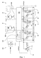
図1は、削岩リグ用の制御システムを示している。複数の消費体、即ち、送りモータ2、回転モータ3及び打撃装置即ちハンマー4が、油圧流体の流体導管を介して、オペレータ制御ベーシック制御システム5(一点鎖線で示す)に接続されている。このベーシック制御システム5は、調整バルブ6,7及び8を備え、これらはオペレータによって制御される。負荷検知タイプのポンプが符号9で示されており、圧力制限バルブが符号10で示されている。
FIG. 1 shows a control system for a rock drilling rig. A plurality of consumers, i.e. a
電子的に制御される補助制御ユニット11が、少なくとも一つの導管を遮断するように、流体導管の中に接続されている。この補助制御ユニット11は、各流体導管への接続のための少なくとも一つの電気制御補助バルブと、消費体2〜4の少なくとも一つの流体パラメータ値を検知するための少なくとも一つのセンサ20を備えている。センサ信号は、信号ケーブル(図示せず)を通して、センサ入力信号is値として補助制御ユニットに送られる。少なくとも一つのパラメータセンサ入力信号入力部を備えた補助制御ユニット内の処理装置12は、前記センサ入力信号is値を受信し、各補助値の信号制御用の少なくとも一つの制御信号を送信する。具体的には、処理装置は、前記センサ入力信号is値を、メモリに記憶されているか、又は瞬時に計算されるパラメータshould値と比較し、比較結果の応答として少なくとも一つの補助値に制御信号を発し、前記少なくとも一つの補助値に関連する流体導管内の流体流を調整するように配置されている。
An electronically controlled
実際には、補助制御ユニットは、動作を最適化する方向に削岩機及び削岩プロセスを制御する方法を提供する自律式プラグインシステムである。 In practice, the auxiliary control unit is an autonomous plug-in system that provides a way to control a rock drill and rock drilling process in a direction that optimizes operation.
独自の特徴は以下に説明され得る。
1.本発明に係るシステムは、主に手動の掘削制御システム又は半手動掘削制御システムへのアドオンシステムであり得る。
2.それは、知的可制御性(intelligent controllability)を有する電子・油圧ハイブリッドシステム(electronics-over-hydraulic hybrid system)である。
3.このシステムは、オリジナル制御システムに最適化機能を付加できる。
4.このシステムは、シーケンス及び時間制御機能を開始し得る。
5.このようなシステムの利点は、通常の手動制御機能性に影響を及ぼすことなく、それを除去したり停止したりできることにある。
6.このシステムは設計がシンプルであり、多数の機能性によって簡単に設計される。
7.この機能は、主として、調整バルブから出る実際の油圧フローを遮断することを通して得られる。これにより、掘削制御システムを選択する時に、使用者に多くの柔軟性が与えられる。
8.このシステムは、例えば、センサ及び油圧バルブと組み合わせたマイクロコントローラユニットを通して容易に具体化される。このシステムは、油圧フロー及び圧力を制御するためのアクチュエータとしてのみ油圧コンポーネントを使用する。これにより、システムは、リグコンポーネントの機械的特性、温度変化影響及び製造公差に対する感度が低くなる。
9.このシステムにはハイドロリックロジックが築かれない。代りに、ロジック機能を操作するために処理装置が用いられる。これにより、より少ないコンポーネントで、かつ、標準的なコンポーネントを使うことが可能になる。この油圧及び処理装置能力の組み合わせが、簡単化された油圧システムを可能にし、コンポーネントの低コスト化及び組立時間の低コスト化を可能にする。
The unique features can be explained below.
1. The system according to the present invention can be an add-on system to a mainly manual drilling control system or semi-manual drilling control system.
2. It is an electronics-over-hydraulic hybrid system with intelligent controllability.
3. This system can add optimization functions to the original control system.
4). The system can initiate sequence and time control functions.
5. The advantage of such a system is that it can be removed or stopped without affecting the normal manual control functionality.
6). This system is simple in design and is easily designed with a large number of functionalities.
7). This function is obtained primarily through blocking the actual hydraulic flow exiting the regulating valve. This gives the user a lot of flexibility when selecting a drilling control system.
8). This system is easily implemented, for example, through a microcontroller unit in combination with sensors and hydraulic valves. This system uses hydraulic components only as actuators to control hydraulic flow and pressure. This makes the system less sensitive to rig component mechanical properties, temperature change effects and manufacturing tolerances.
9. There is no hydraulic logic built into this system. Instead, a processing device is used to operate the logic function. This makes it possible to use standard components with fewer components. This combination of hydraulic and processing equipment capabilities allows for a simplified hydraulic system, reducing component costs and assembly time.
さらに本発明に係るシステムは、上記したようにセンサを通して油圧システムパラメータを監視し、システム性能を最適化する方向で流体流を調整する。また、有利には、センサは、エアフロー(フラッシュ)率/圧力を測定するためにも使用される。 In addition, the system according to the present invention monitors hydraulic system parameters through sensors as described above and regulates fluid flow in a direction that optimizes system performance. Advantageously, the sensor is also used to measure airflow (flash) rate / pressure.
図2には、センサ入力S1〜S5及びオペレータ入力I1〜I6を有する処理装置12における電子部品によって補助制御システムが示されている。補助バルブ制御出力信号用の制御出力はV1〜V6で示されている。
FIG. 2 shows an auxiliary control system with electronic components in the
符号13は、バルブ等を備えた補助制御ユニットの「油圧側」を示している。図面には、この場合には、送りフロー調整バルブであるフロー制御バルブ14が一実施例として示されているだけである。
図3は、本質的に公知の種類であるが、本発明に係る補助制御ユニットが搭載された削岩リグを非常に概略的に示している。 FIG. 3 very schematically shows a rock drilling rig which is of a known type in nature but is equipped with an auxiliary control unit according to the invention.
また、ユーザー入力装置も、ユニットにおけるプログラムファンクションを修正するために使用され得る。システムは、送り圧力、送り速度、ハンマー圧力及びポンプ圧力を最適化でき、また、ドリルビット特性、ドリルロッド特性、ロック特性及び要求掘削モードのグループの中の一つ又は複数に関連するユーザー入力データを考慮することもできる。 User input devices can also be used to modify program functions in the unit. The system can optimize feed pressure, feed speed, hammer pressure and pump pressure, and user input data related to one or more of the group of drill bit characteristics, drill rod characteristics, locking characteristics and required drilling modes Can also be considered.
本発明の実施例によれば、様々な掘削オペレーションシーケンスが、抗ジャミング、抗プランジング、抗プラギング、同期スレッディング及びハンマーパワー調整のような機能によって開始され得る。 According to embodiments of the present invention, various drilling operation sequences can be initiated by functions such as anti-jamming, anti-plunging, anti-plugging, synchronous threading and hammer power adjustment.
これらの機能は、粉砕された岩石層を掘削することにより回転トルクレベルが上がる時、高い貫通速度で空洞を掘削することにより空洞が終わった後に悪い影響を及ぼす危険がある時、泥を掘削することでドリルビットの孔をフラッシングする空気や水が詰まり、過度の摩耗や貫通速度がゼロまで低くなる危険にさらされる時にドリルビットがスタックすることを防止する。 These functions excavate mud when the rotational torque level is increased by drilling a crushed rock layer, and when there is a risk of adverse effects after the cavity ends by drilling the cavity with high penetration speed This prevents clogging of the drill bit when it is clogged with air or water that flushes the hole in the drill bit and is at risk of excessive wear and reduced penetration speed to zero.
非常に高い送り力がネジ上に作用することを防止するためにドリルロッドを接続又は外す時に同期スレッディングが使用され、連結部又はロッドの早い故障を防止するようにする。打撃圧力及びハンマーパワーの調整は、コンポーネントの可使時間をのばすために送り力が減少された時に、ハンマーパワーを低減させることを目的としている。具体的には、本発明に係るシステムは、シャンクやドリルスチールの可使時間を拡張することを可能にする。 Synchronous threading is used when connecting or disconnecting the drill rod to prevent very high feed forces from acting on the screw, so as to prevent premature failure of the coupling or rod. The adjustment of the striking pressure and the hammer power is aimed at reducing the hammer power when the feed force is reduced to extend the pot life. In particular, the system according to the invention makes it possible to extend the working life of shanks and drill steel.
送り圧力は回転トルク(回転圧力)に依存し、同時に、これら二つのパラメータの間の関係は、例えば、岩の状態とビットサイズの関数である。ユーザー入力は、この関係を改良するために使用され得る。送り圧力は、また、送り方向にも依存し、それにより、送り圧力は「フィードアップ」でその最大値になる。打撃圧力は送り圧力に依存し、これらの関係も、ユーザーインプットによって変更され得る。 The feed pressure depends on the rotational torque (rotational pressure), and at the same time the relationship between these two parameters is a function of, for example, rock conditions and bit size. User input can be used to improve this relationship. The feed pressure also depends on the feed direction, so that the feed pressure is at its maximum at “feed-up”. The striking pressure depends on the feed pressure and these relationships can also be changed by user input.
本発明の好ましい実施例によれば、補助制御ユニットは、全ての消費体への流体導管内に介在し、たとえコンディションを変更するとしても、パラメータが相互に調整される掘削オペレーションが得られるように、流体フロー及び圧力を調整することによって掘削オペレーション全体を調整する。 According to a preferred embodiment of the invention, the auxiliary control unit is interposed in the fluid conduit to all consumers so that even if the conditions are changed, a drilling operation is obtained in which the parameters are adjusted to each other. Adjust the overall drilling operation by adjusting the fluid flow and pressure.
蓄積されたデータは、実験に基づくデータから導き出された関数に基づく。これらの関数は、センサからの入力及び掘削オペレータからの入力に基づいて各油圧アクチュエータをどの程度調整するべきか(又は、各油圧バルブをどの程度作動するべきか)を決定し得る。 The accumulated data is based on functions derived from experimental data. These functions may determine how much to adjust each hydraulic actuator (or how much to operate each hydraulic valve) based on input from the sensor and input from the drilling operator.
自動モードにオペレータ入力がない時、全ての油圧コンポーネントはニュートラルモードに戻され、そして、マイクロコントローラ(処理装置)内の全ての関数は、システムを完全手動モードに戻すように無効にされる。処理装置が動力を失うか、又は故障した場合にも、システムは、完全手動モードに戻される。従って、オペレータは、手動モードで掘削を継続することができる。システムを介した全ての油圧フローの状態が、ゼロフロー制限及びゼロ圧力リダクションを持つことになる。制御システムの故障の後でさえ手動モードで掘削を継続して終わらせることができるので、これは非常に有利である。これは、従来の公知の制御システムでは不可能であり、類似の故障はリグを完全に停止させる。 When there is no operator input in automatic mode, all hydraulic components are returned to neutral mode, and all functions in the microcontroller (processor) are disabled to return the system to full manual mode. If the processor loses power or fails, the system is returned to full manual mode. Therefore, the operator can continue excavation in the manual mode. All hydraulic flow conditions through the system will have zero flow restriction and zero pressure reduction. This is very advantageous because the drilling can be continued in the manual mode even after a control system failure. This is not possible with conventional known control systems, and similar faults stop the rig completely.
圧力が特定の制限値より上まで上昇したことを回転圧力センサが検知すると、送り圧力及び送りフローは、とりわけ、ビットサイズ及び岩盤コンディションのオペレータ入力に基づいて処理装置によって決められた値まで低減され得る。これは、抗ジャム機能と呼ばれ、ドリルビットが孔の中でスタックし、生産時間を失うことを防止する。 When the rotary pressure sensor detects that the pressure has risen above a certain limit value, the feed pressure and feed flow are reduced to a value determined by the processor based on operator input of bit size and rock condition, among others. obtain. This is called an anti-jam function and prevents the drill bit from getting stuck in the hole and losing production time.
プリセット制限を超えて回転圧力が停止している限り、送り圧力は低減され続け得る。 As long as the rotational pressure is stopped beyond the preset limit, the feed pressure can continue to be reduced.
回転圧力がプリセット制限より高い状態のままになると、送りフローは、最終的には、有利には、逆向きにされ、そして、送り圧力は、潜在的なジャミング状態から解放されるために最大化される。 If the rotational pressure remains above the preset limit, the feed flow is eventually advantageously reversed and the feed pressure is maximized to be released from a potential jamming condition. Is done.
最大送り圧力は、有利には、岩盤コンディション及びビットサイズのオペレータ入力に基づいて制限されることになる。これは、空洞又は非常に柔らかい岩石層を通して掘削を行う時にプランジング状態を回避するために、最大掘削速度を制限するためにある。プランジング状態は、非常に高い速度で空洞を掘削した後にドリルビットが堅い地面にヒットした時に生じる。これは、極端な孔の逸脱、装置の損傷、又はドリルストリングのスタックを引き起こし得る。オペレーションが制御されないと、ビットは簡単にジャミングし得る。 The maximum feed pressure will advantageously be limited based on rock condition and bit size operator input. This is to limit the maximum excavation speed to avoid plunging conditions when drilling through cavities or very soft rock formations. The plunging condition occurs when the drill bit hits hard ground after drilling the cavity at a very high speed. This can cause extreme hole deviation, equipment damage, or drill string stacking. If operation is not controlled, bits can easily jam.
送り力は、ハンマーから岩への衝撃エネルギの効果的な伝達を保証するように、全ての時間でドリルビットを岩に接触した状態に維持するために使用される。必要とされる送り力のレベルは、岩に伝達される衝撃エネルギの一時関数になる。抗ジャミング機能によって、送り圧力が下げられると、ハンマー衝撃パワーは、送り圧力に基づいて同時に低減されることになる。これは、不慣れな衝撃エネルギからのドリルロッド、シャンク及び連結部へのダメージを低減させることになる。 The feed force is used to keep the drill bit in contact with the rock at all times to ensure effective transfer of impact energy from the hammer to the rock. The required feed force level is a temporary function of the impact energy transferred to the rock. If the feed pressure is reduced by the anti-jamming function, the hammer impact power will be reduced simultaneously based on the feed pressure. This will reduce damage to the drill rod, shank and joints from unfamiliar impact energy.
ダンピング圧力に加えて送り圧力が、送り力のためのパラメータとして使用され得る。 The feed pressure in addition to the damping pressure can be used as a parameter for the feed force.
削岩リグの効率を改善し、油圧システムを安定させるために、ポンプ負荷も、好ましくは、このシステムによって制御される。この制御は、掘削システムのモードと掘削パラメータの状況に基づくものである。 In order to improve the efficiency of the rock drilling rig and stabilize the hydraulic system, the pump load is also preferably controlled by this system. This control is based on the mode of the excavation system and the status of the excavation parameters.
効果的な岩石粉砕プロセスを保証し、かつ、ドリルビットのジャミングを防止するため、削岩中に、岩の切り屑を吹き飛ばすために圧縮空気が用いられる。切り屑が直ぐに一掃されないと、ドリルビットが、孔の底に堆積した切り屑に繰り返し衝撃を与えることになる。この第二の粉砕プロセスは、非常に細かい岩粉を生み出し、多くの衝撃エネルギを浪費するだけである。他の大きな影響は、ドリルビットの後ろに堆積した切り屑が、非常に素早くビットにジャミングし、それが孔の中からドリルビット及びスチールを取り出すことを非常に困難にすることにある。泥を掘削しているような時に、ドリルビット内のフラッシング孔が詰まると、エアフローが止められ得る。従って、好ましくは、フローセンシング装置が、フローコンディションを検知するために、エアフローパス中に導入される。エアフローが止められると、処理装置によって信号が送られることになり、それにより送り方向が直ちに反転されることになる。処理装置におけるこの機能は、抗プラギングと呼ばれる。 Compressed air is used to blow rock chips during rock drilling to ensure an effective rock grinding process and to prevent jamming of the drill bit. If the chips are not cleared immediately, the drill bit will repeatedly impact the chips deposited at the bottom of the hole. This second grinding process produces very fine rock dust and only wastes a lot of impact energy. Another major effect is that chips deposited behind the drill bit jam into the bit very quickly, which makes it very difficult to remove the drill bit and steel from the hole. The airflow can be stopped if the flushing hole in the drill bit is clogged, such as when drilling mud. Therefore, preferably, a flow sensing device is introduced into the air flow path to detect the flow condition. When the air flow is stopped, a signal will be sent by the processing device, which will immediately reverse the feed direction. This function in the processing device is called anti-plugging.
ロッド操作中、ドリルロッドは、ドリルストリング長を延ばしたり縮めたりするために、連結されたり、連結を外されたりすることになる。ドリルロッドは、ネジ付き連結装置を介して連結される。ドリルロッドの回転及びそれらの線形運動は、ネジ部の損傷を防ぐために同期させる必要がある。本発明に係るシステムは、様々な方向に送りフロー及び圧力を調整することによって、ドリル送り及び回転を同期させる機能を有し得る。 During rod operation, the drill rod will be connected and disconnected to extend and shorten the drill string length. The drill rod is connected via a threaded connecting device. The rotation of the drill rods and their linear motion must be synchronized to prevent damage to the thread. The system according to the present invention may have the function of synchronizing drill feed and rotation by adjusting feed flow and pressure in various directions.
また、このシステムは、二重安全保護のために手動調整機能も有し得る。具体的な例としては、ハンマー最小圧力、ハンマー最大圧力及びポンプ最大圧力がある。さらに、何らかの危険な状態を防ぐために安全ロック機能が内蔵される。 The system may also have a manual adjustment function for double safety protection. Specific examples include hammer minimum pressure, hammer maximum pressure, and pump maximum pressure. Furthermore, a safety lock function is built in to prevent any dangerous state.
このシステムは、処理装置やセンサを使用しているので、好ましくは、広範な診断機能を有する。故障状態は、後でダウンロードして分析をするために内部メモリに記憶され得る。 Since this system uses processing equipment and sensors, it preferably has a wide range of diagnostic functions. Fault conditions can be stored in internal memory for later download and analysis.
このシステムが例えば、CAN通信プロトコルを有する場合、それは、他のシステム及びMMI装置とネットワークを結ぶために必要な手段を提供する。また、他の通信手段を想定することもできる。 If this system has, for example, a CAN communication protocol, it provides the necessary means to network with other systems and MMI devices. Also, other communication means can be assumed.
システムが処理装置を有する場合、それは、好ましくは、前記is値とshould値との比較を実行するように設けられた比較回路を有する。 If the system has a processing unit, it preferably has a comparison circuit provided to perform a comparison between the is value and the should value.
好ましくは、システムは、システム動作をオペレータに警告するためのインジケータやスクリーンのようなオペレータディスプレイ及びインターフェイス手段を有する。 Preferably, the system has operator displays and interface means such as indicators and screens to alert the operator of system operation.
本発明に係る削岩機の送りモータ、衝撃装置及び回転モータである消費体への圧力流体供給を制御するための方法では、各消費体用の調整バルブを通して調整弁と各消費体との間の導管内の流体を調整するために以下のステップが実行される。
a.流体導管の少なくとも一つへの接続及び遮断を、少なくとも一つの電気制御式補助バルブを備えた電子制御式補助制御ユニットによって行う。
b.削岩機の少なくとも一つの部材に関する有効流体パラメータ値を、少なくとも一つのセンサで検知する。
c.センサ信号をセンサ入力信号is値として補助制御ユニットに送る。
d.少なくとも一つのパラメータセンサ入力信号入力部を備えた処理装置が、前記センサ入力信号is値を受信し、各補助バルブの信号制御用の少なくとも一つの制御信号を出力する。
e.処理装置によって、前記センサ信号入力is値がパラメータshould値と比較される。
f.少なくとも一つの補助バルブに関する流体導管内の流体フローを調整するために、比較結果に対する応答として前記少なくとも一つの補助バルブに制御信号が出力される。
In the method for controlling the pressure fluid supply to the consumer which is the feed motor, the impact device, and the rotary motor of the rock drill according to the present invention, the regulating valve and each consumer are passed through the regulating valve for each consumer. The following steps are performed to condition the fluid in the conduit.
a. Connection and disconnection to at least one of the fluid conduits is effected by an electronically controlled auxiliary control unit with at least one electrically controlled auxiliary valve.
b. An effective fluid parameter value for at least one member of the rock drill is detected by at least one sensor.
c. The sensor signal is sent to the auxiliary control unit as a sensor input signal is value.
d. A processing device having at least one parameter sensor input signal input unit receives the sensor input signal is value and outputs at least one control signal for signal control of each auxiliary valve.
e. The sensor device compares the sensor signal input is value with a parameter should value.
f. A control signal is output to the at least one auxiliary valve in response to the comparison result to regulate the fluid flow in the fluid conduit with respect to the at least one auxiliary valve.
本発明は、特許請求の範囲の範囲内で改良することができ、特に、本発明に係る方法は、上記にリストアップしたシステムの特徴に対応する別の方法的特徴によって補われ得る。 The invention can be improved within the scope of the claims, in particular the method according to the invention can be supplemented by other method features corresponding to the features of the system listed above.
Claims (13)
前記システムが、各消費体用の調整バルブを有し、
調整バルブと各消費体との間に流体導管が設けられ、
前記システムが、
・流体導管の少なくとも一つの接続及び遮断用の少なくとも一つの電気制御式補助バルブを備えた電子制御式補助制御ユニットと、
・削岩機の少なくとも一つの部材に関する有効流体パラメータ値を感知し、かつ、センサ信号をセンサ入力信号is値として補助制御ユニットに送るための少なくとも一つのセンサと、
・前記センサ入力信号is値を受信するための少なくとも一つのパラメータセンサ入力信号入力部と、各補助バルブの信号制御用の少なくとも一つの制御信号出力部とを有する処理装置と
を備え、
前記処理装置が、前記センサ入力信号is値をパラメータshould値と比較し、比較結果に対する応答として少なくとも一つの補助バルブに制御信号を出力し、前記少なくとも一つの補助バルブに関する流体導管内の流体フローを調整するように構成されている
ことを特徴とする制御システム。 A control system for controlling the supply of pressure fluid to a consumer that is a feed motor, a striking device and a rotary motor of a rock drill,
The system has a regulating valve for each consumer;
A fluid conduit is provided between the regulating valve and each consumer;
The system is
An electronically controlled auxiliary control unit comprising at least one electrically controlled auxiliary valve for connecting and disconnecting the fluid conduit;
At least one sensor for sensing an effective fluid parameter value for at least one member of the rock drill and sending a sensor signal as a sensor input signal is value to the auxiliary control unit;
A processing device having at least one parameter sensor input signal input unit for receiving the sensor input signal is value and at least one control signal output unit for signal control of each auxiliary valve;
The processing device compares the sensor input signal is value with a parameter should value, outputs a control signal to at least one auxiliary valve in response to the comparison result, and determines a fluid flow in a fluid conduit related to the at least one auxiliary valve. A control system characterized by being configured to adjust.
ことを特徴とする請求項1に記載のシステム。 Configured to process one or more fluid parameter values in a group of other parameters consisting of feed motor pressure, impact pressure and rotary motor pressure for the consumer, and flushing air pressure, flushing water pressure and processing equipment The system according to claim 1, wherein:
ことを特徴とする請求項1又は2に記載のシステム。 The system is equipped with user input input means that allow the operator to enter data relating to one or more of the groups of drill bit characteristics, drill rod characteristics, rock characteristics, and required drill modes. The system according to claim 1 or 2.
ことを特徴とする請求項1〜3の何れか一項に記載のシステム。 The system according to any one of claims 1 to 3, characterized in that the auxiliary control system is a plug-in system to adapt to an existing manual system.
ことを特徴とする請求項1〜4の何れか一項に記載のシステム。 The system according to any one of claims 1 to 4, wherein the auxiliary control system comprises at least one sensor from the group of feed pressure sensors, rotational pressure sensors, hammer hammer pressure sensors.
ことを特徴とする請求項1〜5の何れか一項に記載のシステム。 The system according to any one of claims 1 to 5, wherein the auxiliary control system comprises at least one flushing air pressure or flushing water pressure sensor.
ことを特徴とする請求項1〜6の何れか一項に記載のシステム。 The system according to any one of claims 1 to 6, wherein the auxiliary valve has a fluid limiting function and / or a fluid reversing function for each fluid conduit.
前記シーケンスが、抗ジャミング、抗プランジング、抗プラギング、同期されたネジ締め及びハンマーパワー調整の中の一つ又は複数を含み得る
ことを特徴とする請求項1〜7の何れか一項に記載のシステム。 The auxiliary control unit comprises means for initiating a drilling operation sequence according to a specific parameter data level / combination;
8. The sequence of any one of claims 1 to 7, wherein the sequence may include one or more of anti-jamming, anti-plunging, anti-plugging, synchronized screw tightening and hammer power adjustment. System.
送りモータ、打撃装置及び回転モータである消費体への圧力流体供給を制御するために、請求項1〜8の何れか一項に記載のハイドロリック流体制御システムが設けられ、
前記システムが、各消費体用の調整バルブを有し、
前記システムが、調整バルブと各消費体との間を流体導管が繋ぎ、
前記システムが、
・流体導管の少なくとも一つの接続及び遮断用の少なくとも一つの電気制御式補助バルブを備えた電子制御式補助制御ユニットと、
・削岩機の少なくとも一つの部材に関する有効流体パラメータ値を感知し、かつ、センサ信号をセンサ入力信号is値として補助制御ユニットに送るための少なくとも一つのセンサと、
・前記センサ入力信号is値を受信するための少なくとも一つのパラメータセンサ入力信号入力部と、各補助バルブの信号制御用の少なくとも一つの制御信号出力部とを有する処理装置と
を備え、
前記処理装置が、前記センサ入力信号is値をパラメータshould値と比較し、比較結果に対する応答として少なくとも一つの補助バルブに制御信号を出力し、前記少なくとも一つの補助バルブに関する流体導管内の流体フローを調整するように構成されている
ことを特徴とする削岩リグ。 A rock drill rig having a carrier vehicle with a feed beam movably supported by a rock drill,
A hydraulic fluid control system according to any one of claims 1 to 8 is provided to control the supply of pressure fluid to a consumer that is a feed motor, a striking device and a rotary motor.
The system has a regulating valve for each consumer;
The system connects a fluid conduit between the regulating valve and each consumer;
The system is
An electronically controlled auxiliary control unit comprising at least one electrically controlled auxiliary valve for connecting and disconnecting the fluid conduit;
At least one sensor for sensing an effective fluid parameter value for at least one member of the rock drill and sending a sensor signal as a sensor input signal is value to the auxiliary control unit;
A processing device having at least one parameter sensor input signal input unit for receiving the sensor input signal is value and at least one control signal output unit for signal control of each auxiliary valve;
The processing device compares the sensor input signal is value with a parameter should value, outputs a control signal to at least one auxiliary valve in response to the comparison result, and determines a fluid flow in a fluid conduit related to the at least one auxiliary valve. Rock drilling rig, characterized by being configured to adjust.
前記方法が、各消費体用の調整バルブを通して調整バルブと各消費体との間の導管内の流体を調整することを含み、
・少なくとも一つの電気制御式補助バルブを備えた電子制御式補助制御ユニットによって、少なくとも一つの流体導管の接続又は遮断が行われ、
・削岩機の少なくとも一つの部材に関する有効流体パラメータ値が、少なくとも一つのセンサで感知され、かつ、センサ入力信号is値としてセンサ信号が補助制御ユニットに送られ、
・少なくとも一つのパラメータセンサ入力信号入力部を有する処理装置が、前記センサ入力信号is値を受信し、各補助バルブの信号制御用の少なくとも一つの制御信号を出力し、
前記処理装置によって、前記センサ入力信号is値がパラメータshould値と比較され、比較結果に対する応答として少なくとも一つの補助バルブに制御信号が出力され、少なくとも一つの補助バルブに関する流体導管における流体フローが調整される
ことを特徴とする方法。 A method of controlling the supply of pressure fluid to a consumer that is a feed motor, a striking device and a rotary motor of a rock drill,
The method includes regulating fluid in a conduit between the regulating valve and each consumer through a regulating valve for each consumer;
An electronically controlled auxiliary control unit with at least one electrically controlled auxiliary valve connects or disconnects at least one fluid conduit;
An effective fluid parameter value for at least one member of a rock drill is sensed by at least one sensor, and a sensor signal is sent to the auxiliary control unit as a sensor input signal is value;
A processing device having at least one parameter sensor input signal input unit receives the sensor input signal is value and outputs at least one control signal for signal control of each auxiliary valve;
The processor compares the sensor input signal is value with a parameter should value, outputs a control signal to at least one auxiliary valve in response to the comparison result, and adjusts the fluid flow in the fluid conduit for the at least one auxiliary valve. A method characterized by that.
ことを特徴とする請求項10に記載の方法。 One or more fluid parameter values in the group of other parameters consisting of feed motor pressure, impact pressure and rotary motor pressure for the consumer and other parameters consisting of flushing air pressure, flushing water pressure and damping pressure are processed. The method of claim 10.
ことを特徴とする請求項10又は11に記載の方法。 That the system is provided with user input input means that allow the operator to enter data regarding one or more of the groups of drill bit characteristics, drill rod characteristics, rock characteristics, and required drilling modes. 12. A method according to claim 10 or 11, characterized.
前記シーケンスが、抗ジャミング、抗プランジング、抗プラギング、同期されたネジ締め及びハンマーパワー調整の中の一つ又は複数を含み得る
ことを特徴とする請求項10〜12の何れか一項に記載の方法。 The drilling operation sequence is triggered according to the specific parameter data level / combination,
13. The sequence according to any one of claims 10 to 12, wherein the sequence can include one or more of anti-jamming, anti-plunging, anti-plugging, synchronized screw tightening and hammer power adjustment. the method of.
Applications Claiming Priority (3)
| Application Number | Priority Date | Filing Date | Title |
|---|---|---|---|
| USPCT/US2009/003845 | 2009-06-26 | ||
| PCT/US2009/003845 WO2010151242A1 (en) | 2009-06-26 | 2009-06-26 | Control system and rock drill rig |
| PCT/SE2010/000184 WO2010151203A1 (en) | 2009-06-26 | 2010-06-28 | Control system, rock drill rig and control method |
Publications (2)
| Publication Number | Publication Date |
|---|---|
| JP2012531545A JP2012531545A (en) | 2012-12-10 |
| JP5538535B2 true JP5538535B2 (en) | 2014-07-02 |
Family
ID=43386763
Family Applications (1)
| Application Number | Title | Priority Date | Filing Date |
|---|---|---|---|
| JP2012517446A Expired - Fee Related JP5538535B2 (en) | 2009-06-26 | 2010-06-28 | Rock drilling rig control system and control method |
Country Status (7)
| Country | Link |
|---|---|
| US (1) | US8905157B2 (en) |
| EP (1) | EP2446113B8 (en) |
| JP (1) | JP5538535B2 (en) |
| KR (1) | KR101696000B1 (en) |
| CN (1) | CN102498261B (en) |
| AU (1) | AU2010263291B2 (en) |
| WO (2) | WO2010151242A1 (en) |
Families Citing this family (28)
| Publication number | Priority date | Publication date | Assignee | Title |
|---|---|---|---|---|
| CN102561935B (en) * | 2012-01-20 | 2014-02-19 | 中船重工中南装备有限责任公司 | Positioning control system of hydraulic rock drilling machine |
| CN102777165A (en) * | 2012-07-23 | 2012-11-14 | 太仓市旭达机械设备有限公司 | Detection and control device for underreaming bits |
| CN102979499B (en) * | 2012-11-26 | 2015-09-02 | 徐州重型机械有限公司 | Truck-mounted drilling rig operation-control system and method |
| CN102996139B (en) * | 2012-11-30 | 2014-12-17 | 中煤科工集团重庆研究院有限公司 | Hydraulic control system of drill loader |
| CN103206200B (en) * | 2013-03-20 | 2015-12-23 | 湖南有色重型机器有限责任公司 | Automatic control system of rock drill |
| CN103470181B (en) * | 2013-09-23 | 2015-07-08 | 阿特拉斯科普柯(南京)建筑矿山设备有限公司 | Rock drilling device propulsion one-way delay response method and device for realizing method |
| CN103556943B (en) * | 2013-11-08 | 2016-05-11 | 阿特拉斯科普柯(南京)建筑矿山设备有限公司 | According to the method for the ballistic work of feeding force control rock drilling system and device |
| CA2942013C (en) * | 2014-04-18 | 2020-01-14 | Halliburton Energy Services, Inc. | Reaction valve drilling jar system |
| EP3196116A4 (en) * | 2014-08-22 | 2018-05-02 | Daewoo Shipbuilding & Marine Engineering Co., Ltd. | Apparatus and method for controlling and monitoring auxiliary apparatus of drilling equipment in drill ship |
| CN104453845B (en) * | 2014-12-12 | 2017-12-19 | 中国地质大学(武汉) | A kind of full-hydraulic power head drill control system based on CAN |
| US10544656B2 (en) | 2015-04-01 | 2020-01-28 | Schlumberger Technology Corporation | Active fluid containment for mud tanks |
| US20170122092A1 (en) | 2015-11-04 | 2017-05-04 | Schlumberger Technology Corporation | Characterizing responses in a drilling system |
| US11371314B2 (en) | 2017-03-10 | 2022-06-28 | Schlumberger Technology Corporation | Cement mixer and multiple purpose pumper (CMMP) for land rig |
| US10753169B2 (en) | 2017-03-21 | 2020-08-25 | Schlumberger Technology Corporation | Intelligent pressure control devices and methods of use thereof |
| CN107448430B (en) * | 2017-09-19 | 2023-05-30 | 锦州力特液压科技有限公司 | All-hydraulic tunnel drilling machine multi-way reversing valve |
| US11280173B1 (en) | 2018-01-25 | 2022-03-22 | National Technology & Engineering Solutions Of Sandia, Llc | Control systems and methods to enable autonomous drilling |
| US10900343B1 (en) * | 2018-01-25 | 2021-01-26 | National Technology & Engineering Solutions Of Sandia, Llc | Control systems and methods to enable autonomous drilling |
| CN108643825A (en) * | 2018-05-21 | 2018-10-12 | 中国水利水电第十工程局有限公司 | A kind of hydraulic rock drilling machine of tool safety control system |
| CN109339763A (en) * | 2018-11-02 | 2019-02-15 | 湖南五新隧道智能装备股份有限公司 | A kind of full-automatic rock drill and its anti-kelly control method and system |
| US10822944B1 (en) | 2019-04-12 | 2020-11-03 | Schlumberger Technology Corporation | Active drilling mud pressure pulsation dampening |
| US11591897B2 (en) | 2019-07-20 | 2023-02-28 | Caterpillar Global Mining Equipment Llc | Anti-jam control system for mobile drilling machines |
| CN110454140B (en) * | 2019-07-22 | 2022-10-18 | 中煤科工集团西安研究院有限公司 | Drilling machine electro-hydraulic dual-control system with integrated hydraulic linkage valve block and method |
| CN110374578A (en) * | 2019-08-09 | 2019-10-25 | 桂林航天工业学院 | One kind being used for hydraulic impact machine performance testing device |
| CN111648758B (en) * | 2020-06-28 | 2023-07-18 | 青岛科技大学 | Model-free self-adaptive control method and system for well drilling machine propulsion device |
| CN112012974A (en) * | 2020-08-24 | 2020-12-01 | 天水师范学院 | Novel hydraulic synchronous control system for lifting and lowering of oil drilling machine |
| CN112628231B (en) * | 2021-01-29 | 2022-08-02 | 中铁工程装备集团有限公司 | Automatic drilling control valve group, control system and control method thereof |
| CN113153200A (en) * | 2021-04-01 | 2021-07-23 | 湖南创远智能发展有限责任公司 | Hydraulic rock drill electrohydraulic control system and method |
| CN116025330B (en) * | 2022-12-14 | 2023-09-22 | 四川蓝海智能装备制造有限公司 | Electric control type rock drill hydraulic control structure and control method for preventing drill rod from being blocked |
Family Cites Families (25)
| Publication number | Priority date | Publication date | Assignee | Title |
|---|---|---|---|---|
| US3666025A (en) * | 1969-03-20 | 1972-05-30 | Gardner Denver Co | Collaring timing control system for rock drills |
| SE458704B (en) * | 1987-05-18 | 1989-04-24 | Atlas Copco Ab | DEVICE FOR A HYDRAULIC DRIVE SYSTEM CONNECTED TO A LOAD DRIVING HYDRAULIC ENGINE |
| US4854397A (en) * | 1988-09-15 | 1989-08-08 | Amoco Corporation | System for directional drilling and related method of use |
| FI94663C (en) * | 1994-02-28 | 1995-10-10 | Tamrock | Device in a rock drilling control system |
| DK0857249T3 (en) * | 1995-10-23 | 2006-08-14 | Baker Hughes Inc | Drilling facility in closed loop |
| CA2165936C (en) * | 1995-12-21 | 2000-09-26 | Bert Stahl | Method and apparatus for controlling diamond drill feed |
| US5746278A (en) * | 1996-03-13 | 1998-05-05 | Vermeer Manufacturing Company | Apparatus and method for controlling an underground boring machine |
| JPH10306676A (en) * | 1997-04-30 | 1998-11-17 | Furukawa Co Ltd | Automatic rock drill |
| FI981707A0 (en) * | 1998-08-06 | 1998-08-06 | Tamrock Oy | An arrangement for controlling rock drilling |
| DE19941197C2 (en) | 1998-09-23 | 2003-12-04 | Fraunhofer Ges Forschung | Control for a horizontal drilling machine |
| US6637522B2 (en) * | 1998-11-24 | 2003-10-28 | J. H. Fletcher & Co., Inc. | Enhanced computer control of in-situ drilling system |
| US6467557B1 (en) * | 1998-12-18 | 2002-10-22 | Western Well Tool, Inc. | Long reach rotary drilling assembly |
| US6315062B1 (en) | 1999-09-24 | 2001-11-13 | Vermeer Manufacturing Company | Horizontal directional drilling machine employing inertial navigation control system and method |
| SE515204C2 (en) * | 1999-11-03 | 2001-06-25 | Atlas Copco Rock Drills Ab | Method and apparatus for controlling a rock drill |
| US6651755B1 (en) | 2001-03-01 | 2003-11-25 | Vermeer Manufacturing Company | Macro assisted control system and method for a horizontal directional drilling machine |
| FI118134B (en) * | 2001-10-19 | 2007-07-13 | Sandvik Tamrock Oy | Rock drilling device and breaking device |
| US6796381B2 (en) * | 2001-11-12 | 2004-09-28 | Ormexla Usa, Inc. | Apparatus for extraction of oil via underground drilling and production location |
| US7172037B2 (en) | 2003-03-31 | 2007-02-06 | Baker Hughes Incorporated | Real-time drilling optimization based on MWD dynamic measurements |
| US7712309B2 (en) * | 2005-02-17 | 2010-05-11 | Volvo Construction Equipment Ab | Arrangement and a method for controlling a work vehicle |
| FI123639B (en) * | 2005-04-15 | 2013-08-30 | Sandvik Mining & Constr Oy | Method and arrangement for controlling rock drilling |
| FI123636B (en) * | 2006-04-21 | 2013-08-30 | Sandvik Mining & Constr Oy | A method for controlling the operation of a rock drilling machine and a rock drilling machine |
| US7503409B2 (en) * | 2006-04-25 | 2009-03-17 | Schramm, Inc. | Earth drilling rig having electronically controlled air compressor |
| SE530984C2 (en) * | 2007-03-16 | 2008-11-11 | Atlas Copco Rock Drills Ab | Method and apparatus for controlling a rock drill, as well as rock drill and rock drill rig |
| NO329453B1 (en) | 2007-03-16 | 2010-10-25 | Fmc Kongsberg Subsea As | Pressure control device and method |
| DE102007021070B4 (en) * | 2007-05-04 | 2013-10-24 | Fraunhofer-Gesellschaft zur Förderung der angewandten Forschung e.V. | Method for operating a machine tool and machine tool |
-
2009
- 2009-06-26 WO PCT/US2009/003845 patent/WO2010151242A1/en active Application Filing
-
2010
- 2010-06-28 JP JP2012517446A patent/JP5538535B2/en not_active Expired - Fee Related
- 2010-06-28 EP EP10792406.0A patent/EP2446113B8/en not_active Not-in-force
- 2010-06-28 AU AU2010263291A patent/AU2010263291B2/en not_active Ceased
- 2010-06-28 CN CN201080027944.8A patent/CN102498261B/en not_active Expired - Fee Related
- 2010-06-28 KR KR1020117030779A patent/KR101696000B1/en active IP Right Grant
- 2010-06-28 US US13/261,073 patent/US8905157B2/en not_active Expired - Fee Related
- 2010-06-28 WO PCT/SE2010/000184 patent/WO2010151203A1/en active Application Filing
Also Published As
| Publication number | Publication date |
|---|---|
| US8905157B2 (en) | 2014-12-09 |
| KR101696000B1 (en) | 2017-01-13 |
| CN102498261A (en) | 2012-06-13 |
| WO2010151242A1 (en) | 2010-12-29 |
| JP2012531545A (en) | 2012-12-10 |
| EP2446113A1 (en) | 2012-05-02 |
| EP2446113B1 (en) | 2018-01-24 |
| WO2010151203A1 (en) | 2010-12-29 |
| KR20120111941A (en) | 2012-10-11 |
| EP2446113B8 (en) | 2018-03-07 |
| CN102498261B (en) | 2015-01-21 |
| EP2446113A4 (en) | 2016-09-14 |
| US20120085584A1 (en) | 2012-04-12 |
| AU2010263291A1 (en) | 2012-02-02 |
| AU2010263291B2 (en) | 2015-01-22 |
Similar Documents
| Publication | Publication Date | Title |
|---|---|---|
| JP5538535B2 (en) | Rock drilling rig control system and control method | |
| CA2714899C (en) | Anti-stall tool for downhole drilling assemblies | |
| US11118430B2 (en) | Virtual brake system | |
| CA2755165C (en) | Electrical controller for anti-stall tools for downhole drilling assemblies | |
| JP5961580B2 (en) | Drive device for work machine | |
| US7198117B2 (en) | Method and arrangement for controlling percussion rock drilling | |
| WO2015054330A1 (en) | Automated drilling controller including safety logic | |
| JP5393490B2 (en) | Rock drill control method and apparatus and rock drill | |
| CN113153200A (en) | Hydraulic rock drill electrohydraulic control system and method | |
| CN210370482U (en) | Drill jumbo anti-sticking borer system | |
| CN210217604U (en) | Power head operating system of rotary drilling rig and rotary drilling rig | |
| CN117167369A (en) | Rock drill and control system thereof | |
| CN115559953A (en) | Anti-drill-rod-jamming hydraulic oil path structure of rock drill and hydraulic control method | |
| AU2014274506A1 (en) | Eletricial controller for anti-stall tools for downhole drilling assemblies | |
| AU2022244011A1 (en) | Method and system for detecting a loosened joint of a drill string | |
| CN116696314A (en) | Intelligent control system and method based on directional drilling machine |
Legal Events
| Date | Code | Title | Description |
|---|---|---|---|
| A621 | Written request for application examination |
Free format text: JAPANESE INTERMEDIATE CODE: A621 Effective date: 20130514 |
|
| A977 | Report on retrieval |
Free format text: JAPANESE INTERMEDIATE CODE: A971007 Effective date: 20140324 |
|
| TRDD | Decision of grant or rejection written | ||
| A01 | Written decision to grant a patent or to grant a registration (utility model) |
Free format text: JAPANESE INTERMEDIATE CODE: A01 Effective date: 20140402 |
|
| R150 | Certificate of patent or registration of utility model |
Ref document number: 5538535 Country of ref document: JP Free format text: JAPANESE INTERMEDIATE CODE: R150 |
|
| A61 | First payment of annual fees (during grant procedure) |
Free format text: JAPANESE INTERMEDIATE CODE: A61 Effective date: 20140428 |
|
| R250 | Receipt of annual fees |
Free format text: JAPANESE INTERMEDIATE CODE: R250 |
|
| S533 | Written request for registration of change of name |
Free format text: JAPANESE INTERMEDIATE CODE: R313533 |
|
| R350 | Written notification of registration of transfer |
Free format text: JAPANESE INTERMEDIATE CODE: R350 |
|
| R250 | Receipt of annual fees |
Free format text: JAPANESE INTERMEDIATE CODE: R250 |
|
| R250 | Receipt of annual fees |
Free format text: JAPANESE INTERMEDIATE CODE: R250 |
|
| LAPS | Cancellation because of no payment of annual fees |