JP5536410B2 - Inkjet recording device - Google Patents
Inkjet recording device Download PDFInfo
- Publication number
- JP5536410B2 JP5536410B2 JP2009231630A JP2009231630A JP5536410B2 JP 5536410 B2 JP5536410 B2 JP 5536410B2 JP 2009231630 A JP2009231630 A JP 2009231630A JP 2009231630 A JP2009231630 A JP 2009231630A JP 5536410 B2 JP5536410 B2 JP 5536410B2
- Authority
- JP
- Japan
- Prior art keywords
- liquid
- manifold
- ink
- flow path
- supply manifold
- Prior art date
- Legal status (The legal status is an assumption and is not a legal conclusion. Google has not performed a legal analysis and makes no representation as to the accuracy of the status listed.)
- Expired - Fee Related
Links
Images


Classifications
-
- B—PERFORMING OPERATIONS; TRANSPORTING
- B41—PRINTING; LINING MACHINES; TYPEWRITERS; STAMPS
- B41J—TYPEWRITERS; SELECTIVE PRINTING MECHANISMS, i.e. MECHANISMS PRINTING OTHERWISE THAN FROM A FORME; CORRECTION OF TYPOGRAPHICAL ERRORS
- B41J2/00—Typewriters or selective printing mechanisms characterised by the printing or marking process for which they are designed
- B41J2/005—Typewriters or selective printing mechanisms characterised by the printing or marking process for which they are designed characterised by bringing liquid or particles selectively into contact with a printing material
- B41J2/01—Ink jet
- B41J2/17—Ink jet characterised by ink handling
- B41J2/18—Ink recirculation systems
-
- B—PERFORMING OPERATIONS; TRANSPORTING
- B41—PRINTING; LINING MACHINES; TYPEWRITERS; STAMPS
- B41J—TYPEWRITERS; SELECTIVE PRINTING MECHANISMS, i.e. MECHANISMS PRINTING OTHERWISE THAN FROM A FORME; CORRECTION OF TYPOGRAPHICAL ERRORS
- B41J2/00—Typewriters or selective printing mechanisms characterised by the printing or marking process for which they are designed
- B41J2/005—Typewriters or selective printing mechanisms characterised by the printing or marking process for which they are designed characterised by bringing liquid or particles selectively into contact with a printing material
- B41J2/01—Ink jet
- B41J2/135—Nozzles
- B41J2/14—Structure thereof only for on-demand ink jet heads
- B41J2/14201—Structure of print heads with piezoelectric elements
- B41J2/14233—Structure of print heads with piezoelectric elements of film type, deformed by bending and disposed on a diaphragm
-
- B—PERFORMING OPERATIONS; TRANSPORTING
- B41—PRINTING; LINING MACHINES; TYPEWRITERS; STAMPS
- B41J—TYPEWRITERS; SELECTIVE PRINTING MECHANISMS, i.e. MECHANISMS PRINTING OTHERWISE THAN FROM A FORME; CORRECTION OF TYPOGRAPHICAL ERRORS
- B41J2/00—Typewriters or selective printing mechanisms characterised by the printing or marking process for which they are designed
- B41J2/005—Typewriters or selective printing mechanisms characterised by the printing or marking process for which they are designed characterised by bringing liquid or particles selectively into contact with a printing material
- B41J2/01—Ink jet
- B41J2/135—Nozzles
- B41J2/145—Arrangement thereof
- B41J2/155—Arrangement thereof for line printing
-
- B—PERFORMING OPERATIONS; TRANSPORTING
- B41—PRINTING; LINING MACHINES; TYPEWRITERS; STAMPS
- B41J—TYPEWRITERS; SELECTIVE PRINTING MECHANISMS, i.e. MECHANISMS PRINTING OTHERWISE THAN FROM A FORME; CORRECTION OF TYPOGRAPHICAL ERRORS
- B41J2/00—Typewriters or selective printing mechanisms characterised by the printing or marking process for which they are designed
- B41J2/005—Typewriters or selective printing mechanisms characterised by the printing or marking process for which they are designed characterised by bringing liquid or particles selectively into contact with a printing material
- B41J2/01—Ink jet
- B41J2/17—Ink jet characterised by ink handling
- B41J2/19—Ink jet characterised by ink handling for removing air bubbles
-
- B—PERFORMING OPERATIONS; TRANSPORTING
- B41—PRINTING; LINING MACHINES; TYPEWRITERS; STAMPS
- B41J—TYPEWRITERS; SELECTIVE PRINTING MECHANISMS, i.e. MECHANISMS PRINTING OTHERWISE THAN FROM A FORME; CORRECTION OF TYPOGRAPHICAL ERRORS
- B41J2/00—Typewriters or selective printing mechanisms characterised by the printing or marking process for which they are designed
- B41J2/005—Typewriters or selective printing mechanisms characterised by the printing or marking process for which they are designed characterised by bringing liquid or particles selectively into contact with a printing material
- B41J2/01—Ink jet
- B41J2/135—Nozzles
- B41J2/14—Structure thereof only for on-demand ink jet heads
- B41J2002/14459—Matrix arrangement of the pressure chambers
-
- B—PERFORMING OPERATIONS; TRANSPORTING
- B41—PRINTING; LINING MACHINES; TYPEWRITERS; STAMPS
- B41J—TYPEWRITERS; SELECTIVE PRINTING MECHANISMS, i.e. MECHANISMS PRINTING OTHERWISE THAN FROM A FORME; CORRECTION OF TYPOGRAPHICAL ERRORS
- B41J2202/00—Embodiments of or processes related to ink-jet or thermal heads
- B41J2202/01—Embodiments of or processes related to ink-jet heads
- B41J2202/07—Embodiments of or processes related to ink-jet heads dealing with air bubbles
-
- B—PERFORMING OPERATIONS; TRANSPORTING
- B41—PRINTING; LINING MACHINES; TYPEWRITERS; STAMPS
- B41J—TYPEWRITERS; SELECTIVE PRINTING MECHANISMS, i.e. MECHANISMS PRINTING OTHERWISE THAN FROM A FORME; CORRECTION OF TYPOGRAPHICAL ERRORS
- B41J2202/00—Embodiments of or processes related to ink-jet or thermal heads
- B41J2202/01—Embodiments of or processes related to ink-jet heads
- B41J2202/12—Embodiments of or processes related to ink-jet heads with ink circulating through the whole print head
-
- B—PERFORMING OPERATIONS; TRANSPORTING
- B41—PRINTING; LINING MACHINES; TYPEWRITERS; STAMPS
- B41J—TYPEWRITERS; SELECTIVE PRINTING MECHANISMS, i.e. MECHANISMS PRINTING OTHERWISE THAN FROM A FORME; CORRECTION OF TYPOGRAPHICAL ERRORS
- B41J2202/00—Embodiments of or processes related to ink-jet or thermal heads
- B41J2202/01—Embodiments of or processes related to ink-jet heads
- B41J2202/20—Modules
Description
本発明はインクジェット記録装置に係り、特に、複数のヘッドモジュールからなるラインヘッドに対してインクを循環させる技術に関する。 The present invention relates to an ink jet recording apparatus, and more particularly to a technique for circulating ink to a line head composed of a plurality of head modules.
インクジェット記録装置は、複数のノズルが吐出面に配列された記録ヘッド(インクジェットヘッド)を備え、記録媒体と記録ヘッドを相対的に移動させながら、各ノズルからインク滴を吐出させることにより、記録媒体上に画像を記録する。記録ヘッドのインク吐出方式としては、例えば、圧電素子の変位を利用して、圧力室内のインクを加圧してノズルからインク滴を吐出させる圧電方式や、ヒータ等の発熱素子から生じる熱エネルギーを利用して、圧力室内に気泡を発生させ、このとき生じる圧力によってノズルからインク滴を吐出させるサーマル方式などがある。 An ink jet recording apparatus includes a recording head (ink jet head) in which a plurality of nozzles are arranged on an ejection surface, and ejects ink droplets from each nozzle while moving the recording medium and the recording head relatively, thereby recording the recording medium. Record the image on top. As the ink ejection method of the recording head, for example, the piezoelectric method in which the ink in the pressure chamber is pressurized by using the displacement of the piezoelectric element and ink droplets are ejected from the nozzle, or the thermal energy generated from a heating element such as a heater is utilized. Then, there is a thermal method in which bubbles are generated in the pressure chamber and ink droplets are ejected from the nozzles by the pressure generated at this time.
このようなインクジェット記録装置には、シリアル方式とライン方式がある。シリアル方式は、記録媒体の搬送方向に沿ってノズル列が配置された記録ヘッドを備え、記録媒体の幅方向(紙搬送方向と直交する方向;主走査方向)における記録ヘッドの往復移動と記録媒体の搬送を間欠的に繰り返すことで記録を行う方式である。ライン方式は、記録媒体の幅方向に沿ってノズル列が配置された記録ヘッドを備え、記録ヘッドに対して記録媒体を紙搬送方向(副走査方向)に沿って相対移動させるだけで記録を行う方式である。ライン方式は、シリアル方式に比べて記録速度を高速化できるという利点があり、様々な産業分野で幅広く利用されている。 Such an ink jet recording apparatus includes a serial method and a line method. The serial method includes a recording head in which nozzle rows are arranged along the recording medium conveyance direction, and the reciprocating movement of the recording head in the width direction of the recording medium (direction perpendicular to the paper conveyance direction; main scanning direction) and the recording medium. In this method, recording is performed by intermittently repeating the conveyance. The line method includes a recording head in which nozzle rows are arranged along the width direction of the recording medium, and performs recording by simply moving the recording medium relative to the recording head along the paper conveyance direction (sub-scanning direction). It is a method. The line method has an advantage that the recording speed can be increased as compared with the serial method, and is widely used in various industrial fields.
インクジェット記録装置の記録ヘッドについては種々の技術が提案されているが、ライン方式においては、記録媒体の全幅に対応する1つの記録ヘッドをシリコンウェハやガラス等で一体に形成することは、製造方法、歩留まり、発熱、コスト等さまざまな問題があって現実的ではない。そのため、ライン方式では、記録媒体の全幅よりも短尺の記録ヘッド(以下、「ヘッドモジュール」という。)を記録媒体の幅方向に沿って複数並べて配置することによって、記録媒体の全幅に対応する長さを有する長尺のラインヘッドを形成し、記録媒体の全幅に渡る一括記録が行えるようにしている。 Various techniques have been proposed for a recording head of an ink jet recording apparatus. In the line method, it is a manufacturing method that one recording head corresponding to the entire width of a recording medium is integrally formed with a silicon wafer, glass, or the like. There are various problems such as yield, heat generation, and cost, which are not realistic. For this reason, in the line system, a plurality of recording heads (hereinafter referred to as “head modules”) shorter than the entire width of the recording medium are arranged side by side along the width direction of the recording medium, thereby providing a length corresponding to the entire width of the recording medium. A long line head having a height is formed so that batch recording over the entire width of the recording medium can be performed.
ところで、インクジェット記録装置では、記録ヘッド内の液体流路に気泡が存在すると吐出不良等の要因になることから、大気に開放されたタンクと記録ヘッドとの間でインクを循環し、気泡をタンクに回収して大気に放出することが行われている。 By the way, in the ink jet recording apparatus, if bubbles are present in the liquid flow path in the recording head, it becomes a factor such as ejection failure. Therefore, ink is circulated between the tank opened to the atmosphere and the recording head, and the bubbles are stored in the tank. They are collected and released into the atmosphere.
例えば、特許文献1に記載されるインクジェット記録装置では、複数のヘッドモジュールからなるラインヘッドを備え、各ヘッドモジュールのインク循環量のバラツキを抑制するために、複数のヘッドモジュールに対して共通に設けられる主流路とこの主流路から分岐して各ヘッドモジュールへ延びる複数の分岐流路とからなる液体流路を用いて、タンクから各ヘッドモジュールへのインク供給、及び各ヘッドモジュールからタンクへのインク回収(環流)が行われている。 For example, the inkjet recording apparatus described in Patent Document 1 includes a line head composed of a plurality of head modules, and is provided in common for the plurality of head modules in order to suppress variations in the ink circulation amount of each head module. Supply from the tank to each head module, and ink from each head module to the tank using a liquid flow path comprising a main flow path and a plurality of branch flow paths branched from the main flow path and extending to each head module Recovery (perfusion) is taking place.
しかしながら、特許文献1では、主流路と分岐流路との分岐点における気泡の滞留を防止することを課題としているが、大量のインク循環を行うために十分な太さを有するマニホールドを用いた場合の課題については検討されていない。 However, in Patent Document 1, the problem is to prevent bubbles from staying at the branch point between the main flow path and the branch flow path. However, when a manifold having a sufficient thickness is used to circulate a large amount of ink. This issue has not been studied.
本発明はこのような事情に鑑みてなされたもので、複数のヘッドモジュールから構成されるラインヘッドに対し、大量のインク循環を行うために十分に太いマニホールドが用いられる構成において、各ヘッドモジュールへの気泡の到達を防止しつつ、安定したインク循環を実現することができるインクジェット記録装置を提供することを目的とする。 The present invention has been made in view of such circumstances, and in a configuration in which a sufficiently thick manifold is used to circulate a large amount of ink for a line head composed of a plurality of head modules, An object of the present invention is to provide an ink jet recording apparatus capable of realizing stable ink circulation while preventing the arrival of bubbles.
前記目的を達成するために、請求項1に記載の発明は、液体の供給口及び排出口を有する複数の記録ヘッドモジュールと、第1主流路が接続される液体流入口を有し、液体タンクから前記第1主流路を経由して供給される液体が貯留される液体室であって、前記複数の記録ヘッドモジュールの供給口とそれぞれ第1の分岐流路を介して接続される液体供給マニホールドと、第2主流路が接続される液体流出口を有し、前記第2主流路を経由して前記液体タンクに回収される液体が貯留される液体室であって、前記複数の記録ヘッドモジュールの排出口とそれぞれ第2の分岐流路を介して接続される液体回収マニホールドと、前記液体供給マニホールドと前記液体回収マニホールドとの間を接続する第1のバイパス流路と、前記液体供給マニホールド、前記複数の記録ヘッドモジュール、及び前記液体回収マニホールドの順に液体を循環させる液体循環手段と、前記液体供給マニホールドと前記液体回収マニホールドとの間を接続する第2のバイパス流路と、を備え、前記インク供給マニホールド及び前記インク回収マニホールドはそれぞれ液体中に混入した気体が液体と鉛直方向に分離可能な鉛直方向の高さを有し、前記液体供給マニホールドの前記液体流入口が形成される側とは反対側の端部の鉛直方向上側に前記第1のバイパス流路の一端が接続され、前記第2のバイパス流路の一端は前記液体供給マニホールドの前記液体流入口が形成される側とは反対側の端部の鉛直方向下側に接続されると共に、該第2のバイパス流路の他端は前記液体回収マニホールドの前記液体流出口が形成される側とは反対側の端部の鉛直方向下側に接続されることを特徴とするインクジェット記録装置を提供する。 In order to achieve the above object, the invention described in claim 1 includes a plurality of recording head modules having a liquid supply port and a liquid discharge port, a liquid inflow port to which the first main channel is connected, and a liquid tank. A liquid chamber that stores liquid supplied from the first main flow path through the first main flow path, and is connected to the supply ports of the plurality of recording head modules via the first branch flow paths, respectively. And a liquid chamber having a liquid outlet connected to the second main flow path, in which the liquid recovered in the liquid tank via the second main flow path is stored, and the plurality of recording head modules A liquid recovery manifold connected to each of the discharge outlets via a second branch flow path, a first bypass flow path connecting between the liquid supply manifold and the liquid recovery manifold, and the liquid supply manifold Includes field, said plurality of recording head modules, and a liquid circulation means for circulating the liquid in the order of the liquid collection manifold, and a second bypass flow passage which connects between the liquid collection manifold to the liquid supply manifold The ink supply manifold and the ink recovery manifold each have a vertical height at which gas mixed in the liquid can be separated from the liquid in the vertical direction, and the liquid inlet side of the liquid supply manifold is formed. One end of the first bypass flow path is connected to the upper side in the vertical direction of the end opposite to the first end, and one end of the second bypass flow path is on the side where the liquid inlet of the liquid supply manifold is formed. Is connected to the lower side in the vertical direction of the opposite end, and the other end of the second bypass channel is the liquid outlet of the liquid recovery manifold The side to be formed to provide an ink jet recording apparatus characterized Rukoto connected to vertically lower end opposite.
請求項1に記載の発明によれば、液体供給マニホールド及び液体回収マニホールドはそれぞれ液体中に混入した気体が液体と鉛直方向に分離可能な鉛直方向の高さを有し、これらのマニホールド間を接続する第1のバイパス流路が設けられ、該第1のバイパス流路の一端は液体供給マニホールドの液体流入口が形成される側とは反対側の端部の鉛直方向上側(好ましくは上端面)に接続される。これにより、液体供給マニホールドの液体流入口から混入した気泡は、液体の流れに沿って第1のバイパス流路が接続される側に集められ、記録ヘッドモジュールを経由することなく、第1のバイパス流路を通って液体回収マニホールドに送られ、液体流出口から外部に排出される。また、各マニホールドは十分な太さ(内部流路断面積)を有するのでマニホールド内の圧力損失が少なく、各記録ヘッドモジュール間の圧力差を低減することができる。
特に本発明では、第2のバイパス流路を介して液体供給マニホールド内の液体が液体回収マニホールドに流れることにより、液体供給マニホールド内の液体流入口が形成される側と反対側の端部付近の液体の流速が一定値以上に保たれ、端部付近の液体の周辺空気との熱交換による温度変化が抑制され、各ヘッドモジュール間での液体温度差を低減できる。また、第2のバイパス流路によって各マニホールドの鉛直方向下側(好ましくは下端面)同士を接続することによって、第2のバイパス流路への気泡混入を防ぐことができ、流量の安定した循環を行うことができる。
According to the first aspect of the present invention, each of the liquid supply manifold and the liquid recovery manifold has a vertical height at which gas mixed in the liquid can be separated from the liquid in the vertical direction, and the manifolds are connected to each other. A first bypass flow path is provided, and one end of the first bypass flow path is vertically upward (preferably the upper end surface) of the end of the liquid supply manifold opposite to the side where the liquid inlet is formed. Connected to. As a result, the bubbles mixed from the liquid inlet of the liquid supply manifold are collected along the liquid flow to the side to which the first bypass flow path is connected, and the first bypass is not passed through the recording head module. It is sent to the liquid recovery manifold through the flow path and discharged to the outside from the liquid outlet. Further, since each manifold has a sufficient thickness (internal channel cross-sectional area), the pressure loss in the manifold is small, and the pressure difference between the recording head modules can be reduced.
In particular, in the present invention, the liquid in the liquid supply manifold flows to the liquid recovery manifold via the second bypass flow path, so that the vicinity of the end on the side opposite to the side on which the liquid inlet in the liquid supply manifold is formed. The flow rate of the liquid is maintained at a certain value or more, temperature change due to heat exchange with the ambient air of the liquid near the end is suppressed, and the liquid temperature difference between the head modules can be reduced. In addition, by connecting the lower side (preferably the lower end surface) of each manifold in the vertical direction with the second bypass channel, bubbles can be prevented from being mixed into the second bypass channel, and circulation with a stable flow rate can be achieved. It can be performed.
請求項2に記載の発明は、請求項1に記載のインクジェット記録装置において、前記液体供給マニホールドの内部圧力を検出する第1の圧力検出手段と、前記液体回収マニホールドの内部圧力を検出する第2の圧力検出手段と、を備え、前記液体循環手段は、前記第1及び第2の圧力検出手段によって検出された圧力値に基づいて、前記液体供給マニホールド及び前記液体回収マニホールドの内部を所定圧力にそれぞれ調整する圧力調整手段であることを特徴とする。 According to a second aspect of the present invention, in the ink jet recording apparatus according to the first aspect, the first pressure detecting means for detecting the internal pressure of the liquid supply manifold and the second of detecting the internal pressure of the liquid recovery manifold. Pressure detecting means, and the liquid circulating means sets the interior of the liquid supply manifold and the liquid recovery manifold to a predetermined pressure based on the pressure values detected by the first and second pressure detecting means. It is characterized by being a pressure adjusting means for adjusting each .
請求項2に記載の発明によれば、ヘッドモジュールに最も近い共通流路であるマニホールド内に圧力検出手段が存在することにより、大量のインク循環を高精度に実現することが可能となる(マニホールドよりもヘッドモジュールに近い位置では液体流路が分岐されているので、各ヘッドモジュールの影響を受けラインヘッド全体としての圧力を測定することは困難である。)。 According to the second aspect of the present invention, the presence of the pressure detection means in the manifold, which is the common flow path closest to the head module, makes it possible to realize a large amount of ink circulation with high accuracy (manifold). Since the liquid flow path is branched at a position closer to the head module, it is difficult to measure the pressure of the entire line head under the influence of each head module.
請求項3に記載の発明は、請求項2に記載のインクジェット記録装置において、前記第1の圧力検出手段は、前記液体供給マニホールドの前記液体流入口が形成される側とは反対側の端部に配置されると共に、前記第2の圧力検出手段は、前記液体回収マニホールドの前記液体流出口が形成される側とは反対側の端部に配置されることを特徴とする。 According to a third aspect of the present invention, in the ink jet recording apparatus according to the second aspect , the first pressure detecting means is an end of the liquid supply manifold opposite to the side on which the liquid inlet is formed. And the second pressure detecting means is arranged at an end of the liquid recovery manifold opposite to the side where the liquid outlet is formed .
請求項3に記載の発明によれば、マニホールド内で最も流速の遅い部分での圧力が測定されるので、動圧の影響の少ない測定値(圧力値)を得ることができ、より高精度なインク循環を行うことが可能となる。 According to the third aspect of the present invention , since the pressure at the slowest flow velocity in the manifold is measured, it is possible to obtain a measurement value (pressure value) that is less affected by dynamic pressure, and with higher accuracy. Ink circulation can be performed.
請求項4に記載の発明は、液体の供給口及び排出口を有する複数の記録ヘッドモジュールと、第1主流路が接続される液体流入口を有し、液体タンクから前記第1主流路を経由して供給される液体が貯留される液体室であって、前記複数の記録ヘッドモジュールの供給口とそれぞれ第1の分岐流路を介して接続される液体供給マニホールドと、第2主流路が接続される液体流出口を有し、前記第2主流路を経由して前記液体タンクに回収される液体が貯留される液体室であって、前記複数の記録ヘッドモジュールの排出口とそれぞれ第2の分岐流路を介して接続される液体回収マニホールドと、前記液体供給マニホールドと前記液体回収マニホールドとの間を接続する第1のバイパス流路と、前記液体供給マニホールド、前記複数の記録ヘッドモジュール、及び前記液体回収マニホールドの順に液体を循環させる液体循環手段と、前記液体供給マニホールドの内部圧力を検出する第1の圧力検出手段と、前記液体回収マニホールドの内部圧力を検出する第2の圧力検出手段と、を備え、前記液体供給マニホールド及び前記液体回収マニホールドはそれぞれ液体中に混入した気体が液体と鉛直方向に分離可能な鉛直方向の高さを有し、前記液体供給マニホールドの前記液体流入口が形成される側とは反対側の端部の鉛直方向上側に前記第1のバイパス流路の一端が接続され、前記液体循環手段は、前記第1及び第2の圧力検出手段によって検出された圧力値に基づいて、前記液体供給マニホールド及び前記液体回収マニホールドの内部を所定圧力にそれぞれ調整する圧力調整手段であり、前記第1の圧力検出手段は、前記液体供給マニホールドの前記液体流入口が形成される側とは反対側の端部に配置されると共に、前記第2の圧力検出手段は、前記液体回収マニホールドの前記液体流出口が形成される側とは反対側の端部に配置されることを特徴とするインクジェット記録装置を提供する。 According to a fourth aspect of the present invention, the recording head module includes a plurality of recording head modules each having a liquid supply port and a liquid discharge port, and a liquid inflow port to which the first main channel is connected. A liquid chamber in which the liquid to be supplied is stored, the liquid supply manifold connected to the supply ports of the plurality of recording head modules via the first branch flow path, and the second main flow path connected to each other A liquid chamber in which liquid recovered in the liquid tank via the second main flow path is stored, and the discharge ports of the plurality of recording head modules are respectively connected to the second outlets. A liquid recovery manifold connected via a branch flow path; a first bypass flow path connecting the liquid supply manifold and the liquid recovery manifold; the liquid supply manifold; and the plurality of recording heads. A liquid circulating means for circulating the liquid in the order of the module and the liquid recovery manifold; a first pressure detecting means for detecting an internal pressure of the liquid supply manifold; and a second pressure for detecting the internal pressure of the liquid recovery manifold. Detecting means, and each of the liquid supply manifold and the liquid recovery manifold has a vertical height at which gas mixed in the liquid can be separated from the liquid in the vertical direction, and the liquid flow of the liquid supply manifold One end of the first bypass flow path is connected to the upper side in the vertical direction of the end opposite to the side where the inlet is formed, and the liquid circulation means is detected by the first and second pressure detection means. Pressure adjusting means for adjusting the interiors of the liquid supply manifold and the liquid recovery manifold to predetermined pressures based on the pressure values. The first pressure detection means is disposed at the end of the liquid supply manifold opposite to the side on which the liquid inlet is formed, and the second pressure detection means is provided on the liquid recovery manifold. An ink jet recording apparatus is provided, wherein the ink jet recording apparatus is disposed at an end opposite to a side where the liquid outlet is formed.
請求項4に記載の発明によれば、液体供給マニホールド及び液体回収マニホールドはそれぞれ液体中に混入した気体が液体と鉛直方向に分離可能な鉛直方向の高さを有し、これらのマニホールド間を接続する第1のバイパス流路が設けられ、該第1のバイパス流路の一端は液体供給マニホールドの液体流入口が形成される側とは反対側の端部の鉛直方向上側(好ましくは上端面)に接続される。これにより、液体供給マニホールドの液体流入口から混入した気泡は、液体の流れに沿って第1のバイパス流路が接続される側に集められ、記録ヘッドモジュールを経由することなく、第1のバイパス流路を通って液体回収マニホールドに送られ、液体流出口から外部に排出される。また、各マニホールドは十分な太さ(内部流路断面積)を有するのでマニホールド内の圧力損失が少なく、各記録ヘッドモジュール間の圧力差を低減することができる。
特に本発明では、ヘッドモジュールに最も近い共通流路であるマニホールド内に圧力検出手段が存在することにより、大量のインク循環を高精度に実現することが可能となる(マニホールドよりもヘッドモジュールに近い位置では液体流路が分岐されているので、各ヘッドモジュールの影響を受けラインヘッド全体としての圧力を測定することは困難である。)。さらに、マニホールド内で最も流速の遅い部分での圧力が測定されるので、動圧の影響の少ない測定値(圧力値)を得ることができ、より高精度なインク循環を行うことが可能となる。
According to the fourth aspect of the present invention, the liquid supply manifold and the liquid recovery manifold have vertical heights at which the gas mixed in the liquid can be separated from the liquid in the vertical direction, and the manifolds are connected to each other. A first bypass flow path is provided, and one end of the first bypass flow path is vertically upward (preferably the upper end surface) of the end of the liquid supply manifold opposite to the side where the liquid inlet is formed. Connected to. As a result, the bubbles mixed from the liquid inlet of the liquid supply manifold are collected along the liquid flow to the side to which the first bypass flow path is connected, and the first bypass is not passed through the recording head module. It is sent to the liquid recovery manifold through the flow path and discharged to the outside from the liquid outlet. Further, since each manifold has a sufficient thickness (internal channel cross-sectional area), the pressure loss in the manifold is small, and the pressure difference between the recording head modules can be reduced.
In particular, in the present invention, the presence of the pressure detection means in the manifold, which is the common flow path closest to the head module, makes it possible to realize a large amount of ink circulation with high accuracy (closer to the head module than the manifold). Since the liquid flow path is branched at the position, it is difficult to measure the pressure of the entire line head under the influence of each head module. Furthermore, since the pressure at the slowest flow rate in the manifold is measured, it is possible to obtain a measurement value (pressure value) that is less affected by dynamic pressure and to perform more accurate ink circulation. .
請求項5に記載の発明は、請求項1乃至4のいずれか1項に記載のインクジェット記録装置において、前記液体回収マニホールドの前記液体流出口が形成される側とは反対側の端部の鉛直方向下側に前記第1のバイパス流路の他端が接続されることを特徴とする。 According to a fifth aspect of the present invention, in the ink jet recording apparatus according to any one of the first to fourth aspects, the vertical portion of the end of the liquid recovery manifold opposite to the side where the liquid outlet is formed. The other end of the first bypass channel is connected to the lower side in the direction .
請求項5に記載の発明によれば、液体回収マニホールドに排出された気泡が第1バイパス流路と液体回収マニホールドとの接続部付近に滞留することがなく液体供給マニホールドから液体回収マニホールドへの気泡排出性が向上する。 According to the fifth aspect of the present invention, the bubbles discharged from the liquid recovery manifold do not stay near the connection portion between the first bypass flow path and the liquid recovery manifold, and the bubbles from the liquid supply manifold to the liquid recovery manifold Emission is improved.
請求項6に記載の発明は、請求項1乃至5のいずれか1項に記載のインクジェット記録装置において、前記液体流入口は前記液体供給マニホールドの鉛直方向下側に配置されることを特徴とする。 According to a sixth aspect of the present invention, in the ink jet recording apparatus according to any one of the first to fifth aspects, the liquid inlet is disposed on the lower side in the vertical direction of the liquid supply manifold. .
請求項6に記載の発明によれば、気泡の存在しない液体供給マニホールドの鉛直方向下側に液体流入口が配置されるので、気泡の影響のない安定した液体流量を得ることができる。 According to the sixth aspect of the present invention, since the liquid inflow port is arranged on the lower side in the vertical direction of the liquid supply manifold where no bubbles are present, a stable liquid flow rate without the influence of bubbles can be obtained.
請求項7に記載の発明は、請求項1乃至6のいずれか1項に記載のインクジェット記録装置において、前記液体流出口は前記液体回収マニホールドの鉛直方向上側に配置されることを特徴とする。 According to a seventh aspect of the present invention, in the ink jet recording apparatus according to any one of the first to sixth aspects, the liquid outlet is disposed above the liquid recovery manifold in the vertical direction .
請求項7に記載の発明によれば、液体回収マニホールド内の気泡が集まりやすい位置に液体流出口が配置されるので、気泡の排出性が向上する。 According to the seventh aspect of the present invention, the liquid outlet is arranged at a position where the bubbles in the liquid recovery manifold are likely to gather, so that the bubble discharge performance is improved.
請求項8に記載の発明は、請求項1乃至7のいずれか1項に記載のインクジェット記録装置において、前記第1のバイパス流路に配置された開閉弁と、前記開閉弁の開閉動作を制御する弁制御手段と、を備え、前記弁制御手段は、気泡排出制御時には前記開閉弁を開状態にして前記液体供給マニホールド及び前記液体回収マニホールドを前記第1のバイパス流路を介して連通した状態にすることを特徴とする。
The invention according to
請求項8に記載の発明によれば、気泡排出制御時には開閉弁を開状態にして液体供給マニホールドと液体回収マニホールドとの間を第1のバイパス流路を介して連通した状態にし、それ以外の時には開閉弁を開状態にして液体供給マニホールドと液体回収マニホールドとの間は第1のバイパス流路経由では非連通状態とする。これによって、不定期な気泡移動、液体移動による液体循環量の変動を抑えることができる。 According to the eighth aspect of the present invention, at the time of bubble discharge control, the open / close valve is opened so that the liquid supply manifold and the liquid recovery manifold communicate with each other via the first bypass flow path. Sometimes the on-off valve is opened and the liquid supply manifold and the liquid recovery manifold are not connected via the first bypass flow path. As a result, fluctuations in the amount of liquid circulation due to irregular bubble movement and liquid movement can be suppressed.
請求項9に記載の発明は、請求項1乃至8のいずれか1項に記載のインクジェット記録装置において、前記液体供給マニホールドの外周面には断熱材が設けられることを特徴とする。 According to a ninth aspect of the present invention, in the ink jet recording apparatus according to any one of the first to eighth aspects, a heat insulating material is provided on an outer peripheral surface of the liquid supply manifold .
請求項9に記載の発明によれば、液体供給マニホールドと周辺空気との熱交換を減少させることにより、液体供給マニホールド内の液体流入口に近い位置に接続されるヘッドモジュールと離れた位置に接続されるヘッドモジュールとの間の温度差が低減し、ヘッドモジュール間の温度差をより低減することができる。 According to the ninth aspect of the present invention, by reducing heat exchange between the liquid supply manifold and the ambient air, the head module connected to a position close to the liquid inlet in the liquid supply manifold is connected to a position away from the head module. The temperature difference between the head modules is reduced, and the temperature difference between the head modules can be further reduced.
請求項10に記載の発明は、請求項1乃至9のいずれか1項に記載のインクジェット記録装置において、前記液体回収マニホールドの外周面には断熱材が設けられることを特徴とする。
The invention of
請求項10に記載の発明によれば、液体供給マニホールドだけでなく液体回収マニホールドの外周面にも断熱材を設けることによって、周辺空気の影響を受けずに液体循環をより安定した形で実現することが可能となる。
According to the tenth aspect of the present invention, by providing the heat insulating material not only on the liquid supply manifold but also on the outer peripheral surface of the liquid recovery manifold, liquid circulation can be realized in a more stable manner without being influenced by the surrounding air. It becomes possible.
本発明によれば、液体供給マニホールド及び液体回収マニホールドはそれぞれ液体中に混入した気体が液体と鉛直方向に分離可能な鉛直方向の高さを有し、これらのマニホールド間を接続する第1のバイパス流路が設けられ、該第1のバイパス流路の一端は液体供給マニホールドの液体流入口が形成される側とは反対側の端部の鉛直方向上側(好ましくは上端面)に接続される。これにより、液体供給マニホールドの液体流入口から混入した気泡は、液体の流れに沿って第1のバイパス流路が接続される側に集められ、記録ヘッドモジュールを経由することなく、第1のバイパス流路を通って液体回収マニホールドに送られ、液体流出口から外部に排出される。また、各マニホールドは十分な太さ(内部流路断面積)を有するのでマニホールド内の圧力損失が少なく、各記録ヘッドモジュール間の圧力差を低減することができる。 According to the present invention, each of the liquid supply manifold and the liquid recovery manifold has a vertical height at which the gas mixed in the liquid can be separated from the liquid in the vertical direction, and the first bypass connecting the manifolds. A flow path is provided, and one end of the first bypass flow path is connected to the upper side in the vertical direction (preferably the upper end surface) of the end of the liquid supply manifold opposite to the side where the liquid inlet is formed. As a result, the bubbles mixed from the liquid inlet of the liquid supply manifold are collected along the liquid flow to the side to which the first bypass flow path is connected, and the first bypass is not passed through the recording head module. It is sent to the liquid recovery manifold through the flow path and discharged to the outside from the liquid outlet. Further, since each manifold has a sufficient thickness (internal channel cross-sectional area), the pressure loss in the manifold is small, and the pressure difference between the recording head modules can be reduced.
以下、添付図面に従って本発明の好ましい実施の形態について詳説する。 Hereinafter, preferred embodiments of the present invention will be described in detail with reference to the accompanying drawings.
〔インクジェット記録装置の全体構成〕
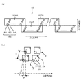
図1は、本発明に係るインクジェット記録装置の一実施形態を示した全体構成図である。同図に示すように、このインクジェット記録装置10は、インクの色毎に設けられた複数の記録ヘッド(以下、単に「ヘッド」ともいう。)12K、12C、12M、12Yを有する印字部12と、各ヘッド12K、12C、12M、12Yに供給するインクを貯蔵しておくインク貯蔵/装填部14と、記録紙16を供給する給紙部18と、記録紙16のカールを除去するデカール処理部20と、前記印字部12のノズル面(インク吐出面)に対向して配置され、記録紙16の平面性を保持しながら記録紙16を搬送する吸着ベルト搬送部22と、印字部12による印字結果を読み取る印字検出部24と、印画済みの記録紙(プリント物)を外部に排紙する排紙部26と、を備えている。
[Overall configuration of inkjet recording apparatus]
FIG. 1 is an overall configuration diagram showing an embodiment of an ink jet recording apparatus according to the present invention. As shown in FIG. 1, the
図1では、給紙部18の一例としてロール紙(連続用紙)のマガジンが示されているが、紙幅や紙質等が異なる複数のマガジンを併設してもよい。また、ロール紙のマガジンに代えて、又はこれと併用して、カット紙が積層装填されたカセットによって用紙を供給してもよい。
In FIG. 1, a magazine for rolled paper (continuous paper) is shown as an example of the
ロール紙を使用する装置構成の場合、図1のように、裁断用のカッター28が設けられており、該カッター28によってロール紙は所望のサイズにカットされる。カッター28は、記録紙16の搬送路幅以上の長さを有する固定刃28Aと、該固定刃28Aに沿って移動する丸刃28Bとから構成されており、印字裏面側に固定刃28Aが設けられ、搬送路を挟んで印字面側に丸刃28Bが配置されている。なお、カット紙を使用する場合には、カッター28は不要である。
In the case of an apparatus configuration using roll paper, a
複数種類の記録紙を利用可能な構成にした場合、紙の種類情報を記録したバーコードあるいは無線タグ等の情報記録体をマガジンに取り付け、その情報記録体の情報を所定の読取装置によって読み取ることで、使用される用紙の種類を自動的に判別し、用紙の種類に応じて適切なインク吐出を実現するようにインク吐出制御を行うことが好ましい。 When multiple types of recording paper are used, an information recording body such as a barcode or wireless tag that records paper type information is attached to the magazine, and the information on the information recording body is read by a predetermined reader. Therefore, it is preferable to automatically determine the type of paper to be used and perform ink ejection control so as to realize appropriate ink ejection according to the type of paper.
給紙部18から送り出される記録紙16はマガジンに装填されていたことによる巻き癖が残り、カールする。このカールを除去するために、デカール処理部20においてマガジンの巻き癖方向と逆方向に加熱ドラム30で記録紙16に熱を与える。このとき、多少印字面が外側に弱いカールとなるように加熱温度を制御するとより好ましい。
The
デカール処理後、カットされた記録紙16は、吸着ベルト搬送部22へと送られる。吸着ベルト搬送部22は、ローラー31、32間に無端状のベルト33が巻き掛けられた構造を有し、少なくとも印字部12のノズル面及び印字検出部24のセンサ面に対向する部分が平面をなすように構成されている。
After the decurling process, the
ベルト33は、記録紙16の幅よりも広い幅寸法を有しており、ベルト面には多数の吸引孔(不図示)が形成されている。図1に示したとおり、ローラー31、32間に掛け渡されたベルト33の内側において印字部12のノズル面及び印字検出部24のセンサ面に対向する位置には吸着チャンバー34が設けられており、この吸着チャンバー34をファン35で吸引して負圧にすることによってベルト33上の記録紙16が吸着保持される。
The
ベルト33が巻かれているローラー31、32の少なくとも一方にモータ(不図示)の動力が伝達されることにより、ベルト33は図1において、時計回り方向に駆動され、ベルト33上に保持された記録紙16は、図1の左から右へと搬送される。
The power of a motor (not shown) is transmitted to at least one of the
縁無しプリント等を印字するとベルト33上にもインクが付着するので、ベルト33の外側の所定位置(印字領域以外の適当な位置)にベルト清掃部36が設けられている。ベルト清掃部36の構成について詳細は図示しないが、例えば、ブラシ・ロール、吸水ロール等をニップする方式、清浄エアーを吹き掛けるエアーブロー方式、あるいはこれらの組み合わせなどがある。清掃用ロールをニップする方式の場合、ベルト線速度とローラー線速度を変えると清掃効果が大きい。
Since ink adheres to the
なお、吸着ベルト搬送部22に代えて、ローラー・ニップ搬送機構を用いる態様も考えられるが、印字領域をローラー・ニップ搬送すると、印字直後に用紙の印字面にローラーが接触するので、画像が滲み易いという問題がある。従って、本例のように、印字領域では画像面と接触させない吸着ベルト搬送が好ましい。
Although a mode using a roller / nip transport mechanism instead of the suction
吸着ベルト搬送部22により形成される用紙搬送路上において印字部12の上流側には、加熱ファン40が設けられている。加熱ファン40は、印字前の記録紙16に加熱空気を吹きつけ、記録紙16を加熱する。印字直前に記録紙16を加熱しておくことにより、インクが着弾後乾き易くなる。
A
印字部12は、最大紙幅に対応する長さを有するライン型ヘッドを紙搬送方向(副走査方向)と直交する方向(主走査方向)に配置した、いわゆるフルライン型のヘッドとなっている。印字部12を構成する各ヘッド12K、12C、12M、12Yは、本インクジェット記録装置10が対象とする最大サイズの記録紙16の少なくとも一辺を超える長さにわたってインク吐出口(ノズル)が複数配列されたライン型ヘッドで構成されている(図2参照)。
The
記録紙16の搬送方向(紙搬送方向)に沿って上流側(図1の左側)から黒(K)、シアン(C)、マゼンタ(M)、イエロー(Y)の順に各色インクに対応したヘッド12K、12C、12M、12Yが配置されている。記録紙16を搬送しつつ各ヘッド12K、12C、12M、12Yからそれぞれ色インクを吐出することにより記録紙16上にカラー画像を形成し得る。
A head corresponding to each color ink in the order of black (K), cyan (C), magenta (M), and yellow (Y) from the upstream side (left side in FIG. 1) along the conveyance direction (paper conveyance direction) of the
このように、紙幅の全域をカバーするフルラインヘッドがインク色毎に設けられてなる印字部12によれば、紙搬送方向(副走査方向)について記録紙16と印字部12を相対的に移動させる動作を一回行うだけで(すなわち、一回の副走査で)記録紙16の全面に画像を記録することができる。これにより、ヘッドが紙搬送方向と直交する方向(主走査方向)に往復動作するシャトル型ヘッドに比べて高速印字が可能であり、生産性を向上させることができる。
Thus, according to the
なお本例では、KCMYの標準色(4色)の構成を例示したが、インク色や色数の組み合わせについては本実施形態には限定されず、必要に応じて淡インク、濃インクを追加してもよい。例えば、ライトシアン、ライトマゼンタ等のライト系インクを吐出するヘッドを追加する構成も可能である。 In this example, the configuration of KCMY standard colors (four colors) is illustrated, but the combination of ink colors and the number of colors is not limited to this embodiment, and light ink and dark ink are added as necessary. May be. For example, it is possible to add a head for ejecting light-colored ink such as light cyan and light magenta.
図1に示したように、インク貯蔵/装填部14は、各ヘッド12K、12C、12M、12Yに対応する色のインクを貯蔵するタンクを有し、各タンクは図示を省略した管路を介して各ヘッド12K、12C、12M、12Yと連通されている。また、インク貯蔵/装填部14は、インク残量が少なくなるとその旨を報知する報知手段(表示手段、警告音発生手段等)を備えるとともに、色間の誤装填を防止するための機構を有している。
As shown in FIG. 1, the ink storage /
印字検出部24は、印字部12の打滴結果を撮像するためのイメージセンサ(ラインセンサ等)を含み、該イメージセンサによって読み取った打滴画像からノズルの目詰まりその他の吐出不良をチェックする手段として機能する。
The
本例の印字検出部24は、少なくとも各ヘッド12K、12C、12M、12Yによるインク吐出幅(画像記録幅)よりも幅の広い受光素子列を有するラインセンサで構成される。このラインセンサは、赤(R)の色フィルタが設けられた光電変換素子(画素)がライン状に配列されたRセンサ列と、緑(G)の色フィルタが設けられたGセンサ列と、青(B)の色フィルタが設けられたBセンサ列とからなる色分解ラインCCDセンサで構成されている。なお、ラインセンサに代えて、受光素子が二次元配列されて成るエリアセンサを用いることも可能である。
The
印字検出部24は、各色のヘッド12K、12C、12M、12Yにより印字されたテストパターンを読み取り、各ヘッドの吐出検出を行う。吐出判定は、吐出の有無、ドットサイズの測定、ドット着弾位置の測定等で構成される。
The
印字検出部24の後段には、後乾燥部42が設けられている。後乾燥部42は、印字された画像面を乾燥させる手段であり、例えば、加熱ファンが用いられる。印字後のインクが乾燥するまでは印字面と接触することは避けたほうが好ましいので、熱風を吹きつける方式が好ましい。
A
後乾燥部42の後段には、加熱・加圧部44が設けられている。加熱・加圧部44は、画像表面の光沢度を制御するための手段であり、画像面を加熱しながら所定の表面凹凸形状を有する加圧ローラー45で加圧し、画像面に凹凸形状を転写する。
A heating /
このようにして生成されたプリント物は、排紙部26から排出される。本来プリントすべき本画像(目的の画像を印刷したもの)とテスト印字とは分けて排出することが好ましい。このインクジェット記録装置10では、本画像のプリント物と、テスト印字のプリント物とを選別してそれぞれの排出部26A、26Bへと送るために排紙経路を切り換える選別手段(不図示)が設けられている。なお、大きめの用紙に本画像とテスト印字とを同時に並列に形成する場合は、カッター(第2のカッター)48によってテスト印字の部分を切り離す。カッター48は、排紙部26の直前に設けられており、画像余白部にテスト印字を行った場合に、本画像とテスト印字部を切断するためのものである。カッター48の構造は前述した第1のカッター28と同様であり、固定刃48Aと丸刃48Bとから構成されている。
The printed matter generated in this manner is outputted from the
また、図示を省略したが、本画像の排出部26Aには、オーダー別に画像を集積するソーターが設けられている。
Although not shown, the
〔ヘッドの構造〕
次に、ヘッド12K、12C、12M、12Yの構造について説明する。なお、各ヘッド12K、12C、12M、12Yの構造は共通しているので、以下では、これらを代表して符号50によってヘッドを示すものとする。
[Head structure]
Next, the structure of the
図3(a)は、ヘッド50の構造例を示す平面透視図であり、図3(b)は、その一部の拡大図である。また、図4は、インク室ユニットの立体的構成を示す断面図(図3(b)中、IV−IV線に沿う断面図)である。
FIG. 3A is a plan perspective view showing a structural example of the
図3(a)に示すように、本例のヘッド50は、複数のノズル51が2次元に配列された複数の短尺のヘッドモジュール100A、100B、…を千鳥状に配列して繋ぎ合わせることにより、記録紙16の全幅に対応する長さのノズル列を有するフルライン型のヘッドモジュールを構成している。なお、各ヘッドモジュール100A、100B、…の構造は共通しているので、以下においては、特に区別しない限り、符号100によって記録ヘッドを示すものとする。
As shown in FIG. 3A, the
各ヘッドモジュール100は、図3(a)、(b)に示すように、インク滴の吐出孔であるノズル51と、各ノズル51に対応する圧力室52等からなる複数のインク室ユニット53を千鳥でマトリクス状に(2次元的に)配置させた構造を有しており、これにより、ヘッド長手方向(紙搬送方向と直交する主走査方向)に沿って並ぶように投影される実質的なノズル間隔(投影ノズルピッチ)の高密度化を達成している。
As shown in FIGS. 3A and 3B, each
なお、本例では短尺のヘッドモジュール100(100A、100B、…)を千鳥状に配列して繋ぎ合わせることでフルライン型のヘッド50を構成しているが、ヘッド50の構成はこれに限定されず、例えば、図示は省略するが、短尺のヘッドモジュールを一列に並べて構成することもできる。
In this example, a short head module 100 (100A, 100B,...) Is arranged in a staggered manner and connected to form a full
各ノズル51に対応して設けられている圧力室52は、図3(b)に示すように、その平面形状が概略正方形状に形成されている。そして、その対角線上の両隅部にノズル51とインク流入口54が設けられている。
As shown in FIG. 3B, the
各圧力室52は、図4に示すように、インク流入口54を介して共通液室55と連通されている。また、各圧力室52に連通するノズル流路60は個別流路62を介して循環共通流路64と連通されている。各ヘッドモジュール100には、供給口66及び排出口68が設けられており、供給口66は共通液室55と連通され、排出口68は循環共通流路64と連通されている。換言すれば、ヘッドモジュール100の供給口66及び排出口68は、ヘッド内部のインク流路(共通液室55、圧力室52、循環共通流路64など)を介して連通されており、後述するように、ヘッドモジュール外部から供給口66に供給されたインクは、ヘッドモジュール内部のインク流路を循環して排出口68からヘッドモジュール外部に排出される構成となっている。
As shown in FIG. 4, each
なお、図4に示すように、ノズル流路60のノズル51近傍に個別流路62が接続される構成が好ましく、ノズル51近傍をインクが循環するようになるので、ノズル51内部のインク増粘が防止され、安定吐出が可能となる。
As shown in FIG. 4, a configuration in which the
圧力室52の天面を構成し共通電極と兼用される振動板56には、個別電極57を備えた圧電素子58が接合されており、個別電極57に駆動電圧を印加することによって圧電素子58が変形してノズル51からインクが吐出される。インクが吐出されると、共通液室55からインク流入口54を通って新しいインクが圧力室52に供給される。
A
本例では、ノズル51から吐出させるインクの吐出力発生手段として圧電素子58を適用したが、圧力室52内にヒータを備え、ヒータの加熱による膜沸騰の圧力を利用してインクを吐出させるサーマル方式を適用することも可能である。
In this example, the
かかる構造を有するインク室ユニット53を図3(b)に示すように、主走査方向に沿う行方向及び主走査方向に対して直交しない一定の角度θを有する斜めの列方向に沿って一定の配列パターンで格子状に多数配列させることにより、本例の高密度ノズルヘッドが実現されている。
As shown in FIG. 3B, the
すなわち、主走査方向に対してある角度θの方向に沿ってインク室ユニット53を一定のピッチdで複数配列する構造により、主走査方向に並ぶように投影されたノズルのピッチPはd× cosθとなり、主走査方向については、各ノズル51が一定のピッチPで直線状に配列されたものと等価的に取り扱うことができる。このような構成により、主走査方向に並ぶように投影されるノズル列が1インチ当たり2400個(2400ノズル/インチ)におよぶ高密度のノズル構成を実現することが可能になる。
That is, with a structure in which a plurality of
なお、本発明の実施に際してノズルの配置構造は、図示の例に限定されず、副走査方向に1列のノズル列を有する配置構造など、様々なノズル配置構造を適用できる。 In implementing the present invention, the nozzle arrangement structure is not limited to the illustrated example, and various nozzle arrangement structures such as an arrangement structure having one nozzle row in the sub-scanning direction can be applied.
〔制御系の構成〕
図5は、インクジェット記録装置10の制御系を示す要部ブロック図である。インクジェット記録装置10は、通信インターフェース70、システムコントローラ72、メモリ74、モータドライバ76、ヒータドライバ78、プリント制御部80、画像バッファメモリ82、ヘッドドライバ84等を備えている。
[Control system configuration]
FIG. 5 is a principal block diagram showing a control system of the
通信インターフェース70は、ホストコンピュータ86から送られてくる画像データを受信するインターフェース部である。通信インターフェース70にはUSB(Universal Serial Bus)、IEEE1394、イーサネット(登録商標)、無線ネットワークなどのシリアルインターフェースやセントロニクスなどのパラレルインターフェースを適用することができる。この部分には、通信を高速化するためのバッファメモリ(不図示)を搭載してもよい。
The
ホストコンピュータ86から送出された画像データは通信インターフェース70を介してインクジェット記録装置10に取り込まれ、一旦メモリ74に記憶される。メモリ74は、通信インターフェース70を介して入力された画像を一旦格納する記憶手段であり、システムコントローラ72を通じてデータの読み書きが行われる。メモリ74は、半導体素子からなるメモリに限らず、ハードディスクなど磁気媒体を用いてもよい。
The image data sent from the
システムコントローラ72は、通信インターフェース70、メモリ74、モータドライバ76、ヒータドライバ78等の各部を制御する制御部である。システムコントローラ72は、中央演算処理装置(CPU)及びその周辺回路等から構成され、ホストコンピュータ86との間の通信制御、メモリ74の読み書き制御等を行うとともに、搬送系のモータ88やヒータ89を制御する制御信号を生成する。
The
メモリ74には、システムコントローラ72のCPUが実行するプログラム及び制御に必要な各種データなどが格納されている。なお、メモリ74は、画像データの一時記憶領域として利用されるとともに、プログラムの展開領域及びCPUの演算作業領域としても利用される。
The
プログラム格納部90には各種制御プログラムが格納されており、システムコントローラ72の指令に応じて、制御プログラムが読み出され、実行される。プログラム格納部90はROMやEEPROMなどの半導体メモリを用いてもよいし、磁気ディスクなどを用いてもよい。外部インターフェースを備え、メモリカードやPCカードを用いてもよい。もちろん、これらの記録媒体のうち、複数の記録媒体を備えてもよい。なお、プログラム格納部90は動作パラメータ等の記録手段(不図示)と兼用してもよい。
Various control programs are stored in the
モータドライバ76は、システムコントローラ72からの指示に従ってモータ88を駆動するドライバ(駆動回路)である。ヒータドライバ78は、システムコントローラ72からの指示に従って後乾燥部42その他各部のヒータ89を駆動するドライバである。
The
ポンプドライバ92は、システムコントローラ72からの指示に従ってポンプ94を駆動するドライバである。図5に示すポンプ94には、インク供給系の各ポンプ124、126が含まれる。
The
プリント制御部80は、システムコントローラ72の制御に従い、メモリ74内の画像データから印字制御用の信号を生成するための各種加工、補正などの処理を行う信号処理機能を有し、生成した印字制御信号(ドットデータ)をヘッドドライバ84に供給する制御部である。プリント制御部80において所要の信号処理が施され、該画像データに基づいてヘッドドライバ84を介してヘッド50のインク滴の吐出量や吐出タイミングの制御が行われる。これにより、所望のドットサイズやドット配置が実現される。
The print control unit 80 has a signal processing function for performing various processing and correction processing for generating a print control signal from image data in the
プリント制御部80には画像バッファメモリ82が備えられており、プリント制御部80における画像データ処理時に画像データやパラメータなどのデータが画像バッファメモリ82に一時的に格納される。なお、図5において画像バッファメモリ82はプリント制御部80に付随する態様で示されているが、メモリ74と兼用することも可能である。また、プリント制御部80とシステムコントローラ72とを統合して1つのプロセッサで構成する態様も可能である。
The print control unit 80 includes an
ヘッドドライバ84は、プリント制御部80から与えられるドットデータに基づいて各色のヘッド50の圧電素子58(図4参照)を駆動するための駆動信号を生成し、圧電素子58に生成した駆動信号を供給する。ヘッドドライバ84にはヘッド50の駆動条件を一定に保つためのフィードバック制御系を含んでいてもよい。
The head driver 84 generates a drive signal for driving the piezoelectric elements 58 (see FIG. 4) of the
印字検出部24は、図1で説明したように、ラインセンサを含むブロックであり、記録紙16に印字された画像を読み取り、所要の信号処理などを行って印字状況(吐出の有無、打滴のばらつきなど)を検出し、その検出結果をプリント制御部80に提供する。
As described with reference to FIG. 1, the
プリント制御部80は、必要に応じて印字検出部24から得られる情報に基づいてヘッド50に対する各種補正を行う。
The print controller 80 performs various corrections on the
〔インク供給系の構成〕
次に、本発明の特徴的部分であるインクジェット記録装置10のインク供給系の構成例(第1〜第6の実施形態)について説明する。
[Configuration of ink supply system]
Next, configuration examples (first to sixth embodiments) of the ink supply system of the ink
<第1の実施形態>
図6は、第1の実施形態に係るインク供給系の構成例を示した模式図である。なお、図6では、説明の便宜上、1色についてのインク供給系のみを示しているが、複数色の場合には同一構成のものが複数備えられる。
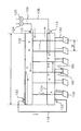
<First Embodiment>
FIG. 6 is a schematic diagram illustrating a configuration example of the ink supply system according to the first embodiment. In FIG. 6, for convenience of explanation, only the ink supply system for one color is shown. However, in the case of a plurality of colors, a plurality of the same configuration is provided.
図6に示すように、本実施形態のインクジェット記録装置10のインク供給系は、主として、インクタンク(不図示)から各ヘッドモジュール100に供給されるインクが一時的に貯留される液体室であるインク供給マニホールド102と、各ヘッドモジュール100からインクタンクに回収されるインクが一時的に貯留される液体室であるインク回収マニホールド104と、を備えて構成される。
As shown in FIG. 6, the ink supply system of the ink
インク供給マニホールド102及びインク回収マニホールド104は、複数のヘッドモジュール100が配列される方向を長手方向とする細長形状であり、インク中に気体が混入した際に気体とインクが上下に分離するのに十分な太さ(内部流路断面積)で構成されている。
The
インクタンクは、各ヘッドモジュール100に供給するためのインクが貯蔵される基タンク(インク供給源)であり、図1に示したインク貯蔵/装填部14に配置されるタンクに相当するものである。インクタンクは大気開放タンクで構成され、第1主流路106を介してインク供給マニホールド102と連通されると共に、第2主流路108を介してインク回収マニホールド104と連通される。第1主流路106には第1液体ポンプ124が接続され、第2主流路108には第2液体ポンプ126が接続される。
The ink tank is a base tank (ink supply source) in which ink to be supplied to each
インク供給マニホールド102の長手方向一端部(図6の右端部)にはインク流入口110が設けられている。このインク流入口110には第1主流路106の一端部(インクタンク側とは反対側の端部)が接続される。また、インク供給マニホールド102から鉛直下方には複数の第1分岐流路112が分岐されており、各第1分岐流路112の先端部はそれぞれ各ヘッドモジュール100の供給口66に接続される。
An
インク回収マニホールド104の長手方向一端部(図6の右端部)にはインク流出口114が設けられている。このインク流出口114には第2主流路108の一端部(インクタンク側とは反対側の端部)が接続される。また、インク回収マニホールド104から鉛直下方には複数の第2分岐流路116が分岐されており、各第2分岐流路116の先端部はそれぞれ各ヘッドモジュール100の排出口68に接続される。
An
かかる構成により、第1液体ポンプ124及び第2液体ポンプ126を作動させると、インクタンクから第1主流路106を経由してインク供給マニホールド102にインクが供給される。そして、インク供給マニホールド102から各第1分岐流路112を通って各ヘッドモジュール100の供給口66からヘッドモジュール内部にインクが分配供給される。ヘッドモジュール内部を循環したインクは、各ヘッドモジュール100の排出口68から各第2分岐流路116を通ってインク回収マニホールド104に回収される。そして、インク回収マニホールド104から第2主流路108を経由してインクタンクにインクが戻される。
With this configuration, when the first
このようなインク循環を実現するために、図5に示したシステムコントローラ72は、駆動回路(ポンプドライバ)92を介して第1液体ポンプ124及び第2液体ポンプ126の駆動を制御することによって、インク供給マニホールド102及びインク回収マニホールド104の内部が所定圧力に保たれるように調整を行っている。
In order to realize such ink circulation, the
具体的には、インク供給マニホールド102の内部圧力がインク回収マニホールド104の内部圧力よりも相対的に高くなるようにマニホールド間に所定の圧力差が設定され、且つ、ヘッドモジュール100内のインクに所定の背圧(負圧)が付与されるように各液体ポンプ124、126の駆動を制御する。
Specifically, a predetermined pressure difference is set between the manifolds so that the internal pressure of the
さらに詳しく説明すると、インク供給マニホールド102の内部圧力をPin、インク回収マニホールド104の内部圧力をPout、ヘッドモジュール100の内部圧力(背圧)をPnzl、インク供給マニホールド102とヘッドモジュール100のノズル面との高低差に基づく圧力差をΔPh1、インク回収マニホールド104とヘッドモジュール100のノズル面との高低差に基づく圧力差をΔPh2としたとき、システムコントローラ72は、次式
Pin+ΔPh1>Pnzl>Pout+ΔPh2 ・・・(1)
を満たすように各液体ポンプ124、126の駆動制御を行う。
More specifically, the internal pressure of the
The drive control of each
このように各液体ポンプ124、126の駆動を制御することによって、ヘッドモジュール100の吐出動作の有無にかかわらず、ヘッドモジュール100内部(特にノズル近傍)で常にインク循環が行われるようにすることができる。これにより、インク増粘等による吐出不良を防止でき、良好な印刷品質を長時間にわたって維持することができる。
By controlling the driving of the liquid pumps 124 and 126 in this way, ink circulation is always performed inside the head module 100 (particularly in the vicinity of the nozzles) regardless of whether or not the
上記の如く構成されるインクジェット記録装置10のインク供給系には、インク供給マニホールド102に混入した気泡の排出性を向上させるために、インク供給マニホールド102とインク回収マニホールド104との間には気泡排出バイパス流路118が設けられている。気泡排出バイパス流路118の一端部はインク供給マニホールド102の接続口(気泡排出口)120に接続され、その他端部はインク回収マニホールド104の接続口(気泡導入口)122に接続される。
In the ink supply system of the ink
インク供給マニホールド102の接続口120は、インク供給マニホールド102の長手方向他端部(インク流入口110が形成される側とは反対側の端部)の鉛直方向上側(好ましくは上端面)に好ましく配置される。インク流入口110からインク供給マニホールド102内に混入した気泡はインクと分離した状態で、インクの流れに沿ってインク供給マニホールド102のインク流入口110が形成される側とは反対側の端部(他端部)の鉛直方向上側に集まりやすい。そこで、インク供給マニホールド102の長手方向他端部の鉛直方向上側に接続口120を配置することにより、インク供給マニホールド102内に混入した気泡を滞留させることなく、気泡排出バイパス流路118からインク回収マニホールド104に容易且つ確実に送出することができる。
The
インク回収マニホールド104の接続口122は、インク回収マニホールド104の長手方向他端部(インク流出口114が形成される側とは反対側の端部)の鉛直方向下側(好ましくは下端面)に好ましく配置される。接続口122が鉛直方向上側に配置されていると、インク回収マニホールド104内に集められた気泡の影響によってインク供給マニホールド102からインク回収マニホールド104の送出が困難となることが懸念される。そこで、インク回収マニホールド104の長手方向他端部の鉛直方向下側に接続口122を配置することにより、インク回収マニホールド104内に存在する気泡の影響を受けることなく、インク供給マニホールド102からインク回収マニホールド104に気泡を容易且つ確実に送出することが可能となる。そして、インク回収マニホールド104に送出された気泡は、インクの流れに沿って反対側の端部(長手方向一端部;図6において右側)に集められ、この位置に設けられるインク流出口114から第2主流路108を経由してインクタンクへ送られて大気放出される。
The
インク回収マニホールド104のインク流出口114は、インク回収マニホールド104の長手方向一端部(図6の右端部)において鉛直方向上側(好ましくは最上部近傍)に好ましく配置される。インク回収マニホールド104内に回収された気泡は鉛直方向上側に集まりやすいため、インク流出口114が鉛直方向下側に配置されていると第2主流路108を経由してインクタンクから大気に放出することができない。そこで、インク流出口114を鉛直方向上側に配置することにより、インク回収マニホールド104内の気泡を第2主流路108を経由してインクタンクから大気に放出することができる。
The
インク供給マニホールド102のインク流入口110は、インク供給マニホールド102の長手方向一端部(図6の右端部)において鉛直方向下側(好ましくは最下部近傍)に好ましく配置される。インク流入口110が鉛直方向上側に配置されていると、インク供給マニホールド102内に混入した気泡の影響を受けて流路抵抗にばらつきが生じ、安定したインク流量を得られなくなることがある。そこで、インク供給マニホールド102の長手方向の一端部の鉛直方向下側にインク流入口110を配置することにより、気泡の影響のない安定したインク流量を得ることができる。
The
本実施形態では、インク供給マニホールド102及びインク回収マニホールド104はいずれもマニホールド長手方向に関して同一の太さで構成されているが、本発明はこれに限定されず、例えば後述する第6の実施形態(図11参照)のように長手方向の一端部から他端部に向かって徐々に太さが変化するように構成されていてもよいし、長手方向の中央部と端部の太さが異なるように構成されていてもよい。ただし、インク流入口110やインク流出口114、各接続口120、122が設けられる位置については気泡排出性を考慮して決定する必要がある。
In this embodiment, the
また本実施形態では、インク供給マニホールド102及びインク回収マニホールド104は、複数のヘッドモジュール100からなるラインヘッド(図6中不図示、図3に符号50で図示)と同等又はそれ以上の長さを有し、複数のヘッドモジュール100が配列される方向(主走査方向)に対して略平行に配置されている。これによって、インク供給マニホールド102及びインク回収マニホールド104から各ヘッドモジュール100に至る分岐流路の流路長がヘッドモジュール間で均一となり、各ヘッドモジュール100に対する圧力損失が均一化され、各ヘッドモジュール100に対するインク循環を安定的に行うことが可能となっている。
In this embodiment, the
また本実施形態では、図6に示したように、鉛直方向下側から上側に向かって、複数のヘッドモジュール100、インク回収マニホールド104、インク供給マニホールド102の順に配置された構成を示したが、これらが配置される順序は特に限定されず、上述したようにインク供給マニホールド102及びインク回収マニホールド104間に所定の圧力差が設定され、インク循環が行われるようになっていればよい。
In the present embodiment, as shown in FIG. 6, a configuration is shown in which a plurality of
また本実施形態では、インク供給マニホールド102及びインク回収マニホールド104はインク中に気体が混入した際に気体とインクが上下に分離するのに十分な太さ(内部流路断面積)を有しているので、各マニホールド102、104内での圧力損失が少なく、複数のヘッドモジュール100間の圧力差を低減することが可能である。また、インク供給マニホールド102及びインク回収マニホールド104に気体が混入しても、その気体は鉛直上方に滞留することになるので鉛直下方に形成される各分岐流路112、116から各ヘッドモジュール100に到達することがない。
In this embodiment, the
(具体例)
以下、第1の実施形態に係るインク供給系の各部の具体例について説明する。
(Concrete example)
Hereinafter, specific examples of each part of the ink supply system according to the first embodiment will be described.
インク供給マニホールド102及びインク回収マニホールド104としては互いに同形状のものが用いられる。マニホールド流路長さLは750mmであり、マニホールド流路断面形状は円形でその直径は14mmである(この直径が十分でないと気液上下分離が起こらない)。また、マニホールド材質としてはポリプロピレンが用いられる。
The
インク供給マニホールド102とインク回収マニホールド104との間に設定される圧力差は4000Paである。
The pressure difference set between the
インク循環流量としては、インク流入口110における流速が9ml/sec、インク流出口114における流速が7ml/secである。
The ink circulation flow rate is 9 ml / sec at the
使用インクは、粘度6mPa・sec、表面張力36mN/m、温度25℃である。 The ink used has a viscosity of 6 mPa · sec, a surface tension of 36 mN / m, and a temperature of 25 ° C.
各マニホールド102、104に接続されるヘッドモジュール100の数は17個であり、各ヘッドモジュール100の配置間隔Mは43mmである。
The number of
気泡排出バイパス流路118は、流路内径4mm、流路長さ300mmである。なお、後述の第3〜第6の実施形態で用いられる循環用バイパス流路132(図8〜図11)は、流路内径2.5mm、流路長さ150mmである。
The bubble
第1主流路106及び第2主流路108は、流路径6mmである。
The first
第1分岐流路112及び第2分岐流路116は、流路径4mmである。
The
なお、各バイパス流路118、132、各分岐流路112、116は気液上下分離が起こらない直径を有するものが用いられる。
The
続いて、上記条件のインクを用いて円筒状内部流路の気液上下分離状態及び分岐流路への気泡流入確認の評価結果について説明する。 Subsequently, the evaluation result of the gas-liquid upper / lower separation state of the cylindrical internal flow path and the bubble inflow confirmation to the branch flow path using the ink of the above conditions will be described.
図12は本評価実験の実験構成を示した図である。同図において、900はパイプ(円筒部材;ポリプロピレンパイプを使用)であり、その内部に円管状内部流路が構成される。また、902は気泡、904は分岐流路パイプ、906はインクタンク、908はチューブポンプ、910はインク受けである。
FIG. 12 is a diagram showing an experimental configuration of this evaluation experiment. In the figure, reference numeral 900 denotes a pipe (cylindrical member; a polypropylene pipe is used), and a circular tubular internal flow path is formed therein.
本評価実験では、図12に示した実験構成を用いて、以下の2項目について評価を行った。
1.気体/液体分離状態
インクで満たされたパイプ900内に意図的に気泡を混入させ、分離状態を目視確認した。
2.分岐流路への気泡流入
各内径(2.5mm,4mm,6mm,8mm,10mm,14mm)のパイプ900に対し、内径4mmの分岐流路パイプ904を43mmピッチで17本溶着した評価用マニホールドを各々作成し、パイプ900内に気泡とインクが混在する状態にして、チューブポンプ908を作動させてインクタンク906からパイプ900に対してインクを9ml/secの流量で流入させ、分岐流路パイプ904への気泡の流入状態を目視確認した。
In this evaluation experiment, the following two items were evaluated using the experimental configuration shown in FIG.
1. Gas / liquid separation state Bubbles were intentionally mixed into the pipe 900 filled with ink, and the separation state was visually confirmed.
2. Bubble inflow into branch flow path An evaluation manifold comprising 17 branch
本実験の評価結果を図13に示す。同図に示すように、パイプ900の流路内径が10mm以上である場合には、パイプ900内で気体と液体が上下に完全分離し、且つ分岐流路パイプ904への気泡の流入もなく、好ましい結果を得られることができた。
The evaluation results of this experiment are shown in FIG. As shown in the figure, when the flow path inner diameter of the pipe 900 is 10 mm or more, the gas and the liquid are completely separated vertically in the pipe 900, and there is no inflow of bubbles into the branch
なお、上述した各マニホールド102、104の直径は14mmであり、本評価実験からも好ましい寸法であることが分かる。 In addition, the diameter of each manifold 102 and 104 mentioned above is 14 mm, and it turns out that it is a preferable dimension also from this evaluation experiment.
<第2の実施形態>
図7は、第2の実施形態に係るインク供給系の構成例を示した模式図である。なお、図7中、図6と共通又は類似する要素には同一の符号を付して説明を省略する。
<Second Embodiment>
FIG. 7 is a schematic diagram illustrating a configuration example of an ink supply system according to the second embodiment. In FIG. 7, elements that are the same as or similar to those in FIG.
第2の実施形態では、図7に示すように、気泡排出バイパス流路118にバルブ(開閉弁)130が設けられている。このバルブ130の開閉動作は、図5に示したシステムコントローラ72によって制御が行われる。
In the second embodiment, as shown in FIG. 7, a valve (open / close valve) 130 is provided in the bubble discharge
システムコントローラ72は、気泡排出制御時にはバルブ130を開状態にして、インク供給マニホールド102とインク回収マニホールド104との間を気泡排出バイパス流路118を介して連通状態にし、インク供給マニホールド102内の気泡を気泡排出バイパス流路118を経由してインク回収マニホールド104に移動させる制御を行う。一方、それ以外の時(気泡排出制御が行われない時)にはバルブ130を閉状態にして、インク供給マニホールド102とインク回収マニホールド104との間を気泡排出バイパス流路118経由では非連通状態にする。
During the bubble discharge control, the
第2の実施形態によれば、不定期な気泡移動によるインク循環流量の変動を抑えることができる。 According to the second embodiment, fluctuations in the ink circulation flow rate due to irregular bubble movement can be suppressed.
<第3の実施形態>
図8は、第3の実施形態に係るインク供給系の構成例を示した模式図である。なお、図8中、図6又は図7と共通又は類似する要素には同一の符号を付して説明を省略する。
<Third Embodiment>
FIG. 8 is a schematic diagram illustrating a configuration example of an ink supply system according to the third embodiment. In FIG. 8, elements that are the same as or similar to those in FIG. 6 or FIG.
前述した各実施形態のようにインク供給マニホールド102及びインク回収マニホールド104が太く構成される場合、マニホールド内のインク流速が遅くなり、周辺空気との熱交換によるインク温度が変化し、ヘッドモジュール100間でインク温度に差が生じることが懸念される。
When the
そこで第3の実施形態では、図8に示すように、インク供給マニホールド102とインク回収マニホールド104との間に気泡排出バイパス流路118とは別の循環用バイパス流路132が設けられている。これにより、各ヘッドモジュール100を経由することなく、インク供給マニホールド102からインク回収マニホールド104に直接インクが循環できるようになっている。
Therefore, in the third embodiment, as shown in FIG. 8, a
循環用バイパス流路132の一端部が接続される接続口(インク排出口)134は、インク供給マニホールド102の長手方向他端部(インク流入口110側とは反対側の端部;図8の左端部)の鉛直方向下側(好ましくは下端面)に好ましく配置される。
The connection port (ink discharge port) 134 to which one end of the circulation
循環用バイパス流路132の他端部が接続される接続口(インク導入口)136は、インク回収マニホールド104の長手方向他端部(インク流出口114側とは反対側の端部;図8の左端部)の鉛直方向下側(好ましくは下端面)に好ましく配置される。
The connection port (ink introduction port) 136 to which the other end of the circulation
第3の実施形態によれば、印刷動作中に循環用バイパス流路132によるインク循環を行うことで、ヘッドモジュール100間でのインク温度差を低減することができる。
According to the third embodiment, the ink temperature difference between the
また、インク供給マニホールド102及びインク回収マニホールド104の鉛直方向下側(好ましくは下端面)に循環用バイパス流路132が接続されるので、循環用バイパス流路132への気泡混入が防止され、流量の安定した循環を行うことができる。
Further, since the circulation
<第4の実施形態>
図9は、第4の実施形態に係るインク供給系の構成例を示した模式図である。なお、図9中、図6〜図8と共通又は類似する要素には同一の符号を付して説明を省略する。
<Fourth Embodiment>
FIG. 9 is a schematic diagram illustrating a configuration example of an ink supply system according to the fourth embodiment. In FIG. 9, elements that are the same as or similar to those in FIGS.
第4の実施形態では、図9に示すように、インク供給マニホールド102及びインク回収マニホールド104の外周面にそれぞれ断熱材140、142が設けられた構成となっている。
In the fourth embodiment, as illustrated in FIG. 9,
第4の実施形態によれば、インク供給マニホールド102の外周面に設けられた断熱材140によって、インク供給マニホールド102と周辺空気との熱交換を減少させることができ、各ヘッドモジュール100間の温度差をより低減することができる。
According to the fourth embodiment, the
また、インク供給マニホールド102だけでなく、インク回収マニホールド104の外周面に断熱材142を設けることによって、周辺空気の影響を受けずにインク循環をより安定した形で実現することが可能となる。
Further, by providing the
<第5の実施形態>
図10は、第5の実施形態に係るインク供給系の構成例を示した模式図である。なお、図10中、図6〜図9と共通又は類似する要素には同一の符号を付して説明を省略する。
<Fifth Embodiment>
FIG. 10 is a schematic diagram illustrating a configuration example of an ink supply system according to the fifth embodiment. In FIG. 10, elements that are the same as or similar to those in FIGS.
第5の実施形態では、図10に示すように、インク供給マニホールド102の長手方向他端部(インク流入口110側とは反対側の端部)に第1圧力センサ144が配置されると共に、インク回収マニホールド104の長手方向他端部(インク流出口114側とは反対側の端部)に第2圧力センサ146が配置された構成となっている。
In the fifth embodiment, as shown in FIG. 10, a
各圧力センサ144、146は、それぞれ対応するマニホールド102、104の内部圧力を検出する圧力検出手段であり、各圧力センサ144、146によって検出された測定値(圧力値)は図5に示したシステムコントローラ72に通知される。
The
システムコントローラ72は、各圧力センサ144、146から通知された測定値に基づいて、各マニホールド102、104の内部圧力が目標圧力となるように、第1液体ポンプ124及び第2液体ポンプ126の駆動を制御する。システムコントローラ72による制御方法については、第1の実施形態と同様であるので説明を省略する。
The
第5の実施形態によれば、インク供給マニホールド102及びインク回収マニホールド104内で最も流速の遅い部分(インク流入口110又はインク流出口114から最も離れたマニホールド端部)の圧力を測定することにより、動圧の影響の少ない測定値を得ることができる。これによって、インク供給マニホールド102及びインク回収マニホールド104の内部圧力をより高精度に制御することが可能となり、インク循環のさらなる安定化を図ることができる。
According to the fifth embodiment, by measuring the pressure of the slowest flow rate portion (the manifold end furthest from the
<第6の実施形態>
図11は、第6の実施形態に係るインク供給系の構成例を示した模式図である。なお、図11中、図6〜図10と共通又は類似する要素には同一の符号を付して説明を省略する。
<Sixth Embodiment>
FIG. 11 is a schematic diagram illustrating a configuration example of an ink supply system according to the sixth embodiment. In FIG. 11, elements that are the same as or similar to those in FIGS.
第6の実施形態では、インク供給マニホールド102及びインク回収マニホールド104の天面(図11において上側の内壁面)が傾斜した構成となっている。
In the sixth embodiment, the top surfaces (upper inner wall surfaces in FIG. 11) of the
インク供給マニホールド102の天面102aは、インク供給マニホールド102の長手方向一端部(インク流入口110側の端部)よりも他端部(接続口120側の端部)の方が鉛直方向上側となるように斜めに傾いた傾斜面で構成されている。これにより、インク供給マニホールド102に混入した気泡は天面102aの傾きに沿って接続口120の周辺部に集まりやすく、気泡排出バイパス流路118からインク回収マニホールド104に容易に送出できるようになっている。
The
また、インク回収マニホールド104の天面104aは、インク回収マニホールド104の長手方向他端部(接続口122側の端部)よりも一端部(インク流出口114側の端部)の方が鉛直方向上側となるように斜めに傾いた傾斜面で構成されている。これにより、インク回収マニホールド104に回収された気泡は天面104aの傾きに沿ってインク流出口114の周辺部に集まりやすく、第2主流路108から容易にインクタンクへ送出することができ、インクタンクで大気に放出されるようになっている。
Further, the
このように第6の実施形態によれば、マニホールド内の気泡の排出性を向上させることができる。 As described above, according to the sixth embodiment, it is possible to improve the discharge performance of the bubbles in the manifold.
なお、第6の実施形態では、インク供給マニホールド102の天面102aやインク回収マニホールド104の天面104aが傾斜面からなる構成(底面に対して天面が斜めに傾いた構成)を一例として示したが、本発明はこれに限らず、第1〜第5の実施形態のインク供給マニホールド102やインク回収マニホールド104のように底面と天面が平行な構成においてマニホールド全体を斜めに傾けるようにしてもよい。この場合もマニホールド内の気泡の排出性を向上させることが可能である。
In the sixth embodiment, a configuration in which the
以上、本発明のインクジェット記録装置について詳細に説明したが、本発明は、以上の例には限定されず、本発明の要旨を逸脱しない範囲において、各種の改良や変形を行ってもよいのはもちろんである。 Although the ink jet recording apparatus of the present invention has been described in detail above, the present invention is not limited to the above examples, and various improvements and modifications may be made without departing from the gist of the present invention. Of course.
10…インクジェット記録装置、50…ヘッド、51…ノズル、52…圧力室、55…共通流路、56…振動板、58…圧電素子、66…供給口、68…排出口、72…システムコントローラ、100…ヘッドモジュール、102…インク供給マニホールド、104…インク回収マニホールド、106…第1主流路、108…第2主流路、110…インク流入口、112…第1分岐流路、114…インク流出口、116…第2分岐流路、118…気泡排出バイパス流路、120、122…接続口、124…第1液体ポンプ、126…第2液体ポンプ、130…バルブ、132…循環用バイパス流路、140、142…断熱材、144、146…圧力センサ
DESCRIPTION OF
Claims (10)
第1主流路が接続される液体流入口を有し、液体タンクから前記第1主流路を経由して供給される液体が貯留される液体室であって、前記複数の記録ヘッドモジュールの供給口とそれぞれ第1の分岐流路を介して接続される液体供給マニホールドと、
第2主流路が接続される液体流出口を有し、前記第2主流路を経由して前記液体タンクに回収される液体が貯留される液体室であって、前記複数の記録ヘッドモジュールの排出口とそれぞれ第2の分岐流路を介して接続される液体回収マニホールドと、
前記液体供給マニホールドと前記液体回収マニホールドとの間を接続する第1のバイパス流路と、
前記液体供給マニホールド、前記複数の記録ヘッドモジュール、及び前記液体回収マニホールドの順に液体を循環させる液体循環手段と、
前記液体供給マニホールドと前記液体回収マニホールドとの間を接続する第2のバイパス流路と、を備え、
前記液体供給マニホールド及び前記液体回収マニホールドはそれぞれ液体中に混入した気体が液体と鉛直方向に分離可能な鉛直方向の高さを有し、
前記液体供給マニホールドの前記液体流入口が形成される側とは反対側の端部の鉛直方向上側に前記第1のバイパス流路の一端が接続され、
前記第2のバイパス流路の一端は前記液体供給マニホールドの前記液体流入口が形成される側とは反対側の端部の鉛直方向下側に接続されると共に、該第2のバイパス流路の他端は前記液体回収マニホールドの前記液体流出口が形成される側とは反対側の端部の鉛直方向下側に接続されることを特徴とするインクジェット記録装置。 A plurality of recording head modules having a liquid supply port and a discharge port;
A liquid chamber having a liquid inflow port to which the first main channel is connected, and storing a liquid supplied from a liquid tank via the first main channel, the supply ports of the plurality of recording head modules; And a liquid supply manifold connected to each other via a first branch flow path,
A liquid chamber having a liquid outlet to which the second main flow path is connected, in which the liquid recovered in the liquid tank via the second main flow path is stored, wherein the plurality of recording head modules are discharged; A liquid recovery manifold connected to the outlet via a second branch channel, respectively.
A first bypass flow path connecting between the liquid supply manifold and the liquid recovery manifold;
Liquid circulation means for circulating liquid in the order of the liquid supply manifold, the plurality of recording head modules, and the liquid recovery manifold;
A second bypass flow path connecting between the liquid supply manifold and the liquid recovery manifold ,
The liquid supply manifold and the liquid recovery manifold each have a vertical height at which gas mixed in the liquid can be separated from the liquid in the vertical direction,
One end of the first bypass channel is connected to the upper side in the vertical direction of the end opposite to the side where the liquid inlet of the liquid supply manifold is formed ,
One end of the second bypass channel is connected to the lower side in the vertical direction of the end of the liquid supply manifold opposite to the side where the liquid inlet is formed, and the second bypass channel an ink jet recording apparatus and the other end, characterized in Rukoto connected to vertically lower the opposite end to the side where the liquid outlet of the liquid collection manifold are formed.
前記液体供給マニホールドの内部圧力を検出する第1の圧力検出手段と、
前記液体回収マニホールドの内部圧力を検出する第2の圧力検出手段と、を備え、
前記液体循環手段は、前記第1及び第2の圧力検出手段によって検出された圧力値に基づいて、前記液体供給マニホールド及び前記液体回収マニホールドの内部を所定圧力にそれぞれ調整する圧力調整手段であることを特徴とするインクジェット記録装置。 The inkjet recording apparatus according to claim 1 , wherein
First pressure detecting means for detecting an internal pressure of the liquid supply manifold;
Second pressure detection means for detecting the internal pressure of the liquid recovery manifold,
The liquid circulating means is a pressure adjusting means for adjusting the insides of the liquid supply manifold and the liquid recovery manifold to predetermined pressures based on the pressure values detected by the first and second pressure detecting means. An ink jet recording apparatus.
前記第1の圧力検出手段は、前記液体供給マニホールドの前記液体流入口が形成される側とは反対側の端部に配置されると共に、前記第2の圧力検出手段は、前記液体回収マニホールドの前記液体流出口が形成される側とは反対側の端部に配置されることを特徴とするインクジェット記録装置。 The inkjet recording apparatus according to claim 2 ,
The first pressure detection means is disposed at an end of the liquid supply manifold opposite to the side on which the liquid inlet is formed, and the second pressure detection means is provided on the liquid recovery manifold. An ink jet recording apparatus, wherein the ink jet recording apparatus is disposed at an end opposite to a side on which the liquid outlet is formed.
第1主流路が接続される液体流入口を有し、液体タンクから前記第1主流路を経由して供給される液体が貯留される液体室であって、前記複数の記録ヘッドモジュールの供給口とそれぞれ第1の分岐流路を介して接続される液体供給マニホールドと、
第2主流路が接続される液体流出口を有し、前記第2主流路を経由して前記液体タンクに回収される液体が貯留される液体室であって、前記複数の記録ヘッドモジュールの排出口とそれぞれ第2の分岐流路を介して接続される液体回収マニホールドと、
前記液体供給マニホールドと前記液体回収マニホールドとの間を接続する第1のバイパス流路と、
前記液体供給マニホールド、前記複数の記録ヘッドモジュール、及び前記液体回収マニホールドの順に液体を循環させる液体循環手段と、
前記液体供給マニホールドの内部圧力を検出する第1の圧力検出手段と、
前記液体回収マニホールドの内部圧力を検出する第2の圧力検出手段と、を備え、
前記液体供給マニホールド及び前記液体回収マニホールドはそれぞれ液体中に混入した気体が液体と鉛直方向に分離可能な鉛直方向の高さを有し、
前記液体供給マニホールドの前記液体流入口が形成される側とは反対側の端部の鉛直方向上側に前記第1のバイパス流路の一端が接続され、
前記液体循環手段は、前記第1及び第2の圧力検出手段によって検出された圧力値に基づいて、前記液体供給マニホールド及び前記液体回収マニホールドの内部を所定圧力にそれぞれ調整する圧力調整手段であり、
前記第1の圧力検出手段は、前記液体供給マニホールドの前記液体流入口が形成される側とは反対側の端部に配置されると共に、前記第2の圧力検出手段は、前記液体回収マニホールドの前記液体流出口が形成される側とは反対側の端部に配置されることを特徴とするインクジェット記録装置。 A plurality of recording head modules having a liquid supply port and a discharge port;
A liquid chamber having a liquid inflow port to which the first main channel is connected, and storing a liquid supplied from a liquid tank via the first main channel, the supply ports of the plurality of recording head modules; And a liquid supply manifold connected to each other via a first branch flow path,
A liquid chamber having a liquid outlet to which the second main flow path is connected, in which the liquid recovered in the liquid tank via the second main flow path is stored, wherein the plurality of recording head modules are discharged; A liquid recovery manifold connected to the outlet via a second branch channel, respectively.
A first bypass flow path connecting between the liquid supply manifold and the liquid recovery manifold;
Liquid circulation means for circulating liquid in the order of the liquid supply manifold, the plurality of recording head modules, and the liquid recovery manifold;
First pressure detecting means for detecting an internal pressure of the liquid supply manifold;
Second pressure detection means for detecting the internal pressure of the liquid recovery manifold ,
The liquid supply manifold and the liquid recovery manifold each have a vertical height at which gas mixed in the liquid can be separated from the liquid in the vertical direction,
One end of the first bypass channel is connected to the upper side in the vertical direction of the end opposite to the side where the liquid inlet of the liquid supply manifold is formed ,
The liquid circulating means is a pressure adjusting means for adjusting the insides of the liquid supply manifold and the liquid recovery manifold to predetermined pressures based on pressure values detected by the first and second pressure detecting means,
The first pressure detection means is disposed at an end of the liquid supply manifold opposite to the side on which the liquid inlet is formed, and the second pressure detection means is provided on the liquid recovery manifold. an ink jet recording apparatus according to claim Rukoto disposed at the end portion opposite to the side where the liquid outlet port is formed.
前記液体回収マニホールドの前記液体流出口が形成される側とは反対側の端部の鉛直方向下側に前記第1のバイパス流路の他端が接続されることを特徴とするインクジェット記録装置。 The inkjet recording apparatus according to any one of claims 1 to 4 ,
An inkjet recording apparatus, wherein the other end of the first bypass flow path is connected to the lower side in the vertical direction of the end of the liquid recovery manifold opposite to the side on which the liquid outlet is formed.
前記液体流入口は前記液体供給マニホールドの鉛直方向下側に配置されることを特徴とするインクジェット記録装置。 The inkjet recording apparatus according to any one of claims 1 to 5 ,
The ink jet recording apparatus according to claim 1, wherein the liquid inflow port is disposed on a lower side in the vertical direction of the liquid supply manifold.
前記液体流出口は前記液体回収マニホールドの鉛直方向上側に配置されることを特徴とするインクジェット記録装置。 The inkjet recording apparatus according to any one of claims 1 to 6 ,
The ink jet recording apparatus according to claim 1, wherein the liquid outlet is disposed on an upper side in the vertical direction of the liquid recovery manifold.
前記第1のバイパス流路に配置された開閉弁と、
前記開閉弁の開閉動作を制御する弁制御手段と、を備え、
前記弁制御手段は、気泡排出制御時には前記開閉弁を開状態にして前記液体供給マニホールド及び前記液体回収マニホールドを前記第1のバイパス流路を介して連通した状態にすることを特徴とするインクジェット記録装置。 The inkjet recording apparatus according to any one of claims 1 to 7 ,
An on-off valve disposed in the first bypass flow path;
Valve control means for controlling the opening and closing operation of the on-off valve, and
In the ink jet recording, the valve control means opens the open / close valve to make the liquid supply manifold and the liquid recovery manifold communicate with each other via the first bypass flow path during bubble discharge control. apparatus.
前記液体供給マニホールドの外周面には断熱材が設けられることを特徴とするインクジェット記録装置。 The inkjet recording apparatus according to any one of claims 1 to 8 ,
An ink jet recording apparatus, wherein a heat insulating material is provided on an outer peripheral surface of the liquid supply manifold.
前記液体回収マニホールドの外周面には断熱材が設けられることを特徴とするインクジェット記録装置。 The inkjet recording apparatus according to any one of claims 1 to 9 ,
An ink jet recording apparatus, wherein a heat insulating material is provided on an outer peripheral surface of the liquid recovery manifold.
Priority Applications (3)
| Application Number | Priority Date | Filing Date | Title |
|---|---|---|---|
| JP2009231630A JP5536410B2 (en) | 2009-10-05 | 2009-10-05 | Inkjet recording device |
| EP10186407.2A EP2305472B1 (en) | 2009-10-05 | 2010-10-04 | Inkjet recording apparatus |
| US12/896,999 US8529039B2 (en) | 2009-10-05 | 2010-10-04 | Inkjet recording apparatus having thick manifolds for large volume circulation of ink |
Applications Claiming Priority (1)
| Application Number | Priority Date | Filing Date | Title |
|---|---|---|---|
| JP2009231630A JP5536410B2 (en) | 2009-10-05 | 2009-10-05 | Inkjet recording device |
Publications (3)
| Publication Number | Publication Date |
|---|---|
| JP2011079169A JP2011079169A (en) | 2011-04-21 |
| JP2011079169A5 JP2011079169A5 (en) | 2012-08-16 |
| JP5536410B2 true JP5536410B2 (en) | 2014-07-02 |
Family
ID=43066598
Family Applications (1)
| Application Number | Title | Priority Date | Filing Date |
|---|---|---|---|
| JP2009231630A Expired - Fee Related JP5536410B2 (en) | 2009-10-05 | 2009-10-05 | Inkjet recording device |
Country Status (3)
| Country | Link |
|---|---|
| US (1) | US8529039B2 (en) |
| EP (1) | EP2305472B1 (en) |
| JP (1) | JP5536410B2 (en) |
Families Citing this family (33)
| Publication number | Priority date | Publication date | Assignee | Title |
|---|---|---|---|---|
| US8414106B2 (en) * | 2010-12-02 | 2013-04-09 | Infoprint Solutions Company Llc | Printer fluid change manifold |
| CN103874582B (en) * | 2011-09-21 | 2015-11-25 | 柯尼卡美能达株式会社 | Ink-jet recording apparatus |
| CN104023985B (en) * | 2012-01-11 | 2016-01-20 | 世联株式会社 | Ink-jet recording apparatus |
| EP2822770B1 (en) * | 2012-03-05 | 2020-04-22 | Fujifilm Dimatix, Inc. | Printhead stiffening |
| JP5928700B2 (en) * | 2012-03-07 | 2016-06-01 | セイコーエプソン株式会社 | Liquid ejecting head and liquid ejecting apparatus |
| JP5998602B2 (en) | 2012-04-17 | 2016-09-28 | セイコーエプソン株式会社 | Liquid circulation device and liquid discharge device |
| JP6056281B2 (en) * | 2012-08-31 | 2017-01-11 | セイコーエプソン株式会社 | Liquid ejection device |
| US9132634B2 (en) * | 2012-11-29 | 2015-09-15 | Palo Alto Research Center Incorporated | Bypass flow path for ink jet bubbles |
| JP6268850B2 (en) * | 2013-09-20 | 2018-01-31 | セイコーエプソン株式会社 | Liquid ejector |
| JP6323196B2 (en) * | 2014-06-16 | 2018-05-16 | コニカミノルタ株式会社 | Flow path structure and ink jet recording apparatus |
| EP3196026B1 (en) * | 2014-08-29 | 2020-11-04 | Kyocera Corporation | Liquid discharge head and recording device using same |
| JP6286387B2 (en) * | 2015-04-27 | 2018-02-28 | 株式会社東芝 | Inkjet device |
| JP6488897B2 (en) | 2015-06-09 | 2019-03-27 | セイコーエプソン株式会社 | Liquid ejecting apparatus and control method thereof |
| JP6286456B2 (en) * | 2016-01-28 | 2018-02-28 | 株式会社東芝 | Inkjet device |
| JP6719920B2 (en) * | 2016-02-19 | 2020-07-08 | キヤノン株式会社 | Liquid ejection head and liquid ejection device |
| JP2018069490A (en) * | 2016-10-26 | 2018-05-10 | セイコーエプソン株式会社 | Liquid supply device and printer |
| JP6806463B2 (en) * | 2016-05-27 | 2021-01-06 | キヤノン株式会社 | Liquid discharge head and liquid discharge device |
| US10173436B2 (en) | 2016-11-30 | 2019-01-08 | Ricoh Company, Ltd. | Liquid circulation device and liquid discharge apparatus |
| JP7039885B2 (en) * | 2016-11-30 | 2022-03-23 | 株式会社リコー | Liquid circulation device, liquid discharge device |
| JP2018089907A (en) * | 2016-12-06 | 2018-06-14 | ローランドディー.ジー.株式会社 | Air trap unit, ink supply system and ink jet printer |
| JP6237940B2 (en) * | 2017-01-13 | 2017-11-29 | 富士ゼロックス株式会社 | Droplet discharge device |
| US20180311949A1 (en) * | 2017-04-28 | 2018-11-01 | Goss International Americas, Inc. | Internal Ink Manifold and Ink Changing Method |
| JP6948005B2 (en) * | 2017-06-12 | 2021-10-13 | 株式会社リコー | Liquid circulation device, device that discharges liquid |
| JP6929720B2 (en) | 2017-07-07 | 2021-09-01 | キヤノン株式会社 | Inkjet recording device |
| JP7071068B2 (en) * | 2017-07-07 | 2022-05-18 | キヤノン株式会社 | Inkjet recording device and control method of inkjet recording device |
| JP7225367B2 (en) * | 2017-07-07 | 2023-02-20 | キヤノン株式会社 | Recording device and recording device control method |
| US10632758B2 (en) | 2017-07-07 | 2020-04-28 | Canon Kabushiki Kaisha | Inkjet printing apparatus and control method of the same |
| JP7046744B2 (en) * | 2017-07-07 | 2022-04-04 | キヤノン株式会社 | How to control a recording device, a circulating device, and a recording device |
| JP6910906B2 (en) | 2017-09-25 | 2021-07-28 | 東芝テック株式会社 | Liquid circulation device, liquid discharge device |
| US11001070B2 (en) * | 2018-03-06 | 2021-05-11 | Ricoh Company, Ltd. | Independent reservoirs for supplying a print fluid to a flow-through printhead |
| JP7131259B2 (en) * | 2018-09-28 | 2022-09-06 | ブラザー工業株式会社 | Liquid ejection head and liquid ejection device |
| US11034149B2 (en) * | 2019-03-12 | 2021-06-15 | Ricoh Company, Ltd. | Flow-through printhead with bypass manifold |
| GB2584617B (en) * | 2019-05-21 | 2021-10-27 | Xaar Technology Ltd | Piezoelectric droplet deposition apparatus optimised for high viscosity fluids, and methods and control system therefor |
Family Cites Families (15)
| Publication number | Priority date | Publication date | Assignee | Title |
|---|---|---|---|---|
| EP1361066B1 (en) * | 2000-06-29 | 2005-09-14 | Agfa-Gevaert N.V. | A fluid supply system including a degassing unit |
| US6742882B2 (en) * | 2001-06-26 | 2004-06-01 | Brother Kogyo Kabushiki Kaisha | Air purge device for ink jet recording apparatus |
| JP2003220715A (en) * | 2002-01-31 | 2003-08-05 | Konica Corp | Inkjet printer |
| KR20070057957A (en) * | 2004-09-18 | 2007-06-07 | 자아 테크날러쥐 리미티드 | Fluid supply method and apparatus |
| CN101124094B (en) * | 2004-12-17 | 2010-10-13 | 爱克发印艺公司 | Ink circulation system and inkjet printing apparatus including same |
| JP2006247899A (en) * | 2005-03-08 | 2006-09-21 | Fuji Xerox Co Ltd | Liquid droplet delivering apparatus |
| JP4784129B2 (en) * | 2005-03-31 | 2011-10-05 | 凸版印刷株式会社 | Inkjet printing device |
| JP4682758B2 (en) | 2005-09-06 | 2011-05-11 | 富士ゼロックス株式会社 | Droplet discharge device |
| US8038267B2 (en) * | 2007-03-28 | 2011-10-18 | Kabushiki Kaisha Toshiba | Droplet jetting applicator and method for manufacturing coated body |
| JP4971942B2 (en) * | 2007-10-19 | 2012-07-11 | 富士フイルム株式会社 | Inkjet recording apparatus and recording method |
| JP2009233972A (en) * | 2008-03-26 | 2009-10-15 | Fujifilm Corp | Liquid ejecting device |
| JP5486191B2 (en) * | 2009-01-09 | 2014-05-07 | 理想科学工業株式会社 | Inkjet printer |
| US8360566B2 (en) * | 2009-04-09 | 2013-01-29 | Plastipak Packaging, Inc. | Method for printing |
| JP5261340B2 (en) * | 2009-09-30 | 2013-08-14 | 富士ゼロックス株式会社 | Droplet discharge device |
| US8491108B2 (en) * | 2009-12-21 | 2013-07-23 | Kabushiki Kaisha Toshiba | Ink jet recording apparatus |
-
2009
- 2009-10-05 JP JP2009231630A patent/JP5536410B2/en not_active Expired - Fee Related
-
2010
- 2010-10-04 EP EP10186407.2A patent/EP2305472B1/en not_active Not-in-force
- 2010-10-04 US US12/896,999 patent/US8529039B2/en active Active
Also Published As
| Publication number | Publication date |
|---|---|
| EP2305472B1 (en) | 2017-08-23 |
| EP2305472A1 (en) | 2011-04-06 |
| JP2011079169A (en) | 2011-04-21 |
| US20110080456A1 (en) | 2011-04-07 |
| US8529039B2 (en) | 2013-09-10 |
Similar Documents
| Publication | Publication Date | Title |
|---|---|---|
| JP5536410B2 (en) | Inkjet recording device | |
| JP5009229B2 (en) | Inkjet recording device | |
| EP2301755B1 (en) | Liquid supply apparatus and image forming apparatus | |
| JP4971942B2 (en) | Inkjet recording apparatus and recording method | |
| JP5209431B2 (en) | Inkjet recording device | |
| JP4855992B2 (en) | Liquid circulation device, image forming apparatus, and liquid circulation method | |
| US7370948B2 (en) | Image recording apparatus | |
| JP3978687B2 (en) | Liquid supply apparatus and image forming apparatus | |
| JP2007118309A (en) | Inkjet recording head and image forming device equipped with the same | |
| JP5537988B2 (en) | Abnormality determination apparatus and abnormality determination method for liquid supply system | |
| JP3903074B2 (en) | Image forming apparatus and liquid management method | |
| JP2005088303A (en) | Apparatus and method for image recording | |
| JP2007237607A (en) | Image forming apparatus | |
| JP4883677B2 (en) | Liquid ejection device and liquid recovery method | |
| JP2007253407A (en) | Image formation device | |
| JP2007237399A (en) | Image forming apparatus and image formation method | |
| JP2006218703A (en) | Liquid delivering head | |
| JP5000903B2 (en) | Image forming apparatus | |
| JP4284553B2 (en) | Image recording apparatus and method | |
| JP4263676B2 (en) | Droplet discharge head and inkjet recording apparatus | |
| JP2007136964A (en) | Image forming apparatus and method for forming image | |
| JP2005313636A (en) | Droplet hitting control method and liquid discharge apparatus | |
| JP2005271389A (en) | Droplet ejection device, droplet ejecting method, and image forming device | |
| JP2011056809A (en) | Inkjet recorder and control method of inkjet recorder | |
| JP2011068093A (en) | Liquid feeding device and image forming device |
Legal Events
| Date | Code | Title | Description |
|---|---|---|---|
| A621 | Written request for application examination |
Free format text: JAPANESE INTERMEDIATE CODE: A621 Effective date: 20120626 |
|
| A521 | Request for written amendment filed |
Free format text: JAPANESE INTERMEDIATE CODE: A523 Effective date: 20120704 |
|
| A977 | Report on retrieval |
Free format text: JAPANESE INTERMEDIATE CODE: A971007 Effective date: 20130530 |
|
| A131 | Notification of reasons for refusal |
Free format text: JAPANESE INTERMEDIATE CODE: A131 Effective date: 20130611 |
|
| A521 | Request for written amendment filed |
Free format text: JAPANESE INTERMEDIATE CODE: A523 Effective date: 20130807 |
|
| TRDD | Decision of grant or rejection written | ||
| A01 | Written decision to grant a patent or to grant a registration (utility model) |
Free format text: JAPANESE INTERMEDIATE CODE: A01 Effective date: 20140421 |
|
| A61 | First payment of annual fees (during grant procedure) |
Free format text: JAPANESE INTERMEDIATE CODE: A61 Effective date: 20140424 |
|
| R150 | Certificate of patent or registration of utility model |
Ref document number: 5536410 Country of ref document: JP Free format text: JAPANESE INTERMEDIATE CODE: R150 |
|
| R250 | Receipt of annual fees |
Free format text: JAPANESE INTERMEDIATE CODE: R250 |
|
| R250 | Receipt of annual fees |
Free format text: JAPANESE INTERMEDIATE CODE: R250 |
|
| R250 | Receipt of annual fees |
Free format text: JAPANESE INTERMEDIATE CODE: R250 |
|
| R250 | Receipt of annual fees |
Free format text: JAPANESE INTERMEDIATE CODE: R250 |
|
| R250 | Receipt of annual fees |
Free format text: JAPANESE INTERMEDIATE CODE: R250 |
|
| S533 | Written request for registration of change of name |
Free format text: JAPANESE INTERMEDIATE CODE: R313533 |
|
| R350 | Written notification of registration of transfer |
Free format text: JAPANESE INTERMEDIATE CODE: R350 |
|
| LAPS | Cancellation because of no payment of annual fees |