JP5534730B2 - Developer transport device, developing device, and process cartridge - Google Patents

Developer transport device, developing device, and process cartridge Download PDF

Info

Publication number
JP5534730B2
JP5534730B2 JP2009167819A JP2009167819A JP5534730B2 JP 5534730 B2 JP5534730 B2 JP 5534730B2 JP 2009167819 A JP2009167819 A JP 2009167819A JP 2009167819 A JP2009167819 A JP 2009167819A JP 5534730 B2 JP5534730 B2 JP 5534730B2
Authority
JP
Japan
Prior art keywords
toner
developer
storage chamber
conveying member
opening
Prior art date
Legal status (The legal status is an assumption and is not a legal conclusion. Google has not performed a legal analysis and makes no representation as to the accuracy of the status listed.)
Expired - Fee Related
Application number
JP2009167819A
Other languages
Japanese (ja)
Other versions
JP2011022395A (en
JP2011022395A5 (en
Inventor
康裕 堀口
憲生 高橋
孝宏 川本
真一 西田
Current Assignee (The listed assignees may be inaccurate. Google has not performed a legal analysis and makes no representation or warranty as to the accuracy of the list.)
Canon Inc
Original Assignee
Canon Inc
Priority date (The priority date is an assumption and is not a legal conclusion. Google has not performed a legal analysis and makes no representation as to the accuracy of the date listed.)
Filing date
Publication date
Application filed by Canon Inc filed Critical Canon Inc
Priority to JP2009167819A priority Critical patent/JP5534730B2/en
Publication of JP2011022395A publication Critical patent/JP2011022395A/en
Publication of JP2011022395A5 publication Critical patent/JP2011022395A5/ja
Application granted granted Critical
Publication of JP5534730B2 publication Critical patent/JP5534730B2/en
Expired - Fee Related legal-status Critical Current
Anticipated expiration legal-status Critical

Links

Images

Description

本発明は、現像剤搬送装置、現像装置、及び、電子写真画像形成装置に着脱可能なプロセスカートリッジに関するものである。   The present invention relates to a developer transport device, a developing device, and a process cartridge that can be attached to and detached from an electrophotographic image forming apparatus.

ここで、電子写真画像形成装置(以下、単に「画像形成装置」ともいう)とは、電子写真画像形成方式を用いて記録材(記録媒体)に画像を形成するものである。画像形成装置の例としては、複写機、プリンタ(レーザービームプリンタ、LEDプリンタ等)、ファクシミリ装置、ワードプロセッサ、及び、これらの複合機(マルチファンクションプリンタ)などが含まれる。   Here, the electrophotographic image forming apparatus (hereinafter also simply referred to as “image forming apparatus”) forms an image on a recording material (recording medium) using an electrophotographic image forming system. Examples of the image forming apparatus include a copying machine, a printer (laser beam printer, LED printer, etc.), a facsimile machine, a word processor, and a multifunction machine (multifunction printer) thereof.

電子写真画像形成方式(電子写真プロセス)を用いたプリンタ等の画像形成装置では、像担持体としての電子写真感光体(以下、単に「感光体」ともいう)を一様に帯電させる。次いで、帯電した感光体を選択的に露光することによって、感光体上に静電像を形成する。次いで、感光体上に形成された静電像を、現像剤のトナーでトナー像として顕像化する。そして、感光体上に形成されたトナー像を、記録用紙、プラスチックシート等の記録材に転写し、更に記録材上に転写されたトナー像に熱や圧力を加えることでトナー像を記録材に定着させることで画像記録を行う。   In an image forming apparatus such as a printer using an electrophotographic image forming method (electrophotographic process), an electrophotographic photosensitive member (hereinafter also simply referred to as “photosensitive member”) as an image carrier is uniformly charged. Next, an electrostatic image is formed on the photosensitive member by selectively exposing the charged photosensitive member. Next, the electrostatic image formed on the photoconductor is visualized as a toner image with developer toner. The toner image formed on the photoconductor is transferred to a recording material such as recording paper or a plastic sheet, and the toner image is applied to the recording material by applying heat or pressure to the toner image transferred onto the recording material. Image recording is performed by fixing.

このような画像形成装置は、一般に、現像剤の補給や各種のプロセス手段のメンテナンスを必要とする。この現像剤の補給作業や各種のプロセス手段のメンテナンスを容易にするために、感光体、帯電手段、現像手段、クリーニング手段等を枠体の内部にまとめてカートリッジ化し、画像形成装置本体に着脱可能なプロセスカートリッジとすることが実用化されている。プロセスカートリッジ方式によれば、ユーザビリティーに優れた画像形成装置を提供することができる。   Such an image forming apparatus generally requires replenishment of developer and maintenance of various process means. In order to facilitate the replenishment of the developer and maintenance of various process means, the photoconductor, charging means, developing means, cleaning means, etc. can be combined into a cartridge inside the frame and attached to the image forming apparatus main body. It has been put to practical use as a simple process cartridge. According to the process cartridge system, an image forming apparatus with excellent usability can be provided.

前述のプロセスカートリッジの内部の現像装置は、一般に、感光体に現像剤を供給する現像剤担持体や現像剤担持体に現像剤を供給する現像剤供給体等が設けられた現像室と、この現像室に供給する現像剤を収納する現像剤収納室とを有する。このような現像室及び現像剤収納室を有する現像剤搬送装置に関する発明として特許文献1及び2に記載の発明がある。   The developing device in the process cartridge described above generally includes a developer carrying body for supplying a developer to a photosensitive member, a developing chamber provided with a developer supplying body for supplying the developer to the developer carrying body, and the like. A developer storage chamber for storing the developer supplied to the development chamber; Patent Documents 1 and 2 disclose inventions relating to a developer conveying apparatus having such a developing chamber and a developer storage chamber.

特許文献1に記載の現像剤搬送装置では、被転写体としての中間転写体及び被転写体としての記録材担持体の下方に、感光体が配置される。また、この感光体よりも下方に現像室が配置され、この現像室よりも下方に現像剤収納室が配置されている。従って、現像剤が現像剤収納室から現像室へと供給されるためには、現像剤は重力に反して搬送される必要がある。特許文献1に記載の画像形成装置では、搬送部材は、搬送支持軸と、搬送支持軸で支持される撹拌部材と、撹拌部材の先端に弾性を有するシート部と、を有する構成となっている。こうした構成によれば、シート部が現像剤収納室の内壁に接触しながら現像剤を持ち上げて現像室へと供給することができる。   In the developer transport device described in Patent Document 1, a photosensitive member is disposed below an intermediate transfer member serving as a transfer member and a recording material carrier serving as a transfer member. Further, a developing chamber is disposed below the photoconductor, and a developer storage chamber is disposed below the developing chamber. Therefore, in order for the developer to be supplied from the developer storage chamber to the development chamber, the developer needs to be conveyed against gravity. In the image forming apparatus described in Patent Document 1, the transport member includes a transport support shaft, a stirring member supported by the transport support shaft, and a sheet portion having elasticity at the tip of the stirring member. . According to such a configuration, the developer can be lifted and supplied to the developing chamber while the sheet portion is in contact with the inner wall of the developer accommodating chamber.

特許文献2に記載の現像剤搬送装置では、感光体よりも下方に現像室が配置され、この現像室の左方に現像剤収納室が配置されている。そして、現像剤収納室の下半分に収納された現像剤が搬送部材で現像剤収納室から現像室へと供給されるためには、現像剤は重力に反して搬送される必要がある。特許文献2に記載の画像形成装置では、搬送部材は、搬送支持軸と、搬送支持軸で支持される撹拌部材と、撹拌部材における回転方向側の面に形成される突起と、を有する構成となっている。こうした構成によれば、撹拌部材は突起よりも先端側で現像剤を汲み上げて現像剤収納室の内部の現像剤を必要最小限ずつ安定して現像室へと供給することができる。   In the developer transport device described in Patent Document 2, a developing chamber is disposed below the photosensitive member, and a developer storage chamber is disposed on the left side of the developing chamber. In order for the developer stored in the lower half of the developer storage chamber to be supplied from the developer storage chamber to the development chamber by the transport member, the developer needs to be transported against gravity. In the image forming apparatus described in Patent Document 2, the conveyance member includes a conveyance support shaft, a stirring member supported by the conveyance support shaft, and a protrusion formed on a surface on the rotation direction side of the stirring member. It has become. According to such a configuration, the agitating member can pump up the developer on the tip side of the protrusion and stably supply the developer inside the developer storage chamber to the developing chamber in a necessary minimum amount.

特開2003−173083号公報JP 2003-173083 A 特開平6−186852号公報JP-A-6-186852

しかしながら、特許文献1に記載の現像剤搬送装置では、現像剤を現像剤収納室から現像室へと搬送するときに、搬送部材の回転半径方向の端部に取り付けられたシート部材から現像剤が落下し易い。また、特許文献2に記載の現像剤搬送装置では、現像剤を現像剤収納室から現像室へと搬送するときに、撹拌部材における突起より先端側の部分から現像剤が落下し易い。そのために、現像剤収納室の内部に現像剤の量が少ない場合には、現像剤収納室から現像室へと供給される現像剤の供給量が減少する虞がある。   However, in the developer conveyance device described in Patent Document 1, when the developer is conveyed from the developer storage chamber to the development chamber, the developer is removed from the sheet member attached to the end portion in the rotational radius direction of the conveyance member. Easy to fall. Further, in the developer transport device described in Patent Document 2, when the developer is transported from the developer storage chamber to the development chamber, the developer is likely to fall from the tip side of the protrusion on the stirring member. Therefore, when the amount of the developer is small in the developer storage chamber, the supply amount of the developer supplied from the developer storage chamber to the development chamber may be reduced.

本発明は、上記実情に鑑み、現像剤収納室の内部の現像剤量の多少に関わらず、現像剤が現像剤収納室から隣接室へと効率良く供給される現像剤搬送装置を提供することを課題とする。   SUMMARY OF THE INVENTION In view of the above circumstances, the present invention provides a developer transport device in which a developer is efficiently supplied from a developer storage chamber to an adjacent chamber regardless of the amount of developer inside the developer storage chamber. Is an issue.

上記課題を解決するために、本発明の現像剤搬送装置は、現像剤を入れる現像剤容器と、前記現像剤容器の内部に回転自在に配置されて現像剤を搬送可能な搬送部材と、を備える現像剤搬送装置であって、前記現像剤容器は、現像剤を収納する現像剤収納室と、前記現像剤収納室よりも鉛直方向下方に設けられ前記現像剤収納室に隣接する隣接室と、前記現像剤収納室及び前記隣接室を区画する区画壁に形成されて貫通する開口部と、を備え、前記搬送部材は、前記開口部よりも下方に配置されて前記現像剤収納室の内部で回転自在な回転軸と、前記回転軸に基端部が固定されて板状に延びて弾性を有する板状部と、板状部の先端側で回転方向の側の面に形成されて現像剤を保持可能な凹部を有する現像剤保持部と、を備え、前記凹部及び前記開口部が対向する位置にある場合に、前記凹部をその移動方向と平行に投影すると、前記開口部と少なくとも一部で重なり、前記搬送部材が回転して前記凹部が現像剤を保持した後、前記板状部が前記区画壁に設けられた現像剤容器接触部に突き当たることによって、前記板状部と前記現像剤容器接触部との接触点を支点として前記凹部が減速されつつ前記開口部に向かって揺動し、前記凹部に保持された現像剤が慣性力によって周方向の力を受けて前記凹部から放出され、前記開口部を通過して前記隣接室へと搬送されることを特徴とする。 In order to solve the above-described problems, a developer transport device of the present invention includes a developer container into which a developer is placed, and a transport member that is rotatably disposed inside the developer container and can transport the developer. The developer container includes: a developer storage chamber that stores the developer; and an adjacent chamber that is provided vertically below the developer storage chamber and that is adjacent to the developer storage chamber. An opening formed in a partition wall that divides the developer storage chamber and the adjacent chamber and passes therethrough, and the conveying member is disposed below the opening and is disposed inside the developer storage chamber. A rotatable rotation shaft, a plate-like portion having a base end portion fixed to the rotation shaft and extending in a plate shape and having elasticity, and a development surface formed on the surface in the rotation direction on the distal end side of the plate-like portion. A developer holding portion having a recess capable of holding the developer, and the recess and the front If the opening is located at a position facing and projecting the recess parallel to the moving direction, overlap at least in part with said opening, after the recess the conveying member rotates and holds the developer, When the plate-like portion abuts against the developer container contact portion provided on the partition wall, the concave portion is decelerated with the contact point between the plate-like portion and the developer container contact portion as a fulcrum to the opening. And the developer held in the recess receives the circumferential force due to inertial force and is discharged from the recess and is transported to the adjacent chamber through the opening. To do.

以上のように、本発明によれば、搬送部材は、板状部の先端側で回転方向の側の面に形成されて現像剤を保持可能な凹部を有する。従って、凹部が現像剤を掬い上げ、現像剤が開口部を通して隣接室へと搬送される。その結果、現像剤収納室の内部の現像剤量の多少に関わらず、現像剤が現像剤収納室から隣接室へと効率良く供給される。   As described above, according to the present invention, the conveying member has the concave portion that is formed on the surface in the rotational direction on the tip side of the plate-like portion and can hold the developer. Therefore, the concave portion scoops up the developer, and the developer is conveyed to the adjacent chamber through the opening. As a result, the developer is efficiently supplied from the developer storage chamber to the adjacent chamber regardless of the amount of the developer inside the developer storage chamber.

本発明の実施例1に係る現像剤搬送装置、現像ユニット及び画像形成装置の構成を示す断面図である。1 is a cross-sectional view illustrating configurations of a developer transport device, a developing unit, and an image forming apparatus according to Embodiment 1 of the present invention. 感光体ドラムの軸方向から見たプロセスカートリッジの断面図である。FIG. 4 is a cross-sectional view of the process cartridge as viewed from the axial direction of the photosensitive drum. 現像ユニットの構成を示す断面図である。It is sectional drawing which shows the structure of a developing unit. 現像ユニットの構成を示す断面図である。It is sectional drawing which shows the structure of a developing unit. 図2の矢印Vの方向から見た搬送部材及び開口部の構成を示す断面図である。It is sectional drawing which shows the structure of the conveying member and opening part seen from the direction of the arrow V of FIG. 実施例2に係る現像ユニットの構成を示す断面図である。6 is a cross-sectional view illustrating a configuration of a developing unit according to Embodiment 2. FIG. 現像ユニットの構成を示す断面図である。It is sectional drawing which shows the structure of a developing unit. 第1比較例に係る現像ユニットの構成を示す断面図である。It is sectional drawing which shows the structure of the image development unit which concerns on a 1st comparative example. 第1比較例に係る現像ユニットの構成を示す断面図である。It is sectional drawing which shows the structure of the image development unit which concerns on a 1st comparative example. 第2比較例に係る現像ユニットの構成を示す断面図である。It is sectional drawing which shows the structure of the image development unit which concerns on a 2nd comparative example. 第2比較例に係る現像ユニットの構成を示す断面図である。It is sectional drawing which shows the structure of the image development unit which concerns on a 2nd comparative example. 第3比較例に係る現像ユニットの構成を示す断面図である。It is sectional drawing which shows the structure of the developing unit which concerns on a 3rd comparative example. 第3比較例に係る現像ユニットの構成を示す断面図である。It is sectional drawing which shows the structure of the developing unit which concerns on a 3rd comparative example. 実施例3に係る現像ユニットの構成を示す断面図である。6 is a cross-sectional view illustrating a configuration of a developing unit according to Embodiment 3. FIG. 搬送部材のシート部の変形例を示す平面図等である。It is a top view etc. which show the modification of the sheet | seat part of a conveyance member. 搬送部材のトナー保持部の実施例及び変形例を示す断面図である。FIG. 6 is a cross-sectional view illustrating an example and a modification of a toner holding portion of a conveying member.

以下、本発明の好適な実施例を例示的に詳しく説明する。ただし、この実施例に記載される構成部品の寸法、材質、形状、それらの相対位置等は、本発明が適用される機構の構成や各種条件により適宜変更されるから、特に特定的な記載が無い限りは、本発明の範囲をそれらのみに限定する趣旨のものではない。   Hereinafter, exemplary embodiments of the present invention will be described in detail by way of example. However, since the dimensions, materials, shapes, relative positions, etc. of the components described in this embodiment are appropriately changed according to the configuration of the mechanism to which the present invention is applied and various conditions, there are particularly specific descriptions. As long as there is not, it is not the meaning which limits the scope of the present invention only to them.

図1は、本発明の実施例1に係る現像剤搬送装置4a(後述)、現像ユニット4及び画像形成装置100の構成を示す断面図である。この図1を参照し、以下に電子写真画像形成装置すなわち画像形成装置100の全体構成について説明する。図1の画像形成装置100は、インライン方式、中間転写方式を採用したフルカラーレーザービームプリンタである。画像形成装置100は、画像情報に従って、記録材(例えば、記録用紙、プラスチックシート、布など)にフルカラー画像を形成することができる。   FIG. 1 is a cross-sectional view illustrating configurations of a developer transport device 4a (described later), a developing unit 4, and an image forming apparatus 100 according to Embodiment 1 of the present invention. The overall configuration of the electrophotographic image forming apparatus, that is, the image forming apparatus 100 will be described below with reference to FIG. An image forming apparatus 100 in FIG. 1 is a full-color laser beam printer that employs an inline method and an intermediate transfer method. The image forming apparatus 100 can form a full-color image on a recording material (for example, recording paper, plastic sheet, cloth, etc.) according to the image information.

画像形成装置100は画像形成装置本体(以下、単に『装置本体』という)100Aを有する。画像情報は、装置本体100Aに接続された画像読み取り装置、或いは装置本体100Aに通信可能に接続されたパーソナルコンピュータ等のホスト機器から、装置本体100Aの内部に設けられた『制御部』であるコントローラ100Bに入力される。   The image forming apparatus 100 includes an image forming apparatus main body (hereinafter simply referred to as “apparatus main body”) 100A. The image information is transmitted from an image reading device connected to the apparatus main body 100A or a host device such as a personal computer connected to the apparatus main body 100A so as to be communicable, and a controller which is a “control unit” provided in the apparatus main body 100A. 100B is input.

画像形成装置100は、複数の画像形成部として、それぞれイエロー(Y)、マゼンタ(M)、シアン(C)、ブラック(K)の各色の画像を形成するための第1画像形成部SY、第2画像形成部SM、第3画像形成部SC、第4画像形成部SKを有する。第1〜第4の画像形成部SY〜SKは、鉛直方向と交差する斜め方向に一列に配置されている。第1〜第4の画像形成部SY〜SKの構成及び動作は、形成する画像の色が異なることを除いて実質的に同じである。従って、以下、特に区別を要しない場合は、いずれかの色用に設けられた要素であることを表すために符号に与えた添え字Y、M、C、Kは省略して、総括的に画像形成部Sとして説明する。後述する感光体ドラム1Y〜1K、帯電ローラ2Y〜2K、現像ユニット4Y〜4K、クリーニング部材6Y〜6K、プロセスカートリッジ7Y〜7K、一次転写ローラ8Y〜8Kに関しても、以下で同様に、1、2、4、6、7、8と符号を総称して説明する。   The image forming apparatus 100 includes, as a plurality of image forming units, a first image forming unit SY for forming an image of each color of yellow (Y), magenta (M), cyan (C), and black (K), respectively. A second image forming unit SM, a third image forming unit SC, and a fourth image forming unit SK; The first to fourth image forming units SY to SK are arranged in a line in an oblique direction intersecting the vertical direction. The configurations and operations of the first to fourth image forming units SY to SK are substantially the same except that the colors of the images to be formed are different. Therefore, in the following, unless there is a particular distinction, the subscripts Y, M, C, and K given to the reference numerals to indicate that they are elements provided for any color are omitted, and generally The image forming unit S will be described. Similarly for photoconductor drums 1Y to 1K, charging rollers 2Y to 2K, developing units 4Y to 4K, cleaning members 6Y to 6K, process cartridges 7Y to 7K, and primary transfer rollers 8Y to 8K described below, Reference numerals 4, 6, 7, and 8 are collectively referred to.

画像形成装置100は、『複数』すなわち4個の『像担持体』である『電子写真感光体』としての感光体ドラム1を備える。第1〜第4の画像形成部SY、SM、SC、SKが鉛直方向と交差する斜め方向に並んで配置されることから、感光体ドラム1が鉛直方向と交差する斜め方向に並んで配置されることになる。感光体ドラム1は、矢印A方向(時計方向)に図示しない駆動手段(駆動源)により回転駆動される。感光体ドラム1の周囲には、感光体ドラム1の表面を均―に帯電する帯電手段としての帯電ローラ2、画像情報に基づきレーザーを照射して感光体ドラム1上に静電像(静電潜像)を形成する露光手段としてのスキャナユニット(露光装置)3が配置されている。また、感光体ドラム1の周囲には、静電像をトナー像として現像する現像手段としての現像ユニット(現像装置)4、転写後の感光体ドラム1の表面に残ったトナー(転写残トナー)を除去するクリーニング手段としてのクリーニング部材6が配置されている。更に、4個の感光体ドラム1に対向して、感光体ドラム1上のトナー像を記録材12に転写するための中間転写体としての中間転写ベルト5が配置されている。感光体ドラム1の回転方向において、帯電ローラ2による帯電位置、スキャナユニット3による露光位置、現像ユニット4による現像位置、中間転写ベルト5へのトナー像の転写位置、クリーニング部材6によるクリーニング位置は、この順番で設けられている。   The image forming apparatus 100 includes a photosensitive drum 1 as an “electrophotographic photosensitive member” that is a “plurality”, that is, four “image carriers”. Since the first to fourth image forming units SY, SM, SC, and SK are arranged side by side in an oblique direction that intersects the vertical direction, the photosensitive drum 1 is arranged in an oblique direction that intersects the vertical direction. Will be. The photosensitive drum 1 is rotationally driven by an unillustrated driving means (driving source) in the direction of arrow A (clockwise). Around the photosensitive drum 1, a charging roller 2 as a charging means for uniformly charging the surface of the photosensitive drum 1, a laser is irradiated based on image information, and an electrostatic image (electrostatic) is formed on the photosensitive drum 1. A scanner unit (exposure device) 3 is disposed as exposure means for forming a (latent image). Further, around the photosensitive drum 1, a developing unit (developing device) 4 as developing means for developing an electrostatic image as a toner image, toner remaining on the surface of the photosensitive drum 1 after transfer (transfer residual toner) A cleaning member 6 is disposed as a cleaning means for removing water. Further, an intermediate transfer belt 5 as an intermediate transfer body for transferring the toner image on the photosensitive drum 1 to the recording material 12 is disposed opposite to the four photosensitive drums 1. In the rotation direction of the photosensitive drum 1, the charging position by the charging roller 2, the exposure position by the scanner unit 3, the development position by the development unit 4, the transfer position of the toner image to the intermediate transfer belt 5, and the cleaning position by the cleaning member 6 are They are provided in this order.

現像ユニット4では、『現像剤』である『非磁性1成分現像剤』としての非磁性1成分トナー(以下、単に『トナー』という)が用いられる。現像ユニット4は、『現像剤担持体』としての現像ローラ(後述)を感光体ドラム1に対して接触させて反転現像を行うものである。即ち、現像ユニット4は、感光体ドラム1の帯電極性と同極性(本実施例では負極性)に帯電したトナーを、感光体ドラム1上の露光により電荷が減衰した部分(画像部、露光部)に付着させることで静電像を現像する。   In the developing unit 4, non-magnetic one-component toner (hereinafter simply referred to as “toner”) as “non-magnetic one-component developer” which is “developer” is used. The developing unit 4 performs reverse development by bringing a developing roller (described later) as a “developer carrier” into contact with the photosensitive drum 1. That is, the developing unit 4 is a portion (image portion, exposure portion) in which the charge is attenuated by exposure on the photosensitive drum 1 with toner charged to the same polarity (negative polarity in this embodiment) as the charging polarity of the photosensitive drum 1. ) To develop the electrostatic image.

感光体ドラム1と、感光体ドラム1に作用するプロセス手段としての帯電ローラ2、現像ユニット4及びクリーニング部材6とは、一体的にカートリッジ化されて、プロセスカートリッジ7を形成している。プロセスカートリッジ7は、装置本体100Aに設けられた装着ガイド、位置決め部材などの装着手段を介して、装置本体100Aに着脱可能となっている。各色用のプロセスカートリッジ7は全て同一形状を有しており、各色用のプロセスカートリッジ7の内部には、それぞれイエロー(Y)、マゼンタ(M)、シアン(C)、ブランク(K)の各色のトナーが収納されている。本実施例では、プロセスカートリッジについて説明するが、現像ユニット4が単独で画像形成装置本体に着脱可能な構成としても良い。   The photosensitive drum 1 and the charging roller 2, the developing unit 4, and the cleaning member 6 as process means acting on the photosensitive drum 1 are integrally formed into a cartridge to form a process cartridge 7. The process cartridge 7 can be attached to and detached from the apparatus main body 100A through mounting means such as a mounting guide and a positioning member provided in the apparatus main body 100A. Each color process cartridge 7 has the same shape, and each color process cartridge 7 has yellow (Y), magenta (M), cyan (C), and blank (K) colors. Toner is stored. In this embodiment, the process cartridge will be described, but the developing unit 4 may be detachable from the main body of the image forming apparatus alone.

中間転写体としての無端状のベルトで形成された中間転写ベルト5は、全ての感光体ドラム1に当接し、矢印B方向(反時計方向)に循環移動(回転)する。中間転写ベルト5は、複数の支持部材として、駆動ローラ51、二次転写対向ローラ52、従動ローラ53に掛け渡されている。   The intermediate transfer belt 5 formed of an endless belt as an intermediate transfer member abuts on all the photosensitive drums 1 and circulates (rotates) in the direction of arrow B (counterclockwise). The intermediate transfer belt 5 is wound around a driving roller 51, a secondary transfer counter roller 52, and a driven roller 53 as a plurality of support members.

中間転写ベルト5の内周面側には、各感光体ドラム1に対向するように、一次転写手段としての、4個の一次転写ローラ8が並設されている。一次転写ローラ8は、中間転写ベルト5を感光体ドラム1に向けて押圧し、中間転写ベルト5と感光体ドラム1とが接触する一次転写部N1にニップ(一次転写ニップ)を形成する。そして、一次転写ローラ8に、図示しない一次転写バイアス印加手段としての一次転写バイアス電源(高圧電源)から、トナーの正規の帯電極性とは逆極性のバイアスが印加される。これによって、感光体ドラム1上のトナー像が中間転写ベルト5上に転写(一次転写)される。   On the inner peripheral surface side of the intermediate transfer belt 5, four primary transfer rollers 8 as primary transfer means are arranged in parallel so as to face the respective photosensitive drums 1. The primary transfer roller 8 presses the intermediate transfer belt 5 toward the photosensitive drum 1 to form a nip (primary transfer nip) at the primary transfer portion N1 where the intermediate transfer belt 5 and the photosensitive drum 1 are in contact with each other. A bias having a polarity opposite to the normal charging polarity of the toner is applied to the primary transfer roller 8 from a primary transfer bias power source (high voltage power source) as a primary transfer bias applying unit (not shown). As a result, the toner image on the photosensitive drum 1 is transferred (primary transfer) onto the intermediate transfer belt 5.

中間転写ベルト5の外周面側において二次転写対向ローラ52に対向する位置には、二次転写手段としての二次転写ローラ9が配置されている。二次転写ローラ9は中間転写ベルト5を介して二次転写対向ローラ52に圧接し、中間転写ベルト5と二次転写ローラ9とが接触する二次転写部N2にニップ(二次転写ニップ)を形成する。そして、二次転写ローラ9に、図示しない二次転写バイアス印加手段としての二次転写バイアス電源(高圧電源)から、トナーの正規の帯電極性とは逆極性のバイアスが印加される。これによって、中間転写ベルト5上のトナー像が記録材12に転写(二次転写)される。一次転写ローラ8と二次転写ローラ9とは同様の構成を有する。   A secondary transfer roller 9 as a secondary transfer unit is disposed at a position facing the secondary transfer counter roller 52 on the outer peripheral surface side of the intermediate transfer belt 5. The secondary transfer roller 9 is in pressure contact with the secondary transfer counter roller 52 via the intermediate transfer belt 5 and nips (secondary transfer nip) to the secondary transfer portion N2 where the intermediate transfer belt 5 and the secondary transfer roller 9 are in contact with each other. Form. A bias having a polarity opposite to the normal charging polarity of the toner is applied to the secondary transfer roller 9 from a secondary transfer bias power source (high voltage power source) as a secondary transfer bias applying unit (not shown). As a result, the toner image on the intermediate transfer belt 5 is transferred (secondary transfer) to the recording material 12. The primary transfer roller 8 and the secondary transfer roller 9 have the same configuration.

画像形成時には、先ず、感光体ドラム1の表面が帯電ローラ2によって一様に帯電される。次いで、スキャナユニット3から発された画像情報に応じたレーザー光によって、帯電した感光体ドラム1の表面が走査露光され、感光体ドラム1上に画像情報に従った静電像が形成される。次いで、感光体ドラム1上に形成された静電像は、現像ユニット4によってトナー像として現像される。感光体ドラム1上に形成されたトナー像は、一次転写ローラ8の作用によって中間転写ベルト5上に転写(一次転写)される。   At the time of image formation, first, the surface of the photosensitive drum 1 is uniformly charged by the charging roller 2. Next, the surface of the charged photosensitive drum 1 is scanned and exposed by laser light corresponding to the image information emitted from the scanner unit 3, and an electrostatic image according to the image information is formed on the photosensitive drum 1. Next, the electrostatic image formed on the photosensitive drum 1 is developed as a toner image by the developing unit 4. The toner image formed on the photosensitive drum 1 is transferred (primary transfer) onto the intermediate transfer belt 5 by the action of the primary transfer roller 8.

例えば、フルカラー画像の形成時には、上述のプロセスが、第1〜第4の画像形成部SY〜SKにおいて順次に行われ、中間転写ベルト5上に各色のトナー像が順次に重ね合わせて一次転写される。その後、中間転写ベルト5の移動と同期が取られて記録材12が二次転写部N2へと搬送され、記録材12を介して中間転写ベルト5に当接している二次転写ローラ9の作用によって、中間転写ベルト5上の4色トナー像は、一括して記録材12上に二次転写される。トナー像が転写された記録材12は、定着手段としての定着装置10に搬送される。定着装置10において記録材12に熱及び圧力を加えられることで、記録材12にトナー像が定着される。また、一次転写工程後に感光体ドラム1上に残留した一次転写残トナーは、クリーニング部材6によって除去され、除去トナー室(後述)に回収される。また、二次転写工程後に中間転写ベルト5上に残留した二次転写残トナーは、中間転写ベルトクリーニング装置11によって清掃される。尚、画像形成装置100は、所望の単独又はいくつか(全てではない)の画像形成部のみを用いて、単色又はマルチカラーの画像を形成することもできるようになっている。   For example, when forming a full-color image, the above-described processes are sequentially performed in the first to fourth image forming units SY to SK, and the toner images of the respective colors are sequentially superimposed and primarily transferred onto the intermediate transfer belt 5. The Thereafter, the recording material 12 is conveyed to the secondary transfer portion N2 in synchronization with the movement of the intermediate transfer belt 5, and the operation of the secondary transfer roller 9 that is in contact with the intermediate transfer belt 5 through the recording material 12 is performed. Thus, the four-color toner images on the intermediate transfer belt 5 are secondarily transferred onto the recording material 12 at once. The recording material 12 onto which the toner image has been transferred is conveyed to a fixing device 10 as a fixing unit. The toner image is fixed on the recording material 12 by applying heat and pressure to the recording material 12 in the fixing device 10. The primary transfer residual toner remaining on the photosensitive drum 1 after the primary transfer step is removed by the cleaning member 6 and collected in a removed toner chamber (described later). The secondary transfer residual toner remaining on the intermediate transfer belt 5 after the secondary transfer process is cleaned by the intermediate transfer belt cleaning device 11. Note that the image forming apparatus 100 can form a single-color or multi-color image using only a desired single or some (not all) image forming units.

図2は、感光体ドラム1の軸方向から見たプロセスカートリッジ7の断面図である。次に、本実施例の画像形成装置100に装着されるプロセスカートリッジ7の全体構成について説明する。図2は、感光体ドラム1の長手方向(回転軸線方向)に沿って見た本実施例のプロセスカートリッジ7の断面(主断面)図である。尚、実施例1では、収納している現像剤の種類(色)を除いて、各色用のプロセスカートリッジ7の構成及び動作は実質的に同一である。プロセスカートリッジ7は、『像担持体』である感光体ドラム1等を備えた感光体ユニット13と、『現像剤担持体』である現像ローラ17等を備えた現像ユニット4と、を有する。なお、ここで、現像ユニット4のうち、現像ローラ17及び供給ローラ20を除外した機構を現像剤搬送装置4aと呼ぶ。   FIG. 2 is a cross-sectional view of the process cartridge 7 as viewed from the axial direction of the photosensitive drum 1. Next, the overall configuration of the process cartridge 7 mounted on the image forming apparatus 100 of the present embodiment will be described. FIG. 2 is a cross-sectional view (main cross-sectional view) of the process cartridge 7 of this embodiment viewed along the longitudinal direction (rotational axis direction) of the photosensitive drum 1. In the first embodiment, the configuration and operation of the process cartridge 7 for each color are substantially the same except for the type (color) of the developer stored therein. The process cartridge 7 includes a photosensitive unit 13 including a photosensitive drum 1 that is an “image carrier” and a developing unit 4 that includes a developing roller 17 that is a “developer carrier”. Here, in the developing unit 4, a mechanism excluding the developing roller 17 and the supply roller 20 is referred to as a developer conveying device 4a.

感光体ユニット13は、感光体ドラム1、帯電ローラ2、クリーニング枠体14を備える。『枠体』であるクリーニング枠体14は、内部の各種要素を支持する。クリーニング枠体14には、図示しない感光体ドラム軸受を介して感光体ドラム1が回転可能に取り付けられている。感光体ドラム1は、図示しない駆動手段(駆動源)としての駆動モータの駆動力を受けることによって、画像形成動作に応じて矢印A方向(時計方向)に回転駆動する。   The photoreceptor unit 13 includes a photoreceptor drum 1, a charging roller 2, and a cleaning frame body 14. The cleaning frame 14 which is a “frame” supports various elements inside. The photosensitive drum 1 is rotatably attached to the cleaning frame 14 via a photosensitive drum bearing (not shown). The photosensitive drum 1 is rotationally driven in the direction of arrow A (clockwise) in accordance with the image forming operation by receiving the driving force of a driving motor (not shown) as a driving means (driving source).

また、クリーニング枠体14には、帯電ローラ軸受(不図示)が取り付けられている。ここで、帯電ローラ軸受(不図示)は、帯電ローラ2の回転中心と感光体ドラム1の回転中心とを通る線に沿って、移動可能に取り付けられている。帯電ローラ2は、帯電ローラ軸受(不図示)に回転可能に取り付けられている。そして、帯電ローラ軸受(不図示)は、付勢手段としての帯電ローラ加圧バネ(不図示)により感光体ドラム1に向かって付勢される。そして、帯電ローラ2は感光体ドラム1の周面上に接触している。   Further, a charging roller bearing (not shown) is attached to the cleaning frame body 14. Here, the charging roller bearing (not shown) is movably attached along a line passing through the rotation center of the charging roller 2 and the rotation center of the photosensitive drum 1. The charging roller 2 is rotatably attached to a charging roller bearing (not shown). The charging roller bearing (not shown) is urged toward the photosensitive drum 1 by a charging roller pressure spring (not shown) as an urging means. The charging roller 2 is in contact with the circumferential surface of the photosensitive drum 1.

さらに、クリーニング枠体14の内部には除去トナー室14aが形成され、また、クリーニング枠体14にはクリーニング部材6が取り付けられている。そして、クリーニング部材6によって感光体ドラム1の表面から除去された転写残トナーは、除去トナー室14aの内部に落下して収納されるようになっている。   Further, a removal toner chamber 14 a is formed inside the cleaning frame body 14, and the cleaning member 6 is attached to the cleaning frame body 14. The transfer residual toner removed from the surface of the photosensitive drum 1 by the cleaning member 6 falls into the removed toner chamber 14a and is stored.

現像ユニット4は、現像枠体18、供給ローラ20、現像ローラ17、現像ブレード21を備える。『枠体』である現像枠体18は、内部の各種の構成要素を支持する。現像枠体18には、感光体ドラム1と接触して矢印Dの方向(反時計方向)に回転する『現像剤担持体』である現像ローラ17が取り付けられている。すなわち、現像枠体18の両側部の各々には、現像側板(不図示)がそれぞれ取り付けられている。そして、この現像側板(不図示)を介して、現像ローラ17は、その長手方向(回転軸線方向)の両端部において、回転可能に現像枠体18に支持されている。また、現像ローラ17と感光体ドラム1とは、対向部(接触部)において互いの表面が同方向(実施例1では下から上に向かう方向)に移動するようにそれぞれ回転する。尚、現像ローラ17は感光体ドラム1に接触して配置されているが、現像ローラ17は、感光体ドラム1に対して所定間隔を開けて近接配置される構成であっても良い。   The developing unit 4 includes a developing frame 18, a supply roller 20, a developing roller 17, and a developing blade 21. The developing frame 18 which is a “frame” supports various internal components. A developing roller 17, which is a “developer carrier” that rotates in the direction of arrow D (counterclockwise) in contact with the photosensitive drum 1 is attached to the developing frame 18. That is, a development side plate (not shown) is attached to each of both sides of the development frame 18. The developing roller 17 is rotatably supported by the developing frame 18 at both ends in the longitudinal direction (rotating axis direction) via the developing side plate (not shown). Further, the developing roller 17 and the photosensitive drum 1 rotate so that the surfaces of the developing roller 17 and the photosensitive drum 1 move in the same direction (in the first embodiment, the direction from the bottom to the top) in the opposing portion. Although the developing roller 17 is arranged in contact with the photosensitive drum 1, the developing roller 17 may be arranged close to the photosensitive drum 1 with a predetermined interval.

現像ユニット4には、『現像剤供給体』である供給ローラ20が配置されており、この供給ローラ20は矢印E方向(反時計方向)に回転する。供給ローラ20は現像ローラ17の周面上に接触するように配置されている。供給ローラ20及び現像ローラ17は、対向部(接触部)で互いの表面が逆方向に移動するようにそれぞれ回転する。供給ローラ20は、現像ローラ17の表面にトナーを供給すると共に、現像されずに現像ローラ17の表面に残留したトナーを現像ローラ17の表面から剥ぎ取る機能を有する。また、現像ユニット4には、供給ローラ20によって現像ローラ17の表面に供給されたトナーの層厚を規制する『現像剤規制部材』である現像ブレード21が配置されている。現像ブレード21は現像ローラ17の周面上に接触するように配置されている。   The developing unit 4 is provided with a supply roller 20 that is a “developer supply body”, and the supply roller 20 rotates in the direction of arrow E (counterclockwise). The supply roller 20 is disposed so as to contact the circumferential surface of the developing roller 17. The supply roller 20 and the developing roller 17 rotate so that the surfaces of the supply roller 20 and the developing roller 17 move in opposite directions at the opposing portion (contact portion). The supply roller 20 has a function of supplying toner to the surface of the developing roller 17 and peeling off toner remaining on the surface of the developing roller 17 without being developed from the surface of the developing roller 17. Further, the developing unit 4 is provided with a developing blade 21 that is a “developer regulating member” that regulates the layer thickness of the toner supplied to the surface of the developing roller 17 by the supply roller 20. The developing blade 21 is disposed so as to contact the circumferential surface of the developing roller 17.

『現像剤容器』である現像枠体18は、現像剤を入れる容器である。現像枠体18は、1成分現像剤を収納する『第1室』である『現像剤収納室』としてのトナー収納室18a、トナー収納室18aに隣接する『第2室』である『隣接室』としての現像室18bが形成されている。現像枠体18の内部に形成された現像剤収納室としてのトナー収納室18aには、現像剤として非磁性一成分現像剤、即ち、トナーが収納されている。また、トナー収納室18aの内部には、現像枠体18に回転自在に支持された搬送部材22が配置されている。搬送部材22は、トナー収納室18aの内部に収納されたトナーを撹拌し、現像室18bへとトナーを搬送可能である。なお、実施例1は、トナー収納室18a及び搬送部材22だけを有し、装置本体100Aに着脱可能な現像剤容器(トナーカートリッジ)として構成したものにも適用できる。そして、現像ユニット4は、現像側板(不図示)に設けられた、穴部(不図示)に嵌合する結合軸(不図示)を中心にして、感光体ユニット13に揺動可能に結合されている。画像形成時には、現像ユニット4は、付勢手段としての現像ユニット加圧バネ24により付勢されて、結合軸(不図示)を中心に時計方向に回動する。これによって、現像ローラ17が感光体ドラム1に当接する。   The developing device frame 18 which is a “developer container” is a container for containing a developer. The developing frame 18 is a “first chamber” that stores a one-component developer, a toner storage chamber 18 a as a “developer storage chamber”, and an “adjacent chamber” that is a “second chamber” adjacent to the toner storage chamber 18 a. Is formed as a developing chamber 18b. A toner storage chamber 18a as a developer storage chamber formed inside the developing frame 18 stores a non-magnetic one-component developer, that is, toner as a developer. In addition, a conveying member 22 that is rotatably supported by the developing device frame 18 is disposed inside the toner storage chamber 18a. The transport member 22 can stir the toner stored in the toner storage chamber 18a and transport the toner to the developing chamber 18b. The first embodiment can also be applied to a toner container that includes only the toner storage chamber 18a and the conveyance member 22 and is configured as a developer container (toner cartridge) that can be attached to and detached from the apparatus main body 100A. The developing unit 4 is swingably coupled to the photosensitive unit 13 around a coupling shaft (not shown) that is provided in a developing side plate (not shown) and that fits into a hole (not shown). ing. At the time of image formation, the developing unit 4 is urged by a developing unit pressure spring 24 as urging means, and rotates clockwise about a coupling shaft (not shown). As a result, the developing roller 17 comes into contact with the photosensitive drum 1.

[一成分現像剤]
次に、実施例1で用いたトナーについて説明する。実施例1のトナーは、体積平均粒径が4.0μm以上で10.0μm以下であり、平均円形度が0.950以上である。本実施例のトナーの体積平均粒径が4μm未満である場合にはトナー粒子の流動性が悪化することによる帯電性が不均一になり易く、例えば、高湿環境下において画像かぶりが発生し易くなるためことが懸念される。又、トナーの体積平均粒径が10μmを超える場合には高精細な出力が困難となり、要求される画質を満足できなくなることが懸念される。
[One-component developer]
Next, the toner used in Example 1 will be described. The toner of Example 1 has a volume average particle size of 4.0 μm or more and 10.0 μm or less, and an average circularity of 0.950 or more. When the volume average particle diameter of the toner of this embodiment is less than 4 μm, the chargeability due to the deterioration of the fluidity of the toner particles tends to be non-uniform, for example, image fogging easily occurs in a high humidity environment. Therefore, there is concern. In addition, when the volume average particle diameter of the toner exceeds 10 μm, high-definition output becomes difficult, and there is a concern that the required image quality cannot be satisfied.

トナーの体積平均粒径の測定には、例えばコールターカウンターTA−II型、又はコールターマルチサイザーII(ベックマン・コールター株式会社製)等を用いている。これらに個数分布、体積分布を出力するインターフェース(日科機バイオス株式会社製)及びパーソナルコンピュータを接続した測定装置でトナーTの体積平均粒径を測定することができる。この測定では電解液が用いられるが、この電解液には、例えば1級塩化ナトリウムを用いて調製された1%NaCl水溶液や、ISOTON R−II(コールターサイエンティフィックジャパン株式会社製)が使用できる。   For example, a Coulter Counter TA-II type or Coulter Multisizer II (manufactured by Beckman Coulter, Inc.) is used to measure the volume average particle diameter of the toner. The volume average particle diameter of the toner T can be measured with a measuring device in which an interface (manufactured by Nikka Ki Bios Co., Ltd.) for outputting the number distribution and volume distribution and a personal computer are connected. In this measurement, an electrolytic solution is used. For this electrolytic solution, for example, a 1% NaCl aqueous solution prepared using primary sodium chloride or ISOTON R-II (manufactured by Coulter Scientific Japan Co., Ltd.) can be used. .

測定法としては、前記電解水溶液の100〜150ml中に分散剤として界面活性剤(好ましくはアルキルベンゼンスルホン酸塩)を0.1〜5ml加え、更に測定試料を2〜20mg加える。試料を懸濁した電解液は超音波分散器で約1分間分散処理を行い、アパーチャーとして100μmアパーチャーを用いて、前記コールターカウンターTA−II型により2μm以上のトナーの体積を測定して体積分布を算出する。それから、本実施例の体積分布から求めた体積平均粒径を求める。   As a measurement method, 0.1 to 5 ml of a surfactant (preferably alkylbenzene sulfonate) is added as a dispersant to 100 to 150 ml of the electrolytic aqueous solution, and 2 to 20 mg of a measurement sample is further added. The electrolytic solution in which the sample is suspended is dispersed for about 1 minute with an ultrasonic disperser, and the volume distribution is determined by measuring the volume of toner of 2 μm or more with the Coulter Counter TA-II type using an aperture of 100 μm as an aperture. calculate. Then, the volume average particle diameter obtained from the volume distribution of this example is obtained.

本実施例のトナーにおける形状制御は、フロー式粒子像測定装置で計測されるトナーの個数基準の相当径−円形度スキャッタグラムにおける該トナーの平均円形度が0.950以上の範囲が好ましい。トナーの平均円形度が0.950未満のトナーとは、形状が球形から離れて不定形に近づいたトナーを意味する。このような不定形トナーは、現像中に現像器内でトナーが破砕され易いために、粒度分布が変動したり、帯電量分布がブロードになったりするため、その結果、画像濃度低下やかぶりの増加といった現像上不都合な現象を生じ易くなるため好ましくない。   For the shape control of the toner of the present embodiment, it is preferable that the average circularity of the toner in the equivalent diameter-circularity scattergram based on the number of toners measured by the flow type particle image measuring apparatus is 0.950 or more. A toner having an average circularity of less than 0.950 means a toner whose shape has moved away from a spherical shape and has approached an indeterminate shape. Such irregular shaped toner tends to be crushed in the developing device during development, so that the particle size distribution fluctuates or the charge amount distribution becomes broad. This is not preferable because an undesired phenomenon such as an increase tends to occur.

本実施例におけるトナーの円形度とは、トナー粒子の形状を定量的に表現する簡便な方法として用いたものである。本実施例では、フロー式粒子像測定装置FPIA−1000型(東亜医用電子(現シスメックス)株式会社製)を用いて測定を行い、下式を用いて算出した。尚、測定条件としては、測定時のトナー粒子濃度が5000〜15000個/μlとなるように調整し、トナー粒子を1000個以上計測することで行った。   The circularity of the toner in this embodiment is used as a simple method for quantitatively expressing the shape of the toner particles. In the present Example, it measured using the flow type particle image measuring device FPIA-1000 type | mold (Toa Medical Electronics (made by Sysmex) Corporation), and computed using the following Formula. The measurement conditions were such that the toner particle concentration during measurement was adjusted to 5000 to 15000 particles / μl, and 1000 or more toner particles were measured.

円形度=(粒子投影面積と同じ面積の円の周囲長)/(粒子投影像の周囲長)が成立する。ここで、「粒子投影面積」とは二値化されたトナー粒子像の面積であり、「粒子投影像の周囲長」とは該トナー粒子像のエッジ点を結んで得られる輪郭線の長さと定義する。   Circularity = (perimeter of a circle having the same area as the particle projection area) / (perimeter of the particle projection image). Here, the “particle projected area” is the area of the binarized toner particle image, and the “peripheral length of the particle projected image” is the length of the contour line obtained by connecting the edge points of the toner particle image. Define.

具体的な測定方法としては、容器中に予め不純固形物等を除去したイオン交換水10mlを用意し、その中に分散剤として界面活性剤、好ましくはアルキルベンゼンスルホン酸塩を加えた後、更に測定試料約0.02gを加え、均一に分散させる。分散させる手段としては、超音波分散機UH−50型(株式会社エスエムテー製)に振動子としてφ5mmのチタン合金チップを装着したものを用い、分散の条件としては5分間処理で行い、測定用の分散液とする。   As a specific measurement method, 10 ml of ion-exchanged water from which impure solids and the like are previously removed is prepared in a container, and a surfactant, preferably an alkylbenzene sulfonate, is added as a dispersant therein, and then further measurement is performed. Add about 0.02 g of sample and disperse uniformly. As a means to disperse, an ultrasonic disperser UH-50 type (manufactured by SMT Co., Ltd.) equipped with a titanium alloy tip of φ5 mm as a vibrator is used. A dispersion is obtained.

本実施例の体積平均粒径、平均円形度を本発明の好ましい範囲にするための達成手段としては、いわゆる粉砕方法による製造方法の他に、次のような方法等を用いてトナーを製造することも可能である。それは、特開昭36−10231号公報、特開昭59−53856号公報に開示されている懸濁重合方法を用いて直接トナーを生成する方法や、単量体には可溶で得られる重合体が不溶な水系有機溶剤を用い直接トナーを生成する分散重合方法である。又、水溶性極性重合開始剤存在下で直接重合しトナーを生成するソープフリー重合方法に代表される乳化重合方法である。   As an achievement means for bringing the volume average particle diameter and the average circularity of the present embodiment into the preferred ranges of the present invention, in addition to a production method by a so-called pulverization method, a toner is produced using the following method or the like. It is also possible. That is, a method of directly producing toner using the suspension polymerization method disclosed in JP-A-36-10231 and JP-A-59-53856, or a heavy polymer that is soluble in a monomer. This is a dispersion polymerization method in which a toner is directly produced using a water-based organic solvent in which the coalescence is insoluble. Further, it is an emulsion polymerization method typified by a soap-free polymerization method in which a toner is produced by direct polymerization in the presence of a water-soluble polar polymerization initiator.

本実施例では、トナーの形状を容易にコントロールでき、比較的容易に粒度分布がシャープで体積平均粒径が4〜10μmの微粒子トナーが得られる常圧下での、又は加圧下での懸濁重合方法を用いた。そして、モノマーとしてスチレンとn−ブチルアクリレート、荷電制御剤としてサリチル酸金属化合物、極性レジンとして飽和ポリエステル、更にワックスと着色剤を加え、着色懸濁粒子を製造した。このトナー粒子の体積平均粒径は、6.5μmであり、平均円形度は0.980である。   In this embodiment, the shape of the toner can be easily controlled, and a suspension polymerization under normal pressure or under pressure, which can relatively easily obtain a fine particle toner having a sharp particle size distribution and a volume average particle size of 4 to 10 μm. The method was used. Then, styrene and n-butyl acrylate as monomers, a salicylic acid metal compound as a charge control agent, a saturated polyester as a polar resin, and a wax and a colorant were added to produce colored suspended particles. The toner particles have a volume average particle diameter of 6.5 μm and an average circularity of 0.980.

続いて、本実施例の特徴である現像剤母体粒子(以下、トナー母体粒子)に付着させる外添剤について以下に説明する。平均一次粒径が5nm以上で100nm未満であるシリカ微粒子が、トナー母体粒子の100質量部(現像剤母体粒子の100質量部)に対し、1.0質量部以上で3.0質量部未満外添されている。かつ、平均一次粒径が5nm以上500nm未満であるシリカ以外の微粒子が、トナー母体粒子の100質量部に対し、0.5質量部未満外添されている。   Subsequently, the external additive attached to the developer base particles (hereinafter referred to as toner base particles), which is a feature of this embodiment, will be described below. Silica fine particles having an average primary particle size of 5 nm or more and less than 100 nm are 1.0 part by mass or more and less than 3.0 parts by mass with respect to 100 parts by mass of toner base particles (100 parts by mass of developer base particles). It is attached. Further, fine particles other than silica having an average primary particle size of 5 nm or more and less than 500 nm are externally added in an amount of less than 0.5 parts by mass with respect to 100 parts by mass of the toner base particles.

平均一次粒径が5nm以上で100nm未満であるシリカ微粒子が外添されていない場合には、良好なトナーの流動性が得られず、トナー粒子への帯電付与が十分に行われにくくなることが懸念される。良好なトナーの流動性が得られず、トナー粒子への帯電付与が十分に行われない場合には、かぶりの増大、画像濃度の低下、トナー飛散等の問題が発生しやすいことが懸念される。   When silica fine particles having an average primary particle size of 5 nm or more and less than 100 nm are not externally added, good toner fluidity cannot be obtained, and it becomes difficult to sufficiently charge the toner particles. Concerned. If good toner fluidity cannot be obtained, and toner particles are not sufficiently charged, there is a concern that problems such as increased fog, decreased image density, and toner scattering are likely to occur. .

平均一次粒径が5nm以上で100nm未満であるシリカ微粒子をトナー母体粒子の100質量部に対し、1.0質量部未満外添させる場合、現像器を長期間に渡って使用する場合には、現像器の使用後半時に、良好なトナーの流動性が得られないことが懸念される。このような場合、トナー粒子への帯電付与が十分に行われにくくなることが懸念される。トナー粒子への帯電付与が十分に行われない場合には、かぶりの増大、画像濃度の低下、トナー飛散等の問題が発生しやすい。   When silica fine particles having an average primary particle size of 5 nm or more and less than 100 nm are externally added to less than 1.0 part by mass with respect to 100 parts by mass of the toner base particles, when the developer is used for a long period of time, There is a concern that good toner fluidity cannot be obtained in the latter half of use of the developing unit. In such a case, there is a concern that it is difficult to sufficiently charge the toner particles. If the toner particles are not sufficiently charged, problems such as an increase in fog, a decrease in image density, and toner scattering are likely to occur.

また、平均一次粒径が5nm以上で100nm未満であるシリカ微粒子をトナー母体粒子の100質量部に対し、3.0質量部以上外添させる場合、感光体表面や現像剤担持体表面へのシリカ汚染が生じやすくなることが懸念される。感光体表面や現像剤担持体表面へのシリカ汚染が生じた場合には、画像の連続印字において、感光体表面への融着や現像剤担持体の下層汚染が生じることにより、現像弊害を生じることが懸念される。   In addition, when silica fine particles having an average primary particle size of 5 nm or more and less than 100 nm are externally added to 3.0 parts by mass or more with respect to 100 parts by mass of the toner base particles, silica on the surface of the photoreceptor or developer carrying member There is a concern that contamination is likely to occur. When silica contamination occurs on the surface of the photosensitive member or the developer carrying member, it causes development problems due to fusion to the surface of the photosensitive member or contamination of the lower layer of the developer carrying member in continuous printing of images. There is concern.

このように、平均一次粒径が5nm以上で100nm未満であるシリカ微粒子が、トナー母体粒子の100質量部に対し、1.0質量部以上で3.0質量部未満外添されていることで、良好なトナーの流動性を得ることができる。したがって、トナー粒子への帯電付与を十分に行うことができる。   Thus, silica fine particles having an average primary particle size of 5 nm or more and less than 100 nm are externally added to 1.0 part by mass or more and less than 3.0 parts by mass with respect to 100 parts by mass of the toner base particles. Good toner fluidity can be obtained. Therefore, it is possible to sufficiently charge the toner particles.

ここで、現像、転写、定着、クリーニングの各プロセスの性能を維持するために、他の微粒子を少量外添して、トナーの流動性及び帯電性を微調整しても良い。ただし、微粒子の平均一次粒径が500nm以上であるとトナー表面から脱離し易いため、トナーの流動性及び帯電性を長期間維持することが困難となるので、平均一次粒径が5nm以上500nm未満である微粒子を外添することが好ましい。   Here, in order to maintain the performance of each process of development, transfer, fixing, and cleaning, a small amount of other fine particles may be externally added to finely adjust the fluidity and chargeability of the toner. However, if the average primary particle size of the fine particles is 500 nm or more, it is easy to detach from the toner surface, and it becomes difficult to maintain the fluidity and chargeability of the toner for a long period of time, so the average primary particle size is 5 nm or more and less than 500 nm. It is preferable to externally add the fine particles.

また、平均一次粒径が5nm未満である微粒子が外添されている場合には、微粒子の凝集性が強まり、一次粒子ではなく解砕処理によっても解れ難い強固な凝集性を持つ粒度分布の広い凝集体として挙動し易い。このため、凝集体の現像や、定着部材あるいは像担持体或いは現像剤担持体等を傷つけるなどによって画像に不具合を生じ易くなることが懸念される。   In addition, when fine particles having an average primary particle size of less than 5 nm are externally added, the fine particles have a high cohesive property and have a wide particle size distribution having a strong cohesive property that is difficult to break even by crushing treatment instead of the primary particles. It tends to behave as an aggregate. For this reason, there is a concern that the image is likely to be defective due to development of the aggregate, damage to the fixing member, the image carrier, the developer carrier, or the like.

通常、平均一次粒径が5nm以上500nm未満である微粒子を、トナー母体粒子の100質量部に対し、0.5質量部未満外添される程度ならば、平均一次粒径が5nm以上で100nm未満であるシリカ微粒子の効果が大きい。このため、良好なトナーの流動性及び帯電性を得ることができる。これにより、十分に良好な画像を出力することができる。   In general, if the fine particles having an average primary particle size of 5 nm or more and less than 500 nm are externally added to less than 0.5 parts by mass with respect to 100 parts by mass of the toner base particles, the average primary particle size is 5 nm or more and less than 100 nm. The effect of silica fine particles is great. Therefore, good toner fluidity and chargeability can be obtained. Thereby, a sufficiently good image can be output.

平均一次粒径が5nm以上500nm未満である微粒子としては、次のようなものを例示することができる。それは、テフロン(登録商標)粉末、ステアリン酸亜鉛粉末、ポリフッ化ビニリデン粉末の如き滑剤粉末である。また、それは、酸化セリウム粉末、炭化硅素粉末、チタン酸ストロンチウム粉末などの研磨剤である。また、それは、例えば酸化チタン粉末、酸化アルミニウム粉末などの流動性付与剤である。また、それは、ケーキング防止剤である。また、それは、球状シリカ粒子、球状ポリメチルシルセスキオキサン粒子、球状樹脂粒子等の無機又は有機の球状に近い微粒子などのクリーニング助剤である。また、逆極性の有機微粒子、及び無機微粒子を現像性向上剤として少量用いることもできる。これらの添加剤も表面を疎水化処理して用いることが可能である。   Examples of the fine particles having an average primary particle size of 5 nm or more and less than 500 nm include the following. It is a lubricant powder such as Teflon powder, zinc stearate powder, polyvinylidene fluoride powder. It is also an abrasive such as cerium oxide powder, silicon carbide powder, strontium titanate powder. It is also a fluidity-imparting agent such as titanium oxide powder or aluminum oxide powder. It is also an anti-caking agent. In addition, it is a cleaning aid such as fine particles close to an inorganic or organic sphere such as spherical silica particles, spherical polymethylsilsesquioxane particles, and spherical resin particles. In addition, organic fine particles having opposite polarity and inorganic fine particles can be used in small amounts as a developability improver. These additives can also be used after hydrophobizing the surface.

本実施例における、外添剤微粒子の平均一次粒径の測定法を次に示す。それは、走査型電子顕微鏡により拡大撮影したトナーの写真で、更に走査型電子顕微鏡に付属させたXMA等の元素分析手段によって外添剤微粒子の含有する元素でマッピングされたトナーの写真を対照して行われる。そして、これらの写真を対照しつつ、トナー表面に付着或いは遊離して存在している外添剤微粒子の一次粒子を100個以上測定し、個数平均粒径を求めることによる。   The method for measuring the average primary particle size of the external additive fine particles in this example is shown below. It is a photograph of the toner magnified with a scanning electron microscope, and contrasted with a photograph of the toner mapped with the elements contained in the external additive fine particles by elemental analysis means such as XMA attached to the scanning electron microscope. Done. Then, while comparing these photographs, 100 or more primary particles of the external additive fine particles adhering to or liberating from the toner surface are measured, and the number average particle diameter is obtained.

シリカ微粒子は、疎水化処理されていることが好ましい。例えば、シリカ微粒子の表面をシリコーンオイル処理することで、疎水化処理できる。シリカ微粒子は、一般にトナーの流動性改良及びトナー母体粒子の帯電均一化のために添加されるが、無機微粒子を本実施例のようにシリコーンオイルによって疎水化処理することにより、次のような機能を付与することができる。それは、トナーの帯電量の調整、環境安定性だけでなく、本実施例の定着ベルトに対する離型性の向上等の機能である。なお、シリカ微粒子を疎水化処理したものが高湿環境下でもトナー粒子の帯電量を高く維持し、トナー飛散を防止する上でより好ましい。   The silica fine particles are preferably hydrophobized. For example, the surface of silica fine particles can be hydrophobized by treating with silicone oil. Silica fine particles are generally added to improve the fluidity of the toner and to make the toner base particles uniformly charged. By treating the inorganic fine particles with a silicone oil as in this embodiment, the following functions are achieved. Can be granted. The functions include not only adjustment of the toner charge amount and environmental stability, but also improvement of releasability from the fixing belt of this embodiment. It is more preferable that the silica fine particles are hydrophobized in order to keep the charge amount of the toner particles high even in a high-humidity environment and to prevent toner scattering.

本発明では、トナー母体粒子の100質量部に対して、平均一次粒径10nmのシリカAを1.5質量部、平均一次粒径50nmのシリカBを0.4質量部計量し、ヘンシェルミキサーで乾式混合して、実施例及び比較例のトナーとした。   In the present invention, 1.5 parts by mass of silica A having an average primary particle diameter of 10 nm and 0.4 parts by mass of silica B having an average primary particle diameter of 50 nm are weighed with respect to 100 parts by mass of toner base particles. By dry mixing, toners of Examples and Comparative Examples were obtained.

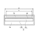
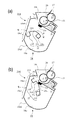
図3(a)は、現像ユニット4の構成を示す断面図であり、トナー保持部22fが床面側内壁部18a1に当接した状態を示す。なお、現像ユニット4或いはプロセスカートリッジ7の構成や動作について、上、下、垂直、水平といった方向を表す用語は、特に断りのない場合は、図面上でそれらの通常の使用状態において見た時の方向を表す。つまり、現像ユニット4或いはプロセスカートリッジ7の通常の使用状態は、適正に配置された画像形成装置本体に対して適正に装着され、画像形成動作に供し得る状態である。   FIG. 3A is a cross-sectional view showing the configuration of the developing unit 4 and shows a state in which the toner holding portion 22f is in contact with the floor side inner wall portion 18a1. In addition, as for the configuration and operation of the developing unit 4 or the process cartridge 7, the terms representing the directions such as up, down, vertical, and horizontal are those in the normal use state on the drawing unless otherwise specified. Represents a direction. That is, the normal use state of the developing unit 4 or the process cartridge 7 is a state in which the developing unit 4 or the process cartridge 7 can be properly mounted on the properly arranged image forming apparatus main body and used for an image forming operation.

現像ユニット4にはトナー収納室18a及び現像室18bが形成されている。現像室18bには、現像ローラ17、供給ローラ20及び現像ブレード21等が収納されている。トナー収納室18aには、現像室18bに供給されるトナーが収納されると共に、現像室18bにトナーを供給する搬送部材22が設けられている。そして、トナー収納室18aは、現像室18bよりも鉛直方向で下方に配置されている。従って、トナー収納室18aから現像室18bへと重力に反してトナーを搬送する必要がある。   In the developing unit 4, a toner storage chamber 18a and a developing chamber 18b are formed. In the developing chamber 18b, a developing roller 17, a supply roller 20, a developing blade 21, and the like are accommodated. The toner storage chamber 18a is provided with a transport member 22 that stores toner supplied to the development chamber 18b and supplies toner to the development chamber 18b. The toner storage chamber 18a is disposed below the developing chamber 18b in the vertical direction. Therefore, it is necessary to convey the toner against the gravity from the toner storage chamber 18a to the development chamber 18b.

前述のように、従来、重力に反してトナーを搬送する構成を有する場合に、簡易で小型化に対応し易い構成にて効率良く良好なトナーの搬送性を得ることは難しかった。現像ローラ17や供給ローラ20が設けられた現像室18bへのトナー供給不良が発生すると、画像白抜け(出力画像上で局所的にトナーが載らずに抜け落ちる現象)等の画像不具合の発生に繋がる。従って、重力に反してトナーを搬送する構成を有する場合に、簡便で、低コスト化、小型化が容易な構成にて、トナー供給不良による画像白抜け等の画像不具合を抑制することが望ましい。   As described above, conventionally, when the toner is transported against gravity, it has been difficult to obtain a good toner transport efficiency with a simple and easy-to-support structure. If a toner supply failure to the developing chamber 18b in which the developing roller 17 and the supply roller 20 are provided occurs, an image defect such as an image white defect (a phenomenon in which the toner is not locally deposited on the output image) occurs. . Therefore, in the case where the toner is transported against gravity, it is desirable to suppress image defects such as image blank due to poor toner supply with a simple, low-cost, and compact structure.

そこで、実施例1では、現像ユニット4は、次の構成を有している。即ち、現像ユニット4は、現像枠体18の内部に形成された、現像室18b及びトナー収納室18aを有する。現像室18bには、現像ローラ17及び供給ローラ20が設けられている。また、トナー収納室18aは、現像室18bの下方に配置されている。ここで、トナー収納室18aは、現像室18bに供給するトナーを収納する。現像室18bとトナー収納室18aとの間には、トナー収納室18a及び現像室18bを区画する区画壁26が形成されている。また、この区画壁26には、区画壁26を貫通する開口部18cが形成されている。ここで、開口部18cは、トナー収納室18aの上方に設けられている。また、トナー収納室18aの内部には、現像室18bにトナーを供給するための弾性を有する搬送部材22が回転可能に設けられている。   Therefore, in the first embodiment, the developing unit 4 has the following configuration. That is, the developing unit 4 includes a developing chamber 18 b and a toner storage chamber 18 a that are formed inside the developing frame 18. A developing roller 17 and a supply roller 20 are provided in the developing chamber 18b. Further, the toner storage chamber 18a is disposed below the developing chamber 18b. Here, the toner storage chamber 18a stores toner to be supplied to the developing chamber 18b. A partition wall 26 that partitions the toner storage chamber 18a and the development chamber 18b is formed between the development chamber 18b and the toner storage chamber 18a. The partition wall 26 is formed with an opening 18 c that penetrates the partition wall 26. Here, the opening 18c is provided above the toner storage chamber 18a. In addition, a conveyance member 22 having elasticity for supplying toner to the developing chamber 18b is rotatably provided in the toner storage chamber 18a.

図3(a)に示されるように、トナー収納室18aは、床面側内壁部18a1、『変形部』であるガイド部18a2、『復元部』である復元部18a4が形成されている。トナー収納室18aにはトナーが貯められる。床面側内壁部18a1は、トナーが貯められ、搬送部材22が回転するときに当接する曲面である。搬送部材22が回転すると、搬送部材22の先端が床面側内壁部18a1に当接していくが当接力は増減せず、搬送部材22の変形量はほぼ一定であり、搬送部材22の先端に掬い上げられたトナーは搬送部材22の回転方向の下流側へと搬送されていく。   As shown in FIG. 3A, the toner storage chamber 18a has a floor-side inner wall portion 18a1, a guide portion 18a2 which is a “deformation portion”, and a restoration portion 18a4 which is a “restoration portion”. Toner is stored in the toner storage chamber 18a. The floor side inner wall portion 18a1 is a curved surface that abuts when the toner is stored and the conveying member 22 rotates. When the conveying member 22 rotates, the tip of the conveying member 22 comes into contact with the floor-side inner wall portion 18a1, but the contact force does not increase or decrease, and the deformation amount of the conveying member 22 is substantially constant. The toner thus scooped up is conveyed downstream in the rotation direction of the conveying member 22.

『変形部』であるガイド部18a2は、搬送部材22が回転するときに当接する板面である。すなわち、ガイド部18a2は、搬送部材22の回転に伴う接触力に増加に対応して搬送部材22に付与する反力を増加させ、搬送部材22を変形させる板面である。このために、搬送部材22が回転すると、搬送部材22の先端がガイド部18a2に当接していって当接力が増加し、ガイド部18a2の反力の増加によって搬送部材22は変形する。   The guide portion 18a2 that is a “deformation portion” is a plate surface that abuts when the transport member 22 rotates. That is, the guide portion 18a2 is a plate surface that deforms the conveying member 22 by increasing a reaction force applied to the conveying member 22 corresponding to an increase in the contact force accompanying the rotation of the conveying member 22. For this reason, when the conveying member 22 rotates, the leading end of the conveying member 22 abuts on the guide portion 18a2, and the abutting force increases, and the conveying member 22 is deformed by an increase in the reaction force of the guide portion 18a2.

『復元部』である復元部18a4は、搬送部材22が回転するときに当接する板面である。すなわち、復元部18a4は、搬送部材22の回転に伴う接触力の減少に対応して搬送部材22に付与する反力を減少させ、搬送部材22を復元させる板面である。このために、搬送部材22が回転すると、搬送部材22の先端が復元部18a4から離間していって当接力が減少し、復元部18a4の反力の減少によって搬送部材22は復元する。   The restoration part 18a4 which is a "restoration part" is a plate surface that comes into contact when the transport member 22 rotates. That is, the restoring portion 18 a 4 is a plate surface that reduces the reaction force applied to the transport member 22 in response to a decrease in contact force accompanying the rotation of the transport member 22 and restores the transport member 22. For this reason, when the conveying member 22 rotates, the leading end of the conveying member 22 is separated from the restoring portion 18a4 and the contact force is reduced, and the conveying member 22 is restored by a decrease in the reaction force of the restoring portion 18a4.

ガイド部18a2及び復元部18a4は断面視で直線状に形成されている。ガイド部18a2及び復元部18a4の間の境には境界部qが定められる。境界部qは、開口部18cの下端よりも下方に設けられている。また、床面側内壁部18a1及びガイド部18a2の間の境には下側角部sが形成され、復元部18a4の上端には開口部18cへと屈曲する上側角部tが形成されている。   The guide part 18a2 and the restoring part 18a4 are formed in a straight line in a cross-sectional view. A boundary portion q is defined at the boundary between the guide portion 18a2 and the restoration portion 18a4. The boundary part q is provided below the lower end of the opening 18c. In addition, a lower corner s is formed at the boundary between the floor inner wall 18a1 and the guide 18a2, and an upper corner t that is bent toward the opening 18c is formed at the upper end of the restoring portion 18a4. .

また、図3(a)に示されるように、トナー収納室18aの内部には搬送部材22が回転自在に配置されている。搬送部材22は、開口部18cよりも下方に配置されてトナー収納室18aの内部で回転自在な『回転軸』である搬送支持軸22bを有する。この搬送支持軸22bは、図示しない駆動手段から回転駆動力を受ける。また、搬送部材22は、搬送支持軸22bに基端部が固定されて板状に延びて弾性(可撓性)を有するシート部22aを有する。さらに、搬送部材22は、シート部22aの回転半径方向の先端側で、シート部22aの回転方向の側の面に形成されて現像剤を保持可能な凹部22f1を有する『現像剤保持部』であるトナー保持部22fを有する。この凹部22f1によってトナーが掬い取られるようになっている。   Further, as shown in FIG. 3A, a conveying member 22 is rotatably disposed inside the toner storage chamber 18a. The transport member 22 has a transport support shaft 22b that is a “rotary shaft” that is disposed below the opening 18c and is rotatable within the toner storage chamber 18a. The transport support shaft 22b receives a rotational driving force from a driving means (not shown). Further, the transport member 22 has a sheet portion 22a having a base end portion fixed to the transport support shaft 22b and extending in a plate shape and having elasticity (flexibility). Further, the conveying member 22 is a “developer holding portion” having a recess 22f1 formed on the surface of the sheet portion 22a in the rotation radius direction and on the surface in the rotation direction side of the sheet portion 22a and capable of holding the developer. A toner holding portion 22f is provided. The recess 22f1 scoops out toner.

搬送部材22は、その長手方向(回転軸線方向)の両端部において、トナー収納室18aを形成する現像枠体18に回転可能に支持されている。搬送部材22は、図示しない駆動手段(駆動源)により回転方向G(時計方向)に回転駆動するようになっている。そして、搬送部材22は、回転によってトナーをトナー収納室18aから現像室18bへと搬送するようになっている。なお、搬送支持軸22bは、感光体ドラム1、現像ローラ17及び供給ローラ20の長手方向(回転軸線方向)と略平行に、トナー収納室18aの長手方向の全域にわたって配置されている。シート部22aは、搬送支持軸22bの長手方向(回転軸線方向)の略全域にわたって延在する連続したシート(板状部材)である。そして、シート部22aは、搬送支持軸22bの長手方向と略直交する方向(回転半径方向)の一端部(基端部)において搬送支持軸22bに取り付けられている。また、シート部22aは、例えば、ポリエステルフィルム、ポリフェニレンスルフィドフィルム、ポリカーボネートフィルムなどの可撓性の樹脂製シートを用いて好適に作製することができる。シート部22aの厚みは、50μm〜250μmが好適である。   The transport member 22 is rotatably supported by the developing frame 18 that forms the toner storage chamber 18a at both ends in the longitudinal direction (rotation axis direction). The conveying member 22 is rotationally driven in the rotational direction G (clockwise) by a driving means (drive source) (not shown). The transport member 22 transports toner from the toner storage chamber 18a to the development chamber 18b by rotation. The conveyance support shaft 22b is disposed over the entire region in the longitudinal direction of the toner storage chamber 18a substantially parallel to the longitudinal direction (rotational axis direction) of the photosensitive drum 1, the developing roller 17, and the supply roller 20. The sheet portion 22a is a continuous sheet (plate-like member) that extends over substantially the entire region in the longitudinal direction (rotational axis direction) of the conveyance support shaft 22b. The sheet portion 22a is attached to the conveyance support shaft 22b at one end (base end portion) in a direction (rotational radius direction) substantially orthogonal to the longitudinal direction of the conveyance support shaft 22b. Moreover, the sheet | seat part 22a can be suitably produced, for example using flexible resin-made sheets, such as a polyester film, a polyphenylene sulfide film, and a polycarbonate film. The thickness of the sheet portion 22a is preferably 50 μm to 250 μm.

トナー保持部22fは、回転方向の上流側の面に凹部22f1を有する。トナー保持部22fは、搬送支持軸22bの長手方向(回転軸線方向)の略全域にわたって延在する連続した凹形状部材である。そして、トナー保持部22fは、シート部22aにおけるトナー収納室18aの内壁に近い位置に設けられている。トナー保持部22fの長手方向の両端には側壁が設けられており、トナー保持部22fの内部のトナーが側面からこぼれ落ちることを防止する。トナー保持部22fは、アクリル樹脂、ポリカーボネート樹脂又はポリアセタ−ル樹脂、ポリエチレンテレフタレート樹脂(PET)、ポリオレフィン樹脂、ポリスチレン樹脂、ポリエステル樹脂などの樹脂製シートを用いて作製してもよい。トナー保持部22fの厚みは、50μm〜1000μmが好適である。   The toner holding portion 22f has a recess 22f1 on the upstream surface in the rotation direction. The toner holding portion 22f is a continuous concave member that extends over substantially the entire region in the longitudinal direction (rotational axis direction) of the conveyance support shaft 22b. The toner holding portion 22f is provided at a position near the inner wall of the toner storage chamber 18a in the sheet portion 22a. Side walls are provided at both ends in the longitudinal direction of the toner holding portion 22f to prevent the toner inside the toner holding portion 22f from spilling from the side surface. The toner holding portion 22f may be manufactured using a resin sheet such as acrylic resin, polycarbonate resin or polyacetal resin, polyethylene terephthalate resin (PET), polyolefin resin, polystyrene resin, polyester resin. The thickness of the toner holding part 22f is preferably 50 μm to 1000 μm.

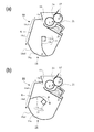
また、図4(a)に示す通り、凹部22f1及び開口部18cが対向する状態では、凹部22f1の揺動方向(移動方向)で凹部22f1及び開口部18cが少なくとも一部で重なるように設定されている。そして、搬送部材22が回転すると現像剤がトナー収納室18aから開口部18cを通過して現像室18bへと搬送されるようになっている。搬送部材22が回転した時に、トナー保持部22fの少なくとも一部が開口部18cと重なるように設定されている。さらに、図4(b)に示す通り、搬送部材22と区画壁26が接触した時には、以下のようになっている。すなわち、開口部18cに沿う平面に垂直な第1方向Jと、トナー保持部22fの接触直前の移動方向を示す第2方向Kのなす角αは、10°である。すなわち、第1方向Jと第2方向Kはほぼ平行である。 Further, as shown in FIG. 4A, in a state where the recess 22f1 and the opening 18c face each other, the recess 22f1 and the opening 18c are set to overlap at least partially in the swinging direction (movement direction) of the recess 22f1. ing. When the conveying member 22 rotates, the developer passes through the opening 18c from the toner storage chamber 18a and is conveyed to the developing chamber 18b. When the conveying member 22 rotates, at least a part of the toner holding portion 22f is set to overlap the opening portion 18c. Further, as shown in FIG. 4B, when the conveying member 22 and the partition wall 26 come into contact with each other, the following is performed. That is, the angle α formed by the first direction J perpendicular to the plane along the opening 18c and the second direction K indicating the moving direction immediately before the contact of the toner holding portion 22f is 10 °. That is, the first direction J and the second direction K are substantially parallel.

次に、図3(a)〜図4(b)を参照し、現像ユニット4の内部の搬送部材22の動作を詳述する。図3(a)に示されるように、搬送部材22のシート部22aの先端側にはトナー保持部22fが形成されている。このトナー保持部22fがトナー収納室18aの最下部付近の床面側内壁部18a1に当接している。この状態で、搬送部材22が回転することで、トナー保持部22fの凹部22f1の内部に、トナー収納室18aの最下部付近から保持可能な分のトナーを掬い取ることができる。   Next, with reference to FIGS. 3A to 4B, the operation of the conveying member 22 inside the developing unit 4 will be described in detail. As shown in FIG. 3A, a toner holding portion 22 f is formed on the leading end side of the sheet portion 22 a of the conveying member 22. The toner holding portion 22f is in contact with the floor side inner wall portion 18a1 near the lowermost portion of the toner storage chamber 18a. In this state, when the conveying member 22 rotates, the toner that can be held from the vicinity of the lowermost portion of the toner storage chamber 18a can be scooped into the recess 22f1 of the toner holding portion 22f.

図3(b)は、現像ユニット4の構成を示す断面図であり、トナー保持部22fがガイド部18a2に当接した状態を示す。図3(b)に示されるように、トナー収納室18aには、『変形部』であるガイド部18a2及び『復元部』である復元部18a4が形成される。ガイド部18a2は、トナー収納室18aの内壁のうち直線状の部分であって、下側角部sから境界部qまでの内壁面を指す。復元部18a4は、トナー収納室18aの内壁のうち直線状の部分であって、境界部qから上側角部tまでの内壁面を指す。   FIG. 3B is a cross-sectional view showing the configuration of the developing unit 4, and shows a state where the toner holding portion 22f is in contact with the guide portion 18a2. As shown in FIG. 3B, the toner storage chamber 18a is formed with a guide portion 18a2 which is a “deformation portion” and a restoration portion 18a4 which is a “restoration portion”. The guide portion 18a2 is a linear portion of the inner wall of the toner storage chamber 18a and refers to the inner wall surface from the lower corner portion s to the boundary portion q. The restoring portion 18a4 is a linear portion of the inner wall of the toner storage chamber 18a, and indicates the inner wall surface from the boundary portion q to the upper corner portion t.

搬送部材22のトナー保持部22fがガイド部18a2に当接しながら回転すると、搬送部材22がガイド部18a2から受ける反力が増加していく。その結果、搬送部材22の有する弾性力に抗して搬送部材22の特にシート部22aが変形していく。このときに、トナー保持部22fの凹部22f1の内部に掬い取られたトナーは、トナー保持部22fの内壁及びガイド部18a2によって動きが制限されるため、トナー保持部22fに貯まった状態で回転方向の下流側へと搬送される。同時に、シート部22aにおけるトナー保持部22fよりも搬送支持軸22bの側の部位に積もったトナーは、図3(b)の矢印Pの方向に落下していく。   When the toner holding portion 22f of the conveying member 22 rotates while contacting the guide portion 18a2, the reaction force received by the conveying member 22 from the guide portion 18a2 increases. As a result, particularly the sheet portion 22a of the conveying member 22 is deformed against the elastic force of the conveying member 22. At this time, the movement of the toner scooped into the concave portion 22f1 of the toner holding portion 22f is restricted by the inner wall of the toner holding portion 22f and the guide portion 18a2, so that the rotation direction is stored in the toner holding portion 22f. It is conveyed to the downstream side. At the same time, the toner accumulated in the portion of the sheet portion 22a closer to the conveyance support shaft 22b than the toner holding portion 22f falls in the direction of arrow P in FIG.

そして、搬送部材22が復元部18a4に当接しながら回転すると、搬送部材22が復元部18a4から受ける反力が減少していく。その結果、搬送部材22の有する弾性力によって搬送部材22が復元していく。復元部18a4は、トナー収納室18aの内部で、搬送部材22の回転方向においてガイド部18a2よりも下流側、かつ、開口部18cよりも上流側に設けられている。復元部18a4は、搬送部材22とトナー収納室18aの内壁との接触を解放するための部分とも言える。復元部18a4は、トナー収納室18aの内壁のうち境界部qから上側角部tまでの箇所を指す。搬送部材22の回転に伴って搬送部材22の自由端側の先端が境界部qを接触しながら通過して復元部18a4を接触しながら通過する過程で、搬送部材22がトナー収納室18aの内壁に対する当接状態から解放される。すると、搬送部材22は、ガイド部18a2によって変形していた状態から解放されて、それ自体の弾性復元力によって自然状態(元の形状)へと復元する。   When the conveying member 22 rotates while contacting the restoring portion 18a4, the reaction force received by the conveying member 22 from the restoring portion 18a4 decreases. As a result, the conveying member 22 is restored by the elastic force of the conveying member 22. The restoring portion 18a4 is provided in the toner storage chamber 18a on the downstream side of the guide portion 18a2 and the upstream side of the opening portion 18c in the rotation direction of the conveying member 22. The restoring portion 18a4 can also be said to be a portion for releasing the contact between the conveying member 22 and the inner wall of the toner storage chamber 18a. The restoration unit 18a4 indicates a portion from the boundary q to the upper corner t of the inner wall of the toner storage chamber 18a. As the conveyance member 22 rotates, the free end of the conveyance member 22 passes through the boundary portion q while contacting the restoring portion 18a4, and the conveyance member 22 passes through the inner wall of the toner storage chamber 18a. It is released from the contact state with respect to. Then, the conveying member 22 is released from the state of being deformed by the guide portion 18a2, and is restored to the natural state (original shape) by its own elastic restoring force.

図4(a)は、現像ユニット4の構成を示す断面図であり、トナー保持部22fが開口部18cに対向する状態を示す。図4(a)に示されるように、搬送部材22が更に回転すると、搬送部材22の凹部22f1が開口部18cと対向し、搬送部材22が区画壁26に接触する直前状態に至る。トナー保持部22fよりも搬送支持軸22b側のシート部22aに積もったトナーは、図4(a)中で矢印Pの方向に落下する。このときに、搬送部材22が復元する形状変化で、トナー保持部22fは搬送部材22の回転方向に素早く加速するが、凹部22f1の内部のトナーは凹部22f1の内壁に強く押し付けられて強く保持されてトナー保持部22fの外に出て行かない。   FIG. 4A is a cross-sectional view showing the configuration of the developing unit 4, and shows a state where the toner holding portion 22f faces the opening 18c. As shown in FIG. 4A, when the transport member 22 further rotates, the recess 22f1 of the transport member 22 faces the opening 18c, and a state immediately before the transport member 22 contacts the partition wall 26 is reached. The toner that has accumulated on the sheet portion 22a closer to the conveyance support shaft 22b than the toner holding portion 22f falls in the direction of arrow P in FIG. At this time, the toner holding portion 22f quickly accelerates in the rotation direction of the conveying member 22 due to the shape change that the conveying member 22 restores, but the toner inside the concave portion 22f1 is strongly pressed against the inner wall of the concave portion 22f1 and strongly held. The toner does not go out of the toner holding portion 22f.

図4(b)は、現像ユニット4の構成を示す断面図であり、シート部22aが区画壁26に突き当たった状態を示す。図4(b)に示されるように、前述の開口部18cは、復元部18a4よりも搬送部材22の回転方向の下流側に位置する。また、境界部qは、開口部18cの最下端よりも下方に設けられている。そして、搬送部材22は、境界部qを通過すると、搬送部材22の弾性力に基づいて復元し、シート部22aが区画壁26における開口部18cの下方の領域(『現像剤容器接触部』)に接触可能な位置まで一気に回転する。従って、搬送部材22が境界部qを通過した瞬間に、搬送部材22は弾性力でもって開口部18cの周辺の区画壁26に突き当たる。シート部22aが区画壁26に突き当たることによってトナー保持部22fは急激に減速するが、トナー保持部22fの内部のトナーは慣性力によって周方向の力を受けてトナー保持部22fの外へと放出される。 FIG. 4B is a cross-sectional view showing the configuration of the developing unit 4 and shows a state in which the sheet portion 22 a has abutted against the partition wall 26. As shown in FIG. 4B, the above-described opening 18c is located downstream of the restoring portion 18a4 in the rotation direction of the transport member 22. Moreover, the boundary part q is provided below the lowest end of the opening part 18c. Then, when the conveying member 22 passes through the boundary portion q, the conveying member 22 is restored based on the elastic force of the conveying member 22, and the sheet portion 22a is a region below the opening 18c in the partition wall 26 ("developer container contact portion"). Rotates all the way to a position where it can be touched. Therefore, at the moment when the conveying member 22 passes through the boundary portion q, the conveying member 22 hits the partition wall 26 around the opening 18c with an elastic force. When the sheet portion 22a hits the partition wall 26, the toner holding portion 22f rapidly decelerates, but the toner inside the toner holding portion 22f receives a circumferential force due to inertial force and is released to the outside of the toner holding portion 22f. Is done.

また、搬送部材22が区画壁26に接触した状態では、以下のことが言える。すなわち、開口部18cに沿う平面に垂直な第1方向J、及び、シート部22aが区画壁26(現像剤容器接触部)に接触するときに凹部22f1が揺動する第2方向Kが略平行である。これにより、トナー保持部22fの外に放出されたトナーは、開口部18cを通って現像室18bに効率良く入っていく。 Further, the following can be said in a state where the conveying member 22 is in contact with the partition wall 26. That is, the first direction J perpendicular to the plane along the opening 18c and the second direction K in which the recess 22f1 swings when the sheet portion 22a contacts the partition wall 26 (developer container contact portion) are substantially parallel. It is. As a result, the toner released to the outside of the toner holding portion 22f efficiently enters the developing chamber 18b through the opening 18c.

こうした構成及び作用により、トナー収納室18aの内部のトナー量によらず、トナー収納室18aの最下部から一定のトナー量をトナー保持部22fに保持可能である。そのために、より簡易で小型化にも対応し易い構成にて、効率よく良好に重力に反してトナーをトナー収納室18aから現像室18bに搬送される。   With this configuration and operation, a constant toner amount can be held in the toner holding portion 22f from the bottom of the toner storage chamber 18a regardless of the toner amount inside the toner storage chamber 18a. For this reason, the toner is efficiently and satisfactorily conveyed against the gravity from the toner storage chamber 18a to the developing chamber 18b with a simpler configuration that can easily cope with downsizing.

その他の特徴に関して以下で更に詳述する。図4(b)に示されるように、現像室18bの内部には開口部18cと対向する位置に供給ローラ20が配置されている。トナー収納室18aの内部のトナーが開口部18cを介して現像室18bに搬送される。供給ローラ20は、開口部18cとの対向部では表面が上から下へと移動する方向に回転していく。この回転によって、供給ローラ20は、開口部18cを通過して現像室18bに供給されたトナーを、区画壁26に沿って下方に向けて取り込んでいく。また、開口部18cの下端は、供給ローラ20の下端よりも上方に配置される。この配置により、現像室18bに収納されるトナーの剤面(集合としてのトナーの表面)は、開口部18cの下端に依存する。従って、トナーの剤面が供給ローラ20の下端よりも上方になる。そのため、供給ローラ20の表面とトナーとの接触面積が増加して供給ローラ20へのトナー供給効率が向上する。   Other features are described in further detail below. As shown in FIG. 4B, a supply roller 20 is disposed in the developing chamber 18b at a position facing the opening 18c. The toner inside the toner storage chamber 18a is conveyed to the developing chamber 18b through the opening 18c. The supply roller 20 rotates in the direction in which the surface moves from top to bottom at the portion facing the opening 18c. By this rotation, the supply roller 20 takes in the toner supplied to the developing chamber 18 b through the opening 18 c downward along the partition wall 26. The lower end of the opening 18 c is disposed above the lower end of the supply roller 20. With this arrangement, the toner surface (the surface of the toner as a group) of the toner stored in the developing chamber 18b depends on the lower end of the opening 18c. Therefore, the toner surface is above the lower end of the supply roller 20. For this reason, the contact area between the surface of the supply roller 20 and the toner increases, and the efficiency of supplying toner to the supply roller 20 is improved.

図5は、図2の矢印Vの方向から見た搬送部材22及び開口部18cの構成を示す断面図である。図5に示されるトナー保持部22fの長手方向の長さMは、好ましくは開口部18cの長手方向の長さNよりも長い方が良い。これにより、トナー保持部22fのうち搬送部材22の回転中心から最も遠い部位が、開口部18cの下端に引っかかって、搬送部材22の動きが不安定になることが防止される。   FIG. 5 is a cross-sectional view showing the configuration of the conveying member 22 and the opening 18c as seen from the direction of the arrow V in FIG. The length M in the longitudinal direction of the toner holding portion 22f shown in FIG. 5 is preferably longer than the length N in the longitudinal direction of the opening 18c. As a result, the portion of the toner holding portion 22f that is farthest from the rotation center of the conveying member 22 is prevented from being caught by the lower end of the opening 18c, and the movement of the conveying member 22 is prevented from becoming unstable.

[実施例1の効果]
前述の実施例1の構成によれば、より簡易で小型化にも対応し易い構成にて、効率よく良好に重力に反してトナーをトナー収納室18aから現像室18bに搬送することができる。また、トナー収納室18aの内部のトナー量によらず、トナー収納室18aの最下部から一定のトナー量をトナー保持部22fに保持可能である。従って、トナー収納室18aの内部のトナー量によらず、効率よく良好に重力に反してトナーをトナー収納室18aから現像室18bに搬送することができる。
[Effect of Example 1]
According to the configuration of the first embodiment described above, the toner can be efficiently and satisfactorily conveyed against the gravity from the toner storage chamber 18a to the developing chamber 18b with a configuration that is simpler and can easily cope with downsizing. Further, regardless of the toner amount inside the toner storage chamber 18a, a constant toner amount can be held in the toner holding portion 22f from the lowermost portion of the toner storage chamber 18a. Therefore, regardless of the amount of toner inside the toner storage chamber 18a, the toner can be efficiently and satisfactorily conveyed from the toner storage chamber 18a to the developing chamber 18b against gravity.

簡易な構成について詳述する。実施例1の構成によれば、搬送部材22は、実質的にシート部22aとそれを支持する搬送支持軸22bと、トナー収納室18aの内部のトナーを保持して開口部18cにトナーを搬送するトナー保持部22fとから成る簡易な構成である。そのため、トナーを上方へ搬送する手段として、例えばスクリューなどを用いる構成に比べて、より安価な構成である。   A simple configuration will be described in detail. According to the configuration of the first exemplary embodiment, the conveyance member 22 substantially holds the toner in the toner storage chamber 18a while conveying the toner to the opening 18c while holding the toner in the toner storage chamber 18a, the conveyance support shaft 22b that supports the sheet portion 22a. The toner holding unit 22f is a simple configuration. Therefore, it is a cheaper configuration as compared with a configuration using, for example, a screw or the like as means for conveying the toner upward.

小型化について詳述する。実施例1の構成によれば、搬送部材22に弾性を有するシート部22aを用いるため、トナーはトナー保持部22fに保持された状態で、シート部22aの弾性復元力により跳ね上げられる。シート部22aが弾性変形可能であることから、図2において、プロセスカートリッジの左右方向の幅を縮めることができる。このため、例えばトナー収納室18aの断面がほぼ円形状で、搬送部材がトナーを保持したまま現像室18bへ搬送するような構成に比べて、トナー収納室18aの幅を縮め、小型化することできる。また、トナー収納室18aの小型化に伴い、現像ユニット4、プロセスカートリッジ7及び画像形成装置100を小型化が実現される。   The downsizing will be described in detail. According to the configuration of the first exemplary embodiment, since the elastic sheet portion 22a is used for the conveying member 22, the toner is jumped up by the elastic restoring force of the sheet portion 22a while being held by the toner holding portion 22f. Since the sheet portion 22a can be elastically deformed, the width of the process cartridge in the left-right direction can be reduced in FIG. Therefore, for example, the width of the toner storage chamber 18a can be reduced and the size can be reduced as compared with a configuration in which the toner storage chamber 18a has a substantially circular cross section and the transfer member transfers the toner to the developing chamber 18b while holding the toner. it can. Further, along with the miniaturization of the toner storage chamber 18a, the development unit 4, the process cartridge 7, and the image forming apparatus 100 can be miniaturized.

前述の実施例1の構成によれば、重力に反して良好にトナーを搬送できるので、例えば中間転写ベルト5の鉛直方向の下方にプロセスカートリッジ7を配置する構成などを実現することが可能である。これにより、例えば、スキャナユニット3と定着装置10とを離れた場所に配置することが可能であり、定着装置10の熱がスキャナユニット3に及ぼす影響が低減される。また、定着装置10の熱がスキャナユニット3に及ぼす影響を低減するための空間を廃除するか又は減少させることができる。これにより、例えば画像形成装置100の高さを抑えるなど、画像形成装置100の小型化が実現される。さらに、定着装置10を、現像ユニット4及びプロセスカートリッジ7に対し、中間転写ベルト5を挟んで上方の離れた位置に配置することができる。このため、定着装置10の熱が現像ユニット4及びプロセスカートリッジ7に与える影響が低減される。定着装置10の熱が現像ユニット4又はプロセスカートリッジ7に与える影響を低減するための空間が排除又は低減される。これにより、例えば画像形成装置100の高さを抑えるなど、画像形成装置100の小型化が実現される。   According to the configuration of the first embodiment described above, the toner can be transported satisfactorily against gravity, so that, for example, a configuration in which the process cartridge 7 is disposed below the intermediate transfer belt 5 in the vertical direction can be realized. . As a result, for example, the scanner unit 3 and the fixing device 10 can be arranged at a distance from each other, and the influence of the heat of the fixing device 10 on the scanner unit 3 is reduced. Further, the space for reducing the influence of the heat of the fixing device 10 on the scanner unit 3 can be eliminated or reduced. As a result, the image forming apparatus 100 can be reduced in size, for example, by suppressing the height of the image forming apparatus 100. Further, the fixing device 10 can be arranged at a position away from the developing unit 4 and the process cartridge 7 with the intermediate transfer belt 5 interposed therebetween. For this reason, the influence of the heat of the fixing device 10 on the developing unit 4 and the process cartridge 7 is reduced. A space for reducing the influence of the heat of the fixing device 10 on the developing unit 4 or the process cartridge 7 is eliminated or reduced. As a result, the image forming apparatus 100 can be reduced in size, for example, by suppressing the height of the image forming apparatus 100.

図6は、実施例2に係る現像ユニット204の構成を示す断面図であり、トナー保持部22fが床面側内壁部18a1に当接した状態を示す。実施例2の現像ユニット204の構成のうち実施例1の現像ユニット4と同一の構成及び効果に関しては、同一の符号を用いて説明を適宜省略する。実施例2においても、実施例1と同様の画像形成装置に適用することができるため、画像形成装置の説明は省略する。実施例2の現像ユニット204が実施例1の現像ユニット4と異なる点は、区画壁26の一部の表面に、搬送部材22が接触する区画壁突起部26aが取り付けられている点である。   FIG. 6 is a cross-sectional view illustrating the configuration of the developing unit 204 according to the second embodiment, in which the toner holding portion 22f is in contact with the floor-side inner wall portion 18a1. Among the configurations of the developing unit 204 of the second embodiment, the same configurations and effects as those of the developing unit 4 of the first embodiment are denoted by the same reference numerals, and description thereof is omitted as appropriate. Since the second embodiment can be applied to the same image forming apparatus as that of the first embodiment, the description of the image forming apparatus is omitted. The developing unit 204 of the second embodiment is different from the developing unit 4 of the first embodiment in that a partition wall protrusion 26 a that contacts the conveyance member 22 is attached to a part of the surface of the partition wall 26.

『現像剤容器接触部』である区画壁突起部26aは、搬送支持軸22bよりも上方で区画壁26における開口部18cの下部側に配置され、シート部22aと接触可能な構成となっている。そして、シート部22aが区画壁突起部26aに接触すると、シート部22a及び区画壁突起部26aの接触点を支点として凹部22f1が開口部18cに向かって揺動するようになっている。また、区画壁突起部26a及び搬送支持軸22bの間の寸法は、シート部22aが区画壁突起部26aに接触した場合に、シート部22a及びトナー保持部22fが弾性変形しながら通過可能な寸法に設定されている。   The partition wall projection 26a, which is a “developer container contact portion”, is disposed above the transport support shaft 22b and below the opening 18c in the partition wall 26, and is configured to be able to contact the sheet portion 22a. . When the sheet portion 22a comes into contact with the partition wall projection 26a, the recess 22f1 swings toward the opening 18c with the contact point between the sheet portion 22a and the partition wall projection 26a as a fulcrum. Further, the dimension between the partition wall protrusion 26a and the conveyance support shaft 22b is a dimension that allows the sheet part 22a and the toner holding part 22f to pass while elastically deforming when the sheet part 22a contacts the partition wall protrusion 26a. Is set to

図6に示されるように、トナー保持部22fがトナー収納室18aの最下部付近を通過する場合には、搬送部材22が回転することにより、トナー保持部22fの凹部22f1の内部には、トナーが掬い取られていく。   As shown in FIG. 6, when the toner holding part 22f passes near the lowermost part of the toner storage chamber 18a, the conveying member 22 rotates, so that the toner holding part 22f has toner in the concave part 22f1. Will be scolded.

図7(a)は、現像ユニット204の構成を示す断面図であり、トナー保持部22fがガイド部18a2に当接した状態を示す。トナー保持部22fの内部に掬い取られたトナーは、トナー保持部22fの内壁及びガイド部18a2によって動きが制限されるために、搬送部材22の回転方向の下流側の凹部22f1に保持された状態で搬送される。同時に、トナー保持部22fよりも搬送支持軸22bの側のシート部22aに積もったトナーは、矢印Pの方向に落下する。ここまでは、実施例1と同様の作用である。   FIG. 7A is a cross-sectional view showing the configuration of the developing unit 204, and shows a state where the toner holding portion 22f is in contact with the guide portion 18a2. The toner scooped inside the toner holding portion 22f is restricted in movement by the inner wall of the toner holding portion 22f and the guide portion 18a2, so that the toner is held in the concave portion 22f1 on the downstream side in the rotation direction of the conveying member 22. It is conveyed by. At the same time, the toner accumulated on the sheet portion 22a closer to the conveyance support shaft 22b than the toner holding portion 22f falls in the direction of the arrow P. Up to this point, the operation is the same as that of the first embodiment.

図7(b)は、現像ユニット204の構成を示す断面図であり、シート部22aが区画壁突起部26aに当接した状態を示す。図7(b)に示されるように、搬送部材22が区画壁突起部26aに接触した瞬間では、シート部22a及び区画壁突起部26aが接触する位置のうち、シート部22aにおける搬送支持軸22bに最も近い最近接触部位22a1が接触することになる。   FIG. 7B is a cross-sectional view showing the configuration of the developing unit 204, and shows a state in which the sheet portion 22a is in contact with the partition wall protrusion 26a. As shown in FIG. 7B, at the moment when the conveying member 22 contacts the partition wall projection 26a, the conveyance support shaft 22b in the sheet portion 22a out of the positions where the sheet portion 22a and the partition wall projection 26a contact. The closest contact portion 22a1 closest to the contact will come into contact.

ここで、区画壁突起部26aのうち、搬送部材22と接触する部位を接触角部26a1とする。接触角部26a1は、開口部18cよりも下方、かつ、搬送支持軸22bの回転中心より上方に位置する。トナー保持部22fは、区画壁突起部26aと接触するシート部22aのうち、最も搬送部材22の搬送支持軸22b(回転中心)に近い最近接触部位22a1から、最も搬送部材22の搬送支持軸22b(回転中心)から遠い部位までの間に設定される。   Here, the part which contacts the conveyance member 22 among the partition wall protrusion parts 26a is referred to as a contact angle part 26a1. The contact corner 26a1 is located below the opening 18c and above the rotation center of the transport support shaft 22b. The toner holding portion 22f is the closest to the conveyance support shaft 22b (rotation center) of the conveyance member 22 closest to the conveyance support shaft 22b (rotation center) of the sheet portion 22a that is in contact with the partition wall projection 26a, and the conveyance support shaft 22b of the conveyance member 22 is closest. It is set between the (rotation center) and the far part.

搬送部材22と区画壁26が接触する直前までは、搬送部材22の復元方向への形状変化によって、トナー保持部22fは素早く加速される。しがし、トナー保持部22fの凹部22f1の内部のトナーはトナー保持部22fの内壁に強く押し付けられ強く保持され、トナー保持部22fの外に出て行かない。   Until just before the conveying member 22 and the partition wall 26 come into contact, the toner holding portion 22f is quickly accelerated by the shape change of the conveying member 22 in the restoring direction. However, the toner inside the concave portion 22f1 of the toner holding portion 22f is strongly pressed against the inner wall of the toner holding portion 22f and is strongly held, and does not go out of the toner holding portion 22f.

それに対して、区画壁26に区画壁突起部26aが設けられる場合には、以下の効果がある。すなわち、搬送部材22が回転してシート部22aが区画壁突起部26aに接触する。そうすると、シート部22aのうち最も搬送部材22に近い区画壁突起部26aとの最近接触部位22a1からトナー保持部22fまでが、最近接触部位22a1を支点として、シート部22aの回転方向の下流側に変形する。そして、トナー保持部22fの内部のトナーは、トナー保持部22fの接触直前の移動方向に向かって、勢いよくトナー保持部22fの外に放出される。   On the other hand, when the partition wall projection 26a is provided on the partition wall 26, the following effects are obtained. That is, the conveyance member 22 rotates and the sheet portion 22a comes into contact with the partition wall protrusion 26a. Then, the closest contact portion 22a1 to the toner holding portion 22f with the partition wall projection 26a closest to the conveying member 22 in the sheet portion 22a is located downstream of the rotation direction of the sheet portion 22a with the closest contact portion 22a1 as a fulcrum. Deform. Then, the toner inside the toner holding unit 22f is vigorously discharged out of the toner holding unit 22f in the moving direction immediately before the contact of the toner holding unit 22f.

そして、図4(b)の場合と同様に、搬送部材22と区画壁突起部26aが接触した時、開口部18cに沿う平面に垂直な第1方向Jと、トナー保持部22fの接触直前の移動方向を示す第2方向Kはほぼ平行である。これにより、トナー保持部22fの外に放出されたトナーは、開口部18cを通って現像室18bに効率良く入る。   Similarly to the case of FIG. 4B, when the conveying member 22 and the partition wall projection 26a come into contact with each other, the first direction J perpendicular to the plane along the opening 18c and immediately before the contact with the toner holding unit 22f. The second direction K indicating the moving direction is substantially parallel. Thereby, the toner released out of the toner holding portion 22f efficiently enters the developing chamber 18b through the opening 18c.

こうした構成及び作用により、トナー収納室18aの内部のトナー量によらず、トナー収納室18aの最下部から一定のトナー量をトナー保持部22fに保持可能である。そのために、より簡易で小型化にも対応し易い構成にて、効率よく良好に重力に反してトナーをトナー収納室18aから現像室18bに搬送される。   With this configuration and operation, a constant toner amount can be held in the toner holding portion 22f from the bottom of the toner storage chamber 18a regardless of the toner amount inside the toner storage chamber 18a. For this reason, the toner is efficiently and satisfactorily conveyed against the gravity from the toner storage chamber 18a to the developing chamber 18b with a simpler configuration that can easily cope with downsizing.

図8(a)は、第1比較例に係る現像ユニット64の構成を示す断面図であり、シート部22aの先端が床面側内壁部18a1に当接した状態を示す。第1比較例の現像ユニット64が実施例1及び2の現像ユニット4と異なる点は、トナー保持部22fを備えない点である。図8(a)に示されるように、シート部22aの先端がトナー収納室18aの床面側内壁部18a1の最下部の付近と当接する当接角度θは60°である。このように、当接角度θが大きいので、搬送部材22が回転すると、トナー収納室18aの最下部の付近のトナーがガイド部18a2まで持ち上げられる。   FIG. 8A is a cross-sectional view showing a configuration of the developing unit 64 according to the first comparative example, and shows a state in which the leading end of the sheet portion 22a is in contact with the floor side inner wall portion 18a1. The developing unit 64 of the first comparative example is different from the developing unit 4 of Examples 1 and 2 in that the toner holding unit 22f is not provided. As shown in FIG. 8A, the contact angle θ at which the front end of the sheet portion 22a contacts the vicinity of the lowermost portion of the floor side inner wall portion 18a1 of the toner storage chamber 18a is 60 °. As described above, since the contact angle θ is large, when the transport member 22 rotates, the toner near the lowermost portion of the toner storage chamber 18a is lifted up to the guide portion 18a2.

図8(b)は、第1比較例に係る現像ユニット64の構成を示す断面図であり、シート部22aの先端がガイド部18a2に当接した状態を示す。図8(b)に示されるように、シート部22aが汲み上げたトナーのうち、シート部22aの回転半径方向の先端側のトナーは、搬送部材22及びガイド部18a2によって動きが制限されるため、搬送部材22の回転方向の下流側に保持された状態で搬送される。同時に、シート部22aが持ち上げたトナーのうち、シート部22aの回転中心側のトナーは、矢印Pの方向に落下する。   FIG. 8B is a cross-sectional view showing the configuration of the developing unit 64 according to the first comparative example, and shows a state in which the leading end of the sheet portion 22a is in contact with the guide portion 18a2. As shown in FIG. 8B, among the toner pumped up by the sheet portion 22a, the movement of the toner on the leading end side in the rotational radius direction of the sheet portion 22a is limited by the conveying member 22 and the guide portion 18a2. It is conveyed while being held on the downstream side in the rotation direction of the conveying member 22. At the same time, of the toner lifted by the sheet portion 22a, the toner on the rotation center side of the sheet portion 22a falls in the direction of the arrow P.

図9は、第1比較例に係る現像ユニット64の構成を示す断面図であり、シート部22aの先端が区画壁26に接触する直前の状態を示す。図9に示されるように、搬送部材22の回転に伴って搬送部材22の自由端側の先端がガイド部18a2を通過した後に、搬送部材22のトナー収納室18aの内壁との当接が解放される。すると、搬送部材22は、ガイド部18a2によって変形していた状態から解放されて、それ自体の弾性復元力によって自然状態(元の形状)へと復元する。この搬送部材22の復元方向への形状変化によって、搬送部材22上に担持されて搬送されていたトナーは、開口部18cへ向けて重力に反して飛翔する。この開口部18cは、復元部18a4よりも搬送部材22の回転方向の下流側に位置する。   FIG. 9 is a cross-sectional view illustrating a configuration of the developing unit 64 according to the first comparative example, and illustrates a state immediately before the leading end of the sheet portion 22a contacts the partition wall 26. As shown in FIG. 9, the contact of the conveying member 22 with the inner wall of the toner storage chamber 18a is released after the free end of the conveying member 22 passes through the guide portion 18a2 as the conveying member 22 rotates. Is done. Then, the conveying member 22 is released from the state of being deformed by the guide portion 18a2, and is restored to the natural state (original shape) by its own elastic restoring force. Due to the shape change of the conveying member 22 in the restoring direction, the toner carried and conveyed on the conveying member 22 flies against the gravity toward the opening 18c. The opening 18c is located downstream of the restoring portion 18a4 in the rotation direction of the conveying member 22.

搬送部材22は、境界部qを通過する場合には、その弾性力による復元によって開口部18cの周辺と接触可能な位置まで回転している。従って、搬送部材22が境界部qから離れた瞬間に、搬送部材22はその弾性力でもって開口部18cの周辺に突き当たる。これにより、トナーを開口部18cへ飛翔させることができる。   When the transport member 22 passes through the boundary portion q, the transport member 22 is rotated to a position where it can come into contact with the periphery of the opening portion 18c by restoration due to its elastic force. Therefore, at the moment when the conveying member 22 is separated from the boundary portion q, the conveying member 22 hits the periphery of the opening 18c with its elastic force. Thereby, the toner can fly to the opening 18c.

しかし、搬送部材22が境界部qから離れ、開口部18cの周辺に突き当たるまでに、搬送部材22が持ち上げたトナーのうち、搬送部材22の回転中心側のトナーは、図9中の矢印Pの方向に落下する。また、搬送部材22が持ち上げたトナーのうち、搬送部材22の自由端側のトナーは、搬送部材22にトナーを保持することができないために、大部分が遠心力で外側に押し出され、図9中の矢印Qの方向に落下する。   However, among the toners lifted by the conveying member 22 until the conveying member 22 moves away from the boundary q and hits the periphery of the opening 18c, the toner on the rotation center side of the conveying member 22 is indicated by the arrow P in FIG. Fall in the direction. Further, among the toner lifted by the conveying member 22, most of the toner on the free end side of the conveying member 22 is pushed out by centrifugal force because the toner cannot be held on the conveying member 22, and FIG. It falls in the direction of arrow Q inside.

すなわち、搬送部材22が境界部qを通過してから開口部18cの周辺に突き当たるまでに、搬送部材22以外にトナーの動きを制限するものが無い。そのために、搬送部材22上のトナーは、開口部18c以外に散逸しやすく、効率よく重力に反してトナーをトナー収納室18aから現像室18bに搬送することは難しい。   That is, there is nothing other than the conveying member 22 that restricts the movement of the toner until the conveying member 22 hits the periphery of the opening 18c after passing through the boundary portion q. For this reason, the toner on the transport member 22 is likely to dissipate outside the opening 18c, and it is difficult to efficiently transport the toner from the toner storage chamber 18a to the developing chamber 18b against gravity.

ここで、搬送部材22がガイド部18a2まで持ち上げたトナーのうち、開口部18cに搬送できる割合はほぼ一定である。従って、トナー収納室18aの内部のトナー量が少ない場合、搬送部材22がガイド部18a2まで持ち上げるトナー量が減るため、効率よく重力に反してトナーをトナー収納室18aから現像室18bに搬送することは特に難しい。   Here, of the toner lifted up to the guide portion 18a2 by the transport member 22, the proportion of the toner that can be transported to the opening portion 18c is substantially constant. Therefore, when the amount of toner in the toner storage chamber 18a is small, the amount of toner that the transport member 22 lifts up to the guide portion 18a2 is reduced, so that the toner can be efficiently transported from the toner storage chamber 18a to the development chamber 18b against gravity. Is particularly difficult.

図10(a)は、第2比較例に係る現像ユニット74の構成を示す断面図であり、シート部22aの先端が床面側内壁部18a1に当接した状態を示す。第2比較例の現像ユニット74が実施例1及び2の現像ユニット4と異なる点は、トナー保持部22fを備えない点と、搬送支持軸22bに直接にシート部22aが取り付けられない点である。第2比較例の現像ユニット74では、搬送支持軸22bに対して、力が加わっても変形しないシート貼り付け部22cが取付けられる。更に、シート貼り付け部22cの回転中心から最も遠い部位に対して、シート部22aが取付けられる。   FIG. 10A is a cross-sectional view showing a configuration of the developing unit 74 according to the second comparative example, and shows a state in which the leading end of the sheet portion 22a is in contact with the floor side inner wall portion 18a1. The development unit 74 of the second comparative example is different from the development unit 4 of Examples 1 and 2 in that the toner holding unit 22f is not provided and the sheet unit 22a is not directly attached to the conveyance support shaft 22b. . In the developing unit 74 of the second comparative example, a sheet attaching portion 22c that is not deformed even when a force is applied is attached to the conveyance support shaft 22b. Further, the sheet portion 22a is attached to a portion farthest from the rotation center of the sheet attaching portion 22c.

図10(a)に示されるように、シート部22aの先端がトナー収納室18aの床面側内壁部18a1の最下部の付近と当接する当接角度θは45°である。このように、当接角度θが小さいので、搬送部材22が回転しても、トナー収納室18aの付近の多くのトナーがガイド部18a2まで持ち上げられない。   As shown in FIG. 10A, the contact angle θ at which the tip of the sheet portion 22a contacts the vicinity of the lowermost portion of the floor side inner wall portion 18a1 of the toner storage chamber 18a is 45 °. As described above, since the contact angle θ is small, a large amount of toner in the vicinity of the toner storage chamber 18a cannot be lifted up to the guide portion 18a2 even if the conveying member 22 rotates.

図10(b)は、第2比較例に係る現像ユニット74の構成を示す断面図であり、シート部22aの先端がガイド部18a2に当接した状態を示す。図10(b)に示されるように、搬送部材22が持ち上げたトナーのうち、搬送部材22の自由端側のトナーは、搬送部材22及びガイド部18a2によって動きが制限されるため、搬送部材22の回転方向下流側に保持された状態で搬送される。ただし、シート部22a及びガイド部18a2の当接角度θは23°である。このように、当接角度θが小さいので、搬送部材22が回転しても、搬送部材22の自由端側のトナーの全てを搬送することはできない。また、搬送部材22が持ち上げたトナーのうち、搬送部材22の回転中心側のトナーは、図10(b)中の矢印Pの方向に落下する。   FIG. 10B is a cross-sectional view showing the configuration of the developing unit 74 according to the second comparative example, and shows a state in which the leading end of the sheet portion 22a is in contact with the guide portion 18a2. As shown in FIG. 10B, among the toners lifted by the conveyance member 22, the movement of the toner on the free end side of the conveyance member 22 is restricted by the conveyance member 22 and the guide portion 18 a 2. It is conveyed while being held downstream in the rotation direction. However, the contact angle θ between the sheet portion 22a and the guide portion 18a2 is 23 °. As described above, since the contact angle θ is small, even if the conveying member 22 rotates, it is not possible to convey all of the toner on the free end side of the conveying member 22. Of the toner lifted by the conveying member 22, the toner on the rotation center side of the conveying member 22 falls in the direction of arrow P in FIG.

図11(a)は、第2比較例に係る現像ユニット74の構成を示す断面図であり、シート部22aの先端が境界部qを通過する状態を示す。図11(a)に示されるように、シート部22aの先端が境界部qを通過すると、シート部22a及びトナー収納室18aの内壁の当接状態が解放される。すると、搬送部材22は、ガイド部18a2によって変形していた状態から解放されて、それ自体の弾性復元力によって自然状態(元の形状)へと復元する。   FIG. 11A is a cross-sectional view showing a configuration of the developing unit 74 according to the second comparative example, and shows a state in which the leading end of the sheet portion 22a passes through the boundary portion q. As shown in FIG. 11A, when the leading end of the sheet portion 22a passes through the boundary portion q, the contact state between the sheet portion 22a and the inner wall of the toner storage chamber 18a is released. Then, the conveying member 22 is released from the state of being deformed by the guide portion 18a2, and is restored to the natural state (original shape) by its own elastic restoring force.

しかし、搬送部材22の自由端側の先端は、境界部qから離れる際には、その弾性によって復元しても、開口部18cの周辺とは非接触な位置までしか回転できない。すなわち、搬送部材22の弾性力を用いて、搬送部材22の自由端側のトナーを開口部18cへ飛翔させることができない。   However, the free end of the conveying member 22 can only rotate to a position that is not in contact with the periphery of the opening 18c, even if it is restored by its elasticity when it is separated from the boundary q. In other words, the toner on the free end side of the conveying member 22 cannot fly to the opening 18c by using the elastic force of the conveying member 22.

図11(b)は、第2比較例に係る現像ユニット74の構成を示す断面図であり、シート部22aの先端が区画壁26に接触する状態を示す。図11(b)に示されるように、シート部22aの自由端側に残ったトナーも、開口部18cの下端の区画壁26によって擦りきられて、図11(b)中の矢印Q方向に落下する。   FIG. 11B is a cross-sectional view showing a configuration of the developing unit 74 according to the second comparative example, and shows a state in which the leading end of the sheet portion 22 a is in contact with the partition wall 26. As shown in FIG. 11B, the toner remaining on the free end side of the sheet portion 22a is also rubbed by the partition wall 26 at the lower end of the opening 18c, and is moved in the direction of arrow Q in FIG. Fall.

このように、シート部22aの弾性力を用いて、シート部22aの自由端側のトナーを開口部18cへ飛翔させることができない。また、シート部22aの自由端側に残ったトナーも、開口部18c下端の区画壁26によって擦りきられて落下するため、効率よく重力に反してトナーをトナー収納室18aから現像室18bに搬送することは難しい。   Thus, the toner on the free end side of the sheet portion 22a cannot be caused to fly to the opening portion 18c by using the elastic force of the sheet portion 22a. Further, the toner remaining on the free end side of the sheet portion 22a is also rubbed and dropped by the partition wall 26 at the lower end of the opening portion 18c, so that the toner is efficiently conveyed from the toner storage chamber 18a to the developing chamber 18b against gravity. Difficult to do.

図12(a)は、第3比較例に係る現像ユニット84の構成を示す断面図であり、シート部22aの先端が床面側内壁部18a1に当接した状態を示す。第3比較例の現像ユニット84が実施例1及び実施例2の現像ユニット4と異なる点は、トナー保持部22fを備えない点と、シート部22aに搬送部材突起部22dが設けられる点である。図12(a)に示されるように、第3比較例の現像ユニット84では、搬送部材22がトナー収納室18aの最下部の付近で床面側内壁部18a1に当接すると、シート部22aの先端がトナー収納室18aの最下部の付近と当接する当接角度θは60°である。このように、当接角度θが大きいので、搬送部材22が回転すると、トナー収納室18aの最下部の付近のトナーがガイド部18a2まで持ち上げられる。   FIG. 12A is a cross-sectional view showing a configuration of the developing unit 84 according to the third comparative example, and shows a state in which the front end of the sheet portion 22a is in contact with the floor side inner wall portion 18a1. The development unit 84 of the third comparative example is different from the development unit 4 of Example 1 and Example 2 in that the toner holding part 22f is not provided and the conveyance member protrusion part 22d is provided on the sheet part 22a. . As shown in FIG. 12A, in the developing unit 84 of the third comparative example, when the conveying member 22 comes into contact with the floor side inner wall portion 18a1 in the vicinity of the lowermost portion of the toner storage chamber 18a, the sheet portion 22a The contact angle θ at which the tip contacts the vicinity of the lowermost portion of the toner storage chamber 18a is 60 °. As described above, since the contact angle θ is large, when the transport member 22 rotates, the toner near the lowermost portion of the toner storage chamber 18a is lifted up to the guide portion 18a2.

図12(b)は、第3比較例に係る現像ユニット84の構成を示す断面図であり、シート部22aの先端がガイド部18a2に当接した状態を示す。図12(b)に示されるように、搬送部材22が持ち上げたトナーのうち、搬送部材突起部22dよりも自由端側のトナーは、搬送部材突起部22d、搬送部材22及びガイド部18a2によって動きが制限される。そのために、搬送部材22の回転方向の下流側に保持された状態で搬送される。しかし、搬送部材22が持ち上げたトナーのうち、搬送部材突起部22dよりも回転中心側のトナーは、図12(b)中の矢印Pの方向に落下する。   FIG. 12B is a cross-sectional view illustrating a configuration of the developing unit 84 according to the third comparative example, and illustrates a state in which the leading end of the sheet portion 22a is in contact with the guide portion 18a2. As shown in FIG. 12B, of the toner lifted by the conveying member 22, the toner on the free end side with respect to the conveying member protruding portion 22d moves by the conveying member protruding portion 22d, the conveying member 22, and the guide portion 18a2. Is limited. Therefore, it is conveyed in a state of being held on the downstream side in the rotation direction of the conveying member 22. However, of the toner lifted by the conveying member 22, the toner closer to the rotation center than the conveying member protrusion 22d falls in the direction of arrow P in FIG.

図13は、第3比較例に係る現像ユニット84の構成を示す断面図であり、シート部22aの先端が区画壁26と接触する直前の状態を示す。搬送部材22の回転に伴って搬送部材22の自由端側の先端がガイド部18a2を通過した後に、シート部22a及びトナー収納室18aの内壁の当接が解放される。すると、搬送部材22は、ガイド部18a2によって変形していた状態から解放されて、それ自体の弾性復元力によって自然状態(元の形状)へと復元する。この搬送部材22の復元方向への形状変化によって、搬送部材22上に担持されて搬送されていたトナーは、開口部18cへ向けて重力に反して飛翔する。この開口部18cは、復元部18a4よりも搬送部材22の回転方向の下流側に位置する。   FIG. 13 is a cross-sectional view illustrating a configuration of the developing unit 84 according to the third comparative example, and illustrates a state immediately before the leading end of the sheet portion 22a contacts the partition wall 26. As the transport member 22 rotates, the free end of the transport member 22 passes through the guide portion 18a2, and then the contact between the sheet portion 22a and the inner wall of the toner storage chamber 18a is released. Then, the conveying member 22 is released from the state of being deformed by the guide portion 18a2, and is restored to the natural state (original shape) by its own elastic restoring force. Due to the shape change of the conveying member 22 in the restoring direction, the toner carried and conveyed on the conveying member 22 flies against the gravity toward the opening 18c. The opening 18c is located downstream of the restoring portion 18a4 in the rotation direction of the conveying member 22.

搬送部材22は、境界部qから離れる際には、その弾性による復元によって開口部18cの周辺と接触可能な位置まで回転している。従って、搬送部材22が境界部qから離れた瞬間に、搬送部材22はその弾性力でもって開口部18cの周辺に突き当たる。これにより、トナーを開口部18cへ飛翔させることができる。   When the conveying member 22 is separated from the boundary portion q, the conveying member 22 is rotated to a position where it can come into contact with the periphery of the opening 18c due to its elastic recovery. Therefore, at the moment when the conveying member 22 is separated from the boundary portion q, the conveying member 22 hits the periphery of the opening 18c with its elastic force. Thereby, the toner can fly to the opening 18c.

しかし、搬送部材22が境界部qから離れ、開口部18cの周辺に突き当たるまでに、搬送部材22が持ち上げたトナーのうち、搬送部材突起部22dよりも自由端側のトナーは、搬送部材22にトナーを保持することができない。そのために、大部分が遠心力で外側に押し出され、図13中の矢印Qの方向に落下する。   However, of the toner lifted by the conveying member 22 until the conveying member 22 moves away from the boundary q and hits the periphery of the opening 18c, the toner on the free end side of the conveying member protrusion 22d is transferred to the conveying member 22. The toner cannot be retained. For that purpose, most is pushed outward by centrifugal force and falls in the direction of arrow Q in FIG.

すなわち、搬送部材22が境界部qから離れ、開口部18cの周辺に突き当たるまでに、搬送部材22と搬送部材突起部22d以外にトナーの動きを制限するものが無い。そのために、搬送部材22上のトナーは、開口部18c以外に散逸しやすく、効率よく重力に反してトナーをトナー収納室18aから現像室18bに搬送することは難しい。   That is, there is nothing that restricts the movement of the toner other than the conveyance member 22 and the conveyance member protrusion 22d until the conveyance member 22 moves away from the boundary portion q and hits the periphery of the opening 18c. For this reason, the toner on the transport member 22 is likely to dissipate outside the opening 18c, and it is difficult to efficiently transport the toner from the toner storage chamber 18a to the developing chamber 18b against gravity.

ここで、搬送部材22がガイド部18a2まで持ち上げたトナーのうち、開口部18cに搬送できる割合はほぼ一定である。従って、トナー収納室18aの内部のトナー量が少ない場合、搬送部材22がガイド部18a2まで持ち上げるトナー量が減るため、効率よく重力に反してトナーをトナー収納室18aから現像室18bに搬送することは特に難しい。   Here, of the toner lifted up to the guide portion 18a2 by the transport member 22, the proportion of the toner that can be transported to the opening portion 18c is substantially constant. Therefore, when the amount of toner in the toner storage chamber 18a is small, the amount of toner that the transport member 22 lifts up to the guide portion 18a2 is reduced, so that the toner can be efficiently transported from the toner storage chamber 18a to the development chamber 18b against gravity. Is particularly difficult.

[トナー収納室から現像室へのトナーの供給を評価する方法]
本発明では、トナー収納室18aから現像室18bへのトナーの供給を評価するために以下の方法を用いた。現像室18bからのトナー消費速度が最も速いのは、ベタ画像を連続して出力する場合である。トナー収納室18aから現像室18bへのトナーの供給速度が不足していると、トナー収納室18aから現像室18bへのトナーの供給速度よりも、現像室18bの内部からのトナー消費速度が上回り、現像室18bの内部のトナー不足が発生する。現像室18bの内部のトナー量が減り過ぎるとベタ画像を出力した時に、ベタ画像がトナー不足で白く抜ける。本発明では、ベタ画像を連続して出力しても、ベタ画像がトナー不足で白く抜けないことを実現する。そこで、ベタ画像を連続して出力し、ベタ画像の画像不良の有無を確認することで、トナー収納室18aから現像室18bへのトナーの供給を評価する。以下で、詳細に説明する。
[Method for evaluating toner supply from toner storage chamber to developing chamber]
In the present invention, the following method is used to evaluate the supply of toner from the toner storage chamber 18a to the developing chamber 18b. The toner consumption rate from the developing chamber 18b is the fastest when continuous images are output continuously. If the toner supply speed from the toner storage chamber 18a to the development chamber 18b is insufficient, the toner consumption speed from the inside of the development chamber 18b is higher than the toner supply speed from the toner storage chamber 18a to the development chamber 18b. In addition, toner shortage inside the developing chamber 18b occurs. If the amount of toner in the developing chamber 18b is too small, when a solid image is output, the solid image is whitened due to insufficient toner. In the present invention, even if solid images are output continuously, the solid image is realized so that it does not fall out white due to toner shortage. Therefore, the supply of toner from the toner storage chamber 18a to the developing chamber 18b is evaluated by continuously outputting solid images and checking the presence or absence of image defects in the solid images. This will be described in detail below.

ベタ画像評価は、画像形成装置を評価環境23℃、50%Rhにて1日放置して当該環境になじませた後、100枚印字後に行った。100枚の印字テストは、画像比率が5%の横線の記録画像を連続的に通紙して行った。画像評価はベタ画像を連続で3枚出力し、3枚目のベタ画像の出力先端と後端の濃度差から評価をX−Rite社製のSpectroDensitometer 500を用いて行った。印字テスト及び評価画像は単色で出力した。また、トナー収納室18aに充填するトナー量を2水準(200g、50g)設定し、それぞれについて比較している。評価にあたって、○は、ベタ画像において、紙先端と紙後端での濃度差が0.2未満の場合、△は、ベタ画像において、紙先端と紙後端での濃度差が0.2〜0.4未満の場合、×は、ベタ画像において、紙先端と紙後端での濃度差が0.4以上の場合とする。   The solid image evaluation was performed after printing the 100 sheets after allowing the image forming apparatus to stand in the evaluation environment at 23 ° C. and 50% Rh for one day to adjust to the environment. The printing test for 100 sheets was performed by continuously passing a horizontal line recorded image having an image ratio of 5%. For the image evaluation, three solid images were continuously output, and evaluation was performed using a SpectroDensitometer 500 manufactured by X-Rite from the density difference between the output leading edge and the trailing edge of the third solid image. The print test and evaluation image were output in a single color. In addition, two levels (200 g and 50 g) of toner amounts to be filled in the toner storage chamber 18a are set and compared. In the evaluation, ◯ indicates that the density difference between the leading edge of the paper and the trailing edge of the paper is less than 0.2 in the solid image, and Δ indicates that the density difference between the leading edge of the paper and the trailing edge of the paper is 0.2 to If it is less than 0.4, x means that the density difference between the leading edge of the paper and the trailing edge of the paper is 0.4 or more in the solid image.

[実施例1〜実施例2及び第1比較例〜第3比較例の評価結果]
表1に、前述の評価方法に基づいた実施例1〜実施例2及び第1比較例〜第3比較例に適用した評価結果の比較表を示す。
[Evaluation results of Examples 1 to 2 and First Comparative Example to Third Comparative Example]
Table 1 shows a comparison table of evaluation results applied to Examples 1 to 2 and First Comparative Example to Third Comparative Example based on the above-described evaluation method.

Figure 0005534730
実施例1では、トナー収納室18aに充填するトナー量が200g、50g両方の条件で評価結果を導出したが、トナー収納室18aから現像室18bへのトナーの供給が共に充分であった。以下で原理を説明する。まず、搬送部材22が回転することで、トナー保持部22fの内部に、トナー収納室18aの最下部付近から保持可能な分のトナーを掬い取ることができる。トナー保持部22fの内部に掬い取ったトナーは、トナー保持部22fの内壁及びガイド部18a2によって動きが制限されるため、トナー保持部22fの回転方向の下流側に保持された状態で搬送される。搬送部材22の回転に伴って搬送部材22の自由端側の先端がガイド部18a2を通過した後に、搬送部材22及びトナー収納室18aの内壁の当接が解放される。
Figure 0005534730
In Example 1, the evaluation results were derived under the conditions where the toner amount to be filled in the toner storage chamber 18a was 200 g and 50 g. However, both the toner supply from the toner storage chamber 18a to the developing chamber 18b was sufficient. The principle will be described below. First, as the conveying member 22 rotates, toner that can be held from the vicinity of the lowermost portion of the toner storage chamber 18a can be scooped into the toner holding portion 22f. The toner scooped inside the toner holding portion 22f is transported while being held on the downstream side in the rotation direction of the toner holding portion 22f because the movement is restricted by the inner wall of the toner holding portion 22f and the guide portion 18a2. . As the transport member 22 rotates, the free end of the transport member 22 passes through the guide portion 18a2, and the contact between the transport member 22 and the inner wall of the toner storage chamber 18a is released.

すると、搬送部材22は、ガイド部18a2によって変形していた状態から解放されて、それ自体の弾性復元力によって自然状態(元の形状)へと復元する。搬送部材22の復元方向への形状変化によって、トナー保持部22fは素早く加速するが、トナー保持部22f内のトナーはトナー保持部22fの内壁に強く押し付けられ強く保持され、トナー保持部22fの外に出て行かない。   Then, the conveying member 22 is released from the state of being deformed by the guide portion 18a2, and is restored to the natural state (original shape) by its own elastic restoring force. The toner holding portion 22f quickly accelerates due to the shape change in the restoring direction of the conveying member 22. However, the toner in the toner holding portion 22f is strongly pressed against and strongly held by the inner wall of the toner holding portion 22f. Don't go out.

搬送部材22は、境界部qから離れる際には、その弾性による復元によって開口部18cの周辺と接触可能な位置まで回転している。従って、搬送部材22が境界部qから離れた瞬間に、搬送部材22はその弾性力でもって開口部18cの周辺の区画壁26に突き当たる。   When the conveying member 22 is separated from the boundary portion q, the conveying member 22 is rotated to a position where it can come into contact with the periphery of the opening 18c due to its elastic recovery. Therefore, at the moment when the conveying member 22 is separated from the boundary portion q, the conveying member 22 abuts against the partition wall 26 around the opening 18c with its elastic force.

この時、トナー保持部22fは急減速するが、トナー保持部22f内のトナーは、トナー保持部22fの接触直前の移動方向に向かって、すなわち慣性に従って、トナー保持部22fの外に放出される。図4(b)のように、搬送部材22と区画壁26が接触した時、開口部18cの平面に垂直な第1方向Jと、トナー保持部22fの接触直前の移動方向を示す第2方向Kはほぼ平行である。これにより、トナー保持部22fの外に放出されたトナーは、開口部18cを通って現像室18bに効率良く入る。   At this time, the toner holding portion 22f decelerates rapidly, but the toner in the toner holding portion 22f is released out of the toner holding portion 22f in the moving direction immediately before the contact of the toner holding portion 22f, that is, according to inertia. . As shown in FIG. 4B, when the conveying member 22 and the partition wall 26 contact each other, the first direction J perpendicular to the plane of the opening 18c and the second direction indicating the moving direction immediately before the contact of the toner holding portion 22f. K is almost parallel. Thereby, the toner released out of the toner holding portion 22f efficiently enters the developing chamber 18b through the opening 18c.

これにより、より簡易で小型化にも対応し易い構成にて、効率よく良好に重力に反してトナーをトナー収納室18aから現像室18bに搬送することができる。また、トナー収納室18a内のトナー量によらず、トナー収納室18aの最下部から一定のトナー量をトナー保持部22fに保持可能である。従って、トナー収納室18a内のトナー量によらず、効率よく良好に重力に反してトナーをトナー収納室18aから現像室18bに搬送することができる。   Thus, the toner can be efficiently and satisfactorily conveyed against the gravity from the toner storage chamber 18a to the developing chamber 18b with a simpler configuration that can easily cope with downsizing. Further, regardless of the amount of toner in the toner storage chamber 18a, a constant toner amount can be held in the toner holding portion 22f from the bottom of the toner storage chamber 18a. Therefore, regardless of the amount of toner in the toner storage chamber 18a, the toner can be efficiently and satisfactorily conveyed from the toner storage chamber 18a to the developing chamber 18b against gravity.

実施例2では、トナー収納室18aに充填するトナー量が200g、50g両方の条件で評価結果を導出したが、トナー収納室18aから現像室18bへのトナー供給が共に充分であった。以下で、原理を説明する。まず、搬送部材22が回転することで、トナー保持部22f内に、トナー収納室18aの最下部付近から保持可能な分のトナーを掬い取ることができる。トナー保持部22f内に掬い取ったトナーは、トナー保持部22fの内壁及びガイド部18a2によって動きが制限されるため、トナー保持部22fの回転方向の下流側に保持された状態で搬送される。トナー保持部22fより搬送支持軸22b側のシート部22aに積もったトナーは、図7(a)中の矢印Pの方向に落下する。ここまでは、実施例1と同様である。   In Example 2, the evaluation results were derived under the conditions where the toner amount to be filled in the toner storage chamber 18a was 200 g and 50 g. However, both the toner supply from the toner storage chamber 18a to the developing chamber 18b was sufficient. The principle will be described below. First, as the conveying member 22 rotates, toner that can be held from the vicinity of the lowermost portion of the toner storage chamber 18a can be scooped into the toner holding portion 22f. The toner scooped into the toner holding portion 22f is transported while being held on the downstream side in the rotation direction of the toner holding portion 22f because the movement is restricted by the inner wall of the toner holding portion 22f and the guide portion 18a2. The toner that has accumulated on the sheet portion 22a closer to the conveyance support shaft 22b than the toner holding portion 22f falls in the direction of arrow P in FIG. The process up to this point is the same as in the first embodiment.

搬送部材22と区画壁26が接触する直前までは、搬送部材22の復元方向への形状変化でトナー保持部22fは素早く加速される。しかしながら、トナー保持部22fの内部のトナーはトナー保持部22fの内壁に強く押し付けられ強く保持され、トナー保持部22fの外に出て行かない。   Until just before the conveying member 22 and the partition wall 26 come into contact, the toner holding portion 22f is quickly accelerated by the shape change in the restoring direction of the conveying member 22. However, the toner inside the toner holding portion 22f is strongly pressed against and strongly held by the inner wall of the toner holding portion 22f, and does not go out of the toner holding portion 22f.

それに対して、搬送部材22と区画壁26が接触すると、区画壁突起部26aと接触するシート部22aのうち最も搬送部材22の回転中心に近い最近接触部位22a1からトナー保持部22fまでが最近接触部位22a1を支点として回転方向の下流側に変形する。そして、トナー保持部22fの内部のトナーは、トナー保持部22fの接触直前の移動方向に向かって、勢いよくトナー保持部22fの外に放出される。   On the other hand, when the conveyance member 22 and the partition wall 26 come into contact with each other, the closest contact portion 22a1 closest to the rotation center of the conveyance member 22 to the toner holding portion 22f among the sheet portions 22a in contact with the partition wall protrusions 26a is the closest contact. The region 22a1 is used as a fulcrum to deform downstream in the rotational direction. Then, the toner inside the toner holding unit 22f is vigorously discharged out of the toner holding unit 22f in the moving direction immediately before the contact of the toner holding unit 22f.

図4(b)のように、搬送部材22と区画壁26が接触した時、開口部18cの平面に垂直な第1方向Jと、トナー保持部22fの接触直前の移動方向の第2方向Kは、ほぼ平行である。これにより、トナー保持部22fの外に放出されたトナーは、開口部18cを通って現像室18bに効率良く入る。   As shown in FIG. 4B, when the conveying member 22 and the partition wall 26 are in contact with each other, the first direction J perpendicular to the plane of the opening 18c and the second direction K in the moving direction immediately before the contact with the toner holding portion 22f. Are almost parallel. Thereby, the toner released out of the toner holding portion 22f efficiently enters the developing chamber 18b through the opening 18c.

これにより、より簡易で小型化にも対応し易い構成にて、効率よく良好に重力に反してトナーをトナー収納室18aから現像室18bに搬送することができる。また、トナー収納室18aの内部のトナー量によらず、トナー収納室18aの最下部から一定のトナー量をトナー保持部22fに保持可能である。従って、トナー収納室18aの内部のトナー量によらず、効率よく良好に重力に反してトナーをトナー収納室18aから現像室18bに搬送することができる。   Thus, the toner can be efficiently and satisfactorily conveyed against the gravity from the toner storage chamber 18a to the developing chamber 18b with a simpler configuration that can easily cope with downsizing. Further, regardless of the toner amount inside the toner storage chamber 18a, a constant toner amount can be held in the toner holding portion 22f from the lowermost portion of the toner storage chamber 18a. Therefore, regardless of the amount of toner inside the toner storage chamber 18a, the toner can be efficiently and satisfactorily conveyed from the toner storage chamber 18a to the developing chamber 18b against gravity.

第1比較例では、トナー収納室18aに充填するトナー量が200g、50g両方の条件で評価結果を導出したが、トナー収納室18aから現像室18bへのトナー供給が共に充分ではなかった。以下で、原理を説明する。搬送部材22と、トナー収納室18aの最下部付近の床面側内壁部18a1とのなす角θは60°であり、当接角θが大きいので、搬送部材22が回転することで、トナー収納室18aの最下部付近のトナーをガイド部18a2まで持ち上げることができる。搬送部材22が持ち上げたトナーのうち、搬送部材22の自由端側のトナーは、搬送部材22及びガイド部18a2によって動きが制限されるため、搬送部材22の回転方向下流側に保持された状態で搬送される。   In the first comparative example, the evaluation results were derived under the conditions where the toner amount to be filled in the toner storage chamber 18a was 200 g and 50 g, but the toner supply from the toner storage chamber 18a to the developing chamber 18b was not sufficient. The principle will be described below. The angle θ formed between the conveying member 22 and the floor side inner wall portion 18a1 near the lowermost portion of the toner storage chamber 18a is 60 °, and the contact angle θ is large. The toner near the lowermost portion of the chamber 18a can be lifted up to the guide portion 18a2. Of the toner lifted by the conveying member 22, the movement of the toner on the free end side of the conveying member 22 is restricted by the conveying member 22 and the guide portion 18a2, so that the toner is held on the downstream side in the rotation direction of the conveying member 22. Be transported.

搬送部材22の回転に伴って搬送部材22の自由端側の先端がガイド部18a2を通過した後に、搬送部材22のトナー収納室18aの内壁との当接が解放される。すると、搬送部材22は、ガイド部18a2によって変形していた状態から解放されて、それ自体の弾性復元力によって自然状態(元の形状)へと復元する。この搬送部材22の復元方向への形状変化によって、搬送部材22上に担持されて搬送されていたトナーは、開口部18cへ向けて重力に反して飛翔する。   As the transport member 22 rotates, the free end of the transport member 22 passes through the guide portion 18a2, and then the contact of the transport member 22 with the inner wall of the toner storage chamber 18a is released. Then, the conveying member 22 is released from the state of being deformed by the guide portion 18a2, and is restored to the natural state (original shape) by its own elastic restoring force. Due to the shape change of the conveying member 22 in the restoring direction, the toner carried and conveyed on the conveying member 22 flies against the gravity toward the opening 18c.

搬送部材22は、境界部qから離れる際には、その弾性による復元によって開口部18cの周辺と接触可能な位置まで回転している。従って、搬送部材22が境界部qから離れた瞬間に、搬送部材22はその弾性力でもって開口部18cの周辺に突き当たる。これにより、トナーを開口部18cへ飛翔させることができる。   When the conveying member 22 is separated from the boundary portion q, the conveying member 22 is rotated to a position where it can come into contact with the periphery of the opening 18c due to its elastic recovery. Therefore, at the moment when the conveying member 22 is separated from the boundary portion q, the conveying member 22 hits the periphery of the opening 18c with its elastic force. Thereby, the toner can fly to the opening 18c.

しかし、搬送部材22が境界部qから離れ、開口部18cの周辺に突き当たるまでに、搬送部材22が持ち上げたトナーのうち、搬送部材22の回転中心側のトナーは、図8(b)中の矢印P方向に落下する。また、搬送部材22が持ち上げたトナーのうち、搬送部材22の自由端側のトナーは、搬送部材22にトナーを保持することができないために、大部分が遠心力で外側に押し出され、図9中の矢印Q方向に落下する。   However, among the toners lifted by the conveying member 22 until the conveying member 22 moves away from the boundary portion q and hits the periphery of the opening 18c, the toner on the rotation center side of the conveying member 22 is in FIG. Drops in the direction of arrow P. Further, among the toner lifted by the conveying member 22, most of the toner on the free end side of the conveying member 22 is pushed out by centrifugal force because the toner cannot be held on the conveying member 22, and FIG. It falls in the direction of arrow Q inside.

すなわち、搬送部材22が境界部qから離れ、開口部18cの周辺に突き当たるまでに、搬送部材22以外にトナーの動きを制限するものが無い。そのために、搬送部材22上のトナーは、開口部18c以外に散逸しやすく、効率よく重力に反してトナーをトナー収納室18aから現像室18bに搬送することは難しい。   That is, there is nothing other than the conveying member 22 that restricts the movement of the toner until the conveying member 22 moves away from the boundary portion q and hits the periphery of the opening 18c. For this reason, the toner on the transport member 22 is likely to dissipate outside the opening 18c, and it is difficult to efficiently transport the toner from the toner storage chamber 18a to the developing chamber 18b against gravity.

ここで、搬送部材22がガイド部18a2まで持ち上げたトナーのうち、開口部18cに搬送できる割合はほぼ一定である。従って、トナー収納室18a内のトナー量が少ない場合には、搬送部材22がガイド部18a2まで持ち上げるトナー量が減るため、効率よく重力に反してトナーをトナー収納室18aから現像室18bに搬送することは特に難しい。   Here, of the toner lifted up to the guide portion 18a2 by the transport member 22, the proportion of the toner that can be transported to the opening portion 18c is substantially constant. Accordingly, when the amount of toner in the toner storage chamber 18a is small, the amount of toner that the transport member 22 lifts to the guide portion 18a2 is reduced, so that the toner is efficiently transported from the toner storage chamber 18a to the development chamber 18b against gravity. That is especially difficult.

第2比較例では、トナー収納室18aに充填するトナー量が200g、50g両方の条件で評価結果を導出したが、トナー収納室18aから現像室18bへのトナー供給が共に大変不充分である。以下で、原理を説明する。搬送部材22と、トナー収納室18aの最下部付近の床面側内壁部18a1とのなす角θは45°であり、当接角θが小さいので、搬送部材22が回転することで、トナー収納室18aの最下部付近の多くのトナーをガイド部18a2まで持ち上げることができない。搬送部材22が持ち上げたトナーのうち、搬送部材22の自由端側のトナーは、搬送部材22及びガイド部18a2によって動きが制限されるため、搬送部材22の回転方向の下流側に保持された状態で搬送される。ただし、搬送部材22と、ガイド部18a2とのなす角θは23°であり、当接角θが小さいので、搬送部材22の自由端側のトナーを全て搬送することはできない。   In the second comparative example, the evaluation result was derived under the condition that the toner amount to be filled in the toner storage chamber 18a is 200 g and 50 g. However, both the toner supply from the toner storage chamber 18a to the developing chamber 18b is very insufficient. The principle will be described below. The angle θ formed by the conveying member 22 and the floor-side inner wall 18a1 near the lowermost portion of the toner storage chamber 18a is 45 °, and the contact angle θ is small. A large amount of toner near the lowermost portion of the chamber 18a cannot be lifted up to the guide portion 18a2. Of the toner lifted by the conveying member 22, the movement of the toner on the free end side of the conveying member 22 is restricted by the conveying member 22 and the guide portion 18a2, so that the toner is held downstream in the rotation direction of the conveying member 22. It is conveyed by. However, since the angle θ formed by the conveying member 22 and the guide portion 18a2 is 23 ° and the contact angle θ is small, it is not possible to convey all the toner on the free end side of the conveying member 22.

搬送部材22の回転に伴って搬送部材22の自由端側の先端がガイド部18a2を通過した後に、搬送部材22のトナー収納室18aの内壁との当接が解放される。すると、搬送部材22は、ガイド部18a2によって変形していた状態から解放されて、それ自体の弾性復元力によって自然状態(元の形状)へと復元する。    As the transport member 22 rotates, the free end of the transport member 22 passes through the guide portion 18a2, and then the contact of the transport member 22 with the inner wall of the toner storage chamber 18a is released. Then, the conveying member 22 is released from the state of being deformed by the guide portion 18a2, and is restored to the natural state (original shape) by its own elastic restoring force.

しかし、搬送部材22の自由端側の先端は、境界部qから離れる際には、その弾性による復元しても、開口部18cの周辺とは非接触な位置までしか回転できない。すなわち、搬送部材22の弾性力を用いて、搬送部材22の自由端側のトナーを開口部18cへ飛翔させることができない。また、搬送部材22の自由端側に残ったトナーも、開口部18c下端の区画壁26によって擦りきられて落下する。   However, when the free end of the conveying member 22 moves away from the boundary portion q, it can rotate only to a position that is not in contact with the periphery of the opening 18c even if it is restored by its elasticity. In other words, the toner on the free end side of the conveying member 22 cannot fly to the opening 18c by using the elastic force of the conveying member 22. The toner remaining on the free end side of the conveying member 22 is also rubbed and dropped by the partition wall 26 at the lower end of the opening 18c.

このように、第2比較例では、搬送部材22の弾性力を用いて、搬送部材22の自由端側のトナーを開口部18cへ飛翔させることができない。また、搬送部材22の自由端側に残ったトナーも、開口部18cの下端の区画壁26によって擦りきられて落下するため、効率よく重力に反してトナーをトナー収納室18aから現像室18bに搬送することは難しい。   Thus, in the second comparative example, the toner on the free end side of the conveying member 22 cannot be caused to fly to the opening 18c by using the elastic force of the conveying member 22. Further, the toner remaining on the free end side of the conveying member 22 is rubbed and dropped by the partition wall 26 at the lower end of the opening 18c, so that the toner is efficiently moved from the toner storage chamber 18a to the developing chamber 18b against gravity. It is difficult to carry.

第3比較例では、トナー収納室18aに充填するトナー量が200g、50g両方の条件で評価結果が導出されたが、トナー収納室18aから現像室18bへのトナー供給が充分ではなかった。以下で、原理を説明する。搬送部材22と、トナー収納室18aの最下部付近の床面側内壁部18a1とのなす角θは60°であり、当接角θが大きいので、搬送部材22が回転することで、トナー収納室18aの最下部付近のトナーをガイド部18a2まで持ち上げることができる。   In the third comparative example, the evaluation results were derived under the conditions where the toner amount to be filled in the toner storage chamber 18a was 200 g and 50 g, but the toner supply from the toner storage chamber 18a to the developing chamber 18b was not sufficient. The principle will be described below. The angle θ formed between the conveying member 22 and the floor side inner wall portion 18a1 near the lowermost portion of the toner storage chamber 18a is 60 °, and the contact angle θ is large. The toner near the lowermost portion of the chamber 18a can be lifted up to the guide portion 18a2.

搬送部材22が持ち上げたトナーのうち、搬送部材突起部22dよりも自由端側のトナーは、搬送部材突起部22d、搬送部材22及びガイド部18a2によって動きが制限されるため、搬送部材22の回転方向下流側に保持された状態で搬送される。   Of the toner lifted by the conveyance member 22, the movement of the toner on the free end side with respect to the conveyance member protrusion 22d is limited by the conveyance member protrusion 22d, the conveyance member 22, and the guide portion 18a2. It is conveyed while being held downstream in the direction.

搬送部材22の回転に伴って搬送部材22の自由端側の先端がガイド部18a2を通過した後に、搬送部材22のトナー収納室18aの内壁との当接が解放される。すると、搬送部材22は、ガイド部18a2によって変形していた状態から解放されて、それ自体の弾性復元力によって自然状態(元の形状)へと復元する。この搬送部材22の復元方向への形状変化によって、搬送部材22上に担持されて搬送されていたトナーは、開口部18cへ向けて重力に反して飛翔する。    As the transport member 22 rotates, the free end of the transport member 22 passes through the guide portion 18a2, and then the contact of the transport member 22 with the inner wall of the toner storage chamber 18a is released. Then, the conveying member 22 is released from the state of being deformed by the guide portion 18a2, and is restored to the natural state (original shape) by its own elastic restoring force. Due to the shape change of the conveying member 22 in the restoring direction, the toner carried and conveyed on the conveying member 22 flies against the gravity toward the opening 18c.

搬送部材22は、境界部qから離れる際には、その弾性による復元によって開口部18cの周辺と接触可能な位置まで回転している。従って、搬送部材22が境界部qから離れた瞬間に、搬送部材22はその弾性力でもって開口部18cの周辺に突き当たる。これにより、トナーを開口部18cへ飛翔させることができる。   When the conveying member 22 is separated from the boundary portion q, the conveying member 22 is rotated to a position where it can come into contact with the periphery of the opening 18c due to its elastic recovery. Therefore, at the moment when the conveying member 22 is separated from the boundary portion q, the conveying member 22 hits the periphery of the opening 18c with its elastic force. Thereby, the toner can fly to the opening 18c.

しかし、搬送部材22が境界部qから離れ、開口部18cの周辺に突き当たるまでに、搬送部材22が持ち上げたトナーのうち、搬送部材突起部22dよりも自由端側のトナーは、搬送部材22にトナーを保持することができない。そのために、大部分が遠心力で外側に押し出され落下する。   However, of the toner lifted by the conveying member 22 until the conveying member 22 moves away from the boundary q and hits the periphery of the opening 18c, the toner on the free end side of the conveying member protrusion 22d is transferred to the conveying member 22. The toner cannot be retained. For that reason, most of them are pushed outward by centrifugal force and fall.

すなわち、搬送部材22が境界部qから離れ、開口部18cの周辺に突き当たるまでに、搬送部材22と搬送部材突起部22d以外にトナーの動きを制限するものが無い。そのために、搬送部材22上のトナーは、開口部18c以外に散逸しやすく、効率よく重力に反してトナーをトナー収納室18aから現像室18bに搬送することは難しい。   That is, there is nothing that restricts the movement of the toner other than the conveyance member 22 and the conveyance member protrusion 22d until the conveyance member 22 moves away from the boundary portion q and hits the periphery of the opening 18c. For this reason, the toner on the transport member 22 is likely to dissipate outside the opening 18c, and it is difficult to efficiently transport the toner from the toner storage chamber 18a to the developing chamber 18b against gravity.

ここで、搬送部材22がガイド部18a2まで持ち上げたトナーの内、開口部18cに搬送できる割合はほぼ一定である。従って、トナー収納室18a内のトナー量が少ない場合、搬送部材22がガイド部18a2まで持ち上げるトナー量が減るため、効率よく重力に反してトナーをトナー収納室18aから現像室18bに搬送することは特に難しい。   Here, the ratio of the toner lifted up to the guide portion 18a2 by the transport member 22 to the opening portion 18c is substantially constant. Therefore, when the amount of toner in the toner storage chamber 18a is small, the amount of toner that the transport member 22 lifts to the guide portion 18a2 decreases, and therefore it is possible to efficiently transport toner from the toner storage chamber 18a to the development chamber 18b against gravity. Especially difficult.

図14は、実施例3に係る現像ユニット304の構成を示す断面図である。実施例3の現像ユニット304の構成のうち実施例1の現像ユニット4と同一の構成及び効果に関しては、同一の符号を用いて説明を適宜省略する。実施例3においても、実施例1と同様の画像形成装置に適用することができるため、画像形成装置の説明は省略する。実施例3の現像ユニット304が実施例1の現像ユニット4と異なる点は、実施例3の現像ユニット304では、ガイド部18a2がトナー収納室18aの内側方向に凸状に形成される点である。   FIG. 14 is a cross-sectional view illustrating a configuration of the developing unit 304 according to the third embodiment. Among the configurations of the developing unit 304 of the third embodiment, the same configurations and effects as those of the developing unit 4 of the first embodiment are denoted by the same reference numerals and description thereof is omitted as appropriate. Since the third embodiment can be applied to the same image forming apparatus as that of the first embodiment, the description of the image forming apparatus is omitted. The developing unit 304 of the third embodiment is different from the developing unit 4 of the first embodiment in that, in the developing unit 304 of the third embodiment, the guide portion 18a2 is formed in a convex shape in the inner direction of the toner storage chamber 18a. .

図14に示されるように、現像ユニット304では、トナー収納室18aには、搬送部材22の回転方向Gにおいて、区画壁26に形成された開口部18cよりも回転方向で上流側に、ガイド部18a2が設けられている。ここで、ガイド部18a2は、搬送部材22の回転に伴ってシート部22aの弾性に抗してシート部22aを変形させるために、搬送部材22と接触する変形部として機能する。特に、ガイド部18a2は、搬送部材22の回転方向Gにおいて、ガイド部18a2と搬送部材22の回転中心の距離が徐々に近くなるように形成されている。   As shown in FIG. 14, in the developing unit 304, the guide portion is provided in the toner storage chamber 18 a on the upstream side in the rotational direction of the opening 18 c formed in the partition wall 26 in the rotational direction G of the conveying member 22. 18a2 is provided. Here, the guide portion 18 a 2 functions as a deforming portion that comes into contact with the conveying member 22 in order to deform the sheet portion 22 a against the elasticity of the sheet portion 22 a as the conveying member 22 rotates. In particular, the guide portion 18 a 2 is formed so that the distance between the guide portion 18 a 2 and the rotation center of the conveyance member 22 gradually decreases in the rotation direction G of the conveyance member 22.

また搬送部材22の回転方向Gにおいて、ガイド部18a2よりも下流側、且つ、開口部18cよりも上流側に、シート部22aの自由端側のトナー保持部22fが接触しない復元部18a4が形成されている。復元部18a4は、トナー収納室18aの内壁の一部によって形成されている。また、復元部18a4は、回転方向Gにおけるガイド部18a2の下流側端部(以下、「境界部」と称す)qよりも更に回転方向で下流側に設けられている。さらに、復元部18a4は、搬送部材22の回転中心からの距離が遠くなるように、トナー収納室18aの内壁に段差18a5が設けられることで形成されている。ここで、段差18a5は、トナーが落下するように、トナーの安息角よりも大きく設定されている。また、復元部18a4では、搬送部材22の自由端側の先端はトナー収納室18aの内壁に接触しない。   Further, in the rotational direction G of the conveying member 22, a restoring portion 18a4 is formed on the downstream side of the guide portion 18a2 and on the upstream side of the opening portion 18c so that the toner holding portion 22f on the free end side of the sheet portion 22a does not contact. ing. The restoring portion 18a4 is formed by a part of the inner wall of the toner storage chamber 18a. Further, the restoring portion 18a4 is provided further downstream in the rotational direction than the downstream end portion (hereinafter referred to as “boundary portion”) q of the guide portion 18a2 in the rotational direction G. Further, the restoring portion 18a4 is formed by providing a step 18a5 on the inner wall of the toner storage chamber 18a so that the distance from the rotation center of the conveying member 22 is increased. Here, the step 18a5 is set larger than the repose angle of the toner so that the toner falls. In the restoring portion 18a4, the free end of the transport member 22 does not contact the inner wall of the toner storage chamber 18a.

搬送部材22が回転して、搬送部材22の自由端側の先端が境界部qを通過した後に、搬送部材22及びトナー収納室18aの内壁(復元部18a4)は接触しなくなっていく。それによって、シート部22aの変形が解放される。このように、弾性を有するシート部22aの変形が解放されると、シート部22aには変形される前の自然状態に戻ろうとする弾性復元力が発生する。   After the conveying member 22 rotates and the free end of the conveying member 22 passes through the boundary portion q, the conveying member 22 and the inner wall (the restoring portion 18a4) of the toner storage chamber 18a are not in contact with each other. Thereby, the deformation of the sheet portion 22a is released. As described above, when the deformation of the elastic sheet portion 22a is released, an elastic restoring force is generated in the sheet portion 22a to return to the natural state before the deformation.

搬送部材22の復元方向への形状変化によって、トナー保持部22fは素早く加速するが、トナー保持部22fの内部のトナーはトナー保持部22fの内壁に強く押し付けられ強く保持され、トナー保持部22fの外に出て行かない。   The toner holding portion 22f quickly accelerates due to the shape change in the restoring direction of the conveying member 22, but the toner inside the toner holding portion 22f is strongly pressed against the inner wall of the toner holding portion 22f and strongly held. Do not go outside.

搬送部材22は、境界部qから離れる際には、その弾性による復元によって開口部18cの周辺と接触可能な位置まで回転している。従って、搬送部材22が境界部qから離れた瞬間に、搬送部材22はその弾性力でもって開口部18cの周辺の区画壁26に突き当たる。   When the conveying member 22 is separated from the boundary portion q, the conveying member 22 is rotated to a position where it can come into contact with the periphery of the opening 18c due to its elastic recovery. Therefore, at the moment when the conveying member 22 is separated from the boundary portion q, the conveying member 22 abuts against the partition wall 26 around the opening 18c with its elastic force.

この時、トナー保持部22fは急減速するが、トナー保持部22fの内部のトナーは、トナー保持部22fの接触直前の移動方向に向かって、すなわち慣性に従って、トナー保持部22fの外に放出される。実施例1と同様に、以下のことが言える。すなわち、搬送部材22と区画壁26の接触時に、開口部18cに沿う平面に垂直な第1方向Jと、トナー保持部22fの接触直前の移動方向である第2方向Kはほぼ平行である。このことは図4(b)に示されるのと同様である。これにより、トナー保持部22fの外に放出されたトナーは、開口部18cを通って現像室18bに効率良く入る。   At this time, the toner holding portion 22f decelerates rapidly, but the toner inside the toner holding portion 22f is released to the outside of the toner holding portion 22f in the moving direction immediately before the contact of the toner holding portion 22f, that is, according to inertia. The As in Example 1, the following can be said. That is, when the conveying member 22 and the partition wall 26 are in contact with each other, the first direction J perpendicular to the plane along the opening 18c and the second direction K, which is the moving direction immediately before the contact with the toner holding portion 22f, are substantially parallel. This is the same as shown in FIG. Thereby, the toner released out of the toner holding portion 22f efficiently enters the developing chamber 18b through the opening 18c.

これにより、より簡易で小型化にも対応し易い構成にて、効率よく良好に重力に反してトナーをトナー収納室18aから現像室18bに搬送することができる。また、トナー収納室18aの内部のトナー量によらず、トナー収納室18aの最下部から一定のトナー量をトナー保持部22fに保持可能である。従って、トナー収納室18a内のトナー量によらず、効率よく良好に重力に反してトナーをトナー収納室18aから現像室18bに搬送することができる。   Thus, the toner can be efficiently and satisfactorily conveyed against the gravity from the toner storage chamber 18a to the developing chamber 18b with a simpler configuration that can easily cope with downsizing. Further, regardless of the toner amount inside the toner storage chamber 18a, a constant toner amount can be held in the toner holding portion 22f from the lowermost portion of the toner storage chamber 18a. Therefore, regardless of the amount of toner in the toner storage chamber 18a, the toner can be efficiently and satisfactorily conveyed from the toner storage chamber 18a to the developing chamber 18b against gravity.

以上説明したように、実施例3の構成によれば、実施例1と同様の効果を得ることができる。また、ガイド部18a2のうち、境界部qが搬送部材22の回転中心に最も近いように構成されている。更には、ガイド部18a2は、搬送部材22の回転方向Gに進むにつれて、ガイド部18a2と搬送部材22の回転中心との距離が徐々に近くなるように形成されている。即ち、ガイド部18a2は、境界部qに近いほど、回転中心に近い。このため、ガイド部18a2を通過する際、シート部22aの変形も徐々に大きくなる。そして、シート部22aの変形は、境界部qで瞬時に解放される。これにより、実施例1よりも多くのトナーを現像室18bへ供給することができる。   As described above, according to the configuration of the third embodiment, the same effect as that of the first embodiment can be obtained. Further, the guide portion 18 a 2 is configured such that the boundary portion q is closest to the rotation center of the transport member 22. Furthermore, the guide portion 18a2 is formed such that the distance between the guide portion 18a2 and the rotation center of the conveyance member 22 gradually decreases as the conveyance member 22 advances in the rotation direction G. That is, the guide portion 18a2 is closer to the rotation center as it is closer to the boundary portion q. For this reason, when passing through the guide portion 18a2, the deformation of the sheet portion 22a gradually increases. Then, the deformation of the sheet portion 22a is instantaneously released at the boundary portion q. As a result, more toner than in the first embodiment can be supplied to the developing chamber 18b.

[その他の実施例]
[トナー収納室の内壁]
実施例1〜3では、搬送部材22がトナー収納室18aのガイド部18a2に当接する例を挙げたが、この構成に限定されるものではない。例えば、実施例1において、搬送部材22及びガイド部18a2が非接触であっても、本発明を適用できる。また、実施例1において、搬送部材22がトナー収納室18aの最下部付近の床面側内壁部18a1に対して非接触であっても近接していれば良い。
[Other Examples]
[Inner wall of toner storage room]
In the first to third embodiments, the conveyance member 22 is in contact with the guide portion 18a2 of the toner storage chamber 18a. However, the configuration is not limited thereto. For example, in the first embodiment, the present invention can be applied even when the conveying member 22 and the guide portion 18a2 are not in contact with each other. In the first exemplary embodiment, the conveying member 22 may be close to the floor-side inner wall 18a1 near the lowermost portion of the toner storage chamber 18a even if it is not in contact with the toner storage chamber 18a.

[搬送部材に通過自在な穴]
図15(a)は、搬送部材22のシート部22aの変形例を示す平面図である。この図15(a)を参照し、シート部22aの変形例を詳述する。実施例1〜3では、搬送部材22のシート部22aには穴が開いていない例を挙げたが、この構成に限定されるものではない。例えば、図15(a)に示されるように、搬送部材22のシート部22aには、トナーが通過自在な穴22gが複数形成されていても良い。トナー収納室18aの内部にトナーが多く充填されている場合、搬送部材22のシート部22aに穴が開いていないと、搬送部材22の回転によりトナー収納室18aの内部のトナー全体を搬送しなければならない。この場合、搬送部材22を回転駆動する駆動負荷が大きくなり、また、トナー収納室18aの内部のトナーに大きな粉圧がかけ続けられトナーが劣化し易くなる。
[Hole that can pass through the conveying member]
FIG. 15A is a plan view illustrating a modified example of the sheet portion 22 a of the conveying member 22. With reference to this Fig.15 (a), the modification of the sheet | seat part 22a is explained in full detail. In Examples 1 to 3, the example in which the hole is not formed in the sheet portion 22a of the conveying member 22 has been described, but the configuration is not limited to this. For example, as shown in FIG. 15A, a plurality of holes 22 g through which toner can pass may be formed in the sheet portion 22 a of the conveying member 22. When a large amount of toner is filled in the toner storage chamber 18a, the entire toner inside the toner storage chamber 18a must be transported by the rotation of the transport member 22 unless the sheet portion 22a of the transport member 22 has a hole. I must. In this case, a driving load for rotationally driving the conveying member 22 is increased, and a large powder pressure is continuously applied to the toner inside the toner storage chamber 18a, so that the toner is easily deteriorated.

それに対して、搬送部材22のシート部22aに穴が形成されている、搬送部材22の回転によりトナー収納室18aの内部のトナーに粉圧がかかると、穴22gをトナーが通ることで粉圧を逃がすことができる。この場合、搬送部材22を回転駆動する駆動負荷が小さくなり、また、トナー収納室18aの内部のトナーに大きな粉圧がかからずトナー劣化しにくくなる。このようにしても、搬送部材22の先端のトナー保持部22fに充分なトナーを保持できるので、トナー収納室18aから現像室18bへ充分な量のトナーを供給することができる。   On the other hand, a hole is formed in the sheet portion 22a of the conveying member 22. When powder pressure is applied to the toner inside the toner storage chamber 18a by the rotation of the conveying member 22, the toner passes through the hole 22g and the powder pressure Can escape. In this case, the driving load for rotationally driving the conveying member 22 is reduced, and the toner in the toner storage chamber 18a is not applied with a large powder pressure, so that the toner is hardly deteriorated. Even in this case, sufficient toner can be held in the toner holding portion 22f at the tip of the conveying member 22, so that a sufficient amount of toner can be supplied from the toner storage chamber 18a to the developing chamber 18b.

図16(a)〜(d)は、搬送部材22のトナー保持部22fの実施例及び変形例を示す断面図である。図16(a)に示されるように、実施例1〜3では、トナー保持部22fは搬送部材22の回転中心から最も遠い位置に配置されたが、必ずしもこの構成に限定されるものではない。すなわち、トナー保持部22fは、区画壁突起部26aと接触するシート部22aのうち、最も搬送部材22に近い最近接触部位22a1から最も搬送部材22から遠い部位までの間に設定されていることが必要である。また、トナー保持部22f及び開口部18cの少なくとも一部が重なることが満たされる必要がある。これらの2つが同時に満たされるならば、実施例1〜3の構成に限定されない。   FIGS. 16A to 16D are cross-sectional views illustrating examples and modifications of the toner holding unit 22 f of the conveying member 22. As shown in FIG. 16A, in the first to third embodiments, the toner holding portion 22f is disposed at a position farthest from the rotation center of the conveying member 22, but the configuration is not necessarily limited thereto. That is, the toner holding portion 22f is set between the closest contact portion 22a1 closest to the conveyance member 22 and the portion farthest from the conveyance member 22 among the sheet portions 22a that are in contact with the partition wall protrusions 26a. is necessary. Further, it is necessary to satisfy that at least a part of the toner holding portion 22f and the opening portion 18c overlap each other. As long as these two are satisfied at the same time, the configuration is not limited to those of the first to third embodiments.

まず、実施例1〜3では、シート部22aよりも先端側にトナー保持部22fが設けられる構成であったが、必ずしもこの構成には限定されない。すなわち、図16(b)に示されるように、搬送部材22の回転中心から最も遠い位置にシート部22aの一部が延びる構成にしても良い。この場合、トナー収納室18aの内壁に搬送部材22が接触した時に、トナー収納室18aの内壁の一部に搬送部材22が引っかかり難くすることができる。   First, in the first to third embodiments, the toner holding portion 22f is provided on the leading end side of the sheet portion 22a. However, the configuration is not necessarily limited thereto. That is, as illustrated in FIG. 16B, a part of the sheet portion 22 a may extend to a position farthest from the rotation center of the conveying member 22. In this case, when the conveyance member 22 comes into contact with the inner wall of the toner storage chamber 18a, the conveyance member 22 can be hardly caught by a part of the inner wall of the toner storage chamber 18a.

また、実施例1〜3では、トナー保持部22fがシート部22aよりも回転方向の上流側に配置される構成であったが、必ずしもこの構成に限定されない。すなわち、搬送部材22の回転方向の上流側の面が凹状に形成されるならば、図16(c)に示されるように、トナー保持部22fの一部を、シート部22aよりも回転方向の下流側に跨って配置されてもよい。   In the first to third embodiments, the toner holding unit 22f is disposed upstream of the sheet unit 22a in the rotation direction. However, the configuration is not necessarily limited thereto. That is, if the upstream surface in the rotation direction of the conveying member 22 is formed in a concave shape, as shown in FIG. 16C, a part of the toner holding portion 22f is moved in the rotation direction from the sheet portion 22a. It may be disposed across the downstream side.

さらに、実施例1〜3では、トナー保持部22fがコの字状に形成される構成であったが、必ずしもこの構成に限定されない。すなわち、図16(d)に示されるように、トナー保持部22fがU字状に形成される構成であっても良い。その他、搬送部材22の回転方向の上流側に凹となるならばどのような形状でも良い。   Furthermore, in the first to third embodiments, the toner holding portion 22f is formed in a U-shape, but is not necessarily limited to this configuration. That is, as shown in FIG. 16D, the toner holding portion 22f may be formed in a U shape. In addition, any shape may be used as long as it is concave on the upstream side in the rotation direction of the conveying member 22.

実施例1では、図4(a)に示されるように、凹部22f1の揺動方向でトナー保持部22fが開口部18cと一部で重なるように配置されたが、必ずしもこの構成に限定されない。例えば、凹部22f1の揺動方向で、開口部18cの全体がトナー保持部22fの凹部22f1と重なるように配置されても良い。これにより、開口部18cの全体に対して、トナー保持部22fの内部のトナーが放出され、トナー収納室18aから現像室18bへ供給できるトナー量が増加する。   In the first exemplary embodiment, as illustrated in FIG. 4A, the toner holding portion 22f is arranged so as to partially overlap the opening portion 18c in the swinging direction of the concave portion 22f1, but the configuration is not necessarily limited thereto. For example, the entire opening 18c may be disposed so as to overlap the recess 22f1 of the toner holding unit 22f in the swinging direction of the recess 22f1. As a result, the toner inside the toner holding portion 22f is released from the entire opening 18c, and the amount of toner that can be supplied from the toner storage chamber 18a to the developing chamber 18b increases.

[トナー保持部の回転方向の下流側への変形]
実施例2では、搬送部材22と区画壁26が接触した時に、以下のことが言える。すなわち、区画壁突起部26aと接触するシート部22aのうち、最も搬送部材22の回転中心に近い最近接触部位22a1からトナー保持部22fまでが、最近接触部位22a1を支点として、シート部22aの回転方向の下流側に変形する。そして、トナー保持部22fの内部のトナーは、トナー保持部22fの接触直前の移動方向に向かって、勢いよくトナー保持部22fの外に放出される。このように、トナー保持部を回転方向の下流側へ変形させられるならば、どのような構成でも良い。
[Deformation of toner holding part toward downstream in rotation direction]
In the second embodiment, the following can be said when the conveying member 22 and the partition wall 26 come into contact with each other. That is, among the sheet portions 22a that are in contact with the partition wall projections 26a, the closest contact portion 22a1 to the toner holding portion 22f that is closest to the rotation center of the conveying member 22 rotates the sheet portion 22a with the closest contact portion 22a1 as a fulcrum. Deforms downstream in the direction. Then, the toner inside the toner holding unit 22f is vigorously discharged out of the toner holding unit 22f in the moving direction immediately before the contact of the toner holding unit 22f. In this way, any configuration may be used as long as the toner holding portion can be deformed downstream in the rotation direction.

図16(e)は、現像ユニット404における搬送部材22の変形例の構成を示す断面図である。図16(e)に示されるように、実施例1のシート部22aにおける回転方向側の面に凸状に形成される搬送部材弾性突起部22eが設けられても良い。搬送部材22の搬送部材弾性突起部22eが区画壁26に接触するように設定する。この場合にも、搬送部材弾性突起部22eからトナー保持部22fまでの部位は、搬送部材弾性突起部22eを支点として回転方向の下流側へと変形する。そして、トナー保持部22fの内部のトナーは、トナー保持部22fの接触直前の移動方向に向かって、勢いよくトナー保持部22fの外に放出される。   FIG. 16E is a cross-sectional view illustrating a configuration of a modified example of the conveying member 22 in the developing unit 404. As shown in FIG. 16E, a conveying member elastic protrusion 22e formed in a convex shape may be provided on the surface in the rotational direction of the sheet portion 22a of the first embodiment. The conveyance member elastic protrusion 22e of the conveyance member 22 is set so as to contact the partition wall 26. Also in this case, the portion from the conveying member elastic protrusion 22e to the toner holding portion 22f is deformed downstream in the rotation direction with the conveying member elastic protrusion 22e as a fulcrum. Then, the toner inside the toner holding unit 22f is vigorously discharged out of the toner holding unit 22f in the moving direction immediately before the contact of the toner holding unit 22f.

[長手方向に対して一部分のみトナー保持部有り]
実施例1〜3では、長手方向全域にトナー保持部22fを備える例を挙げたが、この構成に限定されるものではない。すなわち、凹部22f1が、シート部22aの長手方向の一部にのみ形成される構成であっても良い。例えば、長手両端のみ開口部18cを備える場合、図15(b)に示されるように、開口部18cがある長手位置の付近にのみにトナー保持部22fが配置されても良い。
[There is a toner holding part only partly in the longitudinal direction]
In the first to third embodiments, an example in which the toner holding portion 22f is provided in the entire longitudinal direction is described. However, the configuration is not limited to this configuration. That is, the concave portion 22f1 may be formed only in a part of the sheet portion 22a in the longitudinal direction. For example, when the openings 18c are provided only at both longitudinal ends, as shown in FIG. 15B, the toner holding portion 22f may be disposed only in the vicinity of the longitudinal position where the openings 18c are located.

[搬送部材の回転中心から最外部までの長さが、長手方向に対して変化]
また、実施例1〜3では、搬送部材22の回転中心から最外部までの長さは、長手方向に対して変化しない例を挙げたが、この構成に限定されるものではない。すなわち、シート部22aの回転中心から回転半径方向の縁部までの長さは、シート部22aの長手方向に応じて異なる構成であっても良い。例えば、長手両端のみ開口部18cを備える場合に、開口部18cがある長手位置の付近にのみにトナー保持部22fが配置されてもよい。この場合、トナー収納室18aの内部のトナーを長手両端に寄せた上で、トナー保持部22fに保持すると、トナー収納室18aの内部のトナーが少ない時でも、トナー収納室18aから現像室18bへ充分な量のトナーを供給することができる。図15(c)に示されるように、搬送部材22の回転中心から最外部までの長さが、長手中央より長手両端の方が長い設定にすることで、トナー収納室18aの内部のトナーを長手両端に寄せることができる。
[The length from the rotation center of the conveying member to the outermost part changes in the longitudinal direction]
Moreover, in Examples 1-3, although the length from the rotation center of the conveyance member 22 to the outermost part gave the example which does not change with respect to a longitudinal direction, it is not limited to this structure. That is, the length from the rotation center of the sheet portion 22a to the edge portion in the rotation radius direction may be different depending on the longitudinal direction of the sheet portion 22a. For example, when the opening 18c is provided only at both longitudinal ends, the toner holding portion 22f may be disposed only in the vicinity of the longitudinal position where the opening 18c is located. In this case, if the toner inside the toner storage chamber 18a is moved to both longitudinal ends and then held by the toner holding portion 22f, the toner storage chamber 18a is transferred to the developing chamber 18b even when the toner inside the toner storage chamber 18a is low. A sufficient amount of toner can be supplied. As shown in FIG. 15C, the length from the rotation center to the outermost part of the conveying member 22 is set to be longer at both longitudinal ends than at the longitudinal center, so that the toner inside the toner storage chamber 18a is removed. Can be brought to the longitudinal ends.

[現像室撹拌部材]
実施例1〜3では、現像室18bは撹拌部材又は搬送部材22を備えない例を挙げたが、この構成に限定されるものではない。例えば、供給ローラ20に近接する位置、かつ、鉛直方向直下の位置に、撹拌部材又は搬送部材22が配置されても良い。また、供給ローラ20に近接する位置、かつ、真横の位置に、撹拌部材又は搬送部材22が配置されても良い。この場合、撹拌部材又は搬送部材22を用いて、供給ローラ20へのトナーの供給量を増やすことができる。このような撹拌部材又は搬送部材22を備える現像室においても、同様に本発明を適用することができる。
[Developing chamber stirring member]
In the first to third embodiments, the developing chamber 18b is not provided with the stirring member or the conveying member 22, but is not limited to this configuration. For example, the stirring member or the conveying member 22 may be disposed at a position close to the supply roller 20 and a position directly below the vertical direction. Further, the stirring member or the conveying member 22 may be disposed at a position close to the supply roller 20 and at a position just beside it. In this case, the amount of toner supplied to the supply roller 20 can be increased by using the stirring member or the conveyance member 22. The present invention can be similarly applied to a developing chamber provided with such a stirring member or conveying member 22.

[プロセスカートリッジ形態]
実施例1〜3では、現像ユニット4及び感光体ユニット13を一体的にカートリッジ化して、画像形成装置100に対して着脱自在なプロセスカートリッジ7が形成されたが、この構成に限定されるものではない。すなわち、感光体ドラム1を画像形成装置100に固定配置して、現像ユニット4のみを画像形成装置100に着脱自在なカートリッジ(現像カートリッジ)として交換する構成の画像形成装置においても、同様に本発明を適用することができる。或いは、現像ユニット4を画像形成装置100に固定配置して、この現像ユニット4にトナーを補給する構成の画像形成装置においても、同様に本発明を適用することができる。これに類する構成ならば、本発明の実施例に限定されるものではない。
[Process cartridge type]
In the first to third embodiments, the developing unit 4 and the photosensitive unit 13 are integrally formed into a cartridge, and the process cartridge 7 that is detachable from the image forming apparatus 100 is formed. However, the present invention is not limited to this configuration. Absent. That is, the present invention similarly applies to an image forming apparatus having a configuration in which the photosensitive drum 1 is fixedly disposed on the image forming apparatus 100 and only the developing unit 4 is replaced as a cartridge (developing cartridge) that is detachable from the image forming apparatus 100. Can be applied. Alternatively, the present invention can be similarly applied to an image forming apparatus configured to fix the developing unit 4 to the image forming apparatus 100 and supply toner to the developing unit 4. A configuration similar to this is not limited to the embodiment of the present invention.

以上のように、実施例1〜3の現像剤搬送装置4Aによれば、搬送部材22は、シート部22aの先端側で回転方向の側の面に形成されて現像剤を保持可能な凹部22f1を有する。従って、凹部22f1が現像剤を掬い上げ、現像剤が開口部18cを通して現像室18bへと搬送される。その結果、トナー収納室18aの内部の現像剤量の多少に関わらず、現像剤がトナー収納室18aから現像室18bへと効率良く供給される。特に、印字率が高いベタ画像を印字し続ける場合でも、濃度ムラの無いベタ画像を印字可能な速度で、現像剤がトナー収納室18aから現像室18bへと効率良く供給される。   As described above, according to the developer conveying device 4A of the first to third embodiments, the conveying member 22 is formed on the surface in the rotational direction on the leading end side of the sheet portion 22a and can hold the developer. Have Accordingly, the recess 22f1 scoops up the developer, and the developer is conveyed to the developing chamber 18b through the opening 18c. As a result, the developer is efficiently supplied from the toner storage chamber 18a to the development chamber 18b regardless of the amount of the developer inside the toner storage chamber 18a. In particular, even when a solid image having a high printing rate is continuously printed, the developer is efficiently supplied from the toner storage chamber 18a to the developing chamber 18b at a speed at which a solid image without density unevenness can be printed.

また、搬送支持軸22bに固定されるシート部22aが弾性を有する。従って、シート部22aがトナー収納室18aの内部で自在に変形することができる。その結果、現像剤搬送装置4aの構成の簡易化かつ小型化が実現される。   Further, the sheet portion 22a fixed to the transport support shaft 22b has elasticity. Accordingly, the sheet portion 22a can be freely deformed inside the toner storage chamber 18a. As a result, the configuration of the developer conveying device 4a can be simplified and downsized.

実施例2の現像剤搬送装置4Aによれば、区画壁突起部26aが、搬送支持軸22bよりも上方で区画壁26における開口部18cの下部側に配置される。従って、搬送部材22が回転してシート部22aが区画壁突起部26aに接触すると、シート部22a及び区画壁突起部26aの接触点を支点としてシート部22aがしなりながら揺動することで凹部22f1が揺動する。その結果、凹部22f1の内部の現像剤が開口部18cへと勢い良く飛翔される。   According to the developer transport device 4A of the second embodiment, the partition wall protrusion 26a is disposed on the lower side of the opening 18c in the partition wall 26 above the transport support shaft 22b. Accordingly, when the conveying member 22 rotates and the sheet portion 22a comes into contact with the partition wall projection 26a, the sheet portion 22a swings while bending with the contact point of the sheet portion 22a and the partition wall projection 26a as a fulcrum. 22f1 swings. As a result, the developer inside the recess 22f1 is vigorously ejected to the opening 18c.

実施例2の現像剤搬送装置4Aによれば、シート部22aが区画壁突起部26aに接触して、シート部22a及び凹部22f1が区画壁突起部26a及び搬送支持軸22bの間を変形しながら通過する。その結果、搬送部材22が現像剤を汲み上げないエリアにおいても、シート部22a及び凹部22f1のしなりが活用されて現像剤が良く撹拌される。   According to the developer conveying device 4A of Example 2, the sheet portion 22a contacts the partition wall projection 26a, and the sheet portion 22a and the recess 22f1 are deformed between the partition wall projection 26a and the conveyance support shaft 22b. pass. As a result, even in an area where the conveying member 22 does not draw up the developer, the developer is well stirred by utilizing the bending of the sheet portion 22a and the concave portion 22f1.

実施例1〜3の現像剤搬送装置4Aによれば、凹部22f1が揺動する第2方向K、及び、開口部18cに沿う面に垂直な第1方向Jが略平行である。その結果、凹部22f1から飛翔する現像剤の飛沫が確実に区画壁26の開口部18cを通過することができる。   According to the developer conveying device 4A of the first to third embodiments, the second direction K in which the recess 22f1 swings and the first direction J perpendicular to the surface along the opening 18c are substantially parallel. As a result, the splash of developer flying from the recess 22f1 can surely pass through the opening 18c of the partition wall 26.

実施例1〜3の現像剤搬送装置4Aによれば、搬送部材22が回転する場合に、シート部22aがガイド部18a2に接触しながら変形すると共に復元部18a4に接触しながら復元していく。従って、シート部22aが変形状態から自然状態へと戻ろうとする復元力が活用されて、凹部22f1に掬い上げられた現像剤が勢い良く重力に反して上方の開口部18cを通過して現像室18bへと供給される。   According to the developer conveying device 4A of the first to third embodiments, when the conveying member 22 rotates, the sheet portion 22a is deformed while being in contact with the guide portion 18a2, and is restored while being in contact with the restoring portion 18a4. Therefore, the restoring force for returning the sheet portion 22a from the deformed state to the natural state is utilized, and the developer scooped up in the concave portion 22f1 vigorously passes through the upper opening portion 18c against the gravity and passes through the developing chamber. 18b.

4a 現像剤搬送装置
18a トナー収納室(現像剤収納室)
18b 現像室(隣接室)
18c 開口部
22a シート部(板状部)
22b 搬送支持軸(回転軸)
22f 現像剤保持部
22f1 凹部
4a Developer transport device 18a Toner storage chamber (developer storage chamber)
18b Development chamber (adjacent chamber)
18c Opening 22a Sheet part (plate-like part)
22b Transport support shaft (rotary shaft)
22f Developer holding part 22f1 Concave part

Claims (12)

現像剤を入れる現像剤容器と、前記現像剤容器の内部に回転自在に配置されて現像剤を搬送可能な搬送部材と、を備える現像剤搬送装置であって、
前記現像剤容器は、現像剤を収納する現像剤収納室と、前記現像剤収納室よりも鉛直方向下方に設けられ前記現像剤収納室に隣接する隣接室と、前記現像剤収納室及び前記隣接室を区画する区画壁に形成されて貫通する開口部と、を備え、
前記搬送部材は、前記開口部よりも下方に配置されて前記現像剤収納室の内部で回転自在な回転軸と、前記回転軸に基端部が固定されて板状に延びて弾性を有する板状部と、板状部の先端側で回転方向の側の面に形成されて現像剤を保持可能な凹部を有する現像剤保持部と、を備え、
前記凹部及び前記開口部が対向する位置にある場合に、前記凹部をその移動方向と平行に投影すると、前記開口部と少なくとも一部で重なり、
前記搬送部材が回転して前記凹部が現像剤を保持した後、前記板状部が前記区画壁に設けられた現像剤容器接触部に突き当たることによって、前記板状部と前記現像剤容器接触部との接触点を支点として前記凹部が減速されつつ前記開口部に向かって揺動し、前記凹部に保持された現像剤が慣性力によって周方向の力を受けて前記凹部から放出され、前記開口部を通過して前記隣接室へと搬送されることを特徴とする現像剤搬送装置。
A developer transport device comprising: a developer container for containing a developer; and a transport member that is rotatably disposed inside the developer container and capable of transporting the developer,
The developer container includes a developer storage chamber that stores a developer, an adjacent chamber that is provided vertically below the developer storage chamber and is adjacent to the developer storage chamber, the developer storage chamber, and the adjacent An opening formed through a partition wall that partitions the chamber,
The conveying member is disposed below the opening and has a rotating shaft that is rotatable within the developer storage chamber, and a base plate that has a base end fixed to the rotating shaft and extends in a plate shape and has elasticity. And a developer holding part having a recess formed on the surface in the rotational direction on the tip side of the plate-like part and having a recess capable of holding the developer,
When the concave portion and the opening are in positions facing each other, projecting the concave portion in parallel with the moving direction, at least partially overlaps the opening,
After the conveyance member rotates and the concave portion holds the developer, the plate-like portion abuts against the developer container contact portion provided on the partition wall, whereby the plate-like portion and the developer container contact portion The concave portion is swung toward the opening portion while being decelerated with the contact point as a fulcrum, and the developer held in the concave portion receives a circumferential force due to inertial force and is discharged from the concave portion, and the opening A developer transporting device, wherein the developer transporting device is transported to the adjacent chamber through a section.
前記現像剤容器接触部は、前記回転軸よりも上方で前記区画壁における前記開口部の下部側に配置された突起であることを特徴とする請求項1に記載の現像剤搬送装置。 2. The developer conveying device according to claim 1, wherein the developer container contact portion is a protrusion disposed on a lower side of the opening in the partition wall above the rotation shaft. 前記現像剤容器接触部及び前記回転軸の間の寸法は、前記板状部が前記現像剤容器接触部に接触した場合に、前記板状部及び前記現像剤保持部が弾性変形しながら通過可能な寸法に設定されることを特徴とする請求項1又は請求項2に記載の現像剤搬送装置。 The dimension between the developer container contact portion and the rotating shaft can pass through the plate-like portion and the developer holding portion while elastically deforming when the plate-like portion contacts the developer container contact portion. The developer conveying device according to claim 1 , wherein the developer conveying device is set to have various dimensions. 前記開口部に沿う面に垂直な第1方向、及び、前記板状部が前記現像剤容器接触部に接触するときに前記凹部が揺動する第2方向が略平行であることを特徴とする請求項乃至請求項3のいずれか1項に記載の現像剤搬送装置。 A first direction perpendicular to the surface along the opening and a second direction in which the concave portion swings when the plate-like portion contacts the developer container contact portion are substantially parallel to each other. developer conveying device according to any one of claims 1 to 3. 前記現像剤収納室は、
前記搬送部材の回転に伴う接触力に増加に対応して前記搬送部材に付与する反力を増加させ、前記搬送部材を変形させる変形部と、
前記搬送部材の回転に伴う接触力の減少に対応して前記搬送部材に付与する反力を減少させ、前記搬送部材を復元させる復元部と、
前記変形部及び前記復元部の境界部と、を有し、
前記境界部は、前記開口部の下端よりも下方に設けられていることを特徴とする請求項1乃至請求項4のいずれか1項に記載の現像剤搬送装置。
The developer storage chamber is
A deformation portion that deforms the transport member by increasing a reaction force applied to the transport member in response to an increase in contact force associated with rotation of the transport member;
A restoring unit that reduces a reaction force applied to the transport member in response to a decrease in contact force accompanying rotation of the transport member, and restores the transport member;
A boundary between the deforming part and the restoring part,
The developer conveying device according to claim 1, wherein the boundary portion is provided below a lower end of the opening.
前記板状部には、現像剤が通過自在な穴が形成されていることを特徴とする請求項1乃至請求項5のいずれか1項に記載の現像剤搬送装置。   The developer conveying device according to claim 1, wherein a hole through which the developer can pass is formed in the plate-like portion. 前記凹部の揺動方向で前記開口部の全体が前記凹部と重なることを特徴とする請求項1乃至請求項6のいずれか1項に記載の現像剤搬送装置。   7. The developer conveying device according to claim 1, wherein the entire opening portion overlaps the recess portion in the swinging direction of the recess portion. 前記凹部は、前記板状部の長手方向の一部にのみ形成されていることを特徴とする請求項1乃至請求項7のいずれか1項に記載の現像剤搬送装置。   The developer conveying device according to claim 1, wherein the concave portion is formed only in a part of the plate-like portion in the longitudinal direction. 前記板状部の回転中心から回転半径方向の縁部までの長さは、前記板状部の長手方向に応じて異なることを特徴とする請求項1乃至請求項8のいずれか1項に記載の現像剤搬送装置。   9. The length from the rotation center of the plate-like portion to the edge in the radial direction of rotation differs according to the longitudinal direction of the plate-like portion. 9. Developer transport device. 前記凹部が前記開口部と対向した際に、前記凹部の最上部は、前記開口部の最下部よりも上方に位置することを特徴とする請求項1乃至請求項9のいずれか1項に記載の現像剤搬送装置。   The uppermost part of the recessed part is located above the lowermost part of the opening part when the recessed part is opposed to the opening part. Developer transport device. 現像剤を担持する現像剤担持体と、
請求項1乃至請求項10のいずれか1項に記載の現像剤搬送装置と、
を備えることを特徴とする現像装置。
A developer carrying member carrying the developer;
A developer conveying device according to any one of claims 1 to 10,
A developing device comprising:
像担持体と、
前記像担持体に形成された静電像を現像するための請求項11に記載の現像装置と、
を備えることを特徴とするプロセスカートリッジ。
An image carrier;
The developing device according to claim 11 for developing an electrostatic image formed on the image carrier;
A process cartridge comprising:
JP2009167819A 2009-07-16 2009-07-16 Developer transport device, developing device, and process cartridge Expired - Fee Related JP5534730B2 (en)

Priority Applications (1)

Application Number Priority Date Filing Date Title
JP2009167819A JP5534730B2 (en) 2009-07-16 2009-07-16 Developer transport device, developing device, and process cartridge

Applications Claiming Priority (1)

Application Number Priority Date Filing Date Title
JP2009167819A JP5534730B2 (en) 2009-07-16 2009-07-16 Developer transport device, developing device, and process cartridge

Publications (3)

Publication Number Publication Date
JP2011022395A JP2011022395A (en) 2011-02-03
JP2011022395A5 JP2011022395A5 (en) 2012-09-06
JP5534730B2 true JP5534730B2 (en) 2014-07-02

Family

ID=43632518

Family Applications (1)

Application Number Title Priority Date Filing Date
JP2009167819A Expired - Fee Related JP5534730B2 (en) 2009-07-16 2009-07-16 Developer transport device, developing device, and process cartridge

Country Status (1)

Country Link
JP (1) JP5534730B2 (en)

Families Citing this family (3)

* Cited by examiner, † Cited by third party
Publication number Priority date Publication date Assignee Title
JP5929423B2 (en) 2012-03-30 2016-06-08 ブラザー工業株式会社 Developer container
JP6000621B2 (en) * 2012-04-26 2016-10-05 キヤノン株式会社 Developing device, process cartridge, and image forming apparatus
JP2021081634A (en) * 2019-11-21 2021-05-27 株式会社リコー Toner storage container, developing device, process cartridge, and image forming apparatus

Family Cites Families (7)

* Cited by examiner, † Cited by third party
Publication number Priority date Publication date Assignee Title
JPH06186852A (en) * 1992-12-21 1994-07-08 Canon Inc Developing device and process cartridge
JPH08305146A (en) * 1995-04-28 1996-11-22 Tec Corp Developing device in electrophotographic recorder
JP3490946B2 (en) * 2000-01-13 2004-01-26 シャープ株式会社 Toner supply device
JP2002108083A (en) * 2000-09-29 2002-04-10 Sharp Corp Developer replenishing device
JP2002123077A (en) * 2000-10-13 2002-04-26 Sharp Corp Toner replenishing device
JP3706017B2 (en) * 2000-11-16 2005-10-12 シャープ株式会社 Toner replenishing device and image forming apparatus having the same
JP4841000B2 (en) * 2006-12-11 2011-12-21 キヤノン株式会社 Developer container, developing device, and process cartridge

Also Published As

Publication number Publication date
JP2011022395A (en) 2011-02-03

Similar Documents

Publication Publication Date Title
JP2012159630A (en) Developing device
JP4638177B2 (en) Image forming apparatus and process cartridge
JP5064949B2 (en) Method for producing toner for electrophotography
JP2015219248A (en) Developing device, process cartridge, image forming apparatus, and powder storage device
JP5230115B2 (en) Development method
JP5511246B2 (en) Developing device and image forming apparatus
JP4810183B2 (en) Toner production method
JP5534730B2 (en) Developer transport device, developing device, and process cartridge
JP2019035860A (en) Developer supply device, development device, and image formation apparatus
JP2006301091A (en) Image forming method and developing device
JP2014178554A (en) Image forming apparatus
JP4546552B2 (en) Image forming apparatus
JP5067871B2 (en) Developing device, process cartridge, and electrophotographic image forming apparatus
JP2007298977A (en) Image forming method using trickle developing system, developer used for the same, manufacturing method thereof, and image forming apparatus
JP5196919B2 (en) Developing device and image forming apparatus having the same
JP2008310294A (en) Developing device and image forming apparatus
JP2009086167A (en) Developing device and process cartridge
JP2006293199A (en) Image forming apparatus
JP5147374B2 (en) Image forming apparatus
JP2006184698A (en) Image forming apparatus using nonmagnetic monocomponent replenishment toner
JP4739431B2 (en) Developing device and image forming apparatus
JP2004333514A (en) Developer supply kit
JP2006154070A (en) Image forming apparatus
JP2016191768A (en) Image forming method
JP2003263029A (en) Reusing method for developing device, developing device and image forming apparatus

Legal Events

Date Code Title Description
A521 Written amendment

Free format text: JAPANESE INTERMEDIATE CODE: A523

Effective date: 20120712

A621 Written request for application examination

Free format text: JAPANESE INTERMEDIATE CODE: A621

Effective date: 20120712

A977 Report on retrieval

Free format text: JAPANESE INTERMEDIATE CODE: A971007

Effective date: 20130718

A131 Notification of reasons for refusal

Free format text: JAPANESE INTERMEDIATE CODE: A131

Effective date: 20130723

A521 Written amendment

Free format text: JAPANESE INTERMEDIATE CODE: A523

Effective date: 20130920

TRDD Decision of grant or rejection written
A01 Written decision to grant a patent or to grant a registration (utility model)

Free format text: JAPANESE INTERMEDIATE CODE: A01

Effective date: 20140325

A61 First payment of annual fees (during grant procedure)

Free format text: JAPANESE INTERMEDIATE CODE: A61

Effective date: 20140422

LAPS Cancellation because of no payment of annual fees