JP4546552B2 - Image forming apparatus - Google Patents
Image forming apparatus Download PDFInfo
- Publication number
- JP4546552B2 JP4546552B2 JP2008075522A JP2008075522A JP4546552B2 JP 4546552 B2 JP4546552 B2 JP 4546552B2 JP 2008075522 A JP2008075522 A JP 2008075522A JP 2008075522 A JP2008075522 A JP 2008075522A JP 4546552 B2 JP4546552 B2 JP 4546552B2
- Authority
- JP
- Japan
- Prior art keywords
- toner
- developer
- image
- developing
- developing roller
- Prior art date
- Legal status (The legal status is an assumption and is not a legal conclusion. Google has not performed a legal analysis and makes no representation as to the accuracy of the status listed.)
- Expired - Fee Related
Links
Images


Landscapes
- Dry Development In Electrophotography (AREA)
- Control Or Security For Electrophotography (AREA)
Description
本発明は、電子写真方式又は静電記録方式を採用した、複写装置、プリンタ、ファクシミリ等の画像形成装置に関し、特に像担持体上に形成される静電潜像を一成分現像剤によって現像する画像形成装置に関する。
BACKGROUND OF THE
従来、電子写真方式を採用する画像形成装置は、像担持体の表面を露光して画像情報に基づいた静電潜像を形成し、形成された静電潜像に対して現像装置からトナーを供給して、静電潜像をトナー像として現像する構成を有する。像担持体の表面に形成されたトナー像は、転写部において記録材に転写され、定着装置において定着されることで、記録材上に所望の画像を形成することができる。 Conventionally, an image forming apparatus employing an electrophotographic method exposes the surface of an image carrier to form an electrostatic latent image based on image information, and applies toner from the developing device to the formed electrostatic latent image. And an electrostatic latent image is developed as a toner image. The toner image formed on the surface of the image carrier is transferred to a recording material in a transfer portion and fixed in a fixing device, whereby a desired image can be formed on the recording material.
このような画像形成装置において、像担持体の表面に形成された静電潜像にトナーを供給して現像する際の現像方式として、乾式現像方式が広く普及している。さらに乾式現像方式には、トナーとキャリアとを備えた二成分現像剤を用いる二成分現像方式と、実質的にトナーのみから成る一成分現像剤を用いる一成分現像方式があることが知られている。近年では、装置の小型化やコスト低減等において有利であることから、キャリアを使用しない一成分現像方式が多く採用されている。 In such an image forming apparatus, a dry developing method is widely used as a developing method for developing toner by supplying toner to an electrostatic latent image formed on the surface of an image carrier. Furthermore, it is known that dry development methods include a two-component development method using a two-component developer provided with a toner and a carrier, and a one-component development method using a one-component developer consisting essentially of toner. Yes. In recent years, one-component development systems that do not use a carrier have been widely employed because they are advantageous in reducing the size of the apparatus and reducing costs.
また、一成分現像方式は、磁性一成分現像方式と、非磁性一成分現像方式とに分類される。磁性一成分現像方式は、現像剤担持体にトナーを保持させるために、静電気力と磁気力を用いる現像方式である。これに対して、非磁性一成分現像方式は、現像剤担持体にトナーを保持させるために実質的に静電気力のみを用いる現像方式である。 The one-component development method is classified into a magnetic one-component development method and a non-magnetic one-component development method. The magnetic one-component development system is a development system that uses electrostatic force and magnetic force to hold the toner on the developer carrier. On the other hand, the non-magnetic one-component development system is a development system that uses substantially only electrostatic force to hold the toner on the developer carrying member.
磁性一成分現像方式と非磁性一成分現像方式を比較すると、磁界発生手段等を必要としない非磁性一成分現像方式の方が、簡易な構成にすることができるので、軽量化、低コスト化が可能である。なお、像担持体と現像剤担持体の接触状態(接触か非接触か)で一成分現像方式を区別することも可能である。 Comparing the magnetic one-component development method with the non-magnetic one-component development method, the non-magnetic one-component development method that does not require magnetic field generation means can be made simpler, thus reducing the weight and cost. Is possible. Note that it is also possible to distinguish the one-component development method based on the contact state (contact or non-contact) between the image carrier and the developer carrier.
一成分現像方式に用いられる像担持体には、例えば、アルミニウムやSUSステンレス鋼等の金属スリーブが使用される。また、現像剤担持体には、例えば、表面に樹脂層を被覆した金属スリーブ、又はシリコーンゴムやNBR、EPDM等にカーボン等の導電剤を分散させた弾性ゴムローラが使用される。 For example, a metal sleeve such as aluminum or SUS stainless steel is used for the image carrier used in the one-component development method. For the developer carrying member, for example, a metal sleeve whose surface is coated with a resin layer, or an elastic rubber roller in which a conductive agent such as carbon is dispersed in silicone rubber, NBR, EPDM, or the like is used.
また、現像剤担持体上へのトナー層の形成し、さらに現像剤担持体上のトナーを帯電させる帯電手段には、現像剤担持体の表面に当接する規制ブレード(現像剤層厚規制部材)が一般に用いられる。 In addition, a regulating blade (developer layer thickness regulating member) that abuts on the surface of the developer carrier is used as a charging unit that forms a toner layer on the developer carrier and further charges the toner on the developer carrier. Is generally used.
規制ブレードは現像剤担持体の表面に押圧摺擦される構成であって、弾性部材によって形成される。例えば、ウレタンゴムやシリコーンゴム等の弾性ブレード、SUSステンレス鋼、リン青銅等の金属ブレード等が使用される。 The regulating blade is configured to be pressed and rubbed against the surface of the developer carrying member, and is formed by an elastic member. For example, an elastic blade such as urethane rubber or silicone rubber, or a metal blade such as SUS stainless steel or phosphor bronze is used.
次に、一成分現像方式に用いられる一成分トナーについて説明する。一成分トナーは、トナー母体粒子と、その表面に付着する外添剤によって構成される。一成分トナーの付着力は、外添剤の材料、粒径、表面処理方法によって大きく変わる。 Next, a one-component toner used in the one-component development method will be described. The one-component toner includes toner base particles and an external additive attached to the surface of the toner base particles. The adhesion of the one-component toner varies greatly depending on the material of the external additive, the particle size, and the surface treatment method.
現像装置を長期間にわたって使用すると、トナー母体粒子表面から外添剤が遊離したり
、トナー母体粒子の中に外添剤が埋め込まれたりする。このような状態を、本発明では以下、トナーの劣化と称する。
When the developing device is used for a long period of time, the external additive is released from the surface of the toner base particles, or the external additive is embedded in the toner base particles. Such a state is hereinafter referred to as toner deterioration in the present invention.
トナーが劣化すると、一成分トナー表面の外添剤効果が小さくなり、トナーの付着力が上がり、現像装置内の各部材にトナーが融着しやすくなるといった問題を生じる。ここで現像装置内の各部材とは、トナーを担持する現像剤担持体、及び規制ブレード等の現像剤層厚規制部材等が挙げられる。 When the toner is deteriorated, the effect of the external additive on the surface of the one-component toner is reduced, the adhesion force of the toner is increased, and there is a problem that the toner is easily fused to each member in the developing device. Here, examples of the members in the developing device include a developer carrying member that carries toner, and a developer layer thickness regulating member such as a regulating blade.
例えば、現像剤担持体にトナーが融着した場合、現像剤担持体上のトナー融着部分に過剰にトナーが付着することで、十分に帯電しない未帯電トナーが発生し、未帯電のまま像担持体上の画像白地部に未帯電トナーが付着する。その結果、像担持体上の画像白地部にトナーが付着する「かぶり」と呼ばれる画像不良を生じる。 For example, when the toner is fused to the developer carrying member, the toner adheres excessively to the toner fused portion on the developer carrying member to generate uncharged toner that is not sufficiently charged. Uncharged toner adheres to the white background of the image on the carrier. As a result, an image defect called “fogging” in which toner adheres to the white background portion of the image on the image carrier occurs.
また、現像剤層厚規制部材にトナーが融着した場合、現像剤層厚規制部材のトナー融着部分の長手方向両脇では、十分に帯電しない未帯電トナーが発生しやすく、それらの未帯電トナーが像担持体上の画像白地部に付着する。そして「かぶり」が発生する。 In addition, when toner is fused to the developer layer thickness regulating member, uncharged toner that is not sufficiently charged is likely to be generated on both sides in the longitudinal direction of the toner fused portion of the developer layer thickness regulating member. The toner adheres to the white background portion of the image on the image carrier. And "covering" occurs.
このように、画像形成装置の使用過程で劣化トナーが生じ、現像装置内の各部材にトナーが融着すると、融着した部分から未帯電のトナーが生じ、「かぶり」が発生しやすくなる。従って、長期間にわたって安定した画像品質を得るためには、劣化トナーが生じた場合であっても、それらが現像装置内の各部材へ融着することを防止する手段が必要である。 As described above, when deteriorated toner is generated in the process of using the image forming apparatus and the toner is fused to each member in the developing device, uncharged toner is generated from the fused portion, and “fogging” is likely to occur. Therefore, in order to obtain stable image quality over a long period of time, there is a need for a means for preventing them from fusing to each member in the developing device even when deteriorated toner is generated.
ここで、画像形成装置の使用過程において、トナーの劣化を検知して、現像装置内の各部材(現像剤担持体、現像剤層厚規制部材など)に劣化トナーが融着することを防止し、画像不良の発生を抑止する従来の技術を示す(特許文献1〜7)。
Here, in the process of using the image forming apparatus, the deterioration of the toner is detected to prevent the deteriorated toner from fusing to each member (developer carrier, developer layer thickness regulating member, etc.) in the developing device. The prior art for suppressing the occurrence of image defects is shown (
特許文献1には、トナーの劣化度合いに応じて、劣化したトナーを選択的に除去できる画像形成装置を提供することを目的として、印字率算出部、回収量決定部及び動作制御部を備える画像形成装置が提案されている。
印字率算出部は画像データの印字率ANを算出する。回収量決定部は、印字率算出部が算出した印字率ANに応じて、現像装置13内部のトナーの回収量aを決定する。動作制御部は、回収量決定部が決定した回収量aに基づいて、現像装置内部からトナーが感光体ドラム上に供給されるように現像装置を制御する。なお、画像印字比率(印字率)とは、トナー画像が転写されるシート材1ページ当たりの印字面積の割合によって算出されるものである。
The printing rate calculation unit calculates the printing rate AN of the image data. The recovery amount determination unit determines the recovery amount a of toner in the developing
特許文献2には、消耗部品(ユニット)が使用不可能となる前に、適切なタイミングでユーザーに報知可能な画像形成装置が開示されている。この画像形成装置には、装置本体に着脱可能なユニットと、このユニットで規定される使用限界を事前に知らせるための複数のニアエンド情報を記憶した記憶媒体が備えられる。
また、記憶された複数のニアエンド情報の内の1つを選択可能な操作部と、ユニットの実際の使用状況を表すリアル情報と選択したニアエンド情報とを比較演算する演算部が備えられる。さらに、比較演算結果に基づいてユニットの実際の使用状況がニアエンド情報で表される所定の段階に達したときに、ユニットの使用限界が近づいている事を示すメッセージを表示する表示部が備えられる。 In addition, an operation unit capable of selecting one of the plurality of stored near-end information, and a calculation unit that compares and calculates real information representing the actual usage status of the unit and the selected near-end information are provided. Furthermore, a display unit is provided for displaying a message indicating that the unit usage limit is approaching when the actual usage status of the unit reaches a predetermined stage represented by near-end information based on the comparison calculation result. .
特許文献3には、現像装置を複雑にすることなく、印字率や温度の変化などに左右され
ずに常に一定のトナー排出を可能とし、長期にわたって濃度変化のない、安定した画像を維持できるようにした画像形成方法及び画像形成装置が開示されている。
In
そして、一定時間毎のトナー補給モーター駆動時間の積算値がある一定量以下のときに、劣化トナーが現像装置中に増加していると判断し、非現像時にトナーの強制排出を行うことが提案されている。 Then, when the integrated value of the toner replenishment motor driving time per fixed time is less than a certain amount, it is judged that the deteriorated toner is increasing in the developing device, and the toner is forcibly discharged when not developing. Has been.
特許文献4には、現像剤の無駄な消費を抑制したトナーリフレッシュ動作を実現する技術が開示されている。具体的には、所定のタイミングにて測定用パッチ画像を形成させる工程と、測定用パッチ画像の画像濃度を測定する工程が開示されている。 Patent Document 4 discloses a technique for realizing a toner refresh operation that suppresses wasteful consumption of developer. Specifically, a step of forming a measurement patch image at a predetermined timing and a step of measuring the image density of the measurement patch image are disclosed.
また、画像濃度を、所定の画像生成条件で形成した許容限度の品質を有する測定用パッチ画像の画像濃度である基準パッチ画像濃度と比較する工程が開示されている。さらに、測定用パッチ画像を、基準パッチ画像の形成における画像生成条件で形成し、比較の結果、前記画像濃度が前記基準画像濃度以下である場合は現像剤の強制消費動作を実行させる工程が提案されている。 Also disclosed is a step of comparing the image density with a reference patch image density that is an image density of a measurement patch image having acceptable quality formed under predetermined image generation conditions. Further, a process is proposed in which a measurement patch image is formed under the image generation conditions in the formation of the reference patch image, and if the comparison result shows that the image density is equal to or lower than the reference image density, a forced developer consumption operation is executed. Has been.
特許文献5には、トナーの帯電性が劣化していることを高い精度で判定することが可能な画像形成装置が開示されている。
この画像形成装置においては、まず感光ドラムの感光層を帯電させ、感光層の表面を指定密度で露光したのち、現像ローラに現像バイアスを印加し、現像電流センサから検出電圧Vaの絶対値を取得する。 In this image forming apparatus, first, the photosensitive layer of the photosensitive drum is charged, the surface of the photosensitive layer is exposed at a specified density, a developing bias is applied to the developing roller, and the absolute value of the detection voltage Va is obtained from the developing current sensor. To do.
そして、取得した検出電圧Vaの絶対値が、ROMに予め設定された第1の閾値未満であるか否かを判定することで、トナーの帯電性が劣化しているか否かを判定する技術が提案されている。 A technique for determining whether or not the chargeability of the toner has deteriorated by determining whether or not the absolute value of the acquired detection voltage Va is less than a first threshold value preset in the ROM. Proposed.
特許文献6には、印字率に基づいてトナーの強制排出を行うトナーの劣化対策では、トナーの劣化による画質の低下を防止するのに不十分であるという前提のもと、それを解決する技術が開示されている。そして、トナー帯電量を検知し、検知したトナー帯電量に基づいてトナーの強制排出を制御する技術が提案されている。 Patent Document 6 discloses a technique for solving the problem based on the premise that toner deterioration countermeasures that forcibly discharge toner based on the printing rate are insufficient to prevent image quality deterioration due to toner deterioration. Is disclosed. A technique for detecting the toner charge amount and controlling the forced discharge of the toner based on the detected toner charge amount has been proposed.
特許文献7には、簡易な構成によって、不適合なトナー(劣化したトナー)が使用された場合に、画像の形成や画像形成装置の損傷を防止可能な技術が開示されている。
具体的には、トナーが担持される現像ローラを備える現像カートリッジが装置本体に対して着脱自在に装着され、CPUによって、現像ローラを駆動するモーターの駆動にかかる負荷として、駆動電流を検知する。そして、その検知された駆動電流値Mと、予め設定されている基準電流値Xとを比較して、トナーの適否を判断する技術が提案されている。 Specifically, a developing cartridge including a developing roller carrying toner is detachably attached to the apparatus main body, and the CPU detects a driving current as a load applied to a motor that drives the developing roller. Then, a technique for comparing the detected drive current value M with a preset reference current value X to determine the suitability of toner has been proposed.
これにより、たとえ、ユーザーが誤って不適合なトナーを使用した場合でも、CPUによってそれをすぐに判断することができるので、簡易な構成によって、不適合なトナーによる画像の形成やカラーレーザプリンタの損傷を防止することができる。 As a result, even if the user accidentally uses non-conforming toner, the CPU can immediately determine it. Therefore, with a simple configuration, image formation by non-conforming toner and damage to the color laser printer can be prevented. Can be prevented.
上記で説明した従来例で懸念しているように、画像印字率が低いと、トナーが収容される現像室内においてトナーの劣化が顕著になる。その結果、現像剤担持体、現像剤層厚規制部材へのトナーの融着が発生し、画像不良が生じやすくなる。 As concerned in the conventional example described above, when the image printing rate is low, the toner is significantly deteriorated in the developing chamber in which the toner is accommodated. As a result, the toner is fused to the developer carrying member and the developer layer thickness regulating member, and image defects are likely to occur.
これに対して上記従来例に係る構成によれば、劣化したトナーや、現像装置に不適合な
トナーを検知する検知手段を有し、これらのトナーを検知すると、ユーザーに現像装置不良として警告したり、現像装置の交換を勧めるように警告する。
On the other hand, the configuration according to the above conventional example has a detecting unit that detects deteriorated toner or toner that is incompatible with the developing device, and if these toners are detected, the user may be warned that the developing device is defective. Warn to recommend replacement of the developing device.
また、現像装置が新たなトナーの補給手段を備える場合には、劣化トナーを検知した際は現像室内から劣化トナーを排出し、トナー収容室から現像室へ新たなトナーを補給することで、画像不良を抑止する構成も提案されている。
しかしながら上記従来例に係る発明では、劣化トナーを精度良く検知することが困難である。以下、その理由について説明する。 However, in the invention according to the conventional example, it is difficult to accurately detect the deteriorated toner. The reason will be described below.
例えば、特許文献1では印字率、特許文献2では印刷枚数・印字画素数・現像カートリッジ駆動量、特許文献3では補給ローラ駆動時間から、劣化トナーを検知することが提案されている。
For example,
これらは、一定量のトナーが、長期間にわたって現像剤担持体にコートされ続けた場合にトナーが劣化する、という前提に基づいてなされた発明である。なお、長期間にわたって現像剤担持体にトナーがコートされ続けるとは、例えば印字率の平均値が低い場合に相当する。 These are inventions based on the premise that the toner deteriorates when a constant amount of toner is continuously coated on the developer carrying member for a long period of time. Note that “continuation of toner coating on the developer carrying member over a long period of time” corresponds to, for example, a case where the average value of the printing rate is low.
すなわち、印字率の平均値が低い場合は、トナーが収容される現像室から少しずつしかトナーが消費されないので、その分、長期間にわたって現像剤担持体にトナーがコートされ続け、劣化トナーが発生することになる。 That is, when the average value of the printing rate is low, the toner is consumed little by little from the developing chamber in which the toner is accommodated, so that the toner is continuously coated on the developer carrier for a long period of time, and deteriorated toner is generated. Will do.
そこで特許文献1〜3には、劣化トナーが発生しにくい範囲で各種パラメータの範囲を設定する技術が開示されている。
Therefore,
しかしながら、劣化トナーの発生は、長期間にわたってトナーが現像剤担持体にコートされ続けること以外の条件にも起因する。例えば、製造されてから使用開始されるまでの現像装置の履歴や、現像剤担持体や現像剤層厚規制部材等の現像装置内各種部材の性能誤差や設定誤差、温度や湿度等の現像装置使用環境等にも影響を受ける。 However, the generation of the deteriorated toner is also caused by conditions other than the toner being continuously coated on the developer carrier over a long period of time. For example, the history of the developing device from the start of production until the start of use, the performance error and setting error of various members in the developing device such as the developer carrier and the developer layer thickness regulating member, the developing device such as temperature and humidity It is also affected by the usage environment.
その為、劣化トナーが発生してもそれが融着しない範囲で、特許文献1〜3に記載されている各種パラメータの閾値を決定するためには、様々な要因を考慮して、マージン領域を設けて決めなければならない。
Therefore, in order to determine the threshold values of various parameters described in
従って、特許文献1から特許文献3に記載の発明で設けられるマージン領域においては、実際には劣化トナーが発生していない場合でも、劣化トナーを検知したと判定される場合がある。よって、劣化トナーが発生していないにも関わらず、現像装置を新品のものと交換せざるを得ない状況が生じてしまう。
Therefore, in the margin area provided in the inventions described in
また、現像装置が新たなトナーの補給機構を備えている場合には、実際には劣化トナー
が発生していない場合でも、現像室からトナーを排出し、トナー収容室から現像室へ新しいトナーを補給する事態が考えられる。
Further, when the developing device has a new toner replenishing mechanism, the toner is discharged from the developing chamber and the new toner is discharged from the toner containing chamber to the developing chamber even when no deteriorated toner is actually generated. A situation of replenishment can be considered.
このように、劣化トナーを精度良く検知できないと、良好な状態で画像形成できる現像装置や現像剤を、無駄に廃棄してしまう可能性がある。 As described above, when the deteriorated toner cannot be detected with high accuracy, there is a possibility that a developing device and a developer that can form an image in a good state are wasted.
次に、特許文献4〜6に記載の発明における、劣化トナーの検知方法について説明する。 Next, a method for detecting deteriorated toner in the inventions described in Patent Documents 4 to 6 will be described.
特許文献4にはパッチ濃度、特許文献5には現像電流、特許文献6にはトナー帯電量から、劣化トナーを検知する技術が開示されている。
Patent Document 4 discloses a technique for detecting deteriorated toner from patch density,
すなわち、特許文献4に開示の技術は、劣化トナーを用いて画像形成すると、正常なトナーと比べて形成された画像濃度が変化する点に着目して劣化トナーを検知するものである。また、特許文献5と特許文献6に開示の技術は、劣化トナーは正常なトナーと比べて帯電状態が変化する点に着目して劣化トナーを検知するものである。
That is, the technique disclosed in Patent Document 4 detects the deteriorated toner by paying attention to the fact that when an image is formed using deteriorated toner, the density of the formed image is changed as compared with normal toner. Further, the techniques disclosed in
しかし、特許文献4〜6に記載の発明に用いられる各パラメータは、現像剤担持体や現像剤層厚規制部材等の現像装置内各種部材の性能誤差や設定誤差、温度や湿度等の現像装置使用環境に大きな影響を受ける。その結果、実際には劣化トナー発生以外の要因で各パラメータが変化したのにも関わらず、それを劣化トナー発生として検知する場合が生じる。 However, each parameter used in the inventions described in Patent Documents 4 to 6 is a developing device such as a performance error or a setting error, a temperature or a humidity of various members in the developing device such as a developer carrier or a developer layer thickness regulating member. It is greatly affected by the usage environment. As a result, even though each parameter has changed due to factors other than the occurrence of deteriorated toner, it may be detected as the occurrence of deteriorated toner.
また、特許文献7には、現像剤担持体を駆動するモーターの駆動電流(以下、現像剤担持体駆動電流と呼ぶ)の絶対値から、劣化トナーを検知する技術が開示されている。しかし、現像剤担持体駆動電流の絶対値は、劣化トナーの発生の有無以外の要因にも影響を受ける。
まず第1の要因として、シール部材に対するトナーの付着状態が挙げられる。通常、現像装置から現像剤が漏れることを防止するために、現像剤担持体の長手端部位置にはシール部材が配置される。そして、このシール部材の一部には、現像装置内部からトナーが付着するが、トナーの付着量・付着位置によっては、現像剤担持体駆動電流が変化してしまう。 First, the toner is attached to the seal member as a first factor. Usually, in order to prevent the developer from leaking from the developing device, a seal member is disposed at the position of the longitudinal end of the developer carrier. The toner adheres to a part of the seal member from the inside of the developing device, but the developer carrier driving current changes depending on the amount and position of the toner.
また、第2の要因として、現像装置内のトナー量が挙げられる。現像剤担持体を駆動するモーターが現像装置内の撹拌部材も駆動する場合、現像装置内のトナー量によって、現像剤担持体駆動電流が変化してしまう。 A second factor is the amount of toner in the developing device. When the motor that drives the developer carrying member also drives the stirring member in the developing device, the developer carrying member driving current changes depending on the amount of toner in the developing device.
また、1つのモーターで複数の回転体を駆動する場合、被測定対象以外の現像剤担持体駆動電流変化にも影響される。例えば、1つのモーターで、4つの現像器Y、M、C、Kを駆動する場合を考える。 Further, when a plurality of rotating bodies are driven by one motor, it is also affected by a change in driving current of a developer carrier other than the measurement target. For example, consider a case where four motors Y, M, C, and K are driven by one motor.
現像器Yの劣化トナーを検知したい場合、他の現像器M、C、Kの現像剤担持体駆動電流変化の影響を受け、現像剤担持体駆動電流の測定誤差が大きくなってしまう。また、現像剤担持体駆動電流が所定の閾値を超えた場合でも、どの現像器において劣化トナーが発生するか判定することが困難である。 When it is desired to detect the deteriorated toner of the developing device Y, the measurement error of the developer carrier driving current becomes large due to the influence of the change of the developer carrier driving current of the other developing devices M, C, and K. Further, even when the developer carrier driving current exceeds a predetermined threshold, it is difficult to determine in which developing unit the deteriorated toner is generated.
よって、特許文献7には、現像剤担持体を駆動するモーターの駆動電流の絶対値から、劣化トナーの発生の有無を検知する技術が開示されているが、現像剤担持体駆動電流の絶対値からは、精度良く劣化トナーの発生を検知することは困難である。
Therefore,
上記現状に鑑みて本発明は、劣化トナーを精度良く検知し、画像不良の発生を抑制すると共に、良好な状態で画像形成可能な現像装置やトナーを、無駄に廃棄することを防ぐことを目的とする。 SUMMARY OF THE INVENTION In view of the above situation, the present invention has an object to accurately detect deteriorated toner, suppress the occurrence of image defects, and prevent wasteful disposal of a developing device and toner capable of forming an image in a good state. And
上記課題を解決するために本願発明にあっては、
表面に静電潜像を担持する像担持体と、
一成分現像剤を収容するとともに、該一成分現像剤を前記像担持体に供給して前記静電潜像を現像する現像装置と、
前記現像装置に設けられ、表面に一成分現像剤を担持する現像剤担持体と、
前記像担持体及び前記現像剤担持体の少なくとも一方を駆動する駆動手段と、
を備える画像形成装置において、
前記像担持体と前記現像剤担持体が接離可能に構成されると共に、
前記像担持体と前記現像剤担持体が当接している時と離間している時のそれぞれにおける前記駆動手段の駆動負荷を測定する駆動負荷測定手段と、
前記駆動負荷測定手段による測定値に基づいて、前記現像装置に収容された現像剤の劣化を判定する現像剤劣化判定手段と、
をさらに備え、
前記現像剤劣化判定手段は、
前記駆動負荷測定手段によって測定される、前記像担持体と前記現像剤担持体が当接している時の前記駆動手段の駆動負荷と、前記像担持体と前記現像剤担持体が離間している時の前記駆動手段の駆動負荷と、の差分の絶対値が予め定められた閾値未満である場合に、現像剤は劣化していないと判定し、
前記差分の絶対値が予め定められた閾値以上である場合に、現像剤は劣化していると判定することを特徴とする。
In order to solve the above problems, in the present invention,
An image carrier carrying an electrostatic latent image on the surface;
A developing device for containing the one-component developer and supplying the one-component developer to the image carrier to develop the electrostatic latent image;
A developer carrying member provided in the developing device and carrying a one-component developer on the surface;
Drive means for driving at least one of the image carrier and the developer carrier;
In an image forming apparatus comprising:
The image carrier and the developer carrier are configured to be contactable and separable,
Driving load measuring means for measuring the driving load of the driving means when the image carrier and the developer carrier are in contact with each other and when they are apart from each other;
Developer deterioration determining means for determining deterioration of the developer stored in the developing device based on a measurement value by the driving load measuring means;
Further comprising a,
The developer deterioration determining means is
The driving load of the driving means measured by the driving load measuring means when the image carrier and the developer carrier are in contact with each other is separated from the image carrier and the developer carrier. When the absolute value of the difference between the driving load of the driving unit at the time is less than a predetermined threshold, it is determined that the developer has not deteriorated,
When the absolute value of the difference is equal to or greater than a predetermined threshold value, it is determined that the developer has deteriorated .
また、
表面に静電潜像を担持する像担持体と、
一成分現像剤を収容する現像剤収容室と、
前記現像剤収容室から前記現像剤が補給される現像室と、
前記現像室に配設され、表面に前記現像剤を担持する現像剤担持体と、
前記像担持体及び前記現像剤担持体の少なくとも一方を駆動する駆動手段と、
を備える画像形成装置において、
前記像担持体と前記現像剤担持体が接離可能に構成されると共に、
前記像担持体と前記現像剤担持体が当接している時と離間している時のそれぞれにおける前記駆動手段の駆動負荷を測定する駆動負荷測定手段と、
前記駆動負荷測定手段による測定値に基づいて、現像剤の劣化を判定する現像剤劣化判定手段と、
前記現像剤劣化判定手段の判定に基づいて、前記現像剤収容室から前記現像室に前記現像剤を補給する現像剤補給手段と、
を備えることを特徴とする。
Also,
An image carrier carrying an electrostatic latent image on the surface;
A developer storage chamber for storing a one-component developer;
A developing chamber in which the developer is replenished from the developer containing chamber;
A developer carrying member disposed in the developing chamber and carrying the developer on the surface;
Drive means for driving at least one of the image carrier and the developer carrier;
In an image forming apparatus comprising:
The image carrier and the developer carrier are configured to be contactable and separable,
Driving load measuring means for measuring the driving load of the driving means when the image carrier and the developer carrier are in contact with each other and when they are apart from each other;
A developer deterioration determining means for determining deterioration of the developer based on a measurement value by the driving load measuring means;
Developer supply means for supplying the developer from the developer storage chamber to the development chamber based on the determination by the developer deterioration determination means;
It is characterized by providing.
また、
表面に静電潜像を担持する像担持体と、
一成分現像剤を収容する現像剤収容室と、
前記現像剤収容室から前記現像剤が補給される現像室と、
前記現像室に配設され、表面に前記現像剤を担持する現像剤担持体と、
前記像担持体及び前記現像剤担持体の少なくとも一方を駆動する駆動手段と、
を備える画像形成装置において、
前記像担持体と前記現像剤担持体が接離可能に構成されると共に、
前記像担持体と前記現像剤担持体が当接している時と離間している時のそれぞれにおける前記駆動手段の駆動負荷を測定する駆動負荷測定手段と、
前記駆動負荷測定手段による測定値に基づいて、現像剤の劣化を判定する現像剤劣化判定手段と、
前記現像剤劣化判定手段の判定に基づいて、前記現像室から前記現像剤を排出する現像剤排出手段と、
を備えることを特徴とする。
Also,
An image carrier carrying an electrostatic latent image on the surface;
A developer storage chamber for storing a one-component developer;
A developing chamber in which the developer is replenished from the developer containing chamber;
A developer carrying member disposed in the developing chamber and carrying the developer on the surface;
Drive means for driving at least one of the image carrier and the developer carrier;
In an image forming apparatus comprising:
The image carrier and the developer carrier are configured to be contactable and separable,
Driving load measuring means for measuring the driving load of the driving means when the image carrier and the developer carrier are in contact with each other and when they are apart from each other;
A developer deterioration determining means for determining deterioration of the developer based on a measurement value by the driving load measuring means;
A developer discharging means for discharging the developer from the developing chamber based on the determination by the developer deterioration determining means;
It is characterized by providing.
また、
表面に静電潜像を担持する像担持体と、
前記静電潜像に供給する一成分現像剤を収容する現像装置と、
前記現像装置に設けられ、表面に一成分現像剤を担持する現像剤担持体と、
前記像担持体及び前記現像剤担持体の少なくとも一方を駆動する駆動手段と、
を備える画像形成装置において、
前記像担持体と前記現像剤担持体が接離可能に構成されると共に、
前記像担持体と前記現像剤担持体が当接している時と離間している時のそれぞれにおける前記駆動手段の駆動負荷を測定する駆動負荷測定手段と、
前記駆動負荷測定手段による測定値に基づいて、現像剤の劣化を判定する現像剤劣化判定手段と、
前記現像剤劣化判定手段の判定に基づいて、画像形成条件を制御する画像形成条件制御手段と、
を備えることを特徴とする。
Also,
An image carrier carrying an electrostatic latent image on the surface;
A developing device containing a one-component developer to be supplied to the electrostatic latent image;
A developer carrying member provided in the developing device and carrying a one-component developer on the surface;
Drive means for driving at least one of the image carrier and the developer carrier;
In an image forming apparatus comprising:
The image carrier and the developer carrier are configured to be contactable and separable,
Driving load measuring means for measuring the driving load of the driving means when the image carrier and the developer carrier are in contact with each other and when they are apart from each other;
A developer deterioration determining means for determining deterioration of the developer based on a measurement value by the driving load measuring means;
An image forming condition control means for controlling an image forming condition based on the determination by the developer deterioration determining means;
It is characterized by providing.
本発明によれば、劣化トナーを精度良く検知し、画像不良の発生を抑制すると共に、良好な状態で画像形成可能な現像装置やトナーを、無駄に廃棄することを防ぐことが可能になる。 According to the present invention, it is possible to accurately detect deteriorated toner, suppress the occurrence of image defects, and prevent wasteful disposal of developing devices and toner that can form images in a good state.
以下に図面を参照して、この発明を実施するための最良の形態を、実施の形態に基づいて例示的に詳しく説明する。ただし、この実施の形態に記載されている構成部品の寸法、材質、形状、その相対配置などは、特に特定的な記載がない限りは、この発明の範囲をそれらのみに限定する趣旨のものではない。 The best mode for carrying out the present invention will be exemplarily described in detail below based on the embodiments with reference to the drawings. However, the dimensions, materials, shapes, relative arrangements, and the like of the components described in this embodiment are not intended to limit the scope of the present invention only to those unless otherwise specified. Absent.
[第1の実施の形態]
図1〜図3、図8を参照して、本発明の第1の実施の形態に係る画像形成装置について説明する。以下、(画像形成装置の全体構成)、(現像装置の構成)、(一成分現像剤)、(トナー劣化検知方法の原理)、(トナー劣化検知方法)、(実使用条件下での耐久試験)、(実使用条件下でのシーケンス制御)、(補足説明)に分けて説明を行う。
[First Embodiment]
An image forming apparatus according to the first embodiment of the present invention will be described with reference to FIGS. The following are (the overall configuration of the image forming apparatus), (the configuration of the developing apparatus), (one-component developer), (the principle of the toner deterioration detection method), (the toner deterioration detection method), and the durability test under actual use conditions. ), (Sequence control under actual use conditions), and (Supplementary explanation).
(画像形成装置の全体構成)
図3に、本実施の形態に係る画像形成装置100の概略構成図を示す。本実施の形態では、画像形成装置100として、電子写真方式のレーザビームプリンタを用いて説明を行う。
(Overall configuration of image forming apparatus)
FIG. 3 is a schematic configuration diagram of the
画像形成装置100は、回転可能なドラム型の像担持体として、感光ドラム1を備えている。感光ドラム1の周囲には、帯電手段としての帯電ローラ(帯電装置)2、現像手段としての現像装置3、転写手段としての転写ローラ(転写装置)4、クリーニング部材としてのクリーニングブレード5等が設置されている。
The
クリーニングブレード5は、廃トナー収納容器13に取り付けられており、クリーニングブレード5と廃トナー収納容器13とにより、クリーニング手段としてのクリーナ(クリーニング装置)21が構成されている。
The
本実施の形態では、感光ドラム1と、帯電ローラ2と、現像装置3と、クリーナ21とが一体的にカートリッジ化されており、画像形成装置本体100に対して着脱自在なプロセスカートリッジ19が構成されている。
In this embodiment, the
また、帯電ローラ2と現像装置3との隙間は、プロセスカートリッジ19の外側に配置される露光手段(静電潜像形成手段)としての露光装置(静電潜像形成装置)6から射出されるレーザ光Lの光路になっている。
A gap between the charging
また、感光ドラム1と転写ローラ4との間の転写部(転写ニップ)Nから記録材Pの搬送方向下流側には、定着手段としての定着器7が配設されている。
Further, a fixing
本実施の形態における感光ドラム1は、直径30mmの負帯電性の有機感光体であり、アルミニウム製のドラム基体上に感光体層を有している。感光ドラム1は、所定の周速で図3に示す矢印方向(時計方向)に回転駆動され、その回転過程において帯電ローラ2により負極性に一様に帯電させられる。感光ドラム1の表面移動速度(周速)は、50mm/s以上600mm/s以下であることが好ましい。
The
帯電ローラ2は、回転自在であり、感光ドラム1の表面に接触して配設されている。帯電ローラ2は、帯電バイアス電源(図示せず)から印加される帯電バイアスによって、感光ドラム1の表面を負極性の所定の電位に均一に帯電するものである。
The charging
現像装置3は、現像剤としての非磁性一成分現像剤、即ち、非磁性トナーTで、感光ドラム1の表面に担持される静電潜像をトナー像として現像して可視化する接触一成分現像装置である。本実施の形態では、トナーTの正規の帯電極性は負極性である。
The developing
転写ローラ4は、感光ドラム1に対して所定の押圧力で接触して転写部(転写ニップ)Nを形成する。転写ローラ4には、転写バイアス電源(図示せず)から転写バイアスが印加される。これにより、本実施の形態では、転写ローラ4から正極性の電荷が記録材Pに印加され、この電荷による電界により、感光ドラム1に接触中の記録材Pに、感光ドラム1上の負極性のトナーTが転写される。
The transfer roller 4 contacts the
クリーニングブレード5の材料としては、シリコーンゴム、ニトリルゴム、クロロプレンゴム等のゴム弾性を有するものが挙げられるが、耐摩耗性、永久変形性等の観点から、ポリウレタンゴムが好ましい。
Examples of the material of the
クリーニングブレード5の自由端側の先端部は、感光ドラム1の回転方向に対して、所謂、カウンター方向に、所定の圧力をもって感光ドラム1の表面に当接している。即ち、クリーニングブレード5は、自由端側の先端が感光ドラム1の回転方向上流側を向いて廃トナー収納容器13に取り付けられている。
The tip of the
クリーニングブレード5の先端部には、回転する感光ドラム1の表面との摩擦力を低減することを目的として、予め潤滑剤としての微粉体が塗布されている。
A fine powder as a lubricant is applied to the tip of the
なお、クリーニングブレード5の先端部分に塗布する微粉体としては、様々な材料、形状のものが提案されている。本実施の形態では、クリーニングブレード5の先端部分に予め塗布する潤滑剤として、次のものを用いた。
Note that various materials and shapes have been proposed as fine powders to be applied to the tip of the
それは、球形を有する平均粒径3μm、円形度0.93のシリコーン樹脂粒子と不定形(具体的には鱗片形状)を有する平均粒径2μmのフッ化黒鉛とを所定の割合で混合したものである。ここで、円形度0.93のシリコーン樹脂粒子には、商品名トスパール(東芝シリコーン株式会社製)を用い、平均粒径2μmのフッ化黒鉛には、商品名セフボン(セントラル硝子株式会社製)を用いた。 This is a mixture of spherical silicone resin particles having an average particle size of 3 μm and circularity of 0.93 and fluorinated graphite having an average particle size of 2 μm having an irregular shape (specifically, a scale shape) at a predetermined ratio. is there. Here, the product name Tospearl (made by Toshiba Silicone Co., Ltd.) is used for the silicone resin particles having a circularity of 0.93, and the product name Cefbon (made by Central Glass Co., Ltd.) is used for the fluorinated graphite having an average particle size of 2 μm. Using.
円形度に関しては、例えば東亜医用電子株式会社製フロー式粒子像分析装置FPIA−1000等を用いて測定することが可能である。又、微粉体を塗布する方法としては、単一物質をアルコール等の揮発性液体に分散し、この溶液をクリーニングブレード5の先端部に塗布する方法を用いた。
The circularity can be measured using, for example, a flow type particle image analyzer FPIA-1000 manufactured by Toa Medical Electronics Co., Ltd. As a method for applying the fine powder, a method in which a single substance is dispersed in a volatile liquid such as alcohol and this solution is applied to the tip of the
クリーニングブレード5のエッジ先端からの塗布幅は概ね1mmとした。クリーニングブレード5は、転写後に感光ドラム1の表面に残ったトナー(転写残トナー(転写残現像剤))を感光ドラム1の表面から除去する。
The coating width from the edge tip of the
露光装置6は、レーザドライバ、レーザダイオード、ポリゴンミラー14などを備えている。レーザドライバに入力された画像情報の時系列電気デジタル画像信号に対応して変調されたレーザ光Lが、レーザダイオードから出力される。
The exposure device 6 includes a laser driver, a laser diode, a
感光ドラム1の表面は、高速回転するポリゴンミラー14によって光学レンズ系15を介して走査される上記レーザ光Lによって露光される。これにより、感光ドラム1の表面に画像情報に対応した静電潜像が形成される。
The surface of the
定着器7は、回転自在な定着ローラ7aと加圧ローラ7bとを有している。そして、定着器7は、定着ローラ7aと加圧ローラ7bとの間の定着ニップにて記録材Pを挟持搬送しながら、記録材Pの表面に転写されたトナー像を加熱及び加圧する。これにより、記録材P上のトナー像が記録材Pに定着される。
The fixing
画像形成(動作)時には、感光ドラム1は駆動手段(図示せず)により図3に示す矢印方向に、周速200mm/sで回転駆動される。感光ドラム1の表面は、帯電バイアス(例えば、−1000VのDC電圧)が印加された帯電ローラ2により一様に帯電される。
At the time of image formation (operation), the
帯電した感光ドラム1の表面は、露光装置6により画像情報に応じたレーザ光Lによって露光される。これにより、画像形成装置100に入力された画像情報に応じた静電潜像が、感光ドラム1上(像担持体上)に形成される。この際、感光ドラム1上の露光されない部分の暗部電位は−500V、露光された部分の明部電位は−100Vとなるように露光装置6のレーザパワーが調整されている。
The surface of the charged
感光ドラム1上の静電潜像は、現像装置3によりトナー像として可視化される。本実施の形態では、現像装置3が備える現像剤担持体としての現像ローラ9には、感光ドラム1の帯電極性(本実施の形態では負極性)と同極性の現像バイアスが印加される。また、現本実施の形態における現像ローラ9は、不図示の離間機構によって、感光ドラム1に対して接離可能に設けられ、不図示の駆動手段によって回転駆動される。
The electrostatic latent image on the
これにより、感光ドラム1の帯電極性(本実施の形態では負極性)と同極性に帯電されたトナーTが、現像ローラ9から感光ドラム1上の静電潜像の明部電位部分に転移して付着する。こうして、感光ドラム1上の静電潜像は反転現像される。現像装置3及びトナーTの詳細については後述する。
As a result, the toner T charged to the same polarity as the charging polarity of the photosensitive drum 1 (negative polarity in this embodiment) is transferred from the developing
感光ドラム1上のトナー像が感光ドラム1と転写ローラ4の間の転写ニップNに到達すると、このタイミングに合わせて記録用紙などの記録材Pが搬送経路22を経由して転写ニップNに搬送される。記録材Pは、ピックアップローラ16によって記録材収納部としてのカセット等から1枚ずつ送り出され、レジストローラ(図示せず)等によって搬送される。
When the toner image on the
そして、トナーTと逆極性(本実施の形態では正極性)の転写バイアスが印加された転
写ローラ4により、感光ドラム1上のトナー像が記録材Pに転写される。
The toner image on the
トナー像が転写された記録材Pは定着器7に搬送され、定着ローラ7aと加圧ローラ7bとの間の定着ニップにて加熱、加圧される。これによって、トナー像が記録材P上に熱定着される。その後、記録材Pは、排出トレイ17上に排出される。
The recording material P onto which the toner image has been transferred is conveyed to the
また、トナー像の転写工程後の感光ドラム1の表面に残留した転写残トナーは、クリーニングブレード5によって除去されて、廃トナー収納容器13内に回収される。
Further, the transfer residual toner remaining on the surface of the
(現像装置の構成)
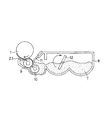
図2を参照して、本実施の形態に係る現像装置の構成について説明する。図2は、本実施の形態における現像装置の概略構成図である。
(Configuration of developing device)
With reference to FIG. 2, the structure of the developing device according to the present embodiment will be described. FIG. 2 is a schematic configuration diagram of the developing device in the present embodiment.
本実施の形態における現像装置3は、非磁性一成分DC接触現像方式によって現像を行う接触一成分現像装置である。かかる現像方式の現像装置3は、現像剤担持体として半導電性(中抵抗:例えば体積抵抗率が109〜1011Ω・cm)の現像ローラ、又は表面に誘電層を形成した現像ローラを用いて、これを感光ドラム1の表面層に押し当てて現像を行うものである。
The developing
現像装置3は、一成分現像剤としての非磁性のトナーTで現像を行う接触一成分現像装置である。現像装置3は、現像剤担持体としての現像ローラ9、現像剤供給部材としての弾性ローラ10、層厚規制部材としての規制ブレード11、攪拌部材12を備えている。
The developing
ここで、現像ローラ9は、現像容器8の開口部に感光ドラム1と対向配置され、図2に示す矢印方向(反時計方向)に回転自在に設けられている。弾性ローラ10は、回転自在であって、現像ローラ9に圧接するように設けられている。
Here, the developing
規制ブレード11は弾性を有し、現像ローラ9に当接するように設けられている。攪拌部材12は、現像容器8内のトナーTを攪拌するように回転可能に設けられている。また、規制ブレード11は、現像ローラ9と弾性ローラ10との圧接部に対して現像ローラ9の回転方向下流側で現像ローラ9に当接している。
The regulating
攪拌部材12で攪拌されたトナーTは、現像ローラ9に圧接して回転する弾性ローラ10によって現像ローラ9表面に供給される。現像ローラ9表面に供給されたトナーTは、現像ローラ9の回転に伴い搬送され、規制ブレード11と現像ローラ9の当接部で摩擦により電荷を付与されて、現像ローラ9表面に薄層化される。
The toner T agitated by the agitating
薄層化されたトナーTは現像ローラ9の回転によって担持搬送され、感光ドラム1との当接部(現像部)にて感光ドラム1上に形成された静電潜像に付着して顕像化する。なお、現像ローラ9上の現像に寄与しなかったトナーTは、弾性ローラ10で剥ぎ取られる。
The thinned toner T is carried and conveyed by the rotation of the developing
更に説明すると、現像ローラ9は、トナーTを収容した現像容器8の長手方向に延在する開口部に位置して、感光ドラム1と対向して配置される。現像ローラ9は、感光ドラム1と所定の当接幅を持って接触し、感光ドラム1の周速(200mm/s)よりも速い周速(300mm/sec)で図2に示す矢印方向(反時計方向)に回転駆動される。本実施の形態では、感光ドラム1と現像ローラ9とは、当接部においてそれぞれの表面移動方向が同方向となるように回転する。
More specifically, the developing
次に、現像ローラ9を駆動する方法の詳細を説明する。
Next, details of a method of driving the developing
現像ローラ9の駆動手段として、本実施の形態ではモーター(不図示)を用いた。また、このモーターで、現像装置内の現像ローラ9、弾性ローラ10、撹拌部材12も回転駆動させた。ただし、感光ドラム1の駆動には、現像ローラ9を駆動するモーターとは別の回転駆動手段を用いる。
In the present embodiment, a motor (not shown) is used as a driving unit for the developing
現像装置3を駆動する際の負荷としては、主に、現像ローラ9と規制ブレード11間の負荷、現像ローラ9と弾性ローラ10間の負荷、現像ローラ9と感光ドラム1間の負荷、現像ローラ9とシール部材23間の負荷、現像容器内の撹拌部材12の回転負荷がある。また、部材間には常にトナーが存在するため、トナーの状態によって負荷は変動する。
The load when driving the developing
本実施の形態におけるトナーの劣化検知は、後に説明するが、現像ローラ9の回転負荷に基づいてトナー劣化を検知するものである。特に、比較例2、比較例3、及び本実施の形態〜第5の実施の形態では、現像ローラ9を回転駆動する負荷を電力で検知する。
As will be described later, the toner deterioration detection in the present embodiment is to detect toner deterioration based on the rotational load of the developing
現像ローラ9の表面は、トナーTとの摺擦確率を高くし、且つ、トナーTの搬送を良好に行うために、適度な凹凸を有している。本実施の形態では、現像ローラ9は、直径16mm、長さ240mmであり、芯金の上に設けられた肉厚4mmのシリコーンゴム層上に、アクリル・ウレタン系の薄層がコートされて構成されている。
The surface of the developing
現像ローラ9には、第1電圧印加手段としての現像バイアス電源が接続されており、本実施の形態では、この現像バイアス電源から現像ローラ9に負極性の所定電位の現像バイアスが印加される。
The developing
現像ローラ9としては、電気抵抗値が104〜106Ω、表面粗さ[算術平均粗さ:JIS中心線平均粗さ(JIS B 0601:2001)]Raが0.3〜5.0μm、硬度がアスカーC硬度で40°〜70℃(加重1kg)に調整されたものが好適である。
The developing
本実施の形態では、電気抵抗105Ω、表面粗さRaが2.0μm、アスカーC硬度が55°の現像ローラ9を用いた。
In the present embodiment, the developing
なお、現像ローラ9の電気抵抗値は、次のようにして測定されたものである。直径30mmのアルミローラ(図示せず)と現像ローラ9とを当接荷重500gf(4.9N)で長手方向全域にて当接させ、このアルミローラを0.5rpsで回転させる。
The electrical resistance value of the developing
そして、現像ローラ9に−400Vの直流電圧を印加して、アース側に10kΩの抵抗を配置する。そして、この抵抗の両端の電圧を測定し、測定された電圧値から電流値を算出して現像ローラ9の抵抗値を算出する。
Then, a DC voltage of −400 V is applied to the developing
また、現像ローラ9と感光ドラム1との当接部(現像部)よりも現像ローラ9の回転方向下流側において、可撓性のシール部材23が設けられている。シール部材23は、未現像トナーTの現像容器8内への通過を許容すると共に、現像容器8内のトナーTが、現像ローラ9と感光ドラム1との当接部よりも現像ローラ9の回転方向下流側から漏出するのを防止する。
Further, a
弾性ローラ10は、規制ブレード11と現像ローラ9との当接部よりも現像ローラ9の回転方向上流側において現像ローラ9に当接し、図2に示す矢印方向(反時計方向)に回転駆動される。
The
弾性ローラ10としては、発泡骨格状スポンジ構造のものが、現像ローラ9へのトナーTの供給及び現像ローラ9からの未現像トナーTの剥ぎ取り性能の点で好ましい。本実施
の形態では、芯金上にポリウレタンフォーム(ポリウレタンから成るスポンジ)を設けた直径16mmの弾性ローラ10を用いた。
The
弾性ローラ10の現像ローラ9に対する当接幅としては、1〜6mmが好ましい。また、弾性ローラ10は、現像ローラ9との当接部において、現像ローラ9に対して相対速度を持たせることが好ましい。本実施の形態では、現像ローラ9との当接幅を2mmに設定した。また、この時の弾性ローラ10と現像ローラ9との当接圧(線圧)は40gf/cm(0.392N/cm)であった。
The contact width of the
また、本実施の形態では、弾性ローラ10は、現像動作時に周速が200mm/secとなるように、駆動手段(図示せず)により所定のタイミングで回転駆動されている。弾性ローラ10と現像ローラ9とは、接触位置においてそれぞれの表面移動方向が逆方向となるように回転する。又、弾性ローラ10の電位と現像ローラ9の電位は等電位である。
In the present embodiment, the
規制ブレード11は弾性を有しており、現像ローラ9と弾性ローラ10との当接部よりも現像ローラ9の回転方向下流側において、その自由端側の先端近傍が現像ローラ9の外周面に面接触にて当接するように設けられている。
The regulating
規制ブレード11は、導電性を有し、バネ弾性を有するSUS又はリン青銅の金属薄板から構成されることが好ましい。シリコーン、ウレタン等のゴム材料や、バネ弾性を有するSUS又はリン青銅の金属薄板を基体として、現像ローラ9への当接面側に導電性ゴム材料等を接着して構成してもよい。
The
本実施の形態では、厚さ0.1mmの板状のリン青銅金属薄板で形成された規制ブレード11を用いた。また、規制ブレード11の現像ローラ9に対する当接圧(線圧)は、本実施の形態では、25gf/cm(0.245N/cm)以上35gf/cm(0.343N/cm)以下に設定した。
In the present embodiment, the
規制ブレード11の現像ローラ9に対する当接方向は、規制ブレード11の自由端側の先端が現像ローラ9との当接部に対して現像ローラ9の回転方向上流側に位置する、所謂、カウンター方向になっている。
The contact direction of the
なお、本実施の形態において、線圧は次のようにして測定したものである。即ち、摩擦係数が既知の金属薄板を3枚当接部に挿入し、その中央の1枚をばね計りで引き抜いた時の値から線圧を換算した。 In the present embodiment, the linear pressure is measured as follows. That is, the linear pressure was converted from the value when three thin metal plates having a known friction coefficient were inserted into the abutting portion, and the central one was pulled out by a spring gauge.
また、規制ブレード11に電圧を印加することで、規制ブレードニップに電界を形成することができる。ここで、規制ブレード11に印加する電圧をVb、現像ローラ9に印加する電圧をVdevとし、ΔVbを次のように定義する。
定義式:ΔVb=Vb−Vdev
Moreover, an electric field can be formed in the regulating blade nip by applying a voltage to the
Definition formula: ΔVb = Vb−Vdev
この定義によると、例えばΔVbが正極性の場合、規制ブレードニップにおいて、負極性に帯電したトナーを、規制ブレード11側に引き付ける電界が形成される。
According to this definition, for example, when ΔVb is positive, an electric field that attracts negatively charged toner toward the
逆に、ΔVbが負極性の場合、規制ブレードニップにおいて、負極性に帯電したトナーを、現像ローラ9側に引き付ける電界が形成される。本実施の形態中では、ΔVb=−200Vに設定した。
On the other hand, when ΔVb is negative, an electric field that attracts negatively charged toner toward the developing
現像動作時には、現像容器8内のトナーTは、攪拌部材12の図2に示す矢印方向(時計方向)の回転に伴い弾性ローラ10側に送られる。このトナーTは、弾性ローラ10の
図2に示す矢印方向(反時計方向)の回転によって、現像ローラ9の近傍に搬送される。弾性ローラ10上に担持されているトナーTは、現像ローラ9と弾性ローラ10との当接部において現像ローラ9と摺擦されることによって摩擦帯電を受け、現像ローラ9上に付着する。
During the developing operation, the toner T in the developing
そして、現像ローラ9の図2に示す矢印方向(反時計方向)の回転に伴い、トナーTが規制ブレード11の圧接下に送られ、現像ローラ9上で薄層化され、感光ドラム1との対向部である現像部へ搬送される。本実施の形態では、トナーTの良好な帯電電荷量は、−40〜−70mC/kgとなるように設定されている。
Then, as the developing
現像ローラ9上(現像剤担持体上)に薄層形成されたトナーTは、現像ローラ9に−300Vの現像バイアスが印加されることによって、現像部において感光ドラム1上に形成されている静電潜像に付着する。これにより、感光ドラム1上の静電潜像は、トナー像として現像される。
The toner T formed in a thin layer on the developing roller 9 (on the developer carrying member) is statically formed on the
また、現像ローラ9上の現像に寄与しなかったトナーTは、弾性ローラ10との当接部において現像ローラ9の表面から剥ぎ取られる。この剥ぎ取られたトナーTの大部分は、弾性ローラ10の回転に伴って搬送され、現像容器8内のトナーTと混ざり合い、トナーTの帯電電荷が分散される。そして、同時に弾性ローラ10の回転により現像ローラ9上に新たなトナーTが供給され、上述した現像動作が繰り返される。
The toner T that has not contributed to the development on the developing
(一成分現像剤についての説明)
次に、本実施の形態で用いられる一成分現像剤としてのトナーTについて説明する。
(Explanation about one-component developer)
Next, the toner T as a one-component developer used in the present embodiment will be described.
本実施の形態では、体積平均粒径が4.0μm以上10.0μm以下であり、平均円形度が0.950以上のトナーが用いられる。 In the present embodiment, a toner having a volume average particle diameter of 4.0 μm or more and 10.0 μm or less and an average circularity of 0.950 or more is used.
本実施の形態のトナーの体積平均粒径が4μm未満である場合にはトナー粒子の流動性が悪化することによる帯電性が不均一になり易く、例えば、高湿環境下において画像かぶりが発生し易くなるためことが懸念される。また、トナーの体積平均粒径が10μmを超える場合には高精細な出力が困難となり、要求される画質を満足できなくなることが懸念される。 When the volume average particle size of the toner of the present embodiment is less than 4 μm, the chargeability due to the deterioration of the fluidity of the toner particles tends to be non-uniform, for example, image fogging occurs in a high humidity environment. There is concern that it will be easier. Further, when the volume average particle diameter of the toner exceeds 10 μm, high-definition output becomes difficult, and there is a concern that the required image quality cannot be satisfied.
トナーTの体積平均粒径の測定には、例えばコールターカウンターTA−II型、又はコールターマルチサイザーII(ベックマン・コールター株式会社製)等を用いている。これらに個数分布、体積分布を出力するインターフェース(日科機バイオス株式会社製)及びパーソナルコンピュータを接続した測定装置でトナーTの体積平均粒径を測定することができる。この測定では電解液が用いられるが、この電解液には、例えば1級塩化ナトリウムを用いて調製された1%NaCl水溶液や、ISOTON R−II(コールターサイエンティフィックジャパン株式会社製)が使用できる。 For example, a Coulter Counter TA-II type or Coulter Multisizer II (manufactured by Beckman Coulter, Inc.) is used for measuring the volume average particle diameter of the toner T. The volume average particle diameter of the toner T can be measured with a measuring device in which an interface (manufactured by Nikka Ki Bios Co., Ltd.) for outputting the number distribution and volume distribution and a personal computer are connected. In this measurement, an electrolytic solution is used. For this electrolytic solution, for example, a 1% NaCl aqueous solution prepared using primary sodium chloride or ISOTON R-II (manufactured by Coulter Scientific Japan Co., Ltd.) can be used. .
測定法としては、前記電解水溶液100〜150ml中に分散剤として界面活性剤(好ましくはアルキルベンゼンスルホン酸塩)を0.1〜5ml加え、更に測定試料を2〜20mg加える。試料を懸濁した電解液は超音波分散器で約1分間分散処理を行い、アパーチャーとして100μmアパーチャーを用いて、前記コールターカウンターTA−II型により2μm以上のトナーの体積を測定して体積分布を算出する。それから、本実施の形態の体積分布から求めた体積平均粒径を求める。 As a measuring method, 0.1 to 5 ml of a surfactant (preferably alkylbenzene sulfonate) is added as a dispersant to 100 to 150 ml of the aqueous electrolytic solution, and 2 to 20 mg of a measurement sample is further added. The electrolytic solution in which the sample is suspended is dispersed for about 1 minute with an ultrasonic disperser, and the volume distribution is determined by measuring the volume of toner of 2 μm or more with the Coulter Counter TA-II type using an aperture of 100 μm as an aperture. calculate. Then, the volume average particle diameter obtained from the volume distribution of the present embodiment is obtained.
本実施の形態のトナーにおける形状制御は、フロー式粒子像測定装置で計測されるトナーの個数基準の相当径−円形度スキャッタグラムにおける該トナーの平均円形度が0.9
50以上の範囲が好ましい。
The shape control of the toner according to the present embodiment is such that the average circularity of the toner in the equivalent diameter-circularity scattergram based on the number of toners measured by the flow type particle image measuring device is 0.9.
A range of 50 or more is preferred.
トナーの平均円形度が0.950未満のトナーとは、形状が球形から離れて不定形に近づいたトナーを意味する。このような不定形トナーは、現像中に現像器内でトナーが破砕され易いために、粒度分布が変動したり、帯電量分布がブロードになったりするため、その結果、画像濃度低下やかぶりの増加といった現像上不都合な現象を生じ易くなるため好ましくない。 A toner having an average circularity of less than 0.950 means a toner whose shape has moved away from a spherical shape and has approached an indeterminate shape. Such irregular shaped toner tends to be crushed in the developing device during development, so that the particle size distribution fluctuates or the charge amount distribution becomes broad. This is not preferable because an undesired phenomenon such as an increase tends to occur.
本実施の形態におけるトナーTの円形度とは、トナー粒子の形状を定量的に表現する簡便な方法として用いたものである。本実施の形態では、フロー式粒子像測定装置FPIA−1000型(東亜医用電子(現シスメックス)株式会社製)を用いて測定を行い、下式を用いて算出した。なお、測定条件としては、測定時のトナー粒子濃度が5000〜15000個/μlとなるように調整し、トナー粒子を1000個以上計測することで行った。
定義式:円形度=(粒子投影面積と同じ面積の円の周囲長)/(粒子投影像の周囲長)
The circularity of the toner T in the present embodiment is used as a simple method for quantitatively expressing the shape of the toner particles. In the present embodiment, measurement was performed using a flow type particle image measurement device FPIA-1000 (manufactured by Toa Medical Electronics (currently Sysmex) Co., Ltd.), and the calculation was performed using the following formula. The measurement conditions were such that the toner particle concentration at the time of measurement was adjusted to 5000 to 15000 particles / μl, and 1000 or more toner particles were measured.
Definition formula: Circularity = (perimeter of a circle having the same area as the particle projection area) / (perimeter of the particle projection image)
上記式において、「粒子投影面積」とは、二値化されたトナー粒子像の面積であり、「粒子投影像の周囲長」とは、該トナー粒子像のエッジ点を結んで得られる輪郭線の長さと定義する。 In the above formula, the “particle projected area” is the area of the binarized toner particle image, and the “peripheral length of the particle projected image” is the contour line obtained by connecting the edge points of the toner particle image. Is defined as the length of
具体的な測定方法としては、容器中に予め不純固形物等を除去したイオン交換水10mlを用意し、その中に分散剤として界面活性剤、好ましくはアルキルベンゼンスルホン酸塩を加えた後、更に測定試料約0.02gを加え、均一に分散させる。 As a specific measurement method, 10 ml of ion-exchanged water from which impure solids and the like are previously removed is prepared in a container, and a surfactant, preferably an alkylbenzene sulfonate, is added as a dispersant therein, and then further measurement is performed. Add about 0.02 g of sample and disperse uniformly.
分散させる手段としては、超音波分散機UH−50型(株式会社エスエムテー製)に振動子としてφ5mmのチタン合金チップを装着したものを用い、分散の条件としては5分間処理で行い、測定用の分散液とする。 As a means to disperse, an ultrasonic disperser UH-50 type (manufactured by SMT Co., Ltd.) equipped with a titanium alloy tip of φ5 mm as a vibrator is used. A dispersion is obtained.
本実施の形態の体積平均粒径、平均円形度を本発明の好ましい範囲にするための達成手段としては、いわゆる粉砕方法による製造方法の他に、次のような方法等を用いてトナーを製造することも可能である。それは、特開昭36−10231号公報、特開昭59−53856号公報に開示されている懸濁重合方法を用いて直接トナーを生成する方法や、単量体には可溶で得られる重合体が不溶な水系有機溶剤を用い直接トナーを生成する分散重合方法である。また、水溶性極性重合開始剤存在下で直接重合しトナーを生成するソープフリー重合方法に代表される乳化重合方法である。 As means for achieving the volume average particle diameter and average circularity of the present embodiment within the preferred ranges of the present invention, in addition to the production method by the so-called pulverization method, toner is produced using the following method, etc. It is also possible to do. That is, a method of directly producing toner using the suspension polymerization method disclosed in JP-A-36-10231 and JP-A-59-53856, or a heavy polymer that is soluble in a monomer. This is a dispersion polymerization method in which a toner is directly produced using a water-based organic solvent in which the coalescence is insoluble. Further, it is an emulsion polymerization method represented by a soap-free polymerization method in which a toner is produced by direct polymerization in the presence of a water-soluble polar polymerization initiator.
本実施の形態では、トナーの形状を容易にコントロールでき、比較的容易に粒度分布がシャープで体積平均粒径が4〜10μmの微粒子トナーが得られる常圧下での、又は加圧下での懸濁重合方法を用いた。そして、モノマーとしてスチレンとn−ブチルアクリレート、荷電制御剤としてサリチル酸金属化合物、極性レジンとして飽和ポリエステル、更にワックスと着色剤を加え、着色懸濁粒子を製造した。このトナー粒子の体積平均粒径は、6.5μmであり、平均円形度は0.980である。 In this embodiment, the shape of the toner can be easily controlled, and a suspension under normal pressure or under pressure where a fine particle toner having a sharp particle size distribution and a volume average particle size of 4 to 10 μm can be obtained relatively easily. A polymerization method was used. Then, styrene and n-butyl acrylate as monomers, a salicylic acid metal compound as a charge control agent, a saturated polyester as a polar resin, and a wax and a colorant were added to produce colored suspended particles. The toner particles have a volume average particle diameter of 6.5 μm and an average circularity of 0.980.
続いて、本実施の形態の特徴である現像剤母体粒子(以下、トナー母体粒子)に付着させる外添剤について以下に説明する。 Next, the external additive attached to the developer base particles (hereinafter, toner base particles), which is a feature of the present embodiment, will be described below.
本実施の形態では、平均一次粒径が5nm以上100nm未満であるシリカ微粒子が、トナー母体粒子100質量部(現像剤母体粒子100質量部)に対し、1.0質量部以上3.0質量部未満外添されている。かつ、平均一次粒径が5nm以上500nm未満であるシリカ以外の微粒子が、トナー母体粒子100質量部に対し、0.5質量部未満外添さ
れている。
In the present embodiment, silica fine particles having an average primary particle size of 5 nm or more and less than 100 nm are 1.0 part by mass or more and 3.0 parts by mass with respect to 100 parts by mass of toner base particles (100 parts by mass of developer base particles). Less than externally added. Further, fine particles other than silica having an average primary particle size of 5 nm or more and less than 500 nm are externally added in an amount of less than 0.5 parts by mass with respect to 100 parts by mass of the toner base particles.
平均一次粒径が5nm以上100nm未満であるシリカ微粒子が外添されていない場合には、良好なトナーの流動性が得られず、トナー粒子への帯電付与が十分に行われにくくなることが懸念される。良好なトナーの流動性が得られず、トナー粒子への帯電付与が十分に行われない場合には、かぶりの増大、画像濃度の低下、トナー飛散等の問題が発生しやすいことが懸念される。 If silica fine particles having an average primary particle size of 5 nm or more and less than 100 nm are not externally added, there is a concern that good toner fluidity cannot be obtained, and it becomes difficult to sufficiently charge the toner particles. Is done. If good toner fluidity cannot be obtained, and toner particles are not sufficiently charged, there is a concern that problems such as increased fog, decreased image density, and toner scattering are likely to occur. .
平均一次粒径が5nm以上100nm未満であるシリカ微粒子をトナー母体粒子100質量部に対し、1.0質量部未満外添させる場合、現像器を長期間に渡って使用する場合には、現像器の使用後半時に、良好なトナーの流動性が得られないことが懸念される。 In the case where silica fine particles having an average primary particle size of 5 nm or more and less than 100 nm are externally added to less than 1.0 part by mass with respect to 100 parts by mass of the toner base particles, There is a concern that good toner fluidity cannot be obtained in the latter half of use.
このような場合、トナー粒子への帯電付与が十分に行われにくくなることが懸念される。トナー粒子への帯電付与が十分に行われない場合には、かぶりの増大、画像濃度の低下、トナー飛散等の問題が発生しやすい。 In such a case, there is a concern that it is difficult to sufficiently charge the toner particles. If the toner particles are not sufficiently charged, problems such as an increase in fog, a decrease in image density, and toner scattering are likely to occur.
また、平均一次粒径が5nm以上100nm未満であるシリカ微粒子をトナー母体粒子100質量部に対し、3.0質量部以上外添させる場合、感光体表面や現像剤担持体表面へのシリカ汚染が生じやすくなることが懸念される。 In addition, when silica fine particles having an average primary particle size of 5 nm or more and less than 100 nm are externally added to 100 parts by mass of the toner base particles, silica contamination on the surface of the photoreceptor or the developer carrying member is caused. There is a concern that it is likely to occur.
感光体表面や現像剤担持体表面へのシリカ汚染が生じた場合には、画像の連続印字において、感光体表面への融着や現像剤担持体の下層汚染が生じることにより、現像弊害を生じることが懸念される。 When silica contamination occurs on the surface of the photosensitive member or the developer carrying member, it causes development problems due to fusion to the surface of the photosensitive member or contamination of the lower layer of the developer carrying member in continuous printing of images. There is concern.
このように、平均一次粒径が5nm以上100nm未満であるシリカ微粒子が、トナー母体粒子100質量部に対し、1.0質量部以上3.0質量部未満外添されていることで、良好なトナーの流動性を得ることができる。したがって、トナー粒子への帯電付与を十分に行うことができる。 As described above, the silica fine particles having an average primary particle diameter of 5 nm or more and less than 100 nm are externally added to 1.0 part by mass or more and less than 3.0 parts by mass with respect to 100 parts by mass of the toner base particles. The fluidity of the toner can be obtained. Therefore, it is possible to sufficiently charge the toner particles.
ここで、現像、転写、定着、クリーニングの各プロセスの性能を維持するために、他の微粒子を少量外添して、トナーの流動性及び帯電性を微調整しても良い。 Here, in order to maintain the performance of each process of development, transfer, fixing, and cleaning, a small amount of other fine particles may be externally added to finely adjust the fluidity and chargeability of the toner.
ただし、微粒子の平均一次粒径が500nm以上であるとトナー表面から脱離し易いため、トナーの流動性及び帯電性を長期間維持することが困難となるので、平均一次粒径が5nm以上500nm未満である微粒子を外添することが好ましい。 However, if the average primary particle size of the fine particles is 500 nm or more, it is easy to detach from the toner surface, and it becomes difficult to maintain the fluidity and chargeability of the toner for a long period of time, so the average primary particle size is 5 nm or more and less than 500 nm. It is preferable to externally add the fine particles.
また、平均一次粒径が5nm未満である微粒子が外添されている場合には、微粒子の凝集性が強まり、一次粒子ではなく解砕処理によっても解れ難い強固な凝集性を持つ粒度分布の広い凝集体として挙動し易い。このため、凝集体の現像や、定着部材あるいは像担持体或いは現像剤担持体等を傷つけるなどによる画像欠陥を生じ易くなることが懸念される。 In addition, when fine particles having an average primary particle size of less than 5 nm are externally added, the fine particles have a high cohesive property and have a wide particle size distribution having a strong cohesive property that is difficult to break even by crushing treatment instead of the primary particles. It tends to behave as an aggregate. For this reason, there is a concern that image defects are likely to occur due to development of the aggregate, damage to the fixing member, the image carrier, or the developer carrier.
通常、平均一次粒径が5nm以上500nm未満である微粒子を、トナー母体粒子100質量部に対し、0.5質量部未満外添される程度ならば、平均一次粒径が5nm以上100nm未満であるシリカ微粒子の効果が大きい。このため、良好なトナーの流動性及び帯電性を得ることができる。これにより、十分に良好な画像を出力することができる。 Usually, the average primary particle size is 5 nm or more and less than 100 nm if fine particles having an average primary particle size of 5 nm or more and less than 500 nm are externally added to less than 0.5 parts by mass with respect to 100 parts by mass of the toner base particles. The effect of silica fine particles is great. Therefore, good toner fluidity and chargeability can be obtained. Thereby, a sufficiently good image can be output.
平均一次粒径が5nm以上500nm未満である微粒子としては、次のようなものを例示することができる。例えば、テフロン(登録商標)粉末、ステアリン酸亜鉛粉末、ポリフッ化ビニリデン粉末の如き滑剤粉末である。さらに、酸化セリウム粉末、炭化硅素粉末
、チタン酸ストロンチウム粉末などの研磨剤を用いてもよい。
Examples of the fine particles having an average primary particle size of 5 nm or more and less than 500 nm include the following. For example, lubricant powders such as Teflon (registered trademark) powder, zinc stearate powder, and polyvinylidene fluoride powder. Furthermore, abrasives such as cerium oxide powder, silicon carbide powder, and strontium titanate powder may be used.
さらに、酸化チタン粉末、酸化アルミニウム粉末などの流動性付与剤や、ケーキング防止剤、球状シリカ粒子、球状ポリメチルシルセスキオキサン粒子、球状樹脂粒子等の無機又は有機の球状に近い微粒子などのクリーニング助剤を用いてもよい。また、逆極性の有機微粒子、及び無機微粒子を現像性向上剤として少量用いることもできる。これらの添加剤も表面を疎水化処理して用いることが可能である。 In addition, fluidity-imparting agents such as titanium oxide powder and aluminum oxide powder, cleaning of anti-caking agents, spherical silica particles, spherical polymethylsilsesquioxane particles, spherical resin particles, and other inorganic or organic spherical particles. An auxiliary agent may be used. In addition, organic fine particles having opposite polarity and inorganic fine particles can be used in small amounts as a developability improver. These additives can also be used after hydrophobizing the surface.
本実施の形態における、外添剤微粒子の平均一次粒径の測定法を次に示す。 A method for measuring the average primary particle size of the external additive fine particles in the present embodiment will be described below.
測定にあたっては、走査型電子顕微鏡により拡大撮影したトナーの写真で、更に走査型電子顕微鏡に付属させたXMA等の元素分析手段によって外添剤微粒子の含有する元素でマッピングされたトナーの写真を対照して行われる。そして、これらの写真を対照しつつ、トナー表面に付着或いは遊離して存在している外添剤微粒子の一次粒子を100個以上測定し、個数平均粒径を求めることで、平均一次粒径を測定する。 In the measurement, a photograph of the toner magnified with a scanning electron microscope is used, and a photograph of the toner mapped with the elements contained in the external additive fine particles is further contrasted by an elemental analysis means such as XMA attached to the scanning electron microscope. Done. Then, while contrasting these photographs, 100 or more primary particles of the external additive fine particles adhering to or liberating from the toner surface were measured, and the number average particle diameter was determined to obtain the average primary particle diameter. taking measurement.
シリカ微粒子は、疎水化処理されていることが好ましい。例えば、シリカ微粒子の表面をシリコーンオイル処理することで、疎水化処理できる。 The silica fine particles are preferably hydrophobized. For example, the surface of silica fine particles can be hydrophobized by treating with silicone oil.
また、シリカ微粒子は、一般にトナーの流動性改良及びトナー母体粒子の帯電均一化のために添加されるが、無機微粒子を本実施の形態のようにシリコーンオイルによって疎水化処理することにより、次のような機能を付与することができる。それは、トナーの帯電量の調整、環境安定性だけでなく、本実施の形態の定着ベルトに対する離型性の向上等の機能である。 Silica fine particles are generally added to improve the fluidity of the toner and make the toner base particles uniformly charged. By treating the inorganic fine particles with a silicone oil as in the present embodiment, the following treatment is performed. Such a function can be provided. The functions include not only adjustment of toner charge amount and environmental stability, but also improvement of releasability from the fixing belt of the present embodiment.
なお、シリカ微粒子を疎水化処理したものが高湿環境下でもトナー粒子の帯電量を高く維持し、トナー飛散を防止する上でより好ましい。 It is more preferable that the silica fine particles are hydrophobized in order to keep the charge amount of the toner particles high even in a high-humidity environment and to prevent toner scattering.
本実施の形態では、トナー母体粒子100質量部に対して、平均一次粒径10nmのシリカAを1.5質量部、平均一次粒径50nmのシリカBを0.4質量部計量し、ヘンシェルミキサーで乾式混合した。なお、これは後述の第2〜第5の実施の形態、及び比較例においても同様である。 In the present embodiment, 1.5 parts by mass of silica A having an average primary particle diameter of 10 nm and 0.4 parts by mass of silica B having an average primary particle diameter of 50 nm are measured with respect to 100 parts by mass of toner base particles. And dry mixed. This also applies to second to fifth embodiments described later and comparative examples.
このトナーTのトナー体積抵抗値としては1014Ω・cm以上である。トナーTの体積抵抗値の測定条件は、直径φ:6mm、測定電極板面積:0.283cm2、圧力:1500gの錘を用い、圧力:96.1kPa、測定時の粉体層厚:0.5〜1.0mmとした。そして、400Vの直流電圧を微小電流計(YHP(横河ヒューレットパッカード株式会社製)4140pA METER/DC VOLTAGE SOUCE)で電流値を測定し、測定した電流値より体積抵抗値(比抵抗)を算出する。 The toner volume resistance value of the toner T is 10 14 Ω · cm or more. The measurement conditions of the volume resistance value of the toner T are: diameter φ: 6 mm, measurement electrode plate area: 0.283 cm 2 , pressure: weight of 1500 g, pressure: 96.1 kPa, powder layer thickness at measurement: 0.00. It was 5-1.0 mm. Then, a 400 V DC voltage is measured with a microammeter (YHP (Yokogawa Hewlett-Packard Co., Ltd.) 4140 pA METER / DC VOLTAGE SOUCE), and a volume resistance value (specific resistance) is calculated from the measured current value. .
本実施の形態においては、トナー結着樹脂のガラス転移温度(Tg)は、40〜70℃であることがよい。Tgが40℃未満の場合にはトナーの保存安定性や耐久安定性の面から問題が生じやすく、70℃を超える場合にはトナーの定着点の上昇をもたらす。 In the present embodiment, the glass transition temperature (Tg) of the toner binder resin is preferably 40 to 70 ° C. When Tg is less than 40 ° C., problems are likely to occur from the viewpoint of storage stability and durability stability of the toner, and when it exceeds 70 ° C., the fixing point of the toner is increased.
フルカラー画像を形成するためのカラートナーの場合においては各色トナーの定着時の混色性が低下し色再現性にやや劣り、OHP画像の透明性が低下する。特に、45〜65℃であることが好ましい。本実施の形態では、Tgが60℃のトナーを用いた。 In the case of a color toner for forming a full-color image, the color mixing property at the time of fixing each color toner is lowered, the color reproducibility is slightly inferior, and the transparency of the OHP image is lowered. In particular, the temperature is preferably 45 to 65 ° C. In the present embodiment, toner having a Tg of 60 ° C. is used.
トナーに含まれるワックスの最大吸熱ピークは、45〜75℃であることが好ましい。ワックスの最大吸熱ピークが45℃未満の場合、本実施の形態に用いられる樹脂のガラス
転移温度よりも低くなるために、高温環境に放置した際にトナー表面に溶け出すため、耐ブロッキング性能が大幅に悪くなることが懸念される。
The maximum endothermic peak of the wax contained in the toner is preferably 45 to 75 ° C. When the maximum endothermic peak of the wax is lower than 45 ° C., it becomes lower than the glass transition temperature of the resin used in the present embodiment, so that it dissolves on the toner surface when left in a high temperature environment, so that the anti-blocking performance is greatly improved. There is concern about getting worse.
一方、最大吸熱ピークが75℃より大きい場合、トナー定着溶融時にワックスが迅速に溶融トナー表面に移行できず、離型性が悪くなるために、高温オフセットが発生し易くなることが懸念される。特に、50〜70℃であることが好ましい。本実施の形態では、最大吸熱ピークが65℃のトナーを用いた。 On the other hand, if the maximum endothermic peak is greater than 75 ° C., the wax cannot quickly move to the surface of the molten toner during toner fixing and melting, and the releasability deteriorates, so that high temperature offset is likely to occur. In particular, the temperature is preferably 50 to 70 ° C. In this embodiment, toner having a maximum endothermic peak of 65 ° C. is used.
なお、本実施の形態において、Tgの測定には、例えばパーキンエルマー社製示差走査熱量計「DSC−7」を用いて、ASTM D3418−82に準じて測定する。装置検出部の温度補正はインジウムと亜鉛の融点を用い、熱量の補正についてはインジウムの融解熱を用いる。測定試料は2〜10mg、好ましくは5mgを精密に秤量する。測定試料はアルミニウム製パンを用い対照用に空パンをセットし、測定温度範囲30〜200℃の間で、昇温速度10℃/minで常温常湿下測定を行う。2回目の昇温過程で得られる、温度30〜200℃の範囲におけるDSC(示差走査熱量測定)曲線をもって解析を行う。 In the present embodiment, Tg is measured according to ASTM D3418-82 using, for example, a differential scanning calorimeter “DSC-7” manufactured by PerkinElmer. The temperature correction of the device detection unit uses the melting points of indium and zinc, and the correction of heat uses the heat of fusion of indium. The measurement sample is precisely weighed in an amount of 2 to 10 mg, preferably 5 mg. As the measurement sample, an aluminum pan is used and an empty pan is set for control, and measurement is performed at room temperature and normal humidity at a temperature increase rate of 10 ° C./min within a measurement temperature range of 30 to 200 ° C. Analysis is performed with a DSC (Differential Scanning Calorimetry) curve in the temperature range of 30 to 200 ° C. obtained in the second temperature raising process.
ガラス転移温度(Tg)については、得られたDSC曲線より中点法で解析を行った値を用いる。また、ワックスの融点ついては、得られたDSC曲線の吸熱メインピークの温度値を用いる。 As for the glass transition temperature (Tg), a value obtained by analyzing by the midpoint method from the obtained DSC curve is used. For the melting point of the wax, the temperature value of the endothermic main peak of the obtained DSC curve is used.
(トナー劣化検知方法の原理)
本実施の形態におけるトナー劣化検知方法の原理を説明する。
(Principle of toner deterioration detection method)
The principle of the toner deterioration detection method in the present embodiment will be described.
現像ローラ9の駆動電力の検知は、感光ドラム1にトナーが現像されていない非画像形成時に行う。本実施の形態では、現像ローラ表面周速V1は300[mm/s]、感光ドラム表面周速V2は200[mm/s]で回転している。回転方向は現像部において同一方向であり、周速差V1−V2は100[mm/s]で、現像ローラ9の方が速く回転する。
The detection of the driving power of the developing
現像部において、現像ローラ9と感光ドラム1はトナーを介して接触している。非画像形成時には、感光ドラム1の表面電位は約−500Vに帯電しており、現像ローラ9の芯金には−300V電圧が印加されている。
In the developing unit, the developing
本実施の形態におけるトナーは負帯電トナーであるので、トナーは現像ローラ9の表面に付着したまま現像部を通過する。すなわち、100[mm/s]の周速差が生じるのは、現像ローラ9上のトナー層と、感光ドラム1表面の間である。
Since the toner in the present embodiment is a negatively charged toner, the toner passes through the developing portion while adhering to the surface of the developing
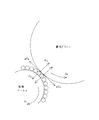
図13に、現像ローラ9と感光ドラム1が当接している時の、現像部における力の釣り合いを示す。また、図14に、現像ローラ9と感光ドラム1が離間している時の、現像部における力の釣り合いを示す。
FIG. 13 shows a balance of forces in the developing portion when the developing
図13では、現像ローラ9と感光ドラム1は当接しており、垂直効力F2が感光ドラム1表面及び、現像ローラ9上のトナー層にかかる。そして、現像ローラ9上のトナー層と、感光ドラム1表面の間には、摩擦力が生じる。この時の動摩擦係数をμとすると、現像ローラ9は回転を妨げる方向に力μF2を受け、反対に感光ドラム1は回転を助ける方向に力μF2を受ける。
In FIG. 13, the developing
これに対して、図14では、現像ローラ9と感光ドラム1は離間しており、現像ローラ9上のトナー層と、感光ドラム1の間には力が働かない。
In contrast, in FIG. 14, the developing
従って、感光ドラム1と現像ローラ9の当接時は、両者が離間している時と比較すると、現像ローラ9が感光ドラム1と摺擦することにより、μF2×100[mm/s]分余計に駆動電力が必要になる。
Accordingly, when the
そして、このμF2×100[mm/s]は、現像ローラ9と感光ドラム1が当接している時の現像ローラ駆動電力と、現像ローラ9と感光ドラム1が離間している時の現像ローラ駆動電力との差分とほぼ同じである。
The μF2 × 100 [mm / s] is the developing roller driving power when the developing
ここで本件の発明者は、現像ローラ9や規制ブレード11にトナー融着が生じる場合は、上記差分が装置本体の使用初期と比べて上昇する事を発見した。
Here, the inventor of the present invention has found that when toner fusing occurs on the developing
これは、現像装置3を使用し続けてもF2は変化しないので、現像ローラ9上のトナー層と、感光ドラム1表面の動摩擦係数μが上昇することを意味する。このように、動摩擦係数μが上昇し、トナーにかかる負荷が大きくなることで、トナー融着が発生しやすくなる。
This means that even if the developing
また、さらに、動摩擦係数μに対するトナーや感光ドラム、現像ローラの寄与を明らかにする実験を行った。 Furthermore, an experiment was conducted to clarify the contribution of toner, photosensitive drum, and developing roller to the dynamic friction coefficient μ.
具体的には、長期間使用した現像器内の残留トナー、長期間使用した現像ローラ、長期間使用した感光ドラム、さらに新品トナー、新品現像ローラ、新品感光ドラムによって、各々を組み換えて作成した現像装置を用いた。そして、その現像装置を用いて、現像ローラと感光ドラムが当接している時の現像ローラ駆動電力と、現像ローラと感光ドラムが離間している時の現像ローラ駆動電力との差分を駆動負荷測定手段によって測定した。 Specifically, the development was made by recombining each with residual toner in the developing unit used for a long time, developing roller used for a long time, photosensitive drum used for a long time, new toner, new developing roller, new photosensitive drum. A device was used. Then, using the developing device, a driving load measurement is performed on the difference between the developing roller driving power when the developing roller and the photosensitive drum are in contact with each other and the developing roller driving power when the developing roller and the photosensitive drum are separated from each other. Measured by means.
図15にその測定結果を示す。この図から分かるように、上記差分はトナーによって大きく影響を受け、感光ドラムや現像ローラには小さな影響しか受けないことが分かった。従って、動摩擦係数μはトナーが劣化することにより上昇することが分かった。 FIG. 15 shows the measurement results. As can be seen from the figure, the difference is greatly influenced by the toner, and the photosensitive drum and the developing roller are only slightly affected. Therefore, it was found that the dynamic friction coefficient μ increases as the toner deteriorates.
以上の事実から、現像ローラ9と感光ドラム1が当接している時の現像ローラ駆動電力と、現像ローラ9と感光ドラム1が離間している時の現像ローラ駆動電力との差分を測定することで、トナー劣化を検知することが可能になる。
From the above fact, the difference between the developing roller driving power when the developing
(トナー劣化検知方法の説明)
図8を参照して本実施の形態におけるトナー劣化検知方法について説明する。図8は、本実施の形態におけるトナー劣化情報検知装置の概略構成図である。
(Description of toner deterioration detection method)
With reference to FIG. 8, a toner deterioration detection method in the present embodiment will be described. FIG. 8 is a schematic configuration diagram of the toner deterioration information detection apparatus according to the present embodiment.
図8に示すように、現像ローラ9は現像ローラ駆動モーター51によって回転駆動される。また、トナー劣化情報検知装置(現像剤劣化判定手段)56は、モーター駆動電力検知装置(駆動負荷測定手段)52、検知結果記録装置(測定結果記録手段)53、データ処理装置(データ処理手段)54、データ比較装置55から構成される。すなわち、トナー劣化情報検知装置56は、制御手段、判定手段、記録手段を構成している。
As shown in FIG. 8, the developing
現像装置状態表示装置(不図示)は、現像装置3の状態を表示するが、表示内容はデータ比較装置55によって制御される。
The developing device status display device (not shown) displays the status of the developing
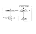
以下、トナー劣化検知の具体的方法を説明する。 Hereinafter, a specific method for toner deterioration detection will be described.
まず、現像装置使用初期における、現像ローラ9と感光ドラム1を当接させた時の駆動
電力と、現像ローラ9と感光ドラム1を離間させた時の駆動電力との差分を基準値W0とする。そして、基準値W0の1.5倍を閾値W1とし、データ比較装置55に記録する。なお、基準値W0の1.5倍を閾値W1とした根拠については後述する。
First, the difference between the driving power when the developing
画像出力前の非画像形成時に、所定時間経過後に、現像ローラ9と感光ドラム1を当接させた状態で、モーター駆動電力検知装置52、検知結果記録装置53、データ処理装置54を用いて、モーター駆動電力を検知する。そして、これらの検知結果を記録して平均値W5を算出する(平均化処理)。算出したW5はデータ比較装置55に記録する。
At the time of non-image formation before image output, the motor driving
同様に、画像出力前の非画像形成時に、所定時間の間、現像ローラ9と感光ドラム1を離間させた状態で、モーター駆動電力検知装置52、検知結果記録装置53、データ処理装置54を用いて、モーター駆動電力を検知する。そして、その検知結果を記録し、その平均値W6を算出する(平均化処理)。算出したW6はデータ比較装置55に記録する。
Similarly, at the time of non-image formation before image output, the motor driving
次に、データ比較装置55を用いて、差分W5−W6と閾値W1の大小関係を比較する。W5−W6<W1(差分が所定の閾値未満である場合)ならば、トナーは劣化していないと判定し、W5−W6≧W1(差分が所定の閾値以上である場合)ならば、トナーは劣化していると判定する。そして、トナー劣化判定を終了する。
Next, using the
このように、現像ローラ9と感光ドラム1の当接時のモーター駆動電力の平均値と、現像ローラ9と感光ドラム1の離間時のモーター駆動電力の平均値との差分を算出すると、測定誤差が小さく、測定結果が安定するため、高精度にトナー劣化を検知できる。
As described above, if the difference between the average value of the motor driving power when the developing
(実使用条件下での耐久試験)
本実施の形態における現像装置3の耐久性能を確認すべく、実使用条件に近い条件下において耐久試験を行った。耐久試験は、現像容器8に、画像印字比率5%のA4サイズの画像8000枚相当である200gのトナーを充填して行った。
(Durability test under actual use conditions)
In order to confirm the durability performance of the developing
評価用の画像は、画像印字比率0.5%、1%、1.5%、2%、3%のA4サイズの文字パターンとした。また、2枚画像出力する毎に1回、5秒停止する間欠モードとした。試験環境は、温度23℃、湿度50%RHとした。 The image for evaluation was an A4 size character pattern with an image printing ratio of 0.5%, 1%, 1.5%, 2%, 3%. In addition, the intermittent mode is set to stop for 5 seconds once every time two images are output. The test environment was a temperature of 23 ° C. and a humidity of 50% RH.
ここで、現像ローラ9、規制ブレード11、弾性ローラ10に印加される電圧をそれぞれ、Vdev、Vb、Vrsとすると、Vdev=−300V、Vb=−500V、Vrs=−300Vに設定し、現像ローラ9回転時は常に同じ電圧を印加し続けた。
Here, when the voltages applied to the developing
現像ローラ9及び規制ブレード11へのトナー融着が発生すると、画像不良である「かぶり」が発生する。この「かぶり」の発生を調べるべく、耐久試験中にかぶり評価を行った。かぶり評価方法は以下の通りである。
When toner fusion to the developing
すなわち、プリントアウト画像の白地部分の白色度(反射率Ds(%))と記録材の白色度(平均反射率Dr(%))との差から、かぶり濃度(%)(=Dr(%)−Ds(%))を算出し、画像かぶりを評価する方法を採用した。ここで、白色度は、「REFLECTMETER MODEL TC−6DS」(有限会社東京電色製)により測定した。 That is, the fog density (%) (= Dr (%)) from the difference between the whiteness (reflectance Ds (%)) of the white background portion of the printout image and the whiteness (average reflectance Dr (%)) of the recording material. -Ds (%)) was calculated, and a method for evaluating image fogging was adopted. Here, the whiteness was measured by “REFLECTMETER MODEL TC-6DS” (manufactured by Tokyo Denshoku Co., Ltd.).
本実施の形態では、ブラックトナーを用いているので、測定時に使用するフィルタとしてグリーンのフィルタを用いた。なお、第2の実施の形態から第5の実施の形態で後述する4色フルカラー画像形成装置では、測定時に使用するフィルタとして、シアンの場合はアンバーライト、イエローの場合はブルー、マゼンタ及びブラックの場合はグリーンのフィルタを用いた。また、かぶりの評価は、以下に示す基準で行った。
○:良好 3.0%未満
×:問題あり 3.0%以上
In this embodiment, since black toner is used, a green filter is used as a filter used during measurement. In the four-color full-color image forming apparatus, which will be described later in the second to fifth embodiments, the filters used at the time of measurement are amber light for cyan, blue, magenta, and black for yellow. In this case, a green filter was used. In addition, the evaluation of fogging was performed according to the following criteria.
○: Good Less than 3.0% ×: There is a problem 3.0% or more
各々の画像印字比率条件で、1000枚印字するごとにかぶり評価を行い、かぶり評価が×となるまで耐久試験を行った。表1にかぶり評価(耐久試験評価)の結果を示す。 Under each image printing ratio condition, the fogging evaluation was performed every time 1000 sheets were printed, and the durability test was performed until the fogging evaluation became x. Table 1 shows the results of the fog evaluation (endurance test evaluation).

表1の1行目は、耐久試験の画像印字比率条件を示す。また、表1中の「トナー残量」、「現像ローラ駆動電力」、「当接時の現像ローラ駆動電力と離間時の現像ローラ駆動電力との差分」、「印字枚数」は、かぶり評価が×となり耐久試験を終了した時点における各々の値を示す。そして、このデータをもとに、各種トナー劣化検知方法を決めた。 The first line of Table 1 shows the image printing ratio conditions of the durability test. In Table 1, “remaining toner amount”, “developing roller driving power”, “difference between developing roller driving power at the time of contact and developing roller driving power at the time of separation”, and “number of printed sheets” are evaluated by fogging. Each value at the time when the endurance test was completed is indicated by x. Based on this data, various toner deterioration detection methods were determined.
まず、本実施の形態では、現像装置使用初期において、現像ローラ9と感光ドラム1を当接させた時の駆動電力と、現像ローラ9と感光ドラム1を離間させた時の駆動電力との差分は、2.0[W]であった。
First, in the present embodiment, in the initial stage of use of the developing device, the difference between the driving power when the developing
そこで、基準値W0=2.0[W]とする。表1の結果を考慮すると、上記差分が基準値W0の1.5倍未満ならば、現像ローラ9や規制ブレード11ヘのトナー融着が発生しない。そこで、閾値W1=3.0[W]と設定し、上記差分が閾値W1未満ならば、現像装置3内のトナーは劣化していないと判定し、上記差分が閾値W1以上ならば、現像装置3内のトナーは劣化していると判定した。そして、1000枚印字するごとに、トナー劣化の判定を行った。
Therefore, the reference value W0 = 2.0 [W]. Considering the results in Table 1, if the difference is less than 1.5 times the reference value W0, toner fusion to the developing
次に、比較例1として、画像印字比率に閾値を設けて、トナー劣化を検知する例を挙げる。この比較例1の場合は、画像印字比率が2.0%の時に、画像不良が発生することがなく、現像装置3内のトナーをほぼ全量消費することができた。
Next, as Comparative Example 1, an example in which a threshold value is provided for the image printing ratio to detect toner deterioration will be described. In the case of Comparative Example 1, when the image printing ratio was 2.0%, no image defect occurred, and almost all the toner in the developing
そこで、画像印字比率の閾値=2.0%とする。画像印字比率が2.0%の時に、現像装置3内のトナーをほぼ全量消費することができる印字枚数をXとする。そして、現像装置使用開始からX枚画像出力し終わったら、現像装置3内に劣化トナーが発生したと判定し、現像装置3の使用を停止する。
Therefore, the threshold value of the image printing ratio is set to 2.0%. When the image printing ratio is 2.0%, X is the number of prints that can consume almost the entire amount of toner in the developing
したがって、画像印字比率が2.0%以上のときは、現像装置内のトナーをほぼ全量消費することができるが、画像印字比率が2.0%未満のときは、現像装置3内のトナーを全量消費することができない。
Therefore, when the image printing ratio is 2.0% or more, almost all of the toner in the developing device can be consumed, but when the image printing ratio is less than 2.0%, the toner in the developing
また、比較例2として、現像ローラ駆動電力に閾値を設けてトナー劣化を検知する例を挙げる。この比較例2の場合、現像装置使用初期において、現像ローラ駆動電力は6.3[W]であった。そこで、基準値Y0=6.3[W]とする。 Further, as Comparative Example 2, an example in which toner deterioration is detected by setting a threshold value for the developing roller driving power will be described. In the case of Comparative Example 2, the developing roller driving power was 6.3 [W] in the early stage of using the developing device. Therefore, the reference value Y0 is set to 6.3 [W].
表1の結果を考慮すると、現像ローラ駆動電力が現像装置使用初期の1.3倍未満ならば、現像ローラ9や規制ブレード11ヘのトナー融着が発生しない。そこで、Y0×1.3≒8.2なので、閾値Y1=8.2[W]と設定し、上記差分が閾値Y1未満ならば、
現像装置3内のトナーは劣化していないと判定し、上記差分が閾値Y1以上ならば、現像装置3内のトナーは劣化していると判定した。そして、1000枚印字するごとに、トナー劣化の判定を行った。
Considering the results shown in Table 1, if the developing roller driving power is less than 1.3 times that in the initial stage of using the developing device, toner fusion to the developing
It was determined that the toner in the developing
以上の条件によって、本実施の形態、比較例1、比較例2の各々のトナー劣化検知方法を用いて、トナーが劣化したことを検知するまで耐久試験を継続した。耐久評価方法は、前述と同様で、評価用の画像は、画像印字比率0.5%、1%、1.5%、2%、3%のA4サイズの文字パターンとする。 Under the above conditions, the endurance test was continued until it was detected that the toner deteriorated using the toner deterioration detection methods of the present embodiment, Comparative Example 1 and Comparative Example 2. The durability evaluation method is the same as described above, and the evaluation image is an A4 size character pattern with an image printing ratio of 0.5%, 1%, 1.5%, 2%, and 3%.
表2に、各々のトナー劣化検知方法を用いて、トナー劣化を検知した時点における現像装置内のトナー残量を示す。 Table 2 shows the remaining amount of toner in the developing device when the toner deterioration is detected using each toner deterioration detection method.
いずれの耐久試験評価においても、かぶり評価が×になることは無かった。この結果から、画像印字比率が2.0%以上では、どのトナー劣化検知方法を用いても現像装置3内のトナーのほぼ全量を消費可能であることがわかる。また、画像印字比率が1.5%では、どのトナー劣化検知方法を用いても、トナーが劣化していると検知した後の現像装置3内トナー残量はほぼ同じであることがわかる。
In any endurance test evaluation, the fogging evaluation did not become x. From this result, it can be seen that when the image printing ratio is 2.0% or more, almost any amount of toner in the developing
しかし、画像印字比率が0.5%、1.0%の場合、本実施の形態におけるトナー劣化検知方法を用いることで、比較例1及び比較例2より現像装置3内のトナー残量を減らすことができる。すなわち、本実施の形態を適用することにより、良好な状態で画像形成できる現像装置や現像剤を、無駄に廃棄することを抑えることができる。これは、現像ローラ9と感光ドラム1の摺擦による駆動負荷変化のみを測定することにより、高い精度でトナー劣化を検知できるためである。
However, when the image printing ratio is 0.5% or 1.0%, the toner remaining amount in the developing
以上のことから、本実施の形態を適用することにより、どのような画像印字比率条件で使用した場合でも、画像不良が発生することが無く、かつ、良好な状態で画像形成できる現像装置や現像剤を、無駄に廃棄することを抑えることができる。 From the above, by applying this embodiment, a developing device and a developer that can form an image in a good state without causing an image defect under any image printing ratio condition. It is possible to suppress wasteful disposal of the agent.
なお、表1及び表2の試験環境は、温度23℃、湿度50%RHの環境(以下N/N環境)で行った。
In addition, the test environment of Table 1 and Table 2 was performed in the environment of
さらに、温度15℃、湿度10%RHの環境(以下L/L環境)、温度30℃、湿度80%RHの環境(以下H/H環境)において、本実施の形態のトナー劣化検知方法を適用して耐久試験を実施した。 Further, the toner deterioration detection method according to the present embodiment is applied in an environment having a temperature of 15 ° C. and a humidity of 10% RH (hereinafter referred to as L / L environment) and an environment having a temperature of 30 ° C. and a humidity of 80% RH (hereinafter referred to as H / H environment). The durability test was conducted.
表3に、N/N環境の試験結果を実施例1−1に、L/L環境の試験結果を実施例1−2に、H/H環境の試験結果を実施例1−3に示す。 Table 3 shows the N / N environment test results in Example 1-1, the L / L environment test results in Example 1-2, and the H / H environment test results in Example 1-3.
表3は、トナー劣化を検知した時点における現像装置3内のトナー残量を示す。なお、いずれの耐久試験評価においても、かぶり評価が×になることは無かった。
Table 3 shows the remaining amount of toner in the developing
このようにN/N環境と同様に、L/L環境、H/H環境においても、本実施の形態のトナー劣化検知方法を適用することにより、良好な状態で画像形成できる現像装置や現像剤を、無駄に廃棄することを抑えることができる。 As described above, in the same manner as in the N / N environment, in the L / L environment and the H / H environment, by applying the toner deterioration detection method of the present embodiment, a developing device and a developer that can form an image in a good state Can be prevented from being wasted.
(実使用条件下でのシーケンス制御)
図1を参照して、本実施の形態において、現像ローラ9及び規制ブレード11に劣化トナーが融着することを防止する、実使用条件下のシーケンス制御を説明する。図1は、本実施の形態に係る画像形成装置のトナー劣化検知のシーケンス制御図である。
(Sequence control under actual use conditions)
With reference to FIG. 1, the sequence control under actual use conditions for preventing the deteriorated toner from fusing to the developing
まず、画像出力命令を待機する状態(ステップS1)において画像出力命令を受けると、トナー劣化検知を行う(ステップS2)。その結果、トナー劣化を検知した場合(Yes)はステップS4に進み、検知しなかった場合(No)はステップS3に進み、画像を出力する。 First, when an image output command is received in a state of waiting for an image output command (step S1), toner deterioration is detected (step S2). As a result, if toner deterioration is detected (Yes), the process proceeds to step S4. If not detected (No), the process proceeds to step S3, and an image is output.
ステップS2でトナー劣化を検知した場合(Yes)、現像装置交換要求を表示し、画像形成を一時停止する(ステップS4)。現像装置交換のためには、画像形成装置のドアを開閉しなければならないので、ドアの開閉が検知されるまで待機する(ステップS5)。 When toner deterioration is detected in step S2 (Yes), a developing device replacement request is displayed and image formation is temporarily stopped (step S4). In order to replace the developing device, it is necessary to open and close the door of the image forming apparatus. Therefore, the process waits until the opening and closing of the door is detected (step S5).
ドアの開閉を検知したら、トナー劣化検知を行い(ステップS6)、トナー劣化を検知した場合(Yes)はステップS4に戻り、検知しなかった場合(No)はステップS3に進み、画像を出力する。そして、ステップS3の画像出力が終了したらステップS1の画像出力待機状態に戻る。 If opening / closing of the door is detected, toner deterioration is detected (step S6). If toner deterioration is detected (Yes), the process returns to step S4. If not detected (No), the process proceeds to step S3 and an image is output. . When the image output in step S3 is completed, the process returns to the image output standby state in step S1.
上記のシーケンス制御を実施することで、現像ローラ9及び規制ブレード11に劣化トナーが付着して画像不良が発生する前に、正常な現像装置に交換することができる。これにより、現像ローラ9及び規制ブレード11へのトナー融着に起因した画像不良を防止することが可能になる。
By performing the sequence control described above, it is possible to replace the developing device with a normal developing device before the deteriorated toner adheres to the developing
(本実施の形態の補足説明)
以下、上記で説明した本実施の形態に係る画像形成装置について、補足的に説明を行う。ここでは、(トナー劣化の検知方法に関する補足説明)、(トナー劣化の判定方法に関する補足説明)、(閾値の設定に関する補足説明)、(現像ローラの回転負荷に関する補足説明)、(基準値と閾値の設定方法に関する補足説明)について説明する。さらに、(現像ローラの駆動電力の検知タイミングに関する補足説明)、(補足トナーに関する補足説明)、(現像ローラと感光ドラムの周速比に関する補足説明)、について説明する。
(Supplementary explanation of this embodiment)
Hereinafter, the image forming apparatus according to the present embodiment described above will be supplementarily described. Here, (supplementary explanation on toner deterioration detection method), (supplementary explanation on toner deterioration determination method), (supplementary explanation on threshold setting), (supplementary explanation on rotation load of developing roller), (reference value and threshold value) Supplementary explanation regarding the setting method) will be described. Further, (supplementary explanation regarding the detection timing of the driving power of the developing roller), (supplementary explanation regarding the supplementary toner), and (supplementary explanation regarding the peripheral speed ratio between the developing roller and the photosensitive drum) will be described.
(トナー劣化の検知方法に関する補足説明)
本実施の形態では、現像ローラ9の駆動電力について、現像ローラ9と感光ドラム1が当接している時と、現像ローラ9と感光ドラム1が離間している時との差分を測定することで、トナー劣化を検知したが、本発明の検知方法は必ずしもこの限りではない。
(Supplementary explanation on toner deterioration detection method)
In this embodiment, the driving power of the developing
図13に示すように、現像ローラ駆動モーターと同様に、感光ドラム駆動モーターも、現像ローラ9と感光ドラム1の摺擦の影響を受ける。したがって、感光ドラム1の駆動電力についても、現像ローラ9と感光ドラム1が当接している時と、現像ローラ9と感光ドラム1が離間している時との差分を測定することで、トナー劣化を検知することができる
。
As shown in FIG. 13, like the developing roller driving motor, the photosensitive drum driving motor is also affected by the rubbing between the developing
また、一つのモーター(駆動手段)で現像ローラ9と感光ドラム1を駆動する場合でも、現像ローラ9と感光ドラム1が当接している時と、現像ローラ9と感光ドラム1が離間している時との差分を測定することで、トナー劣化を検知することができる。
Even when the developing
これは、トナーが劣化すると、現像ローラ9と感光ドラム1が当接している時の現像部において、トナー表面の外添剤埋め込みや外添剤遊離が進み、トナー同士の摺擦によっても電力が消費されるためである。
This is because when the toner deteriorates, in the developing portion when the developing
したがって、感光ドラム1または現像ローラ9を回転駆動するモーターの少なくとも一方について、現像ローラ9と感光ドラム1が当接している時と、現像ローラ9と感光ドラム1が離間している時との差分を測定することで、トナー劣化を検知可能である。
Therefore, with respect to at least one of the motor that rotationally drives the
(トナー劣化の判定方法に関する補足説明)
また、本実施の形態では、現像ローラ9と感光ドラム1が当接している時の現像ローラ駆動電力と、現像ローラ9と感光ドラム1が離間している時の現像ローラ駆動電力との差分を測定することで、トナー劣化を検知した。
(Supplementary explanation regarding the method for determining toner deterioration)
In this embodiment, the difference between the developing roller driving power when the developing
しかしながら、本発明におけるトナー劣化の判定方法はこれに限られるものではない。すなわち、駆動電力の差分を算出するのではなく、当接時と離間時の駆動電力比率からトナー劣化を検知してもよい。 However, the toner deterioration determination method in the present invention is not limited to this. That is, instead of calculating the difference in drive power, toner deterioration may be detected from the drive power ratio at the time of contact and separation.
また、本実施の形態では、当接時と離間時の差分が閾値W1未満である場合、トナーは劣化していないと判定し、当接時と離間時の差分が閾値W1以上である場合、トナーは劣化していると判定した。 In the present embodiment, if the difference between the contact time and the separation time is less than the threshold value W1, it is determined that the toner has not deteriorated. If the difference between the contact time and the separation time is equal to or greater than the threshold value W1, It was determined that the toner was deteriorated.
これによると、現像ローラ表面周速V1>感光ドラム表面周速V2ならば、当接時と離
間時の差分が常に正となるので、本実施の形態で説明した判定方法でよい。しかし、現像ローラ表面周速V1<感光ドラム表面周速V2の場合のように、当接時と離間時の差分が負となる可能性もある。
According to this, if the developing roller surface peripheral speed V1> the photosensitive drum surface peripheral speed V2, the difference between the contact time and the separation time is always positive, so the determination method described in this embodiment may be used. However, as in the case where the developing roller surface peripheral speed V1 <the photosensitive drum surface peripheral speed V2, there is a possibility that the difference between the contact time and the separation time becomes negative.
そこで、現像ローラ表面周速V1と感光ドラム表面周速V2の大小関係が変わっても、劣化トナーを正確に判定可能なように、当接時と離間時の差分の絶対値を閾値W1と比較する判定方法であってもよい。すなわち、当接時と離間時の差分の絶対値が閾値W1未満である場合、トナーは劣化していないと判定し、当接時と離間時の差分の絶対値が閾値W1以上である場合、トナーは劣化していると判定した。 Therefore, the absolute value of the difference between contact and separation is compared with the threshold value W1 so that the deteriorated toner can be accurately determined even if the magnitude relationship between the developing roller surface peripheral speed V1 and the photosensitive drum surface peripheral speed V2 changes. The determination method to do may be used. That is, if the absolute value of the difference between the contact time and the separation time is less than the threshold value W1, it is determined that the toner has not deteriorated. If the absolute value of the difference between the contact time and the separation time is equal to or greater than the threshold value W1, It was determined that the toner was deteriorated.
(閾値の設定に関する補足説明)
本実施の形態では閾値を1つ設定したが、本発明における閾値の設定は必ずしもその限りではない。例えば、閾値を2つ設定してもよい。
(Supplementary explanation on threshold setting)
Although one threshold value is set in the present embodiment, the threshold value setting in the present invention is not necessarily limited thereto. For example, two threshold values may be set.
現像装置使用初期において、現像ローラ9と感光ドラム1を当接させた時の駆動電力と、現像ローラ9と感光ドラム1を離間させた時の駆動電力との差分は2.0[W]であった。しかし、上記表1の結果を考慮すると、上記差分が現像装置使用初期の1.5倍未満であるならば、現像ローラ9や規制ブレード11ヘのトナー融着が発生しない。
In the initial stage of use of the developing device, the difference between the driving power when the developing
そこで、現像装置使用初期の1.3倍を第一の閾値、1.5倍を第二の閾値と設定してもよい。すなわち、閾値W3=2.6[W]、閾値W4=3.0[W]と設定し、上記差分が閾値W3未満ならば「現像装置正常」と表示し、上記差分が閾値W3以上W4未満な
らば、「まもなく現像装置交換要求」と表示する。さらに、上記差分が閾値W4以上ならば「現像装置交換要求」と表示し、画像形成を一時停止する。
Thus, 1.3 times the initial use of the developing device may be set as the first threshold value, and 1.5 times may be set as the second threshold value. That is, the threshold value W3 = 2.6 [W] and the threshold value W4 = 3.0 [W] are set. If the difference is less than the threshold value W3, “development apparatus normal” is displayed, and the difference is greater than or equal to the threshold value W3 and less than W4. Then, “Shortly developed device replacement request” is displayed. Further, if the difference is equal to or greater than the threshold value W4, “development device replacement request” is displayed and image formation is temporarily stopped.
これにより「現像装置交換要求」と表示し、画像形成を一時停止する前に、ユーザーが現像装置3を交換する準備ができるので、すぐに現像装置3を新品に交換でき、画像形成装置100が使用できない時間を極力短くすることができる。
As a result, “development device replacement request” is displayed, and the user can prepare to replace the developing
(現像ローラの回転負荷に関する補足説明)
本実施の形態では、現像ローラ9の回転負荷を検知する方法として、現像ローラ9を回転駆動するモーターの駆動電力を検知する方法を採用したが、本発明における現像ローラ9の回転負荷の検知方法は必ずしもこの限りではない。
(Supplementary explanation regarding rotational load of developing roller)
In this embodiment, as a method of detecting the rotational load of the developing
例えば、モーターを駆動する際に必要な電流を検知する方法であってもよい。これにより、モーター電力の検知と同様に、現像ローラ9の回転負荷を検知することができる。また、モーターを駆動する際に必要な駆動トルクを検知する方法であってもよい。
For example, a method of detecting a current necessary for driving a motor may be used. Thereby, the rotation load of the developing
(基準値と閾値の設定方法に関する補足説明)
本実施の形態では、現像装置使用初期において、現像ローラ9と感光ドラム1を当接させた時の駆動電力と、現像ローラ9と感光ドラム1を離間させた時の駆動電力との差分はW0=2.0[W]であった。
(Supplementary explanation on how to set the reference value and threshold)
In this embodiment, in the initial stage of use of the developing device, the difference between the driving power when the developing
上記表1の結果を考慮すると、上記差分が現像装置使用初期の1.5倍未満ならば、現像ローラ9や規制ブレード11ヘのトナー融着が発生しない。そこで、閾値W1=3.0[W]と設定した。しかし、基準値W0及び閾値W1の設定方法はこの限りではない。
Considering the results shown in Table 1, toner fusion to the developing
例えば、複数の現像装置3に対して、現像ローラ9と感光ドラム1を当接させた時の駆動電力と、現像ローラ9と感光ドラム1を離間させた時の駆動電力との差分を算出し、その平均値をW0としてもよい。
For example, the difference between the driving power when the developing
この方法を用いると、製造されてから使用開始されるまでの現像装置3の履歴の影響をほとんど受けず、また、現像ローラ9や規制ブレード11などの現像装置3内各種部材の性能誤差や設定誤差の影響をほとんど受けずに、基準値W0及び閾値W1を設定できる。よって、安定してトナー劣化を検知できる。
When this method is used, it is hardly affected by the history of the developing
また、現像装置3の使用を開始して所定枚数画像出力後ならば、現像ローラ9を回転駆動する負荷が安定する。よって、その時に、現像ローラ9と感光ドラム1を当接させた時の駆動電力と、現像ローラ9と感光ドラム1を離間させた時の駆動電力との差分を算出し、その平均値をW0としてもよい。
Further, after the start of use of the developing
また、閾値W1は基準値W0の1.5倍でなくともよく、各々の現像装置やトナーに対して適切な定数倍を決めればよい。 Further, the threshold value W1 does not have to be 1.5 times the reference value W0, and an appropriate constant multiple may be determined for each developing device and toner.
(現像ローラの駆動電力の検知タイミングに関する補足説明)
本実施の形態では、画像形成前に現像ローラ駆動電力を検知したが、本発明における現像ローラの駆動電力の検知タイミングは必ずしもこの限りではない。すなわち、画像形成前に限らず、非画像形成時ならばどのタイミングで検知を行ってもよい。
(Supplementary explanation regarding detection timing of developing roller drive power)
In this embodiment, the developing roller driving power is detected before image formation, but the detection timing of the developing roller driving power in the present invention is not necessarily limited to this. That is, not only before image formation, but also at any timing as long as non-image formation is performed.
例えば、画像形成動作終了後、非通紙状態で現像ローラ9の駆動が行われる後回転中に、現像ローラ駆動電力の検知を行ってもよい。また、感光ドラム1上で紙間時に相当するタイミングで、現像ローラ駆動電力の検知を行ってもよい。ここで、紙間とは、連続して
画像形成を行った際の、連続して搬送される記録材と記録材の間を意味する。
For example, after the image forming operation is completed, the developing roller driving power may be detected during the rotation after the developing
なお、非画像形成中に現像ローラ駆動電力を検知する理由は以下の通りである。 The reason for detecting the developing roller driving power during non-image formation is as follows.
非画像形成時には、感光ドラム表面電位は約−500Vに帯電しており、現像ローラ9の心金には−300V電圧が印加され、トナーは負帯電トナーであるので、トナーは現像ローラ9の表面に付着したまま現像部を通過する。すなわち、周速差が生じるのは、常に、現像ローラ9上のトナー層と、感光ドラム1表面の間である。したがって、現像ローラ駆動電力は安定する。
At the time of non-image formation, the photosensitive drum surface potential is charged to about −500 V, a −300 V voltage is applied to the core of the developing
しかし、画像形成中には、現像部において現像ローラ9と感光ドラム1の間のトナーは、現像ローラ9に付着し、感光ドラム1にも付着可能である。したがって、現像ローラ9と感光ドラム1間の動摩擦係数μが不安定になり、現像ローラ9と感光ドラム1間の摺擦に伴う駆動電力の増減も不安定になり、現像ローラ駆動電力は安定しない。
However, during image formation, toner between the developing
以上説明したように、安定した現像ローラ駆動電力を検知するためには、非画像形成中に現像ローラ駆動電力を検知することが好ましい。しかし、画像形成中や、現像ローラ9から感光ドラム1にトナーを現像している時に、トナー劣化を検知する検知タイミングであってもよいことはもちろんである。
As described above, in order to detect a stable developing roller driving power, it is preferable to detect the developing roller driving power during non-image formation. However, it is a matter of course that the detection timing for detecting toner deterioration may be used during image formation or when developing toner from the developing
(補給トナーに関する補足説明)
本実施の形態では、補給トナーの正規帯電極性は負極性であるが、本発明における補給トナーはこれに限定されるものではない。負極性に帯電したトナーではなく、正規帯電極性が正極性であるトナーを用いてもよい。その場合は、必要に応じて、帯電ローラ2、現像ローラ9、規制ブレード11、弾性ローラ10等の部材に印加する電圧の極性を変えればよい。
(Supplementary explanation regarding replenishment toner)
In the present embodiment, the regular charging polarity of the replenishment toner is negative, but the replenishment toner in the present invention is not limited to this. Instead of the negatively charged toner, a toner having a normal charging polarity of positive polarity may be used. In that case, what is necessary is just to change the polarity of the voltage applied to members, such as the charging
(現像ローラと感光ドラムの周速比に関する補足説明)
本実施の形態では、現像ローラ周速V2=300[mm/s]、感光ドラム周速V1=200[mm/s]であり、現像ローラ周速/感光ドラム周速(V2/V1)=1.5であるが、本発明における両者の周速比は必ずしもこの限りではない。
(Supplementary explanation on the peripheral speed ratio between the developing roller and the photosensitive drum)
In this embodiment, the developing roller peripheral speed V2 = 300 [mm / s], the photosensitive drum peripheral speed V1 = 200 [mm / s], and the developing roller peripheral speed / photosensitive drum peripheral speed (V2 / V1) = 1. However, the ratio of the peripheral speeds in the present invention is not necessarily limited to this.
図16は、現像ローラ周速/感光ドラム周速に対する、現像ローラ9と感光ドラム1が当接している時の現像ローラ駆動電力と、現像ローラ9と感光ドラム1が離間している時の現像ローラ駆動電力との差分変化を示す図である。
FIG. 16 shows the developing roller driving power when the developing
図16に示すように、現像ローラ周速/感光ドラム周速が、0.95以下または1.05以上ならば、現像ローラ9と感光ドラム1が当接している時の現像ローラ駆動電力と、離間している時の現像ローラ駆動電力の差分を測定することが可能である。
As shown in FIG. 16, when the developing roller peripheral speed / photosensitive drum peripheral speed is 0.95 or less or 1.05 or more, the developing roller driving power when the developing
ただし、現像ローラ周速/感光ドラム周速が、0.95以下の場合、上記差分は負に、1.05以上の場合、上記差分は正になる。したがって、上記差分の絶対値と閾値を比較すれば、トナー劣化を確実に検知することができる。 However, when the developing roller peripheral speed / photosensitive drum peripheral speed is 0.95 or less, the difference is negative, and when it is 1.05 or more, the difference is positive. Therefore, toner deterioration can be reliably detected by comparing the absolute value of the difference with a threshold value.
[第2の実施の形態]
図4を参照して本発明の第2の実施の形態について説明する。
[Second Embodiment]
A second embodiment of the present invention will be described with reference to FIG.
上記第1の実施の形態では、画像形成装置100は単色の画像形成装置であるものとして説明したが、本発明に係る画像形成装置はこれに限定されるものではなく、フルカラー画像を形成可能な画像形成装置であってもよい。
In the first embodiment, the
すなわち、本実施の形態に係る画像形成装置は、電子写真方式を用いて、フルカラー画像などの多色画像を形成可能なカラー画像形成装置である。 That is, the image forming apparatus according to the present embodiment is a color image forming apparatus capable of forming a multicolor image such as a full color image by using an electrophotographic system.
本実施の形態に係る画像形成装置には、各色のトナーに応じた複数の現像装置が設けられており、各々の現像装置には、回転可能な像担持体が設けられる。そして、画像を形成する際には、感光体上に順次に形成された静電潜像を、各々の現像装置において順次現像する。 The image forming apparatus according to the present embodiment is provided with a plurality of developing devices corresponding to the toners of the respective colors, and each developing device is provided with a rotatable image carrier. When forming an image, the electrostatic latent images sequentially formed on the photoconductor are sequentially developed in each developing device.
各々の感光体上に形成されたトナー像は、記録材上に直接転写されるか、又は中間転写体に一旦転写した後に記録材に転写される。この転写の際に、各々のトナー像が重なって転写されることで、記録材、または中間転写ベルト上には所望の色調を有するカラー画像が形成される。 The toner images formed on the respective photoreceptors are directly transferred onto the recording material, or once transferred onto the intermediate transfer member and then transferred onto the recording material. At the time of this transfer, the toner images are transferred in an overlapping manner, whereby a color image having a desired color tone is formed on the recording material or the intermediate transfer belt.
また、単一の感光体に対して、各色トナーごとに現像装置を設け、単一の感光体上に所望の色調を有するトナー像を現像する構成であってもよい。かかる構成で感光体上に現像されたカラー画像は、その後記録材に転写される。 Further, a developing device may be provided for each color toner on a single photoconductor, and a toner image having a desired color tone may be developed on the single photoconductor. The color image developed on the photoreceptor in such a configuration is then transferred to a recording material.
図4に本実施の形態に係る画像形成装置の概略構成を示す。図4に示すように、本実施の形態に係る画像形成装置は、各色トナーに応じた複数の画像形成部を有し、4色フルカラー画像の形成が可能なカラー画像形成装置である。 FIG. 4 shows a schematic configuration of the image forming apparatus according to the present embodiment. As shown in FIG. 4, the image forming apparatus according to the present embodiment is a color image forming apparatus having a plurality of image forming units corresponding to the respective color toners and capable of forming a four-color full-color image.
図4に示すカラー画像形成装置200は、複数の画像形成部として、それぞれシアン、イエロー、マゼンタ、ブラックの各色の画像を形成するための第1、第2、第3、第4の画像形成部を有する。プロセスカートリッジ19A、19B、19C、19Dはそれぞれ、第1、第2、第3、第4の画像形成部に対応する。
A color
各画像形成部の構成及び動作は、用いるトナーの色が異なることを除いて、第1の実施の形態と実質的に同じであるので、それについての説明は省略する。また、以下の説明において特に区別を要しない場合は、いずれかのトナーの色用に設けられた要素であることを表すために図4中符号に与えた添え字A、B、C、Dは省略して総括的に説明する。 Since the configuration and operation of each image forming unit are substantially the same as those in the first embodiment except that the color of the toner used is different, the description thereof is omitted. In the following description, if there is no particular distinction, subscripts A, B, C, and D given to the reference numerals in FIG. 4 are used to indicate elements provided for any of the toner colors. Omitted and will be described in general.
画像形成装置200は、垂直方向に並設された4個の画像形成部にそれぞれ、像担持体としての感光ドラム1を備える。この感光ドラム1は、矢印方向に駆動モーター(不図示)により回転駆動される。
The
感光ドラム1の周囲には、その回転方向に従って順に、帯電ローラ2、露光装置6、現像装置3、静電搬送転写装置18、クリーニングブレード5等が配設されている。また、現像装置3の動作は、第1の実施の形態において説明した図3の画像形成装置100と同様である。帯電ローラ2は、感光ドラム1の表面を均一に帯電する。
Around the
露光装置6は、画像情報に基づきレーザを照射し、感光ドラム1上に静電潜像を形成する。現像装置3は、静電潜像を現像剤像(トナー像)として現像する。静電搬送転写装置18は、感光ドラム1上のトナー像を記録材Pに転写する。クリーニングブレード5は、転写後の感光ドラム1表面に残った転写残トナーを除去する。
The exposure device 6 irradiates a laser based on the image information and forms an electrostatic latent image on the
感光ドラム1、及び、感光ドラム1に作用するプロセス手段としての帯電ローラ2、現像装置3、クリーニングブレード5及び廃トナー収納容器13は一体的にカートリッジ化され、プロセスカートリッジ19を形成している。プロセスカートリッジ19は、画像形成装置200の本体に着脱可能になっている。
The
また、本実施の形態では、各プロセスカートリッジ19A、19B、19C、19Dは全て同一形状を有し、全て同じ構成であるが、その中に内包されるトナーがそれぞれシアン、イエロー、マゼンタ、ブラックである。
In this embodiment, the
そして、全ての感光ドラム1に対向して接するように、循環移動する記録材担持体としての記録材搬送ベルト(静電搬送ベルト)22が配設されている。また、4個の感光ドラム1に対応して、静電搬送ベルト22の内側に当接する転写部材としての転写ローラ4が並接される。
A recording material conveyance belt (electrostatic conveyance belt) 22 as a recording material carrier that circulates and moves is disposed so as to face and contact all the
転写ローラ4は、静電搬送ベルト22を介して感光ドラム1に当接して転写部を形成する。転写ローラ4から静電搬送ベルト22を介して正極性の電荷が記録材Pに印加され、この電荷による電界により、感光ドラム1に接触中の記録材Pに、感光ドラム1上の負極性トナーが転写される。
The transfer roller 4 abuts on the
また、画像形成装置200には、記録材Pに転写された複数のトナー像を定着させる定着器7が設けられる。感光ドラム1上のトナー像を転写した記録材Pは、定着器7を通過する際に熱及び圧力を印加される。これにより、複数色のトナー像が記録材Pの表面に永久定着される。
Further, the
なお、図4に示すカラー画像形成装置200における現像装置3は、上記第1の実施の形態において図2を参照して説明したものと同様であり、トナーとしては、非磁性一成分現像剤が用いられる。しかし、本発明におけるトナーはこれに限定されず、磁性一成分現像剤を用いてもよい。
The developing
次に、現像ローラ9を駆動する方法の詳細を説明する。
Next, details of a method of driving the developing
現像ローラ9の駆動手段として、本実施の形態ではモーター(不図示)を用いた。また、このモーターで現像装置内の現像ローラ9、弾性ローラ10、撹拌部材12も回転駆動する構成とした。
In the present embodiment, a motor (not shown) is used as a driving unit for the developing
ただし、感光ドラム1、静電搬送ベルト22の駆動には、現像ローラ9を駆動するモーターとは別の回転駆動手段を用いる。本実施の形態では、モーターの数を少なくするために、シアン、イエロー、マゼンタ、ブラック各々の現像器を1つのモーターで駆動する構成とした。
However, for the driving of the
次に、トナー劣化検知方法の種類によって、トナーが劣化していると検知した時の現像装置内トナー残量が異なることを示す。 Next, it will be shown that the remaining amount of toner in the developing device differs when the toner is detected to be deteriorated depending on the type of toner deterioration detection method.
まず本実施の形態では、第1の実施の形態1と同様に、現像装置使用初期において、現像ローラ9と感光ドラム1を当接させた時の駆動電力と、現像ローラ9と感光ドラム1を離間させた時の駆動電力との差分は2.0[W]であった。
First, in the present embodiment, as in the first embodiment, the driving power when the developing
そこで、基準値W0=2.0[W]とする。上記表1の結果を考慮すると、上記差分が基準値W0の1.5倍未満ならば、現像ローラ9や規制ブレード11ヘのトナー融着が発生しない。
Therefore, the reference value W0 = 2.0 [W]. Considering the results of Table 1, if the difference is less than 1.5 times the reference value W0, toner fusion to the developing
そこで、閾値W1=3.0[W]と設定し、上記差分が閾値W1未満ならば、現像装置3内のトナーは劣化していないと判定し、上記差分が閾値W1以上ならば、現像装置内のトナーは劣化していると判定した。
Accordingly, the threshold value W1 = 3.0 [W] is set, and if the difference is less than the threshold value W1, it is determined that the toner in the developing
そして、1000枚印字するごとに、シアン、イエロー、マゼンタ、ブラック各々の現像器について、トナー劣化の判定を行った。 Each time 1000 sheets were printed, toner deterioration was determined for each of the cyan, yellow, magenta, and black developing devices.
次に、比較例3(比較例1、2は上記第1の実施の形態、表2を参照)として、現像ローラ駆動電力に閾値を設けて劣化トナーの有無を検知する方法を設定する。 Next, as Comparative Example 3 (Comparative Examples 1 and 2 refer to the first embodiment described above and Table 2), a method is set for detecting the presence or absence of deteriorated toner by providing a threshold value for the developing roller driving power.
現像装置使用初期において、現像ローラ駆動電力は24.9[W]であった。そこで、基準値Y0=24.9[W]とする。上記表1の結果を考慮すると、現像ローラ駆動電力が現像装置使用初期の1.3倍未満ならば、現像ローラ9や規制ブレード11ヘのトナー融着が発生しない。
In the initial stage of use of the developing device, the developing roller driving power was 24.9 [W]. Therefore, the reference value Y0 = 24.9 [W] is set. Considering the results in Table 1 above, if the developing roller driving power is less than 1.3 times that in the initial stage of using the developing device, toner fusion to the developing
そこで、閾値Y1=32.4[W]と設定し、上記差分が閾値Y1未満ならば、現像装置内のトナーは劣化していないと判定し、上記差分が閾値Y1以上ならば、現像装置内のトナーは劣化していると判定した。そして、1000枚印字するごとに、トナー劣化の判定を行った。 Therefore, the threshold value Y1 = 32.4 [W] is set, and if the difference is less than the threshold value Y1, it is determined that the toner in the developing device is not deteriorated. The toner was determined to be deteriorated. Then, every time 1000 sheets were printed, the toner deterioration was determined.
そして、本実施の形態、比較例3のトナー劣化検知方法を用いて、劣化トナーを検知するまで耐久試験を継続した。耐久評価方法は、前述と同様で、評価用の画像は画像印字比率0.5%、1%、1.5%、2%、3%のA4サイズの文字パターンとする。 The durability test was continued until the deteriorated toner was detected using the toner deterioration detection method of the present embodiment and comparative example 3. The durability evaluation method is the same as described above, and the evaluation image is an A4 size character pattern with an image printing ratio of 0.5%, 1%, 1.5%, 2%, and 3%.
表4に、各々のトナー劣化検知方法を用いて、トナー劣化を検知した時点における現像装置内のトナー残量を示す。 Table 4 shows the remaining amount of toner in the developing device when toner deterioration is detected using each toner deterioration detection method.
上記表4において、いずれの耐久試験評価においても、かぶり評価が×になることは無かった。この結果から、画像印字比率が2.0%以上では、どのトナー劣化検知方法を用いても現像装置内のトナーのほぼ全量を消費可能であることがわかる。 In Table 4 above, in any of the durability test evaluations, the fogging evaluation did not become x. From this result, it can be seen that when the image printing ratio is 2.0% or more, almost any amount of toner in the developing device can be consumed by any toner deterioration detection method.
しかし、画像印字比率が0.5%、1.0%、1.5%の場合、本実施の形態のトナー劣化検知方法を用いることで、比較例3より現像装置内のトナー残量を減らすことができる。すなわち、本実施の形態を適用することにより、良好な状態で画像形成できる現像装置や現像剤を、無駄に廃棄することを抑えることができる。 However, when the image printing ratio is 0.5%, 1.0%, or 1.5%, the toner remaining amount in the developing device is reduced as compared with Comparative Example 3 by using the toner deterioration detection method of the present embodiment. be able to. That is, by applying this embodiment, it is possible to suppress wasteful disposal of a developing device and a developer that can form an image in a good state.
(第2の実施の形態の補足説明)
本実施の形態では、モーターの数を少なくするために、シアン、イエロー、マゼンタ、ブラック各々の現像器を1つのモーターで駆動する。
(Supplementary explanation of the second embodiment)
In this embodiment, in order to reduce the number of motors, each of the cyan, yellow, magenta, and black developing devices is driven by one motor.
この場合、本実施の形態の耐久試験条件のように、現像装置の使用開始が同じで、シアン、イエロー、マゼンタ、ブラック各色の使用頻度が同じ場合は、現像ローラ駆動電力の絶対値で劣化トナーを検知してもよい。 In this case, as in the endurance test conditions of the present embodiment, if the start of use of the developing device is the same and the usage frequency of each color of cyan, yellow, magenta, and black is the same, the deteriorated toner is determined by the absolute value of the developing roller driving power. May be detected.
しかし、実際の使用条件では、使用済みの現像装置と新しい現像装置を交換して新しい現像装置を使用開始するタイミングは、各々の現像装置によって異なるし、シアン、イエロー、マゼンタ、ブラック各色の使用頻度も異なる。 However, under actual usage conditions, the timing at which a used developing device is replaced with a new developing device and the new developing device starts to be used differs depending on the developing device, and the use frequency of each color of cyan, yellow, magenta, and black Is also different.
したがって、このような場合、現像ローラ駆動電力の絶対値で劣化トナーを検知しても、どの現像装置内のトナーが劣化しているか分からない。このような場合、4色全ての現像装置を交換しなければならず、良好な状態で画像形成できる現像装置や現像剤を、無駄に廃棄しなければならない。 Therefore, in such a case, even if the deteriorated toner is detected based on the absolute value of the developing roller driving power, it is not known in which developing device the toner is deteriorated. In such a case, the developing devices for all four colors must be replaced, and a developing device and a developer that can form an image in a good state must be wasted.
また、1つの現像装置のみトナー劣化が発生している場合、現像ローラ駆動電力は、ほぼ6.3×1.0×3+6.3×1.3×1=27.1Wである。したがって、閾値Y1
=32.4Wに達していないため、トナー劣化を検知できない。
When only one developing device has toner deterioration, the developing roller driving power is approximately 6.3 × 1.0 × 3 + 6.3 × 1.3 × 1 = 27.1 W. Therefore, the threshold value Y1
= 32.4 W has not been reached, so toner deterioration cannot be detected.
このような場合でも、本発明のように、各々の現像装置について、現像ローラ9と感光ドラム1を当接及び離間させることにより、どの現像装置においてトナー劣化が発生しているか判定できる。
Even in such a case, as in the present invention, for each developing device, the developing
[第3の実施の形態]
図5、6、9、10を参照して、本発明の第3の実施の形態に係る画像形成装置について説明する。
[Third Embodiment]
An image forming apparatus according to a third embodiment of the present invention will be described with reference to FIGS.
上記第1、第2の実施の形態は、現像装置が補給機構(現像剤補給手段)を備えていない構成であったが、本発明に係る画像形成装置はこれに限定されるものではない。 In the first and second embodiments, the developing device is not provided with a replenishing mechanism (developer replenishing means), but the image forming apparatus according to the present invention is not limited to this.
図6に本実施の形態に係る画像形成装置の概略構成図を示す。図6に示すように、本実施の形態に係る画像形成装置は、複数の画像形成部を有するフルカラー画像の形成が可能な装置であって、現像装置がトナーの補給機構を備えている点が特徴である。この現像装置の概略構成を図5に示す。 FIG. 6 is a schematic configuration diagram of the image forming apparatus according to the present embodiment. As shown in FIG. 6, the image forming apparatus according to the present embodiment is an apparatus capable of forming a full-color image having a plurality of image forming units, and the developing device includes a toner supply mechanism. It is a feature. A schematic configuration of this developing apparatus is shown in FIG.
本実施の形態と上記第1、2の実施の形態との相違点は、現像装置が補給機構を備えている点のみである。すなわち、現像装置の補給機構以外の構成は、第1、2の実施の形態と異なるものではないのでその説明については省略する。 The only difference between the present embodiment and the first and second embodiments is that the developing device includes a replenishment mechanism. That is, the configuration other than the replenishment mechanism of the developing device is not different from the first and second embodiments, so that the description thereof is omitted.
図5に示すように、本実施の形態における現像装置3は、現像剤担持体としての現像ローラ9、現像剤供給部材としての弾性ローラ10、層厚規制部材としての規制ブレード11、現像室31、現像室攪拌部材32、を備えている。さらに、現像剤収容室としてのトナー収容室33、及びトナー収容室攪拌部材34を備えている。
As shown in FIG. 5, the developing
現像室31は、現像ローラ9を含むように設けられている。現像室攪拌部材32は、現像室31内のトナーTを攪拌するように回転可能に設けられている。トナー収容室33は、開口42を介して現像室31とつながる(連通する)ように設けられている。トナー収容室攪拌部材34は、トナー収容室33内のトナーTを攪拌するように設けられている。現像室31には最大50gのトナーを入れることができる。
The developing
トナー収容室33は、トナー収容室攪拌部材34と、トナー補給ローラ41を備える。トナー収容室攪拌部材34で攪拌されたトナーTは、トナー補給ローラ41に供給される。トナー補給ローラ41は、後述のトナー補給制御時に回転し、開口42を介して、現像室31にトナーTを補給する。
The
現像室31からトナーが消費されたら、逐次トナー収容室33からトナーが補給され、現像室31内は常にトナーが50gになるように制御されている。
When the toner is consumed from the developing
なお、本実施の形態におけるトナー劣化検知方法は上記第1の実施の形態と同様である。異なる点は、トナーが劣化していると検知した後の、トナー劣化検知のシーケンス制御
である。以下、図10を参照して本実施の形態におけるトナー劣化検知のシーケンス制御について説明する。
The toner deterioration detection method in the present embodiment is the same as that in the first embodiment. The difference is the sequence control for toner deterioration detection after detecting that the toner is deteriorated. Hereinafter, the sequence control of toner deterioration detection in the present embodiment will be described with reference to FIG.
まず、画像出力命令を待機する状態から始まる(ステップS1)。次に、画像出力命令を受けたらトナー劣化検知を行い(ステップS2)、YesならばステップS4に進み、NoならばステップS3に進み、画像を出力する。 First, it starts from a state of waiting for an image output command (step S1). Next, when an image output command is received, toner deterioration is detected (step S2). If Yes, the process proceeds to step S4, and if No, the process proceeds to step S3 to output an image.
ステップS2でYesの場合、現像室から不図示の現像剤排出手段によってトナーを5g排出する(ステップS4)。次に、トナー収容室から現像室に5g補給する(ステップS5)。トナー劣化検知を行い(ステップS6)、YesならばステップS4に戻り、NoならばステップS3に進み、画像を出力する。ステップS3の画像出力が終了したら、ステップS1の画像出力待機状態に戻る。 If Yes in step S2, 5 g of toner is discharged from the developing chamber by a developer discharge means (not shown) (step S4). Next, 5 g of toner is supplied from the toner storage chamber to the developing chamber (step S5). Toner deterioration detection is performed (step S6). If Yes, the process returns to step S4. If No, the process proceeds to step S3 to output an image. When the image output in step S3 ends, the process returns to the image output standby state in step S1.
上記のシーケンス制御を実施することで、現像ローラ9及び規制ブレード11に劣化トナーが付着して画像不良が発生する前に、現像室内のトナーの一部を新しいトナーに交換することができる。また、新しいトナーが現像室内に補給されると、現像ローラ9及び規制ブレード11に劣化トナーが付着し続けなくなる。これにより、現像ローラ9及び規制ブレード11へのトナー融着に起因した画像不良を防止できる。
By performing the sequence control described above, a part of the toner in the developing chamber can be replaced with a new toner before the deteriorated toner adheres to the developing
(第3の実施の形態の補足説明)
本実施の形態では、現像室31からのトナー排出と、トナー収容室33から現像室31へのトナー補給を連続して行ったが、本発明におけるトナー補給のタイミングは、必ずしもこの限りではない。
(Supplementary explanation of the third embodiment)
In the present embodiment, toner discharge from the developing
例えば、トナーの劣化を検知した場合は、現像室31からトナーを排出しなくても、トナー収容室33から現像室31にトナーを補給することができる場合、現像室31からのトナー排出無しで、トナー収容室33から現像室31へのトナー補給を行ってもよい。
For example, when toner deterioration is detected, the toner can be supplied from the
(他のトナー劣化検知方法の併用)
本実施の形態では、現像ローラ9と感光ドラム1を当接させた時の駆動負荷と、現像ローラ9と感光ドラム1を離間させた時の駆動負荷との差分を用いて、トナー劣化を検知したが、上記方法に加えて、他のトナー劣化検知方法を併用しても良い。2種類以上のトナー劣化検知方法を用いることで、より正確なトナー劣化検知が可能になる。
(Combination with other toner deterioration detection methods)
In this embodiment, toner deterioration is detected by using a difference between a driving load when the developing
また、下記において、現像装置の履歴情報として、現像装置の総画像出力枚数、及び現像ローラの総回転時間をもとに、トナー劣化を検知する方法を説明する。 In the following, a method for detecting toner deterioration based on the total number of output images of the developing device and the total rotation time of the developing roller as history information of the developing device will be described.
しかし、この方法でトナー劣化を検知した後に、現像ローラ9と感光ドラム1を当接させた時の駆動負荷と、現像ローラ9と感光ドラム1を離間させた時の駆動負荷との差分を用いて、トナー劣化を検知してもよい。これにより、本発明のトナー劣化検知回数を減らすことができ、非画像形成時に画像形成装置を動作させる時間を減らすことができる。
However, after detecting toner deterioration by this method, the difference between the driving load when the developing
以下に、現像装置の総画像出力枚数及び現像ローラの総回転時間をもとに、トナー劣化を検知する方法をその一例として示す。 An example of a method for detecting toner deterioration based on the total number of output images of the developing device and the total rotation time of the developing roller will be described below.
図9は、本実施の形態におけるトナー劣化情報検知装置67を説明するための図である。図9に示されるように、トナー劣化情報検知装置67は、画像信号処理回路61、現像ローラ走行距離測定回路62、カウンタ63、CPU64、RAM65、ROM66から構成される。現像装置の履歴情報である現像ローラ走行距離は、現像ローラ走行距離測定回路62で測定され、CPU64に記録される。
FIG. 9 is a diagram for explaining the toner deterioration
また、トナー劣化情報検知装置67は、制御手段、判定手段、走行距離導出手段を構成している。
The toner deterioration
印字されるデジタル画像信号は、画像信号処理回路61に送られ、ここで画素毎にその画素の濃度に対応した出力レベルを有する8bit(256値)の画素画像信号に変換される。
The digital image signal to be printed is sent to the image
各画素の濃度に対応した画素画像信号は、カウンタ63によって積算される。ここで、カウンタ63からの積算信号S1は、トナー像を形成するために現像容器8から消費されるトナー量に対応している。
Pixel image signals corresponding to the density of each pixel are integrated by the
そこで、この積算信号S1をCPU64に供給すると共にRAM65に記憶する。ここで、A4サイズで、画像印字比率5%の画像を8000枚出力した場合に、200g消費されるように現像装置を設定する。
Therefore, the integration signal S1 is supplied to the
この時、600dpiで印字した場合、A4サイズ、7128×5040dotで、8000枚印字した場合の画素画像信号の積算信号をT1とする。 At this time, when printing at 600 dpi, the integrated signal of the pixel image signal when printing 8000 sheets in A4 size, 7128 × 5040 dots is T1.
これにより、
(積算信号S1の時の推定トナー消費量)=200×(S1/T1)
として算出することができる。そこで、T1をROM66に記録する。
This
(Estimated toner consumption at integration signal S1) = 200 × (S1 / T1)
Can be calculated as Therefore, T1 is recorded in the
本発明の発明者は、トナーの劣化レベルは、現像ローラ走行距離の積算値すなわち「回転時間×周速」にほぼ比例していることを確認している。 The inventors of the present invention have confirmed that the toner deterioration level is substantially proportional to the integrated value of the developing roller travel distance, that is, “rotation time × peripheral speed”.
ここでは、現像ローラ9の周速を、現像ローラ表面の回転速度と定義する。そこで、現像室31から消費または排出されるトナー量及び、トナー収容室33から現像室31に補給されるトナー量を考慮したトナー劣化指標をS3とする。
Here, the peripheral speed of the developing
すなわち、この値が大きいほど、現像室31内のトナーが劣化していると判定する。
That is, it is determined that the toner in the developing
また、トナー劣化指標S3(現像剤劣化指標S3)の算出方法を以下に示す。 A method for calculating the toner deterioration index S3 (developer deterioration index S3) will be described below.
現像ローラ走行距離の積算値S2は、現像ローラ9の回転時間及び周速を測定し、回転時間と周速の乗算を算出可能である、現像ローラ走行距離測定回路62によって算出される。
The developing roller travel distance integrated value S2 is calculated by the developing roller travel
本実施の形態では、A4サイズで、2枚画像出力する毎に、1回停止する間欠モードで、画像印字比率1.5%画像を出力し続けた場合、トナーが劣化していると判定する。現像装置の総画像出力枚数及び現像ローラの総回転時間をもとに、トナー劣化を検知する判定は、100枚印字する毎に行った。
In the present embodiment, in the A4 size, when the image is continuously output in the intermittent mode in which the image is stopped once every time two images are output, it is determined that the toner is deteriorated. . Based on the total number of images output from the developing device and the total rotation time of the developing roller, the determination of detecting toner deterioration was made every
また、現像室31には最大50gのトナーを入れることができる。
The developing
A4サイズで、画像印字比率100%のベタ画像を100枚出力した場合に、推定トナー消費量は50gである。従って、100枚印字した時の現像室31からの推定トナー消費量をX1、現像室31のトナー量(現像室31に収容可能なトナーの最大量)をX2とすると、常に、X2≧X1を満たす。
When 100 sheets of A4 size and 100% solid images are output, the estimated toner consumption is 50 g. Therefore, assuming that the estimated toner consumption amount from the developing
印字枚数のカウントは、印字枚数カウンタ69で行った。ここで、A4サイズで、2枚画像出力する毎に、1回停止する間欠モードで、画像を100枚出力した場合の現像ローラ走行距離の積算値をT2とする。そこで、T2をROM66に記録する。
The number of printed sheets was counted by a printed
この場合、上記画像出力条件では、
(100枚出力時の推定トナー消費量)
=(100/8000)×(1.5/5)×200
=0.75g
(100枚出力時の現像ローラ走行距離)=T2
となる。
In this case, in the above image output condition,
(Estimated toner consumption when 100 sheets are output)
= (100/8000) x (1.5 / 5) x 200
= 0.75g
(Developing roller travel distance when outputting 100 sheets) = T2
It becomes.
従って、画像印字比率1.5%画像を100枚印字した場合、0.75gトナーが消費されると推定される。 Therefore, when 100 images with an image printing ratio of 1.5% are printed, it is estimated that 0.75 g of toner is consumed.
現像室31内のトナーを消費した場合、トナー補給ローラ41を回転駆動し、現像室31内に設けられたトナー残量検知センサ43が現像室に50gのトナーが入っていることを示すまで、トナー収容室33から現像室31に新品トナーを逐次補給する。ここで、トナー残量検知センサ43は、現像剤消費量導出手段を構成している。
When the toner in the developing
このような現像室のトナーの入れ替わりを考慮して、一定枚数出力した時の現像ローラ走行距離をL1、一定枚数出力した時の現像室からの推定トナー消費量をX1、現像室のトナー量をX2として、
トナー劣化指標S3=L1×(X2−X1)/X2
と定義する。なお、常に、X2≧X1を満たすので、S3≧0である。
Considering such toner change in the developing chamber, the developing roller travel distance when a certain number of sheets are output is L1, the estimated toner consumption from the developing chamber when a certain number of sheets is output is X1, and the toner amount in the developing chamber is As X2,
Toner deterioration index S3 = L1 × (X2−X1) / X2
It is defined as Note that since X2 ≧ X1 is always satisfied, S3 ≧ 0.
ここで、画像印字比率1.5%画像を100枚印字した場合、0.75gトナーが消費されると推定されて、
トナー劣化指標の閾値T3=T2×(50−0.75)/50
として算出することができる。
Here, when 100 images with an image printing ratio of 1.5% are printed, it is estimated that 0.75 g of toner is consumed,
Toner deterioration index threshold value T3 = T2 × (50−0.75) / 50
Can be calculated as
したがって、トナー劣化指標S3が、トナー劣化指標の閾値T3を上回る場合、トナーが劣化していると判定する。この判定は、CPU64で行う。なお、トナー劣化指標S3は、トナー劣化判定後にRAM65に記憶する。
Therefore, when the toner deterioration index S3 exceeds the threshold T3 of the toner deterioration index, it is determined that the toner is deteriorated. This determination is performed by the
また、画素画像信号の積算信号S1、現像ローラ走行距離の積算値S2は、0にリセットされる。そして、トナー劣化判定を終了する。印字枚数カウンタ69を0にリセットする。画像出力する毎に、S1及びS2は積算され、印字枚数カウンタ69も印字枚数をカウントする。
Further, the integrated signal S1 of the pixel image signal and the integrated value S2 of the developing roller travel distance are reset to 0. Then, the toner deterioration determination ends. The
次に、トナーが現像室31に補給された場合の、トナー劣化指標S3の変化を例示する。現像ローラ9から感光ドラム1に5g分(A4ベタ画像10枚相当)の劣化トナーを現像し、現像室31から排出する。その後で、トナー収容室33から現像室31に5g新品トナーを補給する。
Next, a change in the toner deterioration index S3 when toner is supplied to the developing
この場合、現像室31からトナーを排出・補給する前のトナー劣化指標をS3’、現像室31からトナーを排出・補給した後のトナー劣化指標をS3’’とすると、S3’’=S3’×(45/50)=0.9×S3’となる。すなわち、トナー劣化指標S3を下げることができる。
In this case, assuming that the toner deterioration index before discharging and replenishing toner from the developing
現像装置3を使用開始してから、n+1回目のトナー劣化検知方法を以下で説明する。
An n + 1th toner deterioration detection method after starting to use the developing
n回目のトナー劣化指標を[S3]nとする。[S3]nは、n回目のトナー劣化判定後に、RAM65に記憶されている。
The toner degradation index for the nth time is [S3] n. [S3] n is stored in the
n回目のトナー劣化判定から、n+1回目までに、(画素画像信号の積算信号S1の推定トナー消費量)=200×(S1/T1)である。 From the nth toner deterioration determination to the (n + 1) th time, (the estimated toner consumption amount of the integration signal S1 of the pixel image signal) = 200 × (S1 / T1).
従って、n+1回目のトナー劣化指標は、
[S3]n+1=([S3]n+S2)×(W2−W1)/W2
=([S3]n+S2)×(50−200×(S1/T1))/50
である。
Therefore, the n + 1th toner deterioration index is
[S3] n + 1 = ([S3] n + S2) × (W2−W1) / W2
= ([S3] n + S2) × (50−200 × (S1 / T1)) / 50
It is.
[S3]n+1が、トナー劣化指標の閾値T3を上回る場合、トナーが劣化していると判定する。この判定は、CPU64で行う。判定後の動作は、既述の通りである。
[S3] If n + 1 exceeds the threshold value T3 of the toner deterioration index, it is determined that the toner has deteriorated. This determination is performed by the
トナー劣化指標[S3]n+1は、トナー劣化判定後にRAM65に記憶する。また、画素画像信号の積算信号S1、現像ローラ走行距離の積算値S2は、0にリセットされる。そして、トナー劣化判定を終了する。印字枚数カウンタ69を0にリセットする。
The toner deterioration index [S3] n + 1 is stored in the
このような現像装置の総画像出力枚数及び現像ローラの総回転時間をもとに、劣化トナーを検知する方法と、本発明のトナー劣化検知方法を併用することで、より正確なトナー劣化検知が可能になる。 Based on the total number of images output from the developing device and the total rotation time of the developing roller, a more accurate toner deterioration detection can be performed by using the method of detecting deteriorated toner and the toner deterioration detecting method of the present invention in combination. It becomes possible.
[第4の実施の形態]
図7、図11を参照して本発明の第4の実施の形態に係る画像形成装置について説明する。
[Fourth Embodiment]
An image forming apparatus according to a fourth embodiment of the present invention will be described with reference to FIGS.
上記第3の実施の形態では、現像室31内にトナー残量検知センサ43を設ける構成であった。そして、現像室31内のトナーが消費されたら、トナー補給ローラ41を回転し、消費分だけトナー収容室33から現像室31へトナー補給を行うように制御した。
In the third embodiment, the toner remaining
しかし、本発明に係る画像形成装置の構成は、トナー収容室33から現像室31へのトナー補給を制御することに限定されるものではない。すなわち、トナー補給制御を行わない現像装置を備える構成であってもよい。
However, the configuration of the image forming apparatus according to the present invention is not limited to controlling toner supply from the
図7は、トナー収容室33から現像室31へのトナー補給制御を行わない現像装置44の概略構成を示す断面図である。
FIG. 7 is a cross-sectional view illustrating a schematic configuration of the developing
この現像装置44は、トナー収容室33が現像室31の上方に位置し、開口42が常に開いていて、現像室攪拌部材32とトナー収容室攪拌部材34を常に回転させる。ここで、現像室攪拌部材32は、穴を開けたマイラシートを用い、トナー収容室攪拌部材34は金属棒を用いた。
In the developing
このような構成を採用した場合、現像室31内のトナーが消費されたら、トナーの自重により、消費した分だけトナー収容室33から現像室31へトナー補給を行うことができる。
When such a configuration is adopted, when the toner in the developing
本実施の形態のトナー劣化検知方法は、上記第1の実施の形態と同様であるので、その説明は省略する。ここでは第1の実施の形態と異なる、トナーが劣化していると検知した後の動作についてのみ説明を行う。 Since the toner deterioration detection method of the present embodiment is the same as that of the first embodiment, description thereof is omitted. Here, only the operation after detecting that the toner has deteriorated, which is different from the first embodiment, will be described.
図11に、本実施例における画像形成装置のトナー劣化検知のシーケンス制御図を示す。 FIG. 11 is a sequence control diagram for detecting toner deterioration of the image forming apparatus according to the present exemplary embodiment.
画像出力命令を待機する状態から始まる(ステップS1)。画像出力命令を受けたら、トナー劣化検知を行い(ステップS2)、Yesならば、ステップS4に進み、Noならば、ステップS3に進み、画像を出力する。 It starts from a state of waiting for an image output command (step S1). When an image output command is received, toner deterioration is detected (step S2). If Yes, the process proceeds to step S4, and if No, the process proceeds to step S3 to output an image.
ステップS2でYesの場合、現像室からトナーを5g排出する(ステップS4)。トナー劣化検知を行い(ステップS5)、Yesならば、ステップS4に戻り、Noならば、ステップS3に進み、画像を出力する。ステップS3の画像出力が終了したら、ステップS1の画像出力待機状態に戻る。 If Yes in step S2, 5 g of toner is discharged from the developing chamber (step S4). Toner deterioration detection is performed (step S5). If Yes, the process returns to step S4. If No, the process proceeds to step S3 to output an image. When the image output in step S3 ends, the process returns to the image output standby state in step S1.
本実施の形態の現像装置44では、ステップS4で現像室31からトナーを排出するだけで、トナーの自重により、消費した分だけトナー収容室33から現像室31へトナー補給を行う。
In the developing
これにより、上記のシーケンス制御を実施することで、現像ローラ9及び規制ブレード11に劣化トナーが付着して画像不良が発生する前に、現像室内のトナーの一部を新しいトナーに交換することができる。これにより、現像ローラ9及び規制ブレード11へのトナー融着に起因した画像不良を防止できる。
Thus, by performing the sequence control described above, a part of the toner in the developing chamber can be replaced with new toner before the deteriorated toner adheres to the developing
[第5の実施の形態]
図12を参照して本発明の第5の実施の形態に係る画像形成装置について説明する。
[Fifth Embodiment]
With reference to FIG. 12, an image forming apparatus according to a fifth embodiment of the present invention will be described.
上記第1の実施の形態では、トナーが劣化していると検知した後に現像器交換要求を表示し、ユーザーに現像器を交換してもらったが、本発明に係る画像形成装置の構成は必ずしもこの限りではない。 In the first embodiment, the developer replacement request is displayed after detecting that the toner is deteriorated, and the user replaces the developer. However, the configuration of the image forming apparatus according to the present invention is not necessarily limited. This is not the case.
例えば、トナーが劣化していると検知した後に、不図示の画像形成条件制御手段によって、画像形成条件を変更する構成であってもよい。 For example, after detecting that the toner has deteriorated, the image forming condition may be changed by an image forming condition control unit (not shown).
通常、画像形成速度が速いほど、画像形成装置内の温度が上昇するため、現像装置内のトナー温度も上昇しやすい。また、単位時間当たりに摺擦されるトナー量も多い。そこで、トナーが劣化していると検知した後は、トナーにかかる負荷をより小さくした画像形成条件で画像出力してもよい。 Usually, the higher the image forming speed, the higher the temperature in the image forming apparatus, so the toner temperature in the developing device also tends to increase. Also, the amount of toner rubbed per unit time is large. Therefore, after detecting that the toner has deteriorated, an image may be output under image forming conditions with a smaller load on the toner.
図12に、本実施の形態における画像形成装置のトナー劣化検知のシーケンス制御図を示す。ここでは、通常の感光ドラム周速をVとした。 FIG. 12 is a sequence control diagram of toner deterioration detection of the image forming apparatus according to the present embodiment. Here, the normal peripheral speed of the photosensitive drum is V.
画像出力命令を待機する状態から始まる(ステップS1)。画像出力命令を受けたら、トナー劣化検知を行い(ステップS2)、Yesならば、ステップS4に進み、Noならば、ステップS3に進み、画像出力する。ステップS2でYesの場合、感光ドラム周速を通常の半分の速度であるV/2にする(ステップS4)。 It starts from a state of waiting for an image output command (step S1). When an image output command is received, toner deterioration is detected (step S2). If Yes, the process proceeds to step S4, and if No, the process proceeds to step S3 to output an image. If Yes in step S2, the photosensitive drum peripheral speed is set to V / 2, which is half the normal speed (step S4).
トナー劣化検知を行い(ステップS5)、Yesならば、ステップS6に進み、Noならば、ステップS3に進み、画像出力する。ステップS6では、一定時間画像出力を停止する。その後で、再びステップS4、ステップS5に進む。 Toner deterioration detection is performed (step S5). If Yes, the process proceeds to step S6. If No, the process proceeds to step S3 to output an image. In step S6, image output is stopped for a fixed time. Thereafter, the process proceeds again to step S4 and step S5.
ステップS3の画像出力が終了したら、感光ドラム周速を通常の速度Vにする(ステッ
プS7)。その後、ステップS1の画像出力待機状態に戻る。
When the image output in step S3 is completed, the photosensitive drum peripheral speed is set to the normal speed V (step S7). Thereafter, the process returns to the image output standby state in step S1.
本実施の形態では、トナーが劣化していると検知した後は、感光ドラム周速を通常の半分の速度であるV/2にして、トナーにかかる負荷をより小さくすることができる。それでも、トナー劣化を検知する場合は、一定時間画像出力を停止し、トナーの温度を下げ、よりトナー融着が発生しにくい条件で画像出力を行う。 In this embodiment, after detecting that the toner has deteriorated, the photosensitive drum peripheral speed can be set to V / 2, which is half the normal speed, and the load on the toner can be further reduced. Still, when toner deterioration is detected, image output is stopped for a certain period of time, the temperature of the toner is lowered, and image output is performed under conditions where toner fusion is less likely to occur.
以上述べたとおり、上記のシーケンス制御を実施することで、現像ローラ9及び規制ブレード11に劣化トナーが付着して画像不良が発生することを防止できる。そして、現像ローラ9及び規制ブレード11へのトナー融着に起因した画像不良を防止できる。
As described above, by performing the sequence control described above, it is possible to prevent the defective toner from adhering to the developing
なお、本実施の形態では、トナーが劣化していると検知した後は、感光ドラム周速を通常の速度より遅くすることで、トナー融着の発生を防止したが、本発明に係る画像形成装置の構成は、必ずしもこの限りではない。 In this embodiment, after detecting that the toner has deteriorated, the peripheral speed of the photosensitive drum is made slower than the normal speed to prevent the occurrence of toner fusion. The configuration of the apparatus is not necessarily limited to this.
すなわち、トナーが劣化すると、現像ローラ9に対するトナーの付着力が上がり、現像ローラ9に過剰にトナーが付着しやすくなる。過剰にトナーが付着した部分では、トナーが十分に帯電されず、感光ドラム1の画像白地部にトナーが移動する「かぶり」が発生してしまう。
That is, when the toner deteriorates, the adhesion force of the toner to the developing
そこで、トナーが劣化していると検知した時に、規制ブレード11に印加する電圧を変更することで、規制ブレード11の規制力を上げて「かぶり」を防止してもよい。
Therefore, by changing the voltage applied to the
例えば、現像ローラ9、規制ブレード11に印加される電圧をそれぞれ、Vdev、Vbとすると、トナー劣化検知前には、Vdev=−300V、Vb=−500Vに設定し、トナー劣化検知後には、Vdev=−300V、Vb=−400Vに設定してもよい。
For example, if the voltages applied to the developing
これにより、現像ローラ9と規制ブレード11の当接部における電界を小さくすることができ、規制ブレード11側から現像ローラ9側に負帯電トナーを移動させる力を小さくすることができる。
Thereby, the electric field at the contact portion between the developing
同様に、トナーが劣化していると検知した時に、弾性ローラ10に印加する電圧を変更することで、弾性ローラ10から現像ローラ9への負帯電トナーの供給を減らすことで、「かぶり」を防止してもよい。
Similarly, when it is detected that the toner is deteriorated, the voltage applied to the
例えば現像ローラ9、弾性ローラ10に印加される電圧をそれぞれ、Vdev、Vrsとして、トナー劣化検知前には、Vdev=−300V、Vrs=−300Vに設定し、トナー劣化検知後には、Vdev=−300V、Vrs=−200Vに設定してもよい。これにより、現像ローラ9側から弾性ローラ10側に負帯電トナーを移動させる力を大きくすることができる。
For example, the voltages applied to the developing
また、トナーが劣化すると、感光ドラム1に対するトナーの付着力が上がる。このため、画像形成装置使用初期から転写ローラ4に印加する電圧を変えない場合、感光ドラム1から紙へトナーを転写する効率が落ちる。
Further, when the toner deteriorates, the adhesion force of the toner to the
そこで、トナーが劣化していると検知した時に、転写ローラ4に印加する電圧を変更することで、負帯電トナーを感光ドラム1から紙に転写する電界を大きくすることで転写効率の低下を防止してもよい。
Therefore, when it is detected that the toner is deteriorated, the voltage applied to the transfer roller 4 is changed to increase the electric field for transferring the negatively charged toner from the
例えば、転写ローラ4に印加される電圧をVtとすると、トナー劣化検知前には、Vt
=1500Vに設定し、トナー劣化検知後には、Vt=2000Vに設定してもよい。また、転写電流で転写電圧を制御している場合は、トナー劣化検知前の転写電流より、トナー劣化検知後の転写電流を大きくしてもよい。このように、トナー劣化に伴う画像不良を防止する画像形成条件の変更ならば、どのような条件変更でもよい。
For example, assuming that the voltage applied to the transfer roller 4 is Vt, before the toner deterioration is detected, Vt
= 1500V, and after detecting toner deterioration, Vt = 2000V may be set. When the transfer voltage is controlled by the transfer current, the transfer current after the toner deterioration detection may be made larger than the transfer current before the toner deterioration detection. As described above, any change in conditions may be used as long as the image forming conditions are changed to prevent image defects due to toner deterioration.
[その他の実施の形態]
本発明の実施の形態は、上記第1〜第5の実施の形態に限定されるものではない。
[Other embodiments]
The embodiment of the present invention is not limited to the first to fifth embodiments.
例えば、上記各実施の形態では、感光ドラム1、現像装置3、帯電ローラ2、クリーニングブレード5、及び廃トナー収納容器13を一体的にカートリッジ化して、画像形成装置本体200に対して着脱自在なプロセスカートリッジ19とした。
For example, in each of the above-described embodiments, the
しかし、感光ドラム1を画像形成装置本体に固定配置して、現像装置3のみを画像形成装置本体に着脱自在なカートリッジ19(現像カートリッジ)として交換する構成の画像形成装置においても、同様に本発明を適用することができる。
However, the present invention also applies to an image forming apparatus having a configuration in which the
または、現像装置3を画像形成装置本体に固定配置して、この現像装置3にトナーを補給する構成の画像形成装置においても、同様に本発明を適用することができる。この場合、補給トナーは、現像装置3に初期から入っているトナーと異なってもよい。
Alternatively, the present invention can be similarly applied to an image forming apparatus configured to fix the developing
1 感光ドラム
2 帯電器
3 現像装置
8 現像容器
9 現像ローラ
10 弾性ローラ
11 規制ブレード
22 搬送経路
51 現像ローラ駆動モーター
52 モーター駆動電力検知装置
53 検知結果記録装置
54 データ処理装置
55 データ比較装置
T トナー
DESCRIPTION OF
Claims (12)
一成分現像剤を収容するとともに、該一成分現像剤を前記像担持体に供給して前記静電潜像を現像する現像装置と、
前記現像装置に設けられ、表面に一成分現像剤を担持する現像剤担持体と、
前記像担持体及び前記現像剤担持体の少なくとも一方を駆動する駆動手段と、
を備える画像形成装置において、
前記像担持体と前記現像剤担持体が接離可能に構成されると共に、
前記像担持体と前記現像剤担持体が当接している時と離間している時のそれぞれにおける前記駆動手段の駆動負荷を測定する駆動負荷測定手段と、
前記駆動負荷測定手段による測定値に基づいて、前記現像装置に収容された現像剤の劣化を判定する現像剤劣化判定手段と、
をさらに備え、
前記現像剤劣化判定手段は、
前記駆動負荷測定手段によって測定される、前記像担持体と前記現像剤担持体が当接している時の前記駆動手段の駆動負荷と、前記像担持体と前記現像剤担持体が離間している時の前記駆動手段の駆動負荷と、の差分の絶対値が予め定められた閾値未満である場合に、現像剤は劣化していないと判定し、
前記差分の絶対値が予め定められた閾値以上である場合に、現像剤は劣化していると判定することを特徴とする画像形成装置。 An image carrier carrying an electrostatic latent image on the surface;
A developing device for containing the one-component developer and supplying the one-component developer to the image carrier to develop the electrostatic latent image;
A developer carrying member provided in the developing device and carrying a one-component developer on the surface;
Drive means for driving at least one of the image carrier and the developer carrier;
In an image forming apparatus comprising:
The image carrier and the developer carrier are configured to be contactable and separable,
Driving load measuring means for measuring the driving load of the driving means when the image carrier and the developer carrier are in contact with each other and when they are apart from each other;
Developer deterioration determining means for determining deterioration of the developer stored in the developing device based on a measurement value by the driving load measuring means;
Further comprising a,
The developer deterioration determining means is
The driving load of the driving means measured by the driving load measuring means when the image carrier and the developer carrier are in contact with each other is separated from the image carrier and the developer carrier. When the absolute value of the difference between the driving load of the driving unit at the time is less than a predetermined threshold, it is determined that the developer has not deteriorated,
An image forming apparatus , wherein the developer is determined to be deteriorated when the absolute value of the difference is equal to or greater than a predetermined threshold value .
前記一成分現像剤を収容する現像剤収容室と、
前記現像剤担持体を含むように設けられ前記現像剤収容室から前記現像剤が補給される現像室と、
前記現像剤劣化判定手段によって現像剤が劣化していると判定された場合に、前記現像剤収容室から前記現像室に前記現像剤を補給する現像剤補給手段と、
を有することを特徴とする請求項1に記載の画像形成装置。 The developing device includes:
A developer storage chamber for storing the one-component developer;
A developing chamber provided so as to include the developer carrying member and replenished with the developer from the developer containing chamber;
Developer replenishing means for replenishing the developer from the developer containing chamber to the developing chamber when it is determined by the developer deterioration determining means that the developer has deteriorated;
The image forming apparatus according to claim 1, further comprising:
前記現像剤劣化判定手段によって現像剤が劣化していると判定された場合に、前記現像
室から前記現像剤を排出する現像剤排出手段をさらに有することを特徴とする請求項2に記載の画像形成装置。 The developing device includes:
When the developer deterioration determining means determines that the developer has deteriorated, the developing
The image forming apparatus according to claim 2, further comprising developer discharging means for discharging the developer from the chamber .
弾性及び導電性を有するとともに、電圧が印加されることで前記現像剤担持体に担持された現像剤の層厚を規制する層厚規制部材と、
前記現像装置に回転自在に設けられ、電圧が印加されて前記現像剤担持体に現像剤を供給する現像剤供給部材と、
回転自在に設けられ前記像担持体の表面に接触し、電圧が印加されることで前記像担持体上の画像を記録剤に転写する転写手段と、
前記現像剤劣化判定手段によって現像剤が劣化していると判定された場合に、前記像担持体の周速を遅くする制御または、前記層厚規制部材に印加する電圧の絶対値を減少させる制御または、前記現像剤供給手段に印加する電圧の絶対値を減少させる制御または、前記転写手段に印加する電圧の絶対値を増加させる制御のうち少なくとも一つを実行することで画像形成条件を変更する画像形成条件制御手段と、
をさらに備えることを特徴とする請求項1に記載の画像形成装置。 The image carrier is a rotatable drum type,
A layer thickness regulating member that has elasticity and conductivity and regulates the layer thickness of the developer carried on the developer carrying body by applying a voltage;
A developer supply member that is rotatably provided in the developing device and that supplies a developer to the developer carrier when a voltage is applied;
A transfer means that is rotatably provided to contact the surface of the image carrier and to transfer an image on the image carrier to a recording agent by applying a voltage;
Control that slows the peripheral speed of the image carrier or decreases the absolute value of the voltage applied to the layer thickness regulating member when the developer deterioration determining means determines that the developer has deteriorated Alternatively, the image forming condition is changed by executing at least one of control for decreasing the absolute value of the voltage applied to the developer supply unit and control for increasing the absolute value of the voltage applied to the transfer unit. Image forming condition control means;
The image forming apparatus according to claim 1, further comprising:
前記駆動負荷測定手段によって測定される、前記像担持体と前記現像剤担持体が当接している時の前記駆動手段の駆動負荷と、前記像担持体と前記現像剤担持体が離間している時の前記駆動手段の駆動負荷と、の差分の絶対値が、前記閾値より小さい予め定められた第二閾値未満である場合に、現像剤は正常と判定し、
前記差分の絶対値が前記第二閾値以上且つ前記閾値未満である場合に、現像剤の劣化が近いと判定し、
前記差分の絶対値が前記閾値以上である場合に、現像剤は劣化していると判定することを特徴とする請求項1に記載の画像形成装置。 The developer deterioration determining means is
The driving load of the driving means measured by the driving load measuring means when the image carrier and the developer carrier are in contact with each other is separated from the image carrier and the developer carrier. When the absolute value of the difference between the driving load of the driving unit at the time is less than a predetermined second threshold value smaller than the threshold value, the developer is determined to be normal,
When the absolute value of the difference is greater than or equal to the second threshold and less than the threshold, it is determined that the developer is nearly deteriorated,
The image forming apparatus according to claim 1, wherein the developer is determined to be deteriorated when the absolute value of the difference is equal to or greater than the threshold value .
前記駆動手段の駆動電力を検知することで前記駆動手段の駆動負荷を測定することを特徴とする請求項1乃至5のいずれか一項に記載の画像形成装置。 The driving load measuring means includes
The image forming apparatus according to claim 1 , wherein a driving load of the driving unit is measured by detecting a driving power of the driving unit.
前記駆動手段の駆動電流を検知することで前記駆動手段の駆動負荷を測定すること測定することを特徴とする請求項1乃至5のいずれか一項に記載の画像形成装置。 The driving load measuring means includes
6. The image forming apparatus according to claim 1 , wherein the driving load of the driving unit is measured by detecting a driving current of the driving unit.
前記駆動手段の駆動トルクを検知することで前記駆動手段の駆動負荷を測定することを特徴とする請求項1乃至5のいずれか一項に記載の画像形成装置。 The driving load measuring means includes
The image forming apparatus according to claim 1 , wherein a driving load of the driving unit is measured by detecting a driving torque of the driving unit.
該基準値を1.5倍した値を前記閾値とすることを特徴とする請求項1に記載の画像形成装置。 Using the absolute value of the difference in the initial stage of use of the developing device as a reference value,
The image forming apparatus according to claim 1, wherein a value obtained by multiplying the reference value by 1.5 is set as the threshold value .
非画像形成時に、前記駆動手段の駆動負荷を測定することを特徴とする請求項1乃至9のいずれか一項に記載の画像形成装置。 The driving load measuring means includes
The image forming apparatus according to claim 1 , wherein a driving load of the driving unit is measured during non-image formation.
連続して画像形成を行った際の紙間時に、前記駆動手段の駆動負荷を測定することを特徴とする請求項1乃至9のいずれか一項に記載の画像形成装置。 The driving load measuring means includes
10. The image forming apparatus according to claim 1 , wherein a driving load of the driving unit is measured at a time between sheets when image formation is continuously performed .
前記静電潜像に現像剤が供給されて該静電潜像が前記像担持体の表面で可視化された後であって、非通紙状態で前記現像剤担持体の駆動が行われる後回転中に、前記駆動手段の駆動負荷を測定することを特徴とする請求項1乃至9のいずれか一項に記載の画像形成装置。 The driving load measuring means includes
After the developer is supplied to the electrostatic latent image and the electrostatic latent image is visualized on the surface of the image carrier, the developer carrier is driven in a non-sheet-passing state and then rotated. The image forming apparatus according to claim 1 , wherein a driving load of the driving unit is measured.
Priority Applications (1)
| Application Number | Priority Date | Filing Date | Title |
|---|---|---|---|
| JP2008075522A JP4546552B2 (en) | 2008-03-24 | 2008-03-24 | Image forming apparatus |
Applications Claiming Priority (1)
| Application Number | Priority Date | Filing Date | Title |
|---|---|---|---|
| JP2008075522A JP4546552B2 (en) | 2008-03-24 | 2008-03-24 | Image forming apparatus |
Publications (3)
| Publication Number | Publication Date |
|---|---|
| JP2009229840A JP2009229840A (en) | 2009-10-08 |
| JP2009229840A5 JP2009229840A5 (en) | 2009-11-19 |
| JP4546552B2 true JP4546552B2 (en) | 2010-09-15 |
Family
ID=41245302
Family Applications (1)
| Application Number | Title | Priority Date | Filing Date |
|---|---|---|---|
| JP2008075522A Expired - Fee Related JP4546552B2 (en) | 2008-03-24 | 2008-03-24 | Image forming apparatus |
Country Status (1)
| Country | Link |
|---|---|
| JP (1) | JP4546552B2 (en) |
Families Citing this family (5)
| Publication number | Priority date | Publication date | Assignee | Title |
|---|---|---|---|---|
| JP5472811B2 (en) * | 2010-03-18 | 2014-04-16 | 株式会社リコー | Image forming apparatus |
| JP5959913B2 (en) * | 2012-04-18 | 2016-08-02 | キヤノン株式会社 | Image forming apparatus |
| JP5998893B2 (en) * | 2012-12-07 | 2016-09-28 | コニカミノルタ株式会社 | Image forming apparatus and developing condition correction method |
| JP6142857B2 (en) * | 2014-09-29 | 2017-06-07 | ブラザー工業株式会社 | Image forming apparatus, image forming apparatus control method, and image forming apparatus control program |
| JP7599270B2 (en) * | 2019-03-28 | 2024-12-13 | ブラザー工業株式会社 | Image forming device |
Family Cites Families (3)
| Publication number | Priority date | Publication date | Assignee | Title |
|---|---|---|---|---|
| JP3840139B2 (en) * | 2002-04-26 | 2006-11-01 | キヤノン株式会社 | Developing device and image forming apparatus |
| JP3606271B2 (en) * | 2002-06-05 | 2005-01-05 | ブラザー工業株式会社 | Image forming apparatus |
| JP2007093771A (en) * | 2005-09-27 | 2007-04-12 | Canon Inc | Image forming apparatus |
-
2008
- 2008-03-24 JP JP2008075522A patent/JP4546552B2/en not_active Expired - Fee Related
Also Published As
| Publication number | Publication date |
|---|---|
| JP2009229840A (en) | 2009-10-08 |
Similar Documents
| Publication | Publication Date | Title |
|---|---|---|
| JP2009258596A (en) | Lubricant applying device, process cartridge and image forming apparatus | |
| JP4546552B2 (en) | Image forming apparatus | |
| US8213812B2 (en) | Image forming apparatus, method of determining deterioration degree of development agent, and program of determining deterioration degree of development agent | |
| JP5196919B2 (en) | Developing device and image forming apparatus having the same | |
| JP2007298977A (en) | Image forming method using trickle developing system, developer used for the same, manufacturing method thereof, and image forming apparatus | |
| JP5147374B2 (en) | Image forming apparatus | |
| JP2009244552A (en) | Developing device and image forming apparatus | |
| JP5049482B2 (en) | Image forming apparatus | |
| JP5479119B2 (en) | Developer, developing device, developer container, and image forming apparatus | |
| JP2004126005A (en) | Non-magnetic one-component developer, developing unit, process cartridge and image forming method | |
| JP2008310294A (en) | Developing device and image forming apparatus | |
| JP4500631B2 (en) | Developing device and image forming apparatus | |
| JP2006084842A (en) | Image forming apparatus | |
| JP2020187191A (en) | Image forming device | |
| JP5279361B2 (en) | Image forming apparatus | |
| JP5053764B2 (en) | Developing device, process cartridge, and image forming apparatus | |
| JP5452538B2 (en) | Developer, image forming unit and image forming apparatus | |
| JP2006301433A (en) | Developing device and image forming apparatus | |
| US20250264827A1 (en) | Determination method and recovery method | |
| JP2008026578A (en) | Image forming apparatus | |
| JP2005164875A (en) | Non-magnetic one-component developer and image forming method | |
| JP2006284728A (en) | Developing apparatus and image forming method | |
| JP5121539B2 (en) | Developing device and image forming apparatus | |
| JPWO2002075457A1 (en) | Electrophotographic image developing method and developing apparatus, and printing apparatus using the developing apparatus | |
| JPH08305076A (en) | Developing device and non-magnetic one-component developer used therefor |
Legal Events
| Date | Code | Title | Description |
|---|---|---|---|
| A521 | Request for written amendment filed |
Free format text: JAPANESE INTERMEDIATE CODE: A523 Effective date: 20090930 |
|
| TRDD | Decision of grant or rejection written | ||
| A01 | Written decision to grant a patent or to grant a registration (utility model) |
Free format text: JAPANESE INTERMEDIATE CODE: A01 Effective date: 20100601 |
|
| A01 | Written decision to grant a patent or to grant a registration (utility model) |
Free format text: JAPANESE INTERMEDIATE CODE: A01 |
|
| A61 | First payment of annual fees (during grant procedure) |
Free format text: JAPANESE INTERMEDIATE CODE: A61 Effective date: 20100701 |
|
| FPAY | Renewal fee payment (event date is renewal date of database) |
Free format text: PAYMENT UNTIL: 20130709 Year of fee payment: 3 |
|
| R150 | Certificate of patent or registration of utility model |
Free format text: JAPANESE INTERMEDIATE CODE: R150 |
|
| LAPS | Cancellation because of no payment of annual fees |