JP5533449B2 - Image forming apparatus - Google Patents
Image forming apparatus Download PDFInfo
- Publication number
- JP5533449B2 JP5533449B2 JP2010192585A JP2010192585A JP5533449B2 JP 5533449 B2 JP5533449 B2 JP 5533449B2 JP 2010192585 A JP2010192585 A JP 2010192585A JP 2010192585 A JP2010192585 A JP 2010192585A JP 5533449 B2 JP5533449 B2 JP 5533449B2
- Authority
- JP
- Japan
- Prior art keywords
- rollers
- roller
- diameter portion
- small diameter
- belt
- Prior art date
- Legal status (The legal status is an assumption and is not a legal conclusion. Google has not performed a legal analysis and makes no representation as to the accuracy of the status listed.)
- Expired - Fee Related
Links
Images


Landscapes
- Control Or Security For Electrophotography (AREA)
- Electrostatic Charge, Transfer And Separation In Electrography (AREA)
Description
本発明は、複数のローラに掛け渡された無端状のベルトと、このベルト上の像を光学的に検知する検知手段とを有する、複写機、ファクシミリ、プリンタ等の画像形成装置に関する。 The present invention relates to an image forming apparatus such as a copying machine, a facsimile machine, or a printer, which has an endless belt stretched around a plurality of rollers and a detecting means for optically detecting an image on the belt.
従来より、電子写真方式等を用いたかかる画像形成装置(たとえば、〔特許文献1〕〜〔特許文献4〕参照)においては、使用環境、たとえば温度や湿度の変化や、経時変化等に起因して、画像濃度が変化するといった問題があった。そのため、従来のかかる画像形成装置において、いわゆるプロセスコントロールによる調整を行うことにより、画像濃度を安定させる技術が種々提案されている(たとえば、〔特許文献1〕参照)。たとえば、感光体等の像担持体上に濃度検知用階調パターンを作成し、そのパッチ濃度を光学的検知手段(以下、光学センサという)により検知し、その検出値から階調パターンのトナー付着量を求め、現像ポテンシャルに対するトナー付着量の関係式(傾き:現像γ、X切片:現像開始電圧Vk)を求めるという手法が広く用いられている。この手法では求めた現像ポテンシャルとトナー付着量の関係式から、目標付着量となるように作像条件を変更すること、具体的には、LDパワー、帯電バイアス、現像バイアスの変更により、常に安定した画像濃度を得ることを図っている。また、必要に応じてトナー濃度制御基準値を変更することで、トナー濃度を適正値に導く。 Conventionally, in such an image forming apparatus using an electrophotographic method or the like (see, for example, [Patent Document 1] to [Patent Document 4]), it is caused by a change in usage environment such as temperature and humidity, a change with time, and the like. Thus, there is a problem that the image density changes. For this reason, various techniques for stabilizing the image density by performing adjustment by so-called process control in such a conventional image forming apparatus have been proposed (see, for example, [Patent Document 1]). For example, a gradation pattern for density detection is created on an image carrier such as a photoconductor, the patch density is detected by an optical detection means (hereinafter referred to as an optical sensor), and toner of the gradation pattern is attached from the detected value. A method is widely used in which the amount of toner is obtained and a relational expression of the toner adhesion amount with respect to the development potential (slope: development γ, X intercept: development start voltage Vk) is used. In this method, it is always stable by changing the image forming conditions so that the target adhesion amount is obtained from the relational expression of the obtained development potential and toner adhesion amount, specifically, by changing the LD power, charging bias, and development bias. To obtain the obtained image density. Further, the toner density is changed to an appropriate value by changing the toner density control reference value as necessary.
階調パターンのトナー付着量を検出するための光学センサは、正反射光のみを検出するタイプと、拡散反射光のみを検出するタイプと、両者を検出するタイプとがあり、これらが一般的に用いられている。これら光学センサは、LEDなどの発光素子とフォトトランジスタなどの受光素子とで構成されている。光学センサを用いた検知システムにおいては検知対象面に作成されたトナーパッチにLED光を照射し、反射光すなわち正反射光や拡散反射光を受光素子で検知し、その検出結果をトナー付着量に変換することにより、対象面に付着したトナー量を得る。 There are two types of optical sensors for detecting the toner adhesion amount of the gradation pattern: one that detects only regular reflection light, one that detects only diffuse reflection light, and one that detects both. It is used. These optical sensors are composed of light emitting elements such as LEDs and light receiving elements such as phototransistors. In a detection system using an optical sensor, a toner patch formed on a detection target surface is irradiated with LED light, reflected light, that is, regular reflection light or diffuse reflection light is detected by a light receiving element, and the detection result is used as a toner adhesion amount. By converting, the amount of toner adhered to the target surface is obtained.
かかる光学センサは、検知対象との間の検知距離を精度よく維持することが重要である。検知対象との間の検知距離がずれるとセンサ特性が変化して検知精度が低下し、画像濃度制御に悪影響を及ぼす場合があるためである。このため、光学センサによる検知を行う際には、検知対象との距離を適正に保つことが重要となる。 It is important for such an optical sensor to accurately maintain a detection distance from the detection target. This is because if the detection distance from the detection target is deviated, the sensor characteristics change, the detection accuracy is lowered, and image density control may be adversely affected. For this reason, when performing detection by an optical sensor, it is important to maintain an appropriate distance from the detection target.
ところで、検知対象であるトナーパッチを無端状のベルトたとえば中間転写ベルトに担持させる場合がある。中間転写ベルトは通常、駆動ローラを含む複数の支持ローラに懸架され、駆動ローラとの間でスリップが生じないようにかなりの張力が加えられ、またローラに対して相当の巻き付け角度をもって当接している。そのため、中間転写ベルトが停止した状態でローラに当接した状態が継続すると、ベルトがローラに懸架されている部分でローラ曲面に沿って変形する場合がある。この現象は、カール癖、クリープなどといわれる(以下、カール癖という)。カール癖は、特に、高湿環境下に長時間放置すると顕著に発生する。これはベルトの材料である樹脂が吸湿して伸び量が増えるためである。 By the way, the toner patch to be detected may be carried on an endless belt such as an intermediate transfer belt. The intermediate transfer belt is usually suspended on a plurality of support rollers including a drive roller, and a considerable tension is applied so as not to cause a slip with the drive roller, and the intermediate transfer belt is in contact with the roller with a considerable winding angle. Yes. Therefore, if the state where the intermediate transfer belt is stopped and the state where the intermediate belt is in contact with the roller continues, the belt may be deformed along the curved surface of the roller at a portion where the belt is suspended from the roller. This phenomenon is called curl wrinkles, creep, etc. (hereinafter referred to as curl wrinkles). In particular, curl wrinkles are prominent when left in a high humidity environment for a long time. This is because the resin, which is the material of the belt, absorbs moisture and increases the elongation.
このベルトに付いたカール癖は画像に悪影響を与える。具体的には、カール癖発生箇所で感光体と中間転写ベルトとの間に隙間が生じ、トナー像が転写されずに白抜けが発生する。このように中間転写方式では中間転写ベルトが変形していると、ただちに転写不良により異常画像が発生することになる。 The curl on the belt adversely affects the image. Specifically, a gap is generated between the photoconductor and the intermediate transfer belt at the curl wrinkle occurrence place, and the toner image is not transferred and white spots occur. As described above, in the intermediate transfer system, if the intermediate transfer belt is deformed, an abnormal image is generated immediately due to transfer failure.
また、カール癖は光学センサによるトナー付着量検知においても悪影響を与える。カール癖は、ベルトの平面性が一部変化しているため、光学センサと中間転写ベルトの位置関係が変化し、検知距離がずれることで出力変動が発生して、これにより、トナー付着量検知に影響を及ぼし、結果として画像安定性の低下を招くのである。 In addition, curl wrinkles also adversely affect toner adhesion amount detection by an optical sensor. Because the belt flatness is partially changed, curl wrinkles change the positional relationship between the optical sensor and the intermediate transfer belt, causing output fluctuations due to deviations in the detection distance. As a result, the image stability is lowered.
さらに、カール癖は正反射光を利用した色ずれ補正制御においても悪影響を与える。プロセスコントロールは、画像濃度の調整の他、互いに異なる色の画像を重ね合わせて画像形成を行う画像形成装置において、重ね合わせの位置ずれを解消して色ずれを補正する色ずれ補正制御を行う場合も有るが、正反射光を利用した色ずれ補正制御を行う場合、トナー像の位置を正反射光量の低下によって検知するため、カール癖発生箇所で急激な正反射光量の変動が生じると、カール癖発生箇所をトナー像と誤検知し、その結果、色ずれ補正制御が失敗する可能性があるのである。 Furthermore, the curl has an adverse effect on color misregistration correction control using specular reflection light. In addition to adjusting the image density, the process control performs color misregistration correction control that corrects color misregistration by eliminating misregistration in an image forming apparatus that forms images by superimposing different color images. However, when color misregistration correction control using specular reflection light is performed, the position of the toner image is detected by a decrease in the specular reflection light amount. As a result, the color misregistration correction control may fail due to erroneous detection of a wrinkle occurrence location as a toner image.
このようなカール癖の対策に関する技術が種々提案されている。
カール癖などによるセンサ出力変動は光学センサの設置位置に応じて変化するとの知見のもと、光学センサのあおり角特性を把握し、あおり角の変化に対してセンサ出力変動が小さい位置で光学センサを取り付ける技術が提案されている(たとえば、〔特許文献1〕参照)。この技術によれば、カール癖により光学センサとベルトの位置関係(あおり角度)が変化しても出力変動を低減することが可能となると考えられる。
しかしながら、このような技術では、センサ設置角度をあおり角度特性に応じてひとつひとつ調整する必要があるため、光学センサを設置するのに手間がかかる。また、あおり角度特性を予め測定し、把握しておく必要があるため、多くの時間とコストがかかることとなる。さらに、光学センサの位置を調整したとしても、カール癖自体を低減するわけではないため、十分に変動を抑制することができない。
Various techniques related to such curl wrinkle countermeasures have been proposed.
Based on the knowledge that sensor output fluctuations due to curls and the like change according to the installation position of the optical sensor, grasp the tilt angle characteristics of the optical sensor, and the optical sensor at a position where the sensor output fluctuation is small relative to the tilt angle change. There has been proposed a technique for attaching (see, for example, [Patent Document 1]). According to this technique, even if the positional relationship (tilt angle) between the optical sensor and the belt changes due to curl wrinkles, it is considered that output fluctuation can be reduced.
However, in such a technique, since it is necessary to adjust the sensor installation angles one by one according to the angle characteristics, it takes time to install the optical sensor. In addition, since it is necessary to measure and grasp the tilt angle characteristic in advance, it takes a lot of time and cost. Furthermore, even if the position of the optical sensor is adjusted, the curl wrinkles themselves are not reduced, and thus fluctuations cannot be sufficiently suppressed.
また、画像形成を行わない待機中に中間転写ベルトを連続もしくは間欠回転させることでカール癖発生を抑える技術、および、これに加えて、支持ローラ部近傍の環境水分量を検知する水分量検知手段を備え、カール癖が顕著になる高湿環境下では中間転写ベルト回転動作を実行する間隔を短くして制御する技術が提案されている(たとえば、〔特許文献2〕参照)。このような技術によれば、装置が使用されずに長時間放置された場合でも、ローラ巻き付け部でのカール癖の増大を一定以下に抑えることが可能となると考えられる。
しかしながら、このような技術では、印刷動作中以外にも本体の駆動動作を行うため、消費電力が増加する。また、本体に電源が入っていない状態で長時間放置された場合、たとえばマシンの輸送時や倉庫などに放置された場合は、かかる駆動動作を実施することができず、カール癖の発生を抑えることができない。
In addition, a technology for suppressing the occurrence of curl flaws by continuously or intermittently rotating the intermediate transfer belt during standby without image formation, and in addition to this, a moisture amount detecting means for detecting the amount of environmental moisture in the vicinity of the support roller portion In a high-humidity environment in which curl wrinkles are conspicuous, a technique has been proposed in which the interval at which the intermediate transfer belt rotation operation is performed is shortened (see, for example, [Patent Document 2]). According to such a technique, even when the apparatus is left unused for a long time, it is considered that an increase in curl wrinkles at the roller winding portion can be suppressed to a certain level or less.
However, in such a technique, the power consumption increases because the main body is driven not only during the printing operation. In addition, when the machine is left unpowered for a long time, such as when the machine is transported or left in a warehouse, such a driving operation cannot be performed, and curling is prevented. I can't.
また、ウォームアップ時、或いは画像形成に先んじて中間転写ベルトを所定時間以上回転させる技術、及び、これに加えて、かかる所定時間を装置内の検知した温湿度によって変更する技術が提案されている(たとえば、〔特許文献3〕、〔特許文献4〕参照)。このような技術によれば、中間転写ベルトを所定時間以上回転させることにより、長時間放置されている間に中間転写ベルトに発生したカール癖が画像やセンサ検知に影響を与えない程度まで復元され、その後に画像形成を行うようにしたことで、中間転写ベルトの材質等の制約を受けることなく、カール癖の影響を無くすことを可能にすると考えられる。
しかしながら、このような技術では、カール癖の影響がなくなるまで中間転写ベルトを駆動させるため、調整時間が長くかかる。そのため、マシンのダウンタイム低減の観点から望ましくない。また、駆動動作の実施に伴い消費電力が増加する。
In addition, a technique for rotating the intermediate transfer belt for a predetermined time or more during warm-up or prior to image formation, and a technique for changing the predetermined time depending on the temperature and humidity detected in the apparatus have been proposed. (For example, see [Patent Document 3] and [Patent Document 4]). According to such a technique, by rotating the intermediate transfer belt for a predetermined time or more, curl wrinkles generated on the intermediate transfer belt while being left for a long time are restored to a level that does not affect image and sensor detection. Then, by performing image formation after that, it is considered that it is possible to eliminate the influence of curl wrinkles without being restricted by the material of the intermediate transfer belt.
However, in such a technique, since the intermediate transfer belt is driven until the influence of the curl wrinkle is eliminated, it takes a long adjustment time. This is not desirable from the viewpoint of reducing machine downtime. Further, power consumption increases with the drive operation.
このように、従来提案されているカール癖の対策に関する技術では、組み立て性、消費エネルギー、ダウンタイム、さらにはカール癖発生の抑制機能そのものに問題がある。 As described above, the conventionally proposed technologies related to curling wrinkles have problems in assembly performance, energy consumption, downtime, and the curling wrinkle suppression function itself.
本発明は、複数のローラに掛け渡された無端状のベルトと、このベルト上の像を光学的に検知する検知手段とを有し、ベルトのカール癖の対策において組み立て性、消費エネルギー、ダウンタイムに関する問題を解決するとともに、カール癖発生の抑制作用を向上した、複写機、ファクシミリ、プリンタ等の画像形成装置を提供することを目的とする。 The present invention has an endless belt stretched over a plurality of rollers, and a detecting means for optically detecting an image on the belt, and assembling, energy consumption, and reduction in measures against curling of the belt. An object of the present invention is to provide an image forming apparatus such as a copying machine, a facsimile machine, and a printer which solves the problem relating to time and has an improved effect of suppressing curling.
上記目的を達成するため、請求項1記載の発明は、複数のローラに掛け渡された無端状のベルトと、前記ベルト上の像を光学的に検知する検知手段とを有し、前記複数のローラは、前記ベルトを挟んで前記検知手段が対向した対向ローラと、その他のローラとからなり、前記複数のローラのうち少なくとも前記対向ローラは、前記ベルトの幅方向における、前記検知手段によって検知される像が担持される領域に対応して、その他の部分より小径の小径部を有し、前記複数のローラのうち前記小径部を有するローラを複数有し、前記幅方向において、前記小径部の幅を、同小径部を有するそれぞれのローラで互いに異ならせたことを特徴とする画像形成装置にある。
請求項2記載の発明は、複数のローラに掛け渡された無端状のベルトと、
前記ベルト上の像を光学的に検知する検知手段とを有し、
前記複数のローラは、前記ベルトを挟んで前記検知手段が対向した対向ローラと、その他のローラとからなり、
前記複数のローラのうち少なくとも前記対向ローラは、前記ベルトの幅方向における、前記検知手段によって検知される像が担持される領域に対応して、その他の部分より小径の小径部を有し、前記複数のローラのうち前記小径部を有するローラを複数有し、
前記幅方向において、前記対向ローラに備えられた前記小径部の幅を、他のローラに備えられた前記小径部の幅より小さくしたことを特徴とする画像形成装置にある。
請求項3記載の発明は、複数のローラに掛け渡された無端状のベルトと、
前記ベルト上の像を光学的に検知する検知手段とを有し、
前記複数のローラは、前記ベルトを挟んで前記検知手段が対向した対向ローラと、その他のローラとからなり、
前記複数のローラのうち少なくとも前記対向ローラは、前記ベルトの幅方向における、前記検知手段によって検知される像が担持される領域に対応して、その他の部分より小径の小径部を有し、前記複数のローラのうち前記小径部を有するローラを複数有し、
前記幅方向における、前記対向ローラと異なるローラに備えられた前記小径部の幅を、当該ローラの径に応じて設定したことを特徴とする画像形成装置にある。
請求項4記載の発明は、複数のローラに掛け渡された無端状のベルトと、
前記ベルト上の像を光学的に検知する検知手段とを有し、
前記複数のローラは、前記ベルトを挟んで前記検知手段が対向した対向ローラと、その他のローラとからなり、
前記複数のローラのうち少なくとも前記対向ローラは、前記ベルトの幅方向における、前記検知手段によって検知される像が担持される領域に対応して、その他の部分より小径の小径部を有し、前記複数のローラのうち前記小径部を有するローラを複数有し、
前記幅方向における、前記対向ローラと異なるローラに備えられた前記小径部の幅を、当該ローラの径に応じて設定し、前記幅方向における、前記対向ローラと異なるローラに備えられた前記小径部の幅を、当該ローラの径が小さいほど、大きく設定したことを特徴とする画像形成装置にある。
請求項5記載の発明は、複数のローラに掛け渡された無端状のベルトと、
前記ベルト上の像を光学的に検知する検知手段とを有し、
前記複数のローラは、前記ベルトを挟んで前記検知手段が対向した対向ローラと、その他のローラとからなり、
前記複数のローラのうち少なくとも前記対向ローラは、前記ベルトの幅方向における、前記検知手段によって検知される像が担持される領域に対応して、その他の部分より小径の小径部を有し、前記複数のローラのうち前記対向ローラと異なるローラは、その径の大小を条件として前記小径部を設けるか否かが決められており、その径が大きいときには前記小径部を有していないことを特徴とする画像形成装置にある。
請求項6記載の発明は、複数のローラに掛け渡された無端状のベルトと、
前記ベルト上の像を光学的に検知する検知手段とを有し、
前記複数のローラは、前記ベルトを挟んで前記検知手段が対向した対向ローラと、その他のローラとからなり、
前記複数のローラのうち少なくとも前記対向ローラは、前記ベルトの幅方向における、前記検知手段によって検知される像が担持される領域に対応して、その他の部分より小径の小径部を有し、前記複数のローラのうち前記対向ローラと異なるローラは、その表面弾性を条件として前記小径部を設けるか否かが決められており、その表面弾性が大きいときには前記小径部を有していないことを特徴とする画像形成装置にある。
In order to achieve the above object, the invention according to
The invention according to
Detecting means for optically detecting an image on the belt;
The plurality of rollers includes an opposing roller facing the detection means across the belt, and other rollers,
At least the counter roller of the plurality of rollers has a small diameter portion smaller in diameter than other portions corresponding to a region in which the image detected by the detection means is carried in the width direction of the belt, It has a plurality of rollers having the small diameter portion among a plurality of rollers,
The image forming apparatus is characterized in that, in the width direction, the width of the small-diameter portion provided in the counter roller is smaller than the width of the small-diameter portion provided in another roller.
The invention according to
Detecting means for optically detecting an image on the belt;
The plurality of rollers includes an opposing roller facing the detection means across the belt, and other rollers,
At least the counter roller of the plurality of rollers has a small diameter portion smaller in diameter than other portions corresponding to a region in which the image detected by the detection means is carried in the width direction of the belt, It has a plurality of rollers having the small diameter portion among a plurality of rollers,
In the image forming apparatus, the width of the small-diameter portion provided in a roller different from the facing roller in the width direction is set according to the diameter of the roller.
The invention according to claim 4 is an endless belt stretched over a plurality of rollers;
Detecting means for optically detecting an image on the belt;
The plurality of rollers includes an opposing roller facing the detection means across the belt, and other rollers,
At least the counter roller of the plurality of rollers has a small diameter portion smaller in diameter than other portions corresponding to a region in which the image detected by the detection means is carried in the width direction of the belt, It has a plurality of rollers having the small diameter portion among a plurality of rollers,
The width of the small diameter portion provided in a roller different from the facing roller in the width direction is set according to the diameter of the roller, and the small diameter portion provided in a roller different from the facing roller in the width direction. The image forming apparatus is characterized in that the width is set larger as the diameter of the roller is smaller.
The invention according to
Detecting means for optically detecting an image on the belt;
The plurality of rollers includes an opposing roller facing the detection means across the belt, and other rollers,
At least the counter roller of the plurality of rollers has a small diameter portion smaller in diameter than other portions corresponding to a region in which the image detected by the detection means is carried in the width direction of the belt, Of the plurality of rollers, a roller different from the facing roller is determined whether or not the small diameter portion is provided on the condition that the diameter is large, and when the diameter is large, the small diameter portion is not provided. In the image forming apparatus.
The invention according to
Detecting means for optically detecting an image on the belt;
The plurality of rollers includes an opposing roller facing the detection means across the belt, and other rollers,
At least the counter roller of the plurality of rollers has a small diameter portion smaller in diameter than other portions corresponding to a region in which the image detected by the detection means is carried in the width direction of the belt, Of the plurality of rollers, a roller different from the facing roller is determined whether or not the small diameter portion is provided on the condition of the surface elasticity, and when the surface elasticity is large, the small diameter portion is not provided. In the image forming apparatus.
請求項7記載の発明は、請求項1ないし6の何れか1つに記載の画像形成装置において、前記幅方向において、前記小径部の幅を、前記検知手段の検知領域の幅以上としたことを特徴とする。 According to a seventh aspect of the present invention, in the image forming apparatus according to any one of the first to sixth aspects, in the width direction, the width of the small diameter portion is equal to or larger than the width of the detection region of the detection means. It is characterized by.
請求項8記載の発明は、請求項2ないし7の何れか1つに記載の画像形成装置において、前記複数のローラのうち前記小径部を有するローラを複数有し、前記幅方向において、前記小径部の幅を、同小径部を有するそれぞれのローラで互いに異ならせたことを特徴とする。 According to an eighth aspect of the present invention, in the image forming apparatus according to any one of the second to seventh aspects, the plurality of rollers include a plurality of rollers having the small diameter portion, and the small diameter is defined in the width direction. The widths of the portions are different for each roller having the same small diameter portion.
請求項9記載の発明は、請求項1、3ないし8の何れか1つに記載の画像形成装置において、前記複数のローラのうち前記小径部を有するローラを複数有し、前記幅方向において、前記対向ローラに備えられた前記小径部の幅を、他のローラに備えられた前記小径部の幅より小さくしたことを特徴とする。
The invention according to claim 9 is the image forming apparatus according to any one of
請求項10記載の発明は、請求項1、2、5ないし8の何れか1つに記載の画像形成装置において、前記複数のローラのうち前記小径部を有するローラを複数有し、前記幅方向における、前記対向ローラと異なるローラに備えられた前記小径部の幅を、当該ローラの径に応じて設定したことを特徴とする。 A tenth aspect of the present invention is the image forming apparatus according to any one of the first, second, fifth, and eighth aspects, wherein a plurality of rollers having the small diameter portion among the plurality of rollers are provided, and the width direction The width of the small-diameter portion provided in a roller different from the opposed roller is set according to the diameter of the roller.
請求項11記載の発明は、請求項1、2、5ないし9の何れか1つに記載の画像形成装置において、前記複数のローラのうち前記小径部を有するローラを複数有し、前記幅方向における、前記対向ローラと異なるローラに備えられた前記小径部の幅を、当該ローラの径が小さいほど、大きく設定したことを特徴とする。
The invention according to
請求項12記載の発明は、請求項1ないし11の何れか1つに記載の画像形成装置において、前記複数のローラのうち前記小径部を有するローラは、前記幅方向において、前記ベルトに当接する部分と前記小径部との間に、同部分に連続して形成され前記小径部に向けて径が漸減する傾斜部を有することを特徴とする。 According to a twelfth aspect of the present invention, in the image forming apparatus according to any one of the first to eleventh aspects, the roller having the small diameter portion among the plurality of rollers is in contact with the belt in the width direction. Between the portion and the small diameter portion, there is an inclined portion that is continuously formed in the same portion and whose diameter gradually decreases toward the small diameter portion.
請求項13記載の発明は、請求項1ないし4、6ないし12の何れか1つに記載の画像形成装置において、前記複数のローラのうち前記対向ローラと異なるローラは、その径の大小を条件として前記小径部を設けるか否かが決められており、その径が大きいときには前記小径部を有していないことを特徴とする。 According to a thirteenth aspect of the present invention, in the image forming apparatus according to any one of the first to fourth aspects and the sixth to twelfth aspects, a roller different from the facing roller among the plurality of rollers is required to have a large or small diameter. Whether or not to provide the small diameter portion is determined, and when the diameter is large, the small diameter portion is not provided.
請求項14記載の発明は、請求項1ないし5、7ないし13の何れか1つに記載の画像形成装置において、前記複数のローラのうち前記対向ローラと異なるローラは、その表面弾性を条件として前記小径部を設けるか否かが決められており、その表面弾性が大きいときには前記小径部を有していないことを特徴とする。 According to a fourteenth aspect of the present invention, in the image forming apparatus according to any one of the first to fifth and seventh to thirteenth aspects, a roller different from the facing roller among the plurality of rollers is subject to surface elasticity. Whether or not to provide the small-diameter portion is determined, and when the surface elasticity is large, the small-diameter portion is not provided.
本発明は、複数のローラに掛け渡された無端状のベルトと、前記ベルト上の像を光学的に検知する検知手段とを有し、前記複数のローラは、前記ベルトを挟んで前記検知手段が対向した対向ローラと、その他のローラとからなり、前記複数のローラのうち少なくとも前記対向ローラは、前記ベルトの幅方向における、前記検知手段によって検知される像が担持される領域に対応して、その他の部分より小径の小径部を有する画像形成装置にあるので、小径部によってカール癖の発生を抑制することにより、検知手段による検知精度を良好に保つことが可能となるとともに、ベルトのカール癖の対策において組み立て性が良好であり、またカール癖を解消するためのベルトの空送動作が不要となりこの空送動作のための消費エネルギー、ダウンタイムが不要となってユーザの使用感に優れた画像形成装置を提供することができる。 The present invention includes an endless belt stretched over a plurality of rollers, and a detection unit that optically detects an image on the belt, and the plurality of rollers includes the detection unit across the belt. Each of the plurality of rollers corresponds to a region in which the image detected by the detecting means is carried in the width direction of the belt. Since the image forming apparatus has a smaller diameter part than the other parts, it is possible to maintain good detection accuracy by the detecting means by suppressing the occurrence of curl wrinkles by the small diameter part, and to curl the belt. Assembling is good in measures against wrinkles, and there is no need for air feeding operation of the belt to eliminate curl wrinkles. Im it is possible to provide an image forming apparatus excellent in use feeling of the user becomes unnecessary.
前記幅方向において、前記小径部の幅を、前記検知手段の検知領域の幅以上としたこととすれば、小径部によってカール癖の発生を抑制することにより、またかかる検知領域にベルトのカール癖や傷などの検知手段の検知に対する外乱要因が生じるのを抑制すること及び検知手段によって検知される部分のベルトの平面性を確保することにより、検知手段による検知精度を良好に保つことが可能となるとともに、ベルトのカール癖の対策において組み立て性が良好であり、またカール癖を解消するためのベルトの空送動作が不要となりこの空送動作のための消費エネルギー、ダウンタイムが不要となってユーザの使用感に優れた画像形成装置を提供することができる。 In the width direction, if the width of the small diameter portion is set to be equal to or larger than the width of the detection area of the detection means, the occurrence of curl wrinkles by the small diameter portion is suppressed, and the curl wrinkle of the belt is also detected in the detection area. It is possible to maintain good detection accuracy by the detection means by suppressing the occurrence of disturbance factors for detection by the detection means such as or scratches and ensuring the flatness of the belt of the part detected by the detection means In addition, assembling is good in measures against curl wrinkles on the belt, and the belt air feeding operation to eliminate curl wrinkles is unnecessary, and energy consumption and downtime for this air feeding operation are unnecessary. It is possible to provide an image forming apparatus excellent in user's feeling of use.
前記複数のローラのうち前記小径部を有するローラを複数有し、前記幅方向において、前記小径部の幅を、同小径部を有するそれぞれのローラで互いに異ならせたこととすれば、小径部によってカール癖の発生を抑制することにより、またローラのベルトに対して当接する位置が各ローラで主走査方向においてずれるため、ベルトの劣化し得る部分が主走査方向においてずれて、検知手段による検知精度を良好に保つこと、異常画像やベルト破損を抑制することが可能となるとともに、ベルトのカール癖の対策において組み立て性が良好であり、またカール癖を解消するためのベルトの空送動作が不要となりこの空送動作のための消費エネルギー、ダウンタイムが不要となってユーザの使用感に優れた画像形成装置を提供することができる。 If there are a plurality of rollers having the small diameter portion among the plurality of rollers, and the width of the small diameter portion is made different among the rollers having the same small diameter portion in the width direction, By suppressing the occurrence of curl wrinkles, and the position of the roller that contacts the belt is shifted in the main scanning direction by each roller, the portion of the belt that can be deteriorated is shifted in the main scanning direction, and the detection accuracy by the detection means It is possible to maintain good image quality, suppress abnormal images and damage to the belt, as well as good assembly to prevent curl wrinkles on the belt and eliminate the need for belt emptying to eliminate curl wrinkles. Therefore, energy consumption and downtime for the air transport operation are unnecessary, and an image forming apparatus excellent in user's feeling can be provided.
前記複数のローラのうち前記小径部を有するローラを複数有し、前記幅方向において、前記対向ローラに備えられた前記小径部の幅を、他のローラに備えられた前記小径部の幅より小さくしたこととすれば、小径部によってカール癖の発生を抑制することにより、またベルトのばたつきなどの検知手段の検知に対する外乱要因が生じるのを抑制することにより、検知手段による検知精度を良好に保つことが可能となるとともに、ベルトのカール癖の対策において組み立て性が良好であり、またカール癖を解消するためのベルトの空送動作が不要となりこの空送動作のための消費エネルギー、ダウンタイムが不要となってユーザの使用感に優れた画像形成装置を提供することができる。 Among the plurality of rollers, there are a plurality of rollers having the small diameter portion, and in the width direction, the width of the small diameter portion provided in the counter roller is smaller than the width of the small diameter portion provided in another roller. If so, the detection accuracy by the detection means is kept good by suppressing the occurrence of curl wrinkles by the small-diameter portion and suppressing the occurrence of disturbance factors for detection by the detection means such as belt flapping. As a result, it is easy to assemble the belt against curl wrinkles and eliminates the need for the belt air feeding operation to eliminate curl wrinkles. It is possible to provide an image forming apparatus that is unnecessary and excellent in user experience.
前記複数のローラのうち前記小径部を有するローラを複数有し、前記幅方向における、前記対向ローラと異なるローラに備えられた前記小径部の幅を、当該ローラの径に応じて設定したこととすれば、ローラの径に応じて幅を設定される小径部によって、カール癖の要因となりやすいローラについても、カール癖をつきにくくすることが可能であり、カール癖の発生を抑制することにより、検知手段による検知精度を良好に保つことが可能となるとともに、ベルトのカール癖の対策において組み立て性が良好であり、またカール癖を解消するためのベルトの空送動作が不要となりこの空送動作のための消費エネルギー、ダウンタイムが不要となってユーザの使用感に優れた画像形成装置を提供することができる。 A plurality of rollers having the small-diameter portion among the plurality of rollers, and the width of the small-diameter portion provided in a roller different from the facing roller in the width direction is set according to the diameter of the roller; Then, the small diameter part whose width is set according to the diameter of the roller can make the curl wrinkle difficult even for the roller that is likely to cause the curl wrinkle. The detection accuracy by the detection means can be kept good, the assembly performance is good in measures against belt curl wrinkles, and there is no need for belt air feed operation to eliminate curl wrinkles. Therefore, it is possible to provide an image forming apparatus that eliminates the need for energy consumption and downtime, and that is excellent in user experience.
前記複数のローラのうち前記小径部を有するローラを複数有し、前記幅方向における、前記対向ローラと異なるローラに備えられた前記小径部の幅を、当該ローラの径が小さいほど、大きく設定したこととすれば、ローラの径に応じて幅を設定される小径部によって、カール癖の要因となりやすいローラについても、カール癖をつきにくくし、カール癖の発生を抑制することにより、検知手段による検知精度を良好に保つことが可能となるとともに、ベルトのカール癖の対策において組み立て性が良好であり、またカール癖を解消するためのベルトの空送動作が不要となりこの空送動作のための消費エネルギー、ダウンタイムが不要となってユーザの使用感に優れた画像形成装置を提供することができる。 Among the plurality of rollers, a plurality of rollers having the small-diameter portion are provided, and the width of the small-diameter portion provided in a roller different from the opposing roller in the width direction is set to be larger as the diameter of the roller is smaller. In other words, the small diameter part whose width is set in accordance with the diameter of the roller makes it difficult for the roller that is likely to cause curl wrinkles and suppresses the occurrence of curl wrinkles. It is possible to maintain good detection accuracy, as well as good assembling in measures against belt curl wrinkles, and it is not necessary to carry out the belt air feed operation to eliminate curl wrinkles. It is possible to provide an image forming apparatus that eliminates the need for energy consumption and downtime, and that provides an excellent user experience.
前記複数のローラのうち前記小径部を有するローラは、前記幅方向において、前記ベルトに当接する部分と前記小径部との間に、同部分に連続して形成され前記小径部に向けて径が漸減する傾斜部を有することとすれば、小径部によってカール癖の発生を抑制することにより、また傾斜部を設けることでベルトの傷などの検知手段の検知に対する外乱要因が生じるのを抑制することにより、検知手段による検知精度を良好に保つことが可能となるとともに、ベルトのカール癖の対策において組み立て性が良好であり、またカール癖を解消するためのベルトの空送動作が不要となりこの空送動作のための消費エネルギー、ダウンタイムが不要となってユーザの使用感に優れた 画像形成装置を提供することができる。 Among the plurality of rollers, the roller having the small diameter portion is formed continuously between the portion in contact with the belt and the small diameter portion in the width direction and has a diameter toward the small diameter portion. If there is an inclined part that gradually decreases, the generation of curl wrinkles is suppressed by the small-diameter part, and the provision of the inclined part suppresses the occurrence of disturbance factors for detection of the detection means such as a scratch on the belt. As a result, it is possible to maintain good detection accuracy by the detection means, good assemblability in measures against belt curl wrinkles, and no belt emptying operation to eliminate curl wrinkles. It is possible to provide an image forming apparatus that eliminates the energy consumption and downtime required for the feeding operation and has an excellent user experience.
前記複数のローラのうち前記対向ローラと異なるローラは、その径の大小を条件として前記小径部を設けるか否かが決められており、その径が大きいときには前記小径部を有していないこととすれば、ローラ径の大小を条件に小径部を適宜省略して小径部を形成するためのかかるコストを省くことでコストを低減可能であり、また小径部によってカール癖の発生を抑制することにより、検知手段による検知精度を良好に保つことが可能となるとともに、ベルトのカール癖の対策において組み立て性が良好であり、またカール癖を解消するためのベルトの空送動作が不要となりこの空送動作のための消費エネルギー、ダウンタイムが不要となってユーザの使用感に優れた画像形成装置を提供することができる。 Of the plurality of rollers, a roller different from the opposing roller is determined as to whether or not the small diameter portion is provided on condition that the diameter is large, and when the diameter is large, the small diameter portion is not included. If this is the case, it is possible to reduce the cost by omitting the small diameter portion as appropriate under the condition of the roller diameter and omitting the cost for forming the small diameter portion, and by suppressing the occurrence of curl wrinkles by the small diameter portion. In addition, it is possible to maintain good detection accuracy by the detection means, as well as good assemblability in measures against belt curl wrinkles. It is possible to provide an image forming apparatus excellent in user's feeling of use because energy consumption and downtime for operation are unnecessary.
前記複数のローラのうち前記対向ローラと異なるローラは、その表面弾性を条件として前記小径部を設けるか否かが決められており、その表面弾性が大きいときには前記小径部を有していないこととすれば、ローラの表面弾性を条件に小径部を適宜省略して小径部を形成するためのかかるコストを省くことでコストを低減可能であり、また小径部によってカール癖の発生を抑制することにより、検知手段による検知精度を良好に保つことが可能となるとともに、ベルトのカール癖の対策において組み立て性が良好であり、またカール癖を解消するためのベルトの空送動作が不要となりこの空送動作のための消費エネルギー、ダウンタイムが不要となってユーザの使用感に優れた画像形成装置を提供することができる。 Of the plurality of rollers, a roller different from the facing roller is determined whether or not the small diameter portion is provided on the condition of the surface elasticity, and when the surface elasticity is large, the small diameter portion is not provided. Then, it is possible to reduce the cost by omitting the small diameter portion as appropriate under the condition of the surface elasticity of the roller and omitting the cost for forming the small diameter portion, and by suppressing the generation of curl wrinkles by the small diameter portion. In addition, it is possible to maintain good detection accuracy by the detection means, as well as good assemblability in measures against belt curl wrinkles. It is possible to provide an image forming apparatus excellent in user's feeling of use because energy consumption and downtime for operation are unnecessary.
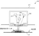
図1に本発明を適用した画像形成装置の概略を示す。画像形成装置100は、フルカラーレーザプリンタであるが、他のタイプのプリンタ、ファクシミリ、複写機、印刷機、複写機とプリンタとの複合機等、他の画像形成装置であっても良い。画像形成装置100は、外部から受信した画像情報に対応する画像信号に基づき画像形成処理を行なう。画像形成装置100は、一般にコピー等に用いられる普通紙の他、OHPシートや、カード、ハガキ等の厚紙や、封筒等の何れをもシート状の記録媒体として画像形成を行なうことが可能である。
FIG. 1 shows an outline of an image forming apparatus to which the present invention is applied. The
画像形成装置100は、イエロー、マゼンタ、シアン、ブラックの各色に色分解された色にそれぞれ対応する像としての画像を像形成物質としてのトナーを担持することで形成可能な第1の像担持体としての潜像担持体である感光体たる感光体ドラム20Y、20M、20C、20BKを平行配設したタンデム構造、言い換えるとタンデム方式を採用している。
The
感光体ドラム20Y、20M、20C、20BKは、画像形成装置100の本体99の図示しないフレームに回転自在に支持された可撓性を有する第2の像担持体としての中間転写体たる無端ベルト状のベルトである中間転写ベルトとしての転写ベルト11の移動方向であって図1において反時計回り方向であるA1方向の上流側からこの順で等間隔で並列に並んでいる。各符号の数字の後に付されたY、M、C、BKは、イエロー、マゼンタ、シアン、黒用の部材であることを示している。
The
各感光体ドラム20Y、20M、20C、20BKはそれぞれ、イエロー(Y)、マゼンタ(M)、シアン(C)、ブラック(BK)の画像を形成するための作像ユニットである画像形成ユニット60Y、60M、60C、60BKに備えられている。
Each of the
感光体ドラム20Y、20M、20C、20BKは、本体99の内部のほぼ中央部に配設された無端のベルトとして構成された転写ベルト11の外周面側すなわち作像面側に位置している。
The
転写ベルト11は、各感光体ドラム20Y、20M、20C、20BKに対峙しながら矢印A1方向に移動可能となっている。各感光体ドラム20Y、20M、20C、20BKに形成された可視像すなわちトナー像は、矢印A1方向に移動する転写ベルト11に対しそれぞれ重畳転写され、その後、記録媒体である記録材としての用紙たる転写紙Sに一括転写されるようになっている。よって画像形成装置100は中間転写方式言い換えると間接転写方式の画像形成装置となっている。したがって画像形成装置100はタンデム型間接転写方式の画像形成装置である。
The
転写ベルト11は、その下側の部分が各感光体ドラム20Y、20M、20C、20BKに対向しており、この対向した部分が、各感光体ドラム20Y、20M、20C、20BK上のトナー像を転写ベルト11に転写する1次転写部58を形成している。
The lower portion of the
転写ベルト11に対する重畳転写は、転写ベルト11がA1方向に移動する過程において、各感光体ドラム20Y、20M、20C、20BKに形成されたトナー像が、転写ベルト11の同じ位置に重ねて転写されるよう、転写ベルト11を挟んで各感光体ドラム20Y、20M、20C、20BKに対向する位置に配設された一次転写手段としての1次転写ローラ12Y、12M、12C、12BKによる電圧印加によって、A1方向上流側から下流側に向けてタイミングをずらして行われる。
In the superimposing transfer to the
転写ベルト11は、ベース層を伸びの少ない材質で構成し、ベース層の表面を平滑性の良い材質によって覆ったコート層とし、ベース層にコート層を重ねて形成した多層構造となっている。ベース層の材質としては、たとえばフッ素樹脂、PVDFシート、ポリイミド系樹脂が挙げられ、本形態ではポリイミドを使用している。コート層の材質としては、たとえばフッ素系樹脂等が挙げられる。
The
転写ベルト11は、その縁部にそれぞれ、寄り止め部材としての図示しない寄り止めガイドを有している。寄り止めガイドは、転写ベルト11がA1方向に回転するときに、主走査方向に対応した、図1における紙面と垂直な幅方向のうちの何れかの方向に偏倚することを防止するために配設されている。寄り止めガイドは、ウレタンゴム製であるが、その他、シリコンゴムなど各種ゴム材料により構成することができる。
Each of the
転写ベルト11は、幅方向において、A4横サイズの転写紙Sに対応した幅を有している。よって、画像形成装置100は、最大でA3縦サイズの転写紙Sに対する画像形成が可能となっている。
The
画像形成装置100は、本体99内に、4つの画像形成ユニット60Y、60M、60C、60BKと、各感光体ドラム20Y、20M、20C、20BKの上方に対向して配設され、転写ベルト11を備えた中間転写ユニットとしての転写ベルトユニット10と、図1における転写ベルト11の右側において転写ベルト11に対向して配設された2次転写手段としての2次転写装置5と、画像形成ユニット60Y、60M、60C、60BKの下方に対向して配設された潜像形成手段としての光書込みユニットである書き込みユニットとしての露光装置たる光走査装置8とを有している。
The
画像形成装置100はまた、本体99内に、転写ベルト11と2次転写装置5との間の2次転写部57に向けて搬送される転写紙Sを多数枚積載可能な給紙カセットとしてのシート給送装置61と、シート給送装置61から搬送されてきた記録紙Sを、画像形成ユニット60Y、60M、60C、60BKによるトナー像の形成タイミングに合わせた所定のタイミングで、2次転写部57に向けて繰り出すレジストローラ対4と、転写紙Sの先端がレジストローラ対4に到達したことを検知する図示しないセンサとを有している。
The
画像形成装置100はまた、本体99内に、トナー像を転写された転写紙Sに同トナー像すなわち未定着トナー画像を定着させるためのベルト定着方式の定着ユニットとしての定着装置6と、シート給送装置61から送り出された転写紙Sを搬送する図示しない搬送ローラを備え、中途部にレジストローラ対4、定着装置6を配設された給紙路32と、給紙路32の終端に位置し定着済みの転写紙Sである画像出力物を本体99の外部に排出する排出ローラである排紙ローラ対としての排紙ローラ7と、転写ベルトユニット10の上方に配設され、イエロー、シアン、マゼンタ、ブラックの各色のトナーを充填されたトナーボトル9Y、9M、9C、9BKと、本体99の上側に配設され排出ローラ7により本体99の外部に排出された転写紙Sを積載する排紙部としての排紙トレイ17とを有している。
The
画像形成装置100はまた、本体99内に、各感光体ドラム20Y、20M、20C、20BKを回転駆動する図示しない駆動手段としての駆動モータを含む駆動装置と、画像形成によって生じた、不要となったトナーを貯留する図示しない廃トナーボトルと、画像形成装置100の動作全般を制御する図示しないCPU、メモリ等を含む制御手段91とを有している。
画像形成ユニット60Y、60M、60C、60BKと、転写ベルトユニット10と、光走査装置8と、定着装置6とは、シート給送装置61の上方に位置する画像形成部を構成している。
The
The image forming units 60 </ b> Y, 60 </ b> M, 60 </ b> C, 60 </ b> BK, the
転写ベルトユニット10は、転写ベルト11の他に、1次転写バイアスローラとしての1次転写ローラ12Y、12M、12C、12BKと、転写ベルト11を巻き掛けられた、駆動部材である駆動ローラ72と、張架ローラとしてのクリーニング対向ローラ74と、駆動ローラ72及びクリーニング対向ローラ74とともに転写ベルト11を張架する支持ローラとしての張架ローラ75、33と、転写ベルト11に対向して配設され転写ベルト11表面をクリーニングする中間転写体クリーニング装置であるベルトクリーニング装置としてのクリーニング装置13とを有している。
In addition to the
転写ベルトユニット10はまた、張架ローラ75に対向する位置で転写ベルト11の外周面に対向して配置され、後述するプロセスコントロールモードにおいて転写ベルト11に形成されるプロセスコントロール用のトナー像である濃度検知用パッチを光学的に検知する検知手段としての光学的検知手段である光学センサ30と、駆動ローラ72を回転駆動する図示しない駆動モータを備えた図示しない駆動系と、1次転写ローラ12Y、12M、12C、12BKにそれぞれ独立して1次転写バイアスを印加する図示しない第1の転写バイアス印加手段としての電源及び制御手段91の一機能として実現された第1の転写バイアス制御手段とを有している。
The
駆動ローラ72、クリーニング対向ローラ74、張架ローラ75、33は、転写ベルト11を回転搬送可能に掛け渡し、掛け回した支持ローラとなっている。クリーニング対向ローラ74、張架ローラ75、33は、駆動ローラ72によって回転駆動される転写ベルト11に連れ回りする従動ローラとなっている。支持ローラ72、74、75、33のうち、張架ローラ33のみが転写ベルト11の外周面である表面に当接し、他の支持ローラ72、74、75は、転写ベルト11の内周面である裏面に当接している。1次転写ローラ12Y、12M、12C、12BKは、転写ベルト11をその裏面から感光体ドラム20Y、20M、20C、20BKに向けて押圧してそれぞれ1次転写ニップを形成する。この1次転写ニップは、転写ベルト11の、クリーニング対向ローラ74と張架ローラ75との間に張り渡した部分において形成されている。クリーニング対向ローラ74と張架ローラ75とは、1次転写ニップを安定化する機能を有する。
The driving
各1次転写ニップには、1次転写バイアスの影響により、感光体ドラム20Y、20M、20C、20BKと1次転写ローラ12Y、12M、12C、12BKとの間に1次転写電界が形成される。感光体ドラム20Y、20M、20C、20BK上に形成された各色のトナー像は、この1次転写電界やニップ圧の影響によって転写ベルト11上に1次転写される。
In each primary transfer nip, a primary transfer electric field is formed between the
駆動ローラ72は、転写ベルト11を介して2次転写装置5を当接されており、2次転写部57を形成している。よって駆動ローラ72は2次転写対向ローラを兼ねている。
クリーニング対向ローラ74は、転写ベルト11に、転写に適した所定の張力を与える加圧部材としてのテンションローラたる機能を有している。
The driving
The cleaning
クリーニング装置13は、図1においてクリーニング対向ローラ74の左方に配設されている。クリーニング装置13は、クリーニング対向ローラ74に対向する位置、すなわち、A1方向において2次転写部57の下流側且つ1次転写部58の上流側の位置で転写ベルト11に当接するように配設されたクリーニングブレード13aと、クリーニングブレード13aをその内部に収容したケース13bとを有している。
The
クリーニング装置13は、転写ベルト11上の残留トナー等の異物をクリーニングブレード13aで掻き取り、除去して、転写ベルト11をクリーニングするようになっている。
転写ベルトユニット10は、本体99に対して一体で着脱可能となっている。
The
The
光学センサ30は、張架ローラ75の近傍における転写ベルト11の外部に配置されている。この点、張架ローラ75は、転写ベルト11を挟んで光学センサ30が対向した対向ローラとなっている。
The
図2に示すように、光学センサ30は、実装基板31と、実装基板31に実装され照射対象物である転写ベルト11に向けて発光する発光手段としてのLED36と、LED36によって転写ベルト11に向けて照射され転写ベルト11で反射された光の正反射光を受光する受光手段である正反射光受光手段としての正反射光受光素子37と、かかる光の拡散光を受光する受光手段である拡散反射光受光手段としての拡散反射光受光素子38と、LED36、正反射光受光素子37、拡散反射光受光素子38を収容し外乱光の入射を防止するケース39とを有している。
As shown in FIG. 2, the
LED36は正反射光受光素子37と拡散反射光受光素子38との間に配置されている。LED36、正反射光受光素子37、拡散反射光受光素子38は基板31の面方向に対して平行な方向に向いて実装されている。ケース39は、黒色の樹脂で成型されている。発光手段としてはレーザーダイオード、受光手段としてはフォトトランジスタ、フォトダイオードなど適宜が用いられる。
The
光学センサ30は、受光素子である正反射光受光素子37を用いた校正動作を行われるようになっている。この校正動作は、LED36に流す電流値を大きくすると発光量が増して正反射光受光素子37によって検知される正反射光出力が大きくなり、逆にLED36に流す電流値を小さくすると発光量が減って正反射光受光素子37によって検知される正反射光出力が小さくなることを利用して行われるものであり、正反射光受光素子37の出力値が所定の範囲内となるように、LED36に流す電流を変化させLED36の光量を調整する調整動作である。以下、かかる校正動作、調整動作をVsg調整という。なお、図2は、プロセスコントロール時において濃度検知用パッチを検出している状態を示している。
The
まず、Vsg調整を開始するときには、LED36をONして、転写ベルト11の地肌部すなわちトナー像が形成されていない部分の正反射出力値を正反射光受光素子37により検出する。そして、この正反射光出力値が4±0.5[V]となるようにLED36の電流値Ifsgを調整する。このとき、二分探索法を用いて正反射出力値が4.0[V]に最も近くなる電流値Ifsgを検出する。Vsg調整において、電流値Ifsgの上限値は30[mA]と定められている。これは、LED36が破損しないように設定された値である。
First, when starting the Vsg adjustment, the
二分探索法の結果、正反射出力値が4±0.5[V]の範囲内に入った場合にはそのときの電流値Ifsgを制御手段91のメモリに保存する。正反射出力値が4±0.5[V]の範囲に入らない場合には、Vsg調整失敗となる。この失敗が連続して3回続いた場合に異常が発生したと判断して画像形成装置100を停止する。
As a result of the binary search method, when the regular reflection output value falls within the range of 4 ± 0.5 [V], the current value Ifsg at that time is stored in the memory of the control means 91. When the regular reflection output value does not fall within the range of 4 ± 0.5 [V], Vsg adjustment fails. When this failure continues three times in succession, it is determined that an abnormality has occurred and the
ただし、Vsg調整には時間がかかるため、電流値Ifsgを調整する前に、前回のVsg調整時の電流値Ifsgを用いて転写ベルト11の地肌部に所定の時間LED36の光を照射し、その正反射光を正反射光受光素子37で検出し、検出した正反射光出力の平均値を求め、平均値が所定の範囲内である場合には、電流値Ifsgの調整を行う必要性がないと判断し、Vsg調整は実行しない。
However, since it takes time to adjust the Vsg, before adjusting the current value Ifsg, the background portion of the
シート給送装置61は、転写紙Sを複数枚重ねた転写紙束の状態で収容するものであり、本体99の下部に配設されている。
シート給送装置61は、最上位の転写紙Sの上面に押圧される給紙ローラとしての給送ローラ3を有しており、給送ローラ3が所定のタイミングで反時計回り方向に回転駆動されることにより、最上位の転写紙Sを1枚ずつ分離してレジストローラ対4に向けて給送するようになっている。この点、給紙ローラ3は分離ローラとしても機能する。
シート給送装置61から送り出された転写紙Sは、給紙路32を経てレジストローラ対4に至り、レジストローラ対4のローラ間に挟まれる。
The sheet feeding device 61 accommodates a plurality of transfer sheets S in a state of a stack of transfer sheets, and is disposed in the lower part of the
The sheet feeding device 61 has a
The transfer sheet S delivered from the sheet feeding device 61 reaches the registration roller pair 4 through the sheet feeding path 32 and is sandwiched between the rollers of the registration roller pair 4.
2次転写装置5は、駆動ローラ72に対向して配置されている。2次転写装置5は、駆動ローラ72との間で転写ベルト11を挟むようにして配設され、転写ベルト11との間を通過する転写紙Sに転写ベルト11上のトナー像を転写可能とするための2次転写部材である転写部材としての2次転写ローラ64と、2次転写ローラ64をクリーニングする図示しないクリーニング装置と、2次転写ローラ64を駆動ローラ72に向けて付勢した付勢部材としての図示しないバネとを有している。
The
2次転写ローラ64と、転写ベルト11の2次転写部57近傍の一部とは、給紙路32に臨むように配設されている。2次転写ローラ64は、駆動ローラ72との間で2次転写バイアスを印加する図示しない第2の転写バイアス印加手段としての電源及び制御手段91の一機能として実現された第2の転写バイアス制御手段を接続されている。
The
電源は、2次転写ローラ64に、転写ベルト11上に担持されたトナー像を構成するトナーの帯電極性と逆極性のバイアスを印加する。よって2次転写ローラ64は、電源によるバイアス印加により転写ベルト11上に担持されたトナー像に対する引力を発生させ、これによってかかるトナー像を転写紙S上に静電転写する。この点、2次転写ローラ64は引力ローラとして機能する。
The power source applies to the secondary transfer roller 64 a bias having a polarity opposite to the charging polarity of the toner constituting the toner image carried on the
定着装置6は、図示しないヒータを内部に有する中空の金属ローラである加熱ローラ62と、加熱ローラ62に巻き掛けられた定着ベルト63と、加熱ローラ62とともに定着ベルト63を巻き掛けたゴム製の定着ローラ68と、定着ローラ68との間で定着ベルト63に圧接し圧接部であるニップ部としての定着ニップ70を形成する中空のローラである加圧ローラ69と、加圧ローラ69の内部に配設された図示しないヒータとを有している。
The fixing
定着装置6はまた、加熱ローラ62及び定着ローラ68とともに定着ベルト63を巻き掛けたテンションローラ73と、テンションローラ73に、定着ベルト63の張力を増加する向きの付勢力を与えるようにテンションローラ73を定着ベルト63の内側から外側に向かって付勢した付勢部材としての図示しないスプリングと、定着ベルト63の温度を検知する温度検知手段としての図示しないサーミスタと、定着装置6に備えられた以上の構成を囲繞し内包して作業者にかかる構成が直接触れられないようにしたケーシングとしての定着ケース85とを有している。
The fixing
定着装置6は、トナー像を担持した転写紙Sを定着ニップ70に挟み込む態様で通すことで、熱と圧力との作用により、転写紙Sに担持されたトナー像を同転写紙Sの表面に定着するようになっている。
The fixing
トナーボトル9Y、9M、9C、9BK内のイエロー、シアン、マゼンタ、ブラックの各色のトナーは、ワックス成分が内部に均一に分散した重合トナーであって、転写ベルト11に付着した際、ワックス成分の外部への析出が少なくなっている。かかる各色のトナーは、図示しない搬送経路を経て、所定の補給量だけ、画像形成ユニット60Y、60M、60C、60BKに備えられた現像装置80Y、80M、80C、80BKに補給される。
The yellow, cyan, magenta, and black toners in the
画像形成ユニット60Y、60M、60C、60BKは互いに同様の構成となっている。画像形成ユニット60Y、60M、60C、60BKはそれぞれ、感光体ドラム20Y、20M、20C、20BKの周囲に、図1中時計方向であるその回転方向B1に沿って、作像手段として、1次転写ローラ12Y、12M、12C、12BKと、クリーニング手段としてのクリーニング器であるクリーニング装置71Y、71M、71C、71BKと、除電手段としての図示しない除電装置と、帯電バイアス形成のためにAC帯電を行なう帯電ローラ51Y、51M、51C、51BKを備えた帯電手段としての帯電装置79Y、79M、79C、79BKと、2成分現像剤により現像を行う現像手段としての現像装置80Y、80M、80C、80BKとを有している。
The
図1または図2に示すように、現像装置80Y、80M、80C、80BKは、感光体ドラム20Y、20M、20C、20BKに対向するように配置された現像剤担持体としての現像ローラ76Y、76M、76C、76BKと、現像剤を搬送しながら撹拌する2軸のスクリューである第1スクリュー65Y、65M、65C、65BK、第2スクリュー66Y、66M、66C、66BKとを有している。
As shown in FIG. 1 or FIG. 2, the developing
現像装置80Y、80M、80C、80BKはまた、第1スクリュー65Y、65M、65C、65BK、第2スクリュー66Y、66M、66C、66BKをそれぞれ収納した図示しない現像剤室と、第2スクリュー66Y、66M、66C、66BKを収納した現像剤室の下部に位置し現像剤中のトナー濃度を検知するトナー濃度検知センサとしてのトナー濃度センサ67Y、67M、67C、67BKとを有している。
The developing
現像装置80Y、80M、80C、80BKはまた、トナー濃度センサ67Y、67M、67C、67BKの出力に応じてトナーボトル9Y、9M、9C、9BK内のトナーを装置本体内に補給するトナー補給手段としての図示しないトナー補給装置と、トナー補給装置によってトナーの補給を受けるトナー補給口77Y、77M、77C、77BKと、現像ローラ76Y、76M、76C、76BKと感光体ドラム20Y、20M、20C、20BKとの間の現像領域に現像バイアスを印加する図示しないバイアス印加手段とを有している。
The developing
第1スクリュー65Y、65M、65C、65BK、第2スクリュー66Y、66M、66C、66BKは、現像剤を現像剤室内において循環搬送する。第1スクリュー65Y、65M、65C、65BKは、現像剤を現像ローラ76Y、76M、76C、76BKに汲み上げ、現像ローラ76Y、76M、76C、76BKに担持させる。現像ローラ76Y、76M、76C、76BKに担持された現像剤は、現像ローラ76Y、76M、76C、76BKの回転に伴い現像領域を通過するときに感光体ドラム20Y、20M、20C、20BKの表面に後述のようにして形成された静電潜像をトナーで現像する。現像領域を通過した現像剤は現像剤室に戻される。
The first screws 65Y, 65M, 65C, 65BK and the
トナー濃度センサ67Y、67M、67C、67BKは、トナー透磁率を測定するものとなっており、測定結果を制御手段91に出力する。制御手段91は、トナー濃度センサ67Y、67M、67C、67BKの出力値Vtをトナー濃度の制御基準値Vtrefと比較し、その差分に応じて補給すべきトナーの量すなわちトナー補給量を、そのメモリに記憶している演算式から算出し、トナー補給装置を駆動して、トナー補給口77Y、77M、77C、77BKを通じて算出した量のトナーを現像剤室内に補給する。
The
画像形成ユニット60Y、60M、60C、60BKはそれぞれ、本体99に固定された図示しないガイドレールに沿って本体99に対して引き出し自在であるとともに、本体99に押し込むことが可能であり、本体99に対して着脱自在に設置されたプロセスカートリッジとなっている。プロセスカートリッジとしての画像形成ユニット60Y、60M、60C、60BKはそれぞれ、本体99に押し込むと、画像形成に適した所定の位置に装填され、位置決めされるようになっている。このようにプロセスカートリッジ化することは、交換部品として取り扱うことが可能であるため、メンテナンス性が著しく向上し、大変好ましい。またプロセスカートリッジの要素である各部の寿命が同等とされているため、不要な交換が防止、抑制され、さらに好ましい構成となっている。
The
このような構成の画像形成装置100において、カラー画像を形成すべき旨の信号がユーザによって入力されると、制御手段91において形成すべき所望の画像であるフルカラー画像に対応した画像情報を含む印刷ジョブである画像形成ジョブがメモリに記憶され保持されるとともに、駆動ローラ72が駆動され、転写ベルト11、クリーニング対向ローラ74、張架ローラ75、33が従動回転するとともに、感光体ドラム20Y、20M、20C、20BKがB1方向に回転駆動される。
In the
感光体ドラム20Y、20M、20C、20BKはそれぞれ、B1方向への回転に伴い、帯電装置79Y、79M、79C、79BKにより帯電バイアスによって表面を所定の極性に一様に帯電され、光走査装置8からの、同図の紙面垂直方向に略一致する主走査方向への、上方へ向けた、光変調されたレーザー光の露光走査すなわち照射により、イエロー、マゼンタ、シアン、ブラックの各色に対応した静電潜像による、画像情報に応じた潜像を形成され、この静電潜像を現像装置80Y、80M、80C、80BKの現像バイアス及びトナーの帯電によりイエロー、マゼンタ、シアン、ブラックの各色のトナーにより現像されて顕像化され、マゼンタ、シアン、ブラックの各色のトナー像によって構成された単色画像が形成される。
As the
なお、制御手段91は、光走査装置8を駆動して各色に対応した静電潜像を形成するにあたり、メモリに記憶した画像情報をイエロー、マゼンタ、シアン、ブラックの各色の色情報に分解し、各色に分解された単色の画像情報である各色画像情報に基づいて光走査装置8を駆動する。
Note that the
現像により得られたイエロー、マゼンタ、シアン、ブラックの各色のトナー像は、A1方向の最上流側に位置するイエロートナー画像から、マゼンタトナー画像、シアントナー画像、ブラックトナー画像の順で、順次、1次転写ローラ12Y、12M、12C、12BKによって形成される1次転写バイアスにより、A1方向に回転している転写ベルト11上の同じ位置に1次転写されて色重ねが行われ、転写ベルト11上にはフルカラーのトナー画像である合成カラー画像が形成され担持される。
The yellow, magenta, cyan, and black toner images obtained by development are sequentially from the yellow toner image located on the most upstream side in the A1 direction, in the order of a magenta toner image, a cyan toner image, and a black toner image. The primary transfer bias formed by the
一方、カラー画像を形成すべき旨の信号の入力に伴い、シート給送装置61に備えられた給送ローラ3が回転して転写紙Sを繰り出すとともに1枚ずつ分離して給紙路32に送り込み、給紙路32に送り込まれた転写紙Sは図示しない搬送ローラでさらに搬送されレジストローラ対4に突き当てられた状態で停止する。
On the other hand, when a signal indicating that a color image should be formed is input, the feeding
転写ベルト11上に重ね合わされた合成カラー画像が転写ベルト11のA1方向の回転に伴って2次転写部57まで移動するタイミングに合わせて、言い換えると給紙タイミングを計られて、レジストローラ対4が回転し、2次転写部57では、合成カラー画像が、2次転写部57に送り込まれた転写紙Sに密着し、2次転写バイアス及びニップ圧の作用によって転写紙Sに一括して2次転写され、記録される。
In accordance with the timing at which the composite color image superimposed on the
転写紙Sは2次転写装置5によって搬送されて定着装置6に送り込まれ、定着装置6において定着ベルト63と加圧ローラ69との間の定着ニップ70すなわち定着部を通過する際、熱と圧力との作用により、担持したトナー像すなわち合成カラー画像を定着される。
The transfer sheet S is transported by the
定着装置6を通過した、合成カラー画像を定着済みの転写紙Sは、排紙ローラ7を経て本体99外に排出され、本体99の上部の排紙トレイ17上にスタックされる。
The transfer sheet S on which the composite color image has been fixed, which has passed through the fixing
感光体ドラム20Y、20M、20C、20BKは、転写後に残留し不要なトナーとなった残留トナーである転写残トナーをクリーニング装置71Y、71M、71C、71BKにより表面から拭い去られて除去され、除電装置によって除電され、表面電位を初期化されて、帯電装置79Y、79M、79C、79BKによる次の帯電に供される。クリーニング装置71Y、71M、71C、71BKにより感光体ドラム20Y、20M、20C、20BKの表面から除去された転写残トナーは廃トナーボトルに貯留される。
The
2次転写を終えた2次転写部57通過後の転写ベルト11は、クリーニング装置13に備えられたクリーニングブレード13aによって転写後にその表面に残留した不要なトナーである転写残トナーを拭い去られ、除去されてクリーニングされ、次の転写に備える。クリーニング装置13により転写ベルト11の表面から除去された転写残トナーは廃トナーボトルに貯留される。
The
画像形成装置100は、このようにユーザ指定の画像形成を行う画像形成モードとは別に、電源投入時、またはある所定枚数通紙後すなわち画像形成後に各色の画像濃度を適正化するためにプロセスコントロール動作が実行されるプロセスコントロールモードを備えている。このプロセスコントロール動作では、各色複数の階調パターンとしての濃度検知用パッチを、帯電バイアス、現像バイアスとを適当なタイミングで順次切り替えることにより転写ベルト11上に作像し、これら階調パターンを光学センサ30により検知し、その出力電圧を付着量に変換して、現像能力を表す現像γ、現像開始電圧Vkの算出を行い、この算出値に基づき、現像バイアス値及びトナー濃度制御目標値の変更をする制御を行っている。
In addition to the image forming mode in which the user-specified image formation is performed in this manner, the
図4を参照しながらプロセスコントロール動作の内容について説明する。
(1)装置立ち上げ(ステップS1)
画像形成装置100の電源投入時、所定枚数印刷時に各種モータや各種デバイスのバイアスがオンされ、プロセスコントロールを実行するための準備が行われる。
The contents of the process control operation will be described with reference to FIG.
(1) Device startup (step S1)
When the
(2)Vsg調整(ステップS2)
すでに説明したようにしてVsg調整を行う。すなわちLED36をONして、転写ベルト11の地肌部の正反射出力値を正反射光受光素子37により検出し、この正反射光出力値が4±0.5[V]となるようにLED36の電流値を調整する。二分探索法を用いて正反射出力値が4.0[V]に最も近くなるIfsgを検出する。
(2) Vsg adjustment (step S2)
Vsg adjustment is performed as described above. That is, the
(3)現像装置80Y、80M、80C、80BKのそれぞれにおいてトナー濃度センサ67Y、67M、67C、67BKの出力(Vt)を取得する(ステップS3)。これはこの検知時におけるトナー濃度を知るために測定するものであって、後述するトナー濃度制御基準値(Vtref)の補正に必要なものである。
(3) The outputs (Vt) of the
(4)階調パターンの作成(ステップS4)
これは現像γを検出するために必要であり、具体的には、光学センサ30が設けられた位置に対応するよう、図5に示すように、主走査方向の幅10[mm]、副走査方向の幅14.4[mm]、パターン間隔5.6[mm]で濃度検知用パッチを形成することで階調パターンを形成する。なお、主走査方向は転写ベルト11の幅方向に一致し、副走査方向は主走査方向に直交する、A1方向に平行な方向である。なお、同図に示されているように、光学センサ30は、転写ベルト11に対し、主走査方向における中央部であるCenterと、主走査方向である各端部であるFront、Rearとでそれぞれ対向するように、計3つが配置されている。また、符号49は、各光学センサ30を一体に支持した検出手段支持部材としての支持部材である支持板を示している。
(4) Creation of gradation pattern (step S4)
This is necessary for detecting the development γ. Specifically, as shown in FIG. 5, the width 10 [mm] in the main scanning direction and the sub-scanning correspond to the position where the
作成する各色の濃度検知用パッチの数はドラム間ピッチに収まる数とするのが望ましい。ドラム間ピッチとは、各感光体ドラム20Y、20M、20C、20BK相互間の距離であり、各感光体ドラム20Y、20M、20C、20BKにおいて同時に光走査装置8による書き込み等の画像形成を開始した場合に各感光体ドラム20Y、20M、20C、20BKにおいて形成された画像の先端の、転写ベルト11上における相互の間隔に一致する。
It is desirable that the number of density detection patches for each color to be created be a number that fits in the pitch between the drums. The inter-drum pitch is a distance between the
作成する各色の濃度検知用パッチの数をドラム間ピッチに収まる数とするのは、作成する各色の階調パターンの全長がドラム間ピッチより長くなると、他の色と重なってしまうことになることから、書き込みの遅延を行い、他の色の階調パターンの作成を待ってから次の色の階調パターンの書き込みを開始しなくてはならなくなり、このような動作となった場合、全色の階調パターンを作成が完了するまでの時間が長くなってしまうことになり、調整動作にかかる時間が長くなるためである。 The number of density detection patches for each color to be created is the number that fits in the pitch between drums. If the total length of the gradation pattern for each color to be created is longer than the pitch between drums, it will overlap with other colors. After that, the writing delay must be performed, and the writing of the next color gradation pattern must be started after waiting for the creation of the gradation pattern for the other colors. This is because it takes a long time to complete the generation of the gradation pattern, and the time required for the adjustment operation becomes long.
本形態においては、ドラム間ピッチが100[mm]のため、ドラム間ピッチに収めることができる各色最大の階調パターン数は、
(ドラム間ピッチ100[mm])/(パターンの副走査方向の幅:14.4[mm]+パターン間隔:5.6[mm])=5
より、各色5パッチ以下でトナーパッチを作成する。
In this embodiment, since the pitch between the drums is 100 [mm], the maximum number of gradation patterns that can be accommodated in the pitch between the drums is
(Drum pitch 100 [mm]) / (Width in pattern sub-scanning direction: 14.4 [mm] + pattern interval: 5.6 [mm]) = 5
Thus, a toner patch is created with 5 or less patches for each color.
そのパターン形成の書き込みに際し、露光量はフル露光すなわち各感光体ドラム20Y、20M、20C、20BKが充分に除電される値とし、現像バイアスと帯電バイアスをパターンごとに変更することで階調パターンを作成する。
In writing the pattern formation, the exposure amount is set to a value at which full exposure is performed, that is, the
(5)階調パターンを光学センサ30で検出する(ステップS5)
各感光体ドラム20Y、20M、20C、20BKにおいて形成され転写ベルト11に転写された各濃度検知用パッチを光学センサ30で検知し、トナー付着量を求める。C、M、Yの階調パターンについては正反射光受光素子37と拡散反射光受光素子38とにより正反射光と拡散反射光との両方を検知し、Bkの階調パターンについては正反射光受光素子37により正反射光のみ検知する。
(5) The gradation pattern is detected by the optical sensor 30 (step S5).
Each density detection patch formed on each of the
ただし、濃度検出用パッチである濃度検出用パターンはCenterに配置された1つの光学センサ30で検出し、この光学センサ30で全色の階調パターンの検知を行う。Front、Rear位置に設置してある光学センサ30は色ずれ補正制御等を目的とした位置ズレ補正制御を行うために使用する。
However, the density detection pattern, which is a density detection patch, is detected by one
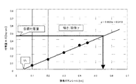
(6)現像γと現像開始電圧Vkを求める(ステップS6)
濃度検出用パッチであるトナーパッチを作像したときの現像ポテンシャルとステップS5で求められたトナー付着量との関係から現像γ、現像開始電圧Vkを求める。具体的には、図6に示すように、横軸を現像ポテンシャル、縦軸をトナー付着量とし、最小二乗法により1次直線式を求める。その1次直線式の傾きを現像γとし、X切片を現像開始電圧Vkとする。
(6) Obtain development γ and development start voltage Vk (step S6).
The development γ and the development start voltage Vk are obtained from the relationship between the development potential when the toner patch, which is a density detection patch, is formed and the toner adhesion amount obtained in step S5. Specifically, as shown in FIG. 6, the horizontal axis represents the development potential, the vertical axis represents the toner adhesion amount, and a linear equation is obtained by the least square method. The slope of the linear equation is defined as development γ, and the X-intercept is defined as development start voltage Vk.
(7)目標トナー付着量を得るのに必要な現像バイアスを求める(ステップS7)
ステップS6で求めた1次直線式に基づき、縦軸上の目標付着量に対応する横軸上の現像ポテンシャルを求める。目標付着量はあらかじめトップ濃度を得るのに必要な値が決められているものであり、トナー顔料の着色度合いとトナー粒径で決まるが、一般的には0.4〜0.6[mg/cm^2]程度である。
(7) A developing bias necessary for obtaining the target toner adhesion amount is obtained (step S7).
Based on the linear equation obtained in step S6, the development potential on the horizontal axis corresponding to the target adhesion amount on the vertical axis is obtained. The target adhesion amount is determined in advance as a value necessary for obtaining the top concentration, and is determined by the coloring degree of the toner pigment and the toner particle diameter. cm ^ 2].
ここで求めた現像バイアス値を現像装置80Y、80M、80C、80BKの現像バイアス:Vbとする。帯電バイアス:Vc は、現像装置80Y、80M、80C、80BK内の現像剤中のキャリアが感光体ドラム20Y、20M、20C、20BKに飛翔しない程度の値であらかじめ決定されている。Vb=400〜750[−V]、Vc=Vb+100〜200[−V]程度が一般的である。このようにして求めたVb及びVcを作像時の現像バイアス、帯電バイアスとして設定する。
The developing bias value obtained here is set as developing bias Vb of the developing
(8)トナー濃度制御基準値Vtrefを補正する(ステップS8)
現像γとトナー濃度センサ出力Vtからトナー濃度制御基準値Vtrefを補正する。 すなわち、Δγ=現像γ検出値−現像γ目標値、を求める。ここで、現像γ目標値はあらかじめ装置毎に決められ、たとえば1.0[mg/cm^2/kV]とする。この値は、現像ポテンシャルが1000[V](1[kV])で1.0[mg/cm^2]のトナーが感光体ドラム20Y、20M、20C、20BKに付着することを示し、現像開始電圧=0V、目標トナー付着量が0.5[mg/cm^2]であれば、500[V]の現像ポテンシャルが必要となる。
(8) The toner density control reference value Vtref is corrected (step S8).
The toner density control reference value Vtref is corrected from the development γ and the toner density sensor output Vt. That is, Δγ = development γ detection value−development γ target value is obtained. Here, the development γ target value is determined in advance for each apparatus, and is, for example, 1.0 [mg /
現像ポテンシャル=|Vb−Vl|であるので、Vl=50[−V]とすると、Vb=550[−V]となる。V1は露光後電位をあらわし、充分露光した場合の感光体電位なので感光体特性に依存する。Δγが所定の値を超えるとVbが設定可能な範囲を超えたり、異常画像が発生したりするので、Δγが目標範囲になるようにトナー濃度制御基準値Vtrefを補正する。ただし、このときのVtがVtrefと大きく異なっているときは補正を行わない。 Since development potential = | Vb−Vl |, when Vl = 50 [−V], Vb = 550 [−V]. V1 represents a post-exposure potential, and depends on the photoconductor characteristics since it is a photoconductor potential when fully exposed. If Δγ exceeds a predetermined value, Vb exceeds a settable range or an abnormal image occurs. Therefore, the toner density control reference value Vtref is corrected so that Δγ becomes the target range. However, no correction is made when Vt at this time is significantly different from Vtref.
補正の例を示す。
・補正条件1:
Δγ≧0.30[mg/cm^2/kV](高い)でかつVt−Vtref≧−0.2[V]のとき、Vtref=Vt−0.2[V]とする。つまり、現時点よりトナー濃度を下げるように制御基準値を設定する。
・補正条件2:
Δγ≦0.30[mg/cm^2/kV](低い)でかつVt−Vtref≦0.2[V]のとき、Vtref=Vt+0.2[V]とする。つまり、現時点よりトナー濃度を上げるように制御基準値を設定する。
補正条件1及び補正条件2以外ではVtref=前回値とする。
An example of correction will be shown.
-Correction condition 1:
When Δγ ≧ 0.30 [mg / cm ^ 2 / kV] (high) and Vt−Vtref ≧ −0.2 [V], Vtref = Vt−0.2 [V]. That is, the control reference value is set so as to lower the toner density from the current time.
-Correction condition 2:
When Δγ ≦ 0.30 [mg / cm ^ 2 / kV] (low) and Vt−Vtref ≦ 0.2 [V], Vtref = Vt + 0.2 [V]. That is, the control reference value is set so as to increase the toner density from the current time.
Other than the
転写ベルト11のカール癖について説明する。
転写ベルトユニット10と同様の構成の中間転写ユニットを高湿環境下に長時間放置し、この中間転写ユニットを用いて転写ベルト11と同様のベルトの駆動を行い、光学センサ30と同様の光学センサでベルト地肌部のセンサ出力を測定したものを図7に示す。同図から、一部でセンサ出力が大きく変動していることが分かる。このセンサ出力が大きく変動している部分がカール癖の生じている箇所を光学センサで検知した時の結果である。このようにベルトにカール癖が生じると、その影響により光学センサと検知対象との検知距離がずれる結果として、センサ出力が変動する。よって、カール癖が生じると、濃度検出用パッチ、あるいは階調パターンの検知精度が低下し、プロセスコントロールを行っても安定した画像濃度制御が行われなくなる。
The curl wrinkles of the
An intermediate transfer unit having the same configuration as that of the
そこで、転写ベルトユニット10においては、カール癖による、かかるセンサ出力変動を低減するために以下の構成を採用している。
図8に示すように、転写ベルト11は、その幅方向において、濃度検知用パッチ及び階調パターンを構成するトナーパターンが形成されるトナーパターン形成領域としての領域MAと、この領域MA以外のトナーパターン非形成領域としての領域MBとを有している。これら領域MA、領域MBはそれぞれ転写ベルト11の全周にわたって、転写ベルト11の幅方向において同位置を占めるように形成されている。
Therefore, the
As shown in FIG. 8, the
すでに述べたように、光学センサ30は、転写ベルト11に対し、主走査方向における中央部であるCenterと、主走査方向である各端部であるFront、Rearとでそれぞれ対向するように、計3つが配置されているが、これは、領域MAが、転写ベルト11の、主走査方向における中央部であるCenterと、主走査方向である各端部であるFront、Rearとに位置しているためである。各光学センサ30は、主走査方向において、各領域MAのそれぞれに対応して配設されている。よって、領域MAは、転写ベルト11の幅方向における、光学センサ30によって検知される像であるトナーパターンが担持される領域となっている。
As described above, the
なお、同図(a)には代表例としてFrontについてのみ破線で領域MAを示しているが、実際には、同図(b)に示すようにCenter、Rearについても領域MAがある。また、同図(a)に示した駆動ローラ72、クリーニング対向ローラ74、張架ローラ75、33の形状は、その概略を示している。同図(b)において、支持ローラである駆動ローラ72、クリーニング対向ローラ74、張架ローラ75、33の図示は省略している。
In FIG. 9A, the area MA is indicated by a broken line only for Front as a representative example, but in reality, there are areas MA for Center and Rear as shown in FIG. Further, the shapes of the driving
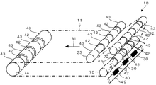
図9は、支持ローラである駆動ローラ72、クリーニング対向ローラ74、張架ローラ75、33と、光学センサ30と、転写ベルト11との相対位置関係を示している。同図においては、支持ローラのうち対向ローラである張架ローラ75を除くローラであるその他のローラを符号41で示している。よって、同図(a)にのみ張架ローラ75が示されており、同図(b)には他のローラ41が示されている。
FIG. 9 shows the relative positional relationship among the driving
同図に示されているように、張架ローラ75及びその他のローラ41は、領域MAに対応して、その他の部分より小径で転写ベルト11の裏面から離間した小径部42を有しているとともに、領域MBに対応して、かかるその他の部分として、小径部42より大径で転写ベルト11の裏面に当接する基本径部43と、小径部42と基本径部43との間に位置し、小径部42と基本径部43とに段差なく滑らかに連続して形成され小径部42に向けて径が漸減する傾斜部44とを有している。
As shown in the figure, the
領域MAに対応した張架ローラ75の小径部42の直径d1は、領域MBに対応した張架ローラ75の基本径部43の直径D1より小さく設定されており、領域MAに対応したその他のローラ41の小径部42の直径d2は、領域MBに対応したその他のローラ41の基本径部43の直径D2より小さく設定されている。
The diameter d1 of the
このように、張架ローラ75及びその他のローラ41の、領域MAに対応する部分は、凹状に形成されて、小径部42を形成している。ローラ直径を小さく設定する深さw1は、転写ベルト11の、張架ローラ75及びその他のローラ41の小径部42への接触が確実に回避される深さとされ、具体的には0.07[mm]とされている。このため、転写ベルト11の領域MAに対応する部分の裏面は張架ローラ75及びその他のローラ41の周面に接触しない構成となっている。その結果、領域MAにおいて張架ローラ75及びその他のローラ41への巻き付きによって転写ベルト11にかかるテンションは、領域MBにおいて張架ローラ75及びその他のローラ41への巻き付きによって転写ベルト11にかかるテンションと比べて小さくなるため、転写ベルト11には、その幅方向において小径部42に対応する部分すなわち領域MAに対応する部分においてカール癖がつきづらくなる。
As described above, portions of the stretching
傾斜部44は、製造過程において基本径部43の端部すなわちエッジの面取りを行うことで形成されており、その表面がカット面となっている。このように面取りを施すことで傾斜部44を設けることにより、基本径部43のエッジ部が転写ベルト11の裏面と擦れて傷が生じ転写ベルト11が劣化することを防止する。とくに、転写ベルト11を高湿環境下に長時間放置すると、かかるエッジ部に対応する位置において副走査方向に縦スジ状のベルト癖が生じる場合があるが、傾斜部44を形成することで、このような場合でも、カール癖やベルト癖を発生しにくくする。傾斜部44は、主走査方向に平行な断面においてカット面が直線をなすように形成されているが、曲面をなすように形成されていても良く、この場合はとくにカット面が凸形状をなすようになっていると、基本径部43とよく滑らかに連続するため好ましい。傾斜部44は少なくとも基本径部43と連続していればよく、小径部42との間には、図9に示した小径部42と別の、基本径部43より小径で転写ベルト11の裏面から離間した部分が介在していても良い。
The
図10に示しているように、転写ベルト11を懸架しているすべてのローラ72、74、75、33において、領域MAに対応するローラ直径すなわち小径部42の直径d1、d2を、領域MBに対応するローラ直径すなわち基本径部の直径D1、D2より小さくするため、すべてのローラ72、74、75、33において領域MAに対応する部分でカール癖が抑制され、その結果、転写ベルト11の1周すべての位置に対して、すなわち転写ベルト11の全周にわたって、光学センサ30の出力変動が低減される。
As shown in FIG. 10, in all the
たとえば、張架ローラ75と転写ベルト11の裏面との間にゴミなどが挟まることに起因して光学センサ30の出力にノイズが現れる現象を防止する手法として、光学センサ30が対向配置してある対向ローラである張架ローラ75にのみ小径部42を設ける構成が採られた場合、その副次的な作用として、張架ローラ75で発生するカール癖の影響が低減され得るが、その他のローラ41で発生するカール癖については、何ら低減されない(後述するように、その他のローラ41の径が大きい場合や表面弾性が大きい場合を除く)。その結果、他のローラ41で生じたカール癖が、転写ベルト11の駆動によって光学センサ30との対向位置まで移動してきた場合、光学センサ30の出力変動が生じることになる。
For example, as a technique for preventing a phenomenon in which noise appears in the output of the
これに対し、転写ベルト11を懸架しているすべてのローラ72、74、75、33において、領域MAに対応して小径部42を設けることで、転写ベルト11の全周にわたってカール癖が抑制されて、かかる出力変動が大きく抑制され、光学センサ30と転写ベルト11との位置関係の変化が抑制される。よって、Centerの光学センサ30おいては、階調パターンを構成するトナーパターンの濃度検知が精度良く保たれ、プロセスコントロールが良好に行われて、経時的に画像濃度が安定し、良好な画像形成が行われる。また、Front、Rearの光学センサ30においては、色ずれ補正制御等を目的とした位置ズレ補正制御が良好に行われ、色ずれや画像形成位置のずれが抑制されて、良好な画像形成が行われる。以上のことは、傾斜部44を設けることによってより高度に実現されている。
On the other hand, by providing the small-
なお、図10においては、ローラ72、74、75、33の形状の理解の容易のため、転写ベルト11を透視した状態で作図している。また、ローラ72、74、75、33の形状、大きさは、模式的に示したものであり、傾斜部44の図示を省略している他、小径部42、基本形部43の位置、径、幅などは必ずしも正確でない。これは図13においても同様である。また、他の図においても、ローラ72、74、75、33の形状、大きさは、模式的に示したものであり、各部の位置や大きさなどは必ずしも正確でない。
In FIG. 10, for easy understanding of the shapes of the
転写ベルト11の幅方向において、ローラ72、74、75、33に形成されているすべての小径部42の幅は、光学センサ30による検知領域の幅以上に設定されている。光学センサ30の検知領域幅は光学センサ30のスポット径すなわちLED36によって照射された光によって転写ベルト11の表面に形成される光の照射径と、正反射光受光素子37、拡散反射光受光素子38の取り付け公差によって決定され、光学センサ30、具体的には正反射光受光素子37、拡散反射光受光素子38が検知し得る範囲の幅、すなわち有効検知幅である。
In the width direction of the
小径部42の幅をかかる検知領域幅より小さく設定すると、光学センサ30の検知範囲内にカール癖が生じた部分が入り、光学センサ30の出力変動が生じることとなり得る。また、上述した縦スジ状のベルト癖が生じたとすると、光学センサ30の検知範囲にそのベルト癖部分が入ることになり、安定して検知が行えない。とくに、対向ローラである張架ローラ75の小径部42の幅L1(図9参照)をかかる検知領域幅より小さく設定すると、基本径部43のエッジ部に対応する転写ベルト11の表面を光学センサ30で検知することになり、光学センサ30による検知対象面の平面性が不安定となりやすく、安定した検知を行われなくなり得る。そのため、安定して検知を行うべく、支持ローラであるローラ72、74、75、33のうち、少なくとも対向ローラである張架ローラ75の小径部42の幅L1はかかる検知領域幅以上とする。
If the width of the small-
支持ローラであるローラ72、74、75、33に設ける、同一の領域MAに対応して設ける小径部42の幅は、ローラ72、74、75、33のそれぞれですべて互いに異なる幅とされている。かかる小径部42の幅が同じであると、ローラ72、74、75、33のそれぞれにおいて、基本径部43のエッジ部と転写ベルト11の裏面とが、転写ベルト11の幅方向において常に同じ位置で接することとなるため、転写ベルト11に副走査方向に沿って傷が付きやすくなり、異常画像の発生や転写ベルト11の破損などの不具合が生じ得る。しかし、ローラ72、74、75、33のそれぞれで小径部42の幅を異なる長さに設定しておけば、基本径部43のエッジ部と転写ベルト11の裏面とが接する位置がローラ72、74、75、33のそれぞれでずれるため、かかる不具合が起こりにくくなる。
The widths of the small-
この場合、対向ローラである張架ローラ75に設ける小径部42の幅L1を他のローラ41の小径部42の幅L2(図9参照)と比較して最も狭くすることが望ましく、画像形成装置100ではそのようになっている。張架ローラ75に設ける小径部42の幅L1を大きく設定するとすれば、転写ベルト11と張架ローラ75との非接触部分が拡大することとなる。その結果、かかる非接触部でベルトがたるみやすくなり、転写ベルト11の回転駆動時に転写ベルト11の波打ち言い換えるとばたつきの現象が発生することがある。この現象は、他のローラ41に巻き掛けられている部分で発生しても問題ないが、対向ローラである張架ローラ75に巻き掛けられている部分で発生すると、かかる波打ち、ばたつきは、光学センサ30の出力波形にノイズを発生させ、検知精度が低下することになる。
In this case, it is desirable that the width L1 of the small-
しかし、対向ローラである張架ローラ75に設ける小径部42の幅L1を他のローラ41の小径部42の幅L2(図9参照)と比較して最も狭くしているため、かかる現象に起因する光学センサ30の出力変動が抑制され、またこれと同時に、基本径部43のエッジ部に対応する部分で転写ベルト11に傷が生じても、この傷に対応する部分は光学センサ30の検知領域内に入らなくなることで、より安定した検知が行われる。ただし、対向ローラである張架ローラ75に設ける小径部42の幅L1は、光学センサ30の検知幅以上とする。
However, the width L1 of the small-
他のローラ41における、小径部42の幅L2は、その径具体的にはその直径D2に応じて設定されている。より具体的には、直径D2が小さいほど、幅L2は大きく設定されている。この理由を以下述べる。カール癖は直径D2が小さいほど、強く発生する。これは転写ベルト11が直径D2が小さいほどそのローラにより巻き付くようになって、転写ベルト11に加わる力が大きくなり、変形しやすくなるためである。そのため、直径D2が小さいほどカール癖がつきにくくなるように幅L2を設定する必要がある。一方、幅L2を大きくすると、転写ベルト11とローラ41との非接触部が大きくなるため、転写ベルト11がローラ41に引っ張られる力が低下し、転写ベルト11の伸び量が少なくなる。その結果、転写ベルト11にカール癖がつきにくくなり、光学センサ30の出力変動が低減することとなる。
The width L2 of the
そこで、他のローラ41における、小径部42の幅L2は、直径D2が小さいほど大きく設定されている。これにより、カール癖が強く発生しやすいローラについても、カール癖をつきにくくなるようにすることが可能となる。
Therefore, the width L2 of the
これを図示すると図11のようになる。同図は他のローラ41と、転写ベルト11との部分正面図であり、他のローラ41の直径D2に対する小径部42の幅L2の設定について示している。同図(a)と同図(b)との比較で分かるように、直径D4が直径D3より小さい場合には小径部42の幅L4を幅L3より大きく設定している。このように、直径D2に応じての幅L2を変更することで、よりカール癖をつきにくくすることが可能となる。
This is illustrated in FIG. This figure is a partial front view of the other roller 41 and the
図12は本方式すなわち小径部42を設けた場合と、従来方式すなわち基本径部43のみを有し小径部42を設けない場合とについて、転写ベルト11を高湿環境下に長時間放置し、転写ベルト11にカール癖をつけて光学センサ30で検知した結果を示している。なお、同図は本方式と従来方式とがそれぞれ見やすいように、それぞれの波形をオフセットさせて表示したものである。なお、小径部42は、支持ローラであるローラ72、74、75、33のすべてに設けている。
FIG. 12 shows a case where the present method, that is, the case where the
同図から明らかなように、本方式を用いた場合、転写ベルト11の全周の全ての位置でカール癖の影響が小さく、光学センサ30の出力変動が低減していることがわかる。このように、小径部42を設けると、カール癖による影響が抑制される。
As can be seen from the figure, when this method is used, the influence of curl wrinkles is small at all positions on the entire circumference of the
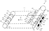
以上の説明においては、他のローラ41であるローラ72、75、33のすべてに小径部42を設けたが、以下のような場合には必ずしも他のローラ41であるローラ72、75、33のすべてに小径部42を設ける必要はない。たとえば、転写ベルト11は支持ローラである複数のローラ72、74、75、33によって懸架されているが、他のローラ41であるローラ72、75、33には直径が大きいものや、金属ローラにゴムなどの弾性率の低い材料をコートしたものが使用される場合がある。支持ローラであるローラ72、74、75、33の直径が十分に大きい場合には、転写ベルト11がこれらローラ72、74、75、33に巻き付く角度が小さく、転写ベルト11に加わる力は小さい。また、弾性率の低い材料がコートされている場合、コート層が変形するため転写ベルト11に加えられる力が小さくなる。
In the above description, the
したがって、支持ローラである複数のローラ72、74、75、33のうち、対向ローラである張架ローラ75と異なる他のローラ41であるローラ72、75、33については、その径の大小と、その表面弾性の大小とを条件として小径部42を設けるか否かを決め、その径が大きいとき、その表面弾性が大きいときには小径部42を有していない構成としても良い。対向ローラである駆動ローラ72については、光学センサ30の出力変動を抑制するため、小径部42を設ける。
Therefore, among the plurality of
図13に具体例を示す。この例においては、他のローラ41である駆動ローラ72の直径が十分に大きく、領域MAに対応する部分を小径としなくてもカール癖の影響は小さい。そのため、駆動ローラ72については、小径部42を設けていない。同様に、弾性率の低い材料をコートしたローラも、カール癖の影響が小さいため、小径部を設けないようにしてもよい。もちろん、小径部を設けて、よりカール癖の影響が小さくなるようにすることも可能である。直径がどの程度大きければ、また表面弾性がどの程度大きければ、小径部42を設けないこととするかは、転写ベルト11の材質等によって適宜決定される事項である。また、小径部42を設けるか否かを決定する条件としては、径と表面弾性との何れか一方を用いても良いし、これらの両方を用いる場合には、径の大きさの程度と表面弾性の大きさの程度とのバランスを勘案しその組み合わせに応じて適宜小径部42を設けるか否かが決定される。
A specific example is shown in FIG. In this example, the diameter of the driving
このように、支持ローラである複数のローラ72、74、75、33であっても、対向ローラである張架ローラ75と異なる他のローラ41であるローラ72、74、33については、小径部42が設けられない場合がある。言い換えると、支持ローラである複数のローラ72、74、75、33のうち少なくとも対向ローラである張架ローラ75は、小径部42を有する。
As described above, even if the plurality of
また、上述のように、小径部42の幅を異ならせるのは、支持ローラであるローラ72、74、75、33のうちの複数が小径部42を有する場合、すなわち対向ローラである張架ローラ75の他に小径部42を有する場合である。同様に、対向ローラである張架ローラ75に備えられた小径部42の幅L1を、他のローラ41に備えられた小径部42の幅L2より小さくするのも、支持ローラであるローラ72、74、75、33のうちの複数が小径部42を有する場合、すなわち対向ローラである張架ローラ75の他に小径部42を有する場合である。また、他のローラ41に備えられた小径部42の幅L2を、そのローラの径D2に応じて設定するのは、他のローラ41であるローラ72、75、33の少なくとも1つに小径部42が設けられる場合である。
Further, as described above, the width of the small-
以上本発明の好ましい実施の形態について説明したが、本発明はかかる特定の実施形態に限定されるものではなく、上述の説明で特に限定していない限り、特許請求の範囲に記載された本発明の趣旨の範囲内において、種々の変形・変更が可能である。 The preferred embodiments of the present invention have been described above. However, the present invention is not limited to the specific embodiments, and the present invention described in the claims is not specifically limited by the above description. Various modifications and changes are possible within the scope of the above.
たとえば、無端状のベルトを掛け渡す複数のローラは、対向ローラのほかに少なくとも1つ備えられていれば良い。無端状のベルトは、そのベルト上の像を光学的に検知手段によって検知されるものであれば、中間転写体でなく感光体等の静電潜像を形成される部材であっても良い。無端状のベルトは、検知手段によって光学的に検知される像を担持する点において、像担持体として機能する部材である。この像担持体が担持する像は、トナー像でなくインク等の他の画像形成物質によって形成された像であっても良い。 For example, it is only necessary that at least one roller that spans the endless belt is provided in addition to the opposing roller. The endless belt may be a member that forms an electrostatic latent image such as a photosensitive member instead of an intermediate transfer member as long as an image on the belt is optically detected by a detecting unit. The endless belt is a member that functions as an image carrier in that it carries an image optically detected by the detection means. The image carried by the image carrier may be an image formed of another image forming material such as ink instead of a toner image.
かかる条件を満たせば、本発明を適用する画像形成装置は、タンデム型であっても、上述した間接転写方式でなく、直接転写方式を採用可能である。また、画像形成装置は、いわゆるタンデム方式の画像形成装置ではなく、1つの感光体ドラム上に順次各色のトナー像を形成して各色トナー像を順次重ね合わせてカラー画像を得るいわゆる1ドラム方式の画像形成装置にも同様に適用することが可能であるし、他にも、シート状の有機感光体等の像担持体上に各色のトナー像を現像するものの色重ね自体は別にある中間転写体を用いる方式、あるいは中間転写体を複数用いる方式、中間色トナーを用いる方式等の画像形成装置にも同様に適用することが可能である If these conditions are satisfied, an image forming apparatus to which the present invention is applied can adopt a direct transfer method instead of the indirect transfer method described above, even if it is a tandem type. The image forming apparatus is not a so-called tandem type image forming apparatus, but a so-called one-drum type image forming apparatus that sequentially forms toner images of respective colors on a single photosensitive drum and sequentially superimposes the color toner images to obtain a color image. The intermediate transfer member can be applied to the image forming apparatus in the same manner, and in addition, the toner image of each color is developed on an image carrier such as a sheet-like organic photoreceptor, but the color superposition itself is separate. The present invention can also be applied to image forming apparatuses such as a method using a toner, a method using a plurality of intermediate transfer members, and a method using intermediate color toner.
その他、画像形成装置は、近年では、市場からの要求にともない、カラー複写機やカラープリンタなど、カラーのものが多くなってきているが、画像形成装置は、モノカラー画像のみを形成可能なものであっても良い。
このような画像形成装置に用いる画像形成物質として現像剤を用いる場合、この現像剤は、二成分現像剤に限らず、一成分現像剤であっても良い。
In addition, in recent years, in accordance with demands from the market, color image forming apparatuses, such as color copiers and color printers, have increased in number, but image forming apparatuses can only form monocolor images. It may be.
When a developer is used as an image forming material used in such an image forming apparatus, the developer is not limited to a two-component developer but may be a one-component developer.
画像形成装置は、複写機、プリンタ、ファクシミリの複合機でなく、これらの単体であっても良いし、その他、複写機とプリンタとの複合機等の他の組み合わせの複合機であっても良い。 The image forming apparatus may not be a copier, a printer, and a facsimile machine, but may be a single unit thereof, or may be a multi-function machine of another combination such as a copier and printer. .
本発明の実施の形態に記載された効果は、本発明から生じる最も好適な効果を列挙したに過ぎず、本発明による効果は、本発明の実施の形態に記載されたものに限定されるものではない。 The effects described in the embodiments of the present invention are only the most preferable effects resulting from the present invention, and the effects of the present invention are limited to those described in the embodiments of the present invention. is not.
11 無端状のベルト
30 検知手段
33、72、74、75 複数のローラ
33、72、74 その他のローラ
42 小径部
43 ベルトに当接する部分
44 傾斜部
75 対向ローラ
100 画像形成装置
D1、D2、D3、D4 ローラの径
L1、L2、L3、L4 小径部の幅
MA 無端状のベルトに像が担持される領域
DESCRIPTION OF
Claims (14)
前記ベルト上の像を光学的に検知する検知手段とを有し、
前記複数のローラは、前記ベルトを挟んで前記検知手段が対向した対向ローラと、その他のローラとからなり、
前記複数のローラのうち少なくとも前記対向ローラは、前記ベルトの幅方向における、前記検知手段によって検知される像が担持される領域に対応して、その他の部分より小径の小径部を有し、前記複数のローラのうち前記小径部を有するローラを複数有し、
前記幅方向において、前記小径部の幅を、同小径部を有するそれぞれのローラで互いに異ならせたことを特徴とする画像形成装置。 An endless belt stretched around a plurality of rollers;
Detecting means for optically detecting an image on the belt;
The plurality of rollers includes an opposing roller facing the detection means across the belt, and other rollers,
At least the opposing roller of the plurality of rollers, in the width direction of the belt, corresponding to the region where the image is carried is detected by the detection means, have a small diameter portion of the smaller diameter than the other portions, the It has a plurality of rollers having the small diameter portion among a plurality of rollers,
2. An image forming apparatus according to claim 1, wherein in the width direction, the width of the small diameter portion is made different between the rollers having the same small diameter portion .
前記ベルト上の像を光学的に検知する検知手段とを有し、
前記複数のローラは、前記ベルトを挟んで前記検知手段が対向した対向ローラと、その他のローラとからなり、
前記複数のローラのうち少なくとも前記対向ローラは、前記ベルトの幅方向における、前記検知手段によって検知される像が担持される領域に対応して、その他の部分より小径の小径部を有し、前記複数のローラのうち前記小径部を有するローラを複数有し、
前記幅方向において、前記対向ローラに備えられた前記小径部の幅を、他のローラに備えられた前記小径部の幅より小さくしたことを特徴とする画像形成装置。 An endless belt stretched around a plurality of rollers;
Detecting means for optically detecting an image on the belt;
The plurality of rollers includes an opposing roller facing the detection means across the belt, and other rollers,
At least the counter roller of the plurality of rollers has a small diameter portion smaller in diameter than other portions corresponding to a region in which the image detected by the detection means is carried in the width direction of the belt, It has a plurality of rollers having the small diameter portion among a plurality of rollers,
In the width direction, an image forming apparatus characterized in that a width of the small diameter portion provided in the counter roller is smaller than a width of the small diameter portion provided in another roller .
前記ベルト上の像を光学的に検知する検知手段とを有し、
前記複数のローラは、前記ベルトを挟んで前記検知手段が対向した対向ローラと、その他のローラとからなり、
前記複数のローラのうち少なくとも前記対向ローラは、前記ベルトの幅方向における、前記検知手段によって検知される像が担持される領域に対応して、その他の部分より小径の小径部を有し、前記複数のローラのうち前記小径部を有するローラを複数有し、
前記幅方向における、前記対向ローラと異なるローラに備えられた前記小径部の幅を、当該ローラの径に応じて設定したことを特徴とする画像形成装置。 An endless belt stretched around a plurality of rollers;
Detecting means for optically detecting an image on the belt;
The plurality of rollers includes an opposing roller facing the detection means across the belt, and other rollers,
At least the counter roller of the plurality of rollers has a small diameter portion smaller in diameter than other portions corresponding to a region in which the image detected by the detection means is carried in the width direction of the belt, It has a plurality of rollers having the small diameter portion among a plurality of rollers,
An image forming apparatus , wherein a width of the small-diameter portion provided in a roller different from the facing roller in the width direction is set according to a diameter of the roller .
前記ベルト上の像を光学的に検知する検知手段とを有し、
前記複数のローラは、前記ベルトを挟んで前記検知手段が対向した対向ローラと、その他のローラとからなり、
前記複数のローラのうち少なくとも前記対向ローラは、前記ベルトの幅方向における、前記検知手段によって検知される像が担持される領域に対応して、その他の部分より小径の小径部を有し、前記複数のローラのうち前記小径部を有するローラを複数有し、
前記幅方向における、前記対向ローラと異なるローラに備えられた前記小径部の幅を、当該ローラの径に応じて設定し、前記幅方向における、前記対向ローラと異なるローラに備えられた前記小径部の幅を、当該ローラの径が小さいほど、大きく設定したことを特徴とする画像形成装置。 An endless belt stretched around a plurality of rollers;
Detecting means for optically detecting an image on the belt;
The plurality of rollers includes an opposing roller facing the detection means across the belt, and other rollers,
At least the counter roller of the plurality of rollers has a small diameter portion smaller in diameter than other portions corresponding to a region in which the image detected by the detection means is carried in the width direction of the belt, It has a plurality of rollers having the small diameter portion among a plurality of rollers,
The width of the small diameter portion provided in a roller different from the facing roller in the width direction is set according to the diameter of the roller, and the small diameter portion provided in a roller different from the facing roller in the width direction. The image forming apparatus is characterized in that the width is set to be larger as the diameter of the roller is smaller .
前記ベルト上の像を光学的に検知する検知手段とを有し、
前記複数のローラは、前記ベルトを挟んで前記検知手段が対向した対向ローラと、その他のローラとからなり、
前記複数のローラのうち少なくとも前記対向ローラは、前記ベルトの幅方向における、前記検知手段によって検知される像が担持される領域に対応して、その他の部分より小径の小径部を有し、前記複数のローラのうち前記対向ローラと異なるローラは、その径の大小を条件として前記小径部を設けるか否かが決められており、その径が大きいときには前記小径部を有していないことを特徴とする画像形成装置。 An endless belt stretched around a plurality of rollers;
Detecting means for optically detecting an image on the belt;
The plurality of rollers includes an opposing roller facing the detection means across the belt, and other rollers,
At least the counter roller of the plurality of rollers has a small diameter portion smaller in diameter than other portions corresponding to a region in which the image detected by the detection means is carried in the width direction of the belt, Of the plurality of rollers, a roller different from the facing roller is determined whether or not the small diameter portion is provided on the condition that the diameter is large, and when the diameter is large, the small diameter portion is not provided. An image forming apparatus.
前記ベルト上の像を光学的に検知する検知手段とを有し、
前記複数のローラは、前記ベルトを挟んで前記検知手段が対向した対向ローラと、その他のローラとからなり、
前記複数のローラのうち少なくとも前記対向ローラは、前記ベルトの幅方向における、前記検知手段によって検知される像が担持される領域に対応して、その他の部分より小径の小径部を有し、前記複数のローラのうち前記対向ローラと異なるローラは、その表面弾性を条件として前記小径部を設けるか否かが決められており、その表面弾性が大きいときには前記小径部を有していないことを特徴とする画像形成装置。 An endless belt stretched around a plurality of rollers;
Detecting means for optically detecting an image on the belt;
The plurality of rollers includes an opposing roller facing the detection means across the belt, and other rollers,
At least the counter roller of the plurality of rollers has a small diameter portion smaller in diameter than other portions corresponding to a region in which the image detected by the detection means is carried in the width direction of the belt, Of the plurality of rollers, a roller different from the facing roller is determined whether or not the small diameter portion is provided on the condition of the surface elasticity, and when the surface elasticity is large, the small diameter portion is not provided. An image forming apparatus.
前記幅方向において、前記小径部の幅を、前記検知手段の検知領域の幅以上としたことを特徴とする画像形成装置。 The image forming apparatus according to any one of claims 1 to 6,
In the width direction, the width of the small-diameter portion is equal to or larger than the width of the detection area of the detection unit.
前記複数のローラのうち前記小径部を有するローラを複数有し、前記幅方向において、前記小径部の幅を、同小径部を有するそれぞれのローラで互いに異ならせたことを特徴とする画像形成装置。 The image forming apparatus according to any one of claims 2 to 7,
An image forming apparatus comprising: a plurality of rollers having the small diameter portion among the plurality of rollers, wherein the width of the small diameter portion is different among the rollers having the same small diameter portion in the width direction. .
前記複数のローラのうち前記小径部を有するローラを複数有し、
前記幅方向において、前記対向ローラに備えられた前記小径部の幅を、他のローラに備えられた前記小径部の幅より小さくしたことを特徴とする画像形成装置。 The image forming apparatus according to any one of claims 1, 3 to 8 ,
A plurality of rollers having the small diameter portion among the plurality of rollers;
In the width direction, an image forming apparatus characterized in that a width of the small diameter portion provided in the counter roller is smaller than a width of the small diameter portion provided in another roller .
前記複数のローラのうち前記小径部を有するローラを複数有し、
前記幅方向における、前記対向ローラと異なるローラに備えられた前記小径部の幅を、当該ローラの径に応じて設定したことを特徴とする画像形成装置。 The image forming apparatus according to any one of claims 1, 2, 5 to 9 ,
A plurality of rollers having the small diameter portion among the plurality of rollers;
An image forming apparatus , wherein a width of the small-diameter portion provided in a roller different from the facing roller in the width direction is set according to a diameter of the roller .
前記複数のローラのうち前記小径部を有するローラを複数有し、 A plurality of rollers having the small diameter portion among the plurality of rollers;
前記幅方向における、前記対向ローラと異なるローラに備えられた前記小径部の幅を、当該ローラの径が小さいほど、大きく設定したことを特徴とする画像形成装置。 The image forming apparatus according to claim 1, wherein the width of the small-diameter portion provided in a roller different from the facing roller in the width direction is set larger as the diameter of the roller is smaller.
前記複数のローラのうち前記小径部を有するローラは、前記幅方向において、前記ベルトに当接する部分と前記小径部との間に、同部分に連続して形成され前記小径部に向けて径が漸減する傾斜部を有することを特徴とする画像形成装置。 Among the plurality of rollers, the roller having the small diameter portion is formed continuously between the portion in contact with the belt and the small diameter portion in the width direction and has a diameter toward the small diameter portion. An image forming apparatus having an inclined portion that gradually decreases.
前記複数のローラのうち前記対向ローラと異なるローラは、その径の大小を条件として前記小径部を設けるか否かが決められており、その径が大きいときには前記小径部を有していないことを特徴とする画像形成装置。 Of the plurality of rollers, a roller different from the counter roller is determined whether or not to provide the small diameter portion on condition that the diameter is large, and when the diameter is large, the roller does not have the small diameter portion. An image forming apparatus.
前記複数のローラのうち前記対向ローラと異なるローラは、その表面弾性を条件として前記小径部を設けるか否かが決められており、その表面弾性が大きいときには前記小径部を有していないことを特徴とする画像形成装置。 Of the plurality of rollers, a roller different from the opposing roller is determined as to whether or not the small diameter portion is provided on the condition of the surface elasticity, and when the surface elasticity is large, the roller does not have the small diameter portion. An image forming apparatus.
Priority Applications (1)
| Application Number | Priority Date | Filing Date | Title |
|---|---|---|---|
| JP2010192585A JP5533449B2 (en) | 2010-08-30 | 2010-08-30 | Image forming apparatus |
Applications Claiming Priority (1)
| Application Number | Priority Date | Filing Date | Title |
|---|---|---|---|
| JP2010192585A JP5533449B2 (en) | 2010-08-30 | 2010-08-30 | Image forming apparatus |
Publications (2)
| Publication Number | Publication Date |
|---|---|
| JP2012048147A JP2012048147A (en) | 2012-03-08 |
| JP5533449B2 true JP5533449B2 (en) | 2014-06-25 |
Family
ID=45903052
Family Applications (1)
| Application Number | Title | Priority Date | Filing Date |
|---|---|---|---|
| JP2010192585A Expired - Fee Related JP5533449B2 (en) | 2010-08-30 | 2010-08-30 | Image forming apparatus |
Country Status (1)
| Country | Link |
|---|---|
| JP (1) | JP5533449B2 (en) |
Families Citing this family (1)
| Publication number | Priority date | Publication date | Assignee | Title |
|---|---|---|---|---|
| JP6948585B2 (en) * | 2016-05-16 | 2021-10-13 | 株式会社リコー | Image forming apparatus, image forming system and image forming method |
Family Cites Families (5)
| Publication number | Priority date | Publication date | Assignee | Title |
|---|---|---|---|---|
| JPH10104898A (en) * | 1996-09-30 | 1998-04-24 | Ricoh Co Ltd | Carrying belt unit for image forming device |
| JP4015107B2 (en) * | 2003-12-22 | 2007-11-28 | 株式会社リコー | Image forming apparatus |
| JP5103967B2 (en) * | 2007-03-20 | 2012-12-19 | 富士ゼロックス株式会社 | Image forming apparatus |
| JP5428168B2 (en) * | 2008-03-04 | 2014-02-26 | 株式会社リコー | Image forming apparatus |
| JP2009276686A (en) * | 2008-05-16 | 2009-11-26 | Ricoh Co Ltd | Image forming apparatus |
-
2010
- 2010-08-30 JP JP2010192585A patent/JP5533449B2/en not_active Expired - Fee Related
Also Published As
| Publication number | Publication date |
|---|---|
| JP2012048147A (en) | 2012-03-08 |
Similar Documents
| Publication | Publication Date | Title |
|---|---|---|
| US8457516B2 (en) | Image forming apparatus and method using an environment detector which changes a test toner image based on a detection result | |
| JP5240579B2 (en) | Image forming apparatus | |
| US8391759B2 (en) | Belt device, belt deviation detecting device, and image forming apparatus | |
| US9977361B2 (en) | Image forming apparatus and image forming system | |
| US20070053703A1 (en) | Image forming apparatus | |
| US8369725B2 (en) | Image forming apparatus and method of correcting image concentration | |
| US7881636B2 (en) | Belt driving device and image forming apparatus | |
| JP2011209674A (en) | Image forming apparatus and image forming method | |
| JP2012194384A (en) | Image forming apparatus and method for controlling image density | |
| US8417132B2 (en) | Image forming apparatus | |
| JP2014132318A (en) | Image forming apparatus | |
| JP5382519B2 (en) | Image forming apparatus | |
| US9442420B2 (en) | Image forming apparatus and image forming method | |
| JP2008020818A (en) | Image forming apparatus and image stabilization method | |
| JP2011090116A (en) | Image-forming device and image-forming method | |
| US9146498B2 (en) | Image forming apparatus | |
| US9958811B2 (en) | Image forming apparatus having transfer belt | |
| JP2009042375A (en) | Image forming device | |
| JP5533449B2 (en) | Image forming apparatus | |
| JP2012247627A (en) | Image forming device | |
| US20150220032A1 (en) | Image forming apparatus | |
| JP5760518B2 (en) | Image forming apparatus and image control method | |
| US20120251194A1 (en) | Image forming apparatus | |
| JP2005266686A (en) | Image forming apparatus | |
| JP2003228245A (en) | Image forming apparatus |
Legal Events
| Date | Code | Title | Description |
|---|---|---|---|
| A621 | Written request for application examination |
Free format text: JAPANESE INTERMEDIATE CODE: A621 Effective date: 20130621 |
|
| A977 | Report on retrieval |
Free format text: JAPANESE INTERMEDIATE CODE: A971007 Effective date: 20131225 |
|
| A131 | Notification of reasons for refusal |
Free format text: JAPANESE INTERMEDIATE CODE: A131 Effective date: 20140107 |
|
| A521 | Written amendment |
Free format text: JAPANESE INTERMEDIATE CODE: A523 Effective date: 20140310 |
|
| TRDD | Decision of grant or rejection written | ||
| A01 | Written decision to grant a patent or to grant a registration (utility model) |
Free format text: JAPANESE INTERMEDIATE CODE: A01 Effective date: 20140401 |
|
| R151 | Written notification of patent or utility model registration |
Ref document number: 5533449 Country of ref document: JP Free format text: JAPANESE INTERMEDIATE CODE: R151 |
|
| A61 | First payment of annual fees (during grant procedure) |
Free format text: JAPANESE INTERMEDIATE CODE: A61 Effective date: 20140414 |
|
| LAPS | Cancellation because of no payment of annual fees |