JP5531425B2 - Game machine - Google Patents
Game machine Download PDFInfo
- Publication number
- JP5531425B2 JP5531425B2 JP2009060691A JP2009060691A JP5531425B2 JP 5531425 B2 JP5531425 B2 JP 5531425B2 JP 2009060691 A JP2009060691 A JP 2009060691A JP 2009060691 A JP2009060691 A JP 2009060691A JP 5531425 B2 JP5531425 B2 JP 5531425B2
- Authority
- JP
- Japan
- Prior art keywords
- connection line
- hole
- gaming machine
- front door
- game
- Prior art date
- Legal status (The legal status is an assumption and is not a legal conclusion. Google has not performed a legal analysis and makes no representation as to the accuracy of the status listed.)
- Expired - Fee Related
Links
- 238000005192 partition Methods 0.000 claims description 16
- 230000002265 prevention Effects 0.000 claims description 14
- 230000000903 blocking effect Effects 0.000 claims description 13
- 230000004044 response Effects 0.000 claims description 2
- 238000003780 insertion Methods 0.000 description 16
- 230000037431 insertion Effects 0.000 description 16
- 238000010586 diagram Methods 0.000 description 12
- 238000000034 method Methods 0.000 description 9
- 238000004519 manufacturing process Methods 0.000 description 7
- 238000005034 decoration Methods 0.000 description 6
- 230000001681 protective effect Effects 0.000 description 6
- NIXOWILDQLNWCW-UHFFFAOYSA-N acrylic acid group Chemical group C(C=C)(=O)O NIXOWILDQLNWCW-UHFFFAOYSA-N 0.000 description 4
- 210000000078 claw Anatomy 0.000 description 4
- 230000000694 effects Effects 0.000 description 4
- 238000011084 recovery Methods 0.000 description 4
- 230000007274 generation of a signal involved in cell-cell signaling Effects 0.000 description 3
- 239000000463 material Substances 0.000 description 3
- 229920005989 resin Polymers 0.000 description 3
- 239000011347 resin Substances 0.000 description 3
- 239000000758 substrate Substances 0.000 description 3
- 230000008859 change Effects 0.000 description 2
- 239000002184 metal Substances 0.000 description 2
- 238000000638 solvent extraction Methods 0.000 description 2
- 241000287127 Passeridae Species 0.000 description 1
- 230000002238 attenuated effect Effects 0.000 description 1
- 230000005540 biological transmission Effects 0.000 description 1
- 238000012790 confirmation Methods 0.000 description 1
- 238000005286 illumination Methods 0.000 description 1
- 238000009434 installation Methods 0.000 description 1
- 238000002955 isolation Methods 0.000 description 1
- 239000004973 liquid crystal related substance Substances 0.000 description 1
- 230000007246 mechanism Effects 0.000 description 1
- NJPPVKZQTLUDBO-UHFFFAOYSA-N novaluron Chemical compound C1=C(Cl)C(OC(F)(F)C(OC(F)(F)F)F)=CC=C1NC(=O)NC(=O)C1=C(F)C=CC=C1F NJPPVKZQTLUDBO-UHFFFAOYSA-N 0.000 description 1
- 230000000149 penetrating effect Effects 0.000 description 1
- 230000035515 penetration Effects 0.000 description 1
- 239000004033 plastic Substances 0.000 description 1
- 239000004417 polycarbonate Substances 0.000 description 1
- 229920000515 polycarbonate Polymers 0.000 description 1
- 238000003825 pressing Methods 0.000 description 1
- 230000008569 process Effects 0.000 description 1
- 230000009467 reduction Effects 0.000 description 1
- 238000003860 storage Methods 0.000 description 1
- 229920003002 synthetic resin Polymers 0.000 description 1
- 239000000057 synthetic resin Substances 0.000 description 1
Images


Description
本発明は、スロットマシン等の遊技機、及び該遊技機に対する不正を防止する方法に関するものである。 The present invention relates to a gaming machine such as a slot machine and a method for preventing fraud against the gaming machine.
スロットマシン等の遊技機には、その前面扉に種々の部材が装着されており、このような装着部材の中には、ベットボタンやストップボタン等の複数の操作部材が含まれる。この操作部材は、操作頻度が高く故障が多いので、容易に交換を行うことができるように前面扉と別部材で構成され、着脱自在に取り付けられることが一般的である。例えば、特許文献1には、操作部材の一例であるベットボタンの取り付け構造が記載されている。この文献によれば、前面扉とは別体に形成されたベットボタンの両側部に爪部を形成し、このベットボタンを前面扉に設けられた貫通穴部に挿入して爪部を取り付け孔の縁部に係止させることで、ベットボタンの前面扉への取り付けを行なっている(文献1の図1、及び図2参照)。このベットボタン等の操作部材が操作された際、その操作に対する信号を遊技機内にある中継基板等の基板装置に送信する必要があるため、操作部材は、この基板装置と接続線により接続されている。
A gaming machine such as a slot machine has various members mounted on the front door thereof, and such mounting members include a plurality of operation members such as a bet button and a stop button. Since this operation member has a high operation frequency and many failures, it is generally configured as a separate member from the front door and detachably attached so that it can be easily replaced. For example,
一方、遊技機内には、遊技の都度変動表示されるリールの制御や大当たり抽選等を行う主制御基板、メダルの払い出し制御を行うホッパ基板、電源のオン・オフを管理する電源制御基板、レバーの操作による抽選関連の信号を生成する遊技信号生成装置等、遊技者の利益を左右する遊技関連装置が複数設けられている。 On the other hand, in the gaming machine, there are a main control board that performs reel control and big win lottery display, etc., a hopper board that performs payout control of medals, a power control board that manages power on / off, and levers. There are provided a plurality of game-related devices that influence the profit of the player, such as a game signal generation device that generates a lottery-related signal by operation.
近年では、前面扉と別体の操作部材が取外されている状態で空いた貫通穴部からの遊技関連装置への行為が行われることが問題となっていた。 In recent years, the act of Previous Mentobira separately from the operation member is detached and has a through hole or Rano遊 technique related apparatus vacant state is performed has been a problem.
本発明は、このような事情に鑑みてなされたものであり、その目的は、遊技機内の装置に不正にアクセスされることを防止できる遊技機を提供することにある。 The present invention has been made in view of such circumstances, and its object is to provide a gaming machine capable of preventing of unauthorized access to devices Yu technique machine.
上記課題を解決する請求項1に記載の発明による遊技機は、前面側に開口部を有する筐体と、該筐体の開口部に開閉可能に取り付けられ貫通穴部の形成された前面扉と、該前面扉の外側から前記貫通穴部に挿入装着される装着部材と、遊技機内部に設けられた遊技に関連する機能を有する遊技関連装置と、を備えた遊技機において、前記装着部材は、遊技機内部の配線接続先部材に接続させる複数のコネクタが先端に設けられて、前記各コネクタから延びる接続線を有する操作部材として構成され、前記前面扉には、前記接続線の通過を許容する接続線通過穴部を有するとともに、前記操作部材が装着されている前記貫通穴部と前記遊技関連装置との間を仕切る仕切り部材が設けられ、前記各接続線には、それぞれ引き出し防止部材が設けられ、一の接続線に設けられた前記引き出し防止部材は、前記接続線通過穴部とその断面形状及び面積が略同一であり、他の接続線に設けられた前記引き出し防止部材は、前記接続線通過穴部において前記一の接続線の接続線が通過している領域以外の領域とその断面形状及び面積が略同一であることを特徴とする。 A gaming machine according to the first aspect of the present invention that solves the above-described problem includes a housing having an opening on the front surface side, a front door that is attached to the opening of the housing so as to be openable and closable, and has a through hole. In the gaming machine, comprising: a mounting member that is inserted and mounted in the through hole portion from the outside of the front door; and a game-related device provided in the gaming machine and having a function related to a game. A plurality of connectors to be connected to the wiring connection destination member inside the gaming machine is provided at the tip, and is configured as an operation member having a connection line extending from each connector, and the front door is allowed to pass the connection line A partition member for partitioning between the through-hole portion in which the operation member is mounted and the game-related device is provided , and each connection line has a pull-out preventing member. Established The pull-out prevention member provided on one connection line has substantially the same cross-sectional shape and area as the connection line passage hole, and the pull-out prevention member provided on the other connection line includes the connection line. It is characterized in that the cross-sectional shape and area of the through hole portion other than the region through which the connection line of the one connection line passes are substantially the same .
本発明によれば、遊技機内の装置に不正にアクセスされることを防止できる According to the present invention, it can be prevented from being illegally accessed device Yu technique flight
はじめに、本実施の形態から抽出され得る発明群を手段n(n=0,1,2・・・)として区分して示し、それらを必要に応じて効果等を示しつつ説明する。First, invention groups that can be extracted from the present embodiment are shown as means n (n = 0, 1, 2,...), And will be described while showing effects and the like as necessary.
手段0.手段0の遊技機は、前前面側に開口部を有する筐体と、該筐体の開口部に開閉可能に取り付けられ貫通穴部の形成された前面扉と、該前面扉の外側から前記貫通穴部に挿入装着される装着部材と、遊技機内部に設けられた遊技に関連する機能を有する遊技関連装置と、を備えた遊技機において、前記装着部材は、遊技機内部の配線接続先部材に接続させる複数のコネクタが先端に設けられて、前記各コネクタから延びる接続線を有する操作部材として構成され、前記前面扉には、前記接続線の通過を許容する接続線通過穴部を有するとともに、前記操作部材が装着されている前記貫通穴部と前記遊技関連装置との間を仕切る仕切り部材が設けられ、前記各接続線には、それぞれ引き出し防止部材が設けられ、一の接続線に設けられた前記引き出し防止部材は、前記接続線通過穴部とその断面形状及び面積が略同一であり、他の接続線に設けられた前記引き出し防止部材は、前記接続線通過穴部において前記一の接続線の接続線が通過している領域以外の領域とその断面形状及び面積が略同一であることを特徴とする。Means 0. The gaming machine of the means 0 includes a housing having an opening on the front front side, a front door attached to the opening of the housing so as to be openable and closable and formed with a through hole, and the penetration from the outside of the front door. In a gaming machine comprising a mounting member inserted and mounted in the hole and a game-related device provided in the gaming machine and having a function related to a game, the mounting member is a wiring connection destination member inside the gaming machine A plurality of connectors to be connected to the front end, and configured as an operation member having a connection line extending from each connector, and the front door has a connection line passage hole portion that allows the connection line to pass therethrough. A partition member is provided for partitioning between the through-hole portion in which the operation member is mounted and the game-related device, and each connection line is provided with a pull-out prevention member, and is provided on one connection line. Said pull The connection preventing member is substantially the same in cross-sectional shape and area as the connection line passage hole, and the pullout prevention member provided on the other connection line is connected to the one connection line in the connection line passage hole. A region other than the region through which the connection line passes is substantially the same in cross-sectional shape and area.
手段1.手段1の遊技機は、前面側に開口部を有する筐体と、該筐体の開口部に開閉可能に取り付けられ貫通穴部の形成された前面扉と、該前面扉の外側から前記貫通穴部に挿入装着される装着部材と、遊技機内部に設けられた遊技に関連する機能を有する遊技関連装置と、を備えた遊技機において、前記前面扉には、前記装着部材が前記貫通穴部から取外された状態で、該貫通穴部を通した遊技機内への侵入を規制する侵入規制手段が設けられたことを特徴とする。
なお、遊技関連制御装置とは、主基板等の遊技の抽選に関連する制御を行う基板、抽選関連信号を生成するスタートレバー用信号生成装置などの抽選乱数の発生に係る装置、ホッパ基板等のメダルの払い出しに関連する制御を行う基板、及び遊技にかかる電気信号や電流の伝達媒体となる配線やそのコネクタなどの不正対象となり得るものを意味する。 The game-related control device is a board that performs control related to game lottery such as a main board, a device related to generation of random numbers such as a start lever signal generation device that generates a lottery-related signal, a hopper board, etc. It means a board that performs control related to the payout of medals, wiring that serves as a transmission medium for electric signals and currents related to games, and connectors thereof that can be fraudulent.
これにより、不正を行おうとする者によって装着部材が取外され、この装着部材が装着されていた部分の貫通穴部から針金等の不正な工具等が挿入された場合であっても、この貫通穴部からの遊技機内への侵入を規制する侵入規制手段により、不正な工具の侵入を規制することができ、上記遊技関連装置への不正なアクセスを防止することができる。 As a result, even if a mounting member is removed by a person who intends to cheat and an unauthorized tool or the like such as a wire is inserted from a through hole portion where the mounting member is mounted, The intrusion restricting means for restricting the intrusion into the gaming machine from the hole portion can restrict the intrusion of an unauthorized tool and prevent the unauthorized access to the game related device.
手段2.手段2の遊技機は、手段1の遊技機において、前記装着部材は、遊技機内部の配線接続先部材と接続線により接続される操作部材として構成され、前記侵入規制手段は、前記操作部材からの前記接続線の通過を許容する接続線通過穴部を残して、前記操作部材が装着されている前記貫通穴部と前記遊技関連装置との間を仕切る仕切り部材として構成されたことを特徴とする。Mean 2. The gaming machine of means 2 is the gaming machine of
遊技機の一例としてのスロットマシンの一般的な構成においては、ベットボタンやストップボタン等の操作部材が、遊技者などにより外側から操作される際の衝撃によって前面扉から脱離しないように、フランジ等の係合部材を用いて前面扉の外側から取り付けられている。このような取り付け状態の操作部材は、上記係合部材による前面扉への係合状態を解除することで前面扉の外側から容易に取外される。従って、当該操作部材は、特に、前面扉外側からの不正な取外しの対象となり易い。一方で、ベットボタンやストップボタンの近傍には、遊技における抽選関連信号を生成するスタートレバーが設けられている。この構成も、不正を試みる者が、ベットボタンやストップボタンを前面扉から不正に取外し、内部に工具を侵入させようとする試みを助長する要因となっている。In a general configuration of a slot machine as an example of a gaming machine, a flange is provided so that operation members such as a bet button and a stop button are not detached from the front door by an impact when operated from the outside by a player or the like. It attaches from the outer side of a front door using engaging members, such as. The operation member in such an attached state is easily detached from the outside of the front door by releasing the engagement state of the engagement member with the front door. Therefore, the operation member is particularly susceptible to unauthorized removal from the outside of the front door. On the other hand, a start lever for generating a lottery-related signal in the game is provided in the vicinity of the bet button and the stop button. This configuration also contributes to an attempt by an unauthorized person to remove a bet button or a stop button from the front door and cause a tool to enter inside.
手段2の構成によれば、侵入規制手段が、操作部材に接続されている配線接続先への接続線の通過を許容する接続線通過穴部を備え、この操作部材が装着されている貫通穴部と前記遊技関連装置との間を仕切る仕切り部材として構成されたことによって、特に不正な取外しが行われ易いベットボタンやストップボタン等の操作部材が挿入装着されている部分の貫通穴部と上記遊技関連装置との間を物理的に仕切り、遊技機内の遊技関連装置への不正なアクセスを防止することができる。According to the configuration of the means 2, the intrusion restricting means includes a connection line passage hole portion that allows the connection line to pass to the wiring connection destination connected to the operation member, and the through hole in which the operation member is mounted And the above-mentioned game-related device as a partition member, the through-hole portion of the portion where the operation member such as a bet button or a stop button is inserted and mounted, which is particularly likely to be illegally removed. It is possible to physically partition the game-related device and prevent unauthorized access to the game-related device in the gaming machine.
手段3.手段3の遊技機は、手段2の遊技機において、前記貫通穴部と前記接続線通過穴部を結ぶ方向と、該接続線通過穴部と前記遊技関連装置とを結ぶ方向が異なることを特徴とする。Means 3. The gaming machine of means 3 is characterized in that, in the gaming machine of means 2, the direction connecting the through hole portion and the connection line passage hole portion is different from the direction connecting the connection line passage hole portion and the game-related device. And
これによれば、前面扉における操作部材が挿入装着されている部分の貫通穴部、接続線通過穴部、及び遊技関連装置を結ぶ経路が非直線状となるので、不正を行おうとする者によって装着部材が取外され、この装着部材が装着されていた部分の貫通穴部から針金等の不正な工具等が挿入された場合であっても、この工具を、接続線通過穴部を経由して遊技関連装置に到達させることが困難なものとなる。従って、遊技関連装置への不正アクセスをより効果的に防止することができる。According to this, since the path connecting the through hole portion, the connecting wire passage hole portion, and the game-related device of the portion where the operation member in the front door is inserted and mounted becomes non-linear, by a person who intends to cheat Even when the mounting member is removed and an unauthorized tool such as a wire is inserted from the through-hole portion where the mounting member was mounted, this tool is passed through the connecting wire passage hole. Thus, it is difficult to reach the game-related device. Therefore, unauthorized access to the game-related device can be more effectively prevented.
手段4.手段4の遊技機は、手段2又は手段3に記載の遊技機において、前記仕切り部材は、板状の遮断板として構成されたことを特徴とする。これによれば、上記仕切り部材を、遮断板を設けるという容易な方法で構成することができる。Means 4. The gaming machine of means 4 is the gaming machine according to means 2 or 3, wherein the partition member is configured as a plate-shaped blocking plate. According to this, the said partition member can be comprised by the easy method of providing a shielding board.
手段5.手段5の遊技機は、手段2又は3に記載の遊技機において、前記仕切り部材は、前記操作部材の前記貫通穴部へ挿入された部分である操作部材被挿入部を覆う操作部カバー部材として構成されたことを特徴とする。Means 5. The gaming machine of the means 5 is the gaming machine according to the means 2 or 3, wherein the partition member is an operation portion cover member that covers an operation member insertion portion that is a portion inserted into the through hole portion of the operation member. It is structured.
これにより、不正を行おうとする者によって操作部材が取外され、この操作部材が装着されていた部分の貫通穴部から針金等の不正な工具等が挿入された場合であっても、操作部カバー部材により工具の侵入路が塞がれ、遊技機内の遊技関連装置へのアクセスを効果的に防止することができる。Thus, even if an operation member is removed by a person who intends to perform an unauthorized operation and an unauthorized tool such as a wire is inserted from a through-hole portion where the operation member is mounted, the operation unit The cover member blocks the entry path of the tool, and can effectively prevent access to the game-related device in the gaming machine.
手段6.手段6の遊技機は、手段5の遊技機において、前記操作部カバー部材の内部において前記接続線を通過させる経路が、非直線状に形成されたことを特徴とする。Means 6. The gaming machine of means 6 is characterized in that, in the gaming machine of means 5, the path through which the connection line passes is formed in a non-linear manner inside the operation portion cover member.
これによれば、仮に、不正を行おうとする者が、操作部材を取外して、その操作部材が装着されていた部分の貫通穴部から工具を挿入し、操作部カバー部材内部を通して接続線通過穴部から遊技機本体内の遊技関連装置にアクセスしようとした場合であっても、操作部カバー部材の内部における接続線の通過経路が非直線状であるので、上記工具の操作部カバー部材内における侵入経路も、非直線状となる。従って、工具を貫通穴部から接続線通過穴部に到達させることが困難なものとなり、遊技機内への遊技関連装置への不正なアクセスを効果的に防止することができる。According to this, if a person who intends to cheat removes the operation member, inserts the tool from the through hole portion of the portion where the operation member was mounted, and passes through the inside of the operation portion cover member, the connection line passage hole Even when trying to access a game-related device in the gaming machine main body from the section, since the passage path of the connection line inside the operation section cover member is non-linear, the tool in the operation section cover member The intrusion path is also non-linear. Therefore, it becomes difficult to allow the tool to reach the connecting line passage hole from the through hole, and illegal access to the game-related device in the gaming machine can be effectively prevented.
手段7.手段7の遊技機は、手段5又は6の遊技機において、前記操作部カバー部材は、前記操作部材の前記操作部材被挿入部、及び前記接続線を該操作部材被挿入部の部分から配線接続先部材の位置までに亘って共に覆う全体カバー部材として形成されたことを特徴とする。Mean 7 The gaming machine of
これによれば、操作部材の被挿入部分、及びその被挿入部分に設けられている接続線が、配線接続先部材の部分までに亘って全体的に覆われることとなり、操作部材が装着されている部分の貫通穴部と連通する遊技機内部の空間は、遊技機内部の配線接続先部材以外の装置から物理的に断絶されることとなる。従って、仮に操作部材が取外されてその操作部材が装着されていた部分の貫通穴部から不正に工具が挿入された場合であっても、その工具を配線接続先部材以外の装置である遊技関連装置へアクセスさせることをほぼ確実に防止することができる。According to this, the insertion portion of the operation member and the connection line provided in the insertion portion are entirely covered up to the portion of the wiring connection destination member, and the operation member is mounted. The space inside the gaming machine that communicates with the through-hole portion of the existing part is physically disconnected from devices other than the wiring connection destination member inside the gaming machine. Therefore, even if the operation member is removed and the tool is illegally inserted from the through hole portion where the operation member was mounted, the game is a device other than the wiring connection destination member. Access to related devices can be almost certainly prevented.
手段8.手段8の遊技機は、手段5又は6の遊技機において、前記操作部材は、前記筐体内のリールの停止を指示するストップボタンであり、前記ストップボタンが設けられた高さ位置よりも低い位置に遊技媒体の払出制御を行うホッパ基板が設けられ、前記操作部カバー部材は、前記ストップボタンの前記前面扉への被挿入部分を覆い、前記接続線通過穴部は、前記操作部カバー部材において前記ストップボタンの高さ位置よりも高い位置に設けられたことを特徴とする。Means 8. The gaming machine of means 8 is the gaming machine of means 5 or 6, wherein the operation member is a stop button for instructing to stop the reel in the housing, and is lower than a height position at which the stop button is provided. A hopper substrate for performing a game medium payout control is provided, the operation portion cover member covers a portion where the stop button is inserted into the front door, and the connection line passage hole portion is provided in the operation portion cover member. The stop button is provided at a position higher than the height position of the stop button.
遊技機としてのスロットマシンの一般的な構成においては、ホッパ基板は、ストップボタンの設けられている高さ位置よりも低い遊技機内部の下方位置に設けられている。このホッパ基板は、メダルの払出枚数等の制御を主として行うので、この基板に対して不正が行われた場合には、遊技機を管理する管理者に極めて大きな損害をもたらす可能性が高い。In a general configuration of a slot machine as a gaming machine, the hopper board is provided at a lower position inside the gaming machine lower than the height position where the stop button is provided. Since this hopper board mainly controls the number of medals to be paid out, if fraud is performed on this board, there is a high possibility that the manager who manages the gaming machine will be extremely damaged.
これに対して、手段8の遊技機によれば、ストップボタンの被挿入部分を覆う操作部カバー状部材においてストップボタンの高さ位置より高い部分に接続線通過穴部を形成することによって、ストップボタンが装着されている部分の貫通穴部、接続線通過穴部、及びホッパ基板を結ぶ軌道が、大きく折れ曲がった非直線状となる。従って、上述のように不正の対象となることで大きな損害が発生する可能性の高いホッパ基板への遊技機外部からのアクセスを効果的に防止することができる。On the other hand, according to the gaming machine of the means 8, the operation portion cover-like member covering the inserted portion of the stop button is formed by forming the connecting line passage hole portion in a portion higher than the height position of the stop button. The trajectory connecting the through-hole portion, the connection line passage hole portion, and the hopper substrate where the button is attached becomes a non-linear shape that is greatly bent. Therefore, it is possible to effectively prevent access from the outside of the gaming machine to the hopper board, which is likely to cause great damage as a result of fraud as described above.
手段9の遊技機は、手段5又は6の遊技機において、前記操作部は、前記筐体内のリールの停止を指示するストップボタンであり、前記ストップボタンが設けられた高さ位置よりも高い位置に遊技の抽選関連の制御を行う主制御基板が設けられ、前記操作部カバー部材は、前記ストップボタンの前記前面扉への被挿入部分を覆い、前記接続線通過穴部は、前記操作部カバー部材おいて前記ストップボタンの高さ位置よりも低い位置に設けられたことを特徴とする。The gaming machine of means 9 is the gaming machine of means 5 or 6, wherein the operation unit is a stop button for instructing to stop the reel in the housing, and is higher than a height position at which the stop button is provided. Is provided with a main control board for performing control related to the lottery of the game, the operation portion cover member covers a portion where the stop button is inserted into the front door, and the connection line passage hole portion is the operation portion cover. The member is provided at a position lower than a height position of the stop button.
遊技機としてのスロットマシンの一般的な構成においては、主制御基板は、ストップボタンの設けられている高さ位置よりも高い遊技機内部の上方位置に設けられている。この主制御基板は、遊技における入賞役の抽選を主として制御する部分であるので、この基板に対して不正が行われた場合には、遊技機を管理する管理者に極めて多大な損害をもたらす可能性が高い。In a general configuration of a slot machine as a gaming machine, the main control board is provided at an upper position inside the gaming machine higher than the height position at which the stop button is provided. Since this main control board is a part that mainly controls the lottery of the winning combination in the game, if fraud is made to this board, it can cause a great deal of damage to the manager who manages the gaming machine High nature.
これに対して、手段9の遊技機によれば、前面扉に挿入されているストップボタンの部分を覆う操作部カバー状部材におけるストップボタンの高さ位置より低い部分に接続線通過穴部を形成することによって、ストップボタンが装着されている部分の貫通穴部、接続線通過穴部、及び遊技関連装置としての主制御基板を結ぶ軌道が、大きく折れ曲がった非直線状となる。従って、上述のように不正の対象となることで極めて大きな損害が発生する可能性の高い主制御基板への遊技機外部からのアクセスを効果的に防止することができる。On the other hand, according to the gaming machine of the means 9, the connecting line passage hole is formed in a portion lower than the height of the stop button in the operation portion cover-like member covering the portion of the stop button inserted in the front door. By doing so, the track connecting the through hole portion where the stop button is mounted, the connecting wire passage hole portion, and the main control board as the game-related device becomes a largely bent non-linear shape. Therefore, it is possible to effectively prevent access from the outside of the gaming machine to the main control board, which is highly likely to cause a great deal of damage due to fraud as described above.
手段10の遊技機は、手段1の遊技機において、前記遊技関連装置は、前記前面扉に突出して設けられたスタートレバーと、該スタートレバーと一体に形成され前記前面扉の内側に突出し、前記スタートレバーに対する操作に応じて抽選にかかる信号を生成する遊技信号生成装置と、を備えたスタートレバーユニットとして構成され、前記仕切り部材は、前記スタートレバーユニットの接続線を通過させる接続線通過穴部を残して、前記スタートレバーユニットを覆うスタートレバーユニットカバー部材として形成されたことを特徴とする。The gaming machine of
一般的に、スタートレバーには、遊技者等によるレバーの操作で遊技の抽選関連の信号を生成する遊技信号生成装置が一体に設けられている。従って、不正を行う者は、遊技の抽選結果を不正操作する目的で、このスタートレバーの遊技信号生成装置に対するアクセスを試みる可能性が高い。Generally, the start lever is integrally provided with a game signal generating device that generates a game lottery-related signal by operating a lever by a player or the like. Therefore, a person who performs fraud is likely to attempt to access the game signal generation device of the start lever for the purpose of fraudulently manipulating the game lottery result.
これに対して、手段10の遊技機によれば、このスタートレバーと遊技信号生成装置をスタートレバーユニットとしてカバー部材で覆ったことによって、不正の対象になり易い遊技信号生成装置の部分への不正なアクセスを効果的に防止することができる。On the other hand, according to the gaming machine of
手段11の遊技機に対する不正防止方法は、前面側に開口部を有する筐体と、該筐体の開口部に開閉可能に取り付けられ貫通穴部の形成された前面扉と、該前面扉の外側から前記貫通穴部に挿入装着される装着部材と、遊技機内部に設けられた遊技に関連する機能を有する遊技関連装置と、備えた遊技機内の前記遊技関連装置への不正アクセスを防止する不正防止方法において、前記前面扉に侵入規制手段を設け、前記貫通穴部からの遊技機内への侵入を規制することを特徴とする。A tamper-proof method for the gaming machine of the
これにより、不正を行おうとする者によって装着部材が取外され、この取外された部分の貫通穴部から針金等の不正な工具等が挿入された場合であっても、この貫通穴部からの遊技機内への侵入を規制する侵入規制手段により、この不正な工具の侵入を規制することができ、上記遊技関連装置への不正なアクセスを防止することができる。Thereby, even if a mounting member is removed by a person who intends to perform fraud and an unauthorized tool such as a wire is inserted from the through hole portion of the removed portion, The intrusion restricting means for restricting the intrusion into the gaming machine can restrict the intrusion of the unauthorized tool and prevent the unauthorized access to the game-related device.
以下、本発明に係る遊技機の一例としてスロットマシン1の構造を図面に基づいて説明する。なお、このスロットマシン1は、後述する第1〜第6の全ての実施の形態の基本となる構成を備えたものである。
Hereinafter, a structure of a
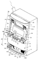
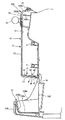
図1は、スロットマシン1の前面扉3が閉じた状態を示す斜視図、図2は、スロットマシン1の前面扉3が開いた状態を示す斜視図、図3は、スロットマシン1の筐体2を正面から示す図、図4は、スロットマシン1の正面下部を断面により示す図である。
1 is a perspective view showing a state in which the front door 3 of the
スロットマシン1は、図1及び図2に示すように、筐体2と前面扉3とからなる正面視略矩形状の本体(遊技機本体)4を有する。
As shown in FIGS. 1 and 2, the
前面扉3は、略平板状のフレーム20に、スタートレバー26やセレクタ9等の種々の装置類が装着されて構成されている。フレーム20は、フレーム20の上端部から高さ方向略中央部まで下方に移行するにしたがって手前側に突出するように傾斜した傾斜部20Aと、傾斜部20Aの下端から手前側に突出してフレーム20の左右に亘って所定の高さ幅で延在する突出部20Bと、突出部20Bよりも奥側に後退した位置で突出部20Bからフレーム20の下端部まで垂下する垂下部20Cを有する。
The front door 3 is configured by mounting various devices such as a
フレーム20は、左端部の上下複数カ所がヒンジ5(図2を参照)によって筐体2に連結されて取り付けられ、筐体2の前部を容易に開放及び閉塞できるようになっている。そして、フレーム20の右端部には、筐体2に対して前面扉3を閉塞して施錠状態とする施錠装置6と、その施錠装置6による施錠状態を解除して前面扉3を開放するためのキーシリンダ7が設けられている。
The
前面扉3の前面には、フレーム20に取り付けられた装置類によって、上方から下方に向かって順番に並ぶように、演出部3A、表示部3B、操作スイッチユニット3C、装飾部3D、払出部3Eが形成されている。
On the front surface of the front door 3, an effect unit 3 </ b> A, a display unit 3 </ b> B, an operation switch unit 3 </ b> C, a decoration unit 3 </ b> D, a payout unit 3 </ b> E are arranged in order from top to bottom by devices attached to the
演出部3Aは、遊技者に対して光や音、映像を用いて演出を行う演出装置21を有する。演出装置21は、フレーム20の傾斜部20Aに取り付けられており、遊技の進行に伴って点灯・点滅する上部ランプ21aと、上部ランプ21aの下方位置で左右両側に各々配置されて種々の効果音等を発生させる一対のスピーカ21b−1、21b−2と、これら一対のスピーカ21b−1、21b−2の間に配設されて、画像・映像等の種々の情報を表示する液晶ディスプレイ21cを有する。
The
表示部3Bは、遊技者に遊技状態を示す表示用パネル22を有する。表示用パネル22は、フレーム20の傾斜部20Aに開口する矩形の開口部に嵌合されて取り付けられている。表示用パネル22の略中央位置には、透明又は半透明な材質によって表示窓22aが一体成形されており、その表示窓22aから筐体2の内方の回転リール11a〜11cを視認できるようになっている。
The
操作スイッチユニット3Cは、表示用パネル22の下端から手前側に向かって平面状に突出する突出部20Bの上面部20Baに、ベットボタン23とメダル投入口24とが左右に離れて設けられている。そして、上面部20Baの手前側の端部で折曲されて垂下する突出部20Bの前面部20Bbに、精算ボタン25、回転リール11a〜11cの回転開始を指示するためのスタートレバー26、回転リール11a〜11cの回転停止を指示するためのストップボタン27等の各操作手段が横一列に並ぶように配設されている。なお、このベットボタン23は、前面扉3とは別体に構成され、前面扉3の表裏面を貫通する貫通穴部19に挿入装着され、スロットマシン1内部にあるベットボタン23の配線接続先である中継基板と接続線により接続されている。一方、ストップボタン27も同様に、前面扉3とは別体に構成され、前面扉3の表裏面を貫通する貫通穴部29に挿入装着され、スロットマシン1内部の上記中継基板と接続されている。
In the
更に、スタートレバー26には、前面扉3の内側に突出し、スタートレバー26に対する操作に応じて抽選にかかる信号を生成し中継基板に出力する図示しない遊技信号生成装置が設けられている。
Further, the
装飾部3Dは、機種名や遊技に関わるキャラクタ等を表示する装飾用パネル40を有する。装飾用パネル40は、装飾用パネル40の裏面側に設けられた照明装置の光源Pから照射される光によって照明されて、装飾が際立つようになっている。照明装置は、光源Pとして冷陰極管を備えており、図4に示すように、装飾用パネル40の表示部42とフレーム20の垂下部20Cとの間で前面扉3の左右に延在し、両端がフレーム20に支持されている。光源Pは、電源の供給を受けて放射状に光を照射する。
The
装飾用パネル40は、保護カバー51と減光手段61を備えている。保護カバー51は、フレーム20の垂下部20Cの前方で上下に延在する表示部52と、表示部52の下端で折曲されて後方に向かって延在し、メダル受け皿33に対向する対向部53とが一体に形成され、透明又は半透明のプラスチックやアクリル等、硬質の合成樹脂製材料等の光透過性部材によって構成されている。
The
減光手段61は、保護カバー51の対向部53の少なくとも一部を覆い、光源Pからメダル受け皿33に向かって照射される光を減光する構成を有しており、対向部53の上面に取り付けられて光源Pからメダル受け皿33に向かって照射される光を遮光する遮光プレート62と、遮光プレート62に開口して光源Pからメダル受け皿33に向かって照射される光を通過させる開口部66と、開口部66に脱着自在に取り付けられて開口部66を通過する光を透過させて光量や色等を変更する透過光調整部68によって構成されている。
The light reduction means 61 covers at least a part of the facing
開口部66は、光源Pから照射された光が通過してメダル受け皿33を照明する位置に設けられている。開口部66の大きさは、光源Pからメダル受け皿33内を照明するのに必要でかつ遊技者が眩しくない程度の光量の光を透過させることができる大きさに設定されている。
The
したがって、光源Pから照射された光を減光手段61で減光して、メダル受け皿33に照射される光の光量を調整することができ、適切な光量の光でメダル受け皿33を照明でき、遊技者にとって眩しすぎず、かつ、メダル受け皿33上のメダルの存否確認を容易ならしめ、メダル受け皿33上のメダルの取り忘れを防ぐことができる。
Therefore, the light emitted from the light source P can be attenuated by the dimming means 61 to adjust the amount of light emitted to the
特に、メダル受け皿33の底板部33Aの強度を補強するために底板部33Aの底面に金属製の板部材が敷設されて、上方からの光を反射し易い構造となっている場合には、減光手段61によって適切な光量に減光することにより、遊技者が眩しく感じるのを有効に防ぐことができる。
In particular, in order to reinforce the strength of the
そして、保護カバー51の表示部52と対向部43が一体に形成されているので、光を透過させるための開口部等を保護カバー51に開ける必要がない。したがって、針金等の棒状の異物が保護カバー51を貫通して挿入されるおそれがなく、スロットマシン1の設定状態を不正に変更する等の不正行為を有効に防ぐことができる。
And since the
払出部3Eは、メダル払出口31や演出用スピーカ32L、32R、メダル受け皿33等を有する。メダル払出口31は、図1に示すように、フレーム20の左右方向略中央位置に開口形成されており、排出用通路8(図2を参照)の下流端が連通して接続されている。演出用スピーカ32L、32Rは、メダル払出口31の左右方向両側に位置するように前面扉3のフレーム20に取り付けられている。
The
メダル受け皿33は、メダル受け皿取付板30を介してフレーム20に取り付けられている。メダル受け皿取付板30は、一枚の平板状の金属板によって構成されており、フレーム20の垂下部20Cに重ね合わせるように取り付けられて、前面扉3の左右に亘って延在し、左右の演出用スピーカ32L、32Rの前面を覆っている。
The
メダル受け皿取付板30の略中央には、フレーム20のメダル払出口31の位置に対応してメダル出口30aが開口形成されており、メダル払出口31からメダル受け皿33にメダルが排出されるようになっている。また、メダル受け皿取付板30の左右両側には、演出用スピーカ32L、32Rの位置に対応して複数の小孔30bがメッシュ状に形成されて、演出用スピーカ32L、32Rからの音声等が前面扉3の前方である手前側に向かって発せられるようになっている。
A medal outlet 30a is formed in the approximate center of the medal
メダル受け皿33は、フレーム20の垂下部20Cから手前側に突出して前面扉3の左右に延在するように取り付けられている。メダル受け皿33は、メダル払出口31よりも下方位置で底面が左右に広がる底板部33Aと、底板部33Aの外端縁に沿って設けられて底面から上方に延出する縦壁部33Bを有し、メダル受け皿取付板30に取り付けられた場合に、縦壁部33Bとメダル受け皿取付板30との間に囲まれて上方が開放された所定枚数のメダルを貯留可能な貯留空間を形成する構成を有する。
The
縦壁部33Bは、メダル受け皿取付板30から手前側に向かって延出するように基端がメダル受け皿取付板30に固定される左右一対の側面壁部33Ba、33Bbと、メダル受け皿取付板30に沿って左右に延在するように一対の側面壁部33Ba、33Bbの先端間を連結してメダル払出口31に対向配置される正面壁部33Bcを有する。
The
左側面壁部33Baは、前面扉3の左端部よりも内方に位置し、前面扉3の左端部と左側面壁部33Baとの間には灰皿33Cが配設されている。右側面壁部33Bbは、前面扉3の右端部に沿って位置し、メダル受け皿取付板30から手前側に向かって移行するにしたがって右側面壁部33Bbの上端が漸次下方に移行し、正面壁部33Bcの上端に滑らかに連続している。
The left side wall portion 33Ba is located inward of the left end portion of the front door 3, and an
筐体2は、スロットマシン1の骨格をなす部材であり、天板2A、底板2B、背板2C、左側板2D、右側板2Eからなり、図2に示すように、前部が開放された箱形状を有している。
The housing 2 is a member constituting the skeleton of the
筐体2の内方の略中央高さ位置には、リールユニット11が配設されている。リールユニット11は、複数個の回転リール11a〜11cを有している。各回転リール11a〜11cは、その回転中心軸線が筐体2の横幅方向に同一軸線上に延びるように配置されており、表示窓22aから回転リール11a〜11cの表面を視認できるようになっている。
A
回転リール11a〜11cの表面には、周回方向に所定間隔をおいて複数種類の図柄が表示されており、表示窓22aから上下に3つの図柄が視認できるように配置されている。そして、リール11a〜11cの正転により、各表示窓22aには各種図柄が上から下に移動しているように映し出される。
A plurality of types of symbols are displayed on the surfaces of the rotating reels 11a to 11c at predetermined intervals in the circumferential direction, and are arranged so that three symbols can be visually recognized from the top and bottom through the
各リール11a〜11cは、個々にステッピングモータ(図示せず)に連結されており、各ステッピングモータにより別個独立して回転駆動され、リール表面の図柄が表示窓22aから視認可能な位置に停止される。
Each of the reels 11a to 11c is individually connected to a stepping motor (not shown), and is driven to rotate independently by each of the stepping motors, and the symbols on the reel surface are stopped at a position where they can be seen from the
筐体2の内方の上部位置には、主制御基板ユニット12が配設されている。主制御基板ユニット12は、スロットマシン1の遊技動作を制御するメイン制御基板が制御基板収納ボックス内に収容された状態で、台座装置によって筐体2の背板2Cに取付支持されている。
A main
筐体2の内方の下部位置には、電源ボックス13とメダル払出手段14と補助タンク50が左右に並んで配置されている。電源ボックス13は、筐体2の左側板2Dに沿って設けられており、開閉扉13aを開くことで露出される正面部には、電源スイッチ、リセットスイッチ、設定キー挿入孔(いずれも図示せず)が設けられている。電源スイッチは、主制御装置等を始めとする各部に電源を供給するための起動スイッチである。
A
リセットスイッチは、スロットマシンの各種状態をリセットするためのスイッチである。本スロットマシン1は、各種データのバックアップ機能を有しており、万一停電が発生した際でも停電時の状態を保持し、停電からの復旧(復電)の際には停電時の状態に復帰できるようになっている。したがって、例えば遊技ホールの営業が終了する場合のように通常手順で電源を遮断すると遮断前の状態が記憶保持されるが、リセットスイッチを押しながら電源スイッチをオンすると、バックアップデータがリセットされるようになっている。また、電源スイッチがオンされている状態でリセットスイッチを押した場合には、エラー状態がリセットされる。
The reset switch is a switch for resetting various states of the slot machine. This
設定キー挿入孔は、ホール管理者などがメダルの出玉調整を行うためのものである。すなわち、ホール管理者等が設定キーを設定キー挿入孔へ挿入して操作することにより、スロットマシン1の設定状態(当選確率設定処理)を「設定1」から「設定6」まで変更できるようになっている。
The setting key insertion hole is for a hole manager or the like to adjust the appearance of medals. That is, the setting state (winning probability setting process) of the
メダル払出手段14は、図示していないスライド機構を介して筐体2の底板2Bの上面に取り付けられており、前面扉3を開放した状態で筐体2の内方から前方に向かって引き出すことができるようになっている。
The medal payout means 14 is attached to the upper surface of the
メダル払出手段14は、メダルを貯留するホッパ15と、ホッパ15内のメダルをメダル受け皿33に払い出す払出装置16と、ホッパ15から溢れたメダルをホッパ15の外に排出するメダル排出口18等を備えている。そして、底板2Bの上面に払出装置16がスライド移動可能に支持され、払出装置16の上部にホッパ15が取り付けられ、ホッパ15にメダル排出口18が形成されている。
The medal payout means 14 includes a
払出装置16は、モータ等の駆動手段により回転体を回転させて(いずれも図示せず)、ホッパ15内のメダルを払出口16aから払い出して排出用通路8に流入させる構成を有する。ホッパ15は、筐体2の上下方向に延在する平面視略矩形の胴部15Aと、胴部15Aの下端部を閉塞する底部15Bとからなる有底筒状をなす。胴部15Aは、左壁部15Acと右壁部15Adとが筐体2の左側板2D、右側板2Eと平行に延在し、後壁部15Abが筐体2の背板2Cに沿って延在し、前壁部15Aaが筐体2の前部で左右に延在するように配置される。
The
そして、胴部15Aの上端部は、上方に向かって開放されており、ホッパ15内にメダルが投入される投入口17が形成されている。底部15Bは、互いに対向して下方に移行するにしたがって漸次接近するように傾斜した左右一対の傾斜部15Ba、15Bbを有している。これら左右一対の傾斜部15Ba、15Bbのうち、図3で左側に示される傾斜部15Baには、払出装置16にメダルを供給する供給口が形成されている。
The upper end portion of the
そして、図3で右側に示される傾斜部15Bbは、払出装置16よりも筐体2の右側板2E側に突出し、底板2Bの上面と対向している。メダル排出口18は、補助タンク50の上方に位置し、ホッパ15から溢れてメダル排出口18から排出されたメダルを補助タンク50内に流入させることができるように、胴部15Aの右壁部15Adに形成されている。
In addition, the inclined portion 15Bb shown on the right side in FIG. 3 protrudes toward the
補助タンク50は、前面扉3を開放した状態で筐体2の内方から前方に向かって引き出して取り外しできるように、筐体2の底板2Bの上面に載せた状態で収容されて、遊技機本体4内に装着される。筐体2の底板2Bには、補助タンク50に収容したメダルを遊技機本体4の下方に位置する自動回収装置に供給するためのメダル回収穴が開口形成されている。
The
(第1の実施の形態)
以下、第1の形態について図面を参照にして詳細に説明する。
(First embodiment)
Hereinafter, the first embodiment will be described in detail with reference to the drawings.
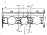
図5は、本実施の形態に係るスロットマシン1において、前面扉3の外側からのスロットマシン1内の装置に対する不正なアクセスを規制するための構成を説明する図である。図示のように、本実施の形態では、操作スイッチユニット3Cが前面扉3に対して着脱自在に取り付けられる構造であり、前面扉3の操作スイッチユニット3Cが取り付けられている部分には、操作スイッチユニット3Cのストップボタン27が装着されている貫通穴部29やベットボタン23が装着されている貫通穴部19と、スロットマシン1内部の主制御基板やホッパ基板等の遊技関連装置と、を仕切る遮断板80が設けられている。
FIG. 5 is a diagram illustrating a configuration for restricting unauthorized access to the devices in the
この遮断板80は、前面扉3の幅方向全域に亘って延在する長さで略矩形状に形成されており、スタートレバー26の接続線を通過させる接続線通過穴82と、ベットボタン23及びストップボタン27−1〜3等のスタートレバー26の接続線以外の操作部材の接続線を通過させる接続線通過穴84と、メダル投入口24から投入されたメダルを筐体2内にあるホッパに案内するメダル案内部86を有している。また、この遮断板80の両端の近傍位置にネジ止め部81が設けられている。
The blocking
接続線通過穴82は、スタートレバー26から筐体2内の配線接続先部材である中継基板に接続される接続線を挿通させることが可能となるように、極力小さく略矩形状に形成されている。同様に、接続線通過穴84も、操作スイッチユニット3Cが前面扉3に取り付けられた状態でストップボタン27−1〜3、及びベットボタン23から筐体2内の中継基板に接続する接続線を全て挿通可能である範囲で可及的に小さく形成されている。
The connection
メダル案内部86は、操作スイッチユニット3Cが前面扉3に取り付けられた状態でメダル投入口24の直下位置に位置してメダルを通過させるメダル通過口86aを有している。
The
一方、装飾パネル40は、操作スイッチユニット3Cのストップボタン27に対応する位置に設けられたストップボタン挿通穴91、スタートレバー26に対応する位置に設けられたスタートレバー挿通穴84、その上部両端位置に形成された係合片93を有している。
On the other hand, the
そして、この装飾パネル40は、ストップボタン挿通穴91、スタートレバー挿通穴84、及びキーシリンダ7を、それぞれ操作スイッチユニット3Cのストップボタン27、スタートレバー26、及びキーシリンダ受け穴87に対応させるとともに、操作スイッチユニット3Cの凸部受け穴89に装飾パネル40の裏面側に設けられた図示しない凸部を対応させ、係合片93を操作スイッチユニット3Cの端部スリット85に挿入して操作スイッチユニット3Cと一体化させた状態で前面扉3に固着される。これにより、操作スイッチユニット3Cが前面扉3から不正に取外されることが防止される。
In the
なお、本実施の形態では、上記操作スイッチユニット3Cと装飾パネル40を組み合わせた部材の前面扉3への取り付けを強固に行なうために、装飾パネル40の係合片93やその裏面側下部位置に形成された図示しない爪部を、前面扉3の所定箇所に形成された爪受け部に係合させている。
In the present embodiment, in order to firmly attach the member combining the
上記構成によれば、ベットボタン23やストップボタン27が取外されて貫通穴部19や29から針金等の工具が不正に挿入された場合であっても、前面扉3に設けられた遮断板80により、この工具の侵入を物理的に遮断することができる。
According to the above configuration, even when the
特に、本実施の形態では、遮断板80に設けられた接続線通過穴84を、ベットボタン23が装着されている貫通穴部19やストップボタン27が装着されている貫通穴部29よりも小さくすることが好ましい。これにより、貫通穴部19、29から不正に挿入された工具の可動範囲をより制限することができる。なお、接続線通過穴84を遮断板80ではなく、例えば、前面扉3の何れかの位置に設けても良い。この場合、接続線通過穴84からスロットマシン1内部への直線軌道上に不正対象となる主制御基板やホッパ基板が位置することがないように、前面扉3における接続線通過穴84を設ける場所を選定することが好ましい。
In particular, in the present embodiment, the connecting
また、例えば、主制御基板等の遊技の抽選の抽選結果を左右する重要な制御を行う遊技制御装置は、アクリル等の樹脂性のケースでカバーされた状態で筐体3内に設置されることがあるが、このような場合においても、わざわざ重要な装置全てを個々に樹脂製のケースに収容するという煩雑な作業を行うことなく、1個の遮断板80を設けるだけで不正対象となり得るスロットマシン1内の遊技関連装置を全て保護することができる。なお、さらに高い安全度を追求するために、重要な装置をアクリルケースに収容して筐体3内に設置した上でさらに遮断板80を設けても良い。
In addition, for example, a game control device that performs important control that affects the lottery result of a game such as a main control board is installed in the housing 3 in a state of being covered with a resin case such as acrylic. However, even in such a case, a slot that can be fraudulent only by providing one
一方、本実施の形態では、遊技の抽選に関連するスタートレバー26に対して、さらに不正行為に対する安全度を高める構成が具備されている。
On the other hand, in this embodiment, the
図6は、操作スイッチユニット3Cの構成を説明する図である。図示のように、本実施の形態では、スターレバー26及びそれに付属する遊技信号生成装置全体がカバー部材90によって覆われ、このスタートレバー26と略矩形状のカバー部材90により覆われた部分とによってスタートレバーユニット92が構成されている。
FIG. 6 is a diagram illustrating the configuration of the
このスタートレバーユニット92は、図6(a)及び図6(b)から理解されるように、操作スイッチユニット3Cに対して着脱自在となっている。なお、このスタートレバー92は、操作スイッチユニット3Cが前面扉3から取外された状態でないと、操作スイッチユニット3Cから取外せない構造である。
As can be understood from FIGS. 6A and 6B, the
図6(c)には、スタートレバーユニット92の内側の構造を概略的に示している。図示のように、スタートレバーユニット92のカバー部材90は、スタートレバーユニット92の基端部分に取り付けられる接続線を通すことが可能となるように、この基端部分に対向する位置に開口部90aが形成されている。そして、図6(d)に示すように、スタートレバーユニット92が操作スイッチユニット3Cに取り付けられた状態で、開口部90aに接続線95が挿通され、スタートレバーユニット92に接続される。なお、操作スイッチユニット3Cの底部における切欠き96は、操作スイッチユニット3Cを前面扉3に取り付ける際に、メダル案内装置86の位置に対応する部分である。
FIG. 6C schematically shows the inner structure of the
このようなスタートレバーユニット92が取り付けられた状態の操作スイッチユニット3Cが、前面扉3に固定されることによって、カバー部材90の開口部90aが遮断板80におけるスタートレバー用の接続線通過穴82(図5参照)の部分と当接する状態となり、接続線95は接続線通過穴82内に案内される。
The operation switch unit 3 </ b> C with the
上記構成によれば、一般的に不正対象になり易いスターレバー26の遊技信号生成装置が、カバー部材90と遮断板80により被覆された状態となるので、遊技の抽選に関連する重要な装置、すなわち、不正の対象となる可能性の高い装置を安全に保護することができる。また、万が一、不正を試みる者による工具の侵入などの衝撃によりスタートレバーユニット92が破損してしまった場合であっても、このスタートレバーユニット92は着脱自在に構成されているので、その交換を容易に行うことができる。
According to the above configuration, since the game signal generating device of the
(第2の実施の形態)
以下、第2の実施の形態について説明する。なお、第1の実施の形態と同様の要素には同一の符号を付し、その説明を省略する。
(Second Embodiment)
Hereinafter, a second embodiment will be described. The same elements as those in the first embodiment are denoted by the same reference numerals, and the description thereof is omitted.
図7は、本実施の形態に係るスロットマシン1の前面扉3の貫通穴部29に装着されたストップボタン27の被挿入部分をカバーするボタンカバー部材94の構成を説明する図である。図示のように、本実施の形態では、操作部3Cは第1の実施の形態のように着脱式のユニット型ではなく、前面扉3と一体型となっている。そして、各ストップボタン27−1、27−2、27−3の前面扉裏側の部分をまとめてカバーするボタンカバー部材94が設けられる。このボタンカバー部材94は、アクリルやポリカーボネート等の樹脂で形成されており、両側部に形成された取り付け部94aのネジ孔97において操作部3Cの所定箇所にネジ止めされることで、操作部3Cに固定される。
FIG. 7 is a view for explaining the configuration of the
また、ボタンカバー部材94におけるストップボタン27の高さ位置よりも高い位置には、各ストップボタン27−1、27−2、27−3の接続線95−1、95−2、95−3をそれぞれ通過させる3箇所のストップボタン用接続線通過穴96−1、96−2、96−3が等間隔に設けられている。
Further, the connection lines 95-1, 95-2, 95-3 of the stop buttons 27-1, 27-2, 27-3 are provided at positions higher than the height position of the stop button 27 in the
図8は、ボタンカバー部材94が取り付けられた状態の操作部3Cの構造を説明する図である。図示のように、前面扉3の各ストップボタン27−1〜27−3の部分がボタンカバー部材94により覆われた状態となることにより、不正を試みようとする者が、ストップボタン27を前面扉3の外側から取外して、その取外された部分の貫通穴部29(図1参照)から不正な工具を侵入させ、スロットマシン1内の遊技制御装置にアクセスしようとした場合であっても、ボタンカバー部材94がその工具を遮り、スロットマシン1内部の装置への不正なアクセスを禁止することができる。
FIG. 8 is a diagram illustrating the structure of the
特に、本実施の形態では、上述のようにボタンカバー部材94のストップボタン用接続線通過穴96がストップボタン27の高さ位置よりも高い位置に設けられているので、不正を行う者が貫通穴部29から工具を侵入させ、それをストップボタン用接続線通過穴96に通しても、その工具をスロットマシン1内部におけるストップボタン27の高さ位置よりも低い位置に設けられたホッパ基板等の遊技制御装置へアクセスさせることが極めて困難なものとなる。従って、不正行為に対する安全度をより向上させることができる。
In particular, in the present embodiment, since the stop button connecting
なお、ストップボタン27の接続線通過穴96を下部位置、すなわち、ストップボタン27の高さ位置よりも低い位置に設け、スロットマシン1内部におけるストップボタン27の高さ位置よりも高い位置に設けられた主制御基板等の遊技制御装置への不正なアクセスを防止するようにしても良い。
The connecting
(第3の実施の形態)
以下、第3の実施の形態について説明する。なお、上記第2の実施の形態と同様の要素には、同一の符号を付し、その説明を省略する。
(Third embodiment)
Hereinafter, a third embodiment will be described. The same elements as those in the second embodiment are denoted by the same reference numerals, and the description thereof is omitted.
図9は、本実施の形態に係るスロットマシン1のストップボタン27の前面扉裏側の部分に設けられたボタンカバー部材94の構成を説明する図である。図示のように、本実施の形態では、ボタンカバー部材94の下部位置でストップボタン27の高さ位置によりも低い位置に接続線案内部98が接続線通過穴96に連通するようにして設けられている。この接続線案内部98は、ボタンカバー部材94から下方に屈曲して所定長さ延在する湾曲形状を有しており、その先端が開口されて接続線出口100が形成されている。従って、ストップボタン27に設けられる接続線95は、接続線案内部98に案内され接続線出口100から出て、図示しない中継基板に接続される。
FIG. 9 is a view for explaining the configuration of the
上記構成によれば、ストップボタン27が装着されている部分の貫通穴部29(図1参照)と接続線出口100を直線で結ぶことができない形状であるので、この貫通穴部29から不正に工具が挿通された場合であってもスロットマシン1内部への侵入経路(すなわち、接続線案内部98の内部)が非直線状となり、遊技制御装置へのアクセスが困難なものとなる。従って、スロットマシン1内の装置に対する不正な操作をより効果的に防止することができる。特に、上述のように、接続線案内部98が下方に湾曲した形状であることから、不正を行う者が、工具を貫通穴部29に挿通して接続線案内部98を経由して接続線出口100から出すことに成功したとしても、この工具は下方向に誘導された状態となるので、スロットマシン1内の比較的上部位置に配置されている主制御基板へのアクセスは極めて困難なものとなる。従って、不正行為に対する安全度をより向上させることができる。
According to the above configuration, the through hole portion 29 (see FIG. 1) where the stop button 27 is attached cannot be connected to the
(第4の実施の形態)
以下、第4の実施の形態について説明する。なお、第3の実施の形態と同様の要素には、同一の符号を付し、その説明を省略する。
(Fourth embodiment)
Hereinafter, a fourth embodiment will be described. The same elements as those in the third embodiment are denoted by the same reference numerals, and the description thereof is omitted.
図10は、本実施の形態におけるボタンカバー部材94を前面扉3の裏側から取り付ける状態を説明する説明図であり、図示のように、本実施の形態におけるボタンカバー部材94の下部位置の接続線通過穴96に連通するようにして屈曲形状に形成されストップボタン27の接続線95をまとめてカバーし案内する接続線カバー部102が設けられている。この接続線カバー部102は、ボタンカバー部材94がストップボタン27の前面扉裏側の部分に取り付けられた状態で、接続線95の接続先である中継基板130の中継基板コネクタ132に到達可能な長さに形成されており、さらに、その状態で中継基板コネクタ132に対向する位置に、接続線出口100が設けられている。これにより、接続線カバー部102にカバーされている接続線95は、この接続線出口100から出て、そのコネクタ106が中継基板コネクタ132に接続される。
FIG. 10 is an explanatory diagram for explaining a state in which the
図11は、ボタンカバー部材94を前面扉3の裏側から取り付けた状態を概略的に示す図である。図示のように、本実施の形態の接続線カバー部102により、ストップボタン27の前面扉裏側の部分、及び接続線95は、ボタンカバー部材94とその接続線カバー部102により全体的に覆われた状態となる。
FIG. 11 is a diagram schematically showing a state in which the
これにより、ストップボタン27が前面扉3の外側から取外された場合でも、ストップボタン27が装着されていた部分の貫通穴部29と連通するスロットマシン1内部の空間は、ホッパ基板や主制御基板から物理的に断絶されることとなる。従って、ストップボタン27が取外された部分の貫通穴部29から不正に工具が挿入された場合であっても、この工具のホッパ基板や主制御基板等の遊技制御装置へのアクセスをほぼ確実に防止することができる。
Thereby, even when the stop button 27 is removed from the outside of the front door 3, the space inside the
(第5の実施の形態)
以下、第5の実施の形態について説明する。なお、第1の実施の形態と同様の要素には、同一の符号を付し、その説明を省略する。
(Fifth embodiment)
The fifth embodiment will be described below. The same elements as those in the first embodiment are denoted by the same reference numerals, and the description thereof is omitted.
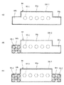
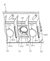
図12は、本実施の形態にかかるスロットマシン1において各ストップボタン27−1〜27−3の接続線95を、上述の中継基板に取り付ける部分であるコネクタ側から接続線通過穴84に通過させる構成を説明する図であり、図13は、図12における要部の概略拡大図である。
FIG. 12 shows that the
図示のように、本実施の形態では、接続線通過穴84は、主開口部84aと、この主開口部84aの両端部にそれぞれ形成された突出開口部84b及び84cによって構成された正面視逆T字形状に形成されている。また、ストップボタン27−1〜3の接続線95−1〜95−3においては、それぞれ中継基板に接続させるコネクタ106−1〜106−3が設けられており、このコネクタ106−1〜106−3の断面の形状及び面積は、接続線通過穴84の主開口部84aの断面の形状及び面積とほぼ一致している。そして、本実施の形態においては、配線95−1、95−2におけるコネクタ106−1、106−2の近傍位置には、引き出し防止部材104−1、及び104−2がそれぞれ設けられている。
As shown in the figure, in the present embodiment, the connection
引き出し防止部材104−1の断面の形状及び面積は、接続線通過穴84全体の断面の形状及び面積とほぼ一致している。すなわち、引き出し防止部材104−1は、接続線通過穴84を通過可能となるように可及的に大きな面積に形成されている。また、引き出し防止部材104−2は、引き出し防止部材104−1と比較して、接続線通過穴84の突出開口部84bに対応する箇所が欠けている形状に形成されている。
The shape and area of the cross section of the drawer preventing member 104-1 are substantially the same as the shape and area of the cross section of the entire connection
図14(a)〜図14(c)は、接続線95−1〜95−3をコネクタ106−1〜106−3側から接続線通過穴84に挿通させる態様を説明する説明図である。
FIG. 14A to FIG. 14C are explanatory diagrams for explaining a mode in which the connection lines 95-1 to 95-3 are inserted from the connectors 106-1 to 106-3 into the connection
先ず、図14(a)に示すように、接続線95−1をコネクタ106−1側から接続線通過穴84に挿通させ、引き出し防止部材104−1を通過させる。上述のように引き出し防止部材104−1の断面の形状及び面積が接続線通過穴84の形状及び面積とほぼ一致することから、引き出し防止部材104−1は、接続線通過穴84のほぼ全体を通って通過する。
First, as shown to Fig.14 (a), the connection line 95-1 is penetrated to the connection
そして、接続線95−1の引き出し防止部材104−1を接続線通過穴84に通過させた後に、図14(b)に示すように、穴84を通過した状態の接続線95−1を突出開口部84bの部分にまとめて、接続線95−2をコネクタ106−2側から接続線通過穴84に挿通させ、引き出し防止部材104−2を通過させる。上述のように、引き出し防止部材104−2は、引き出し防止部材104−1と比較して、接続線通過穴84の突出開口部84bに対応する箇所が欠けている形状に形成されているので、突出開口部84bに接続線95−1が挿通されている状態であっても、主開口部84aと突出開口部84bの部分で引き出し防止部材104−2をぎりぎり通過させることができる。
And after letting the lead- out prevention member 104-1 of the connection line 95-1 pass through the connection
更に、接続線95−2の引き出し防止部材104−2を接続線通過穴84に通過させた後に、図14(c)に示すように、穴84を通過した状態の接続線95−2を突出開口部84cの部分にまとめて、接続線95−3をコネクタ106−3側から接続線通過穴84に通過させる。上述のように、コネクタ106−3の断面の形状及び面積は、接続線通過穴84の主開口部84aの断面の形状及び面積とほぼ一致することから、コネクタ106−3は、接続線通過穴84のほぼ全体を通って通過する。
Further, after the pull-out preventing member 104-2 of the connection line 95-2 is passed through the connection
そして、接続線通過穴部84を通って筐体2の内部側に入ったコネクタ106−1〜106−3は、筐体2内の中継基板に接続される。なお、図示しないが、ベットボタン23の接続線は、このコネクタ106−3を接続線通過穴84に通過させた後に、この接続線通過穴84に通過させることができる。
Then, the connectors 106-1 to 106-3 that have entered the inside of the housing 2 through the connection
上記構成によれば、ただ1つの可及的に面積の小さい接続線通過穴84においてコネクタ106を有する接続線95を通過させることができる。従って、ベットボタン23等の操作部材が外部から取外され、そのベットボタン23が装着されていた部分の貫通穴部19などから接続線通過穴84を狙って不正な工具の挿入が試みられた場合であっても、その接続線通過穴84を通してスロットマシン1内部へ工具を侵入させることが極めて困難なもとなる。
According to the above configuration, the
一方、上述のように接続線通過穴部84に挿通されている接続線95−1〜95−3は、例えば、初めに、左ストップボタン27−1に対応する接続線95−1を前面扉3側に引っ張り抜こうとしても、接続線通過穴84をぎりぎり通過可能な大きさの引き出し防止部材104−1が他の中ストップボタン27−2の接続線95−2などに引っ掛かり抜く事が出来ない。すなわち、接続線通過穴部84から接続線95を前面扉3側に引き抜く際には、挿入する場合とは逆に、先ず、右ストップボタン27−3の接続線95−3を引きコネクタ106−3を接続線通過穴84から抜き出し、次に、中ストップボタン27−2の接続線95−2を引き、コネクタ106−2及び引き出し防止部材104−2を接続線通過穴84から抜き出し、最後に、左ストップボタン27−1の接続線95−3を引き、コネクタ106−3及び引き出し防止部材104−1を接続線通過穴84から抜き出す必要がある。
On the other hand, as described above, the connection lines 95-1 to 95-3 inserted through the connection line
従って、前面扉3の外側からのストップボタン27の不正な抜き出しが困難なものとなるので、スロットマシン1内部の装置への不正な操作の原因となるストップボタン27の取外しそのものを防止することができる。
Accordingly, since it is difficult to illegally extract the stop button 27 from the outside of the front door 3, it is possible to prevent the removal of the stop button 27 that causes an illegal operation to the device inside the
(第6の実施の形態)
以下、第6の実施の形態について図面を参照にして詳細に説明する。本実施の形態における特徴的な構成は、ストップボタン27の貫通穴部29への装着構造である。
(Sixth embodiment)
Hereinafter, a sixth embodiment will be described in detail with reference to the drawings. A characteristic configuration in the present embodiment is a mounting structure of the stop button 27 in the through
図15は、操作スイッチユニット3Cにストップボタン27を装着する状態を示す図である。なお、図には、中ストップボタン27−2の装着状態のみを示しているが、左ストップボタン27−1や右ストップボタン27−3の装着の場合も同様である。図示のように、本実施の形態では、中ストップボタン27−2は、操作スイッチユニット3Cの裏側(すなわち、前面扉3の裏側)から貫通穴部29に挿入装着される。
FIG. 15 is a diagram illustrating a state in which the stop button 27 is attached to the
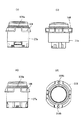
図16は、本実施の形態のストップボタン27の構造を説明する説明図であり、図16(a)は、ストップボタン27の正面図、図16(b)は、ストップボタン27の側面図、図16(c)は、ストップボタン27の背面図、図16(d)は、ストップボタン27の平面図を示している。図示のように、ストップボタン27は、その側面27a上の対向位置に該側面27aの形状に沿って延在するように突出形成されたフランジ部108を有している。
FIG. 16 is an explanatory diagram for explaining the structure of the stop button 27 of the present embodiment, in which FIG. 16 (a) is a front view of the stop button 27, FIG. 16 (b) is a side view of the stop button 27, FIG. 16C is a rear view of the stop button 27, and FIG. 16D is a plan view of the stop button 27. As shown in the figure, the stop button 27 has a
また、ストップボタン27の側面27aの対向配置されたそれぞれのフランジ部108の隣接位置には、後述する操作スイッチユニット3Cの係止突起115(図15参照)に係止させるための係止片107が設けられている。この係止片107は、その基端部分107aが平行配置され上下方向に延在する一対のフレーム状に形成されておりストップボタン27の側面27aに固着されている。そして、そのフレーム状部分の先端部分には、側面27aから離間する方向に延在する叉状の突起挟み部107bが形成されている。なお、本実施の形態において、フランジ部108は、側面27aに沿って下方に向かって漸次傾斜する傾斜形状を有している。
Further, a
そして、図15に示しているように、各ストップボタン27−1〜27−3は、隔壁部111により仕切られており、この各隔壁部111の側面には、係合部109−1〜109−3が設けられている。この係合部109−1〜109−3には、フランジ部108の差し込みを許容する図示しない差込部分が形成されている。
As shown in FIG. 15, the stop buttons 27-1 to 27-3 are partitioned by
更に、操作スイッチユニット3Cのボタン取り付け面113における貫通穴部29の縁部近傍位置には、ストップボタン27の係止片107を係止させる上述の係止突起115が、貫通穴部29を挟む対向位置に形成されている。
Further, the above-described locking projection 115 that locks the
図17〜図19は、ストップボタン27−2を操作スイッチユニット3Cの貫通穴部29−2に取り付ける態様を説明する図である。先ず、図17に示すように、ストップボタン27−2を操作スイッチユニット3Cの内側から貫通穴部29−2に挿入する。本実施の形態において、ストップボタン27−2の貫通穴部29−2への挿入は、それぞれのフランジ部108を各係止突起115−2に対応させる、すなわち、各フランジ部108の位置が係合部109−2の位置とずれるようにして行なわれる。
FIGS. 17-19 is a figure explaining the aspect which attaches the stop button 27-2 to the through-hole part 29-2 of 3 C of operation switch units. First, as shown in FIG. 17, the stop button 27-2 is inserted into the through hole 29-2 from the inside of the
次に、図18、及び図19に示すように、貫通穴部29−2に挿入したストップボタン27−2を回転させる。このようにストップボタン27−2を回転させることで、各フランジ部108が係合部109−2の上記差込部分に差し込まれて係合されるとともに、係合片107が弾性変形してその突起挟み部107bが係止突起115に引っかかり係止される。
Next, as shown in FIGS. 18 and 19, the stop button 27-2 inserted into the through hole 29-2 is rotated. By rotating the stop button 27-2 in this way, each
これにより、ストップボタン27が、操作スイッチユニット3Cの裏面側、すなわち、貫通穴部29を通過不能なストップボタン27を前面扉3の裏面側から取り付け固定されているので、前面扉3の外側から工具などにストップボタン27が抉られて取外されてしまうことを防止することができる。すなわち、スロットマシン1の内部へ不正なアクセスの可能性を与える、ストップボタン27が取外されることによる貫通穴部29の露出を効果的に防止することができる。
Thereby, since the stop button 27 is attached and fixed from the back side of the
(第7の実施の形態)
以下、第7の実施の形態について図面を参照にして詳細に説明する。なお、第6の実施の形態と同様の要素には、同一の符号を付し、その説明を省略する。
(Seventh embodiment)
Hereinafter, a seventh embodiment will be described in detail with reference to the drawings. In addition, the same code | symbol is attached | subjected to the element similar to 6th Embodiment, and the description is abbreviate | omitted.
図20は、操作スイッチユニット3Cにストップボタン27を装着する状態を示す図である。図示のように、本実施の形態では、各隔離壁111の貫通穴部29側に対向する一対のガイド部材118−1〜118−3が設けられている。このガイド部材118の両端部には、ストップボタン27を貫通穴部29に装着した状態で固定するための一対のスライド片120が、スライド可能に係止される。なお、図には、中ストップボタン27−2の部分に対応するガイド部材118−2に係止されたスライド片120のみを図示しているが、勿論、他のストップボタン27−1、27−3の部分に対応するガイド部材118−1、118−3にもスライド片120を係止させることが可能である。
FIG. 20 is a diagram illustrating a state in which the stop button 27 is attached to the
図21は、本実施の形態のストップボタン27の構造を説明する説明図であり、図21(a)は、ストップボタン27の正面図、図21(b)は、ストップボタン27の側面図、図21(c)は、ストップボタン27の背面図、図21(d)は、ストップボタン27の平面図を示している。図示のように、本実施の形態におけるフランジ部108は、ストップボタン27の側面27aに沿って略水平に形成されており、ストップボタン27の正面及び背面から視てほぼ中央位置に上方に突出する突出部108aを備えている。この突出部108aには、ストップボタン27の本体部分を挟んだ対向位置に係止突起115を係合させるための孔部108bが形成されている。
FIG. 21 is an explanatory view for explaining the structure of the stop button 27 of the present embodiment. FIG. 21 (a) is a front view of the stop button 27, FIG. 21 (b) is a side view of the stop button 27, FIG. 21C is a rear view of the stop button 27, and FIG. 21D is a plan view of the stop button 27. As shown in the figure, the
図22は、ストップボタン27−2が貫通穴部29−2に取り付けた状態を示す図である。図から理解されるように、ストップボタン27−2の取り付けは、ストップボタン27−2をフランジ部108の孔部108bと係止突起115が対応する位置で操作スイッチユニット3Cの裏側から貫通穴部29−2に挿入し、一対のスライド部材120を相互にストップボタン27−2側にスライドさせることで、フランジ部108をスライド部材120とボタン取り付け面113との間の空間に差し込むことで行なう。すなわち、フランジ部108が、スライド部材120とボタン取り付け面113との間で係止されることでストップボタン27−2が操作スイッチユニット3Cに固定された状態となる。なお、スライド部材120をストップボタン27−2から離間する方向にスライドさせることで、フランジ部108に対する係止状態が解除される。
FIG. 22 is a diagram illustrating a state in which the stop button 27-2 is attached to the through hole 29-2. As can be understood from the drawing, the stop button 27-2 is attached to the stop button 27-2 from the back side of the
上記構成によれば、前面扉3の外側からのストップボタン27の取外しを防止しつつ、ストップボタン27の操作スイッチユニット3C裏側からの着脱を容易に行なうことができる。
According to the above configuration, it is possible to easily attach and detach the stop button 27 from the back side of the
なお、本発明は、上記実施の形態に限定されるものではなく、発明の要旨の範囲内で種々変更が可能である。例えば、本実施の形態では、前面扉3の貫通穴部に挿入装着される装着部材として、ベットボタン23やストップボタン27について挙げているが、これに限られるものではなく、他の種々の部材を適用可能である。
In addition, this invention is not limited to the said embodiment, A various change is possible within the range of the summary of invention. For example, in the present embodiment, the
また、本発明に係る遊技機としては、上記実施の形態において説明した種類のスロットマシンに限られるものではなく、パチンコ機、遊技球を用いて遊技を行うスロットマシン、雀球、アレンジボール等の他の種々の遊技機が含まれる。 In addition, the gaming machine according to the present invention is not limited to the type of slot machine described in the above embodiment, but includes a pachinko machine, a slot machine for playing a game using a game ball, a sparrow ball, an arrangement ball, and the like. Various other gaming machines are included.
1 スロットマシン(遊技機)
2 筐体
3 前面扉
4 遊技機本体
19 貫通穴部
23 ベットボタン
27 ストップボタン
29 貫通穴部
80 遮断板(侵入規制手段)
84 接続線通過穴部
94 ボタンカバー部材(侵入規制手段)
98 接続線案内部
102 接続線カバー部材
1 slot machine (game machine)
2 Housing 3 Front door 4 Gaming machine
84 Connecting
98
Claims (4)
前記装着部材は、遊技機内部の配線接続先部材に接続させる複数のコネクタが先端に設けられて、前記各コネクタから延びる接続線を有する操作部材として構成され、
前記前面扉には、前記接続線の通過を許容する接続線通過穴部を有するとともに、前記操作部材が装着されている前記貫通穴部と前記遊技関連装置との間を仕切る仕切り部材が設けられ、
前記各接続線には、それぞれ引き出し防止部材が設けられ、
一の接続線に設けられた前記引き出し防止部材は、前記接続線通過穴部とその断面形状及び面積が略同一であり、
他の接続線に設けられた前記引き出し防止部材は、前記接続線通過穴部において前記一の接続線の接続線が通過している領域以外の領域とその断面形状及び面積が略同一であることを特徴とする遊技機。 A housing having an opening on the front side, a front door that is attached to the opening of the housing so as to be openable and closable and has a through-hole portion, and an attachment that is inserted into the through-hole portion from the outside of the front door In a gaming machine comprising a member and a game-related device having a function related to a game provided inside the gaming machine,
The mounting member is configured as an operation member having a plurality of connectors to be connected to a wiring connection destination member inside the gaming machine at a tip, and having connection lines extending from the connectors,
The front door includes a connection line passage hole that allows the connection line to pass therethrough, and a partition member that partitions the game hole-related device and the through hole in which the operation member is mounted. ,
Each connection line is provided with a pull-out prevention member,
The pull-out prevention member provided in one connection line has substantially the same cross-sectional shape and area as the connection line passage hole portion,
The pull-out prevention member provided on the other connection line has substantially the same cross-sectional shape and area as a region other than the region where the connection line of the one connection line passes in the connection line passage hole portion. A gaming machine characterized by
板状の遮断板として構成されたことを特徴とする請求項1又は2に記載の遊技機。 The partition member is
The gaming machine according to claim 1 , wherein the gaming machine is configured as a plate-shaped blocking plate.
前記仕切り部材は、前記スタートレバーユニットの接続線を通過させる接続線通過穴部を残して、前記スタートレバーユニットを覆うスタートレバーユニットカバー部材として形成されたことを特徴とする請求項1に記載の遊技機。 The game-related device includes a start lever that protrudes from the front door, and is formed integrally with the start lever and protrudes to the inside of the front door, and generates a lottery signal in response to an operation on the start lever. A game signal generator and a start lever unit,
The partition member, leaving a connection wire passing hole for passing the connecting line of the start lever unit according to claim 1, characterized in that said formed as a start lever unit cover member covering the start lever unit Gaming machine.
Priority Applications (1)
| Application Number | Priority Date | Filing Date | Title |
|---|---|---|---|
| JP2009060691A JP5531425B2 (en) | 2009-03-13 | 2009-03-13 | Game machine |
Applications Claiming Priority (1)
| Application Number | Priority Date | Filing Date | Title |
|---|---|---|---|
| JP2009060691A JP5531425B2 (en) | 2009-03-13 | 2009-03-13 | Game machine |
Publications (3)
| Publication Number | Publication Date |
|---|---|
| JP2010213752A JP2010213752A (en) | 2010-09-30 |
| JP2010213752A5 JP2010213752A5 (en) | 2012-04-26 |
| JP5531425B2 true JP5531425B2 (en) | 2014-06-25 |
Family
ID=42973257
Family Applications (1)
| Application Number | Title | Priority Date | Filing Date |
|---|---|---|---|
| JP2009060691A Expired - Fee Related JP5531425B2 (en) | 2009-03-13 | 2009-03-13 | Game machine |
Country Status (1)
| Country | Link |
|---|---|
| JP (1) | JP5531425B2 (en) |
Families Citing this family (13)
| Publication number | Priority date | Publication date | Assignee | Title |
|---|---|---|---|---|
| JP5903787B2 (en) * | 2011-07-19 | 2016-04-13 | 株式会社三洋物産 | Game machine |
| JP5942353B2 (en) * | 2011-07-19 | 2016-06-29 | 株式会社三洋物産 | Game machine |
| JP5903786B2 (en) * | 2011-07-19 | 2016-04-13 | 株式会社三洋物産 | Game machine |
| JP2013252225A (en) * | 2012-06-06 | 2013-12-19 | Sammy Corp | Slot machine |
| JP5826163B2 (en) * | 2012-12-28 | 2015-12-02 | 京楽産業.株式会社 | Game machine |
| JP5610175B1 (en) * | 2014-01-10 | 2014-10-22 | 山佐株式会社 | Assembling structure of stop button for revolving game machine, revolving game machine and stop button unit for revolving game machine |
| JP6310810B2 (en) * | 2014-08-07 | 2018-04-11 | 株式会社ニューギン | Game machine |
| JP6556069B2 (en) * | 2016-02-22 | 2019-08-07 | 株式会社三洋物産 | Game machine |
| JP6061046B2 (en) * | 2016-03-11 | 2017-01-18 | 株式会社三洋物産 | Game machine |
| JP6061045B2 (en) * | 2016-03-11 | 2017-01-18 | 株式会社三洋物産 | Game machine |
| JP2017047319A (en) * | 2016-12-14 | 2017-03-09 | 株式会社三洋物産 | Game machine |
| JP2018089432A (en) * | 2018-03-02 | 2018-06-14 | 株式会社三洋物産 | Game machine |
| JP7140390B2 (en) * | 2019-07-25 | 2022-09-21 | 株式会社藤商事 | game machine |
Family Cites Families (9)
| Publication number | Priority date | Publication date | Assignee | Title |
|---|---|---|---|---|
| JP4087077B2 (en) * | 2001-04-19 | 2008-05-14 | サミー株式会社 | Device for preventing cable disconnection in gaming machines |
| JP2004081328A (en) * | 2002-08-23 | 2004-03-18 | Aruze Corp | Game machine |
| JP2006180999A (en) * | 2004-12-27 | 2006-07-13 | Heiwa Corp | Control unit attaching device for game machine |
| JP4828214B2 (en) * | 2005-11-29 | 2011-11-30 | 株式会社平和 | Game machine |
| JP4684178B2 (en) * | 2006-06-22 | 2011-05-18 | 株式会社ソフイア | Game machine |
| JP4771904B2 (en) * | 2006-09-22 | 2011-09-14 | 株式会社オリンピア | Game machine |
| JP3993225B1 (en) * | 2007-04-18 | 2007-10-17 | ネット株式会社 | Integrated operation unit and rotating game machine |
| JP4897597B2 (en) * | 2007-07-13 | 2012-03-14 | サミー株式会社 | Game machine |
| JP5093723B2 (en) * | 2007-10-23 | 2012-12-12 | 株式会社北電子 | Game machine and movable claw cover |
-
2009
- 2009-03-13 JP JP2009060691A patent/JP5531425B2/en not_active Expired - Fee Related
Also Published As
| Publication number | Publication date |
|---|---|
| JP2010213752A (en) | 2010-09-30 |
Similar Documents
| Publication | Publication Date | Title |
|---|---|---|
| JP5531425B2 (en) | Game machine | |
| JP5897506B2 (en) | Game machine | |
| JP5897507B2 (en) | Game machine | |
| JP6294442B2 (en) | Game machine | |
| JP6126717B2 (en) | Game machine | |
| JP6338712B2 (en) | Game machine | |
| JP5146988B2 (en) | Game machine | |
| JP6165222B2 (en) | Game machine | |
| JP5146987B2 (en) | Game machine | |
| JP5938014B2 (en) | Game machine | |
| JP5897505B2 (en) | Game machine | |
| JP6038365B2 (en) | Game machine | |
| JP5946432B2 (en) | Game machine | |
| JP6473195B2 (en) | Game machine | |
| JP6499715B2 (en) | Game machine | |
| JP6152196B2 (en) | Game machine | |
| JP6695643B2 (en) | Amusement machine | |
| JP6393710B2 (en) | Game machine | |
| JP6276807B2 (en) | Game machine | |
| JP6225232B2 (en) | Game machine | |
| JP6294433B2 (en) | Game machine | |
| JP6151388B2 (en) | Game machine | |
| JP5946433B2 (en) | Game machine | |
| JP5946431B2 (en) | Game machine | |
| JP6511404B2 (en) | Gaming machine |
Legal Events
| Date | Code | Title | Description |
|---|---|---|---|
| A521 | Request for written amendment filed |
Free format text: JAPANESE INTERMEDIATE CODE: A523 Effective date: 20120309 |
|
| A621 | Written request for application examination |
Free format text: JAPANESE INTERMEDIATE CODE: A621 Effective date: 20120309 |
|
| A977 | Report on retrieval |
Free format text: JAPANESE INTERMEDIATE CODE: A971007 Effective date: 20130529 |
|
| A131 | Notification of reasons for refusal |
Free format text: JAPANESE INTERMEDIATE CODE: A131 Effective date: 20130604 |
|
| A521 | Request for written amendment filed |
Free format text: JAPANESE INTERMEDIATE CODE: A523 Effective date: 20130805 |
|
| TRDD | Decision of grant or rejection written | ||
| A01 | Written decision to grant a patent or to grant a registration (utility model) |
Free format text: JAPANESE INTERMEDIATE CODE: A01 Effective date: 20140325 |
|
| A61 | First payment of annual fees (during grant procedure) |
Free format text: JAPANESE INTERMEDIATE CODE: A61 Effective date: 20140407 |
|
| R150 | Certificate of patent or registration of utility model |
Ref document number: 5531425 Country of ref document: JP Free format text: JAPANESE INTERMEDIATE CODE: R150 |
|
| R250 | Receipt of annual fees |
Free format text: JAPANESE INTERMEDIATE CODE: R250 |
|
| R250 | Receipt of annual fees |
Free format text: JAPANESE INTERMEDIATE CODE: R250 |
|
| R250 | Receipt of annual fees |
Free format text: JAPANESE INTERMEDIATE CODE: R250 |
|
| R250 | Receipt of annual fees |
Free format text: JAPANESE INTERMEDIATE CODE: R250 |
|
| R250 | Receipt of annual fees |
Free format text: JAPANESE INTERMEDIATE CODE: R250 |
|
| R250 | Receipt of annual fees |
Free format text: JAPANESE INTERMEDIATE CODE: R250 |
|
| LAPS | Cancellation because of no payment of annual fees |