JP5530282B2 - Ventilation air conditioning system and building - Google Patents
Ventilation air conditioning system and building Download PDFInfo
- Publication number
- JP5530282B2 JP5530282B2 JP2010161317A JP2010161317A JP5530282B2 JP 5530282 B2 JP5530282 B2 JP 5530282B2 JP 2010161317 A JP2010161317 A JP 2010161317A JP 2010161317 A JP2010161317 A JP 2010161317A JP 5530282 B2 JP5530282 B2 JP 5530282B2
- Authority
- JP
- Japan
- Prior art keywords
- air
- space
- ventilation
- floor
- conditioning
- Prior art date
- Legal status (The legal status is an assumption and is not a legal conclusion. Google has not performed a legal analysis and makes no representation as to the accuracy of the status listed.)
- Active
Links
- 238000009423 ventilation Methods 0.000 title claims description 257
- 238000004378 air conditioning Methods 0.000 title claims description 216
- 238000007664 blowing Methods 0.000 claims description 117
- 230000001143 conditioned effect Effects 0.000 claims description 19
- 230000002265 prevention Effects 0.000 claims description 8
- 239000011810 insulating material Substances 0.000 claims description 6
- 238000010438 heat treatment Methods 0.000 description 14
- 238000011144 upstream manufacturing Methods 0.000 description 8
- 230000000694 effects Effects 0.000 description 5
- 238000012423 maintenance Methods 0.000 description 4
- 238000005192 partition Methods 0.000 description 4
- 238000010276 construction Methods 0.000 description 3
- 238000001816 cooling Methods 0.000 description 3
- 238000009413 insulation Methods 0.000 description 2
- 239000000463 material Substances 0.000 description 2
- 238000013022 venting Methods 0.000 description 2
- 238000004887 air purification Methods 0.000 description 1
- 238000004140 cleaning Methods 0.000 description 1
- 239000011491 glass wool Substances 0.000 description 1
- 239000002184 metal Substances 0.000 description 1
Images


Description
本発明は、建物の換気空調システム及びこの換気空調システムを備えた建物に関するものである。 The present invention relates to a ventilation air conditioning system for buildings and a building equipped with the ventilation air conditioning system.
従来から、建物の床上空間における換気と空調とを同時に行える換気空調システムが知られている(例えば、特許文献1等を参照)。 Conventionally, a ventilation air-conditioning system capable of simultaneously performing ventilation and air conditioning in a building floor space is known (see, for example, Patent Document 1).
しかしながら、特許文献1のような従来の換気空調システムでは、換気装置と空調装置とから多くのダクトが床上空間に向けて配設される複雑な構造とされており、施工作業やメンテナンス作業の煩雑さがあった。
However, the conventional ventilation air-conditioning system such as
そこで、本発明は、ダクトが少ない簡易な構造で、施工作業やメンテナンス作業を容易に行うことができる換気空調システム及びこの換気空調システムを備えた建物を提供することを目的としている。 Therefore, an object of the present invention is to provide a ventilation air-conditioning system capable of easily performing construction work and maintenance work with a simple structure having few ducts, and a building including the ventilation air-conditioning system.
前記目的を達成するために、本発明の換気空調システムは、第1空間と第2空間とを有する床上空間を備えた建物に換気装置と空調装置とが設置されており、前記建物の前記床上空間の前記第1空間と前記第2空間とに面して第1空間用給気口と第2空間用給気口とがそれぞれ設けられており、前記換気装置及び前記空調装置と前記第1空間用給気口及び前記第2空間用給気口との間は、共通の換気空調分岐ユニットを介して、第1空間用ダクトと第2空間用ダクトとによりそれぞれ接続されており、前記換気空調分岐ユニット内は、前記換気装置の第1空間用換気空気吹出部と前記空調装置の第1空間用空調空気吹出部と前記第1空間用ダクトとが連通する第1空間用分岐流路と、前記換気装置の第2空間用換気空気吹出部と前記空調装置の第2空間用空調空気吹出部と前記第2空間用ダクトとが連通する第2空間用分岐流路とに区画されていることを特徴とする。 In order to achieve the above object, a ventilation air-conditioning system according to the present invention includes a ventilation device and an air-conditioning device installed in a building having a floor space having a first space and a second space. A first space air supply port and a second space air supply port are respectively provided facing the first space and the second space, and the ventilation device, the air conditioner, and the first space are provided. The space air inlet and the second space air inlet are connected to each other by a first space duct and a second space duct via a common ventilation air conditioning branching unit, respectively. The air conditioning branching unit includes a first space branch air passage that communicates the first space ventilation air blowing portion of the ventilation device, the first space air conditioning air blowing portion of the air conditioning device, and the first space duct. , Ventilation air outlet for second space of said ventilator and said air conditioner Said second space for conditioned air blowout portion second space duct is characterized in that it is divided into a second space for the branch channel communicating.
ここで、前記換気装置と前記空調装置とは、一体化された換気空調装置とされているとよい。 Here, the ventilation device and the air conditioning device may be an integrated ventilation air conditioning device.
また、前記換気空調装置は、ヒートポンプ式のエアコンディショナの屋内機であり、屋外に設置された屋外機と接続されているとよい。 The ventilation air conditioner is an indoor unit of a heat pump type air conditioner, and may be connected to an outdoor unit installed outdoors.
さらに、前記空調装置における前記第1空間用空調空気吹出部と前記第2空間用空調空気吹出部とには、逆流防止弁が設けられているとよい。 Furthermore, a backflow prevention valve may be provided in the first space-conditioned air blowing portion and the second space-conditioned air blowing portion in the air conditioner.
また、前記換気装置と前記空調装置とは、前記建物の床下空間に設置されているとよい。 Moreover, the said ventilation apparatus and the said air conditioner are good to be installed in the underfloor space of the said building.
また、前記空調装置は、床下用吹出部を備えているとよい。 Moreover, the said air conditioner is good to provide the blowing part for underfloor.
さらに、前記床下空間は、前記建物の床と基礎底盤コンクリートと基礎側壁コンクリートとに囲まれているとともに、前記基礎側壁コンクリートには基礎断熱材が取り付けられているとよい。 Further, the underfloor space may be surrounded by the floor of the building, the foundation bottom concrete, and the foundation side wall concrete, and a foundation heat insulating material may be attached to the foundation side wall concrete.
本発明の建物は、上記した換気空調システムを備えていることを特徴とする。 The building of the present invention includes the above-described ventilation air conditioning system.
このような本発明の換気空調システムは、第1空間と第2空間とを有する床上空間を備えた建物に換気装置と空調装置とが設置されている。 In such a ventilation air conditioning system of the present invention, a ventilation device and an air conditioning device are installed in a building having a floor space having a first space and a second space.
そして、建物の床上空間の第1空間と第2空間とに面して第1空間用給気口と第2空間用給気口とがそれぞれ設けられており、換気装置及び空調装置と第1空間用給気口及び第2空間用給気口との間は、共通の換気空調分岐ユニットを介して、第1空間用ダクトと第2空間用ダクトとによりそれぞれ接続されている。 A first space air supply port and a second space air supply port are respectively provided facing the first space and the second space of the floor space of the building, and the ventilation device, the air conditioning device, and the first space are provided. The space air supply port and the second space air supply port are connected to each other by a first space duct and a second space duct through a common ventilation air conditioning branching unit.
そのうえで、換気空調分岐ユニット内は、換気装置の第1空間用換気空気吹出部と空調装置の第1空間用空調空気吹出部と第1空間用ダクトとが連通する第1空間用分岐流路と、換気装置の第2空間用換気空気吹出部と空調装置の第2空間用空調空気吹出部と第2空間用ダクトとが連通する第2空間用分岐流路とに区画された構成とされている。 In addition, the ventilation air-conditioning branch unit includes a first space branch flow path in which the first space ventilation air blowing portion of the ventilation device, the first space air-conditioning air blowing portion of the air conditioning device, and the first space duct communicate with each other. The second space ventilation air blowing portion of the ventilator, the second space air conditioning air blowing portion of the air conditioner, and the second space branch passage communicating with the second space duct are configured. Yes.
こうした構成なので、換気空調分岐ユニットの存在によりダクトの分岐部が簡略化されるため、ダクトが少ない簡易な構造となり、施工作業やメンテナンス作業を容易に行うことができる。 With such a configuration, the branching portion of the duct is simplified due to the presence of the ventilation / air conditioning branching unit, so that a simple structure with few ducts can be achieved, and construction work and maintenance work can be easily performed.
ここで、換気装置と空調装置とが、一体化された換気空調装置とされている場合は、換気装置と空調装置とが別体となっているのに比べ、余計なスペースを必要としないうえに、換気装置と空調装置と換気空調分岐ユニットとの組み立てを容易に行うことができる。 Here, when the ventilator and the air conditioner are integrated, the extra space is not required compared to the case where the ventilator and the air conditioner are separate. Furthermore, the ventilation device, the air conditioning device, and the ventilation air conditioning branching unit can be easily assembled.
また、換気空調装置が、ヒートポンプ式のエアコンディショナの屋内機であり、屋外に設置された屋外機と接続されている場合は、ヒートポンプを用いるため、省エネルギー性能に優れたものとすることができる。 In addition, when the ventilation air conditioner is an indoor unit of a heat pump type air conditioner and is connected to an outdoor unit installed outdoors, the heat pump is used, so that the energy saving performance can be improved. .
さらに、空調装置における第1空間用空調空気吹出部と第2空間用空調空気吹出部とには、逆流防止弁が設けられている場合は、空調運転は行っておらず、換気運転のみをおこなっているときに、換気用の空気が第1空間用空調空気吹出部や第2空間用空調空気吹出部に流れ込んで換気機能が低下するのを防止することができる。 Furthermore, when the backflow prevention valve is provided in the 1st space conditioned air blowing part and the 2nd space conditioned air blowing part in the air conditioner, the air conditioning operation is not performed and only the ventilation operation is performed. In this case, it is possible to prevent the ventilation function from being deteriorated due to the ventilation air flowing into the first space conditioned air blowing section or the second space conditioned air blowing section.
また、換気装置と空調装置とは、建物の床下空間に設置されている場合は、床上空間が、これらに占用されず、有効に利用することができ、意匠的外観も良い。 Further, when the ventilation device and the air conditioner are installed in the under-floor space of the building, the over-floor space is not occupied and can be used effectively, and the design appearance is good.
また、空調装置が、床下用吹出部を備えている場合は、床下用吹出部から暖気を吹き出し、床下空間内で対流させて、床上空間を均一にムラなく暖める床下暖房を行うことができる。 In addition, when the air conditioner includes an underfloor blowing section, warm air is blown out from the underfloor blowing section, and convection is performed in the underfloor space, so that the underfloor heating can be performed to uniformly warm the overfloor space.
さらに、床下空間は、建物の床と基礎底盤コンクリートと基礎側壁コンクリートとに囲まれているとともに、基礎側壁コンクリートには基礎断熱材が取り付けられている場合は、床下空間を断熱構造とするため、床下空間内の空気の熱を屋外に極力漏らすことなく、特に、エネルギー効率のよい床下暖房を行うことができる。 In addition, the underfloor space is surrounded by the floor of the building, the foundation floor concrete, and the foundation side wall concrete, and when the foundation side wall concrete is attached to the foundation side wall concrete, the underfloor space has a heat insulating structure. In particular, energy-efficient underfloor heating can be performed without leaking the heat of the air in the underfloor space to the outside as much as possible.
このような本発明の建物は、本発明の換気空調システムを備えた構成とされている。 Such a building of the present invention is configured to include the ventilation air conditioning system of the present invention.
こうした構成なので、上記した本発明の換気空調システムの効果を奏する建物とすることができる。 Since it is such a structure, it can be set as the building which show | plays the effect of the ventilation air conditioning system of this invention mentioned above.
以下、本発明を実施するための形態を、図面に示す実施例に基づいて説明する。 DESCRIPTION OF EMBODIMENTS Hereinafter, modes for carrying out the present invention will be described based on examples shown in the drawings.
先ず、実施例の構成について説明する。 First, the configuration of the embodiment will be described.
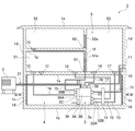
図1は、実施例の換気空調システムを備えた建物1の概略構成を示している。
FIG. 1 shows a schematic configuration of a
まず、このような建物1は、基礎断熱として構築された基礎底盤コンクリート1bと、その側縁に立設された基礎側壁コンクリート1cと、さらにその上に立設された外壁部1dと、その外壁部1dの上端開口を塞ぐ天井部1eとから主に構成されている。
First, such a
そして、この天井部1eと外壁部1dとに囲まれる空間は、1階部分の床としての床部1aによって床下空間4と床上空間5とに区切られている。
The space surrounded by the
さらに、床上空間5は、中間壁1fと2階部分の床としての床部1gとが設けられており、第1空間としての1階居室空間51と、第2空間としての2階居室空間52と、共有空間としての階段スペース53とに区画され、2階建ての建物とされている。
Furthermore, the
なお、建物1内の空間配置が分かり易いように、階段スペース53における階段の図示は省略した。
In addition, illustration of the staircase in the
ここで、共有空間としての階段スペース53と1階居室空間51との間の中間壁1fには、出入口としてのドア51aが設けられており、このドア51aの下側と床部1aとの間には、第1空間換気空調用排気口としての隙間61が設けられている。
Here, an
また、共有空間としての階段スペース53と2階居室空間52との間の中間壁1fには、出入口としてのドア52aが設けられており、このドア52aの下側と床部1gとの間には、第2空間換気空調用排気口としての隙間62が設けられている。
Further, a
さらに、基礎側壁コンクリート1cの床下空間4側には、基礎断熱材18が貼り付けられており、床下空間4内の空気の熱が屋外に極力漏れない断熱構造となっている。
Furthermore, the foundation
なお、この基礎断熱材18としては、グラスウールなどが好適に用いられる。
As the basic
そして、この実施例の換気空調システムでは、床下空間4に換気空調装置としてのエアコンディショナの屋内機3が設置されている。 In the ventilation air conditioning system of this embodiment, an indoor unit 3 of an air conditioner as a ventilation air conditioner is installed in the underfloor space 4.
この換気空調装置としてのエアコンディショナの屋内機3は、換気装置3Aと空調装置3Bとが一体化されたものであり、換気機能、冷暖房機能、及び除湿機能を有している。
The indoor unit 3 of the air conditioner as the ventilation air conditioner is an integrated unit of the
ここで、この換気空調装置としてのエアコンディショナの屋内機3は、ヒートポンプ式であり、建物1の屋外に設置された屋外機2と接続されている。
Here, the indoor unit 3 of the air conditioner as the ventilation air conditioner is a heat pump type, and is connected to the
また、エアコンディショナの屋内機3の内部には、屋外機2に繋がっている熱媒循環管路21が接続されている。
In addition, a heat
さらに、このエアコンディショナの屋内機3は、図2に示したように、その内部が、換気装置3A内の換気排気用空間30a及び換気給気用空間30bと、空調装置3B内の空調用空間30cとに区画されている。
Further, as shown in FIG. 2, the indoor unit 3 of the air conditioner includes an
ここで、エアコンディショナの屋内機3における換気排気用空間30aと、換気給気用空間30bとは、空気の流れが逆方向とされ、上流側と下流側とが逆になっている。
Here, in the
また、換気給気用空間30bと、空調用空間30cとは、空気の流れが順方向とされ、上流側と下流側とが同一になっている。
Further, the ventilation /
そして、エアコンディショナの屋内機3における換気排気用空間30aでは、その上流側に、換気用吸込部37を備え、その下流側には、内気吹出部38を備えているとともに、これらの間に、強制吹出手段としてのファン8が設けられている。
And in the
また、エアコンディショナの屋内機3における換気給気用空間30bでは、その上流側に、外気吸込部31を備え、その下流側には、強制吹出手段としてのファン8がそれぞれ設けられた第1空間用換気空気吹出部としての1階用換気空気吹出部33Aと、第2空間用換気空気吹出部としての2階用換気空気吹出部33Bとを備えている。
Further, in the ventilation /
ここで、換気排気用空間30aと換気給気用空間30bとの間は、熱交換素子から成る仕切り材9で仕切られている。
Here, the ventilation /
なお、この熱交換素子から成る仕切り材9としては、換気排気用空間30a内の汚れた空気が換気給気用空間30b内へ流入して清浄化された空気が汚染されないように、熱伝導性の高い金属板などの非通気性のものが好適に用いられる。
The partition member 9 made of this heat exchange element has thermal conductivity so that the dirty air in the ventilation /
さらに、エアコンディショナの屋内機3における空調用空間30cでは、その上流側に、空調空気吸込部32Aと、床下空調空気吸込部32Bとを備え、その下流側には、強制吹出手段としてのファン8がそれぞれ設けられた第1空間用空調空気吹出部としての1階用空調空気吹出部35と、第2空間用空調空気吹出部としての2階用空調空気吹出部36と、床下用吹出部34とを備えている。
Further, the
ここで、1階用空調空気吹出部35には、逆流防止弁35aが設けられている。
Here, a
また、2階用空調空気吹出部36にも、逆流防止弁36aが設けられている。
The second-floor air-
さらに、エアコンディショナの屋内機3における空調用空間30c内には、熱交換器3bが設けられており、上流側の空間と下流側の空間とに仕切られている。
Further, a
なお、図示は省略したが、この熱交換器3bに屋外機2からの熱媒循環管路21が接続されている。
In addition, although illustration was abbreviate | omitted, the heat-
そして、エアコンディショナの屋内機3の換気給気用空間30bと空調用空間30cとの下流側には、換気空調分岐ユニット3Cが設けられている。
And the ventilation air-
この換気空調分岐ユニット3Cは、第1空間用分岐流路としての1階用分岐流路39aと第2空間用分岐流路としての2階用分岐流路39bとに区画されている。
The ventilation / air
ここで、1階用分岐流路39aの上流側には、第1空間用空気吹出部としての1階用空気吹出部39Aを備えており、この1階用空気吹出部39Aは、下流側の1階用換気空気吹出部33A及び1階用空調空気吹出部35と連通されている。
Here, on the upstream side of the first-
また、2階用分岐流路39bの上流側には、第2空間用空気吹出部としての2階用空気吹出部39Bを備えており、この2階用空気吹出部39Bは、下流側の2階用換気空気吹出部33B及び2階用空調空気吹出部36と連通されている。
Further, on the upstream side of the second-
一方で、建物1において、図1に示したように、外壁部1dには、外気吸入口10と、内気吐出口11とが設けられている。
On the other hand, in the
さらに、建物1における第1空間としての1階居室空間51の床部1aには、グリル付きの第1空間用給気口としての1階用給気口12と、床下空間4と連通するグリル付きの別の給気口13と、グリル付きの床下空調用排気口14とが設けられている。
Further, the
また、建物1における第2空間としての2階居室空間52の床部1gには、グリル付きの第2空間用給気口としての2階用給気口15が設けられている。
The
さらに、建物1における共有空間としての階段スペース53の床部1aには、グリル付きの換気用排気口16と、グリル付きの空調用排気口17とが設けられている。
Further, the
そして、換気空調装置としてのエアコンディショナの屋内機3の外気吸込部31と外気吸入口10との間は、ダクト71を介して接続されている。
And the outside
また、床下空調空気吸込部32Bと床下空調用排気口14との間は、ダクト72を介して接続されている。
The underfloor air-conditioning air suction part 32 </ b> B and the underfloor air-
さらに、空調空気吸込部32Aと空調用排気口17との間は、ダクト73を介して接続されている。
Furthermore, the conditioned air suction part 32 </ b> A and the air
そのうえで、ダクト71,72,73の中継部に、空気清浄化手段としてのフィルターボックス19が設けられている。
In addition, a
なお、フィルターボックス19内には、図2に示したように、換気空気と空調空気とが混合するのを防止する隔壁19aが設けられている。
In addition, as shown in FIG. 2, the
そして、換気空調分岐ユニット3Cの1階用空気吹出部39Aと1階用給気口12との間は、第1空間用ダクトとしてのダクト74を介して接続されている。
The first-
また、換気空調分岐ユニット3Cの2階用空気吹出部39Bと2階用給気口15との間は、第2空間用ダクトとしてのダクト75を介して接続されている。
Further, the second
なお、このダクト75の下側部分は、他のダクトと同様、床下空間4に配設されているが、上側部分は、中間壁1f内と2階部分の床としての床部1g内とに配設されている。
The lower part of the
そして、換気空調装置としてのエアコンディショナの屋内機3の換気用吸込部37と換気用排気口16との間は、ダクト76を介して接続されている。
The
また、内気吹出部38と内気吐出口11との間は、ダクト77を介して接続されている。
Further, the
そして、換気空調装置としてのエアコンディショナの屋内機3には、図1に示したように、このエアコンディショナの屋内機3を制御する制御部3aが内蔵されている。
As shown in FIG. 1, the indoor unit 3 of the air conditioner as the ventilation air conditioner incorporates a
さらに、床上空間5には、この実施例の換気空調システムを所望の運転パターンに設定するための図示省略のコントローラが設けられている。
Further, the
そして、このコントローラから制御部3aへ設定信号が送信され、換気空調装置としてのエアコンディショナの屋内機3が、その設定信号に基づいて制御される。
And a setting signal is transmitted from this controller to the
次に、実施例の換気空調システムの運転パターンについて説明する。 Next, the operation pattern of the ventilation air conditioning system of an Example is demonstrated.
なお、図3〜図6では、換気用の空気の流れを黒矢印で示し、空調用の空気の流れは白抜矢印で示し、床下空調用の空気の熱の伝わりは点線矢印で示して説明する。 3 to 6, the flow of air for ventilation is indicated by black arrows, the flow of air for air conditioning is indicated by white arrows, and the heat transfer of air for underfloor air conditioning is indicated by dotted arrows. To do.
まず、換気運転時のパターンについて説明する。 First, the pattern at the time of ventilation operation is demonstrated.
建物1の床上空間5内の換気運転は、現在では、連続的であるか間欠的であるかにかかわらず、必ず行わなくてはならないものである。
At present, the ventilation operation in the
この換気運転時は、制御部3aは、換気空調装置としてのエアコンディショナの屋内機3の外気吸込部31から換気用の空気を吸い込み、1階用換気空気吹出部33A及び2階用換気空気吹出部33Bから換気用の空気を吹き出し、換気用吸込部37から排気された換気用の空気を吸い込み、それを内気吹出部38から吹き出す制御を行う。
During this ventilation operation, the
このように制御を行うと、図3に示したように、外気吸入口10から吸入された換気用の空気(外気)は、ダクト71を通って、中継部のフィルターボックス19により清浄化され、エアコンディショナの屋内機3の外気吸込部31から吸い込まれる。
When the control is performed as described above, as shown in FIG. 3, the ventilation air (outside air) sucked from the
ここで、1階用換気空気吹出部33Aから吹き出された換気用の空気は、換気空調分岐ユニット3Cの1階用分岐流路39aを介して、1階用空気吹出部39Aからダクト74を通って、1階用給気口12から1階居室空間51へ給気される。
Here, the ventilation air blown out from the first floor ventilation
そして、1階居室空間51内を換気した後、第1空間換気空調用排気口としてのドア51aの隙間61から共有空間としての階段スペース53へ排気され、階段スペース53も換気した後、換気用排気口16からダクト76を通って、換気用吸込部37から吸い込まれてから内気吹出部38から吹き出され、ダクト77を通って、内気吐出口11から建物1の屋外へ排気される。
Then, after the inside of the first
また、2階用換気空気吹出部33Bから吹き出された換気用の空気は、換気空調分岐ユニット3Cの2階用分岐流路39bを介して、2階用空気吹出部39Bからダクト75を通って、2階用給気口15から2階居室空間52へ給気される。
The ventilation air blown out from the second-floor ventilation
そして、2階居室空間52内を換気した後、第2空間換気空調用排気口としてのドア52aの隙間62から共有空間としての階段スペース53へ排気され、階段スペース53も換気した後、1階居室空間51を換気した換気用の空気とともに、換気用排気口16からダクト76を通って、換気用吸込部37から吸い込まれてから内気吹出部38から吹き出され、ダクト77を通って、内気吐出口11から建物1の屋外へ排気される。
Then, after ventilating the interior of the second-
すなわち、この循環を繰り返す。 That is, this circulation is repeated.
次に、暖房を行う際の換気空調運転時のパターンについて説明する。 Next, the pattern at the time of ventilation air conditioning operation at the time of heating is demonstrated.
まず、床上空間5を、即効性を有する暖房のみで暖めたいときは、制御部3aは、換気空調装置としてのエアコンディショナの屋内機3の外気吸込部31から換気用の空気を吸い込み、1階用換気空気吹出部33A及び2階用換気空気吹出部33Bから換気用の空気を吹き出し、換気用吸込部37から排気された換気用の空気を吸い込み、それを内気吹出部38から吹き出すとともに、空調空気吸込部32Aから空調用の空気を吸い込み、1階用空調空気吹出部35及び2階用空調空気吹出部36から空調用の空気(暖気)を吹き出す制御を行う。
First, when it is desired to warm the
このように制御を行うと、図4に示したように、外気吸入口10から吸入された換気用の空気(外気)は、ダクト71を通って、中継部のフィルターボックス19により清浄化され、エアコンディショナの屋内機3の外気吸込部31から吸い込まれるとともに、空調用排気口17から吸い込まれた空調用の空気は、ダクト73を通って、中継部のフィルターボックス19により清浄化され、エアコンディショナの屋内機3の空調空気吸込部32Aから吸い込まれる。
When the control is performed in this way, as shown in FIG. 4, the ventilation air (outside air) sucked from the
ここで、1階用換気空気吹出部33Aから吹き出された換気用の空気及び1階用空調空気吹出部35から吹き出された空調用の空気(暖気)は、換気空調分岐ユニット3Cの1階用分岐流路39aを介して、1階用空気吹出部39Aからダクト74を通って、1階用給気口12から1階居室空間51へ給気される。
Here, the ventilation air blown from the first floor ventilation
そして、1階居室空間51内を換気空調した後、第1空間換気空調用排気口としてのドア51aの隙間61から共有空間としての階段スペース53へ排気され、階段スペース53も換気空調した後、換気用の空気相当分の空気は、換気用排気口16からダクト76を通って、換気用吸込部37から吸い込まれてから内気吹出部38から吹き出され、ダクト77を通って、内気吐出口11から建物1の屋外へ排気されるとともに、空調用の空気相当分の空気は、空調用排気口17からダクト73内へ排気される。
After the first
また、2階用換気空気吹出部33Bから吹き出された換気用の空気及び2階用空調空気吹出部36から吹き出された空調用の空気(暖気)は、換気空調分岐ユニット3Cの2階用分岐流路39bを介して、2階用空気吹出部39Bからダクト75を通って、2階用給気口15から2階居室空間52へ給気される。
The ventilation air blown from the second-floor ventilation
そして、2階居室空間52内を換気空調した後、第2空間換気空調用排気口としてのドア52aの隙間62から共有空間としての階段スペース53へ排気され、1階居室空間51を換気空調した後の換気用の空気及び空調用の空気とともに階段スペース53も換気空調した後、換気用の空気相当分の空気は、1階居室空間51の換気用の空気相当分の空気とともに、換気用排気口16からダクト76を通って、換気用吸込部37から吸い込まれてから内気吹出部38から吹き出され、ダクト77を通って、内気吐出口11から建物1の屋外へ排気されるとともに、空調用の空気相当分の空気は、1階居室空間51の空調用の空気相当分の空気とともに、空調用排気口17からダクト73内へ排気される。
After the second-
すなわち、この循環を繰り返す。 That is, this circulation is repeated.
次に、床上空間5を、床下暖房のみで暖めたいときは、制御部3aは、換気空調装置としてのエアコンディショナの屋内機3の外気吸込部31から換気用の空気を吸い込み、1階用換気空気吹出部33A及び2階用換気空気吹出部33Bから換気用の空気を吹き出し、換気用吸込部37から排気された換気用の空気を吸い込み、それを内気吹出部38から吹き出すとともに、床下空調空気吸込部32Bから床下空調用の空気を吸い込み、床下用吹出部34から床下空調用の空気(暖気)を吹き出す制御を行う。
Next, when it is desired to warm the
このように制御を行うと、図5に示したように、外気吸入口10から吸入された換気用の空気(外気)は、ダクト71を通って、中継部のフィルターボックス19により清浄化され、エアコンディショナの屋内機3の外気吸込部31から吸い込まれるとともに、床下空調用排気口14から吸い込まれた床下空調用の空気は、ダクト72を通って、中継部のフィルターボックス19により清浄化され、エアコンディショナの屋内機3の床下空調空気吸込部32Bから吸い込まれる。
When the control is performed in this way, as shown in FIG. 5, the ventilation air (outside air) sucked from the
ここで、1階用換気空気吹出部33Aから吹き出された換気用の空気は、換気空調分岐ユニット3Cの1階用分岐流路39aを介して、1階用空気吹出部39Aからダクト74を通って、1階用給気口12から1階居室空間51へ給気される。
Here, the ventilation air blown out from the first floor ventilation
また、床下用吹出部34から吹き出された床下空調用の空気(暖気)は、主に床下空間4内を対流し、その熱は、床部1aを介して床上空間5へ伝達され、床上空間5を均一にムラなく暖めるとともに、吹き出しにより床下空間4を溢れた床下空調用の空気が、別の給気口13から1階居室空間51へ給気される。
Also, the air for underfloor air conditioning (warm air) blown out from the
そして、1階居室空間51内を空調した後、床下用吹出部34から吹き出された床下空調用の空気相当分の空気は、床下空調用排気口14からダクト72へ排気され、残りの換気用の空気相当分の空気は、第1空間換気空調用排気口としてのドア51aの隙間61から共有空間としての階段スペース53へ排気され、階段スペース53も換気した後、換気用排気口16からダクト76を通って、換気用吸込部37から吸い込まれてから内気吹出部38から吹き出され、ダクト77を通って、内気吐出口11から建物1の屋外へ排気される。
Then, after air-conditioning the first-
さらに、2階用換気空気吹出部33Bから吹き出された換気用の空気は、換気空調分岐ユニット3Cの2階用分岐流路39bを介して、2階用空気吹出部39Bからダクト75を通って、2階用給気口15から2階居室空間52へ給気される。
Further, the ventilation air blown out from the second-floor ventilation
そして、2階居室空間52内を換気した後、第2空間換気空調用排気口としてのドア52aの隙間62から共有空間としての階段スペース53へ排気され、1階居室空間51を換気した後の床下空調用の空気相当分の空気を除いた換気用の空気とともに階段スペース53も換気した後、1階居室空間51の換気用の空気相当分の空気とともに、換気用排気口16からダクト76を通って、換気用吸込部37から吸い込まれてから内気吹出部38から吹き出され、ダクト77を通って、内気吐出口11から建物1の屋外へ排気される。
Then, after the inside of the second-
すなわち、この循環を繰り返す。 That is, this circulation is repeated.
次に、床上空間5を、即効性を有する暖房と床下暖房との両方で暖めたいときは、制御部3aは、換気空調装置としてのエアコンディショナの屋内機3の外気吸込部31から換気用の空気を吸い込み、1階用換気空気吹出部33A及び2階用換気空気吹出部33Bから換気用の空気を吹き出し、換気用吸込部37から排気された換気用の空気を吸い込み、それを内気吹出部38から吹き出すとともに、空調空気吸込部32A及び床下空調空気吸込部32Bから空調用の空気を吸い込み、1階用空調空気吹出部35、2階用空調空気吹出部36、及び床下用吹出部34から空調用の空気(暖気)及び床下空調用の空気(暖気)を吹き出す制御を行う。
Next, when the
このように制御を行うと、図6に示したように、外気吸入口10から吸入された換気用の空気(外気)は、ダクト71を通って、中継部のフィルターボックス19により清浄化され、エアコンディショナの屋内機3の外気吸込部31から吸い込まれるとともに、空調用排気口17から吸い込まれた空調用の空気は、ダクト73を通って、中継部のフィルターボックス19により清浄化され、エアコンディショナの屋内機3の空調空気吸込部32Aから吸い込まれ、床下空調用排気口14から吸い込まれた床下空調用の空気は、ダクト72を通って、中継部のフィルターボックス19により清浄化され、エアコンディショナの屋内機3の床下空調空気吸込部32Bから吸い込まれる。
When the control is performed in this way, as shown in FIG. 6, the ventilation air (outside air) sucked from the
ここで、1階用換気空気吹出部33Aから吹き出された換気用の空気及び1階用空調空気吹出部35から吹き出された空調用の空気(暖気)は、換気空調分岐ユニット3Cの1階用分岐流路39aを介して、1階用空気吹出部39Aからダクト74を通って、1階用給気口12から1階居室空間51へ給気される。
Here, the ventilation air blown from the first floor ventilation
また、床下用吹出部34から吹き出された床下空調用の空気(暖気)は、主に床下空間4内を対流し、その熱は、床部1aを介して床上空間5へ伝達され、床上空間5を均一にムラなく暖めるとともに、吹き出しにより床下空間4を溢れた床下空調用の空気が、別の給気口13から1階居室空間51へ給気される。
Also, the air for underfloor air conditioning (warm air) blown out from the
そして、1階居室空間51内を換気空調した後、床下用吹出部34から吹き出された床下空調用の空気相当分の空気は、床下空調用排気口14からダクト72へ排気され、残りの換気用の空気及び空調用の空気相当分の空気は、第1空間換気空調用排気口としてのドア51aの隙間61から共有空間としての階段スペース53へ排気され、階段スペース53も換気した後、換気用排気口16からダクト76を通って、換気用吸込部37から吸い込まれてから内気吹出部38から吹き出され、ダクト77を通って、内気吐出口11から建物1の屋外へ排気されるとともに、空調用の空気相当分の空気は、空調用排気口17からダクト73内へ排気される。
Then, after the inside of the first-
さらに、2階用換気空気吹出部33Bから吹き出された換気用の空気及び2階用空調空気吹出部36から吹き出された空調用の空気(暖気)は、換気空調分岐ユニット3Cの2階用分岐流路39bを介して、2階用空気吹出部39Bからダクト75を通って、2階用給気口15から2階居室空間52へ給気される。
Further, the ventilation air blown from the second-floor ventilation
そして、2階居室空間52内を換気空調した後、第2空間換気空調用排気口としてのドア52aの隙間62から共有空間としての階段スペース53へ排気され、1階居室空間51を換気空調した後の換気用の空気及び空調用の空気相当分の空気とともに階段スペース53も換気空調した後、換気用の空気相当分の空気は、1階居室空間51の換気用の空気相当分の空気とともに、換気用排気口16からダクト76を通って、換気用吸込部37から吸い込まれてから内気吹出部38から吹き出され、ダクト77を通って、内気吐出口11から建物1の屋外へ排気されるとともに、空調用の空気相当分の空気は、1階居室空間51の空調用の空気相当分の空気とともに、空調用排気口17からダクト73内へ排気される。
After the second-
すなわち、この循環を繰り返す。 That is, this circulation is repeated.
次に、冷房を行う際の換気空調運転時のパターンについて説明する。 Next, the pattern at the time of ventilation air conditioning operation at the time of cooling will be described.
床上空間5を、冷房で冷やしたいときは、制御部3aは、換気空調装置としてのエアコンディショナの屋内機3の外気吸込部31から換気用の空気を吸い込み、1階用換気空気吹出部33A及び2階用換気空気吹出部33Bから換気用の空気を吹き出し、換気用吸込部37から排気された換気用の空気を吸い込み、それを内気吹出部38から吹き出すとともに、空調空気吸込部32Aから空調用の空気を吸い込み、1階用空調空気吹出部35及び2階用空調空気吹出部36から空調用の空気(冷気)を吹き出す制御を行う。
When it is desired to cool the
このように制御を行うと、図4に示したように、外気吸入口10から吸入された換気用の空気(外気)は、ダクト71を通って、中継部のフィルターボックス19により清浄化され、エアコンディショナの屋内機3の外気吸込部31から吸い込まれるとともに、空調用排気口17から吸い込まれた空調用の空気は、ダクト73を通って、中継部のフィルターボックス19により清浄化され、エアコンディショナの屋内機3の空調空気吸込部32Aから吸い込まれる。
When the control is performed in this way, as shown in FIG. 4, the ventilation air (outside air) sucked from the
ここで、1階用換気空気吹出部33Aから吹き出された換気用の空気及び1階用空調空気吹出部35から吹き出された空調用の空気(冷気)は、換気空調分岐ユニット3Cの1階用分岐流路39aを介して、1階用空気吹出部39Aからダクト74を通って、1階用給気口12から1階居室空間51へ給気される。
Here, the ventilation air blown out from the first-floor ventilation
そして、1階居室空間51内を換気空調した後、第1空間換気空調用排気口としてのドア51aの隙間61から共有空間としての階段スペース53へ排気され、階段スペース53も換気空調した後、換気用の空気相当分の空気は、換気用排気口16からダクト76を通って、換気用吸込部37から吸い込まれてから内気吹出部38から吹き出され、ダクト77を通って、内気吐出口11から建物1の屋外へ排気されるとともに、空調用の空気相当分の空気は、空調用排気口17からダクト73内へ排気される。
After the first
また、2階用換気空気吹出部33Bから吹き出された換気用の空気及び2階用空調空気吹出部36から吹き出された空調用の空気(冷気)は、換気空調分岐ユニット3Cの2階用分岐流路39bを介して、2階用空気吹出部39Bからダクト75を通って、2階用給気口15から2階居室空間52へ給気される。
The ventilation air blown from the second-floor ventilation
そして、2階居室空間52内を換気空調した後、第2空間換気空調用排気口としてのドア52aの隙間62から共有空間としての階段スペース53へ排気され、1階居室空間51を換気空調した後の換気用の空気及び空調用の空気とともに階段スペース53も換気空調した後、換気用の空気相当分の空気は、1階居室空間51の換気用の空気相当分の空気とともに、換気用排気口16からダクト76を通って、換気用吸込部37から吸い込まれてから内気吹出部38から吹き出され、ダクト77を通って、内気吐出口11から建物1の屋外へ排気されるとともに、空調用の空気相当分の空気は、1階居室空間51の空調用の空気相当分の空気とともに、空調用排気口17からダクト73内へ排気される。
After the second-
すなわち、この循環を繰り返す。 That is, this circulation is repeated.
次に、実施例の作用効果について説明する。 Next, functions and effects of the embodiment will be described.
このような実施例の換気空調システムは、第1空間としての1階居室空間51と第2空間としての2階居室空間52とを有する床上空間5を備えた建物1の床下空間4に換気装置3Aと空調装置3Bとを一体化した換気空調装置としてのエアコンディショナの屋内機3が設置されている。
The ventilation air-conditioning system of such an example is provided with a ventilator in the underfloor space 4 of the
そして、建物1の床上空間5の1階居室空間51と2階居室空間52とに面して下階用給気口12と上階用給気口15とがそれぞれ設けられており、エアコンディショナの屋内機3と下階用給気口12及び上階用給気口15との間は、換気空調分岐ユニット3Cを介して、第1空間用ダクトとしてのダクト74と第2空間用ダクトとしてのダクト75とによりそれぞれ接続されている。
The first
そのうえで、換気空調分岐ユニット3C内は、換気装置3Aの第1空間用換気空気吹出部としての1階用換気空気吹出部33Aと空調装置3Bの第1空間用空調空気吹出部としての1階用空調空気吹出部35とダクト74とが連通する第1空間用分岐流路としての1階用分岐流路39aと、換気装置3Aの第2空間用換気空気吹出部としての2階用換気空気吹出部33Bと空調装置3Bの第2空間用空調空気吹出部としての2階用空調空気吹出部36とダクト75とが連通する第2空間用分岐流路としての2階用分岐流路39bとに区画された構成とされている。
In addition, the inside of the ventilation air
こうした構成なので、換気空調分岐ユニット3Cの存在によりエアコンディショナの屋内機3に接続されるダクト74,75の分岐部が簡略化されるため、全体的にダクトが少ない簡易な構造となり、施工作業やメンテナンス作業を容易に行うことができる。
With this configuration, the presence of the ventilation / air
そのうえ、換気空調装置としてのエアコンディショナの屋内機3などが、床下空間4に設置されているため、床上空間5は、これらに占用されず、有効に利用することができ、意匠的外観も良い。
Moreover, since the indoor unit 3 of an air conditioner as a ventilation air conditioner is installed in the underfloor space 4, the above-
また、換気空調装置としてのエアコンディショナの屋内機3は、ヒートポンプ式であり、屋外に設置された屋外機2に接続されている。
Moreover, the indoor unit 3 of the air conditioner as a ventilation air conditioner is a heat pump type, and is connected to the
このため、ヒートポンプを用いるので、省エネルギー性能に優れたものとすることができる。 For this reason, since a heat pump is used, it can be excellent in energy saving performance.
さらに、エアコンディショナの屋内機3における1階用空調空気吹出部35と2階用空調空気吹出部36とには、逆流防止弁35a,36aがそれぞれ設けられている。
Further,
このため、空調運転は行っておらず、換気運転のみをおこなっているときに、換気用の空気が1階用空調空気吹出部35や2階用空調空気吹出部36に流れ込んで換気機能が低下するのを防止することができる。
For this reason, when the air conditioning operation is not performed and only the ventilation operation is performed, the ventilation air flows into the first floor air conditioning
また、エアコンディショナの屋内機3は、床下用吹出部34を備えている。
In addition, the indoor unit 3 of the air conditioner includes an
このため、床下用吹出部34から床下空調用の空気(暖気)を吹き出し、床下空間4内で対流させて、床上空間5を均一にムラなく暖める床下暖房を行うことができる。
For this reason, the underfloor heating which warms the
さらに、床下空間4は、建物1の床としての床部1aと基礎底盤コンクリート1bと基礎側壁コンクリート1cとに囲まれているとともに、基礎側壁コンクリート1cには基礎断熱材18が取り付けられている。
Further, the underfloor space 4 is surrounded by a
このため、床下空間4を断熱構造とするため、床下空間4内の空気の熱を屋外に極力漏らすことなく、特に、エネルギー効率のよい床下暖房を行うことができる。 For this reason, since the underfloor space 4 has a heat insulating structure, energy efficient underfloor heating can be performed without leaking heat of the air in the underfloor space 4 to the outdoors as much as possible.
このような実施例の建物1は、実施例の換気空調システムを備えた構成とされている。
The
このような構成なので、上記した実施例の換気空調システムの作用効果を奏する建物とすることができる。 Since it is such a structure, it can be set as the building which show | plays the effect of the ventilation air conditioning system of an above-described Example.
以上、図面を参照して、本発明を実施するための形態を実施例に基づいて詳述してきたが、具体的な構成は、この実施例に限らず、本発明の要旨を逸脱しない程度の設計的変更は、本発明に含まれる。 As mentioned above, although the form for implementing this invention was explained in full detail based on the Example with reference to drawings, the concrete structure is not limited to this Example, and is a grade which does not deviate from the summary of this invention. Design changes are included in the present invention.
例えば、上記した実施例では、本発明の換気空調システムの説明を簡単に行えるように、建物1の構造などを単純化したが、これに限定されず、3階以上のより複雑な建物などにおいて実施してもよい。
For example, in the above-described embodiment, the structure of the
また、上記した実施例では、余計なスペースを必要とせず、換気空調分岐ユニット3Cとの組み立てを容易に行えるように、換気装置3Aと空調装置3Bとが一体化された換気空調装置としてのエアコンディショナの屋内機3を用いて実施したが、これに限定されず、共通の換気空調分岐ユニット3Cを用いれば、換気装置3Aと空調装置3Bとを別体として実施してもよい。
Further, in the above-described embodiment, an air conditioner as a ventilation air conditioner in which the
さらに、上記した実施例では、床下用吹出部34を設けて床下暖房を行えるようにして実施したが、これに限定されず、床下用吹出部34を設けずに実施してもよい。
Furthermore, in the above-described embodiment, the
また、上記した実施例では、第1空間を1階居室空間51とし、第2空間を2階居室空間52として実施したが、これに限定されず、例えば、同じ階の2つの居室空間を第1空間、第2空間として実施してもよい。
In the above-described embodiment, the first space is the first-
さらに、上記した実施例では、第1空間と第2空間の2つだけとし、換気空調分岐ユニット3C内は、1階用分岐流路39aと2階用分岐流路39bの2つだけに区画して実施したが、これに限定されず、より多くの空間を対象とし、換気空調分岐ユニット3C内の分岐流路をより多く設けて実施してもよい。
Furthermore, in the above-described embodiment, there are only two spaces, the first space and the second space, and the inside of the ventilation / air
1 建物
1a 床部(1階部分の床)
1b 基礎底盤コンクリート
1c 基礎側壁コンクリート(建物の外周の基礎)
1d 外壁部
1e 天井部
1f 中間壁
1g 床部(2階部分の床)
2 エアコンディショナの屋外機
21 熱媒循環管路
3 エアコンディショナの屋内機(換気空調装置)
3a 制御部
3b 熱交換器
3A 換気装置
3B 空調装置
3C 換気空調分岐ユニット
30a 換気排気用空間
30b 換気給気用空間
30c 空調用空間
31 外気吸込部
32A 空調空気吸込部
32B 床下空調空気吸込部
33A 1階用換気空気吹出部(第1空間用換気空気吹出部)
33B 2階用換気空気吹出部(第2空間用換気空気吹出部)
34 床下用吹出部
35 1階用空調空気吹出部(第1空間用空調空気吹出部)
36 2階用空調空気吹出部(第1空間用空調空気吹出部)
35a 逆流防止弁
36a 逆流防止弁
37 換気用吸込部
38 内気吹出部
39A 1階用空気吹出部(第1空間用空気吹出部)
39B 2階用空気吹出部(第2空間用空気吹出部)
39a 1階用分岐流路(第1空間用分岐流路)
39b 2階用分岐流路(第2空間用分岐流路)
4 床下空間
5 床上空間
51 1階居室空間(第1空間)
52 2階居室空間(第2空間)
53 階段スペース(共有空間)
51a ドア(出入口)
52a ドア(出入口)
61 ドアの隙間(第1空間換気空調用排気口)
62 ドアの隙間(第2空間換気空調用排気口)
71 ダクト
72 ダクト
73 ダクト
74 ダクト(第1空間用ダクト)
75 ダクト(第2空間用ダクト)
76 ダクト
77 ダクト
8 ファン(強制吹出手段)
9 仕切り材
10 外気吸入口
11 内気吐出口
12 1階用給気口(第1空間用給気口)
13 別の給気口
14 床下空調用排気口
15 2階用給気口(第2空間用給気口)
16 換気用排気口
17 空調用排気口
18 基礎断熱材
19 フィルターボックス(空気清浄化手段)
19a フィルターボックス内の隔壁
1
1b
2 Outdoor unit of
33B Ventilation air outlet for the second floor (ventilation air outlet for the second space)
34
36 2nd floor air-conditioning air outlet (first air-conditioned air outlet)
35a
39B 2nd floor air outlet (second air outlet)
39a First floor branch channel (first channel branch channel)
39b Branch channel for the second floor (Branch channel for the second space)
4 Below-
52 Second-floor room (second space)
53 Stair space (shared space)
51a Door (entrance / exit)
52a Door (entrance / exit)
61 Door clearance (exhaust port for 1st space ventilation air conditioning)
62 Door clearance (exhaust port for second space ventilation air conditioning)
71
75 Duct (second space duct)
76
9
13 Another
16 Exhaust port for
19a Bulkhead in filter box
Claims (8)
前記建物の前記床上空間の前記第1空間と前記第2空間とに面して第1空間用給気口と第2空間用給気口とがそれぞれ設けられており、
前記換気装置及び前記空調装置と前記第1空間用給気口及び前記第2空間用給気口との間は、共通の換気空調分岐ユニットを介して、第1空間用ダクトと第2空間用ダクトとによりそれぞれ接続されており、
前記換気空調分岐ユニット内は、前記換気装置の第1空間用換気空気吹出部と前記空調装置の第1空間用空調空気吹出部と前記第1空間用ダクトとが連通する第1空間用分岐流路と、前記換気装置の第2空間用換気空気吹出部と前記空調装置の第2空間用空調空気吹出部と前記第2空間用ダクトとが連通する第2空間用分岐流路とに区画されているとともに、
前記第1空間用空調空気吹出部と、前記第2空間用空調空気吹出部とには、強制吹出手段がそれぞれ設けられていることを特徴とする換気空調システム。 A ventilation device and an air conditioner are installed in a building having a floor space having a first space and a second space,
A first space air supply port and a second space air supply port are respectively provided facing the first space and the second space of the floor space of the building,
Between the ventilation device and the air conditioner and the first space air supply port and the second space air supply port, a first space duct and a second space use are provided via a common ventilation air conditioning branching unit. Each connected by a duct,
In the ventilation air conditioning branching unit, a first space branch flow in which the first space ventilation air blowing portion of the ventilation device, the first space air conditioning air blowing portion of the air conditioning device, and the first space duct communicate with each other. And a second space branch airflow passage through which the second space ventilation air blowing portion of the ventilation device, the second space air conditioning air blowing portion of the air conditioning device, and the second space duct communicate with each other. with that,
The ventilation air-conditioning system characterized by the forced blowing means being provided in the said 1st space conditioned air blowing part and the said 2nd space conditioned air blowing part, respectively .
Priority Applications (1)
| Application Number | Priority Date | Filing Date | Title |
|---|---|---|---|
| JP2010161317A JP5530282B2 (en) | 2010-07-16 | 2010-07-16 | Ventilation air conditioning system and building |
Applications Claiming Priority (1)
| Application Number | Priority Date | Filing Date | Title |
|---|---|---|---|
| JP2010161317A JP5530282B2 (en) | 2010-07-16 | 2010-07-16 | Ventilation air conditioning system and building |
Publications (2)
| Publication Number | Publication Date |
|---|---|
| JP2012021737A JP2012021737A (en) | 2012-02-02 |
| JP5530282B2 true JP5530282B2 (en) | 2014-06-25 |
Family
ID=45776151
Family Applications (1)
| Application Number | Title | Priority Date | Filing Date |
|---|---|---|---|
| JP2010161317A Active JP5530282B2 (en) | 2010-07-16 | 2010-07-16 | Ventilation air conditioning system and building |
Country Status (1)
| Country | Link |
|---|---|
| JP (1) | JP5530282B2 (en) |
Families Citing this family (5)
| Publication number | Priority date | Publication date | Assignee | Title |
|---|---|---|---|---|
| JP5530013B1 (en) * | 2013-08-30 | 2014-06-25 | 積水化学工業株式会社 | Air conditioning control system, air conditioning system and building |
| JP6134289B2 (en) * | 2014-04-07 | 2017-05-24 | 積水化学工業株式会社 | Air conditioning control system, air conditioning system and building |
| JP6412378B2 (en) * | 2014-09-12 | 2018-10-24 | パナソニックホームズ株式会社 | Ventilation air conditioning system |
| JP6539062B2 (en) * | 2015-02-23 | 2019-07-03 | パナソニックホームズ株式会社 | Chamber box |
| JP6434842B2 (en) * | 2015-03-31 | 2018-12-05 | パナソニックホームズ株式会社 | Air conditioning system |
Family Cites Families (6)
| Publication number | Priority date | Publication date | Assignee | Title |
|---|---|---|---|---|
| JPH0339831A (en) * | 1989-07-04 | 1991-02-20 | Matsushita Seiko Co Ltd | Ventilating air conditioning device |
| JP2002039606A (en) * | 2000-07-27 | 2002-02-06 | Kimura Kohki Co Ltd | Air supply fan unit |
| JP2007107334A (en) * | 2005-10-17 | 2007-04-26 | Asahi Kasei Homes Kk | Building |
| JP5061642B2 (en) * | 2007-02-23 | 2012-10-31 | ダイキン工業株式会社 | Air conditioning ventilator |
| JP4435220B2 (en) * | 2007-05-25 | 2010-03-17 | 積水化学工業株式会社 | Building ventilation system and building |
| JP5578594B2 (en) * | 2007-10-09 | 2014-08-27 | 株式会社 エコファクトリー | Building with energy-saving ventilation system |
-
2010
- 2010-07-16 JP JP2010161317A patent/JP5530282B2/en active Active
Also Published As
| Publication number | Publication date |
|---|---|
| JP2012021737A (en) | 2012-02-02 |
Similar Documents
| Publication | Publication Date | Title |
|---|---|---|
| JP5525312B2 (en) | Ventilation air conditioning system and building | |
| JP5530282B2 (en) | Ventilation air conditioning system and building | |
| JP6059580B2 (en) | Building air conditioning system | |
| JP5504015B2 (en) | Ventilation air conditioning system and building | |
| JP2003227642A (en) | Ventilator | |
| JP6211675B1 (en) | Whole building air conditioning system | |
| JP2012102918A (en) | Air conditioning system and building | |
| JP2021173473A (en) | Whole building air-conditioning system | |
| JP2010032099A (en) | Ventilation system | |
| JP5820245B2 (en) | Ventilation system and building | |
| JP5249837B2 (en) | Ventilation air conditioning system and building | |
| JP6377900B2 (en) | Air conditioning system and building | |
| JP6221134B2 (en) | Air conditioning equipment | |
| JP2011112239A (en) | Ventilation air-conditioning system and building | |
| JP2943141B1 (en) | Ventilation equipment | |
| JP2531083B2 (en) | Air-conditioning method and its equipment in a multi-story room | |
| JP2017142009A (en) | Ventilation system and ventilation method | |
| JPH0752025B2 (en) | Integrated centralized air conditioning system | |
| JP2008111633A (en) | Heating and air-conditioning system | |
| JP2016033424A (en) | In-house air conditioning system | |
| JP5100898B2 (en) | Air conditioning system and building | |
| JP7191557B2 (en) | Whole building air conditioning system | |
| JP3077026B2 (en) | House air conditioning system | |
| JP2012021736A (en) | Air conditioning system and building | |
| JP7214457B2 (en) | Whole building air conditioning system |
Legal Events
| Date | Code | Title | Description |
|---|---|---|---|
| A621 | Written request for application examination |
Free format text: JAPANESE INTERMEDIATE CODE: A621 Effective date: 20130417 |
|
| A977 | Report on retrieval |
Free format text: JAPANESE INTERMEDIATE CODE: A971007 Effective date: 20131220 |
|
| A131 | Notification of reasons for refusal |
Free format text: JAPANESE INTERMEDIATE CODE: A131 Effective date: 20140107 |
|
| A521 | Request for written amendment filed |
Free format text: JAPANESE INTERMEDIATE CODE: A523 Effective date: 20140204 |
|
| TRDD | Decision of grant or rejection written | ||
| A01 | Written decision to grant a patent or to grant a registration (utility model) |
Free format text: JAPANESE INTERMEDIATE CODE: A01 Effective date: 20140401 |
|
| A61 | First payment of annual fees (during grant procedure) |
Free format text: JAPANESE INTERMEDIATE CODE: A61 Effective date: 20140418 |
|
| R151 | Written notification of patent or utility model registration |
Ref document number: 5530282 Country of ref document: JP Free format text: JAPANESE INTERMEDIATE CODE: R151 |
|
| R250 | Receipt of annual fees |
Free format text: JAPANESE INTERMEDIATE CODE: R250 |
|
| R250 | Receipt of annual fees |
Free format text: JAPANESE INTERMEDIATE CODE: R250 |