JP5529397B2 - Drawer assembly - Google Patents
Drawer assembly Download PDFInfo
- Publication number
- JP5529397B2 JP5529397B2 JP2008162511A JP2008162511A JP5529397B2 JP 5529397 B2 JP5529397 B2 JP 5529397B2 JP 2008162511 A JP2008162511 A JP 2008162511A JP 2008162511 A JP2008162511 A JP 2008162511A JP 5529397 B2 JP5529397 B2 JP 5529397B2
- Authority
- JP
- Japan
- Prior art keywords
- bracket
- guide
- drawer
- support bracket
- support
- Prior art date
- Legal status (The legal status is an assumption and is not a legal conclusion. Google has not performed a legal analysis and makes no representation as to the accuracy of the status listed.)
- Expired - Fee Related
Links
- 239000003381 stabilizer Substances 0.000 claims abstract description 39
- 230000000087 stabilizing effect Effects 0.000 claims abstract description 4
- 239000012858 resilient material Substances 0.000 claims description 7
- 229910000639 Spring steel Inorganic materials 0.000 claims description 2
- 239000000463 material Substances 0.000 claims description 2
- 239000013013 elastic material Substances 0.000 claims 1
- 238000000605 extraction Methods 0.000 description 7
- 239000002184 metal Substances 0.000 description 3
- 238000006073 displacement reaction Methods 0.000 description 2
- 238000004519 manufacturing process Methods 0.000 description 2
- 230000000712 assembly Effects 0.000 description 1
- 238000000429 assembly Methods 0.000 description 1
- 230000003993 interaction Effects 0.000 description 1
- 230000004048 modification Effects 0.000 description 1
- 238000012986 modification Methods 0.000 description 1
- 239000004033 plastic Substances 0.000 description 1
- 230000000630 rising effect Effects 0.000 description 1
- 238000003466 welding Methods 0.000 description 1
Images


Classifications
-
- A—HUMAN NECESSITIES
- A47—FURNITURE; DOMESTIC ARTICLES OR APPLIANCES; COFFEE MILLS; SPICE MILLS; SUCTION CLEANERS IN GENERAL
- A47B—TABLES; DESKS; OFFICE FURNITURE; CABINETS; DRAWERS; GENERAL DETAILS OF FURNITURE
- A47B88/00—Drawers for tables, cabinets or like furniture; Guides for drawers
- A47B88/40—Sliding drawers; Slides or guides therefor
- A47B88/423—Fastening devices for slides or guides
- A47B88/427—Fastening devices for slides or guides at drawer side
Abstract
Description
本発明は、引出し及び家具内に引出しを摺動可能に開閉するためのガイドレール・システムを具備する引出しアセンブリに関する。特に、本発明は、引出しの運動を安定化させ且つ引出しの長手方向に直角な横方向へのティルティングまたはスキューイングを防止するためのスタビライザー装置を具備する引出しアセンブリに関する。 The present invention relates to a drawer assembly comprising a guide rail system for slidably opening and closing the drawer in the drawer and furniture. In particular, the present invention relates to a drawer assembly comprising a stabilizer device for stabilizing the movement of the drawer and preventing lateral tilting or skewing perpendicular to the longitudinal direction of the drawer.
典型的な引出しアセンブリは、一般的に、摺動ガイドレール・システム並びに該アセンブリの摺動運動の間中に引出しを支持するための支持手段を具備する引出しを備えている。”完全な延長(full-extension)”又は”単一の延長(single-extension)”タイプの摺動ガイドレール・システムの何れかには、通常、引出しが完全又は部分的に摺動して開閉するかの何れかのために設けられている。”完全な延長(full-extension)”タイプのガイドレール・システムは、通常、アセンブリを家具に固定するための装着ブラケット、ブラケット上に装着された固定レール、引出しの側部に取り付けられた引抜きレール、及び、好ましくは、前記固定レール及び前記引抜きレールの間にある中間レールから成る。”単一の延長(single-extension)”レール・システムでは、中間レールは設けられておらず、引抜きレールが装着ブラケットの走行面(固定レール)上で直に摺動可能である。 A typical drawer assembly generally comprises a drawer with a sliding guide rail system and support means for supporting the drawer during the sliding movement of the assembly. For either "full-extension" or "single-extension" type sliding guide rail systems, the drawer usually opens and closes with full or partial sliding It is provided for either “Full-extension” type guide rail systems typically have mounting brackets to secure the assembly to the furniture, fixed rails mounted on the brackets, pull-out rails attached to the sides of the drawer And preferably consisting of an intermediate rail between the fixed rail and the extraction rail. In a “single-extension” rail system, no intermediate rail is provided and the extraction rail can slide directly on the running surface (fixed rail) of the mounting bracket.
上述の引出しアセンブリと共に使用する引出しは、過度/不均一な積載及び引出しの底面パネルの長さの予め設定された寸法における変動、及び製造時又は組立時の精度の悪さによる、家具の寸法及び/又は摺動ガイドレール・システム構成要素の寸法のような多様な理由のために長手方向に直角な横方向に傾斜又は斜めになりやすい。引出しの長手方向に直角な横方向への傾斜又は斜めになりやすさはいずれも、その摺動運動の円滑さ及び安定性に影響を及ぼす。このように、引出しが円滑且つ安定して家具内に摺動し得ること及び家具から摺動し得るように、スタビライザーを引出しアセンブリに設けることは望ましいであろう。 Drawers for use with the above-described drawer assemblies are not suitable for furniture dimensions and / or due to excessive / non-uniform loading and variation in preset dimensions of drawer bottom panel length and poor accuracy during manufacture or assembly. Or, for various reasons such as the dimensions of the sliding guide rail system components, it tends to be inclined or slanted in a transverse direction perpendicular to the longitudinal direction. Any ease of tilting or skewing in the lateral direction perpendicular to the longitudinal direction of the drawer affects the smoothness and stability of its sliding movement. Thus, it would be desirable to provide a stabilizer in the drawer assembly so that the drawer can slide into and out of the furniture smoothly and stably.
こうしたスタビライザー装置を具備する既存の引出しアセンブリは特許文献1に開示されている。既存のスラビライザー装置は引出し支持ブラケット、の引出しアセンブリの一側に設けられており、ガイド、レバー、脚及びホルダーを備えている。 An existing drawer assembly having such a stabilizer device is disclosed in US Pat. Existing slabilizer devices are provided on one side of a drawer support bracket drawer assembly and include a guide, lever, legs and holder.
ガイドは、フランジの両側に配置された1対の脚を具備する水平なフランジを備えている。中央に位置する突出部は水平なフランジから下向きに突出する。突出部は支持ブラケットの頂面にあるスロット内に係合可能であり、そして、脚は支持ブラケットの側部開口内に挿入可能である。突出部は、支持ブラケットのスロットを通じて、引抜きレールの凹所内に固定される。刻み部分はガイドの水平なフランジの底面に設けられている。ガイドが支持ブラケット上に装着されるとき、ガイドの刻み部分は支持ブラケットの頂面の対応する刻み部分と接触可能である。 The guide has a horizontal flange with a pair of legs located on either side of the flange. The central projecting portion projects downward from the horizontal flange. The protrusion is engageable in a slot in the top surface of the support bracket and the leg is insertable into a side opening of the support bracket. The protrusion is fixed in the recess of the extraction rail through the slot of the support bracket. The notch is provided on the bottom of the horizontal flange of the guide. When the guide is mounted on the support bracket, the notch portion of the guide can contact the corresponding notch portion on the top surface of the support bracket.
レバーは、第1の長手方向端部における1対の外向きに段のある平面延長部を具備する逆U字形状をしたブラケットである。レバーには、中央に位置する穴、並びに第2の長手方向反歩に向けて配置された更なる穴も設けられている。レバーは、支持ブラケットの頂面上に固定されたホルダー上に支持されている。ホルダーは垂直フランジ及び水平フランジを具備し、垂直フランジはレバーの凹所内に挿入可能である。ホルダーの垂直フランジには穴が設けられており、レバーはホルダー及び中央のレバー穴の両方を通じてネジ又はリベットによって該ホルダー上に回動可能に保持されている。 The lever is an inverted U-shaped bracket having a pair of outwardly stepped planar extensions at the first longitudinal end. The lever is also provided with a centrally located hole and a further hole arranged towards the second longitudinal anti-walk. The lever is supported on a holder fixed on the top surface of the support bracket. The holder comprises a vertical flange and a horizontal flange, which can be inserted into the recess of the lever. A hole is provided in the vertical flange of the holder, and the lever is rotatably held on the holder by screws or rivets through both the holder and the central lever hole.
スタビライザーの脚部分はレバーの凹所内に嵌るように適切に寸法づけられる。脚部分は、脚の第1の端部に設けられた穴を通じて固定手段によってレバー錠に回転可能に装着され、前記穴は、レバーの第2の長手方向の端部に配置されたレバーの穴に対応する。ネジ回しスロットが脚の第2の端部に設けられており、スタビライザーが組み立てられた状態にあり且つ使用時にあるときに、第2の端部は支持ブラケットの頂面に着座した状態にある。脚部分は、ネジ回しをスロット内に挿入してそれを回転させることによって、解放位置から錠止位置まで回転し得る。脚部分を錠止位置まで回転させることは、レバーの第2の端部をして、脚に連結させ、持ち上げさせ、かくして、延長部を具備するレバーの第1の端部をガイド上に押し下げさせる。ガイドの刻みのある部分と支持ブラケットの間の相互作用と組み合わされたガイド上へのレバー延長部からの下向きの圧力はガイドをそこに錠止させる。最終的に、脚を解放位置まで他の方向に回転させることは、脚に連結されたレバーの第2の端部をして下降させ、こうして、支持ブラケットからガイドを解放する。 The leg portion of the stabilizer is appropriately sized to fit within the recess in the lever. The leg portion is rotatably mounted on the lever lock by a fixing means through a hole provided in the first end of the leg, the hole being a hole in the lever disposed at the second longitudinal end of the lever. Corresponding to A screwdriver slot is provided at the second end of the leg so that the second end is seated on the top surface of the support bracket when the stabilizer is in the assembled state and in use. The leg portion can be rotated from the released position to the locked position by inserting a screwdriver into the slot and rotating it. Rotating the leg portion to the locked position causes the second end of the lever to be connected to the leg and lifted, thus pushing down the first end of the lever with the extension onto the guide. Let Downward pressure from the lever extension onto the guide combined with the interaction between the notched portion of the guide and the support bracket will lock the guide there. Eventually, rotating the leg in the other direction to the release position causes the second end of the lever connected to the leg to lower and thus release the guide from the support bracket.
従来のスタビライザー装置の1つの不利点は、支持ブランケット上にその位置を固定するために手動でガイドを錠止する必要があることである。延長部を具備する、レバーの第1の端部は、ガイドの突出部が引抜きレールの凹所内に係合した後に、ガイド上に押し下げられるように付勢される。延長部を具備するレバーの第1の反歩が脚の回転によって下向きに付勢されない場合に、レバーの延長部とガイドとの間に間隙が存在する。このように、使用者が脚を錠止位置まで回転させることを忘れた場合、レバーの延長部はガイドと接触可能にはならない。ガイド又は支持ブラケットの刻みのある面上に力又は圧力が働かず、かくして、これらの面はガイドを支持ブラケット上で長手方向に直角な横方向に運動しないように錠止する。 One disadvantage of conventional stabilizer devices is that the guides need to be manually locked to fix their position on the support blanket. The first end of the lever, comprising the extension, is biased so that it is pushed down onto the guide after the protrusion of the guide engages in the recess of the pull-out rail. A gap exists between the lever extension and the guide when the first anti-walk of the lever with the extension is not biased downward by the rotation of the leg. Thus, if the user forgets to rotate the leg to the locked position, the extension of the lever will not be able to contact the guide. No force or pressure is exerted on the knurled surfaces of the guide or support bracket, thus these surfaces lock the guide from moving laterally perpendicular to the longitudinal direction on the support bracket.
さらに、支持ブラケット上へのガイドの錠止を向上させるガイド及び支持ブランケットの刻み面は錠止後のガイドの長手方向に直角な横方向への僅かな調節を可能にしない。こうした僅かな調節は摺動ガイドレール・システム構成要素の組立時又は製造時における精度不良により必要であることが判明している。家具の側壁が互いに対して平行でないときに、引抜きレールの摺動運動はガイドレール・システムが家具壁に固定されるにつれて影響を受ける。引抜きレールの摺動運動がガイドによって案内されるから、ガイドの位置がこうした変動に適合するように僅かに動くことが出来ない場合、引出しは円滑に開閉することができない。
本発明は、従って、従来技術の問題の幾つか又は全てを軽減し、円滑且つ安定した摺動運動を与えながらも、使用するに好都合なスタビライザー装置を具備する引出しアセンブリを提供することを目的としている。 The present invention therefore alleviates some or all of the problems of the prior art and aims to provide a drawer assembly comprising a stabilizer device that is convenient to use while providing a smooth and stable sliding movement. Yes.
本発明の態様によれば、引出し及び前記引出しを家具内で摺動可能に開閉するための摺動ガイドレール・システムを備える引出しアセンブリが提供される。前記引出しを支持するための支持ブラケットが引出しの両側に設けられている。この摺動ガイドレール・システムは支持ブラケットの各々内に配置された引抜きレールを含んでいる。支持ブラケットの1つはスロットを具備し、このブラケット内に配置された引抜きレールは凹所を具備する。引出しアセンブリは、引出しの摺動運動を安定化させるためのスタビライザーをも備えている。スタビライザー装置は案内ブラケット及びレバーを含んでいる。案内ブラケットは支持ブラケットのスロット内で係合可能な突出部を具備し、スロットは案内ブラケットの突出部に対して過大寸法にされ、これにより、突出部はスロット内で長手方向に直角な横方向に移動可能である。案内ブラケットの突出部は支持ブラケットのスロットを通じて引抜きレールの凹所内に固定され、これにより、スロット内の突出部の直角な横方向の運動は支持ブラケットの1つの対する引抜きレールの位置を調整する。スタビライザー装置は、レバーを案内ブラケットに作動連結させる弾発性コネクターを更に含み、これにより、レバーは支持ブラケット上に案内ブラケットを錠止すべく偏倚される。案内ブラケットは、該案内ブラケットが支持ブラケット上に錠止されるときに、案内ブラケットの突出部が支持ブラケットのスロット内で長手方向に直角な横方向に調節可能にする弾発性グリップ部分を具備する。 According to an aspect of the present invention, there is provided a drawer assembly comprising a drawer and a sliding guide rail system for slidably opening and closing the drawer in furniture. Support brackets for supporting the drawer are provided on both sides of the drawer. The sliding guide rail system includes a pull-out rail disposed within each of the support brackets. One of the support brackets has a slot, and the pull-out rail disposed in the bracket has a recess. The drawer assembly also includes a stabilizer for stabilizing the sliding movement of the drawer. The stabilizer device includes a guide bracket and a lever. The guide bracket has a protrusion engageable within the slot of the support bracket, the slot being oversized relative to the protrusion of the guide bracket so that the protrusion is transverse to the longitudinal direction within the slot. Can be moved to. The guide bracket protrusion is secured in the pull-out rail recess through the slot in the support bracket so that the perpendicular lateral movement of the protrusion in the slot adjusts the position of the pull-out rail relative to one of the support brackets. The stabilizer device further includes a resilient connector that operatively couples the lever to the guide bracket so that the lever is biased to lock the guide bracket on the support bracket. The guide bracket includes a resilient grip portion that allows the protrusion of the guide bracket to be adjusted laterally perpendicular to the longitudinal direction within the slot of the support bracket when the guide bracket is locked onto the support bracket. To do.
本発明の実施形態では、スタビライザー装置はレバーを支持するために、支持ブラケット上に固着されるホルダー・ブラケットを更に備えている。 In an embodiment of the present invention, the stabilizer device further comprises a holder bracket secured on the support bracket for supporting the lever.
別の実施形態では、コネクターは水平部分及び或る角度で曲げられた部分を備えており、水平部分はホルダー・ブラケット上に固着され、或る角度で曲げられた部分はレバーの端部上にクリップ留めするように構成され、これにより、一定の上向きの力がこの端部においてレバーに働く。コネクターの或る角度で曲げられた部分は1対の延長部に終端する。 In another embodiment, the connector comprises a horizontal portion and a portion bent at an angle, the horizontal portion being secured on the holder bracket, and the portion bent at an angle on the end of the lever. It is configured to clip so that a constant upward force is applied to the lever at this end. The angled portion of the connector terminates in a pair of extensions.
更なる実施形態によれば、案内ブラケットのグリップ部分は案内ブラケットに配置された弾発性材料部片を備えており、これにより、支持ブラケットの頂面と接触可能になっている。弾発性材料はゴム材料とし得る。 According to a further embodiment, the grip portion of the guide bracket includes a resilient material piece disposed on the guide bracket, thereby allowing contact with the top surface of the support bracket. The resilient material can be a rubber material.
更なる実施形態では、グリップ部分は案内ブラケットと一体になし得る。 In further embodiments, the grip portion may be integral with the guide bracket.
更に別の実施形態では、支持ブラケットは、1対のエッジ開口を更に備え、各エッジ開口は支持ブラケットの頂面の側に配置されている。案内ブラケットは1対の脚を更に備え、案内ブラケットの脚の各々はそれぞれの支持ブラケットのエッジ開口内に挿入可能であり、これにより、各脚は引抜きレールと支持ブラケットとの間に配置される。 In yet another embodiment, the support bracket further comprises a pair of edge openings, each edge opening being located on the top side of the support bracket. The guide bracket further comprises a pair of legs, each of the guide bracket legs being insertable into an edge opening of the respective support bracket, whereby each leg is disposed between the pull-out rail and the support bracket. .
別の実施形態によれば、コネクターは、ばね鋼製である。 According to another embodiment, the connector is made of spring steel.
コネクターの弾発性は、案内ブラケットを支持ブラケット上に錠止すべくレバーを偏倚可能にする。レバーがホルダー・ブラケットに固定され、コネクターによってクリップ留めされるやいなや、一定の上向きの力がレバーのクリップ留めした端部にコネクターによって働く。これは、レバーの他方の端部が案内ブラケットを担持すべく上向きに付勢されて、案内ブラケットをそこに錠止する。従って、支持ブラケットへの案内ブラケットの手動錠止は必要ない。 The elasticity of the connector allows the lever to be biased to lock the guide bracket onto the support bracket. As soon as the lever is secured to the holder bracket and clipped by the connector, a certain upward force is exerted by the connector on the clipped end of the lever. This forces the other end of the lever upward to carry the guide bracket, locking the guide bracket there. Therefore, manual locking of the guide bracket to the support bracket is not necessary.
グリップ部分の弾発性は、案内ブラケットがレバーによって支持ブラケット上に既に錠止されているときでさえ、案内ブラケットの長手方向に直角な横方向の調節を可能にする。引抜きレールの摺動運動が案内ブラケットによって案内されるときに、案内ブラケットの位置が長手方向に直角な横方向に調節可能であり、これにより、アセンブリ構成要素の寸法に不精密さ又は変動が存在する場合でさえ引出しの円滑な開閉を保証する。 The elasticity of the grip part allows a lateral adjustment perpendicular to the longitudinal direction of the guide bracket, even when the guide bracket is already locked onto the support bracket by a lever. When the sliding movement of the pull-out rail is guided by the guide bracket, the position of the guide bracket can be adjusted in the transverse direction perpendicular to the longitudinal direction, so that there are inaccuracies or variations in the dimensions of the assembly components Guarantees smooth opening and closing of the drawer even when doing.
さらにまた、グリップ部分の弾発性能力が通常の損耗による経時変化したとしても、案内ブラケットを手動で錠止する必要がないという利点は、弾発性コネクターと比較されるように、残ったままである。 Furthermore, the advantage that the guide bracket does not have to be manually locked even if the elastic capacity of the grip part changes over time due to normal wear remains the same as compared to the elastic connector. is there.
本発明の引出しアセンブリの上述した利点は、従って、円滑且つ安定した引出し摺動運動を供しながらも使用するのに好都合なスタビライザー装置を具備する引出しアセンブリを供する。 The above-described advantages of the drawer assembly of the present invention thus provide a drawer assembly with a stabilizer device that is convenient to use while providing a smooth and stable drawer sliding motion.
本発明を、添付図面を参照してなされた以下の詳細な実施形態によって説明するが、これは限定的なものではない。 The present invention is illustrated by the following detailed embodiments made with reference to the accompanying drawings, which are not limiting.
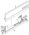
図1は引出しアセンブリを示し、この引出しアセンブリは、前面パネル1、後面パネル(図示せず)、底面パネル3、並びに引出しアセンブリの両側部にあり、前面パネル1と後面パネルとの間に延在する引出し側部4を備える。引出しアセンブリの底面パネル3、前面パネル1、及び後面パネルは慣用の態様で引出し側部4に結合されている。図2に示すように、引出しアセンブリに使用される引出し側部4は、通常、支持ブラケット60a、60b上に嵌合するカバー部分50を備えた、”2重壁(double-walled)”タイプから構成されている。カバー部分50及び支持ブラケット60a、60bは金属で作られていることが好ましい。引出しアセンブリを摺動可能に開閉するガイドレール・システムは、これらの支持ブラケット60a、60b内に配置されている。
FIG. 1 shows a drawer assembly, which is on the
通常、スライディング・ガイドレール・システムは、支持ブラケット60a、60bから構成される開放したC字セクション内に挿入可能な引抜きレール70a、70bを含んでいる。図8A及び図8Bに示されているような、典型的な”完全伸長(full-extension)”スライディング・ガイドレール・システムは、通常、システムを家具の物品に固定するための装着ブラケットと、中間レール10を受容するための装着ブラケットに装着された固定ガイドであって、中間レール10が固定ガイドに対して前後に摺動することができる、前記固定ガイドと、引出しアセンブリに取り付けるための引抜きレール70a、70bであって、引抜きレールは中間レール10上で前後に摺動することができる、前記引抜きレール70a、70bと、を備えている。典型的な”単一伸長(single-extension)”スライディング・ガイドレール・システムは、通常、装着ブラケットの走行面上を前後に摺動することができる引抜きレール70a、70bによって、システムを家具の物品に固定するための装着ブラケットを備えている。
Typically, the sliding guide rail system includes pull-out
図3及び図4に示すように、各々の引出し支持ブラケット60a、60bはシートメタルから、その内側(引出しアセンブリの内側に面する支持ブラケット60a、60bの側)に沿って長さ方向に配置されたL字形状をしたフランジを具備する開放したC字セクションに形成されることが好ましい。引出しアセンブリの底面パネル3はL字形状をしたフランジの水平部分62上に装着可能である。これにより、底面パネル3の側部はL字形状をしたフランジの垂直部分61に当接する。支持ブラケット60a、60bの頂面63は支持ブラケット60a、60bを引抜きレール70a、70bに解放可能に係合させるために(図示しない)係合クリップを受容するように構成されている。図8A、図8B及び図8Cは、引抜きレールの垂直フランジ72と、L字形状をしたフランジの垂直部分61との間の、引抜きレール70a、70bの両側に間隙75が存在することを示している。これにより、引抜きレール70a、70bは支持ブラケット60a、60b内で長手方向に直角な横方向に移動可能である。従って、引出しアセンブリの開閉摺動運動は不安定になされている。引抜きレールの摺動運動を案内する手段は、従って、引出しアセンブリの両側に設けられている。
As shown in FIGS. 3 and 4, each
引出しの一側には、平面を具備する一対のガイド突出部64aが、L字形状をしたフランジの垂直部分61aの両方の内側面に設けられている。支持ブラケット60aが摺動ガイドレール・システムによって解放可能に固定されるときに、引抜きレール70aはこれら両方のガイド突出部64aの間に位置している。引抜きレール70aは、このレールが家具の物品内に摺り込むか又は該物品から摺り出すときに、案内突出部64aによってなに直角な横方向に移動されて案内される。レールの摺動運動を可能にするように案内突出部64a及び垂直フランジ70aの間に、引抜きレール70aの各々の側に微小間隙が存在する。好ましくは、支持ブラケット60aには、その前面及び後面の長手方向端部の両方に一対の案内突出部64aが設けられており、従って、引抜きレール70aが長手方向端部の両方で案内されることを可能にしている。支持ブラケット60a上のこれらの案内突出部64aにより、引抜きレール70aに対する支持ブラケット60aの位置が固定され、すなわち、調節不可能になされている。
On one side of the drawer, a pair of
(図8A、図8B及び図8Cで示される)従来技術で周知なように、引出し組立体の底面パネル3及び/又は家具の物品の幅は、特別な場合に、所望の予め定めた寸法から異なり、距離P1又はP2の変動に帰着する。P2の全長は引出しアセンブリの底面パネル3の長さの変動に従って変化し、かつP1の全長は家具の物品の寸法の変動に従って変化する。P1及びP2の長さのこうした変動は引抜きレール70bに対する支持ブラケット60bの位置を調節することによって適合させることができる。
As is well known in the prior art (shown in FIGS. 8A, 8B and 8C), the width of the bottom panel 3 of the drawer assembly and / or the furniture article can be reduced from the desired predetermined dimensions in special cases. Differently, it results in a variation of the distance P1 or P2. The total length of P2 varies according to variations in the length of the bottom panel 3 of the drawer assembly, and the total length of P1 varies according to variations in the dimensions of the furniture article. Such variations in the lengths of P1 and P2 can be accommodated by adjusting the position of the
従って、支持ブランケット60aとは異なり、支持ブラケット60b(図3及び図4)には、引抜きレール70bに対して支持ブラケット60bの位置を調製可能にするために、ガイド突出部を備えていない。引抜きレール70aのみが支持ブラケット60a内で長手方向に直角な横方向の変位に対して案内され、かつ引抜きレール70bが支持ブラケット60bの中に案内されない場合、引出しアセンブリは、自身が開閉されるときに傾斜するか又は反れる傾向がある。このように、引抜きレール70bの支持ブラケット60b内での長手方向に直角な横方向の変位を克服し、かつ支持ブラケット60bの引抜きブラケット70bに対する調節を可能にするために、スタビライザー装置8がこの支持ブラケット60bの前部に向かって設けられている。スタビライザー装置8を収容するために、支持ブラケット60bには、その頂面63に、スロット65及び一対のエッジ開口66bが設けられている。各エッジ開口66bは支持ブラケットの頂面63の側部エッジに配置されている。更に、引抜きレール70bにはその長手方向端部に凹所71bが設けられている。
Therefore, unlike the
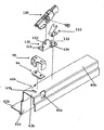
図6A及び図6Bは、支持ブラケット60bの引抜きレール70bに対する位置を長手方向に直角な横方向に調節可能にする一方で引抜きレール70bの運動を支持ブラケット60b内に案内するスラビライザー装置8を示している。スタビライザー装置8は、安内ブラケット90と、レバー100と、コネクター110と、ホルダー・ブラケット120と、を備える。
FIGS. 6A and 6B show the stabilizer device 8 that allows the position of the
図5Aに示されている、ガイドブラケット90は金属製であることが好ましく、かつフランジ91の両側に配置された一対の脚92を具備する水平フランジ91を含んでいる。
中央に位置する突起93水平フランジ91の後部エッジから突出する。突起93は前記支持ブラケット溝65b内に係合可能であり、かつ脚92は支持ブラケットエッジ開口66b内に挿入可能であり、従って、案内ブラケット90を支持ブラケット60b上に装着ししている。突起93が溝65b内で長手方向に直角な横方向に移動可能であるように、支持ブラケット溝65bの幅は案内ブラケット突起93の幅に対して過大寸法になされている。このように、案内ブラケット90は、支持ブラケット60b上に装着された後に長手方向に直角な方向に調節可能である。支持ブラケット溝65bによって、案内ブラケット突起93は引抜きレール70bの凹所71b内に固定される。引抜きレールの凹所71bの幅及び案内ブラケット突起93の幅は、突起93が凹所71b内で締まり嵌めであるように選択されている。要するに、突起93は、スロット65b内で長手方向に直角方向に移動可能であるが、凹所71b内では移動可能ではない。結局、スロット65b内の突起93の長手方向に直角な横方向の運動は長手方向に直角な横方向に調製された引抜きレール70bに対して支持ブラケット60bの位置に帰着する。
The
The
引抜きレール70bの両側では、案内ブラケット90の各脚92は引抜きレール70bの垂直フランジ72bとL字形状フランジの垂直部分61bの内側面との間の間隙75b内に位置する。このように、引抜きレール70bは、支持ブラケット60b内で、懸下する案内ブラケットの脚92の間に案内すなわち保持される。
On both sides of the pull-out
案内ブラケット90には、その水平フランジ91の底面上の(図5Bに示されるような)グリップ部分94も設けられている。好ましくは、このグリップ部分94は、案内ブラケットの水平フランジ91の下に嵌合されている保持部分によって保持部片96上へ固定された弾発性材料部片95を含む。保持部片96には、水平フランジ91上の一対の対応する開口91内に嵌合する一対のコネクター96aが設けられている。弾発性材料部片95がゴムから成り、かつ保持部片96がプラスチック製であることが好ましい。明らかに、このグリップ部分94は、ブラケットを支持ブラケット60b上に装着する前に、案内ブラケット90上に嵌合されるべきである。案内ブラケット90のグリップ部分94は支持ブラケット60bの頂面63bと接触しており、このとき、ブラケット90はその上に装着されている。結果として得られるグリップ力は支持ブラケット60b上への案内ブラケット90の錠止をする支援をする。しかしながら、グリップ部分94の結果として得られる性質は、案内ブラケット90が支持ブラケット60bによって錠止された後でさえ僅かに長手方向に直角な横方向への調整を可能にしている。本願発明では、ゴムと類似した把持能力を有する何れかの弾発性材料を使用することができる。上述したように、把持部分94は案内ブラケット90とは別の構造として配置されているが、把持部分94が案内ブラケット90と一体になされることも可能である。
The
レバー100(図6A及び図6B)は第1の長手方向端部における一対の外向きに延在する平坦なフラップ101と、第2の長手方向端部における一対の前縁延長部102と、を具備する逆U字形状をしたブラケットである。レバー100には、中央に位置するホール103が更に設けられている。
The lever 100 (FIGS. 6A and 6B) includes a pair of outwardly extending
支持ブラケットのスロット65b及びエッジ開口66bの前方には、レバー100が、支持ブラケット60bの頂面63b上へ(好ましくは溶接によって)固定されるホルダー・ブラケット120(図4)上に支持される。ホルダー120は垂直なフランジ121及び水平なフランジ122を具備する。垂直なフランジ121はレバー100の凹所内に挿入可能である。ホルダー120の垂直フランジ121には中央レバー穴103に対応する穴123が設けられている。レバー100は、ホルダー・ブラケット及びレバー穴123、103によって、ネジ又はリベットによってホルダー・ブラケット上に回動可能に固定されている。一対のロケータ124ホルダー・ブラケット120の水平フランジに設けられている。
In front of the
水平部分111及び角度が付けられた部分112を含むコネクター110はホルダー・ブラケット120(図4、図6A及び図6B)上に係合されている。穴113は、ホルダー120の水平フランジ122上のロケータ124と係合させるためのコネクター110の水平部分111上に設けられている。コネクター110の角度が付けられた部分112は一対の離隔配置された延長部114に終端する。これらのコネクタ延長部114はレバー100の前縁延長部上にクリップ留めされ、レバー100の第2の端部をこれらの間に固締する。上向きの力がコネクター110によって(前縁延長部102によって)レバー第2端部に働き、(外向きに延在する平坦なフラップ101によって)レバーの第1の端部を下向きに偏倚させる。案内ブラケット90に対するレバー100のロケーションは、2つの外向きに延在するフラップ101が案内ブラケットのフランジ91の頂部に位置づけられるようなものである。レバー100の第1の端部100が下向きに偏倚されることによって、一定の圧力がレバーのフラップ101によって案内ブラケットの水平フランジ91上に働き、こうして、案内ブラケット90が支持ブラケット60bから垂直方向に上昇しないように阻止する。要するに、案内ブラケット90は支持ブラケット60b上に錠止される。
A
スタビライザー装置8(案内ブラケット90、レバー100、コネクター110及びホルダー・ブラケット120)が支持ブランケット60b上に錠止されたあと、図9に示すように、支持ブラケット60bは引抜きレール70bに固定される。第1に、引抜きール70bは家具から引き抜かれる。その後、引出しアセンブリ(底面パネル3は支持ブラケットのL字形状をしたフランジの水平部分62b上に着座する)は家具に物品内に押し込まれる。引出し組立体が閉じる運動をする間に、支持ブラケットのスロット65bを通じて下向きに突出する案内ブラケットの突出部93は引抜きレールの凹所71b内に係合し且つ固定される。引抜きレールの凹所71bの内側側方エッジは、該エッジが長手方向の凹所71b内に押し込まれるにつれて、案内ブラケット突出部93を案内するように角度が付けられている。一旦、案内ブラケットの突出部93が凹所71b内に固定されると、引抜きレール70bの摺動運動は支持ブラケット60bと整合するように案内される。引抜きレールの凹所71bの幅及び案内ブラケットの突出部93の幅がほとんど類似しているとき、突出部93は一旦挿入されると凹所71b内でしっかりと保持されている。さらに、支持ブラケット60bを引抜きレール70bと解放可能に係合させる係合クリップ(図示せず)は引抜きレール70bの引き続く摺動運動の間中に凹所71b内にしっかりと係合したままであることも保証する。
After the stabilizer device 8 (the
案内ブラケット90はレバー100、コネクター110及びホルダー・ブラケット120の後方に位置し、支持ブラケットのスロット65bは図3に示されているように、エッジ開口66bの後方に位置することが好ましい。あるいは、案内ブラケット90はレバー100、コネクター110及びホルダー・ブラケット120の前方に位置することも可能であり、この場合、支持ブラケット65bはエッジ開口66bの前方に位置するべきである。
The
本願明細書で使われた全ての方向に関する、例えば、前面/前方に、後方に/後部、頂部、底部、長手方向に直角な横方向に、垂直に、内向きに、外向きに、のような言葉使いは使用時の引出しアセンブリの配向に対するものである。 For all directions used herein, for example, front / front, back / back, top, bottom, laterally perpendicular to the longitudinal direction, vertically, inward, outward, etc. The terminology is relative to the orientation of the drawer assembly in use.
当業者には容易に理解できるように、本発明は本発明の範囲又は必須の特徴から逸脱しない範囲で他の特定の形態で容易に作り出し得る。本発明の実施形態は、従って、単なる例示的なものであり限定的なものではないものと考えられる。本発明の範囲は上述した発明の詳細な説明よりはむしろ特許請求の範囲によって示されており、そして、特許請求の範囲内での全ての変更は特許請求の範囲に含まれることをように意図されている。 As will be readily appreciated by those skilled in the art, the present invention may be readily produced in other specific forms without departing from the scope or essential characteristics of the invention. Embodiments of the present invention are therefore considered to be exemplary only and not limiting. The scope of the invention is indicated by the following claims rather than by the foregoing detailed description of the invention, and all modifications within the scope of the claims are intended to be embraced therein. Has been.
1 前面パネル
3 底面パネル
4 引出し側部
8 スタビライザー装置
10 中間レール
50 カバー部分
60a、60b 支持ブラケット
61a、61b フランジの垂直部分
63b 頂面
64a ガイド突出部
65b スロット
66b エッジ開口
70a、70b 引抜きレール
71b 引抜きレールの凹所
90 案内ブラケット
91 フランジ
92 脚
93 突起
94 グリップ部分
95 弾発性材料部片
96 保持部片
96a コネクター
100 レバー
101 フラップ
102 前縁延長部
103 中央レバー穴
110 コネクター
111 水平部分
112 或る角度で曲げられた部分
113 穴
114 延長部
121 垂直なフランジ
122 水平フランジ
123 穴
124 ロケータ
DESCRIPTION OF
Claims (10)
引出し及び前記引出しを家具の物品内で摺動可能に開閉するための摺動ガイドレール・システムと、
前記引出しを支持するための2つの支持ブラケット(60a、60b)であって、前記引出しの各側には、前記2つの支持ブラケット(60a、60b)のうちの1つが設けられ、前記摺動ガイドレール・システムは前記各支持ブラケット内に配置された引抜きレール(70a、70b)を含んでおり、前記2つの支持ブラケット(60a、60b)のうちの一方の支持ブラケット(60b)はスロット(65b)を具備し、及び前記一方の支持ブラケット(60b)内に配置された前記引抜きレール(70b)は凹所(71b)を具備する、前記2つの支持ブラケット(60a、60b)と、
前記引出しの摺動運動を安定化させるためのスタビライザー装置(8)であって、前記スタビライザー装置は案内ブラケット(90)及びレバー(100)を含んでおり、
前記案内ブラケットは前記一方の支持ブラケットのスロット(65b)内で係合可能な突出部(93)を具備し、前記スロットの幅は前記案内ブラケットの突出部(93)の幅を越える寸法とされ、これにより、前突出部は前記スロット内で長手方向に直角な方向に移動可能であり、
前記案内ブラケットの突出部(93)は前記一方の支持ブラケットのスロット(65b)を通じて前記引抜きレールの凹所(71b)内に固定され、これにより、前記スロット(65b)内の前記突出部(93)の長手方向に直角な横方向の運動は前記一方の支持ブラケット(60b)に対する前記引抜きレール(70b)の位置を調整する、前記スタビライザー装置と、を備える引出しアセンブリにおいて、
前記スタビライザー装置(8)は、前記レバー(100)を前記案内ブラケット(90)に作動連結させる弾発性コネクター(110)を更に含み、これにより、前記レバーは前記一方の支持ブラケット(60b)上に前記案内ブラケットを錠止すべく偏倚され、及び
前記案内ブラケット(90)は、該案内ブラケット(90)が前記一方の支持ブラケット(60b)上に錠止されるときに、前記案内ブラケットの突出部(93)が前記一方の支持ブラケットのスロット(65b)内で長手方向に直角な横方向に調整可能であることを可能にする弾発性グリップ部分(94)を具備することを特徴とする引出しアセンブリ。 A drawer assembly,
A sliding guide rail system for slidably opening and closing the drawer and the drawer in a furniture article;
A two support brackets for supporting the front Symbol drawer (60a, 60b), on each side of the drawer, the two support brackets (60a, 60b) one of the provided, said slide The guide rail system includes a pull-out rail (70a, 70b) disposed in each of the support brackets, and one of the two support brackets (60a, 60b) has a slot (65b). ), And the pull-out rail (70b) disposed in the one support bracket (60b ) includes a recess (71b), the two support brackets (60a, 60b),
A stabilizer device (8) for stabilizing the sliding movement of the drawer, the stabilizer device comprising a guide bracket (90) and a lever ( 100 ),
The guide bracket includes a protrusion (93) that can be engaged in the slot (65b) of the one support bracket, and the width of the slot exceeds the width of the protrusion (93) of the guide bracket. This allows the front projection to move in a direction perpendicular to the longitudinal direction within the slot,
The protrusion (93) of the guide bracket is fixed in the recess (71b) of the pull-out rail through the slot (65b) of the one support bracket, and thereby, the protrusion (93) in the slot (65b). And a stabilizer device for adjusting the position of the pull-out rail (70b) relative to the one support bracket (60b) by a lateral movement perpendicular to the longitudinal direction of the pull-out assembly.
The stabilizer device (8) further includes a resilient connector (110) operatively connecting the lever (100) to the guide bracket (90), whereby the lever is mounted on the one support bracket (60b) . The guide bracket (90) is biased to lock the guide bracket, and the guide bracket (90) protrudes when the guide bracket (90) is locked onto the one support bracket (60b). The part (93) is provided with a resilient grip part (94) that allows it to be adjusted laterally perpendicular to the longitudinal direction in the slot (65b) of said one support bracket. Drawer assembly.
前記水平部分は前記ホルダー・ブラケット(120)上に固着され、かつ前記或る角度で曲げられた部分は前記レバー(100)の端部上にクリップ留めするように構成され、これにより、一定の上向きの力が前記端部において前記レバーに働く、請求項2に記載の引出しアセンブリ。 The resilient connector (110) comprises a horizontal part (111) and a part bent at an angle (112),
The horizontal portion is fixed on the holder bracket (120), and the bent portion is configured to clip onto the end of the lever (100), thereby providing a constant The drawer assembly of claim 2, wherein an upward force acts on the lever at the end.
Applications Claiming Priority (2)
| Application Number | Priority Date | Filing Date | Title |
|---|---|---|---|
| MYPI20071294A MY142138A (en) | 2007-08-06 | 2007-08-06 | Drawer assembly |
| MYPI20071294 | 2007-08-06 |
Publications (2)
| Publication Number | Publication Date |
|---|---|
| JP2009039514A JP2009039514A (en) | 2009-02-26 |
| JP5529397B2 true JP5529397B2 (en) | 2014-06-25 |
Family
ID=40020259
Family Applications (1)
| Application Number | Title | Priority Date | Filing Date |
|---|---|---|---|
| JP2008162511A Expired - Fee Related JP5529397B2 (en) | 2007-08-06 | 2008-06-20 | Drawer assembly |
Country Status (9)
| Country | Link |
|---|---|
| US (1) | US7980642B2 (en) |
| EP (1) | EP2022371B1 (en) |
| JP (1) | JP5529397B2 (en) |
| CN (1) | CN101396207B (en) |
| AT (1) | ATE462324T1 (en) |
| AU (1) | AU2008202546A1 (en) |
| DE (1) | DE602008000887D1 (en) |
| ES (1) | ES2341914T3 (en) |
| MY (1) | MY142138A (en) |
Families Citing this family (10)
| Publication number | Priority date | Publication date | Assignee | Title |
|---|---|---|---|---|
| MY151706A (en) * | 2009-08-12 | 2014-06-30 | Harn Marketing Sdn Bhd | Drawer assembly |
| AT511417B1 (en) * | 2011-04-27 | 2018-08-15 | Blum Gmbh Julius | DRAWER WALL WITH AN INTERNAL WALL AND AN EXTERNAL WALL |
| AT511418B1 (en) * | 2011-05-05 | 2014-11-15 | Blum Gmbh Julius | EXTRACTION GUIDE FOR A DRAWER |
| US8231188B1 (en) * | 2011-07-15 | 2012-07-31 | King Slide Works Co., Ltd. | Support mechanism for slide assembly |
| AT515690B1 (en) * | 2014-06-23 | 2015-11-15 | Fulterer Gmbh | pull-out |
| US9730516B2 (en) * | 2014-09-03 | 2017-08-15 | Apple Inc. | Table mechanisms and structures |
| DE202014104923U1 (en) * | 2014-10-16 | 2016-01-19 | Grass Gmbh | Wall element for a frame and frame, drawer and furniture |
| DE202015104431U1 (en) * | 2015-08-21 | 2016-11-22 | Grass Gmbh | Device for moving a furniture part and furniture |
| DE202015006934U1 (en) * | 2015-10-05 | 2017-01-09 | Grass Gmbh | Device for releasably connecting a movable in a furniture body of a furniture part via a guide unit furniture drawer with the guide unit |
| DE102018104398A1 (en) * | 2018-02-27 | 2019-08-29 | Paul Hettich Gmbh & Co. Kg | Furniture or household appliance and method for mounting a functional unit of a push element in a piece of furniture or household appliance |
Family Cites Families (21)
| Publication number | Priority date | Publication date | Assignee | Title |
|---|---|---|---|---|
| US2992057A (en) * | 1959-06-12 | 1961-07-11 | Brammer Mfg Co | Adjustable guide means for drawers and the like |
| JPS60180517U (en) * | 1984-05-14 | 1985-11-30 | 森 司 | earrings |
| AT399262B (en) | 1989-02-22 | 1995-04-25 | Blum Gmbh Julius | EXTENSION GUIDE SET FOR A DRAWER OD. DGL. |
| US5026176A (en) * | 1989-10-10 | 1991-06-25 | C. J. Management, Ltd. | Extendable rail system |
| DE4114708C2 (en) * | 1991-05-06 | 2000-11-30 | Lautenschlaeger Mepla Werke | Fastening device for rails of drawer pull-out guides |
| AT401713B (en) * | 1993-06-29 | 1996-11-25 | Blum Gmbh Julius | DIFFERENTIAL EXTRACT FOR DRAWERS OD. DGL. |
| DE19531698B4 (en) * | 1995-08-29 | 2005-08-11 | MEPLA-WERKE LAUTENSCHLäGER GMBH & CO. KG | Bracket fitting for front panels of drawers |
| AT409072B (en) * | 1998-06-24 | 2002-05-27 | Blum Gmbh Julius | drawer |
| DE20107278U1 (en) * | 2001-04-27 | 2001-08-02 | Hettich Paul Gmbh & Co | Device for producing a snap connection |
| DE10219448A1 (en) | 2002-05-02 | 2003-11-13 | Grass Gmbh Hoechst | drawer guide |
| MY131063A (en) * | 2002-05-17 | 2007-07-31 | Harn Marketing Sdn Bhd | Guide rails pull-out drawer/equipment |
| MY140924A (en) * | 2003-05-22 | 2010-02-12 | Harn Marketing Sdn Bhd | A drawer stabilizing arrangement for double walled drawer |
| EP1483984B1 (en) * | 2003-06-05 | 2017-08-09 | Grass GmbH | Drawer slide |
| DE20311795U1 (en) * | 2003-07-31 | 2004-11-18 | Alfit Ag | Drawer pull-out guide with automatic retraction with integrated damping |
| MY138757A (en) * | 2003-11-05 | 2009-07-31 | Harn Marketing Sdn Bhd | Drawer pull out guide rail |
| US20050231083A1 (en) * | 2004-04-15 | 2005-10-20 | Garcie Kent C Jr | Undermount drawer slide |
| DE102005007001A1 (en) * | 2005-02-16 | 2006-08-17 | Lautenschläger, Horst | Device for holding a drawer |
| MY144868A (en) * | 2005-02-21 | 2011-11-30 | Harn Marketing Sdn Bhd | "drawer guide rail assembly" |
| MY146313A (en) * | 2005-10-11 | 2012-07-31 | Harn Marketing Sdn Bhd | Sliding guide rail system for a drawer |
| JP3127644U (en) * | 2006-09-28 | 2006-12-07 | 川湖科技股▲分▼有限公司 | Slide rail bracket structure |
| JP3138146U (en) * | 2007-10-11 | 2007-12-20 | 川湖科技股▲分▼有限公司 | Slide rail |
-
2007
- 2007-08-06 MY MYPI20071294A patent/MY142138A/en unknown
-
2008
- 2008-06-10 EP EP08010559A patent/EP2022371B1/en not_active Not-in-force
- 2008-06-10 AT AT08010559T patent/ATE462324T1/en active
- 2008-06-10 DE DE602008000887T patent/DE602008000887D1/en active Active
- 2008-06-10 ES ES08010559T patent/ES2341914T3/en active Active
- 2008-06-10 AU AU2008202546A patent/AU2008202546A1/en not_active Abandoned
- 2008-06-20 JP JP2008162511A patent/JP5529397B2/en not_active Expired - Fee Related
- 2008-06-27 US US12/147,689 patent/US7980642B2/en not_active Expired - Fee Related
- 2008-08-06 CN CN2008101460045A patent/CN101396207B/en not_active Expired - Fee Related
Also Published As
| Publication number | Publication date |
|---|---|
| DE602008000887D1 (en) | 2010-05-12 |
| MY142138A (en) | 2010-09-30 |
| US7980642B2 (en) | 2011-07-19 |
| US20090039746A1 (en) | 2009-02-12 |
| AU2008202546A1 (en) | 2009-02-26 |
| ES2341914T3 (en) | 2010-06-29 |
| EP2022371A1 (en) | 2009-02-11 |
| ATE462324T1 (en) | 2010-04-15 |
| CN101396207B (en) | 2013-05-08 |
| CN101396207A (en) | 2009-04-01 |
| EP2022371B1 (en) | 2010-03-31 |
| JP2009039514A (en) | 2009-02-26 |
Similar Documents
| Publication | Publication Date | Title |
|---|---|---|
| JP5529397B2 (en) | Drawer assembly | |
| US8833878B2 (en) | Drawer guide rail system | |
| EP1692969B1 (en) | Drawer guide rail assembly | |
| CN107529885B (en) | Device and method for fixing a pushing element | |
| US7758135B2 (en) | Sliding guide rail system for a drawer | |
| EP2283744B1 (en) | Drawer assembly | |
| US10314397B2 (en) | Device and method for fixing a push element | |
| US20180153304A1 (en) | Device and method for fixing a push element | |
| EP1336709B8 (en) | Interlock arrangement for preventing the simultaneous opening of vertically stacked drawers | |
| JP2004176262A (en) | Door closing device of sliding door | |
| AU2004241897B2 (en) | A drawer stabilizing arrangement for double walled drawer | |
| EP2322057A1 (en) | Drawer assembly | |
| CN110770493A (en) | Holding piece | |
| US5722749A (en) | Self-positioning cabinet rail for a drawer guide | |
| KR102314062B1 (en) | Under rail guide bracket for drawer | |
| CN113329667A (en) | Drawer | |
| CN115886468A (en) | Drawer system | |
| JPH08154754A (en) | Upper guide device for tray cabinet | |
| JP2000037248A (en) | Guiding device for drawer |
Legal Events
| Date | Code | Title | Description |
|---|---|---|---|
| A621 | Written request for application examination |
Free format text: JAPANESE INTERMEDIATE CODE: A621 Effective date: 20110617 |
|
| A521 | Request for written amendment filed |
Free format text: JAPANESE INTERMEDIATE CODE: A523 Effective date: 20120606 |
|
| A977 | Report on retrieval |
Free format text: JAPANESE INTERMEDIATE CODE: A971007 Effective date: 20130131 |
|
| A131 | Notification of reasons for refusal |
Free format text: JAPANESE INTERMEDIATE CODE: A131 Effective date: 20130305 |
|
| TRDD | Decision of grant or rejection written | ||
| A01 | Written decision to grant a patent or to grant a registration (utility model) |
Free format text: JAPANESE INTERMEDIATE CODE: A01 Effective date: 20140318 |
|
| A61 | First payment of annual fees (during grant procedure) |
Free format text: JAPANESE INTERMEDIATE CODE: A61 Effective date: 20140417 |
|
| R150 | Certificate of patent or registration of utility model |
Ref document number: 5529397 Country of ref document: JP Free format text: JAPANESE INTERMEDIATE CODE: R150 |
|
| R250 | Receipt of annual fees |
Free format text: JAPANESE INTERMEDIATE CODE: R250 |
|
| R250 | Receipt of annual fees |
Free format text: JAPANESE INTERMEDIATE CODE: R250 |
|
| R250 | Receipt of annual fees |
Free format text: JAPANESE INTERMEDIATE CODE: R250 |
|
| R250 | Receipt of annual fees |
Free format text: JAPANESE INTERMEDIATE CODE: R250 |
|
| R250 | Receipt of annual fees |
Free format text: JAPANESE INTERMEDIATE CODE: R250 |
|
| R250 | Receipt of annual fees |
Free format text: JAPANESE INTERMEDIATE CODE: R250 |
|
| LAPS | Cancellation because of no payment of annual fees |