JP5523403B2 - Drilling tool - Google Patents
Drilling tool Download PDFInfo
- Publication number
- JP5523403B2 JP5523403B2 JP2011148020A JP2011148020A JP5523403B2 JP 5523403 B2 JP5523403 B2 JP 5523403B2 JP 2011148020 A JP2011148020 A JP 2011148020A JP 2011148020 A JP2011148020 A JP 2011148020A JP 5523403 B2 JP5523403 B2 JP 5523403B2
- Authority
- JP
- Japan
- Prior art keywords
- blade
- moving shaft
- rod
- shaft
- axial direction
- Prior art date
- Legal status (The legal status is an assumption and is not a legal conclusion. Google has not performed a legal analysis and makes no representation as to the accuracy of the status listed.)
- Active
Links
- 238000005553 drilling Methods 0.000 title claims description 71
- 239000002173 cutting fluid Substances 0.000 claims description 21
- 239000000463 material Substances 0.000 claims description 21
- 238000007789 sealing Methods 0.000 claims description 3
- 239000007787 solid Substances 0.000 claims description 3
- 239000010730 cutting oil Substances 0.000 description 5
- 238000012423 maintenance Methods 0.000 description 5
- 238000004891 communication Methods 0.000 description 1
- 230000006835 compression Effects 0.000 description 1
- 238000007906 compression Methods 0.000 description 1
- 238000012986 modification Methods 0.000 description 1
- 230000004048 modification Effects 0.000 description 1
- 239000011343 solid material Substances 0.000 description 1
Images


Description
本発明は、孔あけ工具に関し、更に詳細には、切削液を円筒状の刃に供給する孔あけ工具に関する。 The present invention relates to a drilling tool, and more particularly to a drilling tool that supplies cutting fluid to a cylindrical blade.
本発明に係わる孔あけ工具は、孔をあけるべき材料の孔あけ面にそれと垂直な軸線に沿う軸線方向に孔をあける中空円筒状の刃と、刃が取付けられ且つ刃と一緒に軸線方向に移動可能な中空の移動軸と、移動軸が軸線方向に移動可能に嵌合する貫通孔を有し且つ刃及び移動軸を軸線を中心に回転させる回転軸を有し、回転軸によって移動軸及び刃を回転させながら、移動軸によって、刃を下降させて、孔あけ面に孔をあける工具である。 A drilling tool according to the present invention includes a hollow cylindrical blade that drills a hole in a drilling surface of a material to be drilled in an axial direction along an axis perpendicular to the drilling surface, and a blade attached to the blade and in the axial direction together with the blade. A movable hollow moving shaft, a through hole in which the moving shaft is fitted so as to be movable in the axial direction, and a rotating shaft that rotates the blade and the moving shaft around the axial line. It is a tool that lowers the blade by a moving shaft while rotating the blade to make a hole in the drilling surface.
従来、切削油等の切削液を円筒状の刃に供給する孔あけ工具が知られている(例えば、特許文献1参照)。特許文献1に記載された孔あけ工具では、ハウジングの上壁に設けられた切削油供給口と、それから移動軸の中に下方に延びる管を有し、切削油供給口に供給された切削油が管の中を通って移動軸の中に供給され、次いで、刃に向かって案内される。
Conventionally, a drilling tool for supplying a cutting fluid such as cutting oil to a cylindrical blade is known (for example, see Patent Document 1). In the drilling tool described in
また、特許文献1に記載された孔あけ工具は、円筒状の刃を回転させながら下降させて孔あけする際に円筒状の刃の中に残った円柱状又は円板状の切屑を、強制的に押出す機構を有している。具体的には、孔あけが終わって刃を上昇させたとき、刃の中心に配置されたセンターピンが上記管によって停止させられ、センターピンが停止した状態で刃が上昇し続けることにより、切屑が刃から押出される。
In addition, the drilling tool described in
特許文献1に記載されている従来の孔あけ工具では、ハウジングに設けられた上記管が移動軸の中に延び、その中を通して切削液が供給されていた。この場合、ハウジングに固定されている上記管と、刃と一緒に回転する移動軸との間に、相対的な回転運動と摺動運動が生じ、管と移動軸との間に設けられたシールが磨耗し、シールを適宜交換する必要があった。また、従来の孔あけ工具では、管が曲がることがあり、その交換が必要なことがあった。
In the conventional drilling tool described in
そこで、本発明の目的は、メンテナンス作業を軽減することができる孔あけ工具を提供することにある。 Then, the objective of this invention is providing the drilling tool which can reduce a maintenance operation | work.
上記目的を達成するために、本発明による孔あけ工具は、孔をあけるべき材料の孔あけ面にそれと垂直な軸線に沿う軸線方向に孔をあける中空円筒状の刃と、刃が取付けられ、刃と一緒に軸線方向に移動可能な中空の移動軸と、移動軸が軸線方向に移動可能に嵌合する貫通孔を有し、且つ、移動軸及び刃を軸線を中心に回転させる回転軸と、回転軸を覆い、且つ、孔あけ面に対して固定されるハウジングと、移動軸及び刃の中に軸線方向に移動可能に配置され、孔あけ面側の第1の端部と、その反対側の第2の端部を有する棒状要素と、棒状要素の第2の端部が当接可能にハウジングに設けられたストッパ部と、を有し、移動軸及び刃を回転させながら移動軸及び刃を軸線方向のうちの第1の向きに移動させ続けて孔あけ面に孔をあけた後、孔あけした材料が刃の中に残っているとき、棒状要素は、刃の中に残っている材料によって移動軸から第1の向きと反対の第2の向きに突出した状態にあり、次いで、移動軸及び刃を第2の向きに移動させたとき、棒状要素の第2の端部がストッパ部に当接して、棒状要素が移動軸及び刃に対して第1の向きに移動し、刃の中に残った材料を刃から押出し、ハウジングは、切削液を供給するための供給孔を有し、供給孔から供給された切削液は、棒状要素と移動軸の間の隙間、及び、棒状要素と刃の間の隙間を通って、前記刃に供給されることを特徴としている。 In order to achieve the above object, a drilling tool according to the present invention is provided with a hollow cylindrical blade that opens a hole in an axial direction along an axis perpendicular to a drilling surface of a material to be drilled, and the blade is attached. A hollow moving shaft that is movable in the axial direction together with the blade, a rotation shaft that has a through hole in which the moving shaft is movably fitted in the axial direction, and that rotates the moving shaft and the blade about the axis. , A housing that covers the rotation shaft and is fixed to the drilling surface, and is arranged to be movable in the axial direction in the moving shaft and the blade, and the first end on the drilling surface side and vice versa A rod-shaped element having a second end portion on the side, and a stopper portion provided on the housing so that the second end portion of the rod-shaped element can come into contact therewith. After continuing to move the blade in the first direction of the axial direction to make a hole in the drilling surface, When opened the material remaining in the blade, the rod-like element is in the state of protruding from the moving shaft to the second orientation opposite the first orientation by the material remaining in the blade, then the mobile When the shaft and the blade are moved in the second direction, the second end of the rod-shaped element comes into contact with the stopper portion, and the rod-shaped element moves in the first direction with respect to the moving shaft and the blade. The material remaining inside is extruded from the blade, and the housing has a supply hole for supplying a cutting fluid, and the cutting fluid supplied from the supply hole is a gap between the rod-shaped element and the moving shaft, and the rod-shaped element. The blade is supplied to the blade through a gap between the blade and the blade.
上記のように構成された孔あけ工具によれば、移動軸及び刃を回転させながら移動軸及び刃を第1の向きに移動させ続けて孔あけ面に孔をあけた後、孔あけした材料が刃の中に残っているとき、棒状要素は、刃の中に残っている材料によって移動軸から第2の向きに突出した状態にある。棒状要素と移動軸の間には、切削液を供給するための隙間が設けられているので、棒状要素と移動軸の間にシールを設ける必要はない。従って、特許文献1に記載された孔あけ工具において管と移動軸との間に設けられたシールは不要であり、その結果、メンテナンス作業を軽減することができる。
According to the drilling tool configured as described above, the drilled material is formed by continuously moving the moving shaft and blade in the first direction while rotating the moving shaft and blade, and then drilling a hole in the drilling surface. Is left in the blade, the rod-like element is in a state of protruding from the movement axis in the second direction by the material remaining in the blade. Since a gap for supplying cutting fluid is provided between the rod-shaped element and the moving shaft, it is not necessary to provide a seal between the rod-shaped element and the moving shaft. Therefore, the seal provided between the tube and the moving shaft in the drilling tool described in
本発明による孔あけ工具の実施形態において、好ましくは、棒状要素は中実である。 In an embodiment of the drilling tool according to the invention, preferably the rod-like element is solid.
特許文献1に記載された従来の孔あけ工具では、ハウジングに設けられた上記管が曲がることがあった。これに対して、上記のように構成された孔あけ工具によれば、移動軸に対して相対移動する棒状要素が中実であるので、棒状要素がストッパ部材に当接するときの衝撃に対する耐性が向上し、棒状要素が曲がりにくくなっている。その結果、メンテナンス作業を軽減することができる。
In the conventional drilling tool described in
本発明による孔あけ工具の実施形態において、好ましくは、移動軸と回転軸との間に、シール部材が設けられる。 In the embodiment of the drilling tool according to the present invention, a sealing member is preferably provided between the moving shaft and the rotating shaft .
このように構成された孔あけ工具によれば、回転軸と移動軸の間のシール部材において摺動部分が生じるが、移動軸は回転軸と一緒に回転するので、シール部材の磨耗は、移動軸と回転軸との間の軸線方向の相対移動によるものだけである。従って、特許文献1に記載された孔あけ工具の上記部分の磨耗よりも磨耗が軽減され、メンテナンス作業を軽減することができる。
According to the drilling tool configured as described above, a sliding portion is generated in the seal member between the rotating shaft and the moving shaft. However, since the moving shaft rotates together with the rotating shaft , the wear of the seal member is moved. It is only due to the relative movement in the axial direction between the shaft and the rotary shaft . Therefore, wear is reduced more than the wear of the above-described portion of the drilling tool described in
本発明による孔あけ工具は、メンテナンス作業を軽減することができる。 The drilling tool according to the present invention can reduce maintenance work.
以下、図面を参照して、本発明による孔あけ工具の実施形態を説明する。 Embodiments of a drilling tool according to the present invention will be described below with reference to the drawings.
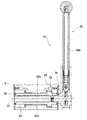
図1及び図2に示すように、孔あけ工具1は、孔をあけるべき材料の孔あけ面Sにそれと垂直な軸線1aに沿う軸線方向Aに孔Hをあける中空円筒状の刃2と、刃2が取付けられ且つ刃2と一緒に軸線1aに沿って移動可能な中空の移動軸4と、移動軸4が軸線方向Aに移動可能に嵌合する貫通孔6aを有し且つ刃2及び移動軸4を軸線1aを中心に回転させる回転軸6と、回転軸6を覆い且つ孔あけ面Sに対して固定されるハウジング8を有している。ハウジング8は、磁気式固定装置等の固定装置8aを介して孔あけ面Sに取外し可能に固定されることが好ましい。本実施形態では、軸線方向Aは、上下方向である。また、移動軸4及び刃2が孔あけ面Sに近づく方向を第1の向き又は下向きA1とし、第1の向きと反対の方向を第2の向き又は上向きA2とする。
As shown in FIGS. 1 and 2, a
孔あけ工具1はまた、回転軸6を回転させる回転駆動機構10を有している。図2に示すように、回転駆動機構10は、モータ12と、その出力軸12aからの回転が伝達される平歯車13と、平歯車13が固定され且つ孔あけ面Sと平行な軸線14を中心に回転可能な駆動軸15と、駆動軸15に固定された第1のベベルギヤ16と、第1のべベルギヤ16と噛合い且つ回転軸6に固定された第2のベベルギヤ17を有している。回転軸6は、第2のベベルギヤ17を軸線方向Aに貫き、第2のベベルギヤ17の両側に配置されたベアリング18によって支持されている。
The
移動軸4は、例えば、スプラインを有し、回転軸6の貫通孔6aは、このスプラインに嵌合する部分を有している。また、移動軸4は、刃2が着脱可能に固定されている第1の部分又は下部分4aと、回転軸6の貫通孔6aに沿って摺動自在な第2の部分又は上部分4bとを有している。下部分4aの外径は、上部分4bの外径よりも大きくなっている。
The moving
孔あけ工具1はまた、移動軸4を軸線方向に移動させる移動機構20を有している。図2〜5に示すように、移動機構20は、移動軸4の下部分4aに取付けられたブラケット22と、ブラケット22に設けられ且つ軸線方向Aに延びるラック23と、ラック23に噛合うピニオン24と、ピニオン24が固定された中空軸25と、中空軸25を回転させる移動ハンドル26とを有している。
The
ブラケット22は、軸線1aに対して垂直に延び且つベアリング27を介して移動軸4に取り付けられた板状の横断部分22aと、軸線1aと平行に延びる軸線方向部分22bを有している。軸線方向部分22bは、矩形の断面を有し、ハウジング8に設けられた矩形の孔28に、軸線方向Aに摺動自在に受入れられている。ラック23は、ブラケット22の軸線方向部分22bに形成されている。
The
中空軸25は、軸線1a及び軸線14に対して垂直な軸線30を中心に回転可能にハウジング8に支持され、且つ、ハウジング8内に収容されている。中空軸25は、ハウジング8から突出せず、ハウジング8、中空軸の両側に孔8bを有することが好ましい。移動ハンドル26は、中空軸25の貫通孔25aに取外し可能に挿入される軸部26aと、軸部26aの端部からそれに対して垂直方向に延びるハンドル部26bとを有している。軸部26aの断面は、例えば、六角形であり、中空軸25の貫通孔25aの断面は、軸部26aに嵌合する形状を有している。軸部26aは、移動ハンドル26を中空軸25に挿入した後それから抜けにくくする引掛り部32を有している。引掛り部32は、例えば、中空軸25にも受けられた凹部に向かってばねによって付勢される小さいボールである。
The
図7に示すように、移動軸4の貫通孔34は、後述する刃2の取付け部2bを受入れる内径を有し且つ第1の端部又は下端34aから上向きA2に第1の段部34cまで延びる第1の部分又は下部34bと、第1の段部34cから上向きA2に第2の段部34eまで延び且つ下部34bよりも小さい内径を有する第2の部分又は中間部34dと、第2の段部34eから上向きA2に第2の端部又は上端34gまで延び且つ中間部34dよりも小さい内径を有する第3の部分又は上部34fとを有している。環状のシール部材34hが、貫通孔34の第1の段部34cに当接するように挿入され、ストップリング34iによって保持されている。
As shown in FIG. 7, the through
孔あけ工具1は更に、刃2及び移動軸4の中に軸線方向Aに移動可能に配置された棒状要素36を有している。棒状要素36は、孔あけ面S側の第1の端部又は下端部36aと、その反対側の第2の端部又は上端部36bを有している。本実施形態では、棒状要素36は、主に刃2の中に配置されるセンターピン38と、移動軸4の中に配置される棒部材40とによって構成されている。従って、センターピン38の孔あけ面S側の端部が第1の端部又は下端部36aを構成し、棒部材40の孔あけ面S側と反対側の端部が第2の端部又は上端部36bを構成する。センターピン38と棒部材40は、別部品で作られているが、作動中、互いに当接したままであるため、一体部品として作られてもよい。
The
刃2は、軸線1aと同心の刃先を有する円筒状の刃本体2aと、刃本体2aから上向きA2に延び且つ移動軸4の貫通孔34の下部34bに嵌合して側方からネジ等によって固定される取付け部2bとを有している。取付け部2bは、その中心に軸線方向Aに延びる円形のピン用貫通孔2cを有し、このピン用貫通孔2cに、センターピン38が軸線方向Aに摺動自在に挿入されている。
The
センターピン38は、ピン用貫通孔2eに嵌合し且つ刃2よりも長い軸線方向長さを有する本体部38aと、本体部38aから上向きA2に延び且つ本体部38aよりも径が大きい拡径部38bとを有している。本体部38aには、軸線方向Aに延びる平らな面38cが形成され、平らな面38cと刃2のピン用貫通孔2cの間には、切削液が流れることが可能な隙間G1が形成される。それにより、移動軸4の貫通孔34は、刃本体2aの内部と連通する。拡径部38bは、移動軸4の貫通孔34に挿入されており、上述した棒部材40と当接している。また、拡径部38bは、それが下向きA1に摺動して刃2に当接するとき、センターピン36の更なる下向きA1の摺動が阻止されると共に、拡径部38bがシール部材34hと全周にわたって係合して移動軸4の貫通孔34と刃本体2aの内部との連通を遮断するように構成されている。
The
棒部材40は、貫通孔34の中間部34dの中を摺動可能な第1の部分又は下部40aと、貫通孔の上部34fの中を摺動可能な第2の部分又は上部40bを有している。下部40aの径は、上部40bの径よりも大きくなっている。貫通孔34の中間部34dにおける棒部材40の下部40aと移動軸4との間、及び、貫通孔34の上部34fにおける棒部材40の上部40bと移動軸4との間にはそれぞれ、切削液が流れることが可能な隙間G2、G3が形成されている。本実施形態では、上部34fの断面は六角形である。
The
貫通孔34の中間部34d内には、棒部材40を移動軸4に対して下向きA1に付勢するばね44が挿入されている。ばね44は、第2の段部34eと棒部材40の下部40aとに当接した圧縮ばねである。
A
孔あけ工具1は更に、棒状要素36の第2の端部36bが当接可能にハウジング8に設けられたストッパ部46を有している。本実施形態では、ハウジング8の壁に設けられたボルトヘッドであり、移動軸4の貫通孔34の上部34f内に挿入可能な径を有している(図2参照)。また、ハウジング8は、好ましくはストッパ部46の近傍に、切削液を供給するための供給孔48を有している。切削液は、切削油であってもよいし、水溶性の切削液であってもよい。
The
移動軸4の、刃2と反対側の端部又は上端部には、回転軸6と移動軸4との間をシールするためのシール部材であるOリング50(図2参照)が設けられている。このOリング50は、移動ハンドル26から手を離しても移動軸4が軸線方向Aに自由に移動しないようにする摩擦力を付与する機能も有している。
An O-ring 50 (see FIG. 2), which is a seal member for sealing between the
次に、本発明による孔あけ工具の動作を説明する。 Next, the operation of the drilling tool according to the present invention will be described.
移動ハンドル26が取り付けられていない場合には、移動ハンドル26の軸部26aを、引掛り部32が中空軸25に引掛るようになるまで、中空軸25の貫通孔25aに挿入することによって、移動ハンドル26を中空軸25に取付ける。中空軸25の両側にハウジング8の孔8bが設けられているので、例えば、右利きまたは左利きの作業者に応じて、移動ハンドル26を任意の側から中空軸25に挿入することができる。また、軸部26aの断面が6角形であるので、中空軸25の貫通孔25aに嵌合する任意の6つの角度で、移動ハンドル26を中空軸25に取り付けることができる。
When the moving
図2に示すように、刃2が孔あけ面Sから離れた位置にあるとき、棒部材40は、ばね44によって移動軸4及び刃2に対して下向きA1に付勢され、センターピン38は、刃2から突出している。棒部材40の上部40bは、貫通孔34の上部34fに位置している。また、センターピン38の拡径部38bは、刃2の取付け部2bに当接し、拡径部38bとシール部材34hの間の密封により、移動軸4の貫通孔34と刃本体2aの内部との流通が遮断され、切削液が移動軸4から刃2に流れないようになっている。
As shown in FIG. 2, when the
モータ12を作動させ、回転軸6によって移動軸4及び刃2を回転させながら、移動ハンドル26によって移動軸4及び刃2を下向きA1に移動させ、センターピン38を材料に接触させる。更に、移動軸4及び刃2を下向きA1に移動させ続けると、棒部材40がばね44に抗して移動軸4及び刃2に対して上向きA2に移動し、移動軸4から上向きA2に突出した状態になる。また、センターピン38の拡径部38bは、刃2の取付け部2bから離れ、移動軸4の貫通孔34と刃本体2aの内部の間の切削液の流通が可能になる。
While the
供給孔48に切削液を、例えば手動で供給すると、切削液は、貫通孔34の上部34fにおける棒部材40の上部40bと移動軸4との間の隙間G3、移動軸4の貫通孔34、貫通孔34の中間部34dにおける棒部材40の下部40aと移動軸4との間の隙間G2、センターピン38と刃2の間の隙間G1を通って、刃2の刃先に供給される。
The cutting fluid supply holes 48, for example, manually supplied, the cutting fluid, the gap G3 between the top 40b of the
移動軸4及び刃2を回転させながら、移動軸4及び刃2を更に下向きA1に移動させ続けることによって、孔あけ面Sに孔Hをあけることができる。
By continuously moving the moving
孔あけした材料(切屑)が切り離されて落下したとき、棒部材40は、ばね44によって移動軸4及び刃2に対して下向きA1に移動し、センターピン38が再び刃2から突出する。また、センターピン38の拡径部38bは、刃2の取付け部2bに当接し、拡径部38bとシール部材34hの間のシールにより、移動軸4の貫通孔34と刃本体2aの内部との流通が遮断され、移動軸4から刃2への切削液の流れが停止される。
When the drilled material (chip) is cut and dropped, the
孔あけした材料(切屑)が切り離されても刃2の中に残って落下しないとき、棒部材40は、刃2の中に残っている材料によって、移動軸4及び刃2に対して上向きA2に移動したままであり、移動軸4から突出したままである。
When the drilled material (chips) is cut off and remains in the
移動ハンドル26によって、移動軸4及び刃2を上向きA2に移動させて戻すと、棒部材40の第2の端部36bがストッパ部46に当接して、棒部材40及びセンターピン38が移動軸4及び刃2に対して下向きA1に移動し、センターピン38が刃2の中の材料(切屑)を刃2から押出す。
When the moving
このように構成された孔あけ工具1において、移動ハンドル26の軸部26aが、中空軸25に対して取外し可能である。移動ハンドル26を取外したとき、中空軸25は、ハウジング8から出張らない。これに対して、特許文献1では、ハンドルを取外したとき、ハンドル用の軸がハウジングから出張っている。従って、本発明による孔あけ工具1は、特許文献1に記載された孔あけ工具よりもコンパクトに収納することが可能である。
In the
移動軸4の軸線方向Aの移動は、ブラケット22の軸線方向部分22bによって案内される。軸線方向部分22bは、板状であり、孔あけ工具1の幅方向にわたって延びている。従って、移動軸4の軸線方向Aに対する傾きを確実に支持することが可能である。
The movement of the moving
棒部材40が、移動軸4に対して軸線方向Aに移動するとき、棒部材40と移動軸の間に隙間G2、G3があるため、棒部材40と移動軸4との間の磨耗はあまり生じない。また、棒部材40は移動軸4と一緒に回転するので、棒部材40と移動軸4との間に磨耗があるとしても、それは、棒部材40と移動軸4の間の軸線方向Aの相対移動によるものだけである。これに対して、特許文献1に記載された孔あけ工具において、ハウジングに固定された管と回転している移動軸との間の磨耗は、回転と軸線方向の相対移動の両方によるものである。したがって、本願発明による孔あけ工具のかかる部分の磨耗は、特許文献1に記載された孔あけ工具のかかる部分の磨耗よりも軽減される。なお、本実施形態において、Oリング50のところに摺動部分があるが、移動軸4は回転軸6と一緒に回転するので、Oリング50の磨耗は、移動軸4と回転軸6との間の軸線方向Aの相対移動によるものだけであり、特許文献1に記載された孔あけ工具の上記部分の磨耗よりも軽減される。
また、棒部材40は、中実材料で形成されている。従って、回転している棒状要素36(棒部材40)の第2の端部36bがストッパ部46に当接するときの両部材の衝撃に対する耐性は、特許文献1に記載された孔あけ工具において回転している中空の管に棒部材が当接するときの両部材の衝撃に対する耐性よりも大きくなる。
Further, the
以上、本発明の実施形態を説明したが、本発明は、以上の実施の形態に限定されることなく、特許請求の範囲に記載された発明の範囲内で種々の変更が可能であり、それらも本発明の範囲内に包含されるものであることはいうまでもない。 Although the embodiments of the present invention have been described above, the present invention is not limited to the above-described embodiments, and various modifications are possible within the scope of the invention described in the claims. Needless to say, these are also included within the scope of the present invention.
本実施形態において、軸線方向Aは、上下方向であるが、切削液が供給孔48から刃2に供給されれば、軸線方向Aは、上下方向に対して斜めであってもよい。
In the present embodiment, the axial direction A is the vertical direction, but if the cutting fluid is supplied from the
また、本実施形態において、棒部材40の上部40bは、移動軸4の中に引込み可能であるが、常時、移動軸4から上向きA2に突出していてもよい。
Further, in the present embodiment, the
1 孔あけ工具
1a 軸線
2 刃
4 移動軸
6 回転軸
6a 貫通孔
8 ハウジング
34 貫通孔
36 棒状要素
36a 下端部(第1の端部)
36b 上端部(第2の端部)
38 センターピン(棒状要素)
40 棒部材(棒状要素)
46 ストッパ部
48 供給孔
50 Oリング(シール部材)
A 軸線方向
A1 下向き(第1の向き)
A2 上向き(第2の向き)
G1 隙間
G2、G3 隙間
H 孔
S 孔あけ面
DESCRIPTION OF
34 Through-
36b Upper end (second end)
38 Center pin (bar-shaped element)
40 Bar members (bar-shaped elements)
46
A Axial direction A1 downward (first direction)
A2 upward (second direction)
G1 Gap G2, G3 Gap H Hole S Drilling surface
Claims (3)
孔をあけるべき材料の孔あけ面にそれと垂直な軸線に沿う軸線方向に孔をあける中空円筒状の刃と、
前記刃が取付けられ、前記刃と一緒に前記軸線方向に移動可能であり、貫通孔を有する中空の移動軸と、
前記移動軸が前記軸線方向に移動可能に嵌合する貫通孔を有し、且つ、前記移動軸及び前記刃を前記軸線を中心に回転させる回転軸と、
前記回転軸を覆い、且つ、孔あけ面に対して固定されるハウジングと、
前記移動軸及び前記刃の中に前記軸線方向に移動可能に配置され、孔あけ面側の第1の端部と、その反対側の第2の端部を有する棒状要素と、
前記棒状要素の第2の端部が当接可能に前記ハウジングに設けられたストッパ部と、を有し、
前記移動軸及び前記刃を回転させながら前記移動軸及び前記刃を前記軸線方向のうちの第1の向きに移動させ続けて前記孔あけ面に孔をあけた後、孔あけした材料が前記刃の中に残っているとき、前記棒状要素は、前記刃の中に残っている材料によって前記移動軸から前記第1の向きと反対の第2の向きに突出した状態にあり、次いで、前記移動軸及び前記刃を前記第2の向きに移動させたとき、前記棒状要素の第2の端部が前記ストッパ部に当接して、前記棒状要素が前記移動軸及び前記刃に対して前記第1の向きに移動し、前記刃の中に残った材料を前記刃から押出し、
前記ハウジングは、切削液を供給するための供給孔を有し、前記供給孔から供給された切削液は、前記棒状要素と前記移動軸の貫通孔のうちの孔あけ面側と反対側の端部との間の隙間、及び、前記棒状要素と前記刃の間の隙間を通って、前記刃に供給されることを特徴とする、孔あけ工具。 A drilling tool,
A hollow cylindrical blade that drills holes in an axial direction along an axis perpendicular to the drilling surface of the material to be drilled;
The blade is attached, is movable in the axial direction together with the blade, and a hollow moving shaft having a through hole ;
The moving shaft has a through-hole that is movably fitted in the axial direction, and a rotating shaft that rotates the moving shaft and the blade around the axis;
A housing that covers the rotating shaft and is fixed to a drilling surface;
A rod-like element that is movably disposed in the axial direction in the moving shaft and the blade, and that has a first end on the holed surface side and a second end on the opposite side;
A stopper portion provided on the housing so that the second end of the rod-shaped element can come into contact with the rod-shaped element,
After the moving shaft and the blade are rotated, the moving shaft and the blade are continuously moved in the first direction of the axial direction to make a hole in the drilling surface, and then the drilled material is the blade. The rod-like element is in a state of protruding from the movement axis in a second direction opposite to the first direction by the material remaining in the blade, and then the movement When the shaft and the blade are moved in the second direction, the second end portion of the rod-shaped element comes into contact with the stopper portion, and the rod-shaped element is in contact with the moving shaft and the blade. The material remaining in the blade is pushed out of the blade,
The housing has a supply hole for supplying a cutting fluid, and the cutting fluid supplied from the supply hole is an end of the rod-shaped element and the through hole of the moving shaft on the opposite side to the drilling surface side. The drilling tool is supplied to the blade through a gap between the parts and a gap between the bar-shaped element and the blade.
孔をあけるべき材料の孔あけ面にそれと垂直な軸線に沿う軸線方向に孔をあける中空円筒状の刃と、
前記刃が取付けられ、前記刃と一緒に前記軸線方向に移動可能な中空の移動軸と、
前記移動軸が前記軸線方向に移動可能に嵌合する貫通孔を有し、且つ、前記移動軸及び前記刃を前記軸線を中心に回転させる回転軸と、
前記回転軸を覆い、且つ、孔あけ面に対して固定されるハウジングと、
前記移動軸及び前記刃の中に前記軸線方向に移動可能に配置され、孔あけ面側の第1の端部と、その反対側の第2の端部を有する棒状要素と、
前記棒状要素の第2の端部が当接可能に前記ハウジングに設けられたストッパ部と、を有し、
前記移動軸及び前記刃を回転させながら前記移動軸及び前記刃を前記軸線方向のうちの第1の向きに移動させ続けて前記孔あけ面に孔をあけた後、孔あけした材料が前記刃の中に残っているとき、前記棒状要素は、前記刃の中に残っている材料によって前記移動軸から前記第1の向きと反対の第2の向きに突出した状態にあり、次いで、前記移動軸及び前記刃を前記第2の向きに移動させたとき、前記棒状要素の第2の端部が前記ストッパ部に当接して、前記棒状要素が前記移動軸及び前記刃に対して前記第1の向きに移動し、前記刃の中に残った材料を前記刃から押出し、
前記ハウジングは、切削液を供給するための供給孔を有し、前記供給孔から供給された切削液は、前記棒状要素と前記移動軸の間の隙間、及び、前記棒状要素と前記刃の間の隙間を通って、前記刃に供給され、
前記移動軸と前記回転軸との間に、シール部材が設けられることを特徴とする孔あけ工具。 A drilling tool,
A hollow cylindrical blade that drills holes in an axial direction along an axis perpendicular to the drilling surface of the material to be drilled;
A hollow moving shaft to which the blade is attached and movable in the axial direction together with the blade;
The moving shaft has a through-hole that is movably fitted in the axial direction, and a rotating shaft that rotates the moving shaft and the blade around the axis;
A housing that covers the rotating shaft and is fixed to a drilling surface;
A rod-like element that is movably disposed in the axial direction in the moving shaft and the blade, and that has a first end on the holed surface side and a second end on the opposite side;
A stopper portion provided on the housing so that the second end of the rod-shaped element can come into contact with the rod-shaped element,
After the moving shaft and the blade are rotated, the moving shaft and the blade are continuously moved in the first direction of the axial direction to make a hole in the drilling surface, and then the drilled material is the blade. The rod-like element is in a state of protruding from the movement axis in a second direction opposite to the first direction by the material remaining in the blade, and then the movement When the shaft and the blade are moved in the second direction, the second end portion of the rod-shaped element comes into contact with the stopper portion, and the rod-shaped element is in contact with the moving shaft and the blade. The material remaining in the blade is pushed out of the blade,
The housing has a supply hole for supplying a cutting fluid, and the cutting fluid supplied from the supply hole is a gap between the rod-shaped element and the moving shaft, and between the rod-shaped element and the blade. Is supplied to the blade through the gap of
A drilling tool , wherein a sealing member is provided between the moving shaft and the rotating shaft .
Priority Applications (1)
| Application Number | Priority Date | Filing Date | Title |
|---|---|---|---|
| JP2011148020A JP5523403B2 (en) | 2011-07-04 | 2011-07-04 | Drilling tool |
Applications Claiming Priority (1)
| Application Number | Priority Date | Filing Date | Title |
|---|---|---|---|
| JP2011148020A JP5523403B2 (en) | 2011-07-04 | 2011-07-04 | Drilling tool |
Publications (2)
| Publication Number | Publication Date |
|---|---|
| JP2013013965A JP2013013965A (en) | 2013-01-24 |
| JP5523403B2 true JP5523403B2 (en) | 2014-06-18 |
Family
ID=47687161
Family Applications (1)
| Application Number | Title | Priority Date | Filing Date |
|---|---|---|---|
| JP2011148020A Active JP5523403B2 (en) | 2011-07-04 | 2011-07-04 | Drilling tool |
Country Status (1)
| Country | Link |
|---|---|
| JP (1) | JP5523403B2 (en) |
Cited By (1)
| Publication number | Priority date | Publication date | Assignee | Title |
|---|---|---|---|---|
| JP7292881B2 (en) | 2019-01-10 | 2023-06-19 | エドワーズ株式会社 | Vacuum pump |
Family Cites Families (5)
| Publication number | Priority date | Publication date | Assignee | Title |
|---|---|---|---|---|
| JPS5962913U (en) * | 1982-10-16 | 1984-04-25 | 株式会社ミヤナガ | Core drill oil supply mechanism |
| JPS6097218U (en) * | 1983-12-06 | 1985-07-02 | 株式会社ミヤナガ | Core drill with cutting oil supply mechanism |
| JPS6168813U (en) * | 1984-10-12 | 1986-05-12 | ||
| JP4118739B2 (en) * | 2003-05-09 | 2008-07-16 | 大見工業株式会社 | Hole cutter support device in drilling machine |
| JP4558621B2 (en) * | 2005-10-07 | 2010-10-06 | 株式会社 広沢製作所 | Drilling tool |
-
2011
- 2011-07-04 JP JP2011148020A patent/JP5523403B2/en active Active
Cited By (1)
| Publication number | Priority date | Publication date | Assignee | Title |
|---|---|---|---|---|
| JP7292881B2 (en) | 2019-01-10 | 2023-06-19 | エドワーズ株式会社 | Vacuum pump |
Also Published As
| Publication number | Publication date |
|---|---|
| JP2013013965A (en) | 2013-01-24 |
Similar Documents
| Publication | Publication Date | Title |
|---|---|---|
| CN104321175B (en) | It is expanding to use drill bit | |
| AU2008221114A8 (en) | Drilling head for reboring a stuck valve | |
| EP2284354A3 (en) | Method of drilling out a reaming tool | |
| JP2010214583A (en) | Pressure medium controlled contersinking tool | |
| EP2292377B1 (en) | Through tool coolant adapter for drilling motor | |
| CN107350812B (en) | A kind of compact single-power wheel hub end housing drilling deburring integrated device | |
| US8701799B2 (en) | Drill bit cutter pocket restitution | |
| JP5621079B1 (en) | Reverse drill | |
| JP5523403B2 (en) | Drilling tool | |
| TWI395625B (en) | Rotating tool loading and unloading device and the rotating tool | |
| CN108145186A (en) | A kind of new-type cutter | |
| CN208712947U (en) | A kind of deep hole drilling machine deep hole drill | |
| JP6126410B2 (en) | Drill bit for diameter expansion | |
| US20210031276A1 (en) | Drilling device for enlarged-diameter hole | |
| JP4946967B2 (en) | Chamfering tool | |
| CN102764918B (en) | Inner corner chamfering tool with electric hand drill and inner corner chamfering method | |
| FI2971454T3 (en) | A release valve used in an inner tube assembly for use with a core barrel | |
| RU174007U1 (en) | Device for ensuring rigidity of the drill | |
| JP6126409B2 (en) | Drill bit for diameter expansion | |
| KR101072383B1 (en) | Drill bit | |
| CN111036963B (en) | Self-lubricating drill bit capable of adjusting position and direction | |
| JP6923879B2 (en) | Drilling device for holes with enlarged holes | |
| CN2822870Y (en) | Safety protection for bench drilling machine | |
| JP2007160472A5 (en) | ||
| JP4114934B2 (en) | Rotary cutting device |
Legal Events
| Date | Code | Title | Description |
|---|---|---|---|
| A621 | Written request for application examination |
Free format text: JAPANESE INTERMEDIATE CODE: A621 Effective date: 20130215 |
|
| A977 | Report on retrieval |
Free format text: JAPANESE INTERMEDIATE CODE: A971007 Effective date: 20131107 |
|
| A131 | Notification of reasons for refusal |
Free format text: JAPANESE INTERMEDIATE CODE: A131 Effective date: 20131113 |
|
| A521 | Request for written amendment filed |
Free format text: JAPANESE INTERMEDIATE CODE: A523 Effective date: 20140110 |
|
| TRDD | Decision of grant or rejection written | ||
| A01 | Written decision to grant a patent or to grant a registration (utility model) |
Free format text: JAPANESE INTERMEDIATE CODE: A01 Effective date: 20140402 |
|
| A61 | First payment of annual fees (during grant procedure) |
Free format text: JAPANESE INTERMEDIATE CODE: A61 Effective date: 20140408 |
|
| R150 | Certificate of patent or registration of utility model |
Ref document number: 5523403 Country of ref document: JP Free format text: JAPANESE INTERMEDIATE CODE: R150 |
|
| R250 | Receipt of annual fees |
Free format text: JAPANESE INTERMEDIATE CODE: R250 |
|
| R250 | Receipt of annual fees |
Free format text: JAPANESE INTERMEDIATE CODE: R250 |
|
| R250 | Receipt of annual fees |
Free format text: JAPANESE INTERMEDIATE CODE: R250 |
|
| R250 | Receipt of annual fees |
Free format text: JAPANESE INTERMEDIATE CODE: R250 |
|
| R250 | Receipt of annual fees |
Free format text: JAPANESE INTERMEDIATE CODE: R250 |
|
| R250 | Receipt of annual fees |
Free format text: JAPANESE INTERMEDIATE CODE: R250 |
|
| R250 | Receipt of annual fees |
Free format text: JAPANESE INTERMEDIATE CODE: R250 |
|
| R250 | Receipt of annual fees |
Free format text: JAPANESE INTERMEDIATE CODE: R250 |