JP5523163B2 - Transmission device, transmission method, and program - Google Patents
Transmission device, transmission method, and program Download PDFInfo
- Publication number
- JP5523163B2 JP5523163B2 JP2010075664A JP2010075664A JP5523163B2 JP 5523163 B2 JP5523163 B2 JP 5523163B2 JP 2010075664 A JP2010075664 A JP 2010075664A JP 2010075664 A JP2010075664 A JP 2010075664A JP 5523163 B2 JP5523163 B2 JP 5523163B2
- Authority
- JP
- Japan
- Prior art keywords
- data
- time
- transmission
- amount
- reception
- Prior art date
- Legal status (The legal status is an assumption and is not a legal conclusion. Google has not performed a legal analysis and makes no representation as to the accuracy of the status listed.)
- Expired - Fee Related
Links
Images


Description
本発明は、有線あるいは無線のネットワークにおけるデータの送信方法に関する。 The present invention relates to a data transmission method in a wired or wireless network.
近年、通信システムの発達により、比較的大きなデータ通信帯域が必要となる、動画データのストリーミング再生をインターネットなどの通信回線を利用して一般に行われるようになってきている。特に、ライブ映像などのリアルタイム性を必要とする動画データを送信するためには、RTP(A Transport Protocol for Real−Time Applications)と呼ばれる通信プロトコルが一般に使用されている。RTPは、主に音声や動画などをリアルタイムでデータ転送するためのプロトコルであり、IETFによりRFC3550として定義されている。 In recent years, with the development of communication systems, streaming reproduction of moving image data, which requires a relatively large data communication band, is generally performed using a communication line such as the Internet. In particular, a communication protocol called RTP (A Transport Protocol for Real-Time Applications) is generally used to transmit moving image data that requires real-time characteristics such as live video. RTP is a protocol for mainly transferring data such as voice and moving images in real time, and is defined as RFC3550 by IETF.
RTPは、非コネクション型のプロトコルであるUDP(User Datagram Protocol)の上位プロトコルであり、通信処理が比較的単純なことから通信速度が期待できる。しかしながら、通信エラーの補償は行われないため、通信経路途中でパケットの損失が発生すると、転送している音声や動画に乱れが生じることが懸念される。 RTP is an upper protocol of UDP (User Datagram Protocol) which is a non-connection type protocol, and communication speed can be expected because communication processing is relatively simple. However, since a communication error is not compensated, there is a concern that when a packet loss occurs in the middle of the communication path, the transferred voice or moving image is disturbed.
そこでRTPを用いて音声や動画データを転送する際に通信エラーを回避するための種々の手法が一般に知られている。例えば、ネットワークの状況に合わせて適応的に送信レートを制御する方法(レート制御)や、ARQ(Automatic Repeat Request:自動再送要求)と呼ばれる、欠落したパケットを再送する技術が知られている。また、例えば、FEC(Forward Error Correction:前方誤り訂正)と呼ばれる技術によって、欠落したパケットを受信装置が復元する方法が知られている。 Therefore, various methods are generally known for avoiding communication errors when transferring audio or moving image data using RTP. For example, a method for adaptively controlling a transmission rate (rate control) according to the network situation and a technique for retransmitting a missing packet called ARQ (Automatic Repeat Request) are known. Further, for example, a method is known in which a receiving apparatus restores a lost packet by a technique called FEC (Forward Error Correction).
ここで、RTPに使用されるFECはRFC5109で定義されており、誤り訂正符号の技術を使ってデータ転送中に発生するパケットの欠落を回復する技術である。 Here, FEC used for RTP is defined in RFC5109, and is a technique for recovering a packet loss that occurs during data transfer using an error correction code technique.
このFECの働きを簡単に説明すると、まず送信側では、送信データを基に誤り訂正符号化によって、受信側でのデータ復元処理のために使用される冗長なデータを生成し、送信データに付加して送信する。そして受信側では、受信したデータの誤りやパケットの欠落を検出した場合、受信した正常なデータと冗長データを用いて誤り訂正符号を復号することで、エラーとなったパケットを復元できる。 Briefly explaining the function of this FEC, first, on the transmission side, redundant data used for data restoration processing on the reception side is generated by error correction coding based on the transmission data and added to the transmission data. Then send. On the receiving side, when an error in the received data or a missing packet is detected, the error-corrected packet can be restored by decoding the error correction code using the received normal data and redundant data.
FECとARQは、どちらも通信経路でのパケットのエラーを回復する技術であるが、FECは冗長データを加えて送信するため、送信するデータ量が増加するデメリットがある。また、FECには、ARQと比較すると、再送に伴う時間のロスが無いというメリットがある。そこで、ARQとFECを組み合わせることで、互いの利点を活かし、エラー回復の効果を上げるハイブリッドARQという技術が知られている。これは、一般にFECで復元できなかったパケットをARQにより補完する技術である。 Both FEC and ARQ are techniques for recovering packet errors on the communication path. However, since FEC is transmitted with redundant data added, there is a demerit that the amount of data to be transmitted increases. Further, FEC has an advantage that there is no time loss associated with retransmission compared to ARQ. Therefore, there is known a technique called hybrid ARQ that combines the advantages of ARQ and FEC to take advantage of each other and improve the error recovery effect. This is a technique for complementing packets that could not be restored by FEC with ARQ.
特許文献1には、例えば伝送遅延が大きい受信機に対しては、ARQによる再送パケットが再生に間に合わない恐れがあることから、FECの冗長データ量を増やしてFECによる回復率を上げることが記載されている。また、逆に伝送遅延が小さい受信機に対しては、ARQによる再送パケットが再生に間に合う可能性が高いことから、FECの冗長データ量を少なくすることで、通信帯域の利用効率を向上させることが記載されている。
しかしながら、エラー訂正用の冗長データが必要以上に送られてしまう場合や、必要な冗長データが送信されない場合が発生する恐れがあった。 However, there is a possibility that redundant data for error correction is sent more than necessary or necessary redundant data is not transmitted.
例えば、受信装置が動画データを受信してから当該動画データを再生処理開始するまでの時間(バッファリング時間)が長い場合、伝送遅延が大きくても再送パケットが間に合う場合がある。再送パケットが間に合うにも関わらず、冗長パケットが必要以上に送信されてしまうと、ネットワークの帯域を有効に利用できなくなる恐れがあった。 For example, when the time (buffering time) from when the receiving device receives moving image data until the reproduction processing of the moving image data is started is long, a retransmission packet may be in time even if the transmission delay is large. If redundant packets are transmitted more than necessary even though retransmission packets are in time, there is a risk that the network bandwidth cannot be used effectively.
また、例えば、受信装置におけるバッファリング時間が非常に短い場合、伝送遅延が小さくても再送パケットが間に合わない場合がある。再送パケットが間に合わないにも関わらず、冗長パケットが送信されないと、ロスしたパケットを復元できず、再生画像が劣化してしまう恐れがあった。 For example, when the buffering time in the receiving apparatus is very short, there are cases where retransmission packets are not in time even if the transmission delay is small. If the redundant packet is not transmitted even though the retransmission packet is not in time, the lost packet cannot be restored and the reproduced image may be deteriorated.
本発明は、上記の問題点に鑑みてなされたものであり、その目的は、エラー訂正用の冗長データの送信量をより適切に制御することである。 The present invention has been made in view of the above problems, and an object thereof is to more appropriately control the transmission amount of redundant data for error correction.
本発明の目的を達成するために、例えば本発明のデータ送信装置は以下の手段を備える。すなわち、メディアデータを受信装置に送信すると共に、当該受信装置が正常に受信しなかったメディアデータを復元するための冗長データを送信する送信装置であって、受信装置におけるメディアデータの受信から再生処理開始までの時間に応じたバッファリング時間を取得すると共に、前記送信装置と前記受信装置との間におけるデータの伝達時間を取得する取得手段と、前記バッファリング時間と前記伝達時間に基づいて前記メディアデータのデータ量に対する前記冗長データのデータ量を決定する決定手段と、前記決定手段の決定に応じて冗長データを生成する生成手段とを有する。 In order to achieve the object of the present invention, for example, a data transmission apparatus of the present invention comprises the following means. That is, a transmitting apparatus that transmits media data to a receiving apparatus and transmits redundant data for restoring the media data that the receiving apparatus did not normally receive, wherein the receiving apparatus reproduces the media data from the reception thereof. Acquisition means for acquiring a buffering time according to a time until the start, and acquiring a transmission time of data between the transmission device and the reception device; and the medium based on the buffering time and the transmission time Determining means for determining the amount of redundant data relative to the amount of data; and generating means for generating redundant data in accordance with the determination by the determining means.
以上の手段からなる本発明によれば、エラー訂正用の冗長データの送信量をより適切に制御できるようになる。 According to the present invention comprising the above means, the transmission amount of redundant data for error correction can be controlled more appropriately.
以下、添付の図面を参照して、本発明をその好適な実施形態に基づいて詳細に説明する。なお、以下の実施形態において示す構成は一例に過ぎず、本発明は図示された構成に限定されるものではない。 Hereinafter, the present invention will be described in detail based on preferred embodiments with reference to the accompanying drawings. The configurations shown in the following embodiments are merely examples, and the present invention is not limited to the illustrated configurations.
<実施形態1>
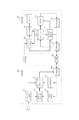
本実施形態の送信装置、受信装置の構成について、図1を用いて説明する。図1において、送信装置101と受信装置102が、伝送路109を介して接続されている。
<
The configuration of the transmission device and the reception device of this embodiment will be described with reference to FIG. In FIG. 1, a transmission device 101 and a
なお、送信装置101や受信装置102は、それぞれ単一のコンピュータ装置で実現してもよいし、必要に応じた複数のコンピュータ装置に各機能を分散して実現するようにしてもよい。複数のコンピュータ装置で構成される場合は、互いに通信可能なようにLocal Area Network(LAN)などで接続される。
Note that the transmission device 101 and the
また、本形態では、送信装置101が受信装置102に対してRTPプロトコルに基づいて動画データ(動画パケット)をストリーミング配信する例について説明するが、この例に限らない。例えば、動画パケットの代わりに、音声データを格納した音声パケットを送信するなど、他のメディアデータの送信に本発明を適用することが可能である。
In this embodiment, an example in which the transmission device 101 performs streaming distribution of moving image data (moving image packet) to the
送信装置101は、データパケット生成部103、誤り訂正符号化部104、冗長度制御部105、送信バッファ106、再送制御部107、送受信部108を含んで構成される。
The transmission apparatus 101 includes a data
データパケット生成部103は、外部から入力された動画の符号化データを、通信に適したサイズに分割し、通信するために必要なヘッダを付加してRTPのデータパケット(動画パケット)を生成する。
The data
誤り訂正符号化部104は、冗長度制御部105から指示される冗長度に従って、動画パケットからFECパケットを生成する。なお、FECパケットは、受信装置102が正常に受信しなかった動画パケットを受信装置102が復元するために用いる冗長データが格納された冗長パケットである。受信装置102は、正常に受信した他の動画パケットと、正常に受信したFECパケットを用いて、正常に受信できなかった動画パケットを復元できる。
The error
送信バッファ106は、データパケット生成部103により生成された動画パケット、及び、誤り訂正符号化部104により生成されたFECパケットを一時的に保管する。
The
送受信部108は、送信バッファ106に一時保管された動画パケットおよびFECパケットを、伝送路109を介して受信装置102に送信する。すなわち、送信装置101は、メディアデータ(動画パケット)を受信装置102に送信すると共に、受信装置102が正常に受信しなかったメディアデータを復元するための冗長データ(FECパケット)を送信する。送路109は各種ネットワークに代表される伝送路であり、本実施形態においては、動画パケットやFECパケットを通信するためのネットワークである。
The transmission / reception unit 108 transmits the moving image packet and the FEC packet temporarily stored in the
送受信部108は、伝送路109からパケットを受信する機能も備えている。送受信部108は、例えば受信装置102におけるパケットの受信状況に関する通知パケットや、受信装置102が正常に受信しなかった動画パケットの再送要求パケットを受信する。
The transmission / reception unit 108 also has a function of receiving a packet from the
再送制御部107は、送受信部108が受信した再送要求パケットに対応する動画パケットを、送受信部108に再送させる。再送要求パケットに対応する動画パケットは、送信バッファ106に記憶されている。
The retransmission control unit 107 causes the transmission / reception unit 108 to retransmit the moving image packet corresponding to the retransmission request packet received by the transmission / reception unit 108. The moving image packet corresponding to the retransmission request packet is stored in the
冗長度制御部105は、送受信部108が受信装置102から受信した通知パケットに基づいて、誤り訂正符号の冗長度を決定する。そして、冗長度制御部105は、誤り訂正符号化部104に決定した冗長度を通知する。なお、誤り訂正符号の冗長度とは、動画データのデータ量に対する冗長データのデータ量である。誤り訂正符号化部104は、冗長度制御部105により通知された冗長度に従って、動画パケットからFECパケットを生成する。通知パケットの詳細と、冗長度制御部105による冗長度の決定方法の詳細は後述する。
The redundancy control unit 105 determines the redundancy of the error correction code based on the notification packet received from the
受信装置102は送受信部110、受信バッファ111、受信状況解析部112、復元部113、再送要求部114、バッファ制御部115を含んで構成される。また、本形態の受信装置102は、再生処理部116、表示部117を含んでいる。
送受信部110は、送信装置101から送信される受信装置102宛てのパケットを伝送路109から受信する。また、送受信部110は、伝送路109に任意のパケットを送信する。
The
The transmission /
受信バッファ111は、送受信部110により受信された動画パケット、FECパケットを格納する。受信状況解析部112は、受信バッファ111に格納されたパケットのシーケンスンナンバーを監視することで、例えば伝送路109上の中継装置で廃棄されるなどして失われたパケットを識別する。シーケンスナンバーとは、RTPで送信される動画パケットおよびFECパケットごとに連番で付加される番号である。受信状況解析部112は、シーケンスナンバーの抜けを監視することで正常に受信できなかった動画パケットを特定する。受信状況解析部112は、正常に受信できなかった動画パケットのシーケンスナンバーを復元部113に通知する。
The reception buffer 111 stores moving image packets and FEC packets received by the transmission /
復元部113は、受信状況解析部112からの通知に応じて、正常に受信した動画パケットとFECパケットを利用して誤り訂正符号を復号することにより、正常に受信できなかった動画パケットを復元する。受信バッファ111は、復元部113により復元された動画パケットを格納する。また、復元部113は、FECパケットで復元できなかった動画パケットのシーケンスナンバーを再送要求部114に通知する。
In response to the notification from the reception status analysis unit 112, the restoration unit 113 restores the video packet that could not be normally received by decoding the error correction code using the video packet and the FEC packet that were normally received. . The reception buffer 111 stores the moving image packet restored by the restoration unit 113. Further, the restoration unit 113 notifies the
再送要求部114は、復元部113からの通知に応じて、FECパケットで復元できなかった動画パケットの再送要求パケットを生成し、送受信部110を介して送信装置101に送信する。
In response to the notification from the restoration unit 113, the
本形態の受信状況解析部112は、受信装置102におけるパケットの受信状況を示す通知パケット(受信レポート)を生成する。この受信レポートの送信は定期的に行われ、送信装置101の冗長度制御部105は、受信した受信レポートに応じて誤り訂正符号の冗長度を制御する。
The reception status analysis unit 112 according to the present exemplary embodiment generates a notification packet (reception report) indicating the reception status of the packet in the
バッファ制御部115は、受信装置102における動画データ(メディアデータ)の受信から再生処理開始までの時間に応じたバッファリング時間を入力する。また、バッファ制御部115は、受信バッファ111の動画パケットの格納状況を監視し、バッファリング時間に従って、再生処理部116へ復号処理の実行を指令する。
The buffer control unit 115 inputs a buffering time corresponding to the time from the reception of the moving image data (media data) in the receiving
再生処理部116は、バッファ制御部115からの指示に応じて、受信バッファ111に格納されている動画パケットから符号化された動画データを取り出して復号する。表示部117は、復号された動画データを表示装置に出力する。
In response to an instruction from the buffer control unit 115, the reproduction processing unit 116 extracts and decodes the encoded moving image data from the moving image packet stored in the reception buffer 111. The
本形態では、受信装置102でのパケットの受信状況に関する通知パケット(受信レポート)や、送信装置101でのパケットの送信状況に関する通知パケット(送信レポート)の通信プロトコルにRTCP(RTP Control Protocol)を用いる。RTCPは、RTPと同様にRFC3550で定義され、主にRTPでのデータ送受信の状況を送信側・受信側の双方で把握するために利用される。
In this embodiment, RTCP (RTP Control Protocol) is used as a communication protocol for a notification packet (reception report) regarding a packet reception status at the
RTCPのパケットとして、以下の5種類が定義されている。すなわち、受信レポート、送信レポート、ソース記述、メンバシップ管理、及びアプリケーション定義の5種類である。なお、受信レポートはReceiver Report(RR)、送信レポートはSender Report(SR)、ソース記述はSource Description(SDES)とも呼ばれる。また、メンバシップ管理はBYE、アプリケーション定義はApplication−Defined(APP)とも呼ばれる。 The following five types of RTCP packets are defined. That is, there are five types: reception report, transmission report, source description, membership management, and application definition. The reception report is also called Receiver Report (RR), the transmission report is also called Sender Report (SR), and the source description is also called Source Description (SDES). Membership management is also called BYE, and application definition is also called Application-Defined (APP).
本実施形態の受信装置102が、受信状況に関する通知パケットとして送信するRTCPの受信レポートの構成を図5に示す。
FIG. 5 shows the configuration of an RTCP reception report that the receiving
図5に示すように、受信レポートは、RTCPヘッダ501と、受信レポートブロック502と、プロファイル依存拡張503で構成される。受信レポートブロック502はRC(reception report count)504に示される数だけ存在する。
As shown in FIG. 5, the reception report includes an RTCP header 501, a
次に受信レポートブロック502の構成について説明する。 Next, the configuration of the reception report block 502 will be described.
瞬時廃棄率(Fraction Lost)505は、最後に受信レポートを生成してから、次の受信レポートを生成するまでに損失したRTPパケットの割合を示す値を含むものである。 The instantaneous loss rate (Fraction Loss) 505 includes a value indicating the ratio of RTP packets lost from the last generation of a reception report to the generation of the next reception report.
累積パケット廃棄率(cumulative number of packets lost)506は、通信を開始してから受信レポート生成までに損失したRTPパケットの総数を含む値が格納される。 A cumulative packet of packets lost 506 stores a value including the total number of RTP packets lost from the start of communication until reception report generation.
パケット間隔ジッタ(interarrival jitter)507は、RTPパケットの受信時刻の揺らぎを統計的な計算により処理した予測値が含まれる。 The packet interval jitter 507 includes a predicted value obtained by processing fluctuation of the reception time of the RTP packet by statistical calculation.
LSR(last SR timestamp)508は、受信装置102が最後に受信した送信レポートから取得した64ビットで構成されるNTP(Network Time Protocol)タイムスタンプの中間32ビットを含む。すなわち、LSR508には、受信装置102が最後に受信した送信レポートを送信装置101が送信した時刻が格納されている。
The LSR (last SR time stamp) 508 includes the middle 32 bits of an NTP (Network Time Protocol) time stamp composed of 64 bits acquired from the transmission report last received by the receiving
DLSR(Delay since last SR)509は、受信装置102が最後に受信した送信レポートの受信時刻から、受信レポートを送信するまでの遅延時間を含む値が格納される。
尚、送信レポート(SR)は、前述した通りRTCPパケットのタイプの一つであり、主に送信状況を通知する為、送信側から受信側に配信される。
A DLSR (Delay Since Last SR) 509 stores a value including a delay time from the reception time of the transmission report last received by the receiving
The transmission report (SR) is one of the types of RTCP packets as described above, and is distributed from the transmission side to the reception side mainly to notify the transmission status.
本実施形態の受信状況解析部112は、バッファリング時間を受信レポートの拡張領域であるプロファイル依存拡張503に格納する。バッファリング時間は、バッファ制御部115から通知される。このバッファリング時間は、ユーザによって設定されても良いし、例えばアプリケーションによって決定されても良い。送信装置101の冗長度制御部105は、上記のような受信レポートを含む通知パケットの受信に応じて、冗長度を制御する。 The reception status analysis unit 112 of the present embodiment stores the buffering time in the profile dependent extension 503 that is an extension area of the reception report. The buffering time is notified from the buffer control unit 115. This buffering time may be set by the user or may be determined by the application, for example. The redundancy control unit 105 of the transmission device 101 controls the redundancy according to reception of the notification packet including the reception report as described above.
次に、冗長度制御部105におけるFEC冗長度の制御方法について説明する。 Next, a method for controlling the FEC redundancy in the redundancy control unit 105 will be described.
本形態の冗長度制御部105は、受信レポートに含まれる瞬時廃棄率505と、LSR508と、DLSR509に格納された値と、プロファイル依存拡張503に格納されたバッファリング時間を利用して、冗長度を決定する。 The redundancy control unit 105 according to the present embodiment uses the instantaneous discard rate 505, the LSR 508, the value stored in the DLSR 509, and the buffering time stored in the profile dependent extension 503 included in the reception report to determine the redundancy. To decide.
冗長度制御部105は、その情報を含む通知パケット(受信レポート)を受信した時刻の情報を送受信部108から受け取る。この受信時刻をRT(rtcp)と表記すると、送信装置101と受信装置102間の往復遅延時間RTT(Round Trip Time)は次の計算式で表せる。
RTT = RT(rtcp) − LSR − DLSR
RTTは、送信装置101と受信装置102との間をパケットが往復するのに要する時間である。
The redundancy control unit 105 receives information on the time when the notification packet (reception report) including the information is received from the transmission / reception unit 108. When this reception time is expressed as RT (rtcp), the round trip time RTT (Round Trip Time) between the transmission apparatus 101 and the
RTT = RT (rtcp) −LSR−DLSR
RTT is the time required for a packet to reciprocate between the transmission apparatus 101 and the
再送するパケットが間に合うか否かを判断するには、受信装置102でのバッファリング時間からRTTを減算した時間が目安となる。そこで、この時間を再送猶予時間と呼ぶことにすると、次の計算式で示すことができる。
再送猶予時間 = バッファリング時間 − RTT
すなわち、冗長度制御部105は、バッファリング時間から伝達時間(RTT)を差し引いて再送猶予時間(猶予時間)を取得する。
In order to determine whether or not the packet to be retransmitted is in time, a time obtained by subtracting RTT from the buffering time in the receiving
Retransmission grace time = buffering time-RTT
That is, the redundancy control unit 105 subtracts the transmission time (RTT) from the buffering time to obtain the retransmission grace time (grace time).
この再送猶予時間が大きいほど、再送パケットが受信装置102の再生処理に間に合う確率は高くなる。従って、パケットの廃棄率が同程度の伝送路であれば、再送猶予時間が短いほどFEC冗長度を高める必要がある。逆に再送猶予時間が長いほど、再送パケットによる補完が期待できるので、FEC冗長度を低くすることができる。
The longer this retransmission grace time is, the higher the probability that a retransmission packet will be in time for the reproduction processing of the receiving
本実施形態では、FEC冗長度の決定に冗長度クラスという概念を用いる。冗長度クラスとは、再送猶予時間によって一意に決定されるクラスであり、例えば図2のように設定する。 In the present embodiment, the concept of redundancy class is used to determine the FEC redundancy. The redundancy class is a class uniquely determined by the retransmission grace time, and is set as shown in FIG. 2, for example.
本形態の冗長度制御部105は、受信レポートから求めた再送猶予時間に応じて、冗長度クラスを設定する。図2において、例えば、再送猶予時間(T)が閾値Th(b)と閾値Th(c)の間の場合、冗長度クラスはBとなる。 The redundancy control unit 105 of this embodiment sets a redundancy class according to the retransmission grace time obtained from the reception report. In FIG. 2, for example, when the retransmission grace time (T) is between the threshold Th (b) and the threshold Th (c), the redundancy class is B.
また、本実施形態の冗長度制御部105は、冗長度クラスとパケット廃棄率に基づいてFEC冗長度を決定する。具体的な例を図3に示す。 In addition, the redundancy control unit 105 of the present embodiment determines the FEC redundancy based on the redundancy class and the packet discard rate. A specific example is shown in FIG.
図3において、グラフの横軸はパケット廃棄率であり、縦軸はFEC冗長度である。図3に示すように、各冗長度クラスにおいて、パケット廃棄率が高いほど、FEC冗長度が高くなる。すなわち、冗長度制御部105は、受信装置102が正常に受信しなかったエラーデータ量に応じたエラー情報(瞬時廃棄率505)を取得する。そして、冗長度制御部105は、冗長度クラスBに対応する受信装置において、例えばパケット廃棄率Eに応じたエラー情報が取得された場合、パケット廃棄率Eよりもエラーデータ量が多いエラー情報が取得された場合よりも、FEC冗長度を低くする。
In FIG. 3, the horizontal axis of the graph is the packet discard rate, and the vertical axis is the FEC redundancy. As shown in FIG. 3, in each redundancy class, the higher the packet discard rate, the higher the FEC redundancy. In other words, the redundancy control unit 105 acquires error information (instantaneous discard rate 505) corresponding to the amount of error data that the receiving
また、図3に示すように、パケット廃棄率が同じでも、冗長度クラスによってFEC冗長度が異なる。例えば、冗長度クラスB(302)の場合、パケット廃棄率がEの時に設定されるFEC冗長度はRbとなり、再送猶予時間が短い冗長度クラスA(301)よりもFEC冗長度は低くなる。また、逆に再送猶予時間が長い冗長度クラスC(303)よりもFEC冗長度は高くなる。 As shown in FIG. 3, even if the packet discard rate is the same, the FEC redundancy differs depending on the redundancy class. For example, in the case of the redundancy class B (302), the FEC redundancy set when the packet discard rate is E is Rb, and the FEC redundancy is lower than that of the redundancy class A (301) with a short retransmission grace period. Conversely, the FEC redundancy is higher than that of the redundancy class C (303) having a long retransmission grace time.
すなわち、冗長度制御部105は、冗長度クラスBに対応する第1の猶予時間が取得された場合、冗長度クラスAに対応する第2の猶予時間が取得された場合よりも、FEC冗長度(メディアデータのデータ量に対する冗長データのデータ量)を少なくする。 That is, when the first grace time corresponding to the redundancy class B is acquired, the redundancy control unit 105 determines that the FEC redundancy is higher than when the second grace time corresponding to the redundancy class A is acquired. Reduce the amount of redundant data relative to the amount of media data.
このように冗長度制御部105は、受信装置102のバッファリング時間とRTTとパケット廃棄率などの通信状況を受信レポートから取得し、FEC冗長度を制御する。このようにすることで、受信装置102の状況により適合した冗長度の制御を実現することができる。
As described above, the redundancy control unit 105 acquires the communication status such as the buffering time, RTT, and packet discard rate of the
冗長度制御部105によるFEC冗長度制御のもう一つの例を、図7を用いて説明する。この例において、冗長度制御部105は、動画データのフレームタイプに応じて冗長度を変更する。 Another example of FEC redundancy control by the redundancy control unit 105 will be described with reference to FIG. In this example, the redundancy control unit 105 changes the redundancy according to the frame type of the moving image data.
本実施形態では、送信装置101のデータパケット生成部103に符号化データが入力されると説明したが、動画データの符号化方法には、MPEG−2やMPEG−4、H.264(MPEG−4 AVC)などの符号化方法が広く使われている。例えばMPEG−4の場合、符号化の方法によって主要な3つのフレームタイプがあることが知られている。
In the present embodiment, it has been described that the encoded data is input to the data
1つ目のタイプは、そのフレームのデータのみで復号可能な符号化方法でIフレームと呼ばれている。2つ目のタイプは、時間的に前のフレームを参照してその差分情報を基に符号化したもので、Pフレームと呼ばれている。3つ目のタイプは、時間的に前後のフレームを参照して、その差分情報を基に符号化したもので、Bフレームと呼ばれる。 The first type is an I-frame which is an encoding method that can be decoded only with the data of the frame. The second type refers to a temporally previous frame and is encoded based on the difference information, and is called a P frame. The third type refers to frames that are temporally related and are encoded based on the difference information, and is called a B frame.
再送猶予時間によってクラス分けされた冗長度クラス毎に、FECパケットを生成するフレームタイプを決める方法を図7を用いて説明する。 A method of determining the frame type for generating the FEC packet for each redundancy class classified by the retransmission grace time will be described with reference to FIG.
例えば、再送猶予時間が短い冗長度クラスAでは、すべてのタイプのフレームのFECパケットを生成する。また、冗長度クラスBでは、IフレームとPフレームに対してFECパケットを生成しBフレームの動画パケットを復元するためのFECパケットを生成しない。さらに、冗長度クラスCでは、IフレームのFECパケットを生成し、PフレームとBフレームのFECパケットを生成しない。再送猶予時間が十分に長い冗長度クラスDでは、すべてのタイプのフレームのFECパケットを生成しない。 For example, in the redundancy class A with a short retransmission grace time, FEC packets of all types of frames are generated. In the redundancy class B, FEC packets are generated for the I frame and the P frame, and an FEC packet for restoring the moving image packet of the B frame is not generated. Further, in the redundancy class C, an FEC packet of I frame is generated, and an FEC packet of P frame and B frame is not generated. In the redundancy class D having a sufficiently long retransmission grace time, FEC packets of all types of frames are not generated.
すなわち、冗長度制御部105は、冗長度クラスAに対応する再送猶予時間が取得された場合、インターフレーム(P、Bフレーム)のFECデータとイントラフレーム(Iフレーム)のFECデータを生成することを決定する。また、冗長度制御部105は、冗長度クラスCに対応する再送猶予時間が取得された場合、インターフレームのFECデータを生成せず、イントラフレームのFECデータを生成することを決定する。 That is, when the retransmission grace time corresponding to the redundancy class A is acquired, the redundancy control unit 105 generates FEC data for inter frames (P, B frames) and FEC data for intra frames (I frames). To decide. In addition, when the retransmission grace time corresponding to the redundancy class C is acquired, the redundancy control unit 105 determines to generate the intra-frame FEC data without generating the inter-frame FEC data.
なお、本形態では、冗長度クラスを4つに分類しているが、例えば、より多くのクラスに分類しても良い。また、フレームタイプによって異なる冗長度を設定するようにしても良い。 In this embodiment, the redundancy class is classified into four, but may be classified into more classes, for example. Different redundancy may be set depending on the frame type.
次に、本形態の送信装置101の処理について図4の処理フロー図を用いて説明する。
なお、本形態の送信装置101は、図4のフロー図に対応する処理プログラムを格納したROMから、送信装置101のCPUが当該プログラムをRAMに読み出して実行することにより実現される。
Next, processing of the transmission apparatus 101 according to the present embodiment will be described with reference to the processing flowchart of FIG.
The transmission apparatus 101 according to the present embodiment is realized by the CPU of the transmission apparatus 101 reading the program from the ROM storing the processing program corresponding to the flowchart of FIG. 4 and executing the program.
図4において、まず受信装置102との間で、通信するためのセッションを確立する(ステップS401)。なお、RTPやRTCP等のプロトコルにより通信するためには、RTSP(Real Time Streaming Protocol)やSIP(Session Initiation Protocol)などを使用してセッションを制御する必要がある。本実施形態においては、主に送信と受信の2つの役割の通信であるので、この様な用途のセッション制御にはRTSPが適している。 In FIG. 4, first, a session for communication is established with the receiving apparatus 102 (step S401). In order to communicate using a protocol such as RTP or RTCP, it is necessary to control the session using RTSP (Real Time Streaming Protocol), SIP (Session Initiation Protocol), or the like. In the present embodiment, since communication is mainly performed in two roles, transmission and reception, RTSP is suitable for session control for such applications.
次に、冗長度制御部105は、FEC冗長度の初期設定を行う(ステップS402)。 Next, the redundancy control unit 105 performs initial setting of the FEC redundancy (step S402).
通信開始前は、通信経路の状況がわからないので、FECの冗長データによって帯域を無駄に使用しないように、FEC冗長度を低めに設定しても良い。或いは、冗長度クラスとパケット廃棄率を制御範囲の中間程度の値に設定しても良い。或いは、既存のセッションに新たにセッションを追加する場合は、既存のセッションのFEC冗長度に合わせても良い。 Since the state of the communication path is unknown before the start of communication, the FEC redundancy may be set low so that the bandwidth is not wasted using FEC redundant data. Alternatively, the redundancy class and the packet discard rate may be set to a value approximately in the middle of the control range. Alternatively, when a new session is added to the existing session, it may be matched with the FEC redundancy of the existing session.
FEC冗長度の初期設定が完了したら、送受信部108は、動画パケット及びFECパケットの送信を開始する(ステップS403)。 When the initial setting of the FEC redundancy is completed, the transmission / reception unit 108 starts transmission of the moving image packet and the FEC packet (step S403).
送受信部108は、ステップS403で開始された通信が終了したか否かを判定する(ステップS404)。通信が終了したと判定された場合、送受信部108は、動画パケット及びFECパケットの送信を終了し(ステップS407)、セッションを削除する(ステップS408)。ステップS404で通信が終了していないと判定された場合はステップS405に進む。 The transmission / reception unit 108 determines whether or not the communication started in step S403 has ended (step S404). If it is determined that the communication has ended, the transmission / reception unit 108 ends the transmission of the moving image packet and the FEC packet (step S407), and deletes the session (step S408). If it is determined in step S404 that communication has not ended, the process proceeds to step S405.
動画パケットの通信中は、定期的に、RTCPの送信レポートと受信レポートが相互に送られる。本実施形態の冗長度制御部105は、RTCPの受信レポートを用いて、バッファリング時間とRTTとパケット廃棄率を取得する(ステップS405)。すなわち、冗長度制御部105は、ステップS405(取得手順)で、受信装置102における動画パケット(メディアデータ)の受信から再生処理開始までの時間に応じたバッファリング時間を取得する。また、冗長度制御部105は、送信装置101と受信装置102との間におけるデータの伝達時間(RTT)を取得する。
During the communication of moving image packets, RTCP transmission reports and reception reports are sent to each other periodically. The redundancy control unit 105 of the present embodiment acquires the buffering time, the RTT, and the packet discard rate using the RTCP reception report (step S405). That is, in step S405 (acquisition procedure), the redundancy control unit 105 acquires a buffering time corresponding to the time from the reception of the moving image packet (media data) in the receiving
そして、冗長度制御部105は、バッファリング時間とRTTとを用いて再送猶予時間を求めてFECの冗長度クラスを設定する(ステップS406)。そして、冗長度制御部105は、冗長度クラスとパケット廃棄率に応じてFEC冗長度を制御する。 Then, the redundancy control unit 105 obtains the retransmission grace time using the buffering time and the RTT, and sets the FEC redundancy class (step S406). Then, the redundancy control unit 105 controls the FEC redundancy according to the redundancy class and the packet discard rate.
すなわち、冗長度制御部105は、ステップS406(決定手順)で、バッファリング時間と伝達時間(RTT)に基づいて動画データ(メディアデータ)のデータ量に対するFECデータ(冗長データ)のデータ量を決定する。 That is, the redundancy control unit 105 determines the data amount of the FEC data (redundant data) with respect to the data amount of the moving image data (media data) based on the buffering time and the transmission time (RTT) in step S406 (decision procedure). To do.
そして、誤り訂正符号化部104は、冗長度制御部105の決定に応じてFECパケット(冗長データ)を生成し(生成手順)、送受信部108から受信装置102に送信する。
本形態の冗長度制御部105は、RTCPの受信レポートを受信する度にステップS405とS406の処理を行う。
Then, the error
The redundancy control unit 105 of the present embodiment performs the processes of steps S405 and S406 every time an RTCP reception report is received.
例えばユーザの操作によって受信装置102においてバッファリング時間が変更になった場合、ステップS405で、冗長度制御部105は受信装置102からの通知パケット(受信レポート)に応じて変更後のバッファリング時間を取得する。そして、冗長度制御部105は、ステップS406で、RTT(伝達時間)と、変更後のバッファリング時間とに基づいて、FEC冗長度(動画データに対するFECデータのデータ量)を変更する。
For example, when the buffering time is changed in the receiving
なお、受信装置102においてFECを用いても復元できない動画パケットがあった場合には、再送要求パケットが送信装置101へ送信される。そして、送信装置101の再送制御部107は、再送要求された動画パケットを再送する。
If there is a moving image packet that cannot be restored using FEC in the receiving
ここまでに説明したように、本実施形態の送信装置101は、受信装置側で設定されるバッファリング時間と、通信状況に応じたRTTから、再送猶予時間を算出する。そして、送信装置101は、算出された再送猶予時間と、パケット廃棄率(瞬時廃棄率505)に基づいてFEC冗長度を設定する。このようにすることで、効率の良いハイブリッドARQを実現できる。 As described so far, the transmission apparatus 101 according to the present embodiment calculates the retransmission grace time from the buffering time set on the reception apparatus side and the RTT corresponding to the communication status. The transmission apparatus 101 sets the FEC redundancy based on the calculated retransmission grace time and the packet discard rate (instantaneous discard rate 505). By doing in this way, efficient hybrid ARQ is realizable.
本発明を実際の通信経路に適用した場合の例について、図6を用いて説明する。 An example in which the present invention is applied to an actual communication path will be described with reference to FIG.
図6において、横軸は再送猶予時間であり、Client1〜3は、各々の再送猶予時間に基づいて位置付けされている。つまり、Client1は、Client1〜3のうちで最も再送猶予時間が長いクライアントであり、Client2は、最も再送猶予時間が短いクライアントである。
In FIG. 6, the horizontal axis is a retransmission grace time, and
図6に示すように、例えばClient1は送信装置と同じイントラネット内に位置しており、RTTは20msである。また、Client1で設定されているバッファリング時間は400msである。従って、Client1の再送猶予時間は380msとなる。本形態では、Client1は冗長度クラスDに設定される。冗長度クラスDは再送猶予時間が長いため、仮に動画パケットの欠落が発生しても再送パケットが受信装置における再生処理に間に合う可能性が高い。このため、送信装置101は、冗長度クラスDに設定した受信装置に対しては、FEC冗長度を低めに設定する(もしくはFECパケットを送信しない)。
As shown in FIG. 6, for example, Client1 is located in the same intranet as the transmission apparatus, and RTT is 20 ms. Further, the buffering time set in
一方、Client2は、送信装置と同じ国に存在するが、Client1よりも地理的に離れて位置しており、RTTは80msである。また、Client2で設定されているバッファリング時間は100msである。従って、Client2の再送猶予時間は20msとなる。本形態では、Client2は冗長度クラスAに設定される。冗長度クラスAは再送猶予時間が短いため、動画パケットが欠落すると再送パケットが受信装置における再生処理に間に合わない可能性が高い。このため、送信装置101は、冗長度クラスAに設定した受信装置に対しては、FEC冗長度を高めに設定する。 On the other hand, Client2 exists in the same country as the transmission device, but is located geographically farther than Client1, and RTT is 80 ms. Further, the buffering time set in Client 2 is 100 ms. Accordingly, the retransmission grace time for Client 2 is 20 ms. In this embodiment, Client2 is set to redundancy class A. Since the redundancy class A has a short retransmission grace time, if a moving image packet is lost, there is a high possibility that the retransmission packet will not be in time for the reproduction processing in the receiving apparatus. For this reason, the transmission apparatus 101 sets the FEC redundancy higher for the reception apparatus set to the redundancy class A.
Client3は、Client1〜3の中で、地理的に送信装置から最も離れた位置に存在しており、RTTは420msである。また、Client3で設されているバッファリング時間は600msである。従って、Client3の再送猶予時間は180msとなる。本形態では、Client3は冗長度クラスCに設定される。冗長度クラスCは冗長度クラスAやBよりも再送猶予時間が長いため、冗長度制御部105は、冗長度クラスAやBの受信装置よりもFEC冗長度を低くする。また、冗長度クラスCは冗長度クラスDよりも再送猶予時間が短いため、冗長度制御部105は、冗長度クラスDの受信装置よりもFEC冗長度を高くする。
Client 3 is geographically located farthest from the transmission device among
すなわち、送信装置からの距離は、Client1、2、3の順に近いが、バッファリング時間を考慮した再送猶予時間においては、Client1、3、2の順に再送パケットが動画の再生に間に合う可能性が高くなる。
That is, the distance from the transmission device is close to
以上説明したように、本形態の冗長度制御部105は、バッファリング時間と伝達時間を考慮することにより、再送パケットが間に合う可能性に合わせてFEC冗長度を制御する。これにより、エラー訂正用の冗長データの送信量をより適切に制御できるようになる。 As described above, the redundancy control unit 105 according to the present embodiment controls the FEC redundancy in accordance with the possibility that the retransmission packet is in time by considering the buffering time and the transmission time. This makes it possible to more appropriately control the transmission amount of redundant data for error correction.
<実施形態2>
実施形態1では、バッファリング時間とRTTに基づいてFEC冗長度を決定していたが、例えばインターネットなどのベストエフォートの通信回線では、RTTの値が揺らぐ、所謂ジッタの影響を受けることになる。
<Embodiment 2>
In the first embodiment, the FEC redundancy is determined based on the buffering time and the RTT. However, in a best-effort communication line such as the Internet, for example, the RTT value fluctuates and is affected by so-called jitter.
つまり、ジッタが大きいということは、動画パケットごとの伝達時間の差が大きい、すなわち、ばらついていることを示している。ジッタが大きい場合、短い伝達時間で到達する動画パケットについては特に問題ないが、伝達時間が長くかかってしまう動画パケットについては、再送猶予時間が予想より短くなり、再送パケットが間に合わなくなる可能性がある。 That is, a large jitter indicates that the difference in transmission time for each moving image packet is large, that is, varies. If the jitter is large, there is no problem for video packets that arrive in a short transmission time, but for video packets that take a long transmission time, the resend grace time may be shorter than expected and the retransmission packets may not be in time. .
そこで、本実施形態では、実施形態1の方法で求めた再送猶予時間に、更にジッタの値を考慮して、FEC冗長度を制御する方法について説明する。 Therefore, in the present embodiment, a method for controlling the FEC redundancy in consideration of the jitter value in the retransmission grace time obtained by the method of the first embodiment will be described.
具体的には、本形態の冗長度制御部105は、図5に示す受信レポートのパケット間隔ジッタ507から、通信回線のジッタを取得する。すなわち、冗長度制御部105は、送信装置101が送信した動画パケットの受信装置102による受信時刻のばらつきに応じたジッタ情報を取得する。そして、冗長度制御部105は、再送猶予時間が同じ場合、ばらつきが大きいジッタ情報が取得された場合のほうがFEC冗長度が低くなるようにメディアデータ(動画データ)のデータ量に対するFECデータのデータ量を決定する。
Specifically, the redundancy control unit 105 according to the present embodiment acquires the communication line jitter from the packet interval jitter 507 of the reception report shown in FIG. That is, the redundancy control unit 105 acquires jitter information according to the variation in the reception time of the moving image packet transmitted by the transmission device 101 by the
パケット間隔ジッタ507は、RTPパケットのインターバル時間を統計的な手法により算出した分散値であり、パケットの到着間隔の送信時と受信時の差の平均偏差として定義されている。 The packet interval jitter 507 is a variance value obtained by calculating the interval time of the RTP packet by a statistical method, and is defined as an average deviation of the difference between the packet arrival interval at the time of transmission and at the time of reception.
つまり、パケット間隔ジッタ507に格納された値が大きいほど、パケットの到着間隔が変動する可能性が大きくなる。そこで、本形態の冗長度制御部105は、ジッタの値が大きいほど、再送猶予時間を短く見積もる。 That is, the larger the value stored in the packet interval jitter 507, the greater the possibility that the packet arrival interval will fluctuate. Therefore, the redundancy control unit 105 of the present embodiment estimates the retransmission grace time as the jitter value increases.
ただし、この方法に限らず、例えば、実施形態1で説明したような再送猶予時間をセッションごとに算出し、同等なセッションが複数あった場合に、ジッタの大きさによってFECの冗長度を変更しても良い。具体的には、同等の再送猶予時間であっても、ジッタが大きいセッションほどFECの冗長度を高く設定することで、伝送遅延が大きいときに廃棄されたパケットをFECパケットで復元できる。 However, not limited to this method, for example, the retransmission grace time as described in the first embodiment is calculated for each session, and when there are multiple equivalent sessions, the FEC redundancy is changed depending on the magnitude of jitter. May be. Specifically, even if the retransmission grace time is the same, by setting the FEC redundancy to be higher for a session with a larger jitter, a packet discarded when the transmission delay is large can be restored with the FEC packet.
例えば、送信装置が複数の受信装置にそれぞれ異なる動画データを送信している場合に、実施形態1の方法で各受信装置に対してそれぞれ算出した再送猶予時間が、すべて冗長度クラスAに対応する場合、FECパケットの生成が間に合わなくなる恐れがある。このような場合、冗長度制御部105は、ジッタが大きいセッションについては冗長度クラスAに対応させ、ジッタが比較的小さいセッションについては冗長度クラスBやCなどに対応させる。このようにすることで、再送パケットが間に合わなくなる可能性が高いセッションについてより多くのFECパケットを送信できる。 For example, when the transmitting apparatus transmits different moving image data to a plurality of receiving apparatuses, all of the retransmission grace times calculated for each receiving apparatus by the method of the first embodiment correspond to the redundancy class A. In such a case, there is a possibility that generation of the FEC packet may not be in time. In such a case, the redundancy control unit 105 causes a session with a large jitter to correspond to the redundancy class A, and associates a session with a relatively small jitter to the redundancy classes B and C. In this way, more FEC packets can be transmitted for a session that is likely to miss the retransmission packet in time.
なお、冗長度クラスの設定や冗長度の制御を行う方法は、本形態の方法に限らず、例えば、係数や多項式を用いて算出するようにしても良い。 Note that the method of setting the redundancy class and controlling the redundancy is not limited to the method of the present embodiment, and may be calculated using, for example, a coefficient or a polynomial.
<その他の実施形態>
また、本発明は、以下の処理を実行することによっても実現される。即ち、上述した実施形態の機能を実現するソフトウェア(プログラム)を、ネットワーク又は各種記憶媒体を介してシステム或いは装置に供給し、そのシステム或いは装置のコンピュータ(またはCPUやMPU等)がプログラムを読み出して実行する処理である。
<Other embodiments>
The present invention can also be realized by executing the following processing. That is, software (program) that realizes the functions of the above-described embodiments is supplied to a system or apparatus via a network or various storage media, and a computer (or CPU, MPU, or the like) of the system or apparatus reads the program. It is a process to be executed.
Claims (10)
受信装置におけるメディアデータの受信から再生処理開始までの時間に応じたバッファリング時間を取得すると共に、前記送信装置と前記受信装置との間におけるデータの伝達時間を取得する取得手段と、
前記バッファリング時間と前記伝達時間に基づいて前記メディアデータのデータ量に対する前記冗長データのデータ量を決定する決定手段と、
前記決定手段の決定に応じて冗長データを生成する生成手段と
を有することを特徴とする送信装置。 A transmitting device that transmits media data to a receiving device and transmits redundant data for restoring the media data that the receiving device did not normally receive,
An acquisition means for acquiring a buffering time corresponding to a time from reception of media data to a start of reproduction processing in the reception device, and acquiring a transmission time of data between the transmission device and the reception device;
Determining means for determining a data amount of the redundant data with respect to a data amount of the media data based on the buffering time and the transmission time;
And a generation unit configured to generate redundant data in response to the determination by the determination unit.
前記決定手段は、第1の猶予時間が取得された場合、前記第1の猶予時間より短い第2の猶予時間が取得された場合よりも、前記メディアデータのデータ量に対する冗長データのデータ量を少なくすることを特徴とする請求項1記載の送信装置。 The acquisition means acquires a grace time by subtracting the transmission time from the buffering time,
When the first grace time is acquired, the determining means determines the amount of redundant data relative to the data amount of the media data more than when the second grace time shorter than the first grace time is acquired. 2. The transmission apparatus according to claim 1, wherein the number is reduced.
前記決定手段は、
前記第1の猶予時間が取得された場合、前記動画データのフレームのうち他のフレームを参照せずに復号可能なインターフレームの冗長データと、他のフレームを参照せずに復号可能なイントラフレームの冗長データを生成することを決定し、
前記第1の猶予時間より短い前記第2の猶予時間が取得された場合、前記インターフレームの冗長データを生成せず、前記イントラフレームの冗長データを生成することを決定することを特徴とする請求項2に記載の送信装置。 The media data is encoded video data,
The determining means includes
When the first grace period is acquired, inter-frame redundant data that can be decoded without referring to other frames among the frames of the moving image data, and intra-frame that can be decoded without referring to other frames Decide to generate redundant data,
When the second grace time shorter than the first grace time is acquired, it is determined not to generate redundant data of the inter frame but to generate redundant data of the intra frame. Item 3. The transmission device according to Item 2.
前記決定手段は、
第1のエラーデータ量に応じた第1のエラー情報と、前記第1の猶予時間が取得された場合、
前記第1のエラーデータ量よりも多い第2のエラーデータ量に応じた第2のエラー情報と、前記第1の猶予時間が取得された場合よりも、
前記メディアデータのデータ量に対する冗長データのデータ量が少なくなるように、前記メディアデータのデータ量に対する冗長データのデータ量を決定することを特徴とする請求項2記載の送信装置。 The acquisition means acquires error information according to the amount of error data that the receiving device did not normally receive,
The determining means includes
When the first error information corresponding to the first error data amount and the first grace time are acquired,
Than the case where the second error information corresponding to the second error data amount larger than the first error data amount and the first grace time are acquired,
3. The transmission apparatus according to claim 2, wherein the amount of redundant data relative to the amount of media data is determined so that the amount of redundant data relative to the amount of media data decreases.
前記決定手段は、
第1のばらつきに応じた第1のジッタ情報と、前記第1の猶予時間が取得された場合、
前記第1のばらつきよりもばらつきが大きい第2のばらつきに応じた第2のジッタ情報と、前記第1の猶予時間が取得された場合よりも、
前記メディアデータのデータ量に対する冗長データのデータ量が少なくなるように、前記メディアデータのデータ量に対する冗長データのデータ量を決定することを特徴とする請求項2又は4記載の送信装置。 The acquisition means acquires jitter information according to variations in reception time by a receiving device of media data packets transmitted by the transmitting device;
The determining means includes
When the first jitter information corresponding to the first variation and the first grace period are acquired,
Than when the second jitter information corresponding to the second variation having a larger variation than the first variation and the first grace time are acquired,
5. The transmission apparatus according to claim 2, wherein the amount of redundant data relative to the amount of media data is determined so that the amount of redundant data relative to the amount of media data decreases.
前記決定手段は、前記伝達時間と、前記変更された後のバッファリング時間とに基づいて、前記メディアデータのデータ量に対する冗長データのデータ量を変更することを特徴とする請求項1又は2記載の送信装置。 The acquisition means acquires a buffering time after being changed in the receiving device in response to a notification from the receiving device,
3. The determination unit according to claim 1, wherein the determining unit changes a data amount of redundant data with respect to a data amount of the media data based on the transmission time and the buffering time after the change. Transmitter.
受信装置におけるメディアデータの受信から再生処理開始までの時間に応じたバッファリング時間を取得すると共に、前記送信装置と前記受信装置との間におけるデータの伝達時間を取得する取得工程と、
前記バッファリング時間と前記伝達時間に基づいて前記メディアデータのデータ量に対する前記冗長データのデータ量を決定する決定工程と、
前記決定工程の決定に応じて冗長データを生成する生成工程と
を有することを特徴とする送信方法。 A transmission method performed by a transmitting device that transmits media data to a receiving device and transmits redundant data for restoring the media data that the receiving device did not normally receive,
An acquisition step of acquiring a buffering time according to a time from reception of media data to a start of reproduction processing in the reception device, and acquiring a transmission time of data between the transmission device and the reception device;
Determining a data amount of the redundant data with respect to a data amount of the media data based on the buffering time and the transmission time;
And a generation step of generating redundant data according to the determination in the determination step.
前記決定工程では、第1の猶予時間が取得された場合、前記第1の猶予時間より短い第2の猶予時間が取得された場合よりも、前記メディアデータのデータ量に対する冗長データのデータ量を少なくすることを特徴とする請求項7記載の送信方法。In the determining step, when the first grace time is acquired, the amount of redundant data relative to the data amount of the media data is set more than when the second grace time shorter than the first grace time is acquired. The transmission method according to claim 7, wherein the number is reduced.
前記決定工程では、In the determination step,
前記第1の猶予時間が取得された場合、前記動画データのフレームのうち他のフレームを参照せずに復号可能なインターフレームの冗長データと、他のフレームを参照せずに復号可能なイントラフレームの冗長データを生成することを決定し、When the first grace period is acquired, inter-frame redundant data that can be decoded without referring to other frames among the frames of the moving image data, and intra-frame that can be decoded without referring to other frames Decide to generate redundant data,
前記第1の猶予時間より短い前記第2の猶予時間が取得された場合、前記インターフレームの冗長データを生成せず、前記イントラフレームの冗長データを生成することを決定することを特徴とする請求項8に記載の送信方法。When the second grace time shorter than the first grace time is acquired, it is determined not to generate redundant data of the inter frame but to generate redundant data of the intra frame. Item 9. The transmission method according to Item 8.
受信装置におけるメディアデータの受信から再生処理開始までの時間に応じたバッファリング時間を取得すると共に、前記送信装置と受信装置との間におけるデータの伝達時間を取得する取得手順と、
前記バッファリング時間と前記伝達時間に基づいて前記メディアデータのデータ量に対する前記冗長データのデータ量を決定する決定手順と、
前記決定手順の決定に応じて冗長データを生成する生成手順と
を実行させることを特徴とするプログラム。 A computer that transmits media data to a receiving device and transmits redundant data for restoring the media data that the receiving device did not normally receive,
An acquisition procedure for acquiring a buffering time according to a time from reception of media data to a start of reproduction processing in the receiving device, and acquiring a data transmission time between the transmitting device and the receiving device
A determination procedure for determining a data amount of the redundant data with respect to a data amount of the media data based on the buffering time and the transmission time;
A program for executing a generation procedure for generating redundant data in response to determination of the determination procedure.
Priority Applications (1)
| Application Number | Priority Date | Filing Date | Title |
|---|---|---|---|
| JP2010075664A JP5523163B2 (en) | 2010-03-29 | 2010-03-29 | Transmission device, transmission method, and program |
Applications Claiming Priority (1)
| Application Number | Priority Date | Filing Date | Title |
|---|---|---|---|
| JP2010075664A JP5523163B2 (en) | 2010-03-29 | 2010-03-29 | Transmission device, transmission method, and program |
Publications (3)
| Publication Number | Publication Date |
|---|---|
| JP2011211390A JP2011211390A (en) | 2011-10-20 |
| JP2011211390A5 JP2011211390A5 (en) | 2013-05-16 |
| JP5523163B2 true JP5523163B2 (en) | 2014-06-18 |
Family
ID=44942017
Family Applications (1)
| Application Number | Title | Priority Date | Filing Date |
|---|---|---|---|
| JP2010075664A Expired - Fee Related JP5523163B2 (en) | 2010-03-29 | 2010-03-29 | Transmission device, transmission method, and program |
Country Status (1)
| Country | Link |
|---|---|
| JP (1) | JP5523163B2 (en) |
Families Citing this family (2)
| Publication number | Priority date | Publication date | Assignee | Title |
|---|---|---|---|---|
| JP5979886B2 (en) | 2012-01-17 | 2016-08-31 | キヤノン株式会社 | Transmitting apparatus and transmitting method |
| CN114448569A (en) * | 2022-01-27 | 2022-05-06 | 阿里巴巴(中国)有限公司 | Data transmission method, device and computer storage medium |
-
2010
- 2010-03-29 JP JP2010075664A patent/JP5523163B2/en not_active Expired - Fee Related
Also Published As
| Publication number | Publication date |
|---|---|
| JP2011211390A (en) | 2011-10-20 |
Similar Documents
| Publication | Publication Date | Title |
|---|---|---|
| KR101242663B1 (en) | Packet transmission apparatus, communication system and computer-readable recording medium | |
| JP4454320B2 (en) | Transmission apparatus, transmission control program, and transmission method | |
| US7443797B2 (en) | Medium streaming distribution system | |
| JP4623616B2 (en) | Data transmission method and apparatus | |
| US20120300663A1 (en) | Method and apparatus for retransmission decision making | |
| US9781488B2 (en) | Controlled adaptive rate switching system and method for media streaming over IP networks | |
| JP2013518510A (en) | Method and apparatus for analyzing a network abstraction layer for reliable data communication | |
| US10230651B2 (en) | Effective intra-frame refresh in multimedia communications over packet networks | |
| EP3378207B1 (en) | Method for congestion control in multiparty conferencing, multipoint control unit, computer program and computer program product | |
| Wu et al. | Streaming high-definition real-time video to mobile devices with partially reliable transfer | |
| JP2019505126A (en) | Requesting retransmission of data in a multicast network | |
| US8811180B2 (en) | Communication apparatus and communication method | |
| JP5748471B2 (en) | Distribution apparatus, distribution method, and program | |
| JP2010119133A (en) | Packet transmission device, communication system, and program | |
| JP2005045469A (en) | Device and method for receiving multimedia content | |
| JP5523163B2 (en) | Transmission device, transmission method, and program | |
| JP2005064648A (en) | Media transmission method and media transmission apparatus | |
| Liu et al. | CMT-SR: A selective retransmission based concurrent multipath transmission mechanism for conversational video | |
| Kim et al. | UDP-based extremely low latency streaming | |
| JP2010041326A (en) | Data transmission device, data reception device, and data transmission/reception system | |
| KR102491033B1 (en) | Round-trip estimation | |
| Li et al. | An adaptive retransmission‐based multipath transmission mechanism for conversational video | |
| WO2008047080A1 (en) | Video transmission method and system | |
| Kropfberger et al. | Evaluation of RTP immediate feedback and retransmission extensions [video streaming applications] | |
| Sullivan et al. | A protocol for simultaneous real time playback and full quality storage of streaming media |
Legal Events
| Date | Code | Title | Description |
|---|---|---|---|
| A521 | Written amendment |
Free format text: JAPANESE INTERMEDIATE CODE: A523 Effective date: 20130326 |
|
| A621 | Written request for application examination |
Free format text: JAPANESE INTERMEDIATE CODE: A621 Effective date: 20130326 |
|
| TRDD | Decision of grant or rejection written | ||
| A01 | Written decision to grant a patent or to grant a registration (utility model) |
Free format text: JAPANESE INTERMEDIATE CODE: A01 Effective date: 20140311 |
|
| A61 | First payment of annual fees (during grant procedure) |
Free format text: JAPANESE INTERMEDIATE CODE: A61 Effective date: 20140408 |
|
| R151 | Written notification of patent or utility model registration |
Ref document number: 5523163 Country of ref document: JP Free format text: JAPANESE INTERMEDIATE CODE: R151 |
|
| LAPS | Cancellation because of no payment of annual fees |