JP5522357B2 - Water heater - Google Patents
Water heater Download PDFInfo
- Publication number
- JP5522357B2 JP5522357B2 JP2009176715A JP2009176715A JP5522357B2 JP 5522357 B2 JP5522357 B2 JP 5522357B2 JP 2009176715 A JP2009176715 A JP 2009176715A JP 2009176715 A JP2009176715 A JP 2009176715A JP 5522357 B2 JP5522357 B2 JP 5522357B2
- Authority
- JP
- Japan
- Prior art keywords
- drain
- hot water
- amount
- pipe
- bath
- Prior art date
- Legal status (The legal status is an assumption and is not a legal conclusion. Google has not performed a legal analysis and makes no representation as to the accuracy of the status listed.)
- Active
Links
Images


Landscapes
- Details Of Fluid Heaters (AREA)
- Instantaneous Water Boilers, Portable Hot-Water Supply Apparatuses, And Control Of Portable Hot-Water Supply Apparatuses (AREA)
Description
本発明は、燃焼ガスなどの加熱用気体から熱交換器を利用して熱回収を行なうことにより湯水加熱を行ない、かつ熱回収に伴って発生するドレインの排水処理を適切に行なうことが可能とされた温水装置に関する。 The present invention makes it possible to perform hot water heating by performing heat recovery from a heating gas such as a combustion gas by using a heat exchanger, and to appropriately perform drainage treatment of drains generated by heat recovery. Relates to a heated water apparatus.
従来の温水装置の一例として、特許文献1に記載されたものがある。同文献に記載された温水装置は、燃焼器により発生された燃焼ガスから熱交換器を利用して顕熱および潜熱を回収し、湯水加熱を行なうように構成されている。燃焼ガスから潜熱回収を行なうと、酸性のドレインが発生するが、このドレインは、中和処理用のドレインタンク(貯留槽)に貯留されて中和処理が施された後に、ドレイン用配管を利用して温水装置の外部に導かれるようにされている。一方、前記温水装置は、浴槽への湯張り給湯や風呂追い焚きを行なうための2本の風呂配管をも備えており、前記したドレイン用配管は、それら2本の風呂配管の外面に沿うようにして浴槽の近傍まで延び、浴室の排水口にドレインを排出することが可能に設けられている。 As an example of a conventional hot water apparatus, there is one described in Patent Document 1. The hot water apparatus described in the document is configured to recover sensible heat and latent heat from combustion gas generated by the combustor using a heat exchanger, and perform hot water heating. When latent heat is recovered from combustion gas, an acidic drain is generated. This drain is stored in a neutralization drain tank (reservoir) and neutralized, and then drain piping is used. Then, it is guided outside the hot water device. On the other hand, the hot water device is also provided with two bath pipes for hot water supply to the bathtub and replenishment of the bath, and the drain pipe is arranged along the outer surface of the two bath pipes. It extends to the vicinity of the bathtub and is provided so that the drain can be discharged to the drain outlet of the bathroom.
前記したようにドレイン用配管を2本の風呂配管の外面に沿わせた構成では、これら計3本の配管が大きく嵩張った状態で温水装置から浴室まで延びた構成となり、それらの配管の占有スペースが大きくなる。また、家屋の外壁に前記した3本の配管を引き込むための穴を設ける場合、この穴のサイズを大きくしたり、あるいはドレイン用配管を通すための余分の穴を設けるといった必要も生じる。そこで、前記した不具合を解消するための手段として、2本の風呂配管のいずれか一方の内部にドレイン用配管を差し込み、この部分を二重管構造にすることが考えられる。 As described above, in the configuration in which the drain pipes are arranged along the outer surfaces of the two bath pipes, the three pipes extend from the hot water device to the bathroom in a large and bulky state. Space becomes larger. Moreover, when providing the hole for drawing in three said piping in the outer wall of a house, the necessity of enlarging the size of this hole or providing the extra hole for letting through piping for drains also arises. Therefore, as a means for solving the above-mentioned problems, it is conceivable to insert a drain pipe into one of the two bath pipes and to make this part a double pipe structure.
しかしながら、前記したように、風呂配管内にドレイン用配管を差し込んだ二重管構造を採用する場合、ドレイン用配管を小径にせざるを得ないことに起因して、その配管抵抗が大きくなり、ドレインタンクからのドレイン排出流量(単位時間当たりの排出流量)が少なくなってしまう場合がある。このため、潜熱回収に伴って発生するドレイン発生量が多い場合には、このドレイン発生量に見合った量のドレインをドレインタンクから排出することが困難となって、ドレインタンクにおけるドレイン貯留量が過多となる虞がある。このような状態を放置したのでは、ドレインタンクからドレインがオーバフローするような事態を生じ、適切ではない。したがって、このようなことに適切に対処することが望まれる。 However, as described above, when the double pipe structure in which the drain pipe is inserted into the bath pipe is adopted, the pipe resistance increases due to the fact that the drain pipe has to be reduced in diameter. The drain discharge flow rate (discharge flow rate per unit time) from the tank may be reduced. For this reason, when the amount of drain generated due to the latent heat recovery is large, it becomes difficult to discharge the amount of drain corresponding to the amount of drain generated from the drain tank, and the drain storage amount in the drain tank is excessive. There is a risk of becoming. If such a state is left unattended, a situation occurs in which the drain overflows from the drain tank, which is not appropriate. Therefore, it is desirable to appropriately cope with such a situation.
なお、特許文献2,3には、ドレインタンクにおけるドレイン貯留量が一定量に達すると、その時点で燃焼器の駆動を直ちに停止し、あるいは熱交換器への給水量を減少させる手段が記載されている。このような手段を採用すれば、ドレインタンク内へのドレイン流入が防止され、あるいはドレイン流入量が減少するために、ドレインのオーバフローを防止することが可能である。
ところが、このような手段を採用しただけでは、ドレインタンク内のドレイン貯留量が一定量に達する都度、燃焼器の駆動が停止されて加熱湯水が非加熱の湯水に切り替わったり、あるいは給湯流量が突然大幅に減少する事態を招く。しかも、このような事態は、ドレイン用配管が小径にされるなどしてドレイン排出流量が少ない場合には、頻繁に生じ易いものとなる。
However, only by adopting such a means, every time the amount of drain stored in the drain tank reaches a certain amount, the drive of the combustor is stopped and the heated hot water is switched to non-heated hot water, or the hot water flow rate is suddenly changed. It will cause a significant decrease. Moreover, such a situation is likely to occur frequently when the drain pipe is made small in diameter and the drain discharge flow rate is small.
本発明は、前記したような事情のもとで考え出されたものであり、ドレイン用の貯留槽からのドレイン排出流量が少なくされている場合であっても、前記貯留槽に多くのドレインが貯留されることに起因して給湯動作が突然停止するといった不具合を頻発させないようにしつつ、ドレインを円滑に排出することが可能な温水装置を提供することを、その課題としている。 The present invention has been conceived under the circumstances described above, and even if the drain discharge flow rate from the drain storage tank is reduced, the storage tank has many drains. An object of the present invention is to provide a hot water device capable of smoothly discharging a drain while preventing frequent problems such as sudden stoppage of hot water supply operation due to storage.
上記の課題を解決するため、本発明では、次の技術的手段を講じている。 In order to solve the above problems, the present invention takes the following technical means.
本発明により提供される温水装置は、燃焼器により発生された加熱用気体から熱回収を行なって湯水加熱を行なうための熱交換器と、前記熱回収に伴って発生するドレインを貯留可能な貯留槽と、この貯留槽におけるドレイン貯留量が第1の所定量に達したときに、前記ドレインを前記貯留槽の外部に排出するように動作するドレイン強制排出手段と、を備えている、温水装置であって、前記貯留槽におけるドレイン貯留量が前記第1の所定量に達して前記ドレイン強制排出手段が動作を開始した場合に、その後の所定時間内に前記ドレイン貯留量が減少するか否かを判断する制御手段をさらに備えており、この制御手段は、前記所定時間内に前記ドレイン貯留量が減少していないと判断したときには、前記熱交換器を利用した湯水加熱動作を停止させることなく、前記燃焼器の燃焼量を所定量ずつ
減少させることによりドレイン発生量を複数段階で順次減少させていくドレイン逓減処理を開始し、かつこの処理の実行過程において、前記ドレイン貯留量が第2の所定量未満に減少した際には、前記ドレイン逓減処理を中止し、前記燃焼器の燃焼量を前記ドレイン逓減処理を開始する前の本来の燃焼量に復帰させるように構成されていることを特徴としている。
ここで、前記第1の所定量と第2の所定量とは、必ずしも相違していなくてもよく、同一であってもよい。
A hot water apparatus provided by the present invention is a heat exchanger for performing heat recovery from a heating gas generated by a combustor to perform hot water heating, and a storage capable of storing a drain generated by the heat recovery. A hot water apparatus comprising: a tank; and a drain forced discharge means that operates to discharge the drain to the outside of the storage tank when a drain storage amount in the storage tank reaches a first predetermined amount. Whether or not the drain storage amount decreases within a predetermined time after the drain storage amount in the storage tank reaches the first predetermined amount and the forced draining means starts operating. The control means further comprises a control means for determining hot water using the heat exchanger when it is determined that the drain storage amount has not decreased within the predetermined time. Without stopping, by a predetermined amount of the combustion amount of said combustor
By starting the drain diminishing process that sequentially decreases the drain generation amount in a plurality of stages by decreasing, and in the process of executing this process, when the drain storage amount decreases below the second predetermined amount , The drain decreasing process is stopped , and the combustion amount of the combustor is returned to the original combustion amount before starting the drain decreasing process .
Here, the first predetermined amount and the second predetermined amount are not necessarily different, and may be the same.
このような構成によれば、貯留槽におけるドレイン貯留量が第1の所定量に達してドレイン強制排出手段が作動を開始した場合、その後の所定時間内にドレイン貯留量が減少しないときに限り、ドレイン逓減処理が開始される。したがって、ドレイン貯留量が前記第1の所定量に達する都度、温水供給動作が突然中止されるといったことはない。したがって、貯留槽からのドレイン排水流量が少なく、ドレイン貯留量が第1の所定量に達する頻度が高い場合であっても、前記したように給湯動作が突然停止するといったことが頻繁に生じることは適切に防止される。一方、前記所定時間内にドレイン貯留量が減少しない場合には、ドレイン逓減処理が開始されて、貯留槽へのドレイン流入量が順次減少していくために、このことによって貯留槽におけるドレイン貯留量を減少させて、ドレインがオーバフローすることを抑制することが可能となる。ドレイン逓減処理においては、湯水加熱動作を停止させることなく、ドレイン発生量を複数段階で順次減少させており、ドレイン発生量を急激に大幅に少なくするものではないために、給湯温度が突然大幅に低下したり、あるいは給湯流量が突然大幅に減少するといった不具合をやはり生じないようにして、安定した湯水供給を実現することができる。 According to such a configuration, when the drain storage amount in the storage tank reaches the first predetermined amount and the drain forced discharge means starts operating, only when the drain storage amount does not decrease within a predetermined time thereafter, The drain diminishing process is started. Therefore, every time the drain storage amount reaches the first predetermined amount, the hot water supply operation is not suddenly stopped. Therefore, even when the drain drainage flow rate from the storage tank is small and the frequency of the drain storage amount reaching the first predetermined amount is high, the hot water supply operation frequently stops as described above. Properly prevented. On the other hand, when the drain storage amount does not decrease within the predetermined time, the drain diminishing process is started, and the drain inflow amount to the storage tank gradually decreases. It is possible to suppress the drain from overflowing. In the drain gradual process, the hot water heating operation is not stopped and the generated amount of drain is decreased in multiple stages, and the amount of generated drain is not drastically reduced. A stable hot water supply can be realized without causing problems such as a drop or a drastic decrease in the hot water supply flow rate.
本発明の好ましい実施の形態においては、前記制御手段は、前記ドレイン逓減処理を実行しているにも拘わらず、前記貯留槽におけるドレイン貯留量が増加し、前記第1の所定量を超えた所定の最大許容量に達したときには、前記熱交換器を利用した湯水加熱動作を停止させるように構成されている。 In a preferred embodiment of the present invention, the control means is configured such that the drain storage amount in the storage tank increases and exceeds the first predetermined amount even though the drain diminishing process is being executed. When the maximum allowable amount is reached, the hot water heating operation using the heat exchanger is stopped.
このような構成によれば、ドレイン逓減処理によってドレイン貯留量を減少させることが困難な特殊な事情を生じ、ドレイン貯留量が所定の最大許容量に達した場合には、最終的な非常手段として湯水加熱動作の停止が行なわれる。このため、貯留槽あるいはその上流域から多くのドレインが不当にオーバフローするといったことが確実に防止される。 According to such a configuration, it is difficult to reduce the drain storage amount by the drain diminishing process, and when the drain storage amount reaches a predetermined maximum allowable amount, as a final emergency means The hot water heating operation is stopped. For this reason, it is reliably prevented that many drains overflow from the storage tank or its upstream region.
本発明の好ましい実施の形態においては、浴槽への湯張り給湯動作および風呂追い焚き動作の少なくとも一方を行なうことが可能であり、前記制御手段は、前記ドレイン逓減処理を実行しているときには、前記浴槽への湯張り給湯動作または前記風呂追い焚き動作を行なうべき操作指令を受けた場合であっても、この指令に対応した動作を実行することなくその待機モードを設定し、その後に前記ドレイン逓減処理を終了した時点で、前記待機モードを解除して前記浴槽への湯張り給湯動作または前記風呂追い焚き動作の実行を開始するように構成されている。 In a preferred embodiment of the present invention, it is possible to perform at least one of a hot water supply operation and a bath reheating operation to the bathtub, and when the control means is performing the drain diminishing process, Even when an operation command for performing a hot water supply operation to the bathtub or the bath replenishment operation is received, the standby mode is set without executing the operation corresponding to the command, and then the drain is gradually reduced. When the processing is finished, the standby mode is canceled and the hot water supply operation to the bathtub or the bath reheating operation is started.
このような構成によれば、ドレイン逓減処理中においては、浴槽への湯張り給湯動作や風呂追い焚き動作は実行されず、貯留槽に多くのドレインが新たに流入することが適切に抑制される。したがって、実行中のドレイン逓減処理を早期に終了させるのに好ましいものとなる。また、ドレイン逓減処理が終了した後には、制御手段の制御によって、浴槽への湯張り給湯動作または風呂追い焚き動作が開始されるために、ユーザがそれらの動作を行なうための操作を再度行なう煩わしさもない。 According to such a configuration, during the drain diminishing process, the hot water supply operation or the bath replenishment operation to the bathtub is not executed, and it is appropriately suppressed that many drains newly flow into the storage tank. . Therefore, it is preferable for ending the drain diminishing process being executed at an early stage. In addition, after the drain diminishing process is completed, a hot water supply operation or a bath replenishment operation to the bathtub is started under the control of the control means, so that the user again performs an operation for performing those operations. Otherwise.
本発明の好ましい実施の形態においては、浴槽への湯張り給湯動作および風呂追い焚き動作の少なくとも一方を行なうための風呂配管と、前記ドレイン強制排出手段の下流側に接続されたドレイン用配管と、を備えており、前記風呂配管および前記ドレイン用配管は、前記風呂配管内に前記ドレイン用配管が差し込まれた二重管構造とされている。 In a preferred embodiment of the present invention, a bath pipe for performing at least one of a hot water supply operation and a bath reheating operation to the bathtub, a drain pipe connected to the downstream side of the drain forced discharge means, The bath pipe and the drain pipe have a double pipe structure in which the drain pipe is inserted into the bath pipe.
このような構成によれば、ドレイン用配管を風呂配管の外部において嵩張らないようにしつつ、浴槽または浴槽の近傍まで配索し、浴槽または浴槽の近傍にドレインを導いて廃棄することができる。また、風呂配管内にドレイン用配管を差し込んだ二重管構造においては、ドレイン用配管を小径にせざるを得ず、ドレイン排出流量が少なくなって貯留槽におけるドレイン貯留量が所定量(第1の所定量)に達する頻度が高くなる場合が多いものの、本発明によれば、既述したように、ドレイン貯留量が所定量に達する頻度が高い場合であっても、給湯動作を突然停止させるといったことを頻発させることはなく、好適に対処することが可能である。 According to such a configuration, the drain pipe can be routed to the vicinity of the bathtub or the bathtub while being not bulky outside the bath pipe, and the drain can be led to the vicinity of the bathtub or the bathtub and discarded. Further, in the double pipe structure in which the drain pipe is inserted into the bath pipe, the drain pipe has to be reduced in diameter, the drain discharge flow rate is reduced, and the drain storage amount in the storage tank is a predetermined amount (first However, according to the present invention, the hot water supply operation is suddenly stopped even when the frequency of the drain storage amount reaching the predetermined amount is high as described above. This does not occur frequently and can be dealt with suitably.
本発明のその他の特徴および利点は、添付図面を参照して以下に行なう発明の実施の形態の説明から、より明らかになるであろう。 Other features and advantages of the present invention will become more apparent from the following description of embodiments of the present invention with reference to the accompanying drawings.
以下、本発明の好ましい実施の形態について、図面を参照して具体的に説明する。 Hereinafter, preferred embodiments of the present invention will be specifically described with reference to the drawings.
図1および図2は、本発明に係る温水装置の一例を示している。
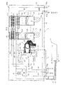
図1に示すように、本実施形態の温水装置WHは、給湯用および暖房用の温水装置本体部1A,1B、ドレイン用の貯留槽3を有する中和器2、ドレイン排出用のポンプP3、ドレイン用配管6、浴槽9に接続された2本の風呂配管7A,7B、各部の動作を制御する制御部4、およびこの温水装置WHの主要構成要素を囲み込んで保護する外装ケース5を備えている。ドレイン排出用のポンプP3は、本発明でいうドレイン強制排出手段の一例に相当する。制御部4は、本発明でいう制御手段の一例に相当する。
1 and 2 show an example of a hot water apparatus according to the present invention.
As shown in FIG. 1, the hot water apparatus WH of the present embodiment includes hot water supply and heating hot water apparatus
給湯用の温水装置本体部1Aは、たとえば台所、洗面所、浴室などに供給される湯を加熱生成するための部分である。暖房用の温水装置本体部1Bは、温水式床暖房装置などの暖房装置の熱媒としての湯水(不凍液なども含まれる)を加熱するための部分である。これら2つの温水装置本体部1A,1Bは、ファン10a,10bによって燃焼用空気が送り込まれるケーシング11a,11b内に配置された燃焼器12a,12b、この燃焼器12a,12bによって発生された燃焼ガスから顕熱および潜熱を回収可能な1次熱交換器13a,13b、および2次熱交換器14a,14bを具備している。
The hot water supply main body 1A for hot water supply is a part for heating and generating hot water supplied to, for example, a kitchen, a washroom, and a bathroom. The heating hot water device
熱交換器14a,13aは、外部から入水口80aおよび配管部80を介して供給されてきた湯水を順次加熱可能であり、加熱された湯水は、配管部81を介して出湯口81aに到達し、所望の給湯先に供給可能である。配管部80,81に接続されたバイパス弁V2は、2次熱交換器14aへの入水量を制御するのに役立つ。熱交換器14a,13aにより加熱された湯水は、浴槽9への湯張りにも利用可能とされている。すなわち、配管部81は、開閉弁V1を有する補助配管部82を介して風呂配管7Bと接続されており、開閉弁V1を開くと、配管部81から風呂配管7Bに湯水が供給される。このことにより、風呂配管(風呂戻り管)7Bに供給されていた湯水の一部は、風呂用ポンプP1を通過して風呂配管(風呂往き管)7A内にも流入し、風呂配管7A,7Bの双方から浴槽9に湯水が供給される。2本の風呂配管7A,7Bは、それぞれの一端が浴槽9に接続されて、一定の湯水循環流路を構成しており、風呂追い焚き動作を行なう場合には、風呂用ポンプP1が駆動して浴槽9の湯水が風呂配管7Bから風呂用ポンプP1に汲み上げられてから熱交換器89により加熱され、その後に風呂配管7Aを通って浴槽9に戻される。後述するように、風呂配管7Aは、ドレイン用配管6が内部に差し込まれた二重管構造部Dを有している。
The
熱交換器14b,13bは、暖房装置(図示略)から入水口83aに入水した戻り湯水を順次加熱可能であり、加熱された湯水は出湯口84aに到達してから前記暖房装置に送り出される。暖房用の湯水加熱は、通常時においては、図3(a)の太線で示すような経路で行なわれる。すなわち、同図において、バルブV4は閉じられており、入水口83aに入水した湯水は、配管部83を通過して2次熱交換器14bに到達した後に、配管部88a、膨張タンク85、ポンプP2、および配管部88bを経由して1次熱交換器13bに到達する。この1次熱交換器13bを通過した湯水は、配管部88c,84を通過して出湯口84aに到達する。ただし、配管部84内を流通する湯水の一部は、符号n1で示す交差部分からバイパス配管88dを通過し、配管部88a内を流通する湯水と混合される。その混合比は、バルブV3により制御可能であり、この制御により出湯温度を目標温度に設定可能である。
The
一方、前記とは異なり、図3(b)の太線で示すような経路での湯水加熱も可能である。同図においては、バルブV3が閉じられ、かつバルブV4が開かれた状態にある。この状態では、1次熱交換器13bにより加熱されてから配管部88cを流れる湯水の一部が、熱交換器89(この熱交換器89は熱交換を行なっていない状態にある)およびバルブV4を通過して交差部分n2に到達し、この交差部分n2において入水口83aから配管部83内に流入した湯水と混合される。この混合により、配管部83から2次熱交換器14bに供給される湯水温度(入水温度)を高めることが可能である。このように2次熱交換器14bへの入水温度を高める動作は、後述するように、2次熱交換器14bにおけるドレイン発生量を減少させる手段として採用することが可能である。
On the other hand, unlike the above, hot water heating in a path as shown by a thick line in FIG. 3B is also possible. In the figure, the valve V3 is closed and the valve V4 is opened. In this state, a part of the hot water flowing through the
中和器2は、2次熱交換器14a,14bによる潜熱回収に伴って発生する酸性のドレインを中和するためのものであって、合成樹脂製の容器20内に粒状の炭酸カルシウムなどの中和剤21が収容された構成を有している。この中和器2の基本的な構成は、たとえば本出願人が提案した特開2007−54781号公報に記載されたものと同様であり、ドレイン用の貯留槽3を備えている。2次熱交換器14a,14bにおいて発生したドレインは、ドレイン受け部15から配管部60を介して中和器2内に導かれ、中和剤21との接触により中和されてから貯留槽3に流入して貯留される。
The
図2によく表われているように、貯留槽3の排出口38には、ドレイン排出用のポンプP3が配管接続されており、貯留槽3内のドレインは、ポンプP3の駆動によりドレイン用配管6を介して後述する所定の箇所に送出し、廃棄することが可能である。貯留槽3には、ドレイン水位の検出手段として、3本の電極33a〜33cが設けられている。電極33aは、グランド電極であり、電極33b,33cは、電極33aとの間でドレインを介して電気導通を生じさせるための電圧印加がなされた電極である。これら電極33a〜33cを備えた構成においては、ドレインの水位が所定の高水位LHにあるか否か、および所定の低水位LLにあるか否かを制御部4において判断することが可能である。ポンプP3は、ドレイン水位が高水位LHになると駆動を開始し、その後にドレイン水位が低水位LLまで低下した時点でその駆動が停止するように制御される。また、中和器2の上部には、ドレインが最大許容水位Lmaxまで上昇した際にその旨を検出するための電極29も設けられている。
As clearly shown in FIG. 2, a drain discharge pump P3 is connected to the
なお、図1においては、膨張タンク85のオーバフロー用配管87を一部分のみ示している。このオーバフロー用配管87については、たとえば図4に示すように、貯留槽3に接続し、膨張タンク85からのオーバフロー水を貯留槽3に流入させるように構成することも可能である。また、この場合において、同図に示すように、貯留槽3の排出口38に、水封トラップ構築用の曲状のパイプ39を接続した構成とすることもできる。このような構成によれば、温水装置WHの設置工事を完了し、給水管80bから膨張タンク85に熱媒としての湯水を供給する際に、膨張タンク85から湯水を積極的にオーバフローさせ、かつこのオーバフロー水を貯留槽3およびパイプ39内に流入させることにより、水封トラップ構造を簡易かつ迅速に構築することが可能である。温水装置WHを設置した直後の未使用時点においては、中和器2内にドレインが未だ流入しておらず、ドレインによる水封構造が構築されていない。このような状態で燃焼器12a,12bを駆動させると、燃焼ガスが中和器2内からドレイン用配管6に向けて進行する虞がある。これに対し、前記した手段によれば、そのような虞を適切に防止することが可能であり、ドレインの排出先が屋内とされる場合に好ましいものとなる。貯留槽3内にオーバフロー水を流入させる場合、たとえばその水位が低水位LLになった時点で、オーバフロー水の流入を停止させるように制御すれば、一連の動作制御も容易なものとなる。
In FIG. 1, only a part of the
ドレイン用配管6は、比較的小径の可撓性を有するホースを用いて構成されており、既述したように、風呂配管7Aに差し込まれ、この差し込み部分が二重管構造部Dとなっている。図2によく表われているように、風呂配管7Aへのドレイン用配管6の差し込みは、たとえば風呂配管7Aの外装ケース5への取付用ジョイント70に設けられた孔部70aを利用して行なわれている。風呂配管7Aの終端には、浴槽9のアダプタ90への取付用ジョイント71が設けられており、このジョイント71に設けられた孔部71aからドレイン用配管6の終端6aが外部に引き出されている。ドレイン用配管6の終端6aは、たとえば浴室の床に設けられた浴槽湯水の排出口(図示略)にドレインを排出可能な配置とされる。二重管構造部Dを設けた構成においては、2本の風呂配管7A,7Bの外部にドレイン用配管6を沿わせた構成と比較すると、それら計3本の配管6,7A,7Bが大きく嵩張ることが抑制され、それらの占有スペースを小さくするといった利点が得られる。
The
制御部4は、マイクロコンピュータなどを用いて構成されており、温水装置WHの各部の動作制御を実行する。加えて、本実施形態においては、給湯動作などを安定的に実行させつつ、貯留槽3からの円滑なドレイン排出を行なうための制御をも実行するように構成されている。その制御内容については、後述する。
The control part 4 is comprised using the microcomputer etc., and performs operation control of each part of the hot water apparatus WH. In addition, the present embodiment is configured to execute control for smoothly discharging the drain from the
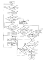
次に、温水装置WHの作用、ならびに制御部4の動作処理手順の一例について、図5に示したフローチャートを参照しつつ説明する。
ただし、以降の説明においては、理解の容易のため、とくに言及しない限りは、給湯用の温水装置本体部1Aを利用した給湯動作について説明する。また、燃焼器12aは、熱交換器13a,14aに所定流量以上の通水があったときに駆動を開始し、その通水量が所定流量未満になったときに停止するように制御されるが、以下の説明においては、熱交換器13a,14aに所定量以上の通水が継続して生じ、燃焼器12aの駆動が継続していることを前提として説明する。
Next, an example of the operation of the hot water device WH and an operation processing procedure of the control unit 4 will be described with reference to the flowchart shown in FIG.
However, in the following description, for easy understanding, a hot water supply operation using the hot water supply main body 1A will be described unless otherwise specified. The
まず、2次熱交換器14aを利用した潜熱回収が行なわれると、これに伴って発生するドレインは中和器2内に導かれて貯留槽3に流入して貯留される。制御部4は、貯留槽3のドレイン水位が高水位LH(本発明でいう第1の所定量の一例に相当)に達すると、その時点でポンプP3の駆動を開始させて貯留槽3からのドレイン排出を実行させる(S1:YES,S2)。次いで、制御部4は、ポンプP3の駆動開始時点から所定時間内にドレイン水位が低下したか否かを判断する(S3)。この判断は、高水位LHの検出用の電極33a,33c間の電気導通状態が所定時間内にオフになるか否かにより行なわれる。前記の所定時間は、たとえば10秒程度であるが、限定されるものではない。貯留槽3内にドレインが新たに流入する量が比較的少なく、かつポンプP3によるドレイン排出が円滑に行なわる場合には、所定時間内にドレイン水位が低下し(S3:YES)。その後ドレイン水位は所定の低水位LLまで低下することとなる(S4:YES)。このような場合、ポンプP3の駆動はその時点で停止され、以降は前記した一連の動作が繰り返される(S5,S1)。
First, when the latent heat recovery using the
一方、前記とは異なり、2次熱交換器14aでのドレイン発生量が多く、ポンプP3によるドレイン排出流量よりも貯留槽3へのドレイン流入量の方が多い場合には、ポンプP3の駆動開始後の所定時間内にドレイン水位は低下しないこととなる(S3:NO)。既述したように、ドレイン用配管6は、比較的小径であって、その配管抵抗が大きく、ドレイン排出流量が少ないために、前記したような事態は生じ易い。このような場合、制御部4は、燃焼器12aの燃焼量を順次減少させて、2次熱交換器14aにおけるドレイン発生量を順次減少させるドレイン逓減処理を実行する(S6,S7:NO,S10:NO,S15)。ただし、このドレイン逓減処理は、ドレイン水位が低水位LL(本発明でいう第2の所定量の一例に相当)に低下した時点で中止する(S7:YES)。
On the other hand, unlike the above, when the amount of drain generated in the
前記ドレイン逓減処理をより詳細に説明すると、まず制御部4は、燃焼器12aの燃焼量を所定量だけ減少させる(S6)。たとえば、燃焼器12aの燃焼量が24号の燃焼号数に対応するものである場合、これを22号の燃焼号数に対応したものとする。このことにより、2次熱交換器14aにおける潜熱回収量が減少し、ドレイン発生量も減少する。なお、図5のフローチャートには示されていないが、好ましくは、燃焼器12aの燃焼量を減少させた際には、出湯流量を抑制することにより、出湯口81aからの出湯温度を大きく低下させることなく目標給湯温度にできる限り近付ける制御が行なわれる。
The drain decreasing process will be described in more detail. First, the control unit 4 decreases the combustion amount of the
制御部4は、前記したように燃焼量を減少させた後には、その時点から所定時間内にドレイン水位が低水位LLまで低下したか否かを判断する(S7)。このステップS7における所定時間は、ステップS3における所定時間と一致している必要はない。また、このステップS7では、ドレイン水位が確実に低下することが確認されればよいため、その確認用の水位としては、低水位LLとは異なる水位(たとえば、高水位LH)とすることもできる。燃焼量を減少させたにも拘わらず、ドレイン水位が低下しない場合には(S7:NO)、その時点での燃焼量が予め定められた最小燃焼量でなければ、その燃焼量をさらに所定量だけ減少させる(S10:NO,S15)。このように燃焼量を減少させる処理は、その燃焼量を減少させた時点から所定時間内にドレイン水位が低水位LLまで低下しない限り、複数回にわたって実行される。このことにより、2次熱交換器14aにおけるドレイン発生量が段階的に徐々に減少していくこととなって、貯留槽3のドレイン水位が低下し易くなる。ドレイン水位が低水位LLまで低下した場合(S7:YES)、制御部4は、その時点でポンプP3の駆動を停止させるとともに、燃焼器12aの燃焼量を、減少前の本来の燃焼量に復帰させる(S8,S9)。ただし、燃焼量の変動をなるべく抑制する観点から、燃焼量を本来の燃焼量に復帰させないように制御してもかまわない。
After reducing the combustion amount as described above, the control unit 4 determines whether or not the drain water level has decreased to the low water level LL within a predetermined time from that point (S7). The predetermined time in step S7 does not need to coincide with the predetermined time in step S3. Moreover, in this step S7, since it is only necessary to confirm that the drain water level is surely lowered, the water level for confirmation can be a water level different from the low water level LL (for example, the high water level LH). . If the drain water level does not decrease despite the reduction in the combustion amount (S7: NO), if the combustion amount at that time is not the predetermined minimum combustion amount, the combustion amount is further increased to a predetermined amount. (S10: NO, S15). As described above, the process for reducing the combustion amount is executed a plurality of times unless the drain water level is lowered to the low water level LL within a predetermined time from the time when the combustion amount is reduced. As a result, the amount of drain generated in the
前記したように、ドレイン逓減処理は、ドレイン水位が高水位LHに達してポンプP3が駆動を開始した場合において、その後の所定時間内にドレイン水位が低下しない場合に限り実行される。したがって、たとえばドレイン水位が高水位LHに達する都度ドレイン逓減処理が実行される場合とは異なり、ドレイン逓減処理が実行される頻度を少なくし、燃焼器12aの燃焼量を不必要に減少させないようにして、湯水温度や湯水流量が安定した給湯動作を継続することができる。また、前記ドレイン逓減処理は、燃焼器12aの燃焼量を所定量ずつ順次減少させていくために、やはり給湯温度や給湯流量に急激な変化を生じさせないようにしつつ、貯留槽3におけるドレイン水位の低下を好適に促進することができる。
As described above, when the drain water level reaches the high water level LH and the pump P3 starts to be driven, the drain diminishing process is executed only when the drain water level does not decrease within a predetermined time thereafter. Therefore, unlike the case where the drain diminishing process is executed each time the drain water level reaches the high water level LH, for example, the frequency of the drain diminishing process is reduced so as not to unnecessarily reduce the combustion amount of the
燃焼器12aの燃焼量が所定の最小燃焼量まで減少した場合には(S10:YES)、その後の時間経過の長短には関係なく、ドレイン水位が低水位LLと最大許容水位Lmaxとのいずれに到達するのかが制御部4によって観察される(S14,S11)。ドレイン発生量よりもドレイン排出量の方が多く、全般的にドレイン水位が低下傾向にあれば、ドレイン水位は、やがて低水位LLとなる(S14:YES)。この場合には、その後にポンプP3の駆動を停止させるステップS8に移行することとなる。前記とは異なり、ドレイン水位が上昇傾向にあれば、ドレイン水位は、やがて最大許容水位Lmaxに達することとなる(S11:YES)。この現象は、中和器2内やその下流域などのドレイン排出経路に詰まりが生じている場合にも生じる。制御部4は、そのような現象を生じた場合には、燃焼器12aの燃焼駆動を停止させるとともに、その旨の報知処理を実行する(S12,S13)。燃焼駆動の停止により、ドレインが新たに発生することが防止され、ドレイン受け15側から中和器2へのドレイン流入が困難となる事態が適切に回避される。前記報知処理は、たとえば制御部4に接続されて台所や浴室に設置されたリモコン(図示略)における画面表示やアラーム音の発生などにより行なわれ、この報知処理によって燃焼器12aの駆動が停止した原因をユーザが的確に察知することができる。なお、ポンプP3の駆動は、燃焼器12aの燃焼停止と略同時期に停止させればよい。
When the combustion amount of the
図5のフローチャートでは省略しているが、制御部4は、次のような制御も行なうように構成されている。すなわち、制御部4は、前記ドレイン逓減処理を実行している際に、前記リモコンなどが操作されることによって、浴槽9への湯張り給湯動作または風呂追い焚き動作を行なうべき旨の指令を受けたときには、この指令に対応した動作を直ちに実行することはなく、その動作の待機モードを設定する。次いで、制御部4は、その後にドレイン水位が低水位LLまで低下すると、その時点で前記待機モードを解除し、浴槽9への湯張り給湯動作または風呂追い焚き動作を開始させる。このような制御によれば、浴槽9への湯張り給湯動作や風呂追い焚き動作に起因して、ドレイン水位が上昇することが防止され、実行中のドレイン逓減処理を早期に終了させることができる。また、ドレイン水位が低水位LLまで低下した後には、制御部4の制御によって、浴槽9への湯張り給湯動作または風呂追い焚き動作が開始されるために、ユーザがそれらの動作を行なうための操作を再度行なう煩わしさもない。なお、浴槽9への湯張り給湯動作や風呂追い焚き動作が実行されている場合において、ドレイン水位が高水位LLに達し、所定時間内にその水位が低下しない場合には、前記した一般給湯の場合と同様なドレイン逓減処理が実行されることとなる。
Although omitted in the flowchart of FIG. 5, the control unit 4 is configured to perform the following control. That is, the control unit 4 receives a command to perform a hot water supply operation or a bath reheating operation to the
制御部4は、燃焼器12aが駆動燃焼する場合には、前記したような一連の動作制御を実行するが、燃焼器12bが燃焼駆動する場合においても、前記したのと同様な制御を実行するように構成されている。
The control unit 4 executes the series of operation control as described above when the
本発明は、上述した実施形態の内容に限定されない。本発明に係る温水装置の各部の具体的な構成は、種々に設計変更自在である。 The present invention is not limited to the contents of the above-described embodiment. The specific configuration of each part of the hot water device according to the present invention can be varied in design in various ways.
ドレイン逓減処理は、熱交換器を利用した湯水加熱動作を停止させることなく、ドレイン発生量を複数段階で順次減少させていく処理である。たとえば、熱交換器への湯水の入水温度を高くすることによっても、ドレイン発生量を減少させることが可能であり、このような手段を複合的に採用してもかまわない。既述したように、図3(a)に示す状態から図3(b)に示す状態に切り替えることにより、2次熱交換器14bへの入水温度を高くし、ドレイン発生量を少なくすることが可能である。
Drain decreasing process, without stopping the hot water heating operation using the heat exchanger, Ru processing der to successively reduce the drain generation amount in a plurality of stages. For example, it is possible to reduce the amount of drain generated by raising the temperature of hot water entering the heat exchanger, and such means may be used in combination . As described above, by switching from the state shown in FIG. 3 (a) to the state shown in FIG. 3 (b), the temperature of water entering the
本発明でいう加熱用気体としては、燃焼器により発生された燃焼ガスに代えて、たとえばコージェネシステム用のガスエンジンなどから排出される高温の排ガス(潜熱を含むガス)を利用することも可能である。このような排ガスを利用する場合、ドレイン発生量を減少させる手段としては、熱交換器に作用する排ガスの量を減少させるといった手段を用いることも可能である。 As the heating gas in the present invention, it is also possible to use high-temperature exhaust gas (gas containing latent heat) discharged from a gas engine for a cogeneration system, for example, instead of the combustion gas generated by the combustor. is there. When such exhaust gas is used, means for reducing the amount of exhaust gas acting on the heat exchanger can be used as means for reducing the amount of generated drain.
ドレイン用の貯留槽は、中和器と一体的に設けられていなくてもよく、中和器とは分離したドレインタンクとして構成されていてもかまわない。本発明は、ドレインの中和処理を主眼するものではなく、中和器自体は必須ではない。ドレイン用配管については、風呂配管に差し込まれていない構成とすることが可能であり、ドレインの排出先としても、浴室の排水口以外の部分とすることができる。ドレイン強制排出手段としては、電動式のポンプに代えて、たとえば燃焼ガスなどの圧力を利用してドレインを強制的に排出させるといった手段を採用することもできる。 The drain storage tank does not have to be provided integrally with the neutralizer, and may be configured as a drain tank separated from the neutralizer. The present invention does not focus on the neutralization treatment of the drain, and the neutralizer itself is not essential. The drain pipe can be configured so as not to be inserted into the bath pipe, and the drain discharge destination can be a portion other than the drain port of the bathroom. As the drain forcibly discharging means, means for forcibly discharging the drain using the pressure of combustion gas, for example, can be employed instead of the electric pump.
本発明に係る温水装置は、上述した実施形態とは異なり、給湯用と暖房用の2つの温水装置本体部が組み合わされた構成でなくてもよく、たとえば暖房用の機能を有しない給湯用の温水装置として構成されていてもよいことは勿論である。 Unlike the above-described embodiment, the hot water device according to the present invention may not have a configuration in which two hot water device main bodies for hot water supply and heating are combined, for example, for hot water supply that does not have a heating function. Of course, it may be configured as a hot water device.
Claims (4)
前記熱回収に伴って発生するドレインを貯留可能な貯留槽と、
この貯留槽におけるドレイン貯留量が第1の所定量に達したときに、前記ドレインを前記貯留槽の外部に排出するように動作するドレイン強制排出手段と、
を備えている、温水装置であって、
前記貯留槽におけるドレイン貯留量が前記第1の所定量に達して前記ドレイン強制排出手段が動作を開始した場合に、その後の所定時間内に前記ドレイン貯留量が減少するか否かを判断する制御手段をさらに備えており、
この制御手段は、前記所定時間内に前記ドレイン貯留量が減少していないと判断したときには、前記熱交換器を利用した湯水加熱動作を停止させることなく、前記燃焼器の燃焼量を所定量ずつ減少させることによりドレイン発生量を複数段階で順次減少させていくドレイン逓減処理を開始し、かつこの処理の実行過程において、前記ドレイン貯留量が第2の所定量未満に減少した際には、前記ドレイン逓減処理を中止し、前記燃焼器の燃焼量を前記ドレイン逓減処理を開始する前の本来の燃焼量に復帰させるように構成されていることを特徴とする、温水装置。 A heat exchanger for performing heat recovery from the heating gas generated by the combustor to perform hot water heating,
A storage tank capable of storing a drain generated along with the heat recovery; and
Drain forced discharge means that operates to discharge the drain to the outside of the storage tank when the drain storage amount in the storage tank reaches a first predetermined amount;
A hot water device comprising:
Control for determining whether or not the drain storage amount decreases within a predetermined time after the drain storage amount in the storage tank reaches the first predetermined amount and the drain forced discharge means starts operating. Further comprising means,
When it is determined that the drain storage amount has not decreased within the predetermined time, the control means sets the combustion amount of the combustor by a predetermined amount without stopping the hot water heating operation using the heat exchanger. By starting the drain diminishing process that sequentially decreases the drain generation amount in a plurality of stages by decreasing, and in the process of executing this process, when the drain storage amount decreases below the second predetermined amount , The hot water apparatus is configured to stop the drain decreasing process and to restore the combustion amount of the combustor to the original combustion amount before starting the drain decreasing process .
前記制御手段は、前記ドレイン逓減処理を実行しているときには、前記浴槽への湯張り給湯動作または前記風呂追い焚き動作を行なうべき操作指令を受けた場合であっても、この指令に対応した動作を実行することなくその待機モードを設定し、その後に前記ドレイン逓減処理を終了した時点で、前記待機モードを解除して前記浴槽への湯張り給湯動作または前記風呂追い焚き動作の実行を開始するように構成されている、請求項1または2に記載の温水装置。 It is possible to perform at least one of hot water supply operation to the bathtub and bathing operation,
When the control means is performing the drain diminishing process, even if it receives an operation command to perform a hot water supply operation to the bathtub or the bath reheating operation, an operation corresponding to this command The standby mode is set without executing, and when the drain diminishing process is finished, the standby mode is canceled and the hot water supply operation or the bath reheating operation to the bathtub is started. The hot water apparatus according to claim 1 or 2, configured as described above.
前記風呂配管および前記ドレイン用配管は、前記風呂配管内に前記ドレイン用配管が差し込まれた二重管構造とされている、請求項1ないし3のいずれかに記載の温水装置。 A bath pipe for performing at least one of a hot water supply operation and a bath chase operation to the bathtub, and a drain pipe connected to the downstream side of the drain forced discharge means,
The hot water apparatus according to any one of claims 1 to 3 , wherein the bath pipe and the drain pipe have a double pipe structure in which the drain pipe is inserted into the bath pipe .
Priority Applications (1)
| Application Number | Priority Date | Filing Date | Title |
|---|---|---|---|
| JP2009176715A JP5522357B2 (en) | 2009-07-29 | 2009-07-29 | Water heater |
Applications Claiming Priority (1)
| Application Number | Priority Date | Filing Date | Title |
|---|---|---|---|
| JP2009176715A JP5522357B2 (en) | 2009-07-29 | 2009-07-29 | Water heater |
Publications (2)
| Publication Number | Publication Date |
|---|---|
| JP2011033202A JP2011033202A (en) | 2011-02-17 |
| JP5522357B2 true JP5522357B2 (en) | 2014-06-18 |
Family
ID=43762456
Family Applications (1)
| Application Number | Title | Priority Date | Filing Date |
|---|---|---|---|
| JP2009176715A Active JP5522357B2 (en) | 2009-07-29 | 2009-07-29 | Water heater |
Country Status (1)
| Country | Link |
|---|---|
| JP (1) | JP5522357B2 (en) |
Families Citing this family (2)
| Publication number | Priority date | Publication date | Assignee | Title |
|---|---|---|---|---|
| JP5618962B2 (en) * | 2011-10-25 | 2014-11-05 | リンナイ株式会社 | Drain neutralizer |
| JP6192680B2 (en) * | 2015-05-11 | 2017-09-06 | 株式会社パロマ | Water heater |
Family Cites Families (7)
| Publication number | Priority date | Publication date | Assignee | Title |
|---|---|---|---|---|
| JP4074258B2 (en) * | 2004-03-16 | 2008-04-09 | 高木産業株式会社 | Hot water supply / remembrance device and its waste water management method |
| JP2006183937A (en) * | 2004-12-27 | 2006-07-13 | Takagi Ind Co Ltd | Method and apparatus for discharging drain |
| JP2007271249A (en) * | 2006-03-10 | 2007-10-18 | Gastar Corp | Hot water supply device for bath |
| JP2008180400A (en) * | 2007-01-23 | 2008-08-07 | Matsushita Electric Ind Co Ltd | Hot-water supply heating device |
| JP5121378B2 (en) * | 2007-10-05 | 2013-01-16 | 株式会社パロマ | Water heater |
| JP5117886B2 (en) * | 2007-11-01 | 2013-01-16 | 大阪瓦斯株式会社 | Piping structure for bath equipment and drain drain pipe insertion method |
| JP4755235B2 (en) * | 2008-09-26 | 2011-08-24 | 高木産業株式会社 | Heat source equipment |
-
2009
- 2009-07-29 JP JP2009176715A patent/JP5522357B2/en active Active
Also Published As
| Publication number | Publication date |
|---|---|
| JP2011033202A (en) | 2011-02-17 |
Similar Documents
| Publication | Publication Date | Title |
|---|---|---|
| JP4700318B2 (en) | Drain discharge device for heat source machine | |
| JP2008008587A (en) | Bath hot water supply equipment | |
| JP2009150576A (en) | Water heating system equipped with neutralizer | |
| JP2006300481A (en) | Bath hot water supply device | |
| JP4986911B2 (en) | Hot water storage water heater | |
| JP5522357B2 (en) | Water heater | |
| JP4755235B2 (en) | Heat source equipment | |
| JP5256882B2 (en) | Water heater | |
| JP5288172B2 (en) | Water heater | |
| JP4974651B2 (en) | Hot water supply apparatus, drain treatment method thereof, and drain treatment program thereof | |
| JP2010112659A (en) | Water heater | |
| JP5185733B2 (en) | Heat utilization equipment and heat source equipment | |
| JP4220936B2 (en) | Heat source equipment | |
| JP5656423B2 (en) | Drain drainage system for latent heat recovery type heating device | |
| JP5179914B2 (en) | Bath water heater | |
| JP5130258B2 (en) | Cogeneration system | |
| JP2008180400A (en) | Hot-water supply heating device | |
| JP6362469B2 (en) | Hot water storage system | |
| JP5361981B2 (en) | Hot water storage water heater | |
| JP5456915B2 (en) | Bath water heater | |
| JP5122261B2 (en) | Bath facilities | |
| JP5424028B2 (en) | Water heater | |
| JP2004125228A (en) | Water heater | |
| JP5892154B2 (en) | Water heater | |
| JP6253482B2 (en) | Instant hot water unit |
Legal Events
| Date | Code | Title | Description |
|---|---|---|---|
| A621 | Written request for application examination |
Free format text: JAPANESE INTERMEDIATE CODE: A621 Effective date: 20120620 |
|
| A977 | Report on retrieval |
Free format text: JAPANESE INTERMEDIATE CODE: A971007 Effective date: 20130703 |
|
| A131 | Notification of reasons for refusal |
Free format text: JAPANESE INTERMEDIATE CODE: A131 Effective date: 20130711 |
|
| A521 | Request for written amendment filed |
Free format text: JAPANESE INTERMEDIATE CODE: A523 Effective date: 20130906 |
|
| A131 | Notification of reasons for refusal |
Free format text: JAPANESE INTERMEDIATE CODE: A131 Effective date: 20131206 |
|
| A521 | Request for written amendment filed |
Free format text: JAPANESE INTERMEDIATE CODE: A523 Effective date: 20140128 |
|
| TRDD | Decision of grant or rejection written | ||
| A01 | Written decision to grant a patent or to grant a registration (utility model) |
Free format text: JAPANESE INTERMEDIATE CODE: A01 Effective date: 20140312 |
|
| A61 | First payment of annual fees (during grant procedure) |
Free format text: JAPANESE INTERMEDIATE CODE: A61 Effective date: 20140325 |
|
| R150 | Certificate of patent or registration of utility model |
Ref document number: 5522357 Country of ref document: JP Free format text: JAPANESE INTERMEDIATE CODE: R150 |
|
| R250 | Receipt of annual fees |
Free format text: JAPANESE INTERMEDIATE CODE: R250 |
|
| R250 | Receipt of annual fees |
Free format text: JAPANESE INTERMEDIATE CODE: R250 |
|
| R250 | Receipt of annual fees |
Free format text: JAPANESE INTERMEDIATE CODE: R250 |