JP5520933B2 - Method and apparatus for generating a mid-infrared laser for use in ultrasonic inspection - Google Patents
Method and apparatus for generating a mid-infrared laser for use in ultrasonic inspection Download PDFInfo
- Publication number
- JP5520933B2 JP5520933B2 JP2011509684A JP2011509684A JP5520933B2 JP 5520933 B2 JP5520933 B2 JP 5520933B2 JP 2011509684 A JP2011509684 A JP 2011509684A JP 2011509684 A JP2011509684 A JP 2011509684A JP 5520933 B2 JP5520933 B2 JP 5520933B2
- Authority
- JP
- Japan
- Prior art keywords
- wave
- wavelength
- optical
- converter
- laser
- Prior art date
- Legal status (The legal status is an assumption and is not a legal conclusion. Google has not performed a legal analysis and makes no representation as to the accuracy of the status listed.)
- Expired - Fee Related
Links
Images


Classifications
-
- G—PHYSICS
- G01—MEASURING; TESTING
- G01N—INVESTIGATING OR ANALYSING MATERIALS BY DETERMINING THEIR CHEMICAL OR PHYSICAL PROPERTIES
- G01N29/00—Investigating or analysing materials by the use of ultrasonic, sonic or infrasonic waves; Visualisation of the interior of objects by transmitting ultrasonic or sonic waves through the object
- G01N29/22—Details, e.g. general constructional or apparatus details
- G01N29/24—Probes
-
- G—PHYSICS
- G01—MEASURING; TESTING
- G01N—INVESTIGATING OR ANALYSING MATERIALS BY DETERMINING THEIR CHEMICAL OR PHYSICAL PROPERTIES
- G01N29/00—Investigating or analysing materials by the use of ultrasonic, sonic or infrasonic waves; Visualisation of the interior of objects by transmitting ultrasonic or sonic waves through the object
- G01N29/04—Analysing solids
- G01N29/12—Analysing solids by measuring frequency or resonance of acoustic waves
-
- G—PHYSICS
- G01—MEASURING; TESTING
- G01N—INVESTIGATING OR ANALYSING MATERIALS BY DETERMINING THEIR CHEMICAL OR PHYSICAL PROPERTIES
- G01N21/00—Investigating or analysing materials by the use of optical means, i.e. using sub-millimetre waves, infrared, visible or ultraviolet light
- G01N21/17—Systems in which incident light is modified in accordance with the properties of the material investigated
- G01N21/1702—Systems in which incident light is modified in accordance with the properties of the material investigated with opto-acoustic detection, e.g. for gases or analysing solids
-
- G—PHYSICS
- G01—MEASURING; TESTING
- G01N—INVESTIGATING OR ANALYSING MATERIALS BY DETERMINING THEIR CHEMICAL OR PHYSICAL PROPERTIES
- G01N21/00—Investigating or analysing materials by the use of optical means, i.e. using sub-millimetre waves, infrared, visible or ultraviolet light
- G01N21/17—Systems in which incident light is modified in accordance with the properties of the material investigated
-
- G—PHYSICS
- G01—MEASURING; TESTING
- G01N—INVESTIGATING OR ANALYSING MATERIALS BY DETERMINING THEIR CHEMICAL OR PHYSICAL PROPERTIES
- G01N21/00—Investigating or analysing materials by the use of optical means, i.e. using sub-millimetre waves, infrared, visible or ultraviolet light
- G01N21/84—Systems specially adapted for particular applications
- G01N21/88—Investigating the presence of flaws or contamination
- G01N21/8806—Specially adapted optical and illumination features
-
- G—PHYSICS
- G01—MEASURING; TESTING
- G01N—INVESTIGATING OR ANALYSING MATERIALS BY DETERMINING THEIR CHEMICAL OR PHYSICAL PROPERTIES
- G01N29/00—Investigating or analysing materials by the use of ultrasonic, sonic or infrasonic waves; Visualisation of the interior of objects by transmitting ultrasonic or sonic waves through the object
- G01N29/22—Details, e.g. general constructional or apparatus details
- G01N29/24—Probes
- G01N29/2418—Probes using optoacoustic interaction with the material, e.g. laser radiation, photoacoustics
-
- G—PHYSICS
- G01—MEASURING; TESTING
- G01N—INVESTIGATING OR ANALYSING MATERIALS BY DETERMINING THEIR CHEMICAL OR PHYSICAL PROPERTIES
- G01N29/00—Investigating or analysing materials by the use of ultrasonic, sonic or infrasonic waves; Visualisation of the interior of objects by transmitting ultrasonic or sonic waves through the object
- G01N29/34—Generating the ultrasonic, sonic or infrasonic waves, e.g. electronic circuits specially adapted therefor
- G01N29/348—Generating the ultrasonic, sonic or infrasonic waves, e.g. electronic circuits specially adapted therefor with frequency characteristics, e.g. single frequency signals, chirp signals
-
- G—PHYSICS
- G01—MEASURING; TESTING
- G01N—INVESTIGATING OR ANALYSING MATERIALS BY DETERMINING THEIR CHEMICAL OR PHYSICAL PROPERTIES
- G01N21/00—Investigating or analysing materials by the use of optical means, i.e. using sub-millimetre waves, infrared, visible or ultraviolet light
- G01N21/17—Systems in which incident light is modified in accordance with the properties of the material investigated
- G01N21/1702—Systems in which incident light is modified in accordance with the properties of the material investigated with opto-acoustic detection, e.g. for gases or analysing solids
- G01N2021/1706—Systems in which incident light is modified in accordance with the properties of the material investigated with opto-acoustic detection, e.g. for gases or analysing solids in solids
-
- G—PHYSICS
- G01—MEASURING; TESTING
- G01N—INVESTIGATING OR ANALYSING MATERIALS BY DETERMINING THEIR CHEMICAL OR PHYSICAL PROPERTIES
- G01N21/00—Investigating or analysing materials by the use of optical means, i.e. using sub-millimetre waves, infrared, visible or ultraviolet light
- G01N21/84—Systems specially adapted for particular applications
- G01N2021/8472—Investigation of composite materials
-
- G—PHYSICS
- G01—MEASURING; TESTING
- G01N—INVESTIGATING OR ANALYSING MATERIALS BY DETERMINING THEIR CHEMICAL OR PHYSICAL PROPERTIES
- G01N2291/00—Indexing codes associated with group G01N29/00
- G01N2291/02—Indexing codes associated with the analysed material
- G01N2291/023—Solids
Landscapes
- Physics & Mathematics (AREA)
- Health & Medical Sciences (AREA)
- Life Sciences & Earth Sciences (AREA)
- Chemical & Material Sciences (AREA)
- Analytical Chemistry (AREA)
- Biochemistry (AREA)
- General Health & Medical Sciences (AREA)
- General Physics & Mathematics (AREA)
- Immunology (AREA)
- Pathology (AREA)
- Optics & Photonics (AREA)
- Acoustics & Sound (AREA)
- Investigating Or Analyzing Materials By The Use Of Ultrasonic Waves (AREA)
- Optical Modulation, Optical Deflection, Nonlinear Optics, Optical Demodulation, Optical Logic Elements (AREA)
Description
本発明は、概略的には、非破壊試験の分野に関する。より具体的には、本発明は、中赤外線波長の発生レーザービームを形成する方法及びシステムに関する。 The present invention generally relates to the field of nondestructive testing. More specifically, the present invention relates to a method and system for forming a generated laser beam of mid-infrared wavelengths.
複合材料の作成における最近の進歩は、複合材料の使用を多様な用途に拡大した。低重量と相まったその高い強度及び耐久性のおかげで、複合材は、或る種の耐荷重構成要素の基部材料として金属及び金属合金に代わりつつある。例えば、複合材は、自動車、船及び飛行機のような車両の本体部品及び構造に用いられる材料として現在一般的に使用されている。しかしながら、複合材の機械的な完全性を確実にするため、厳しい検査が必要とされる。検査は、標準的には複合材から作られる構成要素の製造時、及び構成要素の寿命に亘って定期的に必要である。 Recent advances in the creation of composite materials have expanded the use of composite materials to a variety of applications. Thanks to its high strength and durability combined with low weight, composites are replacing metals and metal alloys as the base material for certain load bearing components. For example, composite materials are now commonly used as materials used in vehicle body parts and structures such as automobiles, ships and airplanes. However, rigorous inspection is required to ensure the mechanical integrity of the composite. Inspection is typically required during manufacture of components made from composite materials and periodically over the life of the components.
レーザー超音波は、複合材料から作られた対象を検査する方法の1つの実例である。当該方法は、複合材の一部分にパルスレーザーを放射することによって複合材の表面に超音波振動を発生させることを含んでいる。検出レーザービームは、振動面に向けられ、表面振動によって散乱される。収集光学素子は、散乱した検出レーザー光を受け入れ、処置に導く。散乱レーザー光処理は、標準的には、収集光学素子と連結された干渉計を用いて行われる。複合材に関する情報は、散乱光処理で突き止めることが可能であり、情報は、亀裂、層間剥離、空隙率及び繊維情報の検出を含む。 Laser ultrasound is one example of a method for inspecting an object made from a composite material. The method includes generating ultrasonic vibrations on the surface of the composite by emitting a pulsed laser to a portion of the composite. The detection laser beam is directed to the vibration surface and scattered by surface vibration. The collection optics receives the scattered detection laser light and directs it to treatment. Scattered laser light processing is typically performed using an interferometer coupled to the collection optics. Information about the composite can be ascertained with scattered light processing and information includes detection of cracks, delamination, porosity and fiber information.
本明細書に開示しているのは、放射波をポンプレーザーから第1の光変換器へ方向付けることから成る超音波探傷試験の方法であって、第1の光変換器は、放射波を信号波及びアイドラー波に変換し、アイドラー波の波長は、中赤外線領域に含まれ、信号波及びアイドラー波を第2の光変換器へ方向付け、第2の光変換器は、信号波の波長を中赤外線領域に変換し、アイドラー波は、実質的には変化せずに第2の光変換器を通過し、アイドラー波は、単一の出力波を形成するために変換された信号波と結合し、検査対象を超音波検査するために、単一の出力波を検査対象の検査表面に方向付ける。 Disclosed herein is a method of ultrasonic flaw testing comprising directing a radiated wave from a pump laser to a first optical transducer, wherein the first optical transducer transmits the radiated wave. The signal wave and the idler wave are converted, the wavelength of the idler wave is included in the mid-infrared region, the signal wave and the idler wave are directed to the second optical converter, and the second optical converter transmits the wavelength of the signal wave To the mid-infrared region, the idler wave passes through the second optical converter substantially unchanged, and the idler wave is converted to the signal wave converted to form a single output wave. Combine and direct a single output wave to the inspection surface to be inspected for ultrasonic inspection of the inspection object.
出力波は、検査面上で超音波変位を発生させるため、及び/又は検査面上で超音波変位を検出するための発生波であってもよい。検査面は、複合材から成っていてもよい。1つの実施形態では、第1の光変換器は、光パラメトリック発振器である。1つの実施形態では、第2の光変換器は、光パラメトリック変換器又は差周波発生器とすることができる。任意選択的には、第1及び第2の光変換器は、単一の結晶に結合される。第1の光変換器及び第2の光変換器は、結晶の異なる部分に分離され、任意選択的には、第1の光変換器及び第2の光変換器は、単一の結晶の中に統合される。 The output wave may be a generated wave for generating an ultrasonic displacement on the inspection surface and / or for detecting an ultrasonic displacement on the inspection surface. The inspection surface may be made of a composite material. In one embodiment, the first optical converter is an optical parametric oscillator. In one embodiment, the second optical converter can be an optical parametric converter or a difference frequency generator. Optionally, the first and second light converters are combined into a single crystal. The first light converter and the second light converter are separated into different portions of the crystal, and optionally, the first light converter and the second light converter are in a single crystal. Integrated into.
超音波試験の方法の1つの任意選択的な実施形態では、ポンプレーザー波の波長は、約1.064ミクロンである。超音波試験の方法の1つの任意選択的な実施形態では、信号波の波長は、約1.594ミクロンである。超音波試験の方法の1つの任意選択的な実施形態では、アイドラー波の波長は、約3.2ミクロンである。本発明の方法の出力波の波長は、約3ミクロンから約4ミクロンの範囲であってもよい。任意選択的には、超音波試験の本発明の方法の1つの実施形態では、出力波の波長は、約3.2ミクロンである。 In one optional embodiment of the ultrasonic test method, the wavelength of the pump laser wave is about 1.064 microns. In one optional embodiment of the ultrasonic test method, the wavelength of the signal wave is about 1.594 microns. In one optional embodiment of the ultrasonic test method, the wavelength of the idler wave is about 3.2 microns. The wavelength of the output wave of the method of the present invention may range from about 3 microns to about 4 microns. Optionally, in one embodiment of the inventive method of ultrasonic testing, the wavelength of the output wave is about 3.2 microns.
本明細書に開示しているのは、約1.064ミクロンの波長を有する入力レーザー波を約3.2ミクロンの波長を有する信号波及び約1.594ミクロンの波長を有するアイドラー波に変換することと、信号波の波長を約3.2ミクロンに変換することと、アイドラー波及び変換された信号波を複合波として目標表面に方向付けることによって、目標対象の目標表面上に超音波振動を生成することと、から成る試験対象にレーザー超音波試験を行う方法である。当該方法は、第2の複合波を発生することと、第2の複合波を振動している目標表面に方向付けることと、第2の複合波を用いて目標表面変位を検出することと、を更に含んでもよい。入力レーザー波を変換するステップは、入力波を光パラメトリック発振器に方向付けることを含んでいてもよい。変換信号波を形成するステップは、信号波及びアイドラー波を周波数変換器に方向付けることを含んでいてもよく、周波数変換器は、光パラメトリック発振器及び差周波発生器であってもよい。 Disclosed herein is to convert an input laser wave having a wavelength of about 1.064 microns into a signal wave having a wavelength of about 3.2 microns and an idler wave having a wavelength of about 1.594 microns. And by converting the wavelength of the signal wave to about 3.2 microns and directing the idler wave and the converted signal wave as a composite wave to the target surface, ultrasonic vibrations on the target surface of the target object A method for performing a laser ultrasonic test on a test object consisting of: The method includes generating a second composite wave, directing the second composite wave to a vibrating target surface, detecting the target surface displacement using the second composite wave; May further be included. Converting the input laser wave may include directing the input wave to an optical parametric oscillator. The step of forming the converted signal wave may include directing the signal wave and idler wave to a frequency converter, and the frequency converter may be an optical parametric oscillator and a difference frequency generator.
本開示は、入力レーザー源と、入力レーザー源から入力波を受け取るために連結され、入力波をアイドラー波及び信号波に変換するように構成されている第1の光周波数変換器と、を含むレーザー超音波試験システムを更に含み、アイドラー波及び信号波は、異なる波長を有している。更に試験システムと一体化して含むことが可能なものは、アイドラー波及び信号波を受け取るために連結され、信号波の波長をアイドラー波と実質的に同じ波長に変換し、且つ変換された信号波及びアイドラー波を含む複合出力波を発するように構成された第2の光周波数変換器であって、複合出力波は、目標表面上に超音波振動を発生するために、目標対象の目標表面に方向付けることが可能である。このシステムは、更に、目標表面に方向付けることが可能であり且つ目標表面振動を記録するように構成されている検出レーザーを含んでいてもよい。 The present disclosure includes an input laser source and a first optical frequency converter coupled to receive an input wave from the input laser source and configured to convert the input wave into an idler wave and a signal wave. Further comprising a laser ultrasonic test system, the idler wave and the signal wave have different wavelengths. What can further be integrated with the test system is coupled to receive idler and signal waves, converts the wavelength of the signal wave to substantially the same wavelength as the idler wave, and the converted signal wave. And a second optical frequency converter configured to emit a composite output wave including an idler wave, wherein the composite output wave is applied to the target surface of the target object to generate ultrasonic vibrations on the target surface. Can be oriented. The system may further include a detection laser that can be directed to the target surface and configured to record the target surface vibration.
入力レーザー波は、約1.064ミクロンの波長を有していてもよい。アイドラー波及び変換された信号波は、約3ミクロンから約4ミクロンの範囲の波長を有していてもよい。アイドラー波及び変換された信号波は、約3.2ミクロンの波長を有していてもよい。第1の光変換器は、光パラメトリック発振器であってもよい。第2の光変換器は、光パラメトリック変換器又は差周波発生器であってもよい。 The input laser wave may have a wavelength of about 1.064 microns. The idler wave and the converted signal wave may have a wavelength in the range of about 3 microns to about 4 microns. The idler wave and the converted signal wave may have a wavelength of about 3.2 microns. The first optical converter may be an optical parametric oscillator. The second optical converter may be an optical parametric converter or a difference frequency generator.
本発明の特徴及び恩恵の一部を述べてきたが、その他のものについては、添付図面と関連付けながら説明が進むにつれて明らかになってゆくであろう。 While some of the features and benefits of the present invention have been set forth, others will become apparent as the description proceeds in connection with the accompanying drawings.
本発明は、好適な実施形態と関連させて説明するが、本発明をそのような実施形態に限定することを意図していないことが理解されるであろう。それどころか、添付の特許請求の範囲によって定義されるように、本発明の精神及び範囲の中に含まれ得るものとして、全ての代替物、修正物、等価物を含むように意図している。 While the invention will be described in conjunction with the preferred embodiments, it will be understood that it is not intended to limit the invention to such embodiments. On the contrary, the intention is to cover all alternatives, modifications, and equivalents as may be included within the spirit and scope of the invention as defined by the appended claims.
これより、本発明を、本発明の実施形態を示している添付図面を参照しながらより詳しく説明する。しかしながら、本発明は、多くの異なる形態で具現化されてもよく、本明細書に説明する図示の実施形態に限定されるものと解釈されるべきではなく、寧ろ本開示が綿密及び完全なものであるように、且つ本発明の範囲を当業者に十分に伝えるようにこれらの実施形態は提供されている。類似番号は、各図を通して類似要素を指している。添付図面を参照するうえでの便宜上、方向を示す用語は、参照及び例証のためだけに使用されている。例えば「上部の」、「下部の」、「上方に」、「下方に」などの方向を示す用語は、相関的な位置を説明する目的で使用されている。 The present invention will now be described in more detail with reference to the accompanying drawings showing embodiments of the invention. However, the present invention may be embodied in many different forms and should not be construed as limited to the illustrated embodiments described herein; rather, the present disclosure is thorough and complete. These embodiments are provided so that the scope of the invention may be well communicated to those skilled in the art. Similar numbers refer to similar elements throughout the figures. For convenience in reference to the accompanying drawings, the directional terminology is used for reference and illustration only. For example, terms indicating directions such as “upper”, “lower”, “upward”, “downward” and the like are used for the purpose of describing a relative position.
修正物及び等価物が当業者には自明のように、本発明は、表示及び説明している構造、動作、正確な材料又は実施形態の正確な詳細に限定されないものと理解されたい。図面及び明細書では、本発明の例証的な実施形態を開示しており、特定の用語が使用されているが、それらの用語は単に一般的及び説明的な意味でのみ使われており、制限的な目的で使用されているわけではない。このような次第で、本発明は、したがって、添付の特許請求の範囲によってのみ制限されるべきである。 It will be understood that the invention is not limited to the exact details of the structures, operations, precise materials or embodiments shown and described, as modifications and equivalents will be apparent to those skilled in the art. In the drawings and specification, there have been disclosed exemplary embodiments of the invention and specific terminology has been used, but these terms are merely used in a generic and descriptive sense and are not limiting. It is not used for specific purposes. As such, the invention should therefore be limited only by the scope of the appended claims.
図1は、レーザー超音波検出システム10の一実施形態の側面斜視図である。検出システム10は、発生ビーム14を発するために形成され、検査目標15に方向付けられるレーザー超音波ユニット12を備えている。発生ビーム14は、検査表面上16の検査目標15に接触する。発生ビーム14は、検査表面16上に対応する波動変位18を発生させるために検査表面16を熱弾性的に膨張させる。1つの実施形態では、発生ビーム14は、検査表面16上に波動変位18を発生させるように構成されているパルスレーザーである。検出ビーム20は、レーザー超音波ユニット12からも発しているように図示されており、発生ビーム14の周囲で同軸に示されている。同じレーザー超音波ユニット12から発していても、検出ビーム及び発生ビーム(14、20)は、異なる源から発生されている。しかしながら、検出ビーム20は、任意選択的には、異なるユニット、並びに異なる場所から発してもよい。既知のように、検出ビーム20は、位相変調光21を形成するために波動変位18に接触することで散乱、反射及び位相変調される検出波を備えている。検出ビーム20からの位相変調光21は、その後収集光学素子23で受け取られ、検査目標15についての情報を確定するために処理される。検出ビーム及び発生ビーム(14、20)は、表面16全体に関する情報を獲得するために目標15全域で走査され得る。ビーム(14、20)を走査するために使用される機構(図示せず)は、レーザー超音波ユニット12の中に格納されていてもよい。機構を制御し、且つ任意選択的に収集光学素子によって記録されたデータを処理する処理装置(図示せず)も、同様に、レーザー超音波ユニット12に格納されていてもよい。収集光学素子23は、レーザー超音波ユニット12から分離していて、矢印Aを通じてレーザー超音波ユニット12と通信するように図示されているが、収集光学素子は、レーザー超音波ユニット12に含まれていてもよい。
FIG. 1 is a side perspective view of one embodiment of a laser ultrasound detection system 10. The detection system 10 includes a
次に図2を参照すると、中赤外線発生器22の1つの実施形態を概略図で図示している。下文で更に詳細に説明するように、中赤外線発生器22は、図1の発生レーザービーム14の1つに使用され得る出力波を発生する。図示する実施形態では、中赤外線発生器22は、第1の光周波数変換器30に方向付けられたポンプレーザービーム26を発するポンプレーザー24を備えている。第1の光周波数変換器30は、1つのポンプ入力波を2つの波、(1)アイドラー波32及び(2)信号波36に変換する。一部の残りのポンプレーザー波34は、変換器30を通過する。各波(32、34、36)は、異なる波長になっている。変換器は、100%効率を下回って作動し、ポンプレーザービームからのエネルギーのごく一部はその中を通過することができる。
Referring now to FIG. 2, one embodiment of the
第1の光周波数変換器30から発する波は、第2の光周波数変換器38に方向付けられる。第2の光周波数変換器38は、周波数波長及びエネルギーなどの波動特性に何ら影響を及ぼすことなくアイドラー波32が自由に通過できるように構成されている。信号波36の波長は、しかしながら、実質的にはアイドラー波32の波長と同じになるように第2の光周波数変換器38の中で変換される。このような次第で、アイドラー波32及び信号波36は、特定の波長及びアイドラー波32のエネルギー準位より大きいエネルギー準位を有する単一の出力波40に複合化される。従って、中赤外線発生器22は、超音波試験に望ましい波長を有する出力波40を作り出すように構成されている。
Waves emanating from the first
任意選択的には、入力結合器28及び出力結合器42は、第1及び第2の光周波数変換器(30、38)のそれぞれの入力及び出力に配置され得る。既知のように、入力及び出力結合器(28、42)は、変換器30及び38の変換効率を高める光共振器を作り出す。結合器28及び42は、ポンプ、アイドラー及び信号波長の反射及び伝送特性と、出力ビーム40のエネルギーを最大化するように設計されている曲率半径を有する。設計値は、計算、モデリング及び実験により決定される。ここで説明する装置は、図2の実施形態に限定されるものではないが、幾つかの他の共振器の取り組みを含むことが可能である。例えば、代替的な実施形態は、3又は4アーム共振器を含んでいて、それらの共振器は、より多くの結合器又は反射鏡を含んでいる。4アーム共振器53の実施例を図5で示している。ここではポンプレーザービーム26cは、第1の入力結合器54を通過し、アイドラー波32cは、出力結合器57から共振器53を出る。第1及び第2の周波数変換器(30b、38b)は、共振器53の異なるアームにある。ポンプビーム34cの残りの部分は、出力結合器55から出て、アイドラー波及び信号波は、鏡56に向かって第2の光周波数変換器38bを出る。複数アーム共振器の1つの利点は、ポンプが第2の変換器に達することを阻止することにあり、光学コーティング及び損傷閾値の要件を減らすことができる。
Optionally,
図2の中赤外線発生器を使用する1つの実施例では、ポンプレーザービーム26の波長は、1.064ミクロンである。この実施形態では、第1の光周波数変換器30は、ポンプレーザービーム26をアイドラー波32に変換するように構成されており、アイドラー波32の波長は、約3.2ミクロンであり、信号波36の波長は、約1.594ミクロンである。更にこの実施形態では、第2の光周波数変換器38は、信号波36を約1.594ミクロンから約3.2ミクロンに変換しながら、アイドラー波32の自由な通過を認めるように構成されている。第2の光周波数変換器38は、このようにして、出力波40を形成するために、通過アイドラー波32と結合される変換された信号波36を作り出す。従って、第2の光周波数変換器38の使用は、変換された信号波36を介してエネルギーを回復することで出力波40の力を高める。複合材料のレーザー超音波試験は、その波長が中赤外線領域、即ち約3ミクロンから約4ミクロンの範囲にあるレーザー波を使用することによって大いに改善されることが見いだされた。より具体的には、複合材表面の改善された検出は、その波長が約3.2ミクロンであるレーザー波を使用することで実現される。そのようなレーザーで評価することができる複合材表面特性は、欠陥、層間剥離、混入物、亀裂及び繊維配向及び繊維密度のような繊維特性を含んでいる。
In one embodiment using the mid-infrared generator of FIG. 2, the wavelength of the
本装置及び方法の使用の別の利点は、多くの良好に機能するレーザーポンプが、1ミクロン付近で作動することであり、それらは、ほんの数例を挙げれば、Nd:YAG、Yb:YAG及びNd:YVO4を含む。従って、それらのレーザーは、中赤外線発生器22のポンプレーザー24の実現可能な候補を備えている。1つの実施形態では、第1の光周波数変換器30は、光パラメトリック発振器(OPO)を備えていてもよい。別の実施形態では、第2の光周波数変換器38は、OPOの他に差周波発生器(DFG)を備えていてもよい。OPO及びDFGは、完全位相整合結晶又は周期的分極疑似位相整合結晶のいずれかで作られ得る。
Another advantage of using the present apparatus and method is that many well-functioning laser pumps operate near 1 micron, which are Nd: YAG, Yb: YAG, and to name just a few. Nd: YVO4 is included. These lasers therefore comprise feasible candidates for the
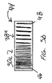
図3aは、中赤外線発生器22aの代替的な実施形態を提供している。この実施形態では、ポンプレーザー24aは、周波数変換器へ向けて任意選択的な入力結合器28aを通過してポンプレーザービーム26aを発している。ここでは、第1の光周波数変換器30aは、単一の結晶の形態で第2の光周波数変換器38aと結合されている。結晶の前部分は、第1の光周波数変換器30aを備えており、第2の部分は、第2の光周波数変換器38aを備えている。結合された結晶は、合わせて融合された2つの位相整合結晶又は疑似位相整合周期的分極結晶44で作ることが可能であり、図3bの概略図で示している。第1の光周波数変換器30aを形成している結晶44の部分は、一連の細いグリッド線46で図示されている。より太い且つより大きく間隔のあいたグリッド線48は、第2の光周波数変換器38aを形成している結晶44の部分を図示している。それらのグリッド線(46、48)は、周知の方法で形成される周期分極の位置を図示している。結晶44の第1の区分の分極は、ポンプをアイドラー及び信号(30a)に変換するように設計されているが、一方、結晶(38a)の第2の区分の分極は、信号をアイドラーに変換するように設計されている。
FIG. 3a provides an alternative embodiment of the mid-infrared generator 22a. In this embodiment, the pump laser 24a emits a pump laser beam 26a through an optional input coupler 28a towards the frequency converter. Here, the first optical frequency converter 30a is coupled to the second optical frequency converter 38a in the form of a single crystal. The front part of the crystal is provided with a first optical frequency converter 30a, and the second part is provided with a second optical frequency converter 38a. The combined crystal can be made of two phase matched crystals or quasi-phase matched periodically polarized crystals 44 fused together and is shown in the schematic of FIG. 3b. The portion of the crystal 44 that forms the first optical frequency converter 30 a is illustrated by a series of thin grid lines 46. The thicker and more spaced
中赤外線発生器22bの更に別の実施形態の概略図を図4aに示している。この実施形態では、ポンプレーザー24bは、任意選択的な入力結合器28bを通過するポンプレーザービーム26bを発しており、ポンプレーザービーム26bは、統合光周波数変換器50の中へ受け入れられる。統合光周波数変換器50は、第1及び第2の光周波数変換器(30、38)と本質的に同じ方法で作動し、本質的に同じ機能を果たす。統合光周波数変換器50は、更に、超音波レーザー試験ビームとして使用される出力波40bを発する。図4aの統合光周波数変換器50は、統合周期分極結晶52として図4bで概略的に描写されている。ここでは、細いグリッド線46a及び太いグリッド線48aは、結晶52の長さに沿って交互に並んでいる。
A schematic diagram of yet another embodiment of the mid-infrared generator 22b is shown in FIG. 4a. In this embodiment, the pump laser 24b emits a pump laser beam 26b that passes through an optional input coupler 28b, which is received into the integrated
中赤外線発生器の何れの実施形態で作られる最終波も、しかしながら、3.2ミクロンに制限されるものではなく、約3ミクロンから約4ミクロンまでを含むことができることに注目すべきである。本明細書における検討目的で、中赤外線範囲は、約3ミクロンから約4ミクロンまでの波長を有する波を画定する。 It should be noted that the final wave produced in any embodiment of the mid-infrared generator, however, is not limited to 3.2 microns and can include from about 3 microns to about 4 microns. For purposes herein, the mid-infrared range defines waves having a wavelength from about 3 microns to about 4 microns.
本明細書で説明される本発明は、従って、目的を遂行し、その中に本来備わっている他のものに加えて、言及した結果及び利点を獲得するようによく適合されるものである。本発明の現在好適な実施形態を開示目的で提示してきたが、所望の結果を達成する詳細な手順には多数の変更が存在する。それら及び他の類似の修正は、当業者であれば容易に想起されるであろうものであり、本明細書に開示する本発明の精神及び添付の特許請求の範囲の中に含まれるものと意図される。 The invention described herein is therefore well adapted to accomplish the objectives and obtain the results and advantages mentioned in addition to others inherent therein. While presently preferred embodiments of the invention have been presented for disclosure purposes, there are numerous changes in the detailed procedures for achieving the desired results. These and other similar modifications will be readily apparent to those skilled in the art and are intended to be included within the spirit of the invention and the appended claims as disclosed herein. Intended.
Claims (21)
放射波をポンプレーザー源から結晶の内部に設けられている第1の光変換器へ放射するステップであって、前記第1の光変換器は、前記放射波を信号波及びアイドラー波に変換し、前記アイドラー波の波長は、中赤外線範囲である、ステップと、
前記信号波及びアイドラー波を、前記第1の光変換器と共に結晶の内部に設けられている第2の光変換器へ方向付けるステップであって、前記第2の光変換器は、前記信号波の波長を中赤外線範囲に変換し、前記アイドラー波は、実質的には変化せずに前記第2の光変換器を通過し、及び前記アイドラー波は、単一の出力波を形成するように前記変換された信号波と結合する、ステップと、
検査対象を超音波検査するために、前記単一の出力波を検査対象の検査表面に放射するステップとを含み、
前記第1の光変換器は、前記第2の光変換器と合わせて融合することにより、該第2の光変換器と単一の統合周期分極結晶の形態で結合したものであることを特徴とする方法。 In the method of ultrasonic testing,
Radiating a radiation wave from a pump laser source to a first optical converter provided inside the crystal, wherein the first optical converter converts the radiation wave into a signal wave and an idler wave. The wavelength of the idler wave is in the mid-infrared range; and
Directing the signal wave and idler wave to a second optical converter provided inside the crystal together with the first optical converter, wherein the second optical converter includes the signal wave So that the idler wave passes through the second optical converter substantially unchanged and the idler wave forms a single output wave. Combining with the converted signal wave;
Radiating the single output wave to the inspection surface of the inspection object to ultrasonically inspect the inspection object;
The first optical converter is combined with the second optical converter to be combined with the second optical converter in the form of a single integrated periodic polarization crystal. And how to.
(a)結晶に対して、約1.064ミクロンの波長の入力レーザー波を放射するステップと、
(b)前記入力レーザー波を、約1.594ミクロンの波長を有する信号波と約3.2ミクロンの波長を有するアイドラー波に変換するステップと、
(c)前記結晶の別の部分において、前記信号波の波長を約3.2ミクロンの波長に変換するステップと、
(d)前記検査対象の検査表面に、前記アイドラー波及び波長が変換された前記信号波の混合波を放射することによって、該検査表面に超音波変位を生成するステップとを含み、
前記結晶における、前記入力レーザー波を前記信号波と前記アイドラー波とに変換する部分は、前記結晶における前記別の部分と合わせて融合することにより、該別の部分と単一の統合周期分極結晶の形態で結合したものであることを特徴とする方法。 In the method of ultrasonic testing the inspection object,
(A) emitting an input laser wave having a wavelength of about 1.064 microns to the crystal;
(B) converting the input laser wave into a signal wave having a wavelength of about 1.594 microns and an idler wave having a wavelength of about 3.2 microns;
(C) converting the wavelength of the signal wave to a wavelength of about 3.2 microns in another portion of the crystal;
(D) generating an ultrasonic displacement on the inspection surface by radiating a mixed wave of the signal wave whose wavelength is converted to the idler wave to the inspection surface to be inspected;
The portion of the crystal that converts the input laser wave into the signal wave and the idler wave is fused together with the other portion of the crystal, thereby combining the other portion with a single integrated periodically polarized crystal. A method characterized by being combined in the form of:
別のレーザー波を生成して、該レーザー波を振動している前記検査表面に放射するステップと、
前記検査表面の変位を検出するステップとを含んでいることを特徴とする方法。 The method of claim 12, further comprising:
Generating another laser wave and emitting the laser wave to the vibrating inspection surface;
Detecting the displacement of the inspection surface.
入力レーザー源と、
結晶と、
前記入力レーザー源からの入力レーザー波を信号波及びアイドラー波に変換する変換器であって、前記結晶内に配置される第1の光周波数変換器と、
前記結晶内に前記第1の光周波数変換器と統合して配置される第2の光周波数変換器であって、前記信号波の波長を前記アイドラー波と実質的に同じ波長に変換し、該変換された信号波及びアイドラー波を含む複合出力波であって、検査対象の対象表面上に超音波振動を発生するように、前記対象表面に方向付けることが可能である複合出力波を生成する第2の光周波数変換器と、
前記対象表面に方向付けることが可能であり且つ超音波変位を検出するように構成される検出レーザーとを備え、
前記第1の光変換器は、前記第2の光変換器と合わせて融合することにより、該第2の光変換器と単一の統合周期分極結晶の形態で結合したものであることを特徴とするレーザー超音波試験システム。 In the laser ultrasonic test system,
An input laser source;
Crystals,
A converter for converting an input laser wave from the input laser source into a signal wave and an idler wave, the first optical frequency converter disposed in the crystal;
A second optical frequency converter disposed in the crystal in an integrated manner with the first optical frequency converter, wherein the wavelength of the signal wave is converted to substantially the same wavelength as the idler wave, A composite output wave including the converted signal wave and idler wave, and generating a composite output wave that can be directed to the target surface to generate ultrasonic vibrations on the target surface to be inspected A second optical frequency converter;
A detection laser capable of directing to the target surface and configured to detect ultrasonic displacement;
The first optical converter is combined with the second optical converter to be combined with the second optical converter in the form of a single integrated periodic polarization crystal. Laser ultrasonic testing system.
Applications Claiming Priority (3)
| Application Number | Priority Date | Filing Date | Title |
|---|---|---|---|
| US12/120,823 US7821646B2 (en) | 2008-05-15 | 2008-05-15 | Method and apparatus for generating mid-IR laser beam for ultrasound inspection |
| US12/120,823 | 2008-05-15 | ||
| PCT/US2009/043893 WO2009140458A1 (en) | 2008-05-15 | 2009-05-14 | Method and apparatus for generating mid-ir laser for ultrasound inspection |
Publications (3)
| Publication Number | Publication Date |
|---|---|
| JP2011521230A JP2011521230A (en) | 2011-07-21 |
| JP2011521230A5 JP2011521230A5 (en) | 2012-05-31 |
| JP5520933B2 true JP5520933B2 (en) | 2014-06-11 |
Family
ID=40873363
Family Applications (1)
| Application Number | Title | Priority Date | Filing Date |
|---|---|---|---|
| JP2011509684A Expired - Fee Related JP5520933B2 (en) | 2008-05-15 | 2009-05-14 | Method and apparatus for generating a mid-infrared laser for use in ultrasonic inspection |
Country Status (11)
| Country | Link |
|---|---|
| US (1) | US7821646B2 (en) |
| EP (1) | EP2283340A1 (en) |
| JP (1) | JP5520933B2 (en) |
| KR (2) | KR20160075852A (en) |
| CN (2) | CN106226401A (en) |
| BR (1) | BRPI0912675A2 (en) |
| CA (1) | CA2724314C (en) |
| IL (1) | IL209291A (en) |
| SG (1) | SG10201609520XA (en) |
| TW (1) | TWI472758B (en) |
| WO (1) | WO2009140458A1 (en) |
Families Citing this family (7)
| Publication number | Priority date | Publication date | Assignee | Title |
|---|---|---|---|---|
| DE102009043700B4 (en) * | 2009-10-01 | 2013-11-07 | Eads Deutschland Gmbh | Laser ultrasonic measuring device |
| EP3115766A1 (en) | 2015-07-10 | 2017-01-11 | 3Scan Inc. | Spatial multiplexing of histological stains |
| JP6739836B2 (en) * | 2016-06-01 | 2020-08-12 | 国立研究開発法人物質・材料研究機構 | Laser and laser ultrasonic flaw detector using the same |
| CN105938087B (en) * | 2016-06-29 | 2018-10-30 | 华南理工大学 | A kind of laser ultrasonic detection system and method based on Multi-axis aircraft |
| JP2023115852A (en) * | 2022-02-08 | 2023-08-21 | 本田技研工業株式会社 | Vehicular headlight device |
| JP2023115856A (en) | 2022-02-08 | 2023-08-21 | 本田技研工業株式会社 | Vehicular headlight device |
| US20230375708A1 (en) * | 2022-05-17 | 2023-11-23 | Northrop Grumman Systems Corporation | Quantum lidar system |
Family Cites Families (35)
| Publication number | Priority date | Publication date | Assignee | Title |
|---|---|---|---|---|
| JPH0376802U (en) * | 1989-11-28 | 1991-08-01 | ||
| US5355247A (en) | 1993-03-30 | 1994-10-11 | The Board Of Trustees Of The Leland Stanford, Jr. University | Method using a monolithic crystalline material for producing radiation by quasi-phase-matching, diffusion bonded monolithic crystalline material for quasi-phase-matching, and method for fabricating same |
| US5400173A (en) | 1994-01-14 | 1995-03-21 | Northrop Grumman Corporation | Tunable mid-infrared wavelength converter using cascaded parametric oscillators |
| US5640405A (en) | 1996-02-01 | 1997-06-17 | Lighthouse Electronics Corporation | Multi quasi phase matched interactions in a non-linear crystal |
| JP3465478B2 (en) * | 1996-04-30 | 2003-11-10 | 理化学研究所 | Optical parametric oscillator |
| US5911389A (en) | 1996-12-20 | 1999-06-15 | Lockheed Martin Corp. | Wave based satellite constellation |
| US6050525A (en) | 1997-04-29 | 2000-04-18 | Lockheed Martin Corporation | Asymmetric open rosette constellations |
| US6094447A (en) | 1998-06-12 | 2000-07-25 | Lockheed Martin Corporation | System and method for reducing wavefront distortion in high-gain diode-pumped laser media |
| US6657733B1 (en) | 1998-06-30 | 2003-12-02 | Lockheed Martin Corporation | Method and apparatus for detecting ultrasonic surface displacements using post-collection optical amplification |
| US6633384B1 (en) | 1998-06-30 | 2003-10-14 | Lockheed Martin Corporation | Method and apparatus for ultrasonic laser testing |
| US6122060A (en) | 1998-06-30 | 2000-09-19 | Lockheed Martin Corporation | Method and apparatus for detecting ultrasonic surface displacements using post-collection optical amplification |
| US6016214A (en) | 1998-09-11 | 2000-01-18 | Northrop Grumman Corporation | Quadruple grating period PPLN optical parametric oscillator difference frequency generator with common doubly resonant cavity |
| WO2000020841A1 (en) * | 1998-10-05 | 2000-04-13 | Kla-Tencor Corporation | Interferometric system for measurement disturbance of a sample |
| US6483859B1 (en) | 1999-06-24 | 2002-11-19 | Lockheed Martin Corporation | System and method for high-speed laser detection of ultrasound |
| US7286241B2 (en) | 1999-06-24 | 2007-10-23 | Lockheed Martin Corporation | System and method for high-speed laser detection of ultrasound |
| US6335943B1 (en) | 1999-07-27 | 2002-01-01 | Lockheed Martin Corporation | System and method for ultrasonic laser testing using a laser source to generate ultrasound having a tunable wavelength |
| US6176135B1 (en) | 1999-07-27 | 2001-01-23 | Marc Dubois | System and method for laser-ultrasonic frequency control using optimal wavelength tuning |
| AU2002222955A1 (en) | 2000-07-14 | 2002-01-30 | Lockheed Martin Corporation | A system and method of determining porosity in composite materials using ultrasound |
| KR20030026972A (en) | 2000-07-14 | 2003-04-03 | 록히드 마틴 코포레이션 | System and method for locating and positioning an ultrasonic signal generator for testing purposes |
| US6937774B1 (en) | 2000-10-24 | 2005-08-30 | Lockheed Martin Corporation | Apparatus and method for efficiently increasing the spatial resolution of images |
| US6711954B2 (en) | 2001-01-19 | 2004-03-30 | Lockheed Martin Corporation | Method and apparatus for improving the dynamic range of laser detected ultrasound in attenuative materials |
| US6571633B1 (en) | 2001-01-19 | 2003-06-03 | Lockheed Martin Corporation | Remote laser beam delivery system and method for use with a gantry positioning system for ultrasonic testing purposes |
| JP2002228639A (en) * | 2001-01-30 | 2002-08-14 | Nippon Steel Corp | Apparatus and method for laser ultrasonic inspection |
| US6668654B2 (en) | 2001-08-15 | 2003-12-30 | Lockheed Martin Corporation | Method and apparatus for generating specific frequency response for ultrasound testing |
| US6606909B2 (en) | 2001-08-16 | 2003-08-19 | Lockheed Martin Corporation | Method and apparatus to conduct ultrasonic flaw detection for multi-layered structure |
| US6649900B2 (en) | 2001-09-07 | 2003-11-18 | Lockheed Martin Corporation | Photoreceiver assembly for high-powered lasers |
| US7117134B2 (en) | 2001-10-18 | 2006-10-03 | Lockheed Martin Corporation | Method to optimize generation of ultrasound using mathematical modeling for laser ultrasound inspection |
| JP4087098B2 (en) * | 2001-11-14 | 2008-05-14 | 株式会社東芝 | Ultrasonic inspection equipment |
| US6856918B2 (en) | 2001-11-26 | 2005-02-15 | Lockheed Martin Corporation | Method to characterize material using mathematical propagation models and ultrasonic signal |
| US6732587B2 (en) | 2002-02-06 | 2004-05-11 | Lockheed Martin Corporation | System and method for classification of defects in a manufactured object |
| US7277178B2 (en) | 2003-09-22 | 2007-10-02 | Celight, Inc. | Coherent photothermal interferometric spectroscopy system and method for chemical sensing |
| JP2006114642A (en) * | 2004-10-14 | 2006-04-27 | Tohoku Univ | Infrared coherent light source |
| US7184200B2 (en) | 2004-12-16 | 2007-02-27 | Lockheed Martin Corporation | Passive broadband infrared optical limiter device based on a micro-optomechanical cantilever array |
| US7369250B2 (en) | 2005-03-25 | 2008-05-06 | Lockheed Martin Corporation | System and method to inspect components having non-parallel surfaces |
| CN101089609A (en) * | 2007-06-28 | 2007-12-19 | 中国科学院安徽光学精密机械研究所 | Multiple spectral section continuous tuning high resolution infrared laser spectral measuring system and method |
-
2008
- 2008-05-15 US US12/120,823 patent/US7821646B2/en active Active
-
2009
- 2009-05-14 CA CA2724314A patent/CA2724314C/en not_active Expired - Fee Related
- 2009-05-14 SG SG10201609520XA patent/SG10201609520XA/en unknown
- 2009-05-14 KR KR1020167016289A patent/KR20160075852A/en not_active Application Discontinuation
- 2009-05-14 EP EP09747541A patent/EP2283340A1/en not_active Withdrawn
- 2009-05-14 CN CN201610702139.XA patent/CN106226401A/en active Pending
- 2009-05-14 KR KR1020107028047A patent/KR101662334B1/en active IP Right Grant
- 2009-05-14 CN CN2009801254642A patent/CN102089642A/en active Pending
- 2009-05-14 WO PCT/US2009/043893 patent/WO2009140458A1/en active Application Filing
- 2009-05-14 JP JP2011509684A patent/JP5520933B2/en not_active Expired - Fee Related
- 2009-05-14 BR BRPI0912675A patent/BRPI0912675A2/en not_active IP Right Cessation
- 2009-05-15 TW TW98116319A patent/TWI472758B/en not_active IP Right Cessation
-
2010
- 2010-11-14 IL IL209291A patent/IL209291A/en not_active IP Right Cessation
Also Published As
| Publication number | Publication date |
|---|---|
| CN102089642A (en) | 2011-06-08 |
| CA2724314A1 (en) | 2009-11-19 |
| AU2009246358A1 (en) | 2009-11-19 |
| CN106226401A (en) | 2016-12-14 |
| EP2283340A1 (en) | 2011-02-16 |
| JP2011521230A (en) | 2011-07-21 |
| KR20160075852A (en) | 2016-06-29 |
| TW200951433A (en) | 2009-12-16 |
| IL209291A (en) | 2013-03-24 |
| TWI472758B (en) | 2015-02-11 |
| KR101662334B1 (en) | 2016-10-04 |
| WO2009140458A1 (en) | 2009-11-19 |
| US20090284751A1 (en) | 2009-11-19 |
| US7821646B2 (en) | 2010-10-26 |
| SG10201609520XA (en) | 2016-12-29 |
| IL209291A0 (en) | 2011-01-31 |
| KR20110010111A (en) | 2011-01-31 |
| BRPI0912675A2 (en) | 2016-01-26 |
| CA2724314C (en) | 2013-11-26 |
Similar Documents
| Publication | Publication Date | Title |
|---|---|---|
| JP5520933B2 (en) | Method and apparatus for generating a mid-infrared laser for use in ultrasonic inspection | |
| JP5951673B2 (en) | Improved mid-infrared laser for generating ultrasound using a CO2 laser and harmonic generation | |
| JP2011521230A5 (en) | ||
| JP5396671B2 (en) | Improved mid-infrared laser for generating ultrasound | |
| JP2011521233A5 (en) | ||
| AU2009246358B2 (en) | Method and apparatus for generating mid-IR laser for ultrasound inspection | |
| AU2009246278B2 (en) | Improved mid-IR laser for generation of ultrasound | |
| JP2021110555A (en) | Noncontact oscillation measurement device and noncontact oscillation measurement method |
Legal Events
| Date | Code | Title | Description |
|---|---|---|---|
| A521 | Request for written amendment filed |
Free format text: JAPANESE INTERMEDIATE CODE: A523 Effective date: 20110119 |
|
| A621 | Written request for application examination |
Free format text: JAPANESE INTERMEDIATE CODE: A621 Effective date: 20111202 |
|
| A521 | Request for written amendment filed |
Free format text: JAPANESE INTERMEDIATE CODE: A523 Effective date: 20120403 |
|
| A131 | Notification of reasons for refusal |
Free format text: JAPANESE INTERMEDIATE CODE: A131 Effective date: 20130802 |
|
| RD02 | Notification of acceptance of power of attorney |
Free format text: JAPANESE INTERMEDIATE CODE: A7422 Effective date: 20131003 |
|
| RD03 | Notification of appointment of power of attorney |
Free format text: JAPANESE INTERMEDIATE CODE: A7423 Effective date: 20131003 |
|
| RD04 | Notification of resignation of power of attorney |
Free format text: JAPANESE INTERMEDIATE CODE: A7424 Effective date: 20131009 |
|
| A601 | Written request for extension of time |
Free format text: JAPANESE INTERMEDIATE CODE: A601 Effective date: 20131101 |
|
| A602 | Written permission of extension of time |
Free format text: JAPANESE INTERMEDIATE CODE: A602 Effective date: 20131111 |
|
| A521 | Request for written amendment filed |
Free format text: JAPANESE INTERMEDIATE CODE: A523 Effective date: 20131112 |
|
| A131 | Notification of reasons for refusal |
Free format text: JAPANESE INTERMEDIATE CODE: A131 Effective date: 20131210 |
|
| A521 | Request for written amendment filed |
Free format text: JAPANESE INTERMEDIATE CODE: A523 Effective date: 20140227 |
|
| TRDD | Decision of grant or rejection written | ||
| A01 | Written decision to grant a patent or to grant a registration (utility model) |
Free format text: JAPANESE INTERMEDIATE CODE: A01 Effective date: 20140325 |
|
| A61 | First payment of annual fees (during grant procedure) |
Free format text: JAPANESE INTERMEDIATE CODE: A61 Effective date: 20140407 |
|
| R150 | Certificate of patent or registration of utility model |
Ref document number: 5520933 Country of ref document: JP Free format text: JAPANESE INTERMEDIATE CODE: R150 |
|
| LAPS | Cancellation because of no payment of annual fees |