JP5520378B2 - Apparatus and method for aligning two medical images - Google Patents
Apparatus and method for aligning two medical images Download PDFInfo
- Publication number
- JP5520378B2 JP5520378B2 JP2012523378A JP2012523378A JP5520378B2 JP 5520378 B2 JP5520378 B2 JP 5520378B2 JP 2012523378 A JP2012523378 A JP 2012523378A JP 2012523378 A JP2012523378 A JP 2012523378A JP 5520378 B2 JP5520378 B2 JP 5520378B2
- Authority
- JP
- Japan
- Prior art keywords
- image
- model
- alignment
- geometric model
- organ
- Prior art date
- Legal status (The legal status is an assumption and is not a legal conclusion. Google has not performed a legal analysis and makes no representation as to the accuracy of the status listed.)
- Expired - Fee Related
Links
Images


Classifications
-
- G—PHYSICS
- G06—COMPUTING; CALCULATING OR COUNTING
- G06T—IMAGE DATA PROCESSING OR GENERATION, IN GENERAL
- G06T7/00—Image analysis
- G06T7/30—Determination of transform parameters for the alignment of images, i.e. image registration
- G06T7/33—Determination of transform parameters for the alignment of images, i.e. image registration using feature-based methods
- G06T7/344—Determination of transform parameters for the alignment of images, i.e. image registration using feature-based methods involving models
-
- G—PHYSICS
- G06—COMPUTING; CALCULATING OR COUNTING
- G06T—IMAGE DATA PROCESSING OR GENERATION, IN GENERAL
- G06T7/00—Image analysis
- G06T7/30—Determination of transform parameters for the alignment of images, i.e. image registration
- G06T7/35—Determination of transform parameters for the alignment of images, i.e. image registration using statistical methods
-
- G—PHYSICS
- G06—COMPUTING; CALCULATING OR COUNTING
- G06T—IMAGE DATA PROCESSING OR GENERATION, IN GENERAL
- G06T2207/00—Indexing scheme for image analysis or image enhancement
- G06T2207/10—Image acquisition modality
- G06T2207/10072—Tomographic images
- G06T2207/10081—Computed x-ray tomography [CT]
-
- G—PHYSICS
- G06—COMPUTING; CALCULATING OR COUNTING
- G06T—IMAGE DATA PROCESSING OR GENERATION, IN GENERAL
- G06T2207/00—Indexing scheme for image analysis or image enhancement
- G06T2207/10—Image acquisition modality
- G06T2207/10072—Tomographic images
- G06T2207/10088—Magnetic resonance imaging [MRI]
-
- G—PHYSICS
- G06—COMPUTING; CALCULATING OR COUNTING
- G06T—IMAGE DATA PROCESSING OR GENERATION, IN GENERAL
- G06T2207/00—Indexing scheme for image analysis or image enhancement
- G06T2207/10—Image acquisition modality
- G06T2207/10132—Ultrasound image
- G06T2207/10136—3D ultrasound image
-
- G—PHYSICS
- G06—COMPUTING; CALCULATING OR COUNTING
- G06T—IMAGE DATA PROCESSING OR GENERATION, IN GENERAL
- G06T2207/00—Indexing scheme for image analysis or image enhancement
- G06T2207/30—Subject of image; Context of image processing
- G06T2207/30004—Biomedical image processing
-
- G—PHYSICS
- G06—COMPUTING; CALCULATING OR COUNTING
- G06T—IMAGE DATA PROCESSING OR GENERATION, IN GENERAL
- G06T2207/00—Indexing scheme for image analysis or image enhancement
- G06T2207/30—Subject of image; Context of image processing
- G06T2207/30004—Biomedical image processing
- G06T2207/30081—Prostate
Description
本発明は、2つの医用画像を互いに位置合わせすることに関し、特に2つの画像が、異なる撮像技術で得られた場合の位置合わせに関する。 The present invention relates to aligning two medical images with each other, and in particular to alignment when the two images are obtained with different imaging techniques.
磁気共鳴(magnetic resonance、以下MR)撮像、X線コンピュータ断層撮影(computed tomography、以下CT)、放射性核種撮像、光学的撮像、および超音波など、様々な医療用撮像技術が知られている。将来、他の撮像技術も開発される可能性がある。これらの撮像技術では、二次元(2D)配列のピクセル(従来画像)または三次元(3D)配列のボクセルを作り、対象物のあらゆる断面を概念的に表示する。各ピクセルまたはボクセルには、組織の特定の点の1つ以上の物理的特性に関連し、使用する特定の撮像方法に特有の値すなわち「強度」が割り当てられる。本明細書で使用される「画像」の用語は、文中に特に断りがない限り、2Dデータ組および3Dデータ組の両方を包含する。 Various medical imaging techniques are known, such as magnetic resonance (MR) imaging, X-ray computed tomography (CT), radionuclide imaging, optical imaging, and ultrasound. Other imaging technologies may be developed in the future. In these imaging techniques, a two-dimensional (2D) array of pixels (conventional image) or a three-dimensional (3D) array of voxels is created to conceptually display any cross section of the object. Each pixel or voxel is assigned a value or “intensity” that is associated with one or more physical characteristics of a particular point of tissue and is specific to the particular imaging method used. As used herein, the term “image” encompasses both 2D and 3D data sets, unless otherwise specified in the text.
場合により、同一の人体領域ではあるが異なる撮像技術によって得られた画像を整列させるなど、多様な画像を位置合わせできることが望ましい。これは多くの場合非常に難しい。というのは異なる撮像技術を用いて得られた画像の間には強度特性の大きな違いがあるためである。また、各撮像方法に特有の基本となる物理学および画像生成過程間の根本的な違いにより、撮像方式に固有のアーチファクト(不自然な結果=artifact)を生じることもある。さらに問題になるのは、人体の軟らかい組織臓器のほぼ全てを含む変形しやすい構造のため、隣接する構造に対する物理的な変形および動きが、撮像と撮像の間に生じる場合があることである。これらの影響が画像位置合わせの問題をさらに複雑にする。 In some cases, it is desirable to be able to align various images, such as aligning images obtained by different imaging techniques in the same human body region. This is often very difficult. This is because there is a large difference in intensity characteristics between images obtained using different imaging techniques. Also, fundamental differences between the imaging physics and image generation processes that are unique to each imaging method may cause artifacts (unnatural results = artifacts) that are specific to the imaging method. A further problem is that due to the deformable structure including almost all of the soft tissue organs of the human body, physical deformation and movement of adjacent structures may occur between imaging. These effects further complicate the image registration problem.
画像を位置合わせするよく知られたやり方の1つに、情報の論理的類似度を最大にしようとする方法などの、いわゆる強度基準アルゴリズムがある。これらの技法では、ある画像の強度と他の画像の対応する領域の強度との間の確率的関係を暗黙的に仮定して、ある強度地図を他の強度地図に書き換える。しかし多くの場合この仮定は、同じ解剖学的領域の画像を得るために異なる物理特性を利用する別の撮像方法が用いられる状況では信頼性がない。 One well-known way of registering images is a so-called intensity criterion algorithm, such as a method that attempts to maximize the logical similarity of information. These techniques rewrite one intensity map to another intensity map implicitly assuming a stochastic relationship between the intensity of one image and the intensity of the corresponding region of another image. However, in many cases this assumption is unreliable in situations where another imaging method is used that utilizes different physical properties to obtain an image of the same anatomical region.
一般に特徴基準位置合わせと呼ばれる別の手法では、入力画像は最初に単純な幾何学的表現(点または面の組など)に分解され、次にこれらの幾何学的表現が互いに位置合わせされる。一般にこのやり方は、各画像内の解剖学的目標点、組織境界など、対応する特徴を識別する。画像分割として知られている画像データから特徴を抽出する過程は分割ソフトウエアを用いて実行することができ、場合によっては使用者が全くあるいはほとんど操作しない場合がある。しかし他の多くの場合、分割は専門の監視者が手作業で実施しなければならない。したがってこの特徴基準の位置合わせ手法は、市販のコンピュータ自動分割法が手に入らないまたはうまく機能しない、または少なくとも1つの画像の手動分割に非常に時間と手間が掛かるならば、多くの場合現実的ではない。 In another approach, commonly referred to as feature-based registration, the input image is first decomposed into a simple geometric representation (such as a set of points or faces) and then these geometric representations are aligned with each other. In general, this approach identifies corresponding features such as anatomical target points and tissue boundaries in each image. The process of extracting features from image data, known as image segmentation, can be performed using segmentation software, and in some cases, the user may perform no or little manipulation. However, in many other cases, the division must be performed manually by a specialized observer. Therefore, this feature-based registration technique is often practical if a commercially available computer automatic segmentation method is not available or does not work well, or if manual segmentation of at least one image is very time consuming and laborious. is not.
特徴基準画像位置合わせへの依存は、速度重視の用途、例えば画像に誘導される手術などでは特に問題である。というのは、このような手術中に得られる画像は手術環境外で得られる画像よりも一般に画質が悪いためである。したがってこれらの画像を、自動的にすなわち臨床的に許容できる時間(すなわち数秒から数分)内に分割することは大抵の場合非常に困難である。 Dependence on feature reference image alignment is particularly problematic in speed-sensitive applications such as image-guided surgery. This is because images obtained during such surgery generally have poorer image quality than images obtained outside the surgical environment. Therefore, it is often very difficult to segment these images automatically, i.e. within a clinically acceptable time (i.e. a few seconds to a few minutes).
超音波撮像は、安全、非浸襲、安価、搬送可能、および病院内で広く利用できることから、日常的に使用されて広範囲の医療手術中にリアルタイムで手術を誘導できるようにしている。しかし現在、超音波画像を他の種類の画像と正確に位置合わせして、診断品質の画像(特にMRおよびX線CT画像)から得られる解剖学的情報および病理学的情報で超音波画像を視覚的に補強することによって、多くの手術を正確に誘導できるようにする多様画像位置合わせ方法の臨床的要求が高まっている。そのような情報には、手術中に得られる超音波画像では見えない(例えば、可視化が不十分または画像の視野外にある)病変(例えば癌性腫瘍)または臓器の位置、または特に疾患診断のために得た画像から得られた情報を用いて決められた治療計画または生検試料採取計画の表示、または他の情報源からの診断情報と組み合わせた手術計画の表示がある。 Because ultrasound imaging is safe, non-invasive, inexpensive, transportable, and widely available in hospitals, it is routinely used to allow surgery to be guided in real time during a wide range of medical procedures. Currently, however, the ultrasound image is accurately aligned with other types of images and the anatomical and pathological information obtained from diagnostic quality images (especially MR and X-ray CT images). There is an increasing clinical need for a multi-image registration method that, by visual reinforcement, can accurately guide many operations. Such information includes lesions (eg, cancerous tumors) or organ locations that are invisible (eg, poorly visualized or outside the field of view of the image) or organs, or in particular for disease diagnosis, obtained during surgery. There is a display of treatment plans or biopsy sampling plans determined using information obtained from the acquired images, or a surgical plan combined with diagnostic information from other sources.
多様画像位置合わせが正確に実施できれば、例えばMR画像内に確認された腫瘍の位置を、手術器具を誘導する目的で外科手術中に普通に得られた超音波画像に重ねて表示することができる。この方法は、手術器具の現在位置に対する相対的な腫瘍位置に関する視覚情報を提供することによって医師を支援するため、組織生検試料を正確な位置から採取して診断を確定することができ、または腫瘍を治療するための介入を十分正確に実施して、腫瘍および所定の外科的余裕を含む領域内の組織を破壊または除去することができる。しかし、診断画像情報が術中画像と正確に一致していなければ、誤差を生じて診断試験としての生検の精度を制限する、または介入の臨床的有効性を著しく制限することがある。現実には、このような誤差には、生検針の配置誤差、腫瘍周囲の組織の適切な余裕を除去できず悪性癌細胞を臓器から完全に除去できない、健全な組織をいたずらに損傷しその手術に関連する副作用の危険性を高めるということが含まれる。 If multi-image alignment can be performed accurately, for example, the position of a tumor identified in an MR image can be displayed superimposed on an ultrasound image normally obtained during surgery for the purpose of guiding a surgical instrument. . This method assists the physician by providing visual information about the tumor location relative to the current location of the surgical instrument, so that a tissue biopsy sample can be taken from the correct location to confirm the diagnosis, or Interventions to treat the tumor can be performed sufficiently accurately to destroy or remove the tissue in the area containing the tumor and a predetermined surgical margin. However, if the diagnostic image information does not exactly match the intraoperative image, an error may occur that limits the accuracy of the biopsy as a diagnostic test or significantly limits the clinical effectiveness of the intervention. In reality, such errors include biopsy needle placement errors, the proper margin of tissue surrounding the tumor cannot be removed, and malignant cancer cells cannot be completely removed from the organ, and the healthy tissue is mischievously damaged and operated. This includes increasing the risk of side effects associated with.
残念ながら、標準の強度基準の多様画像位置合わせアルゴリズムは、超音波画像と一緒では成績が良くないことが知られている。その理由は主に、雑音レベルが大きい、軟らかい組織の明暗差が比較的悪い、一般に医用超音波画像にはアーチファクトがあることである。さらに同じ理由から画像分割が困難であり、したがって多くの特徴基準像位置合わせ手法はほとんどの臨床用途では使用されない。 Unfortunately, standard intensity-based multi-image registration algorithms are known not to perform well with ultrasound images. This is mainly due to the presence of artifacts in medical ultrasound images, typically with high noise levels and relatively poor contrast between soft tissues. Furthermore, image segmentation is difficult for the same reason, so many feature-based image registration techniques are not used in most clinical applications.
何名かの著者が複合位置合わせ技法を研究してきており、表面対画像位置合わせ、特徴対画像位置合わせ、モデル対画像位置合わせ、またはモデル対ピクセル位置合わせなど種々の技法が知られている。この手法では、従来の特徴基準の手法と同じ方法で、参照画像を分割して表面境界、管状構造などの特徴を抽出することによって、関心のある臓器の幾何学的表示を発生させる。しかし特徴基準の方法と異なり、これらの特徴を、明確には分割されていないが何らかの方法、例えば境界などの特徴を強調する方法で処理することができる第2の画像のピクセル/ボクセル強度値に直接一致させる。この処理は普通、第1の画像の特徴と第2の画像の強度値とを最適に揃える変形を決定する数学的費用関数を最小化することによって実現される。 Several authors have studied composite registration techniques, and various techniques are known, such as surface-to-image registration, feature-to-image registration, model-to-image registration, or model-to-pixel registration. In this method, a geometric display of the organ of interest is generated by extracting features such as surface boundaries and tubular structures by dividing the reference image in the same manner as the conventional feature criterion method. However, unlike the feature-based method, these features are converted into pixel / voxel intensity values in the second image that are not clearly divided but can be processed in some way, such as enhancing the features such as boundaries. Match directly. This process is usually accomplished by minimizing a mathematical cost function that determines the deformation that optimally aligns the features of the first image and the intensity values of the second image.
上記技法の最も広範に検討された例は、非特許文献4(Cootes等、1995年)のいわゆる動的形状モデルである。この方法では、幾何学的モデルが統計的形状モデルとして表され、見えない画像内の対象の境界に適合するまで変形を繰り返す。密接に関連した方法がいわゆる動的見え方モデルであり、非特許文献5(Cootes等、1998年)および非特許文献3(Beichel等、2005年)を参照されたい。この方法では、統計的形状モデルの表面の局所領域における画像強度(すなわち見え方)の統計的変動が、学習フェーズのモデルに取り入れられる。次にこの情報を用いて形状モデルを見えない画像の対象境界に一致させる。この一致は、変形する境界上の点の周りの画像の局所強度特性と、動的見え方モデルによって学習された対応する強度変動と間の類似性の度合いを最大化させることによって行われる。このような度合いの1つは差分二乗和である。動的形状モデルおよび動的見え方モデルは共に、コンピュータビジョンおよび医療用撮像、具体的には画像分類、画像分割、および画像位置合わせの広範な画像解析問題にうまく適用されている。しかし、2つの方法は、対象の境界が隠れている、または見えない画像の強度特性がモデルを学習させるのに使用される画像と大きく異なるなど、見えない画像に何らかの問題がある場合はうまく機能しないことが知られている。この状況は、医用画像アプリケーションでは非常に一般的であり、特に、介入中に得られた(見えない)画像にいつも通り雑音が多く、アーチファクトがあり、医療器具が患者に挿入されている画像誘導による介入中は非常に一般的である。また、雑音、アーチファクト、および患者間のばらつきのせいで、相応しい寸法にした学習画像組内の対象の境界上の点の周りの画像強度の変動が大きすぎて、有意義なパラメータ統計尺度を決定することができない状況も多数ある。この場合、動的見え方モデル法の仮定は崩れる場合がある。 The most widely studied example of the above technique is the so-called dynamic shape model of Non-Patent Document 4 (Cootes et al., 1995). In this method, the geometric model is represented as a statistical shape model, and the deformation is repeated until it matches the boundary of the object in the invisible image. A closely related method is the so-called dynamic appearance model, see Non-Patent Document 5 (Cootes et al., 1998) and Non-Patent Document 3 (Beichel et al., 2005). In this method, statistical variations in image intensity (ie, appearance) in local regions on the surface of the statistical shape model are incorporated into the learning phase model. This information is then used to match the shape model to the target boundary of the invisible image. This matching is done by maximizing the degree of similarity between the local intensity characteristics of the image around the point on the deforming boundary and the corresponding intensity variation learned by the dynamic appearance model. One such degree is the sum of squared differences. Both the dynamic shape model and the dynamic appearance model have been successfully applied to a wide range of image analysis problems of computer vision and medical imaging, specifically image classification, image segmentation, and image registration. However, the two methods work well if there are any problems with the invisible image, such as when the boundary of the object is hidden or the intensity characteristics of the invisible image differ significantly from the image used to train the model It is known not to. This situation is very common in medical imaging applications, especially image guidance where the images obtained during the intervention (invisible) are noisy, have artifacts and the medical device is inserted into the patient It is very common during intervention by. Also, due to noise, artifacts, and patient-to-patient variation, the variation in image intensity around points on the subject's boundary in the appropriately sized learning image set is too great to determine a meaningful parameter statistic measure There are many situations where this is not possible. In this case, the assumption of the dynamic appearance model method may be broken.
非特許文献18(Shao等、2006年)には上記技法の一例の説明があり、恥骨弓のMR画像を経直腸的超音波プローブによって得られた超音波画像と整列している。この技法ではMR画像内の骨表面を手作業で識別する。次に、領域の強度が高いまたは画像強度に勾配があるなどの画像特性を基に、剛体変換が特定されてこの表面を超音波画像と揃えている。 Non-patent document 18 (Shao et al., 2006) describes an example of the above technique, which aligns the MR image of the pubic arch with the ultrasound image obtained by a transrectal ultrasound probe. This technique manually identifies the bone surface in the MR image. Next, based on image characteristics such as high region intensity or gradient in image intensity, a rigid transformation is identified and the surface is aligned with the ultrasound image.
非特許文献2(Aylward等、2003年)は、血管画像の位置合わせおよび解析のためのモデル対画像手法が説明されている。この方法は中心線追跡を用いてMR画像などの第1の画像から血管網のモデルを構築する。次に、モデル内の中心線の点が画像の輝線に対応すると仮定して、このモデルを剛体変換して超音波画像などの第2の画像と揃える。非特許文献2の著者は、非剛体変換がこの手法に及ぼす影響の検討を進めている。 Non-Patent Document 2 (Aylward et al., 2003) describes a model-to-image technique for registration and analysis of blood vessel images. This method constructs a model of a vascular network from a first image such as an MR image using centerline tracking. Next, assuming that the center line point in the model corresponds to the bright line of the image, the model is rigidly transformed and aligned with a second image such as an ultrasound image. The author of Non-Patent Document 2 is examining the effect of non-rigid transformation on this technique.
非特許文献21(Wu、R.等、2003年)には、前立腺生検用のモデル対ピクセル位置合わせ手法についての説明がある。著者等は、前立腺境界の統計的モデル上で作動する遺伝的アルゴリズム(GA)を使用して前立腺用の2D境界の母集団を展開し、その後超音波画像からの勾配地図と一致させている。GA内の各候補(個々の2D境界)は特定の剛体変換に対応し、超音波勾配画像と一致すればするほど境界個々の適合性は高くなる。個々の境界にも、変形(非剛体変換)させるためのパラメータを含められないか、あるいは代わりにこのような変形を、最適な剛体位置合わせに最終段階として追加できないか検討されている。 Non-Patent Document 21 (Wu, R. et al., 2003) describes a model-to-pixel alignment technique for prostate biopsy. The authors have developed a population of 2D boundaries for the prostate using a genetic algorithm (GA) that operates on a statistical model of the prostate boundary and then matched it with a gradient map from the ultrasound image. Each candidate (individual 2D boundary) in the GA corresponds to a specific rigid body transformation, and the more consistent with the ultrasonic gradient image, the higher the suitability of each boundary. It is being considered whether individual boundaries may not include parameters for deforming (non-rigid transformation), or alternatively such deformations can be added as a final step to optimal rigid alignment.
非特許文献10(King等、2001年)には、肝臓治療のための術前MR画像またはCT画像の術中超音波画像との位置合わせについての説明がある。統計的形状モデルを分割複数MR走査によって得て、変動の平均表面形状およびモードを決定している。次に変動のモードを呼吸周期に起因する変化を表す単一パラメータに限定する。次にこのモデルを、(i)剛体変換および(ii)呼吸による臓器変形を表す非剛体変換の方法によって超音波画像に位置決めする。(変換された)モデル表面全体の画像強度の加算を基にこの位置合わせを実施するために、確率論的(ベイズ)モデルが用いられる。 Non-Patent Document 10 (King et al., 2001) describes the alignment of a preoperative MR image or CT image with an intraoperative ultrasound image for liver treatment. A statistical shape model is obtained by split multiple MR scans to determine the average surface shape and mode of variation. The mode of variation is then limited to a single parameter representing the change due to the respiratory cycle. The model is then positioned in the ultrasound image by methods of (i) rigid transformation and (ii) non-rigid transformation representing organ deformation due to respiration. A stochastic (Bayesian) model is used to perform this alignment based on the addition of image intensity across the (transformed) model surface.
超音波基準位置合わせに対する他の取り組みが提案されてきており、特に非特許文献17(Roche等、2001年)、15(Penny等、2004年)、16(Penny等、2006年)、23(Zhang等、2007年)、20(Wein等、2008年)を参照されたい。しかし現在まで、これらが実証されているのはわずかの臓器および特殊な応用例についてだけであり、これらは、少なくとも1つの画像を、確立した強度基準法を用いる位置合わせを行って、さらに適した形状に自動的に変換することによっている。しかし、この変換手順は多くの場合に自明ではなく、今後これら代替手法を、前立腺の画像誘導による針生検および前立腺癌治療のための画像誘導による外科的介入など、多数の医学的に重要な応用例に対して実証する必要がある。 Other approaches to ultrasonic reference alignment have been proposed, especially Non-Patent Literature 17 (Roche et al., 2001), 15 (Penny et al., 2004), 16 (Penny et al., 2006), 23 (Zhang Et al., 2007), 20 (Wein et al., 2008). To date, however, these have only been demonstrated for a few organs and special applications, which are more suitable by aligning at least one image with an established intensity reference method. By automatically converting to shape. However, this conversion procedure is not obvious in many cases, and in the future these alternative approaches will be used in many medically important applications, such as prostate-guided needle biopsy and image-guided surgical intervention for prostate cancer treatment. It needs to be demonstrated against examples.
特許文献1(米国特許出願公開2003/015611)では、中間原子いわゆる「中間表現」(medial representation)を用いて表現された幾何学的モデルが説明されている。中間表現表面の領域内で計算された局所中間強度基準類似度を数値的に最適化することによって、中間表現を画像に位置合わせする方法が説明されている。 Patent Document 1 (U.S. Patent Application Publication No. 2003/015611) describes a geometric model expressed using intermediate atoms, so-called “intermediate representations”. A method is described for aligning an intermediate representation to an image by numerically optimizing the local intermediate intensity reference similarity calculated within the region of the intermediate representation surface.
特許文献2(WO2009/052497)にもまた、中間表現に注目し、一つの画像から得た臓器の中間表現モデルを第2の画像に非剛体位置合わせする方法が説明されている。上記のように、代表的な状況は、外科的介入の計画に用いる画像からモデルを入手する一方、第2の(対象)画像をその介入の最中に得るため、関心のある臓器がそれら画像を得る時間の間に変形してしまっているという時である。軟かい組織の変形を予測するために、より具体的には統計的形状モデル用の学習データを提供するために、有限要素モデル化が用いられる。モデル対画像法は、上記概説した動的見え方モデル化に基づいている。モデル境界の局所領域の画像強度の統計的ばらつきを、主成分解析を適用して、従来の動的見え方モデルと同様に線形形式で表し、次にこの情報を用いてモデル表面を対象画像に適合させる。しかしこの手法は、異なる学習画像全域の対応する位置における強度変動がガウス分布に従うと仮定しており、これは特に介入画像には当てはまらない場合がある。 Patent Document 2 (WO2009 / 052497) also describes a method of focusing an intermediate representation and non-rigidly aligning an intermediate representation model of an organ obtained from one image with a second image. As noted above, a typical situation is that a model is obtained from an image used to plan a surgical intervention, while a second (subject) image is obtained during the intervention so that the organ of interest is in the image. It is a time that has been transformed during the time to get. Finite element modeling is used to predict soft tissue deformation, more specifically to provide learning data for a statistical shape model. The model-to-image method is based on the dynamic appearance modeling outlined above. Statistical variation of the image intensity in the local region of the model boundary is expressed in a linear form as in the conventional dynamic appearance model by applying principal component analysis, and then this information is used to convert the model surface into the target image. Adapt. However, this approach assumes that intensity variations at corresponding positions across different learning images follow a Gaussian distribution, which may not be particularly true for interventional images.
医用画像位置合わせ用の、臓器の動きの種々の計算モデルが提案されてきた。例えば特許文献3(WO2003/107275)は、呼吸および心臓の動きによる臓器の動きの生理学的モデルを使用して2つの画像内の臓器の間の変形を予測し、次にこの2つの画像を、PET画像とCT画像との位置合わせの問題に注目して、非剛体的に位置合わせすることを説明している。検討された動きモデルは、臓器表面の非一様有理Bスプライン(NURB)表示を変形させることに基づいており、統計的なものではない。幾何学的モデルは位置合わせされる両画像を分割することによって作られ、外科アプリケーションには問題がある可能性がある。 Various computational models of organ motion have been proposed for medical image registration. For example, Patent Document 3 (WO2003 / 107275) uses a physiological model of organ motion due to respiration and heart motion to predict deformation between organs in two images, and then uses the two images as Focusing on the problem of alignment between the PET image and the CT image, the non-rigid alignment is described. The motion model considered is based on deforming the non-uniform rational B-spline (NURB) representation of the organ surface and is not statistical. Geometric models are created by splitting both images that are to be registered, which can be problematic for surgical applications.
特許文献4(WO2007/133932)には、放射線治療用の医用画像の変形可能な位置合わせの方法が開示されている。ここでも全ての入力画像を分割しなければならない。この手法の場合、(直にモデル対画像位置合わせを実施するのではなく)位置合わせの前に画像内で目標を決定する。 Patent Document 4 (WO2007 / 133932) discloses a deformable alignment method for medical images for radiation therapy. Again, all input images must be split. In this approach, a target is determined in the image prior to registration (rather than performing model-to-image registration directly).
より一般的な変形可能な画像位置合わせ法が特許文献5(WO2008/041125)に開示されている。この方法では、画像の異なる部分(例えば、異なる組織の種類または組織境界の間の機械的な不連続性に対応する)の非剛体挙動の変動を、空間的に変化する「柔軟性」および/または位置合わせ中に適用される非ガウス平滑化によって説明することができる。 A more general deformable image registration method is disclosed in Patent Document 5 (WO2008 / 041125). In this method, variations in the non-rigid behavior of different parts of the image (eg, corresponding to mechanical discontinuities between different tissue types or tissue boundaries) can be spatially changed, “flexibility” and / or Or it can be explained by non-Gaussian smoothing applied during alignment.
前立腺癌は世界的に重大な健康問題であり、特に西欧諸国の男性に影響を与えている。標準的治療方法には、例えば外科的切除または放射線治療による前立腺全体の根治治療、または積極的監視/注意観察プログラムの継続があり、後者では疾患進行の兆候がないか患者を観察することに熱心になるあまり介入が遅れてしまう。前立腺癌に対する別の低浸襲介入、例えば小線源療法、凍結療法、高密度焦点式超音波、高周波焼灼、光線力学的治療なども現在利用できるが、これら治療手法は、今後その臨床的有効性を無作為対照試験でさらに完全に確立する必要があるものばかりである。 Prostate cancer is a serious health problem worldwide, particularly affecting men in Western countries. Standard treatment methods include radical treatment of the entire prostate, for example, by surgical excision or radiation therapy, or continuation of an active monitoring / attention program, with the latter dedicated to observing the patient for signs of disease progression Intervention is delayed so much. Other low-invasive interventions for prostate cancer, such as brachytherapy, cryotherapy, high-intensity focused ultrasound, radiofrequency ablation, and photodynamic therapy, are currently available, but these treatment methods will be clinically effective in the future. Only those that need to be more fully established in a randomized controlled trial.
前立腺癌治療を受けた患者の70%までが、膀胱、直腸、および/または神経血管束の損傷に起因する長期の副作用、主に性機能障害および失禁に悩む。従来治療に較べて副作用の危険性が減る可能性に動機付けられて、前立腺癌の標的治療を可能にする技法への関心が、傷つきやすい構造体への損傷を最小にしようという取り組みの中で、近年高まっている(非特許文献1(Ahmed等、2008年))。これが、前立腺の(全体ではなく)少部分を治療する「局所治療」など、代替治療法への関心に繋がってきた。この技法が治療の治療効果に妥協することなく副作用の大きな低減に繋がることが、臨床的擁護者から期待されている。治療時の治療費用も低減され、入院もずっと短期になるはずである。しかしこのような標的治療手法は、針生検を用いて得られた組織試料の組織学的分析、およびMR撮像に基づく癌の正確な3Dマッピングに依存している。 Up to 70% of patients treated for prostate cancer suffer from long-term side effects, primarily sexual dysfunction and incontinence, resulting from damage to the bladder, rectum, and / or neurovascular bundles. Motivated by the potential to reduce the risk of side effects compared to conventional treatment, interest in techniques that enable targeted treatment of prostate cancer is in an effort to minimize damage to sensitive structures Recently, it is increasing (Non-Patent Document 1 (Ahmed et al., 2008)). This has led to interest in alternative therapies, such as “local treatment” that treats a small portion of the prostate (not the whole). It is expected by clinical advocates that this technique will lead to a significant reduction in side effects without compromising the therapeutic effect of the treatment. Treatment costs at the time of treatment should be reduced and hospitalization should be much shorter. However, such targeted therapy approaches rely on histological analysis of tissue samples obtained using needle biopsy and accurate 3D mapping of cancer based on MR imaging.
経直腸的超音波撮像は現在も、前立腺治療のための誘導針生検および治療的介入に最も利用しやすく実際的な手段である。しかし、従来の(いわゆる「Bモード」)経直腸的超音波撮像は二次元であり、通常の前立腺の組織に対して腫瘍の明暗差が小さいため、腫瘍の空間的位置に関して一般に非常に限られた情報しか提供しない。微小気泡造影剤の使用により腫瘍検出の選択性および感度を高めることができるといういくつかの事実があるにもかかわらず、この方法は広く用いられてはおらず、経直腸的超音波誘導のみによる正確な標的生検の実施および治療は、特に未経験の施術者には現実には難しい。これに代わる手法は術前MR画像の使用であり、手術中に術前MR画像を経直腸的超音波画像に位置合わせして正確に腫瘍を狙う。実際のところ現在では、前立腺癌の位置を特定し特徴判断するための機能構造MR撮像技術における近年の進歩により局所治療という目標に対して臨床的に有用な程度に感度と選択性が十分に高くなってきた(非特許文献11(Kirkham等、2006年))。しかし、MR画像または事前の生検手術から得られた腫瘍位置に関する解剖学的情報および病理学的情報を、手術中に得られた経直腸的超音波画像と正確に結合する能力は、依然として大きな技術的課題である。その理由は主に、標準の位置合わせ方法を邪魔するMR画像と経直腸的超音波画像と間の強度の違い、および撮像時間の間に発生する大きな変形である。 Transrectal ultrasound imaging is still the most accessible and practical tool for guided needle biopsy and therapeutic intervention for prostate treatment. However, traditional (so-called “B-mode”) transrectal ultrasound imaging is two-dimensional and generally has very limited tumor spatial location due to the small contrast of the tumor with respect to normal prostate tissue. Only provide information. Despite the fact that the use of microbubble contrast agents can enhance the selectivity and sensitivity of tumor detection, this method has not been widely used and is accurate only by transrectal ultrasound guidance. Conducting and treating a targeted biopsy is difficult in practice, especially for inexperienced practitioners. An alternative approach is the use of preoperative MR images, where the preoperative MR image is aligned with the transrectal ultrasound image during surgery to accurately target the tumor. As a matter of fact, recent advances in functional structure MR imaging technology to locate and characterize prostate cancer are sufficiently sensitive and selective enough to be clinically useful for the goal of local treatment. (Non-Patent Document 11 (Kirkham et al., 2006)). However, the ability to accurately combine anatomical and pathological information about tumor location obtained from MR images or prior biopsy surgery with transrectal ultrasound images obtained during surgery remains large. It is a technical issue. The reason is mainly the difference in intensity between MR images and transrectal ultrasound images that interferes with the standard registration method and the large deformation that occurs during the imaging time.
非特許文献14(Morgan等、2007年)では術前MR画像を術中超音波画に像位置合わせする種々の技法、特に低浸襲前立腺介入を誘導する技法が説明されている。一つの技法は特徴位置合わせの形態に基づいている。この方法では、MRおよび超音波画像データの両方に対し、前立腺の皮膜表面の輪郭を超音波画像の一連の断面上に手作業で描き、前立腺の端にある尿道の入り口および出口に対応する頂点および基準点を手作業で決める。次に、ある画像の頂点および中間帯表面(表面の一組の点によって表わされた)から、他の画像の頂点および中間帯表面に書き換える費用を最小にする剛体変換を見付けることによって、画像位置合わせを実施する。 Non-Patent Document 14 (Morgan et al., 2007) describes various techniques for image registration of preoperative MR images to intraoperative ultrasound images, particularly techniques for inducing low invasive prostate intervention. One technique is based on a feature registration form. In this method, for both MR and ultrasound image data, the prostate skin surface is contoured manually on a series of sections of the ultrasound image, with vertices corresponding to the entrance and exit of the urethra at the end of the prostate. And manually determine the reference point. The image is then found by finding a rigid transformation that minimizes the cost of rewriting from one image vertex and midband surface (represented by a set of points on the surface) to another image vertex and midband surface. Perform alignment.
外科手術中の超音波画像の輪郭形成に時間が掛かるため、非特許文献14(Morgan等、2007年)では勾配基準の特徴対画像位置合わせ手法を用いている。この法法を用いて、最初にMR画像を分割して前立腺の皮膜表面を抽出する。位置合わせは、MR表面法線ベクトルを、ガウス導関数フィルタを用いて算出した経直腸的超音波画像の勾配ベクトルと、費用関数が最小になるように整列させることによって行なう。しかしこの手法は、特に前立腺がMRおよび超音波画像間で大きく変形している場合、それほど正確な画像位置合わせができないことが分かった。この変形の多くは、超音波撮像中に直腸に常に挿入されている経直腸的超音波プローブ、またはMR撮像中に時々使用される直腸内コイルの存在によるものである。 Non-patent document 14 (Morgan et al., 2007) uses a gradient-based feature-to-image registration method because it takes time to form an outline of an ultrasound image during surgery. Using this method, the MR image is first segmented to extract the prostate capsule surface. Registration is performed by aligning the MR surface normal vector with the gradient vector of the transrectal ultrasound image calculated using a Gaussian derivative filter to minimize the cost function. However, it has been found that this technique does not provide very accurate image registration, especially when the prostate is greatly deformed between MR and ultrasound images. Much of this variation is due to the presence of a transrectal ultrasound probe that is always inserted into the rectum during ultrasound imaging, or an intrarectal coil that is sometimes used during MR imaging.
特許文献6(WO00/14668)には、摘出された前立腺試料のコンピュータによる再構造化解析に基づく前立腺癌位置の3D確率地図の構造が説明されている。これらモデルの使用目的の一つは、超音波誘導下前立腺生検を案内して癌検出の確率を最大化することである。これを実現するために、確率地図を含む幾何学的モデルを、生検中に得られた超音波画像に位置合わせする必要がある。特徴基準の位置合わせ法が提案されており、この方法は、患者固有の標的モデルを提供するために、標的すなわち超音波画像内の前立腺を分割する必要がある。次に、これにモデル表面を適合させることによって、(一般的)確率モデルを位置合わせする。 Patent Document 6 (WO 00/14668) describes the structure of a 3D probability map of a prostate cancer position based on a computer restructuring analysis of an extracted prostate sample. One use of these models is to guide ultrasound-guided prostate biopsy to maximize the probability of cancer detection. To achieve this, a geometric model that includes a probability map needs to be aligned with the ultrasound image obtained during the biopsy. A feature-based registration method has been proposed, which requires segmenting the target or prostate in the ultrasound image to provide a patient-specific target model. The (general) probabilistic model is then registered by fitting the model surface to it.
特許文献7(WO2008/122056)には、前立腺癌治療に光線力学的治療を提供することを目的とする画像基準法が開示されており、2つの画像の変形可能な位置合わせを用いて光線力学的治療が提供、監視、評価されている。この位置合わせ方法は、各画像から分割した臓器表面を非剛体位置合わせし、有限要素モデルまたは薄板スプラインモデルを用いて臓器内の組織変位を補間する。有限要素モデルの場合、組織の仮定した機械的特性を条件として、表面の変位を用いて有限要素シミュレーション用の境界条件を設定する。ここでも、この手法は両入力画像を事前に分割する必要がある。 Patent Document 7 (WO2008 / 122056) discloses an image reference method aiming to provide photodynamic therapy for prostate cancer treatment, and photodynamics using deformable registration of two images. Treatment is provided, monitored and evaluated. In this alignment method, the organ surface divided from each image is non-rigidly aligned, and the tissue displacement in the organ is interpolated using a finite element model or a thin plate spline model. In the case of the finite element model, the boundary condition for the finite element simulation is set using the displacement of the surface on the condition of the assumed mechanical characteristic of the tissue. Again, this technique requires that both input images be segmented in advance.
特許文献8(米国特許第5,810,007号)には、放射線治療のための前立腺の超音波画像とX線画像を位置合わせする方法が開示されている。この方法では、目標として働く球状の基準指標を埋め込む必要があり、後でこれら指標を剛体的に整列させる。 Patent Document 8 (US Pat. No. 5,810,007) discloses a method of aligning an ultrasound image of an prostate and an X-ray image for radiotherapy. This method requires the embedding of spherical reference indices that serve as targets, which are then rigidly aligned.
近年の非特許文献22(Xu等、2008年)によれば、「現在のところ、前立腺のMRI/経直腸超音波画像位置合わせに十分に堅牢な全自動アルゴリズムは存在しない」。
本発明は添付の特許請求の範囲で規定される。
According to a recent non-patent document 22 (Xu et al., 2008), “There is currently no fully automatic algorithm that is robust enough for MRI / transrectal ultrasound image registration of the prostate”.
The invention is defined in the appended claims.
本発明の一実施形態では、2つの医用画像を位置合わせするための方法が提供される。本方法は、個々の被検者の生体臓器の患者固有の表示、または母集団の生体臓器の表示を含む第1の医用画像を得る工程と、第1の医用画像の臓器の表面を識別する工程とを備える。この表面を用いて、被検者の臓器の三次元形状を表示する幾何学的モデルまたは母集団の臓器の代表的形状を得ることができる。次に、この幾何学的モデルを用いて動きモデルを得ることができ、この動きモデルを用いて臓器の物理的な動きおよび変形を予測することができる。本方法はさらに、その被検者または別の被検者の臓器の表示を含む第2の医用画像を得る工程を備える。整列は、第1のベクトル場を表す幾何学的モデルの表面法線ベクトルと、第2の医用画像をフィルタにかけることによって得られ第2のベクトル場を表す臓器表面の推定表面法線ベクトルとの間で決定される。整列を決定する工程は、数学的変換を幾何学的モデルに適用して、第1と第2のベクトル場の間の方向整列の度合いを最大にする工程を備える。幾何学的モデルおよび第1のベクトル場の空間的位置、方向、および形状を、動きモデルに従って変化させて整列を実現する。その結果、決定した整列に基づいて、第1および第2の医用画像を互いに位置合わせすることができる。 In one embodiment of the present invention, a method for registering two medical images is provided. The method includes obtaining a first medical image including a patient-specific display of a living organ of an individual subject or a display of a living organ of a population, and identifying a surface of the organ of the first medical image. A process. This surface can be used to obtain a geometric model that displays the three-dimensional shape of the organ of the subject or a representative shape of the organ of the population. This geometric model can then be used to obtain a motion model, which can be used to predict the physical motion and deformation of the organ. The method further comprises obtaining a second medical image that includes a display of the organ of the subject or another subject. The alignment includes a surface normal vector of the geometric model representing the first vector field and an estimated surface normal vector of the organ surface obtained by filtering the second medical image to represent the second vector field. Determined between. Determining the alignment comprises applying a mathematical transformation to the geometric model to maximize the degree of directional alignment between the first and second vector fields. The spatial position, direction, and shape of the geometric model and the first vector field are varied according to the motion model to achieve alignment. As a result, the first and second medical images can be aligned with each other based on the determined alignment.
このような手法により、2つの医用画像を互いに位置合わせすることができる。第1の医用画像は、臓器の表示およびその臓器の識別可能な物理的特徴を備え、第2の医用画像にも表示される。識別される特徴は表面でもよい。次にこの特徴を用いて、臓器の3D幾何学的モデルまたは何らかの他の物理的特性を構築して、臓器の3D形状の使いやすい表示を提供する。第2の医用画像は臓器の表示を含む。整列は、幾何学的モデルから得られる第1のベクトル場と、第2の医用画像をフィルタにかけて自動的に得られる第2の ベクトル場との間で決定される。この整列によって、幾何学的モデルの変形が、臓器/特徴の物理的な動きおよび変形の数学的モデルに従って調整される。その結果、決定した整列に基づいて、第1および第2の医用画像を互いに位置合わせすることができる。 With such a technique, two medical images can be aligned with each other. The first medical image includes an organ display and an identifiable physical feature of the organ, and is also displayed on the second medical image. The identified feature may be a surface. This feature is then used to build a 3D geometric model of the organ or some other physical property to provide an easy-to-use display of the 3D shape of the organ. The second medical image includes an organ display. The alignment is determined between a first vector field obtained from the geometric model and a second vector field automatically obtained by filtering the second medical image. This alignment adjusts the deformation of the geometric model according to the physical model of the organ / feature and the mathematical model of the deformation. As a result, the first and second medical images can be aligned with each other based on the determined alignment.
第1および第2の医用画像は、一般に異なる撮像方法に由来するため、種々の臓器および病理学的状況の視覚性に関して異なる特性を持つことになる。例えば、第1の医用画像は外科手術の前に得られたCT画像またはMR画像である場合があり、この画像から詳細な診断および手術の計画を作ることができる。その一方、第2の医用画像は外科手術中に得られる超音波画像である場合があり、その場合新しい画像の処理に利用できる時間は一般に非常に限られる。結果として、第2の画像の処理、具体的には第1および第2の医用画像を位置合わせするための整列の決定を、人がほとんどまたは全く関与せずに素早く実施しなければならない。本明細書に記載した整列決定手法は、この要求を満たすことが実験的に分かっている。 Since the first and second medical images are generally derived from different imaging methods, they will have different characteristics with respect to the visibility of various organs and pathological situations. For example, the first medical image may be a CT or MR image obtained prior to surgery, from which a detailed diagnosis and surgical plan can be made. On the other hand, the second medical image may be an ultrasound image obtained during surgery, in which case the time available for processing a new image is generally very limited. As a result, the processing of the second image, in particular the alignment determination for aligning the first and second medical images, must be performed quickly with little or no human involvement. The alignment determination technique described herein has been experimentally found to meet this requirement.
本明細書に記載した本手法は、広い範囲の解剖学的臓器に適用できる。場合によっては、第1および第2の画像は(少なくとも一部の)複数の臓器を含んでもよく、それら臓器に関連する複数の特徴を利用してモデル化および整列してもよい。本手法は具体的には、上記手法に適した特徴を提供する明確に識別可能な表面を有する実質臓器、および変形可能なすなわち軟らかい組織から成る臓器に関連する。本明細書に記載の本手法は、前立腺について実験的に検討されてきた。 The technique described herein can be applied to a wide range of anatomical organs. In some cases, the first and second images may include (at least some of) a plurality of organs and may be modeled and aligned utilizing a plurality of features associated with the organs. The technique specifically relates to a solid organ having a clearly identifiable surface that provides features suitable for the technique, and an organ composed of deformable or soft tissue. The approach described herein has been studied experimentally on the prostate.
一実施形態では、幾何学的モデルを構築する工程は、第1の画像内で識別された臓器表面の患者固有の有限要素網を作る工程を含む。識別された表面の球面調和関数表示から、有限要素網を生成してもよい。 In one embodiment, building the geometric model includes creating a patient-specific finite element network of the organ surface identified in the first image. A finite element network may be generated from the spherical harmonic representation of the identified surface.
一実施形態では、第1の画像から決定された臓器の有限要素モデルの一組のシミュレーションによる変形は、コンピュータによる有限要素解析を用いて行われる。有限要素モデルの構築では、立体モデル化ツールを使用して幾何学的表面モデルを関心のある臓器の体積有限要素網表示に変換し、ヤング率およびポアソン比などの既知の生理学的範囲内にある物理的な材料特性をモデルの要素に割り当ててもよい。各シミュレーションでは、特定の材料特性および境界条件に対する臓器モデルの物理的な変形が計算される。境界条件は、例えば、モデルのどの部分を固定すると外部から加えられた力に従って他の部分がどのように動くかを規定する。次に、シミュレーションによって計算された有限要素網結節の変位の主成分を解析することによって、統計的動きモデルを生成することができる。統計的動きモデルは、有限要素モデルの動きおよび変形−すなわち臓器の動きおよび変形−の3D表示を、有限要素解析によって予測したとおりに提供する。主成分解析を用いることにより、基本となる有限要素モデルの結節点の予測変位のいっそう単純な低次元の表示が可能となり、その結果、整列決定時の処理の要求事項(従って必要時間)が減ることになる。 In one embodiment, the set of simulation deformations of the organ finite element model determined from the first image is performed using computer finite element analysis. For finite element model construction, a 3D modeling tool is used to convert the geometric surface model into a volumetric finite element network representation of the organ of interest and within a known physiological range such as Young's modulus and Poisson's ratio Physical material properties may be assigned to model elements. In each simulation, the physical deformation of the organ model is calculated for specific material properties and boundary conditions. The boundary condition defines, for example, how a part of the model is fixed and how the other part moves according to an externally applied force. A statistical motion model can then be generated by analyzing the principal components of the displacement of the finite element network knot calculated by simulation. The statistical motion model provides a 3D representation of the motion and deformation of the finite element model—ie, organ motion and deformation—as predicted by finite element analysis. By using principal component analysis, it is possible to display a simpler low-dimensional display of the predicted displacement of the nodal point of the basic finite element model, thereby reducing the processing requirements (and hence the required time) during alignment determination. It will be.
一実施形態では、整列を決定する工程は、まず第2の医用画像内の解剖学的目標を表す1個以上の点を識別する工程と、それらを幾何学的モデル内の対応する点に一致させて、幾何学的モデルの向きを第2の医用画像にほぼ一致させる工程とを含む。例えば前立腺の場合、解剖学的目標には、前立腺の基部および頂点にある尿道の入り口および出口の点が含まれてもよい。識別すべき点の数は一般にかなり少ないため(多くの場合、せいぜい一握り)、外科手術の制約時間内に識別することができる。この一致手順を用いることによって、整列を決定するときの検索空間が制限され、その結果、整列を探すための必要時間が短縮され、適切な整列を探し損なう可能性も減ることになる。 In one embodiment, determining alignment includes first identifying one or more points representing an anatomical target in the second medical image and matching them to corresponding points in the geometric model. And causing the orientation of the geometric model to substantially match the second medical image. For example, in the case of the prostate, anatomical goals may include urethral entrance and exit points at the base and apex of the prostate. Since the number of points to be identified is generally quite small (often a handful at most), they can be identified within the surgical time limit. By using this matching procedure, the search space when determining the alignment is limited, thereby reducing the time required to find the alignment and reducing the likelihood of failing to find an appropriate alignment.
一実施形態では、第2の医用画像をフィルタにかける工程は二次ガウス導関数の固有解析に基づいている。第1の画像から得られる特徴は実質臓器の表面であり、3D点座標の組および3Dベクトルの組から成る3Dベクトル場によって表される。点座標は臓器表面の点を定義し、ベクトルは表面の各点で定義される表面法線ベクトルである。本方法はまた、第2の医用画像内の各ボクセルにおけるヘッシアンの固有値を計算して、部分的に薄板状(表面を表す)または剛体状(管状構造を表す)であるという観点から各部の強度構造を分類し、また第2の医用画像内の各ボクセルにおけるヘッシアンの固有ベクトルを計算して、表面法線ベクトルの推定値を決定する工程を含む。 In one embodiment, the step of filtering the second medical image is based on eigenanalysis of second order Gaussian derivatives. The feature obtained from the first image is the surface of the parenchymal organ and is represented by a 3D vector field consisting of a set of 3D point coordinates and a set of 3D vectors. The point coordinates define points on the organ surface, and the vector is a surface normal vector defined by each point on the surface. The method also calculates the Hessian eigenvalues at each voxel in the second medical image, so that the intensity of each part is partially thin (representing the surface) or rigid (representing a tubular structure). Classifying the structure and calculating a Hessian eigenvector at each voxel in the second medical image to determine an estimate of the surface normal vector.
一実施形態では、第2の医用画像をフィルタにかけることによって得られる第2のベクトル場は、幾何学的モデルから得られる第1のベクトル場の雑音破損版であると考えられる。そのため、雑音の同時確率を最大化することに基づいて整列が決定される。整列を決定する他の手法としては、費用関数を最小化してもよいし、または何らかの他の形態の数値最適化手法、例えば最急降下アルゴリズム、遺伝的アルゴリズムなどを使用してもよい。 In one embodiment, the second vector field obtained by filtering the second medical image is considered a noise corrupted version of the first vector field obtained from the geometric model. Therefore, the alignment is determined based on maximizing the joint probability of noise. Other techniques for determining alignment may be minimizing the cost function or using some other form of numerical optimization techniques, such as steepest descent algorithms, genetic algorithms, and the like.
一実施形態では、整列は、第1のベクトル場と第2のベクトル場の間の方向整列を数値化するベクトル類似度を用いて決定される。第2の医用画像が超音波画像である場合は、ベクトル類似度によって第2の医用画像の方向依存性のアーチファクトを説明することができる。なお、とりわけ超音波撮像はこのようなアーチファクトの影響を受けやすく、したがってアーチファクトがある場合には、類似度が整列を決定する堅牢な手法となる。 In one embodiment, the alignment is determined using a vector similarity that quantifies the directional alignment between the first vector field and the second vector field. When the second medical image is an ultrasound image, the direction-dependent artifact of the second medical image can be explained by the vector similarity. It should be noted that ultrasonic imaging is particularly susceptible to such artifacts, and therefore, in the presence of artifacts, similarity is a robust technique for determining alignment.
一実施形態では、決定された整列は、第2の医用画像との最適な一致をもたらすために、幾何学的モデルを変形することに対応する。決定された整列に基づき第1および第2の医用画像を相互に位置合わせする工程は、最初の幾何学的モデルから、変形された幾何学的モデルに書き換える変位を含む高密度変位場を計算する工程を含む。次に、同じ変位を用いて、第1の医用画像(元の幾何学的モデルに対応する)から第2の医用画像(変形された幾何学的モデルに対応する)に書き換えることができ、その逆も同様である。 In one embodiment, the determined alignment corresponds to deforming the geometric model to provide an optimal match with the second medical image. Aligning the first and second medical images with each other based on the determined alignment calculates a high-density displacement field that includes a displacement that rewrites the deformed geometric model from the initial geometric model. Process. The same displacement can then be used to rewrite the first medical image (corresponding to the original geometric model) to the second medical image (corresponding to the deformed geometric model), The reverse is also true.
本発明の一実施形態では、上記のような方法を実行するコンピュータプログラムが提供される。本コンピュータプログラムは複数のソフトウエアを備えてもよく、1台以上の物理的な装置で実行されてもよい。本コンピュータプログラムは、コンピュータで読み取りできるCD、DVD、またはフラッシュメモリなどの記憶媒体で供給されてもよく、またはインターネットなどのネットワークからダウンロードできるようにしてもよい。 In one embodiment of the present invention, a computer program for executing the method as described above is provided. The computer program may comprise a plurality of software and may be executed by one or more physical devices. The computer program may be supplied on a computer-readable storage medium such as a CD, DVD, or flash memory, or may be downloaded from a network such as the Internet.
本発明の別の実施形態では、2つの医用画像を位置合わせする装置が提供される。本装置は、特徴の表示を含む第1の医用画像内の実質臓器の表面または他の特徴を識別する画像処理システムを備える。本装置は、識別された表面を用いるモデル化システムをさらに備えて臓器特徴の3D幾何学的モデルを構築し、幾何学的モデルは、例えば統計的形状または動きのモデルなどの臓器特徴の予測される物理的な動きおよび変形の数学的モデルを含む。本装置は数値最適化システムをさらに備えて、第1のベクトル場を表す幾何学的モデルの表面法線ベクトルと、臓器の表示を含み第2のベクトル場を表す第2の医用画像をフィルタにかけることによって得られる臓器表面の推定表面法線ベクトルとの間の整列を決定する。整列を決定する工程は、数学的変換を幾何学的モデルに適用して第1のベクトル場と第2のベクトル場との間の方向整列の度合いを最適化する工程を含む。本整列によって、幾何学的モデルの変形が、臓器特徴に対して定義された動きモデルに従って調整される。本装置は、決定された整列に基づいて、第1および第2の医用画像を互いに位置合わせする画像位置合わせシステムをさらに備える。本装置は、決定された整列を用いた位置合わせの後に、第1および第2の医用画像を可視化するシステムをさらに備える。 In another embodiment of the present invention, an apparatus for aligning two medical images is provided. The apparatus includes an image processing system that identifies a surface or other feature of a parenchymal organ in a first medical image that includes a display of the feature. The apparatus further comprises a modeling system using the identified surface to construct a 3D geometric model of the organ features, the geometric model being predicted for organ features such as a statistical shape or motion model, for example. Includes mathematical models of physical motion and deformation. The apparatus further includes a numerical optimization system for filtering the surface normal vector of the geometric model representing the first vector field and the second medical image representing the second vector field including the representation of the organ. Determine the alignment between the estimated surface normal vector of the organ surface obtained by applying. The step of determining alignment includes applying a mathematical transformation to the geometric model to optimize the degree of directional alignment between the first vector field and the second vector field. With this alignment, the deformation of the geometric model is adjusted according to the motion model defined for the organ features. The apparatus further includes an image registration system that aligns the first and second medical images with each other based on the determined alignment. The apparatus further comprises a system for visualizing the first and second medical images after alignment using the determined alignment.
このような装置は、1個以上の適切な演算素子およびメモリさらには何らかのふさわしい設備(データ通信リンクなど)をそれぞれ備える1つまたはそれ以上のコンピュータシステムに組み入れられてもよい。本装置は、演算素子上で作動する適切なソフトウエアの制御の下で、規定の機能を発揮してもよい。代わりに、何らかの機能または全ての機能を専用ハードウエアによって実行してもよい。 Such a device may be incorporated into one or more computer systems each equipped with one or more suitable computing elements and memory, as well as some suitable equipment (such as a data communication link). The apparatus may perform a specified function under the control of appropriate software running on the computing element. Alternatively, some or all functions may be performed by dedicated hardware.
以下の図面を参照しながら、実施例によって本発明の種々の実施形態がさらに詳細に説明される。
本明細書に記載の本手法は、ある画像から得られた対象の幾何学的モデルを他の画像に位置合わせすることによって、同じ対象の2つの画像を互いに自動的に位置合わせする、すなわち空間的に整列させるコンピュータ化された方法を提供する。本明細書でモデル対画像ベクトル整列(Model-to-Image Vector Alignment=MIVA)法と呼ぶ本方法が考案され、前立腺癌の診断および治療のための外科手術を正確に誘導するために磁気共鳴(MR)画像を経直腸的超音波画像と位置合わせする一実施形態で検討が実施されてきた。この実施形態では、幾何学的モデルがMR画像から得られ、前立腺を表し、直腸、骨盤、および膀胱を含む臓器を囲む表面網が設けられる。このモデルは、個々の前立腺の形状および寸法、近傍の解剖学的構造物に対する前立腺の相対位置、および腫瘍の可能性が高い領域の位置(先に実施された生検結果と組み合わせてMR画像から専門の臨床観察者によって特定された)を描写する。このような情報は、針生検の正確な誘導と標的、および低浸襲の外科的介入に重要であり、このような手術を誘導するために日常的に使用される経直腸的超音波撮像によって現在提供される非常に限られた情報を補強する。 The technique described herein automatically aligns two images of the same object with each other by aligning a geometric model of the object obtained from one image with another image, ie, a space. A computerized method is provided for efficient alignment. This method, referred to herein as the Model-to-Image Vector Alignment (MIVA) method, was devised and used to accurately guide surgery for the diagnosis and treatment of prostate cancer ( Investigations have been performed in one embodiment that aligns MR) images with transrectal ultrasound images. In this embodiment, a geometric model is obtained from the MR image and is provided with a surface network that represents the prostate and surrounds an organ including the rectum, pelvis, and bladder. This model can be derived from MR images in combination with the shape and dimensions of the individual prostate, the position of the prostate relative to nearby anatomical structures, and the location of the likely tumor area (results of previous biopsies). Describes (specified by a professional clinical observer). Such information is important for accurate guidance and targeting of needle biopsies, and low-invasive surgical interventions, and transrectal ultrasound imaging routinely used to guide such surgery Reinforces the very limited information currently provided.
既存の方法に比べて、本手法は標準の幾何学的モデルを広く使用することができる。有利なことに、これら標準の幾何学的モデルは、現在の放射線解析およびコンピュータ支援手術計画の用途に広く使用されている。そのため、このような幾何学的モデルを作り出すための、巧みに開発された様々な問題解決法が存在する。幾何学的モデルの実施例には、有限要素解析に一般的に使用されている三角表面網および四面体網がある。なお、幾何学的モデルは、形状が変化しないことを示す剛体でもよく、または変形可能でもよい。特に後者は、異なる画像を入手する間に形状変化が起こる可能性がある場合に、または試料母集団全体で有意な形状変化が起こる場合に関連する。変形可能なモデルの実施例には動的輪郭および統計的形状モデルがあり、非特許文献12(McInerney及びTerzopoulos、1996年)を参照されたい。変形可能モデルの場合は、表面内部の構造物の変位を、例えば有限要素解析ソフトウエアを用いて実施されるシミュレーションに基づく変形の統計モデル(非特許文献9(Hu等、2008年))を用いて予測することができる。 Compared to existing methods, this method can use standard geometric models widely. Advantageously, these standard geometric models are widely used in current radiation analysis and computer aided surgical planning applications. Therefore, there are various well-developed problem-solving methods for creating such a geometric model. Examples of geometric models include triangular and tetrahedral networks commonly used for finite element analysis. The geometric model may be a rigid body indicating that the shape does not change, or may be deformable. The latter is particularly relevant when shape changes can occur during acquisition of different images or when significant shape changes occur across the sample population. Examples of deformable models include active contours and statistical shape models, see Non-Patent Document 12 (McInnerney and Terzopoulos, 1996). In the case of a deformable model, a displacement statistical model (non-patent document 9 (Hu et al., 2008)) based on a simulation performed using, for example, finite element analysis software is used for the displacement of the structure inside the surface. Can be predicted.
本明細書に記載の本手法により、MR画像と、前立腺の動きを補償し術中の使用時にも十分に速い3D経直腸的超音波画像との非剛体位置合わせが可能になる。有限要素解析および統計的形状モデル化が結合され、経直腸的超音波プローブが直腸内に挿入される時に生じる前立腺の動きの小型モデルが生成される(非特許文献13(Mohamed等、2002年)、非特許文献9(Hu等、2008年を参照))。これによって、患者固有の生体力学的情報をもつ統計的動きモデルを術前MR画像から構築して、物理的に現実的な変形を予測するとともに、MR画像と経直腸的超音波画像との非剛体位置合わせのためのうまく抑制された変換モデルを提供することができる。 The technique described herein allows non-rigid registration of MR images with 3D transrectal ultrasound images that compensate for prostate motion and are sufficiently fast for use during surgery. Finite element analysis and statistical shape modeling are combined to produce a small model of prostate motion that occurs when a transrectal ultrasound probe is inserted into the rectum (13) (Mohamed et al., 2002). Non-Patent Document 9 (see Hu et al., 2008)). In this way, a statistical motion model with patient-specific biomechanical information is constructed from preoperative MR images to predict physically realistic deformations, and the MR image and transrectal ultrasound image A well constrained transformation model for rigid registration can be provided.
本明細書に記載の本手法は、ある画像から得られた幾何学的モデルが、第1の画像の事前の画像強度情報を使用せずに、第2の画像に直接位置合わせされる「中間表現」手法とは異なる。それ故、本手法は入力画像の間の強度の違いとは無関係であり、したがって、多様な画像を位置合わせする難しい問題に、より適している。 The technique described herein is an “intermediate” in which a geometric model obtained from one image is registered directly to the second image without using the prior image intensity information of the first image. It is different from the “expression” method. Therefore, the present technique is independent of the intensity difference between the input images and is therefore more suitable for the difficult problem of aligning various images.
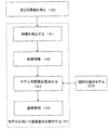
図1は、本発明の一実施形態による方法の概要を示す流れ図である。本方法は第1の画像110の入手に始まる。この第1の画像は多くの場合、MRまたはCT撮像などの高品質の撮像方法を用いて得られる。第1の画像は、母集団の一般的構造を表す解剖画像でもよい。 FIG. 1 is a flowchart illustrating an overview of a method according to an embodiment of the present invention. The method begins with obtaining the first image 110. This first image is often obtained using a high quality imaging method such as MR or CT imaging. The first image may be an anatomical image representing the general structure of the population.
図1の次の操作は、第1の画像120からの患者固有の(幾何学的)モデルの生成である。例えば、第1の画像が前立腺および隣接する臓器を描写しているとすると、このモデルがこれらの臓器の位置および境界を決める。モデルの生成は完全に自動的に行われてもよいし、あるいは、画像分割ソフトウエアを用いた臓器境界の外形描写などの専門家による手作業入力を必要としてもよい。なお、手入力はどのような外科手術の前にも実行可能であるため、この手入力は一般的には大きな時間的な問題にはならない。 The next operation in FIG. 1 is the generation of a patient-specific (geometric) model from the first image 120. For example, if the first image depicts the prostate and adjacent organs, this model determines the location and boundaries of these organs. Model generation may be done completely automatically, or it may require manual input by an expert such as delineation of an organ boundary using image segmentation software. In addition, since manual input can be performed before any surgical operation, this manual input is generally not a big time problem.
図1の3番目の操作は、第1の画像とほぼ重なり合うと見なされる第2の画像130の入手である。第2の画像は、外科手術中に超音波を用いて入手されてもよい。第2の画像と生成されたモデルとの整列の結果に基づき、操作140で、第2の画像と第1の画像との整列が行われる。 The third operation in FIG. 1 is obtaining a second image 130 that is considered to substantially overlap the first image. The second image may be obtained using ultrasound during surgery. Based on the result of the alignment between the second image and the generated model, the operation 140 aligns the second image with the first image.
本発明の一実施形態によれば、図1の処理では、2つの段階の手順で画像位置合わせが実行される。第1の段階は計画段階と考えることができ、外科手術の前に発生し、図1の操作110および120を含む。この局面では、必要であれば、専門観察者が手で画像を処理する時間が提供される。また、新しいソフトウエアツールを用いて人の介在を最小にして、診断品質の多数の画像を効率的に処理することもできる。 According to one embodiment of the present invention, in the process of FIG. 1, image registration is performed in a two-step procedure. The first phase can be thought of as a planning phase and occurs prior to surgery and includes operations 110 and 120 of FIG. In this aspect, if necessary, time is provided for the professional observer to process the image by hand. New software tools can also be used to efficiently process multiple images of diagnostic quality with minimal human intervention.
以下にさらに詳細に記載するように、この計画段階は、(i)術前MR画像から前立腺および周囲の生体構造の患者固有の有限要素網を構築する工程と、(ii)無作為に抽出した材料特性および境界条件を用いて前立腺の動き(変形を含む)の一連の有限要素解析シミュレーションを実施して、統計的動きモデル用の一組の学習データを提供する工程と、(iii)予測された有限要素網結節変位に主成分解析を適用することによって、前立腺用の統計的動きモデルを構築する工程とを含んでもよい。統計的動きモデルは、有限要素シミュレーションによって予測された変形による前立腺形状の患者固有の変動を表す統計的形状モデルの特殊な例であると考えてもよい。 As described in more detail below, this planning stage includes (i) building a patient-specific finite element network of the prostate and surrounding anatomy from preoperative MR images, and (ii) randomly extracting Performing a series of finite element analysis simulations of prostate motion (including deformation) using material properties and boundary conditions to provide a set of training data for a statistical motion model; (iii) predicted Constructing a statistical motion model for the prostate by applying principal component analysis to the finite element network nodal displacements. A statistical motion model may be considered a special example of a statistical shape model that represents patient-specific variations in prostate shape due to deformation predicted by finite element simulation.
図1の操作130および140を含む第2の段階は外科手術中に発生し、位置合わせ段階と考えることができる。なお、この局面で得られる画像は、第1の局面で得られる診断画像よりやや低画質(例えば雑音が多い)でもよい。 The second stage, including operations 130 and 140 of FIG. 1, occurs during surgery and can be considered an alignment stage. Note that the image obtained in this aspect may have a slightly lower image quality (for example, more noise) than the diagnostic image obtained in the first aspect.
以下にさらに詳細に記載するように、この位置合わせ段階は、(i)経直腸的超音波画像の特徴ベクトルを、画像強度の二次導関数を用いて計算する工程と、(ii)経直腸的超音波画像から得られた特定の位置合わせパラメータ組の尤度が最大になるまで、剛体形状パラメータおよび統計的動きモデル形状パラメータを繰り返し最適化する工程とを含んでもよい。 As described in more detail below, this registration step comprises (i) calculating a feature vector of the transrectal ultrasound image using a second derivative of the image intensity; and (ii) transrectal. Repetitively optimizing rigid body shape parameters and statistical motion model shape parameters until the likelihood of a particular set of alignment parameters obtained from a local ultrasound image is maximized.
図2の流れ図では、本発明の具体的な一実施形態が説明されており、ここでは図1の操作110が前立腺および周囲の臓器のMR画像を得る工程を含む。図2の残りの部分には、本発明の一実施形態に従って、この得られたMR画像から統計的動きモデルを生成することが示されている(図1の操作120に対応する)。なお、統計的動きモデルは外科手術の前に生成され、したがって術中のような厳しい時間的制限を受けない。 The flow diagram of FIG. 2 illustrates one specific embodiment of the present invention, where operation 110 of FIG. 1 includes obtaining MR images of the prostate and surrounding organs. The remaining portion of FIG. 2 shows that a statistical motion model is generated from this obtained MR image (corresponding to operation 120 of FIG. 1) in accordance with one embodiment of the present invention. It should be noted that the statistical motion model is generated prior to surgery and is therefore not subject to the strict time limitations as during the operation.
操作221では、診断MR画像が、(解剖学的に中央および周辺領域に分けられた)前立腺、骨盤骨、直腸、直腸、および前立腺の基部にある膀胱の形状を規定する領域に手作業で分割される。まず、球面調和関数表示を用いて前立腺を表し、次にこれを三角表面網に変換することができる。骨盤下部も網状にすることができる。 In operation 221, the diagnostic MR image is manually divided into regions that define the shape of the bladder at the base of the prostate, pelvis, rectum, rectum, and prostate (anatomically divided into central and peripheral regions). Is done. First, the spherical harmonic function representation can be used to represent the prostate, which can then be converted to a triangular surface network. The lower pelvis can also be reticulated.
操作222では、市販の有限要素解析ソフトウエアパッケージANSYS(ANSYS、Inc.、Canonsburg、米国ペンシルベニア州)に表面を取り込むことによって、基準となる有限要素網を生成する。これによって、50〜60、000個の四面体要素をもつ有限要素モデルを、ソフトウエアが提供する立体モデル化ツールを用いて構築することができる。10結節の四面体要素が未構造化網を用いる非線形形状に対応することから、これを使用することができる。この網は直腸の領域の周りで細分化することができ、これによって、網を再構築することなく、経直腸的超音波プローブをシミュレーション中に直接モデル化できる。全ての関心のある領域内の要素には標識が付けられ、生理学的範囲から無作為に抽出された材料特性がそれぞれに割り付けられる。 In operation 222, a reference finite element network is generated by capturing a surface in a commercially available finite element analysis software package ANSYS (ANSY, Inc., Canonsburg, Pa.). As a result, a finite element model having 50 to 60,000 tetrahedral elements can be constructed using a solid modeling tool provided by software. This can be used since the ten-node tetrahedral element corresponds to a non-linear shape using an unstructured network. This mesh can be subdivided around the rectal region, which allows the transrectal ultrasound probe to be modeled directly during simulation without having to reconstruct the mesh. All elements in the region of interest are labeled and each is assigned a material property randomly extracted from the physiological range.
上記処理手順では、MR画像内で観察されたままの前立腺の有限要素モデルが作り出される。次にこの観察モデル上で、有限要素解析を用いて一組のシミュレーションを行い、割り当てられた種々の境界条件および種々の材料特性の下で、前立腺がどのように変形するかを把握する。具体的には、経直腸的超音波プローブの直腸内挿入が、直腸壁を介して伝わる作用力によって、前立腺を変形させることになる。 The above procedure creates a finite element model of the prostate as observed in the MR image. Next, on this observation model, a set of simulations is performed using finite element analysis to understand how the prostate deforms under various assigned boundary conditions and various material properties. Specifically, the intrarectal insertion of a transrectal ultrasound probe will deform the prostate due to the acting force transmitted through the rectal wall.
一実施形態では、各有限要素解析シミュレーション用の材料特性22および境界条件23は次の様に決定される。全てのシミュレーションに対し、骨盤表面の変位をゼロに設定する。各シミュレーションに対して、経直腸的超音波プローブの姿勢に関する無作為な形状および水を充填した鞘の直径を設定する(非特許文献9(Hu等、2008年))。これらが境界条件23である。 In one embodiment, the material properties 22 and boundary conditions 23 for each finite element analysis simulation are determined as follows. Set the pelvic surface displacement to zero for all simulations. For each simulation, a random shape regarding the posture of the transrectal ultrasound probe and the diameter of the sheath filled with water are set (Non-Patent Document 9 (Hu et al., 2008)). These are boundary conditions 23.
全ての組織が等方性線形弾性材料の挙動を示すと仮定して、材料特性を決定する。この非圧縮性の仮定(ポアソン比ν=0.5)は、血液および他の体液の損益および潰れやすい尿道の存在によっては前立腺などの臓器に適さない場合があるため、有限要素モデル内の異なる材料に割り当てるヤング率およびポアソン比は未知であると仮定し、各シミュレーション内の各変数の既知の生理学的範囲を表す範囲から無作為抽出された割り当て値とする。 Assuming that all tissues exhibit the behavior of an isotropic linear elastic material, the material properties are determined. This incompressible assumption (Poisson's ratio ν = 0.5) differs in finite element models because it may not be suitable for organs such as the prostate depending on the profit and loss of blood and other body fluids and the presence of fragile urethra The Young's modulus and Poisson's ratio assigned to the material are assumed to be unknown, and are assigned values randomly extracted from a range representing the known physiological range of each variable in each simulation.
抽出した材料特性および境界条件を500回のシミュレーションのそれぞれに割り当てた後、結節の変位を操作223で計算する。この計算には、事前に条件設定した共役勾配反復方程式解法を用い、これをANSYS内で実行して一組の変形有限要素網224を作る。次に操作225では、種々の変形前立腺モデルの網結節点の間に固有の対応関係があることから、主成分解析を網結節の3D変位に直接適用することができる。具体的には、M個(=500)の模擬の前立腺変形のそれぞれに対し、前立腺網内のN個の結節のそれぞれの変位を計算し、結合して3N×1個のベクトルdを形成することができる。このベクトルが材料特性および境界条件の所与の組に対する前立腺の予測動きを表す。次に、主成分解析を用いてd内の変動の主モードを計算することができる。m0が未変形前立腺を表しMR画像から決まる元の有限要素モデルの結節点の3D座標を含むベクトルである場合は、変形前立腺はベクトルmによって定義され、次式で与えられる。

図3には、図2の処理の結果生じた形状変動の第1の3つのモードに対応した前立腺モデルの形状変化の実施例が説明されている。具体的には、図3は統計的動きモデルの第1の3つのモード(PC1、PC2、およびPC3)を表しており、モデルパラメータ(シグマは各モードに対応するパラメータの標準偏差)に対する前立腺の形状変化を示す。三角形網表面の結節点における表面法線ベクトルが矢印で示されている。 FIG. 3 illustrates an example of a prostate model shape change corresponding to the first three modes of shape variation resulting from the process of FIG. Specifically, FIG. 3 represents the first three modes of the statistical motion model (PC1, PC2, and PC3), where the prostate for model parameters (sigma is the standard deviation of the parameter corresponding to each mode). Shows shape change. The surface normal vectors at the nodes of the triangular mesh surface are indicated by arrows.
実際の場面では、主成分解析は、前立腺モデルの形状を説明するためのパラメータの数を減らす。これらのパラメータが(一般に複雑な方法で)入力境界条件および材料特性を表す。このようにパラメータの数を減らすと、下の説明のようにその後の画像位置合わせ手法のさらなる効率化を促進する。というのは、位置合わせ中の数値最適化によってこれらのパラメータだけを評価すればよいためである。 In actual situations, principal component analysis reduces the number of parameters to describe the shape of the prostate model. These parameters represent input boundary conditions and material properties (typically in a complex manner). Reducing the number of parameters in this way promotes further efficiency of subsequent image registration techniques as described below. This is because only these parameters need to be evaluated by numerical optimization during alignment.
図4は、本発明の一実施形態による多様画像整列を実施するための統計的動きモデルの使用を説明する流れ図である。本手法はモデル対画像位置合わせを含み、これは非特許文献19(Staib及びDuncan、1992年)の中で検討された境界発見問題と同じである。したがって、同論文に記載の手法と同様の手法を適用して、本明細書に記載の方法用の堅牢なモデル対画像位置合わせを提供する。なお、外科手術中の画像による誘導という目的のために前立腺の画像を位置合わせする実施例では、モデル対画像位置合わせは一般には(経直腸的超音波画像を得た後の)術中局面で実施されるため、一般的にはリアルタイムでほとんど人の介在なしに実施されなければならない。 FIG. 4 is a flow diagram illustrating the use of a statistical motion model to perform multi-image alignment according to one embodiment of the present invention. This approach involves model-to-image registration, which is the same as the boundary discovery problem discussed in Non-Patent Document 19 (Staib and Duncan, 1992). Accordingly, an approach similar to that described in the article is applied to provide robust model-to-image registration for the method described herein. Note that in examples where the prostate image is registered for the purpose of image-based guidance during surgery, model-to-image registration is generally performed during the intraoperative phase (after obtaining a transrectal ultrasound image). In general, it must be performed in real time with little human intervention.
前立腺のMRおよび経直腸的超音波画像における際立った特徴の一つは皮膜表面である(皮膜とは前立腺を取り囲む膜をいう)。本明細書に開示した画像位置合わせ方法では、MR由来モデルおよび3D経直腸的超音波画像から単独に計算される表面のベクトル表示を用いて、これらベクトル間の類似性を最大化することによって、モデルを経直腸的超音波画像と整列させる。この変換では、変形可能モデルの表面は、一組の位置合わせパラメータ(すなわち(c1、c2、・・・cL)で定義された剛体パラメータおよび形状パラメータ)を条件として、表面法線ベクトル場u(x)によって一意的に定義される。ここに、xはモデル空間内の点の3D座標を定義する位置ベクトル、uはその特定の点における表面法線を定義する3Dベクトル関数である。定義により、uはモデル表面上にない全ての点においてゼロである。 One of the distinguishing features in prostate MR and transrectal ultrasound images is the coating surface (the coating refers to the membrane surrounding the prostate). The image registration method disclosed herein maximizes the similarity between these vectors using a vector representation of the surface calculated solely from the MR-derived model and the 3D transrectal ultrasound image, The model is aligned with the transrectal ultrasound image. In this transformation, the surface of the deformable model is subject to a surface normal vector subject to a set of alignment parameters (ie, rigid body parameters and shape parameters defined by (c 1 , c 2 ,... C L )). It is uniquely defined by the field u (x). Here, x is a position vector that defines the 3D coordinates of a point in the model space, and u is a 3D vector function that defines the surface normal at that particular point. By definition, u is zero at every point not on the model surface.
vで示される表面法線ベクトル場を画像ごとに、二次ガウス導関数に基づく多重尺度フィルタリング技法を用いて評価することができる。このような手法では、ガウス核の幅に直接関連する特定の尺度ごとに、各ボクセルにおけるヘッシアンを計算する。次に、ヘッシアンの固有値の相対的な大きさを用いて局所画像構造を分類し、斑点状構造、管状構造、または薄板状構造を強調する(非特許文献8(Frangi等、1998年))。 The surface normal vector field denoted v can be evaluated for each image using a multi-scale filtering technique based on second order Gaussian derivatives. In such an approach, the Hessian at each voxel is calculated for each specific measure that is directly related to the width of the Gaussian kernel. Next, the local image structure is classified by using the relative size of the Hessian eigenvalue, and a spot-like structure, a tubular structure, or a thin plate-like structure is emphasized (Non-Patent Document 8 (Frangi et al., 1998)).
本発明の一実施形態では、非特許文献6(Descoteaux等、2006年)に提案されている薄板状強調フィルタの拡張が導き出されている。これは、境界表面と超音波送信方向と間の角度が変化しやすいことによる境界上の不均一な超音波画像強度特性を考慮するためである。この影響が、例えば前立腺の側面(超音波ビームの方向に平行)上の境界における強度が前立腺の下側および上側(超音波送信方向に直角)における強度に比べて小さいといったアーチファクトの原因である。 In one embodiment of the present invention, an extension of the thin plate enhancement filter proposed in Non-Patent Document 6 (Descoteaux et al., 2006) is derived. This is to take into account non-uniform ultrasonic image intensity characteristics on the boundary due to the fact that the angle between the boundary surface and the ultrasonic transmission direction is likely to change. This effect is responsible for artifacts such as, for example, that the intensity at the border on the side of the prostate (parallel to the direction of the ultrasound beam) is small compared to the intensity at the lower and upper sides of the prostate (perpendicular to the ultrasound transmission direction).
非特許文献7(Figueiredo及びGomes、2006年)に記載の元の変換では、この種類のフィルタの応答は次式で与えられる。
![]()
![]()
本明細書に記載の手法を用いて集められた経直腸的超音波データでは、このフィルタの応答はスカラ重みパラメータα、β、およびγに鈍感であることがわかった。したがってこれらを、非特許文献6(Descoteaux等、2007年)の推奨に従って一定値に設定した。ヘッシアンの計算に用いられるガウス核の幅σは全ての方向に1mmとした。 In transrectal ultrasound data collected using the techniques described herein, the filter response was found to be insensitive to scalar weighting parameters α, β, and γ. Therefore, these were set to constant values according to the recommendations of Non-Patent Document 6 (Descoteaux et al., 2007). The width σ of the Gaussian nucleus used for Hessian calculation was 1 mm in all directions.
超音波送信方向を3Dベクトルbで定義すれば、改良したフィルタ応答は次式で与えられる。
![]()
表面法線ベクトル場は次式で与えられる。
![]()
The surface normal vector field is given by
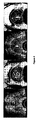
図5は、上記方法を用いて3D経直腸的超音波画像から推定した表面法線ベクトル場の実施例を表している。具体的には、図5は前立腺の以下の4つの画像を示す。左から右へ、
a)1番目の画像は元の経直腸的超音波体積を通る横断面を表す。
b)2番目の画像はフィルタ式(3)で先に定義されたフィルタの応答を表す。
c)3番目の画像は式(4)で与えられる抽出された(断面上に投影された)ベクトル場vを表す。
d)4番目の画像は前立腺表面部の周りの(3番目の画像に示した)関心のある領域の拡大視野を提供している。
FIG. 5 shows an example of a surface normal vector field estimated from 3D transrectal ultrasound images using the method described above. Specifically, FIG. 5 shows the following four images of the prostate. From left to right,
a) The first image represents a cross section through the original transrectal ultrasound volume.
b) The second image represents the response of the filter previously defined by filter equation (3).
c) The third image represents the extracted vector field v (projected on the cross section) given by equation (4).
d) The fourth image provides an enlarged field of view of the area of interest (shown in the third image) around the prostate surface.
ここで図4に戻ると、第2の(超音波)画像が操作130で一旦得られたら、操作141でこの画像から関連する特徴が抽出される。非特許文献19(Staib及びDuncan、1992年)の手法では、画像から抽出された上記表面法線ベクトル場などの特徴は、変形可能モデルから決定された表面法線ベクトル場の雑音破損版であると考えてもよい。この変換では、画像空間Ωimage内の指標iによって参照される特定の画像ボクセルが、座標yi=(xi、yi、zi)および推定表面法線ベクトルviを有する確率を、下式の確率混合モデルとして表すことができる。
![]()
![]()
![]()
![]()
式(6)では、2つのパラメータをもつ特殊分類の等方性ガウス分布が用いられ、共分散行列Σjが、スペクトル分解と同様の方法で一組の直交ベクトルwdの展開として表される。故に、
![]()
![]()
式(7)では、kはスカラ濃度パラメータであり、雑音レベルに応じて変化する。一実施形態では、kを小さな値0.1<k<0.5に設定して強い局所的一致の寄与を弱めた。確率密度関数の要求事項を満たすために、正規化常数C(k)を再帰積分によって推定した。角度θは、点jで計算されたモデル表面法線ベクトルとボクセルiで計算された画像表面法線ベクトルとの間の角度である。 In Equation (7), k is a scalar density parameter, which varies according to the noise level. In one embodiment, k was set to a small value 0.1 <k <0.5 to weaken the contribution of strong local matches. In order to satisfy the requirements of the probability density function, the normalized constant C (k) was estimated by recursive integration. The angle θ is the angle between the model surface normal vector calculated at point j and the image surface normal vector calculated at voxel i.
一組の画像特徴142を第2の画像から(および、例えば図5の3番目の図に示したように)一旦抽出したら、操作143でモデル対画像位置合わせが実施される。位置合わせ手法は、(例えば)図2の方法を用いて生成した統計的動きモデル226を用いる。先に述べたとおり、統計的動きモデルは通常は術前局面で生成される。 Once a set of image features 142 has been extracted from the second image (and, for example, as shown in the third diagram of FIG. 5), model-to-image registration is performed at operation 143. The alignment technique uses (for example) a statistical motion model 226 generated using the method of FIG. As mentioned earlier, statistical motion models are usually generated during the preoperative phase.
操作143の位置合わせ手法は、雑音の同時確率を最大にする最適変換パラメータを見付けることを目的とする。異なるボクセルにおける雑音値は独立していると仮定して(非特許文献19(Staib及びDuncan、1992年))、我々は次の対数尤度目的関数に辿り着いた。
期待値最大化(EM)アルゴリズムが、式(9)の尤度関数を最大化する効率的方法を提供する(非特許文献7(Figueiredo及びGomes、2006年))。Matelab(The Mathworks、Inc.、Natik、米国マッチューセッツ州)を用いてEMアルゴリズムを実行し、位置合わせパラメータを繰り返し最適化して式(9)を最大化した。 The Expectation Maximization (EM) algorithm provides an efficient way to maximize the likelihood function of Equation (9) (Non-Patent Document 7 (Figueiredo and Gomes, 2006)). The EM algorithm was performed using Matlab (The Mathworks, Inc., Natik, Massachusetts, USA) and the alignment parameters were iteratively optimized to maximize equation (9).
実際には、位置合わせ手法では、統計的動きモデルのパラメータ組によって定義される多次元空間内を検索して、(MR画像から得られた)変形された幾何学的モデルの形状が経直腸的超音波画像内に表示された前立腺の表面に最適一致するパラメータを見付ける。統計的動きモデルパラメータ値の各組は有限要素モデルの新しい位置および形状に対応する。主成分解析を使用すると、モデルの変形候補を系統的かつ効率的な方法で検討できる。位置合わせ手法の出力は、モデル表面が、経直腸的超音波画像内で観察した前立腺表面に最も忠実に一致するようにモデルを変形させるパラメータ値の組である。 In practice, the registration technique searches the multidimensional space defined by the statistical motion model parameter set and the shape of the deformed geometric model (obtained from the MR images) is transrectally converted. Find the parameters that best match the surface of the prostate displayed in the ultrasound image. Each set of statistical motion model parameter values corresponds to a new position and shape of the finite element model. Using principal component analysis, model deformation candidates can be studied in a systematic and efficient manner. The output of the registration technique is a set of parameter values that deforms the model so that the model surface most closely matches the prostate surface observed in the transrectal ultrasound image.
最適一致変形が一旦決まったら、変位の組を作って高密度変位場を形成する。これらの変位は、MR画像から得られた元のモデルから、経直腸的超音波画像に最適一致すると見られる変形モデルに書き換えられる。次に、これらの同じ変位を元のMR画像のボクセルに適用して、MR画像を経直腸的超音波画像に揃えることができる。(反対に、逆向きの変位を経直腸的超音波画像に適用して、それをMR画像と揃えることもできる)。 Once the optimal matching deformation is determined, a set of displacements is created to form a high-density displacement field. These displacements are rewritten from the original model obtained from the MR image to a deformation model that appears to best match the transrectal ultrasound image. These same displacements can then be applied to the original MR image voxels to align the MR image with the transrectal ultrasound image. (Conversely, a reverse displacement can be applied to the transrectal ultrasound image to align it with the MR image).
上記の手法を前立腺癌患者7人のデータを用いて検討した(全ての患者から文書による参加の同意が得られた)。全身麻酔状態での型誘導による経会陰針生検の前に、前立腺のT2重み付けMR画像体積を求めた。針挿入の直前に、B−Kプロップフォーカススキャナ(B-K ProFocus scanner、英国B-K Medical Ltd., www.bkmed.com参照)を用いて前立腺の3D経直腸的超音波画像を入手した。機械式歩進装置(Tyman Medical Inc.,米国ミズーリ州)を用いて超音波プローブ(B−K8658T、5〜7.5MHz発振器)を直腸の軸に沿って平行移動して、一組の平行横断Bモード画像を撮影し、2mm間隔でスキャナに保存した。 The above approach was examined using data from 7 prostate cancer patients (all patients gave written consent to participate). Prior to transperineal needle biopsy with mold induction in general anesthesia, a T2-weighted MR image volume of the prostate was determined. Immediately prior to needle insertion, 3D transrectal ultrasound images of the prostate were obtained using a BK ProFocus scanner (see B-K ProFocus scanner, UK B-K Medical Ltd., www.bkmed.com). A set of parallel traverses using a mechanical stepping device (Tyman Medical Inc., Missouri, USA) translating an ultrasound probe (B-K8658T, 5-7.5 MHz oscillator) along the rectal axis. B-mode images were taken and stored in the scanner at 2 mm intervals.
まず各超音波画像を、寸法1mmの等方性ボクセルの体積内へ再抽出した。各ボクセルにおいて、高速フーリエ変換に基づく実装を用いて、周波数領域内でヘッシアンを計算した。迅速かつ単純な手順を用いて、経直腸的超音波体積に対する統計的動きモデルの姿勢を初期化し、前立腺の頂点および基部の2点を手作業で識別した。一旦位置合わせし、統計的動きモデルの最終事例を四面体要素用の形状関数を用いて立体有限要素網で補間することによって、高密度変位場を関心のある体積全体にわたって計算した。 First, each ultrasonic image was re-extracted into the volume of an isotropic voxel having a size of 1 mm. In each voxel, the Hessian was calculated in the frequency domain using an implementation based on Fast Fourier Transform. A quick and simple procedure was used to initialize the pose of the statistical motion model relative to the transrectal ultrasound volume and manually identify the two points at the prostate apex and base. Once aligned, the dense motion field was calculated over the volume of interest by interpolating the final case of the statistical motion model with a solid finite element network using shape functions for tetrahedral elements.
上記手順から得られる画像位置合わせの精度を検討した。検討は、嚢胞、石灰化、尿道、恥骨前立腺靱帯、および精嚢と精管と前立腺の正中線との間の接合部など解剖学的目標に対応するMR体積および経直腸的超音波体積の両方で、手作業で確認することによって行った。次に、MR画像内に定義された目標の3D座標を、高密度変位場を用いて経直腸的超音波座標内へ展開した。識別した目標と展開された目標との各対について、標的位置合わせ誤差を計算した。この誤差は、手作業で定義した目標点と経直腸的超音波画像の座標系内に展開された目標点との間の距離として定義される。高密度変位場を用いてMR画像も歪曲させることによって、位置合わせの視覚的評価が可能になった。なお、この方法では前立腺の表面のみを位置合わせするものの、変形可能な有限要素モデルを使用することによって、内部構造の変位を瞬時に計算できる。 The accuracy of image alignment obtained from the above procedure was examined. Consider both MR and transrectal ultrasound volumes corresponding to anatomical goals such as cysts, calcifications, urethra, pubic prostate ligaments, and junctions between seminal vesicles and vas deferens and prostate midline So, it was done by checking manually. Next, the target 3D coordinates defined in the MR image were developed into transrectal ultrasound coordinates using a high density displacement field. Target registration errors were calculated for each pair of identified and deployed targets. This error is defined as the distance between the manually defined target point and the target point developed in the coordinate system of the transrectal ultrasound image. By distorting the MR image using a high-density displacement field, it has become possible to visually evaluate the alignment. Although this method aligns only the surface of the prostate, the displacement of the internal structure can be calculated instantaneously by using a deformable finite element model.
前立腺内の目標に対して計算された目標基準標的位置合わせ誤差を下の表1に示す。全7事例(26目標)の二乗平均平方根(RMS)標的位置合わせ誤差は2.66mmであった。この数値は画像対画像位置合わせ全体の精度を代表すると考えられる。
図6では、本発明の一実施形態による位置合わせ実施例から計算された高密度変位場を用いて歪曲させたMRおよび対象の経直腸的超音波画像の結果が説明されている。具体的には、図6は事例1の経直腸的超音波体積の横断面画像(1番目および3番目の画像)であり、変形可能な位置合わせ後の対応する歪曲MR画像(2番目および4番目の画像)が一緒に示されている。矢印は、きちんと並べられた目標を示している。 FIG. 6 illustrates the results of MR and subject transrectal ultrasound images distorted using a high-density displacement field calculated from an alignment example according to one embodiment of the present invention. Specifically, FIG. 6 is a cross-sectional image (first and third images) of the transrectal ultrasound volume of Case 1 and the corresponding distorted MR images (second and fourth) after deformable alignment. The second image) is shown together. The arrows indicate the goals that are neatly arranged.
したがって上記の手法では、同じ対象の2つの画像が入力として提供されている。これらの画像の1つは、関心のある対象の幾何学的モデルを作るために分割される。例えば臓器の幾何学的モデルは、表面網の態様でもよい。次に幾何学的モデルおよび残りの画像の両方に対して、3Dベクトル場が計算される。表面網の場合は、ベクトル場はその表面全体の局所表面法線ベクトルの組である。管状構造(血管など)の場合は、ベクトル場は構造に沿った局所方向を表すベクトルの組である。画像に、例えば面状または管状構造を適切に検出するよう調整された二次ガウス画像フィルタを用いて、対応するベクトル場が画像から直接計算される。次に、ベクトル場を整列させることによって、ベクトル類似性の数値が最小になるようにモデルを画像に位置合わせする。位置合わせ手法の間に、(例えば統計的形状モデルによって表された)臓器の動きモデルによって定義される制約に従って、幾何学的モデルから得られたベクトル場を変形させる。幾何学的モデルとそれが得られた元の入力画像との間の空間的変換が分かるため、この位置合わせの出力を用いて、入力画像間の位置合わせ変換を計算することができる。 Therefore, in the above method, two images of the same object are provided as input. One of these images is segmented to create a geometric model of the object of interest. For example, the geometric model of the organ may be in the form of a surface network. A 3D vector field is then calculated for both the geometric model and the remaining image. In the case of a surface network, the vector field is a set of local surface normal vectors for the entire surface. In the case of a tubular structure (such as a blood vessel), the vector field is a set of vectors representing the local direction along the structure. The corresponding vector field is calculated directly from the image using a second order Gaussian image filter, adjusted to properly detect, for example, planar or tubular structures in the image. The model is then aligned with the image so that the vector similarity values are minimized by aligning the vector field. During the registration procedure, the vector field obtained from the geometric model is deformed according to the constraints defined by the organ motion model (eg represented by a statistical shape model). Since the spatial transformation between the geometric model and the original input image from which it was obtained is known, this registration output can be used to calculate a registration transformation between the input images.
上記手法を用いることによって、超音波画像などの従来「困難」であった画像が含まれているときも、自動または半自動の多様画像位置合わせが可能になる。このような方法を用いて、(例えば)針生検、および高周波治療、小線源治療、冷凍治療、光力学治療、高密度焦点式超音波、および高周波焼灼などの低浸襲介入の途中に、前立腺の術前MRを術中経直腸的超音波画像に位置合わせすることができる。一実施形態では、(術前)MR画像から得られた患者固有の有限要素モデルの動きの生体工学的シミュレーションによってもたらされる学習データを用いて、まず前立腺の統計的動きモデルが構築される。次に、前立腺の表面の推定法線ベクトルを表すボクセル強度基準の特徴を条件として、統計的動きモデル事例の形状の尤度を最大化することによって、統計的動きモデルが3D経直腸的超音波画像に位置合わせされる。7人の患者から得たデータを用い、T2MRを3D経直腸的超音波画像に位置合わせする精度を、前立腺内の解剖学的目標を用いて評価してきた。この評価の結果、二乗平均平方根標的位置合わせ誤差は2.66mmであった。すなわち前立腺のMRおよび超音波画像の位置合わせの用途に対し、使用者の関わりは最小で、本明細書に記載の手法が正確かつ変形可能な位置合わせを提供することが実証された。 By using the above method, automatic or semi-automatic multi-image alignment can be performed even when images that have been conventionally “difficult” such as ultrasonic images are included. Using such methods, during (for example) needle biopsy and low invasive interventions such as radiofrequency therapy, brachytherapy, cryotherapy, photodynamic therapy, high intensity focused ultrasound, and radiofrequency ablation, The preoperative MR of the prostate can be registered with intraoperative transrectal ultrasound images. In one embodiment, a statistical motion model of the prostate is first constructed using learning data provided by biomechanical simulation of patient-specific finite element model motion obtained from (pre-operative) MR images. The statistical motion model is then transformed into 3D transrectal ultrasound by maximizing the likelihood of the shape of the statistical motion model case, subject to the characteristics of the voxel intensity criterion representing the estimated normal vector of the prostate surface. Aligned to the image. Using data from 7 patients, the accuracy of aligning T2MR with 3D transrectal ultrasound images has been evaluated using anatomical targets within the prostate. As a result of this evaluation, the root mean square target alignment error was 2.66 mm. That is, for MR MR and ultrasound image registration applications of the prostate, it has been demonstrated that the user's involvement is minimal and the techniques described herein provide accurate and deformable registration.
モデル対画像位置合わせ方法は、MR画像から構築された統計的生体工学的結合モデルを用いる。モデルの生成にはMR画像の手作業による分割が含まれ、コンピュータ計算が中心となる(処理時間は、現在の計算設備で一般に30〜40時間)。しかしモデル生成は、MR画像入手と外科的誘導に画像位置合わせが必要な手術との間に実施されるため、臨床的流れに大きく影響することはない。これに対し、モデル対画像位置合わせ(生成済モデルを使用する)は現在、2.33GHzインテルコア(Intel(R) CoreTM)デュアルCPU演算素子および3GBのRAMを備えた卓上型PCを用いて、2分で実行可能である。本明細書に記載の本手法は十分に高い精度があり、MR標的前立腺生検および介入に臨床的に有用である。 The model-to-image registration method uses a statistical biomechanical joint model constructed from MR images. Model generation involves manual segmentation of MR images and is centered on computer calculations (processing time is typically 30-40 hours with current computing facilities). However, model generation does not significantly affect clinical flow because it is performed between MR image acquisition and surgery that requires image alignment for surgical guidance. In contrast, model-to-image registration (using the generated model) is currently using a desktop PC with a 2.33 GHz Intel (R) Core ( TM ) dual CPU computing element and 3 GB RAM. It can be done in 2 minutes. The technique described herein is sufficiently accurate and is clinically useful for MR target prostate biopsy and intervention.
上記説明は、高解像MR画像から得られる前立腺の変形可能な3Dモデルを、画像誘導による針生検および治療の途用の3D経直腸的超音波画像に自動的に位置合わせすることに注目してきたものの、本明細書に記載の手法は他の画像位置合わせ問題にも直接適用できる。本手法は、具体的には次の基準が適用される状況に関連する。すなわち、(a)ある画像がもう一つ画像と大きく異なるために強度基準位置合わせアルゴリズムをうまく適用できない、(b)ある画像から顕著な特徴を自動的に抽出することが難しくて、位置合わせが用いられる用途が強いる時間的制約を考慮すると、特徴基準位置合わせアルゴリズムは現実的ではない、および(c)何かによって表された物理的特徴に基づく臓器の幾何学的モデルが存在する、または応用例全体の作業の流れに大きな影響を与えることなく、全自動または半自動分割ソフトウエアを用いて得ることができる、状況である。画像誘導による手術の分野における多くの応用例がこの基準に合致する。 The above description has focused on automatically aligning a deformable 3D model of the prostate derived from high-resolution MR images with 3D transrectal ultrasound images for image-guided needle biopsy and treatment. However, the techniques described herein can be directly applied to other image registration problems. This approach is specifically related to situations where the following criteria apply: That is, (a) the intensity reference registration algorithm cannot be applied well because one image is significantly different from the other image, (b) it is difficult to automatically extract significant features from one image, Given the time constraints imposed by the application used, the feature-based registration algorithm is not realistic, and (c) there is a geometric model of the organ based on the physical features represented by something, or the application A situation that can be obtained using fully automatic or semi-automatic segmentation software without significantly affecting the overall workflow. Many applications in the field of image guided surgery meet this criterion.
要約すれば、上記実施形態を実施例だけで説明してきたが、当業者は、添付された特許請求の範囲によって定義される本発明の範囲にある多数の改変形態候補または変形形態候補を想起することができる。 In summary, the above embodiments have been described by way of example only, but those skilled in the art will recognize a number of candidate variations or variations within the scope of the present invention as defined by the appended claims. be able to.
Claims (30)
個々の被検者の生体臓器の患者固有の表示または母集団の生体臓器の表示を含む第1の医用画像を得る工程と、
前記第1の医用画像内の前記臓器の表面を識別する工程と、
前記表面を用いて、患者用の前記臓器の三次元形状または母集団用の前記臓器の代表的形状を表す幾何学的モデルを得る工程と、
前記幾何学的モデルを用いて、前記臓器の物理的な動きおよび変形を予測するために使用することができる動きモデルを得る工程と、
前記患者または別の患者の前記臓器の表示を含む第2の医用画像を得る工程と、
第1のベクトル場を表す前記幾何学的モデルの表面法線ベクトルと、第2のベクトル場を表す前記第2の医用画像をフィルタにかけることによって得られた臓器表面の推定表面法線ベクトルとの間の整列を決定する工程であって、数学的変換を前記幾何学的モデルに適用して、第1のベクトル場と第2のベクトル場との間の方向整列の度合いを最大にする工程を含み、前記幾何学的モデルおよび前記第1のベクトル場の空間的位置、方向、および形状を、前記動きモデルに従って変えて前記整列を実現する工程と、
前記決定された整列を基にして、第1および第2の医用画像を互いに位置合わせする工程とを備える、方法。 A method of aligning two medical images,
Obtaining a first medical image comprising a patient-specific display of a living organ of an individual subject or a display of a living organ of a population;
Identifying the surface of the organ in the first medical image;
Using the surface to obtain a geometric model representing a three-dimensional shape of the organ for a patient or a representative shape of the organ for a population;
Using the geometric model to obtain a motion model that can be used to predict physical motion and deformation of the organ;
Obtaining a second medical image including a representation of the organ of the patient or another patient;
A surface normal vector of the geometric model representing a first vector field, and an estimated surface normal vector of an organ surface obtained by filtering the second medical image representing a second vector field; Determining an alignment between and applying a mathematical transformation to the geometric model to maximize the degree of directional alignment between the first vector field and the second vector field. Changing the spatial position, direction, and shape of the geometric model and the first vector field according to the motion model to achieve the alignment;
Aligning the first and second medical images with each other based on the determined alignment.
第1の医用画像内の臓器表面を識別する手段と、
識別された表面を用いて3D幾何学的モデルを構築し、前記3D幾何学的モデルを用いて、前記臓器の物理的動きおよび変形を予測するために用いることができる動きモデルを得る手段と、
前記医用画像をフィルタにかけることによって、前記幾何学的モデルから第1の表面法線ベクトル場を得、第2の医用画像から第2の表面法線ベクトル場を得る手段と、
前記第1のベクトル場と前記第2のベクトル場との間の整列を決定する手段であって、前記整列の決定は、数学的変換を前記幾何学的モデルに適用して第1のベクトル場と第2のベクトル場との間の方向整列の程度を最大にすることを含み、前記幾何学的モデルおよび前記第1のベクトル場の空間的位置、方向、および形状が前記動きモデルに従って変えられて前記整列を実現し、それによって前記幾何学的モデルの変形を、前記動きモデルによって定義された制約に従って調整する手段と、
前記決定された整列に基づいて、前記第1および第2の医用画像を互いに位置合わせする手段と、を備える装置。 An apparatus for aligning two medical images,
Means for identifying an organ surface in the first medical image;
Means for building a 3D geometric model using the identified surface, and using the 3D geometric model to obtain a motion model that can be used to predict physical motion and deformation of the organ;
Means for obtaining a first surface normal vector field from the geometric model and obtaining a second surface normal vector field from the second medical image by filtering the medical image;
Means for determining an alignment between the first vector field and the second vector field, the alignment determination applying a mathematical transformation to the geometric model; Maximizing the degree of directional alignment between the first and second vector fields, the spatial position, direction and shape of the geometric model and the first vector field being varied according to the motion model Means for achieving the alignment, thereby adjusting the deformation of the geometric model according to the constraints defined by the motion model;
Means for aligning the first and second medical images with each other based on the determined alignment.
臓器の表面を含む第1の医用画像内の前記臓器の表面を識別する画像処理システムと、
前記識別された表面を用いて前記臓器表面の3D幾何学的モデルを構築するモデル化システムと、
前記3D幾何学的モデルから前記臓器の動きモデルを構築するモデル化システムと、
前記幾何学的モデルおよび前記第2の医用画像から、それぞれ第1および第2の表面法線ベクトル場を計算する画像処理システムと、
前記第1のベクトル場と前記第2のベクトル場との間の整列を決定する数値最適化システムであって、前記整列の決定は、数学的変換を前記幾何学的モデルに適用して前記第1のベクトル場と前記第2のベクトル場との間の方向整列の程度を最大にすることを含み、前記幾何学的モデルおよび前記第1のベクトル場の空間的位置、方向、および形状が前記動きモデルに従って変更されて前記整列を実現し、それによって前記幾何学的モデルの変形を、前記動きモデルに従って調整する数値最適化システムと、
前記決定された整列に基づいて、前記第1および第2の医用画像を互いに位置合わせする画像位置合わせシステムと、を備える装置。 An apparatus for aligning two medical images,
An image processing system for identifying a surface of the organ in a first medical image including the surface of the organ;
A modeling system that uses the identified surface to construct a 3D geometric model of the organ surface;
A modeling system for constructing a motion model of the organ from the 3D geometric model;
An image processing system for calculating first and second surface normal vector fields from the geometric model and the second medical image, respectively;
A numerical optimization system for determining an alignment between the first vector field and the second vector field, wherein the alignment is determined by applying a mathematical transformation to the geometric model. Maximizing the degree of directional alignment between one vector field and the second vector field, wherein the geometric model and the spatial position, direction, and shape of the first vector field are A numerical optimization system that is modified according to a motion model to achieve the alignment, thereby adjusting the deformation of the geometric model according to the motion model;
An image alignment system for aligning the first and second medical images with each other based on the determined alignment.
Applications Claiming Priority (3)
| Application Number | Priority Date | Filing Date | Title |
|---|---|---|---|
| GBGB0913930.4A GB0913930D0 (en) | 2009-08-07 | 2009-08-07 | Apparatus and method for registering two medical images |
| GB0913930.4 | 2009-08-07 | ||
| PCT/GB2010/001480 WO2011015822A1 (en) | 2009-08-07 | 2010-08-05 | Apparatus and method for registering two medical images |
Publications (3)
| Publication Number | Publication Date |
|---|---|
| JP2013501290A JP2013501290A (en) | 2013-01-10 |
| JP2013501290A5 JP2013501290A5 (en) | 2013-07-11 |
| JP5520378B2 true JP5520378B2 (en) | 2014-06-11 |
Family
ID=41129898
Family Applications (1)
| Application Number | Title | Priority Date | Filing Date |
|---|---|---|---|
| JP2012523378A Expired - Fee Related JP5520378B2 (en) | 2009-08-07 | 2010-08-05 | Apparatus and method for aligning two medical images |
Country Status (7)
| Country | Link |
|---|---|
| US (1) | US8620055B2 (en) |
| EP (1) | EP2462560B1 (en) |
| JP (1) | JP5520378B2 (en) |
| AU (1) | AU2010280527B2 (en) |
| CA (1) | CA2769918C (en) |
| GB (1) | GB0913930D0 (en) |
| WO (1) | WO2011015822A1 (en) |
Cited By (5)
| Publication number | Priority date | Publication date | Assignee | Title |
|---|---|---|---|---|
| WO2019164272A1 (en) * | 2018-02-20 | 2019-08-29 | (주)휴톰 | Method and device for providing surgical image |
| KR102013837B1 (en) * | 2018-02-20 | 2019-10-21 | (주)휴톰 | Method and apparatus for providing surgical video |
| JP2019194906A (en) * | 2014-03-28 | 2019-11-07 | ハートフロー, インコーポレイテッド | Systems and methods for data- and model-driven image reconstruction and correction |
| US11138746B2 (en) | 2017-07-03 | 2021-10-05 | Ricoh Company, Ltd. | Diagnostic support system and diagnostic support method |
| US11854281B2 (en) | 2019-08-16 | 2023-12-26 | The Research Foundation For The State University Of New York | System, method, and computer-accessible medium for processing brain images and extracting neuronal structures |
Families Citing this family (242)
| Publication number | Priority date | Publication date | Assignee | Title |
|---|---|---|---|---|
| US9867530B2 (en) | 2006-08-14 | 2018-01-16 | Volcano Corporation | Telescopic side port catheter device with imaging system and method for accessing side branch occlusions |
| US9596993B2 (en) | 2007-07-12 | 2017-03-21 | Volcano Corporation | Automatic calibration systems and methods of use |
| WO2009009802A1 (en) | 2007-07-12 | 2009-01-15 | Volcano Corporation | Oct-ivus catheter for concurrent luminal imaging |
| WO2009009799A1 (en) | 2007-07-12 | 2009-01-15 | Volcano Corporation | Catheter for in vivo imaging |
| US8200466B2 (en) | 2008-07-21 | 2012-06-12 | The Board Of Trustees Of The Leland Stanford Junior University | Method for tuning patient-specific cardiovascular simulations |
| US9405886B2 (en) | 2009-03-17 | 2016-08-02 | The Board Of Trustees Of The Leland Stanford Junior University | Method for determining cardiovascular information |
| EP2309450B1 (en) * | 2009-09-21 | 2016-04-06 | Orcamp AB | Method for characterizing a blood vessel |
| JP5820383B2 (en) * | 2009-10-30 | 2015-11-24 | コーニンクレッカ フィリップス エヌ ヴェKoninklijke Philips N.V. | Three-dimensional analysis of lesions represented by image data |
| DE102010018261B4 (en) * | 2010-04-26 | 2012-07-12 | Siemens Aktiengesellschaft | Method and computer system for automatic vectorization of a vascular tree |
| US8315812B2 (en) | 2010-08-12 | 2012-11-20 | Heartflow, Inc. | Method and system for patient-specific modeling of blood flow |
| US10292617B2 (en) | 2010-09-30 | 2019-05-21 | Aspect Imaging Ltd. | Automated tuning and frequency matching with motor movement of RF coil in a magnetic resonance laboratory animal handling system |
| BR112013010661A2 (en) * | 2010-11-05 | 2020-10-06 | Koninklijke Philips Electronics N.V. | cache controller for use on a system, image client, image server, workstation, image formation device, storage method and computer program product. |
| US20120113146A1 (en) * | 2010-11-10 | 2012-05-10 | Patrick Michael Virtue | Methods, apparatus and articles of manufacture to combine segmentations of medical diagnostic images |
| US11141063B2 (en) | 2010-12-23 | 2021-10-12 | Philips Image Guided Therapy Corporation | Integrated system architectures and methods of use |
| US11040140B2 (en) | 2010-12-31 | 2021-06-22 | Philips Image Guided Therapy Corporation | Deep vein thrombosis therapeutic methods |
| US20130308849A1 (en) * | 2011-02-11 | 2013-11-21 | Emory University | Systems, methods and computer readable storage mediums storing instructions for 3d registration of medical images |
| WO2012112907A2 (en) * | 2011-02-17 | 2012-08-23 | Dartmouth College | System and method for providing registration between breast shapes before and during surgery |
| US8855394B2 (en) * | 2011-07-01 | 2014-10-07 | Carestream Health, Inc. | Methods and apparatus for texture based filter fusion for CBCT system and cone-beam image reconstruction |
| US9360630B2 (en) | 2011-08-31 | 2016-06-07 | Volcano Corporation | Optical-electrical rotary joint and methods of use |
| KR101828411B1 (en) * | 2011-09-21 | 2018-02-13 | 삼성전자주식회사 | Image processing method and image processing apparatus |
| US8605972B2 (en) | 2012-03-02 | 2013-12-10 | Sony Corporation | Automatic image alignment |
| US9240032B2 (en) * | 2012-03-15 | 2016-01-19 | Koninklijke Philips N.V. | Multi-modality deformable registration |
| US9105207B2 (en) | 2012-05-02 | 2015-08-11 | Empire Technology Development Llc | Four dimensional image registration using dynamical model for augmented reality in medical applications |
| JP5946127B2 (en) * | 2012-05-11 | 2016-07-05 | 富士通株式会社 | Simulation method, simulation apparatus, and simulation program |
| US11871901B2 (en) | 2012-05-20 | 2024-01-16 | Cilag Gmbh International | Method for situational awareness for surgical network or surgical network connected device capable of adjusting function based on a sensed situation or usage |
| US20140071125A1 (en) * | 2012-09-11 | 2014-03-13 | The Johns Hopkins University | Patient-Specific Segmentation, Analysis, and Modeling from 3-Dimensional Ultrasound Image Data |
| US10398386B2 (en) | 2012-09-12 | 2019-09-03 | Heartflow, Inc. | Systems and methods for estimating blood flow characteristics from vessel geometry and physiology |
| US10433740B2 (en) | 2012-09-12 | 2019-10-08 | Heartflow, Inc. | Systems and methods for estimating ischemia and blood flow characteristics from vessel geometry and physiology |
| US20140086464A1 (en) | 2012-09-21 | 2014-03-27 | Mim Software Inc. | Dynamic local registration system and method |
| US9307926B2 (en) | 2012-10-05 | 2016-04-12 | Volcano Corporation | Automatic stent detection |
| US10568586B2 (en) | 2012-10-05 | 2020-02-25 | Volcano Corporation | Systems for indicating parameters in an imaging data set and methods of use |
| US9292918B2 (en) | 2012-10-05 | 2016-03-22 | Volcano Corporation | Methods and systems for transforming luminal images |
| JP2015532536A (en) | 2012-10-05 | 2015-11-09 | デイビッド ウェルフォード, | System and method for amplifying light |
| US9367965B2 (en) | 2012-10-05 | 2016-06-14 | Volcano Corporation | Systems and methods for generating images of tissue |
| US9858668B2 (en) | 2012-10-05 | 2018-01-02 | Volcano Corporation | Guidewire artifact removal in images |
| US11272845B2 (en) | 2012-10-05 | 2022-03-15 | Philips Image Guided Therapy Corporation | System and method for instant and automatic border detection |
| US10070827B2 (en) | 2012-10-05 | 2018-09-11 | Volcano Corporation | Automatic image playback |
| US9324141B2 (en) | 2012-10-05 | 2016-04-26 | Volcano Corporation | Removal of A-scan streaking artifact |
| US9286673B2 (en) | 2012-10-05 | 2016-03-15 | Volcano Corporation | Systems for correcting distortions in a medical image and methods of use thereof |
| US9840734B2 (en) | 2012-10-22 | 2017-12-12 | Raindance Technologies, Inc. | Methods for analyzing DNA |
| EP2912629B1 (en) | 2012-10-26 | 2018-10-03 | Brainlab AG | Matching patient images and images of an anatomical atlas |
| US9761014B2 (en) * | 2012-11-15 | 2017-09-12 | Siemens Healthcare Gmbh | System and method for registering pre-operative and intra-operative images using biomechanical model simulations |
| EP2923337B1 (en) * | 2012-11-23 | 2016-03-30 | Koninklijke Philips N.V. | Generating a key-image from a medical image |
| US9370328B2 (en) * | 2012-11-29 | 2016-06-21 | University Of Washington Through Its Center For Commercialization | Methods and systems for determining tumor boundary characteristics |
| US8995719B2 (en) * | 2012-12-10 | 2015-03-31 | Intel Corporation | Techniques for improved image disparity estimation |
| EP2931132B1 (en) | 2012-12-13 | 2023-07-05 | Philips Image Guided Therapy Corporation | System for targeted cannulation |
| WO2014099899A1 (en) | 2012-12-20 | 2014-06-26 | Jeremy Stigall | Smooth transition catheters |
| EP2934310A4 (en) | 2012-12-20 | 2016-10-12 | Nathaniel J Kemp | Optical coherence tomography system that is reconfigurable between different imaging modes |
| US11406498B2 (en) | 2012-12-20 | 2022-08-09 | Philips Image Guided Therapy Corporation | Implant delivery system and implants |
| US10942022B2 (en) | 2012-12-20 | 2021-03-09 | Philips Image Guided Therapy Corporation | Manual calibration of imaging system |
| CA2895770A1 (en) | 2012-12-20 | 2014-07-24 | Jeremy Stigall | Locating intravascular images |
| US10939826B2 (en) | 2012-12-20 | 2021-03-09 | Philips Image Guided Therapy Corporation | Aspirating and removing biological material |
| EP2934280B1 (en) | 2012-12-21 | 2022-10-19 | Mai, Jerome | Ultrasound imaging with variable line density |
| US10058284B2 (en) | 2012-12-21 | 2018-08-28 | Volcano Corporation | Simultaneous imaging, monitoring, and therapy |
| WO2014100162A1 (en) | 2012-12-21 | 2014-06-26 | Kemp Nathaniel J | Power-efficient optical buffering using optical switch |
| US9486143B2 (en) | 2012-12-21 | 2016-11-08 | Volcano Corporation | Intravascular forward imaging device |
| EP2936426B1 (en) | 2012-12-21 | 2021-10-13 | Jason Spencer | System and method for graphical processing of medical data |
| WO2014100606A1 (en) | 2012-12-21 | 2014-06-26 | Meyer, Douglas | Rotational ultrasound imaging catheter with extended catheter body telescope |
| US10413317B2 (en) | 2012-12-21 | 2019-09-17 | Volcano Corporation | System and method for catheter steering and operation |
| US10327695B2 (en) | 2012-12-21 | 2019-06-25 | Volcano Corporation | Functional gain measurement technique and representation |
| CA2896006A1 (en) | 2012-12-21 | 2014-06-26 | David Welford | Systems and methods for narrowing a wavelength emission of light |
| EP2934323A4 (en) | 2012-12-21 | 2016-08-17 | Andrew Hancock | System and method for multipath processing of image signals |
| US9612105B2 (en) | 2012-12-21 | 2017-04-04 | Volcano Corporation | Polarization sensitive optical coherence tomography system |
| CN103942768B (en) | 2013-01-18 | 2017-05-24 | 诺基亚技术有限公司 | Image fusion method and apparatus |
| US9367761B2 (en) * | 2013-02-15 | 2016-06-14 | Samsung Electronics Co., Ltd. | Electronic device and object recognition method in electronic device |
| US10226597B2 (en) | 2013-03-07 | 2019-03-12 | Volcano Corporation | Guidewire with centering mechanism |
| US9770172B2 (en) | 2013-03-07 | 2017-09-26 | Volcano Corporation | Multimodal segmentation in intravascular images |
| EP2967391A4 (en) | 2013-03-12 | 2016-11-02 | Donna Collins | Systems and methods for diagnosing coronary microvascular disease |
| US11154313B2 (en) | 2013-03-12 | 2021-10-26 | The Volcano Corporation | Vibrating guidewire torquer and methods of use |
| US10758207B2 (en) | 2013-03-13 | 2020-09-01 | Philips Image Guided Therapy Corporation | Systems and methods for producing an image from a rotational intravascular ultrasound device |
| WO2014164992A1 (en) * | 2013-03-13 | 2014-10-09 | Miller David G | Coregistered intravascular and angiographic images |
| US9301687B2 (en) | 2013-03-13 | 2016-04-05 | Volcano Corporation | System and method for OCT depth calibration |
| US11026591B2 (en) | 2013-03-13 | 2021-06-08 | Philips Image Guided Therapy Corporation | Intravascular pressure sensor calibration |
| US20160030151A1 (en) | 2013-03-14 | 2016-02-04 | Volcano Corporation | Filters with echogenic characteristics |
| US10292677B2 (en) | 2013-03-14 | 2019-05-21 | Volcano Corporation | Endoluminal filter having enhanced echogenic properties |
| US10219887B2 (en) | 2013-03-14 | 2019-03-05 | Volcano Corporation | Filters with echogenic characteristics |
| JP6063315B2 (en) * | 2013-03-26 | 2017-01-18 | 富士フイルム株式会社 | Authenticity determination system, feature point registration apparatus and operation control method thereof, and collation determination apparatus and operation control method thereof |
| JP5889265B2 (en) * | 2013-04-22 | 2016-03-22 | ジーイー・メディカル・システムズ・グローバル・テクノロジー・カンパニー・エルエルシー | Image processing method, apparatus, and program |
| US9122959B2 (en) * | 2013-05-03 | 2015-09-01 | Impac Medical Systems, Inc. | Method and apparatus for automated delineation of structure shape for image guided treatment planning |
| CN105190692B (en) * | 2013-05-09 | 2019-04-16 | 皇家飞利浦有限公司 | Method and system for mesh segmentation and mesh registration |
| EP2994904A4 (en) | 2013-05-10 | 2017-01-18 | Stenomics, Inc. | Modeling and simulation system for optimizing prosthetic heart valve treatment |
| EP3013241B1 (en) * | 2013-06-26 | 2020-01-01 | Koninklijke Philips N.V. | System for multi-modal tissue classification |
| CA2918295A1 (en) * | 2013-07-15 | 2015-01-22 | Tel Hashomer Medical Research, Infrastructure And Services Ltd. | Mri image fusion methods and uses thereof |
| US9286688B2 (en) * | 2013-08-09 | 2016-03-15 | Siemens Medical Solutions Usa, Inc. | Automatic segmentation of articulated structures |
| JP6131161B2 (en) * | 2013-09-27 | 2017-05-17 | 富士フイルム株式会社 | Image registration apparatus, method, program, and three-dimensional deformation model generation method |
| WO2015044838A1 (en) * | 2013-09-30 | 2015-04-02 | Koninklijke Philips N.V. | Method and system for automatic deformable registration |
| WO2015054295A1 (en) * | 2013-10-07 | 2015-04-16 | Arizona Board Of Regents On Behalf Of Arizona State University | Kidney glomeruli measurement systems and methods |
| US9092743B2 (en) | 2013-10-23 | 2015-07-28 | Stenomics, Inc. | Machine learning system for assessing heart valves and surrounding cardiovascular tracts |
| JP6346445B2 (en) * | 2014-01-10 | 2018-06-20 | キヤノン株式会社 | PROCESSING DEVICE, PROCESSING DEVICE CONTROL METHOD, AND PROGRAM |
| GB201403772D0 (en) * | 2014-03-04 | 2014-04-16 | Ucl Business Plc | Apparatus and method for generating and using a subject-specific statistical motion model |
| US20150279075A1 (en) * | 2014-03-27 | 2015-10-01 | Knockout Concepts, Llc | Recording animation of rigid objects using a single 3d scanner |
| US10136818B2 (en) | 2014-04-28 | 2018-11-27 | Tel Hashomer Medical Research, Infrastructure And Services Ltd. | High resolution intraoperative MRI images |
| JP6612861B2 (en) * | 2014-07-02 | 2019-11-27 | コーニンクレッカ フィリップス エヌ ヴェ | System and method for identifying an organization |
| US9770223B2 (en) * | 2014-09-09 | 2017-09-26 | Wisconsin Alumni Research Foundation | System and method for accelerated, time-resolved imaging |
| GB201416416D0 (en) * | 2014-09-17 | 2014-10-29 | Biomediq As | Bias correction in images |
| AU2015339388B2 (en) * | 2014-10-27 | 2018-04-26 | Elekta, Inc. | Image guidance for radiation therapy |
| US11504192B2 (en) | 2014-10-30 | 2022-11-22 | Cilag Gmbh International | Method of hub communication with surgical instrument systems |
| US9851421B2 (en) | 2015-01-05 | 2017-12-26 | Case Western Reserve University | Differential atlas for cancer assessment |
| WO2016128965A2 (en) * | 2015-02-09 | 2016-08-18 | Aspect Imaging Ltd. | Imaging system of a mammal |
| CA2976320C (en) * | 2015-07-29 | 2019-02-19 | Synaptive Medical (Barbados) Inc. | Method, system and apparatus for adjusting image data to compensate for modality-induced distortion |
| US9934570B2 (en) | 2015-10-09 | 2018-04-03 | Insightec, Ltd. | Systems and methods for registering images obtained using various imaging modalities and verifying image registration |
| FR3044142B1 (en) * | 2015-11-24 | 2017-11-17 | Safran | METHOD FOR NON-DESTRUCTIVE CONTROL OF A PART FOR AERONAUTICS |
| JP6632361B2 (en) * | 2015-12-15 | 2020-01-22 | キヤノン株式会社 | Image processing apparatus, image processing system, image processing method, and program. |
| JP6865755B2 (en) * | 2015-12-22 | 2021-04-28 | コーニンクレッカ フィリップス エヌ ヴェKoninklijke Philips N.V. | Medical imaging device and medical imaging method for inspecting the volume of a subject |
| US20190000318A1 (en) * | 2015-12-28 | 2019-01-03 | Metritrack, Inc. | System and method for the coregistration of medical image data |
| JP6905323B2 (en) * | 2016-01-15 | 2021-07-21 | キヤノン株式会社 | Image processing equipment, image processing methods, and programs |
| EP3206189B1 (en) * | 2016-01-15 | 2018-11-14 | Canon Kabushiki Kaisha | Image processing apparatus, image processing method, and program |
| US9928403B2 (en) * | 2016-02-09 | 2018-03-27 | Molecular Devices, Llc | System and method for image analysis of multi-dimensional data |
| EP3452984B1 (en) * | 2016-05-04 | 2020-07-15 | Koninklijke Philips N.V. | Medical atlas registration |
| US11064979B2 (en) * | 2016-05-16 | 2021-07-20 | Analogic Corporation | Real-time anatomically based deformation mapping and correction |
| FR3055729B1 (en) * | 2016-09-07 | 2019-10-11 | Safran | NON-DESTRUCTIVE CONTROL METHOD COMPRISING AN INSPECTION OF A WORKPIECE FOR AERONAUTICS |
| KR101873648B1 (en) * | 2016-09-23 | 2018-07-04 | 한국과학기술원 | Method and system for simultaneous acquisition of microscale reflectance and normals |
| JP7177770B2 (en) * | 2016-09-29 | 2022-11-24 | コーニンクレッカ フィリップス エヌ ヴェ | CBCT-to-MR Registration via Obscuring Shape Reconstruction and Robust Point Matching |
| US10152786B2 (en) | 2016-10-11 | 2018-12-11 | Biosense Webster (Israel) Ltd. | Registration of a magnetic tracking system with an imaging device |
| US11478212B2 (en) | 2017-02-16 | 2022-10-25 | Siemens Healthcare Gmbh | Method for controlling scanner by estimating patient internal anatomical structures from surface data using body-surface and organ-surface latent variables |
| EP3923237A1 (en) * | 2017-02-22 | 2021-12-15 | The United States of America as represented by The Secretary Department of Health and Human Services | Detection of prostate cancer in multi-parametric mri using random forest |
| KR101911537B1 (en) | 2017-04-28 | 2018-12-28 | 연세대학교 산학협력단 | A Method of Constructing a Patient-specific Bio-model Using Computed Aided Engineering |
| US10980509B2 (en) * | 2017-05-11 | 2021-04-20 | Siemens Medical Solutions Usa, Inc. | Deformable registration of preoperative volumes and intraoperative ultrasound images from a tracked transducer |
| EP3403583A1 (en) * | 2017-05-19 | 2018-11-21 | Koninklijke Philips N.V. | Improved geometry measurements in x-ray image |
| CN109146933B (en) * | 2017-06-28 | 2020-12-01 | 中国石油化工股份有限公司 | Multi-scale digital core modeling method and computer-readable storage medium |
| US11311342B2 (en) | 2017-10-30 | 2022-04-26 | Cilag Gmbh International | Method for communicating with surgical instrument systems |
| US11291510B2 (en) | 2017-10-30 | 2022-04-05 | Cilag Gmbh International | Method of hub communication with surgical instrument systems |
| US11229436B2 (en) | 2017-10-30 | 2022-01-25 | Cilag Gmbh International | Surgical system comprising a surgical tool and a surgical hub |
| US11051836B2 (en) | 2017-10-30 | 2021-07-06 | Cilag Gmbh International | Surgical clip applier comprising an empty clip cartridge lockout |
| US11406390B2 (en) | 2017-10-30 | 2022-08-09 | Cilag Gmbh International | Clip applier comprising interchangeable clip reloads |
| US11317919B2 (en) | 2017-10-30 | 2022-05-03 | Cilag Gmbh International | Clip applier comprising a clip crimping system |
| US11510741B2 (en) | 2017-10-30 | 2022-11-29 | Cilag Gmbh International | Method for producing a surgical instrument comprising a smart electrical system |
| US11801098B2 (en) | 2017-10-30 | 2023-10-31 | Cilag Gmbh International | Method of hub communication with surgical instrument systems |
| US11564756B2 (en) | 2017-10-30 | 2023-01-31 | Cilag Gmbh International | Method of hub communication with surgical instrument systems |
| US11911045B2 (en) | 2017-10-30 | 2024-02-27 | Cllag GmbH International | Method for operating a powered articulating multi-clip applier |
| US11317937B2 (en) | 2018-03-08 | 2022-05-03 | Cilag Gmbh International | Determining the state of an ultrasonic end effector |
| US11529187B2 (en) | 2017-12-28 | 2022-12-20 | Cilag Gmbh International | Surgical evacuation sensor arrangements |
| US11056244B2 (en) * | 2017-12-28 | 2021-07-06 | Cilag Gmbh International | Automated data scaling, alignment, and organizing based on predefined parameters within surgical networks |
| US11069012B2 (en) | 2017-12-28 | 2021-07-20 | Cilag Gmbh International | Interactive surgical systems with condition handling of devices and data capabilities |
| US11464559B2 (en) | 2017-12-28 | 2022-10-11 | Cilag Gmbh International | Estimating state of ultrasonic end effector and control system therefor |
| US11666331B2 (en) | 2017-12-28 | 2023-06-06 | Cilag Gmbh International | Systems for detecting proximity of surgical end effector to cancerous tissue |
| US11589888B2 (en) | 2017-12-28 | 2023-02-28 | Cilag Gmbh International | Method for controlling smart energy devices |
| US11160605B2 (en) | 2017-12-28 | 2021-11-02 | Cilag Gmbh International | Surgical evacuation sensing and motor control |
| US11602393B2 (en) | 2017-12-28 | 2023-03-14 | Cilag Gmbh International | Surgical evacuation sensing and generator control |
| US11672605B2 (en) | 2017-12-28 | 2023-06-13 | Cilag Gmbh International | Sterile field interactive control displays |
| US11896443B2 (en) | 2017-12-28 | 2024-02-13 | Cilag Gmbh International | Control of a surgical system through a surgical barrier |
| US20190201042A1 (en) | 2017-12-28 | 2019-07-04 | Ethicon Llc | Determining the state of an ultrasonic electromechanical system according to frequency shift |
| US11744604B2 (en) | 2017-12-28 | 2023-09-05 | Cilag Gmbh International | Surgical instrument with a hardware-only control circuit |
| US10966791B2 (en) | 2017-12-28 | 2021-04-06 | Ethicon Llc | Cloud-based medical analytics for medical facility segmented individualization of instrument function |
| US11464535B2 (en) | 2017-12-28 | 2022-10-11 | Cilag Gmbh International | Detection of end effector emersion in liquid |
| US11389164B2 (en) | 2017-12-28 | 2022-07-19 | Cilag Gmbh International | Method of using reinforced flexible circuits with multiple sensors to optimize performance of radio frequency devices |
| US11696760B2 (en) | 2017-12-28 | 2023-07-11 | Cilag Gmbh International | Safety systems for smart powered surgical stapling |
| US11278281B2 (en) | 2017-12-28 | 2022-03-22 | Cilag Gmbh International | Interactive surgical system |
| US11266468B2 (en) | 2017-12-28 | 2022-03-08 | Cilag Gmbh International | Cooperative utilization of data derived from secondary sources by intelligent surgical hubs |
| US11304763B2 (en) | 2017-12-28 | 2022-04-19 | Cilag Gmbh International | Image capturing of the areas outside the abdomen to improve placement and control of a surgical device in use |
| US11234756B2 (en) | 2017-12-28 | 2022-02-01 | Cilag Gmbh International | Powered surgical tool with predefined adjustable control algorithm for controlling end effector parameter |
| US11051876B2 (en) | 2017-12-28 | 2021-07-06 | Cilag Gmbh International | Surgical evacuation flow paths |
| US11419630B2 (en) | 2017-12-28 | 2022-08-23 | Cilag Gmbh International | Surgical system distributed processing |
| US11786245B2 (en) | 2017-12-28 | 2023-10-17 | Cilag Gmbh International | Surgical systems with prioritized data transmission capabilities |
| US10987178B2 (en) | 2017-12-28 | 2021-04-27 | Ethicon Llc | Surgical hub control arrangements |
| US11937769B2 (en) | 2017-12-28 | 2024-03-26 | Cilag Gmbh International | Method of hub communication, processing, storage and display |
| US11612444B2 (en) | 2017-12-28 | 2023-03-28 | Cilag Gmbh International | Adjustment of a surgical device function based on situational awareness |
| US11832840B2 (en) | 2017-12-28 | 2023-12-05 | Cilag Gmbh International | Surgical instrument having a flexible circuit |
| US10943454B2 (en) | 2017-12-28 | 2021-03-09 | Ethicon Llc | Detection and escalation of security responses of surgical instruments to increasing severity threats |
| US11291495B2 (en) | 2017-12-28 | 2022-04-05 | Cilag Gmbh International | Interruption of energy due to inadvertent capacitive coupling |
| US11179208B2 (en) | 2017-12-28 | 2021-11-23 | Cilag Gmbh International | Cloud-based medical analytics for security and authentication trends and reactive measures |
| US11424027B2 (en) | 2017-12-28 | 2022-08-23 | Cilag Gmbh International | Method for operating surgical instrument systems |
| US11273001B2 (en) | 2017-12-28 | 2022-03-15 | Cilag Gmbh International | Surgical hub and modular device response adjustment based on situational awareness |
| US11659023B2 (en) | 2017-12-28 | 2023-05-23 | Cilag Gmbh International | Method of hub communication |
| US20190201113A1 (en) | 2017-12-28 | 2019-07-04 | Ethicon Llc | Controls for robot-assisted surgical platforms |
| US20190201039A1 (en) | 2017-12-28 | 2019-07-04 | Ethicon Llc | Situational awareness of electrosurgical systems |
| US11311306B2 (en) | 2017-12-28 | 2022-04-26 | Cilag Gmbh International | Surgical systems for detecting end effector tissue distribution irregularities |
| US11832899B2 (en) | 2017-12-28 | 2023-12-05 | Cilag Gmbh International | Surgical systems with autonomously adjustable control programs |
| US11864728B2 (en) | 2017-12-28 | 2024-01-09 | Cilag Gmbh International | Characterization of tissue irregularities through the use of mono-chromatic light refractivity |
| US11166772B2 (en) | 2017-12-28 | 2021-11-09 | Cilag Gmbh International | Surgical hub coordination of control and communication of operating room devices |
| US10758310B2 (en) | 2017-12-28 | 2020-09-01 | Ethicon Llc | Wireless pairing of a surgical device with another device within a sterile surgical field based on the usage and situational awareness of devices |
| US11202570B2 (en) | 2017-12-28 | 2021-12-21 | Cilag Gmbh International | Communication hub and storage device for storing parameters and status of a surgical device to be shared with cloud based analytics systems |
| US11818052B2 (en) | 2017-12-28 | 2023-11-14 | Cilag Gmbh International | Surgical network determination of prioritization of communication, interaction, or processing based on system or device needs |
| US11786251B2 (en) | 2017-12-28 | 2023-10-17 | Cilag Gmbh International | Method for adaptive control schemes for surgical network control and interaction |
| US11304745B2 (en) | 2017-12-28 | 2022-04-19 | Cilag Gmbh International | Surgical evacuation sensing and display |
| US11857152B2 (en) | 2017-12-28 | 2024-01-02 | Cilag Gmbh International | Surgical hub spatial awareness to determine devices in operating theater |
| US11559308B2 (en) | 2017-12-28 | 2023-01-24 | Cilag Gmbh International | Method for smart energy device infrastructure |
| US11076921B2 (en) | 2017-12-28 | 2021-08-03 | Cilag Gmbh International | Adaptive control program updates for surgical hubs |
| US11633237B2 (en) | 2017-12-28 | 2023-04-25 | Cilag Gmbh International | Usage and technique analysis of surgeon / staff performance against a baseline to optimize device utilization and performance for both current and future procedures |
| US11678881B2 (en) | 2017-12-28 | 2023-06-20 | Cilag Gmbh International | Spatial awareness of surgical hubs in operating rooms |
| US11896322B2 (en) | 2017-12-28 | 2024-02-13 | Cilag Gmbh International | Sensing the patient position and contact utilizing the mono-polar return pad electrode to provide situational awareness to the hub |
| US11304699B2 (en) | 2017-12-28 | 2022-04-19 | Cilag Gmbh International | Method for adaptive control schemes for surgical network control and interaction |
| US10898622B2 (en) | 2017-12-28 | 2021-01-26 | Ethicon Llc | Surgical evacuation system with a communication circuit for communication between a filter and a smoke evacuation device |
| US11253315B2 (en) | 2017-12-28 | 2022-02-22 | Cilag Gmbh International | Increasing radio frequency to create pad-less monopolar loop |
| US11324557B2 (en) | 2017-12-28 | 2022-05-10 | Cilag Gmbh International | Surgical instrument with a sensing array |
| US11096693B2 (en) | 2017-12-28 | 2021-08-24 | Cilag Gmbh International | Adjustment of staple height of at least one row of staples based on the sensed tissue thickness or force in closing |
| US11559307B2 (en) | 2017-12-28 | 2023-01-24 | Cilag Gmbh International | Method of robotic hub communication, detection, and control |
| US11576677B2 (en) | 2017-12-28 | 2023-02-14 | Cilag Gmbh International | Method of hub communication, processing, display, and cloud analytics |
| US11596291B2 (en) | 2017-12-28 | 2023-03-07 | Cilag Gmbh International | Method of compressing tissue within a stapling device and simultaneously displaying of the location of the tissue within the jaws |
| US11284936B2 (en) | 2017-12-28 | 2022-03-29 | Cilag Gmbh International | Surgical instrument having a flexible electrode |
| US11132462B2 (en) | 2017-12-28 | 2021-09-28 | Cilag Gmbh International | Data stripping method to interrogate patient records and create anonymized record |
| US11364075B2 (en) | 2017-12-28 | 2022-06-21 | Cilag Gmbh International | Radio frequency energy device for delivering combined electrical signals |
| US11308075B2 (en) | 2017-12-28 | 2022-04-19 | Cilag Gmbh International | Surgical network, instrument, and cloud responses based on validation of received dataset and authentication of its source and integrity |
| US11109866B2 (en) | 2017-12-28 | 2021-09-07 | Cilag Gmbh International | Method for circular stapler control algorithm adjustment based on situational awareness |
| US11432885B2 (en) | 2017-12-28 | 2022-09-06 | Cilag Gmbh International | Sensing arrangements for robot-assisted surgical platforms |
| US11376002B2 (en) | 2017-12-28 | 2022-07-05 | Cilag Gmbh International | Surgical instrument cartridge sensor assemblies |
| US11446052B2 (en) | 2017-12-28 | 2022-09-20 | Cilag Gmbh International | Variation of radio frequency and ultrasonic power level in cooperation with varying clamp arm pressure to achieve predefined heat flux or power applied to tissue |
| US11100631B2 (en) | 2017-12-28 | 2021-08-24 | Cilag Gmbh International | Use of laser light and red-green-blue coloration to determine properties of back scattered light |
| US10892995B2 (en) | 2017-12-28 | 2021-01-12 | Ethicon Llc | Surgical network determination of prioritization of communication, interaction, or processing based on system or device needs |
| US11419667B2 (en) | 2017-12-28 | 2022-08-23 | Cilag Gmbh International | Ultrasonic energy device which varies pressure applied by clamp arm to provide threshold control pressure at a cut progression location |
| US11147607B2 (en) | 2017-12-28 | 2021-10-19 | Cilag Gmbh International | Bipolar combination device that automatically adjusts pressure based on energy modality |
| US11304720B2 (en) | 2017-12-28 | 2022-04-19 | Cilag Gmbh International | Activation of energy devices |
| US11257589B2 (en) | 2017-12-28 | 2022-02-22 | Cilag Gmbh International | Real-time analysis of comprehensive cost of all instrumentation used in surgery utilizing data fluidity to track instruments through stocking and in-house processes |
| US11571234B2 (en) | 2017-12-28 | 2023-02-07 | Cilag Gmbh International | Temperature control of ultrasonic end effector and control system therefor |
| US11903601B2 (en) | 2017-12-28 | 2024-02-20 | Cilag Gmbh International | Surgical instrument comprising a plurality of drive systems |
| US20190201118A1 (en) | 2017-12-28 | 2019-07-04 | Ethicon Llc | Display arrangements for robot-assisted surgical platforms |
| US11423007B2 (en) | 2017-12-28 | 2022-08-23 | Cilag Gmbh International | Adjustment of device control programs based on stratified contextual data in addition to the data |
| US11540855B2 (en) | 2017-12-28 | 2023-01-03 | Cilag Gmbh International | Controlling activation of an ultrasonic surgical instrument according to the presence of tissue |
| US11410259B2 (en) | 2017-12-28 | 2022-08-09 | Cilag Gmbh International | Adaptive control program updates for surgical devices |
| WO2019134757A1 (en) * | 2018-01-08 | 2019-07-11 | Brainlab Ag | Optimizing an atlas |
| US11844545B2 (en) | 2018-03-08 | 2023-12-19 | Cilag Gmbh International | Calcified vessel identification |
| US11259830B2 (en) | 2018-03-08 | 2022-03-01 | Cilag Gmbh International | Methods for controlling temperature in ultrasonic device |
| US20190274662A1 (en) | 2018-03-08 | 2019-09-12 | Ethicon Llc | Adjustment of complex impedance to compensate for lost power in an articulating ultrasonic device |
| US11096688B2 (en) | 2018-03-28 | 2021-08-24 | Cilag Gmbh International | Rotary driven firing members with different anvil and channel engagement features |
| US11207067B2 (en) | 2018-03-28 | 2021-12-28 | Cilag Gmbh International | Surgical stapling device with separate rotary driven closure and firing systems and firing member that engages both jaws while firing |
| US11090047B2 (en) | 2018-03-28 | 2021-08-17 | Cilag Gmbh International | Surgical instrument comprising an adaptive control system |
| US10973520B2 (en) | 2018-03-28 | 2021-04-13 | Ethicon Llc | Surgical staple cartridge with firing member driven camming assembly that has an onboard tissue cutting feature |
| US11219453B2 (en) | 2018-03-28 | 2022-01-11 | Cilag Gmbh International | Surgical stapling devices with cartridge compatible closure and firing lockout arrangements |
| US11471156B2 (en) | 2018-03-28 | 2022-10-18 | Cilag Gmbh International | Surgical stapling devices with improved rotary driven closure systems |
| US11259806B2 (en) | 2018-03-28 | 2022-03-01 | Cilag Gmbh International | Surgical stapling devices with features for blocking advancement of a camming assembly of an incompatible cartridge installed therein |
| US11197668B2 (en) | 2018-03-28 | 2021-12-14 | Cilag Gmbh International | Surgical stapling assembly comprising a lockout and an exterior access orifice to permit artificial unlocking of the lockout |
| US11278280B2 (en) | 2018-03-28 | 2022-03-22 | Cilag Gmbh International | Surgical instrument comprising a jaw closure lockout |
| US10842445B2 (en) * | 2018-11-08 | 2020-11-24 | General Electric Company | System and method for unsupervised deep learning for deformable image registration |
| US11317915B2 (en) | 2019-02-19 | 2022-05-03 | Cilag Gmbh International | Universal cartridge based key feature that unlocks multiple lockout arrangements in different surgical staplers |
| US11517309B2 (en) | 2019-02-19 | 2022-12-06 | Cilag Gmbh International | Staple cartridge retainer with retractable authentication key |
| US11369377B2 (en) | 2019-02-19 | 2022-06-28 | Cilag Gmbh International | Surgical stapling assembly with cartridge based retainer configured to unlock a firing lockout |
| US11357503B2 (en) | 2019-02-19 | 2022-06-14 | Cilag Gmbh International | Staple cartridge retainers with frangible retention features and methods of using same |
| US11464511B2 (en) | 2019-02-19 | 2022-10-11 | Cilag Gmbh International | Surgical staple cartridges with movable authentication key arrangements |
| JP7203474B2 (en) | 2019-02-20 | 2023-01-13 | 富士フイルム株式会社 | Mammography device and program |
| CN110047145B (en) * | 2019-04-15 | 2023-05-16 | 山东师范大学 | Tissue deformation simulation system and method based on deep learning and finite element modeling |
| USD950728S1 (en) | 2019-06-25 | 2022-05-03 | Cilag Gmbh International | Surgical staple cartridge |
| USD952144S1 (en) | 2019-06-25 | 2022-05-17 | Cilag Gmbh International | Surgical staple cartridge retainer with firing system authentication key |
| USD964564S1 (en) | 2019-06-25 | 2022-09-20 | Cilag Gmbh International | Surgical staple cartridge retainer with a closure system authentication key |
| US11348259B2 (en) * | 2020-05-23 | 2022-05-31 | Ping An Technology (Shenzhen) Co., Ltd. | Device and method for alignment of multi-modal clinical images using joint synthesis, segmentation, and registration |
| CN111932443B (en) * | 2020-07-16 | 2024-04-02 | 江苏师范大学 | Method for improving registration accuracy of ultrasound and magnetic resonance by combining multiscale expression with contrast agent |
| US20220031276A1 (en) * | 2020-07-31 | 2022-02-03 | Ricoh Company, Ltd. | Image processing apparatus, imaging system, image processing method, and storage medium |
| CN112184909B (en) * | 2020-09-16 | 2023-11-24 | 中国科学院力学研究所 | Manufacturing method of mechanical equivalent simulated bone based on finite element grid |
| WO2022212702A1 (en) * | 2021-03-31 | 2022-10-06 | The Regents Of The University Of California | Real-to-simulation matching of deformable soft tissue and other objects with position-based dynamics for robot control |
| CN113506331A (en) * | 2021-06-29 | 2021-10-15 | 武汉联影智融医疗科技有限公司 | Method, apparatus, computer device and storage medium for registering tissue and organ |
| EP4156100A1 (en) * | 2021-09-23 | 2023-03-29 | Siemens Healthcare GmbH | Providing result image data |
| CN114677421B (en) * | 2022-04-12 | 2023-03-28 | 卡本(深圳)医疗器械有限公司 | Method for estimating rigid/non-rigid registration of 2d organ |
| CN116823905A (en) * | 2023-06-26 | 2023-09-29 | 阿里巴巴达摩院(杭州)科技有限公司 | Image registration method, electronic device, and computer-readable storage medium |
Family Cites Families (14)
| Publication number | Priority date | Publication date | Assignee | Title |
|---|---|---|---|---|
| DE69332042T2 (en) * | 1992-12-18 | 2003-01-02 | Koninkl Philips Electronics Nv | Delayed positioning of relatively elastically deformed spatial images by matching surfaces |
| US5810007A (en) | 1995-07-26 | 1998-09-22 | Associates Of The Joint Center For Radiation Therapy, Inc. | Ultrasound localization and image fusion for the treatment of prostate cancer |
| AU6136999A (en) | 1998-09-08 | 2000-03-27 | Catholic University Of America, The | Method and system for improved detection of prostate cancer |
| US6556695B1 (en) * | 1999-02-05 | 2003-04-29 | Mayo Foundation For Medical Education And Research | Method for producing high resolution real-time images, of structure and function during medical procedures |
| US6945486B2 (en) | 2001-07-11 | 2005-09-20 | Teng Eric Y | Rotary kitchen garlic tool |
| US7200251B2 (en) | 2001-09-28 | 2007-04-03 | The University Of North Carolina | Methods and systems for modeling objects and object image data using medial atoms |
| DE10306793A1 (en) * | 2002-05-21 | 2003-12-04 | Plus Endoprothetik Ag Rotkreuz | Arrangement and method for the intraoperative determination of the position of a joint replacement implant |
| US7117026B2 (en) | 2002-06-12 | 2006-10-03 | Koninklijke Philips Electronics N.V. | Physiological model based non-rigid image registration |
| JP4630564B2 (en) * | 2004-03-30 | 2011-02-09 | 国立大学法人浜松医科大学 | Surgery support apparatus, method and program |
| US9757588B2 (en) | 2006-05-11 | 2017-09-12 | Koninklijke Philips N.V. | Deformable registration of images for image guided radiation therapy |
| US7646936B2 (en) | 2006-10-03 | 2010-01-12 | Varian Medical Systems International Ag | Spatially variant image deformation |
| JP5283157B2 (en) * | 2007-03-20 | 2013-09-04 | 国立大学法人静岡大学 | Surgery support information display device, surgery support information display method, and surgery support information display program |
| WO2008122056A2 (en) | 2007-04-02 | 2008-10-09 | Case Western Reserve University | Medical apparatus and method associated therewith |
| EP2210213A4 (en) | 2007-10-18 | 2012-10-03 | Univ North Carolina | Methods, systems, and computer readable media for mapping regions in a model of an object comprising an anatomical structure from one image data set to images used in a diagnostic or therapeutic intervention |
-
2009
- 2009-08-07 GB GBGB0913930.4A patent/GB0913930D0/en not_active Ceased
-
2010
- 2010-08-05 US US13/388,932 patent/US8620055B2/en active Active
- 2010-08-05 EP EP10752363.1A patent/EP2462560B1/en active Active
- 2010-08-05 JP JP2012523378A patent/JP5520378B2/en not_active Expired - Fee Related
- 2010-08-05 WO PCT/GB2010/001480 patent/WO2011015822A1/en active Application Filing
- 2010-08-05 CA CA2769918A patent/CA2769918C/en active Active
- 2010-08-05 AU AU2010280527A patent/AU2010280527B2/en not_active Ceased
Cited By (5)
| Publication number | Priority date | Publication date | Assignee | Title |
|---|---|---|---|---|
| JP2019194906A (en) * | 2014-03-28 | 2019-11-07 | ハートフロー, インコーポレイテッド | Systems and methods for data- and model-driven image reconstruction and correction |
| US11138746B2 (en) | 2017-07-03 | 2021-10-05 | Ricoh Company, Ltd. | Diagnostic support system and diagnostic support method |
| WO2019164272A1 (en) * | 2018-02-20 | 2019-08-29 | (주)휴톰 | Method and device for providing surgical image |
| KR102013837B1 (en) * | 2018-02-20 | 2019-10-21 | (주)휴톰 | Method and apparatus for providing surgical video |
| US11854281B2 (en) | 2019-08-16 | 2023-12-26 | The Research Foundation For The State University Of New York | System, method, and computer-accessible medium for processing brain images and extracting neuronal structures |
Also Published As
| Publication number | Publication date |
|---|---|
| AU2010280527A1 (en) | 2012-03-01 |
| EP2462560B1 (en) | 2018-10-03 |
| US8620055B2 (en) | 2013-12-31 |
| AU2010280527B2 (en) | 2016-02-25 |
| JP2013501290A (en) | 2013-01-10 |
| CA2769918C (en) | 2018-04-17 |
| CA2769918A1 (en) | 2011-02-10 |
| US20120155734A1 (en) | 2012-06-21 |
| GB0913930D0 (en) | 2009-09-16 |
| EP2462560A1 (en) | 2012-06-13 |
| WO2011015822A1 (en) | 2011-02-10 |
Similar Documents
| Publication | Publication Date | Title |
|---|---|---|
| JP5520378B2 (en) | Apparatus and method for aligning two medical images | |
| Hu et al. | MR to ultrasound registration for image-guided prostate interventions | |
| US8666128B2 (en) | Methods, systems, and computer readable media for mapping regions in a model of an object comprising an anatomical structure from one image data set to images used in a diagnostic or therapeutic intervention | |
| Zhu et al. | Computer technology in detection and staging of prostate carcinoma: a review | |
| US8768022B2 (en) | Apparatus and methods of compensating for organ deformation, registration of internal structures to images, and applications of same | |
| Hu et al. | Modelling prostate motion for data fusion during image-guided interventions | |
| US20070167784A1 (en) | Real-time Elastic Registration to Determine Temporal Evolution of Internal Tissues for Image-Guided Interventions | |
| Hu et al. | Population-based prediction of subject-specific prostate deformation for MR-to-ultrasound image registration | |
| JP2017512522A (en) | Apparatus and method for generating and using object-specific motion models | |
| Skalski et al. | Kidney segmentation in ct data using hybrid level-set method with ellipsoidal shape constraints | |
| Moradi et al. | Two solutions for registration of ultrasound to MRI for image-guided prostate interventions | |
| Fernandez-de-Manuel et al. | Organ-focused mutual information for nonrigid multimodal registration of liver CT and Gd–EOB–DTPA-enhanced MRI | |
| Narayanan et al. | Adaptation of a 3D prostate cancer atlas for transrectal ultrasound guided target-specific biopsy | |
| Marami et al. | Elastic registration of prostate MR images based on estimation of deformation states | |
| Chilali et al. | A survey of prostate modeling for image analysis | |
| Egger et al. | RFA-cut: Semi-automatic segmentation of radiofrequency ablation zones with and without needles via optimal st-cuts | |
| Noorda et al. | Registration of CT to pre-treatment MRI for planning of MR-HIFU ablation treatment of painful bone metastases | |
| Bierbrier et al. | Towards estimating MRI-Ultrasound registration error in image-guided neurosurgery | |
| Hu | Registration of magnetic resonance and ultrasound images for guiding prostate cancer interventions | |
| Onofrey et al. | Learning nonrigid deformations for constrained point-based registration for image-guided MR-TRUS prostate intervention | |
| Masoumi | Novel techniques for registration of multimodal medical images | |
| Hu et al. | Modelling prostate gland motion for image-guided interventions | |
| Masoumi | Inter-Contrast and Inter-Modal Medical Image Registrations: From Traditional Energy-Based to Deep Learning Methods | |
| Ghavami | Automatic analysis of medical images for change detection in prostate cancer | |
| Ghasab | Towards Augmented Reality: MRI-TRUS Fusion for Prostate Cancer Interventions |
Legal Events
| Date | Code | Title | Description |
|---|---|---|---|
| A521 | Written amendment |
Free format text: JAPANESE INTERMEDIATE CODE: A523 Effective date: 20130524 |
|
| A621 | Written request for application examination |
Free format text: JAPANESE INTERMEDIATE CODE: A621 Effective date: 20130524 |
|
| A977 | Report on retrieval |
Free format text: JAPANESE INTERMEDIATE CODE: A971007 Effective date: 20140227 |
|
| TRDD | Decision of grant or rejection written | ||
| A01 | Written decision to grant a patent or to grant a registration (utility model) |
Free format text: JAPANESE INTERMEDIATE CODE: A01 Effective date: 20140318 |
|
| A61 | First payment of annual fees (during grant procedure) |
Free format text: JAPANESE INTERMEDIATE CODE: A61 Effective date: 20140404 |
|
| R150 | Certificate of patent or registration of utility model |
Ref document number: 5520378 Country of ref document: JP Free format text: JAPANESE INTERMEDIATE CODE: R150 |
|
| R250 | Receipt of annual fees |
Free format text: JAPANESE INTERMEDIATE CODE: R250 |
|
| R250 | Receipt of annual fees |
Free format text: JAPANESE INTERMEDIATE CODE: R250 |
|
| LAPS | Cancellation because of no payment of annual fees |