JP5518746B2 - Breast milk handling device especially effective for warming breast milk containers such as bottles and syringes - Google Patents
Breast milk handling device especially effective for warming breast milk containers such as bottles and syringes Download PDFInfo
- Publication number
- JP5518746B2 JP5518746B2 JP2010547711A JP2010547711A JP5518746B2 JP 5518746 B2 JP5518746 B2 JP 5518746B2 JP 2010547711 A JP2010547711 A JP 2010547711A JP 2010547711 A JP2010547711 A JP 2010547711A JP 5518746 B2 JP5518746 B2 JP 5518746B2
- Authority
- JP
- Japan
- Prior art keywords
- chamber
- liner
- lid
- container
- infant nutrition
- Prior art date
- Legal status (The legal status is an assumption and is not a legal conclusion. Google has not performed a legal analysis and makes no representation as to the accuracy of the status listed.)
- Active
Links
Images


Classifications
-
- A—HUMAN NECESSITIES
- A47—FURNITURE; DOMESTIC ARTICLES OR APPLIANCES; COFFEE MILLS; SPICE MILLS; SUCTION CLEANERS IN GENERAL
- A47J—KITCHEN EQUIPMENT; COFFEE MILLS; SPICE MILLS; APPARATUS FOR MAKING BEVERAGES
- A47J36/00—Parts, details or accessories of cooking-vessels
- A47J36/24—Warming devices
- A47J36/2411—Baby bottle warmers; Devices for warming baby food in jars
- A47J36/2433—Baby bottle warmers; Devices for warming baby food in jars with electrical heating means
-
- A—HUMAN NECESSITIES
- A47—FURNITURE; DOMESTIC ARTICLES OR APPLIANCES; COFFEE MILLS; SPICE MILLS; SUCTION CLEANERS IN GENERAL
- A47J—KITCHEN EQUIPMENT; COFFEE MILLS; SPICE MILLS; APPARATUS FOR MAKING BEVERAGES
- A47J39/00—Heat-insulated warming chambers; Cupboards with heating arrangements for warming kitchen utensils
- A47J39/003—Heat-insulated warming chambers; Cupboards with heating arrangements for warming kitchen utensils with forced air circulation
-
- A—HUMAN NECESSITIES
- A61—MEDICAL OR VETERINARY SCIENCE; HYGIENE
- A61J—CONTAINERS SPECIALLY ADAPTED FOR MEDICAL OR PHARMACEUTICAL PURPOSES; DEVICES OR METHODS SPECIALLY ADAPTED FOR BRINGING PHARMACEUTICAL PRODUCTS INTO PARTICULAR PHYSICAL OR ADMINISTERING FORMS; DEVICES FOR ADMINISTERING FOOD OR MEDICINES ORALLY; BABY COMFORTERS; DEVICES FOR RECEIVING SPITTLE
- A61J9/00—Feeding-bottles in general
- A61J9/001—Feeding-bottles in general with inner liners
-
- B—PERFORMING OPERATIONS; TRANSPORTING
- B65—CONVEYING; PACKING; STORING; HANDLING THIN OR FILAMENTARY MATERIAL
- B65D—CONTAINERS FOR STORAGE OR TRANSPORT OF ARTICLES OR MATERIALS, e.g. BAGS, BARRELS, BOTTLES, BOXES, CANS, CARTONS, CRATES, DRUMS, JARS, TANKS, HOPPERS, FORWARDING CONTAINERS; ACCESSORIES, CLOSURES, OR FITTINGS THEREFOR; PACKAGING ELEMENTS; PACKAGES
- B65D25/00—Details of other kinds or types of rigid or semi-rigid containers
- B65D25/02—Internal fittings
-
- G—PHYSICS
- G16—INFORMATION AND COMMUNICATION TECHNOLOGY [ICT] SPECIALLY ADAPTED FOR SPECIFIC APPLICATION FIELDS
- G16H—HEALTHCARE INFORMATICS, i.e. INFORMATION AND COMMUNICATION TECHNOLOGY [ICT] SPECIALLY ADAPTED FOR THE HANDLING OR PROCESSING OF MEDICAL OR HEALTHCARE DATA
- G16H20/00—ICT specially adapted for therapies or health-improving plans, e.g. for handling prescriptions, for steering therapy or for monitoring patient compliance
- G16H20/60—ICT specially adapted for therapies or health-improving plans, e.g. for handling prescriptions, for steering therapy or for monitoring patient compliance relating to nutrition control, e.g. diets
-
- A—HUMAN NECESSITIES
- A47—FURNITURE; DOMESTIC ARTICLES OR APPLIANCES; COFFEE MILLS; SPICE MILLS; SUCTION CLEANERS IN GENERAL
- A47J—KITCHEN EQUIPMENT; COFFEE MILLS; SPICE MILLS; APPARATUS FOR MAKING BEVERAGES
- A47J36/00—Parts, details or accessories of cooking-vessels
- A47J36/02—Selection of specific materials, e.g. heavy bottoms with copper inlay or with insulating inlay
- A47J36/04—Selection of specific materials, e.g. heavy bottoms with copper inlay or with insulating inlay the materials being non-metallic
Landscapes
- Engineering & Computer Science (AREA)
- Food Science & Technology (AREA)
- Health & Medical Sciences (AREA)
- General Health & Medical Sciences (AREA)
- Public Health (AREA)
- Life Sciences & Earth Sciences (AREA)
- Mechanical Engineering (AREA)
- Animal Behavior & Ethology (AREA)
- Veterinary Medicine (AREA)
- Primary Health Care (AREA)
- Medical Informatics (AREA)
- Nutrition Science (AREA)
- Epidemiology (AREA)
- Medical Preparation Storing Or Oral Administration Devices (AREA)
- Cookers (AREA)
- External Artificial Organs (AREA)
- Infusion, Injection, And Reservoir Apparatuses (AREA)
- Thermotherapy And Cooling Therapy Devices (AREA)
Description
本発明は、一般に、母乳特に新生児のケアに有効なウォーミング並びに冷却システムおよび装置に関する。 The present invention relates generally to warming and cooling systems and devices that are effective in the care of breast milk, particularly neonates.
新生児集中ケアユニット(neonatal intensive care unit:NICU)内の殆どの乳児は有効に授乳することができない。それどころか、乳児はボトル授乳されるか、母乳または処方乳が、経口通路または経鼻通路を介して乳児の胃に供給される。このような状況では、母乳は母親から絞り出されて、使用したいときまでフリーザまたは冷蔵庫内に貯蔵され、使用したいときに、しばしばボトルまたはシリンジ(注射器)に移されて乳児に与えられる。 Most infants in the neonatal intensive care unit (NICU) cannot breastfeed effectively. Rather, the infant is bottled or breast milk or prescription milk is fed into the infant's stomach via the oral or nasal passage. In such situations, breast milk is squeezed from the mother and stored in a freezer or refrigerator until it is desired to be used, and is often transferred to a bottle or syringe (syringe) and given to the infant when desired.
NICU内の乳児は体温の維持が困難なため、母乳または処方乳は温められ、冷たさが乳児にストレスを与えないようにする。母乳または処方乳を温める現在のやり方は、看護師がボトルを温かい水浴中に入れる方法である。温かい水浴内の水は、一般に、洗面台の蛇口から供給される。加熱水温の設定、水ヒータからのNICUの距離および他の条件により、温水の温度は大きく変化する。また、温水の温度は、浴を満たす前に水がその最高温度に到達するのに看護師がどれほど長い時間を待機するかによっても変化する。実際の水温は測定されず、またボトル内のミルクの実際の温度も分かっていない。 Because infants in NICU have difficulty maintaining body temperature, breast milk or prescription milk is warmed to prevent cold from stressing the infant. The current way of warming breast milk or prescription milk is that the nurse puts the bottle in a warm water bath. The water in the warm water bath is generally supplied from a washbasin faucet. The temperature of the hot water varies greatly depending on the setting of the heating water temperature, the distance of the NICU from the water heater, and other conditions. The temperature of the hot water also varies depending on how long the nurse waits for the water to reach its maximum temperature before filling the bath. The actual water temperature is not measured and the actual temperature of the milk in the bottle is not known.
一般に母乳は、幾つかの方法のうちの1つを用いて解凍される。すなわち、4℃の冷蔵庫内で24時間以上かけて解凍するか、液体を室温でカウンター上に不定時間置き、次にそれを冷蔵庫内に置いて解凍するか、或いは水を用いて解凍しおよび温めるのに使用されるプロトコルを、ミルクの冷凍に使用して解凍速度を加速する迅速解凍を行う。このプロトコルは、用いられる温度および微分時間(rate time)が分からないためミルクに潜在的にダメージが与えられてしまう、コントロールできない方法である。 In general, breast milk is thawed using one of several methods. That is, thaw in a refrigerator at 4 ° C. over 24 hours, or place the liquid on a counter at room temperature for an indefinite period of time, then place it in the refrigerator to thaw, or thaw and warm with water Use the protocol used for freezing milk to accelerate thawing to accelerate the thawing rate. This protocol is an uncontrollable method that potentially damages milk because the temperature used and the rate time are not known.
また、NICU内の乳児は非常に虚弱で感染し易いため、微生物の拡散防止はこの環境では重要なことである。殺菌されておらず一定レベルのバクテリアが存在する水を用いてボトルまたはシリンジを温めることは危険である。この水は、ボトルまたはシリンジ内に漏れて中の液体を汚染し、水および容器の取扱いを介しての微生物の伝播を助け、かつ更なるバクテリア成長の媒体となる。これは、大多数の病院の院内感染の可能性として知られている。温度調節媒体として水を用いることは好ましくないと考えられている。 In addition, since infants in NICU are very weak and susceptible to infection, prevention of the spread of microorganisms is important in this environment. It is dangerous to warm a bottle or syringe with water that is not sterilized and contains a certain level of bacteria. This water leaks into the bottle or syringe and contaminates the liquid inside, assists in the propagation of microorganisms through the handling of water and containers, and provides a medium for further bacterial growth. This is known as the possibility of nosocomial infections in the majority of hospitals. It is considered undesirable to use water as the temperature control medium.
ボトルの加熱に水を使用し、次にボトルがベビーのベッドに頻繁に運ばれるという事実により、ベッドサイドのチャートおよびコンピュータが水により汚損されてしまう。 The fact that water is used to heat the bottle, and then the bottle is frequently carried to the baby's bed, can cause the bedside chart and computer to become soiled with water.
乳児にストレスを与えることがなくかつ潜在的な汚染場所となる危険性をなくすため、母乳組成に悪影響を及ぼすことなく、母乳または処方乳を適温まで反復温めかつ解凍できる装置を得ることが望まれている。逆に、同じ装置で冷却(または冷蔵)も行えることも望まれている。 It would be desirable to have a device that can repeatedly warm and thaw breast milk or prescription milk to the proper temperature without adversely affecting the composition of the breast milk, in order to eliminate the risk of stressing the infant and becoming a potential contamination site. ing. Conversely, it is also desired that cooling (or refrigeration) can be performed with the same apparatus.
また、これらの仕事をできる限り迅速にでき、新生児看護師に賦課される時間的制限および仕事量を軽減できることも望まれている。看護師は、常々、母乳を温める全プロセスに約15分を要すると述べている。この仕事が1日に6-8回反復されることを考えると、施設にとってかなりの量の時間的および労働的コストに達するといえる。 It is also desirable to be able to perform these tasks as quickly as possible and reduce the time restrictions and workload imposed on newborn nurses. Nurses always state that the entire process of warming breast milk takes about 15 minutes. Considering that this work is repeated 6-8 times a day, a considerable amount of time and labor costs can be reached for the facility.
また、シリンジ、ボトル、ジャー、バッグおよび他の容器のような、母乳の収容に使用される全ての器具を取扱うことができる装置を得ることが望まれている。 It would also be desirable to have a device that can handle all instruments used to contain breast milk, such as syringes, bottles, jars, bags and other containers.
本発明は、母乳の解凍、ウォーミングおよび冷却も行うことができる改善された装置およびシステムである。より詳しくは、本発明の主目的は、ミルクを必要とする乳児等にNICU内で使用するための、母乳または処方乳を反復してかつ正確に温めるのに有効なボトル-シリンジウォーマシステムを提供することにある。本発明は、ボトルまたはシリンジ型容器およびNICU等の特定環境で使用することを全体的に論じているが、他の容器および用途に使用することも考えられかつ本発明の範囲内に含まれることは理解されよう。 The present invention is an improved apparatus and system that can also perform thawing, warming and cooling of breast milk. More particularly, the main object of the present invention is to provide a bottle-syringe warmer system that is effective for repeatedly and accurately warming breast milk or prescription milk for use in NICU for infants and the like in need of milk. There is to do. While the present invention generally discusses use in specific environments such as bottle or syringe containers and NICU, it is contemplated that it may be used for other containers and applications and is within the scope of the present invention. Will be understood.
一形態でのボトル-シリンジウォーマは、IVポールに取付けることができるベッドサイドユニットを有している。ベッドサイドIVポールにユニットを取付けことにより、看護師がミルクの準備のためにベビーから離れる時間の長さが大幅に短縮される。ミルクのウォーミングおよび準備が今やベッドサイドで行うことができるので、看護師は、より長い時間を患者のケアに充てることができる。また、ミルクが一領域から他領域に移されるたび毎に、二番目の看護師は、一般に、正しいミルクが正しい患者に移されたかを確認する必要がある。ベッドサイドでの準備ができることで、確認の必要性が低減される。上記必要性は、ポールマウント型ユニットではなく、デスクトップ型ユニットについていえることである。 A bottle-syringe warmer in one form has a bedside unit that can be attached to an IV pole. By attaching the unit to the bedside IV pole, the length of time that the nurse leaves the baby for milk preparation is greatly reduced. Because milk warming and preparation can now be done at the bedside, nurses can spend more time on patient care. Also, each time milk is transferred from one area to another, the second nurse generally needs to verify that the correct milk has been transferred to the correct patient. Being ready at the bedside reduces the need for confirmation. This need is true for desktop units, not pole mount units.
これとは別にまたはこれに加えて、ボトルまたはシリンジウォーミング装置は、集中ミルク準備領域での多ポートユニットとして構成できる。この実施形態は、同時に多数の容器を温めおよび/または冷却できると同時に、個々の各ウォーミングポートを適正に識別する患者識別方法を提供できる。またこの実施形態は、単一のIV取付け型ユニットの全ての利益すなわち、コンシステンシー、性能、安全性および信頼性が得られると同時に、ミルクの解凍およびウォーミングを行う看護師、技術者または他のミルク準備スタッフが費やすサイクルタイムを短縮できる。 Alternatively or in addition, the bottle or syringe warming device can be configured as a multi-port unit in the concentrated milk preparation area. This embodiment can provide a patient identification method that can properly warm and / or cool multiple containers simultaneously while properly identifying each individual warming port. This embodiment also provides all the benefits of a single IV mounted unit, i.e., a nurse, technician or other person who thaws and warms milk while at the same time providing consistency, performance, safety and reliability. The cycle time spent by the milk preparation staff can be shortened.
本発明のボトル-シリンジウォーミング装置は、NICUで一般的に使用される種々のサイズ、形状および容積の容器に適合できる好ましい形態にすることを意図している。 The bottle-syringe warming device of the present invention is intended to be in a preferred form that can be adapted to containers of various sizes, shapes and volumes commonly used in NICU.
本発明の装置は、最も好ましくは、熱伝達手段として水を用いることに付随する感染の危険性をなくし並びに浄化をしなくて済む非液体ヒーティングシステムを使用する。また本発明の装置は、こぼれを捕捉しかつ汚染の可能性を低下させるべくライナ要素に適合できることが好ましい。ライナは 看護師シフトと患者との間で変えられ、頻繁に変えられることが保証される。ライナは、液体収容部分を形成する内部および周辺部により形成された開口を備えた第1材料を有している。開口の少なくとも一部をカバーする頂セクションは第2材料で作られ、頂セクションには、液体収容部分の内部へのアクセスポートを設けることができる。 The apparatus of the present invention most preferably uses a non-liquid heating system that eliminates the risk of infection associated with the use of water as a heat transfer means and that does not require purification. The apparatus of the present invention is also preferably adaptable to the liner element to capture spills and reduce the likelihood of contamination. Liners are changed between nurse shifts and patients, ensuring that they change frequently. The liner has a first material with an opening formed by an interior and a periphery that forms a liquid containing portion. The top section covering at least a portion of the opening is made of a second material, and the top section can be provided with an access port to the interior of the liquid containing portion.
本発明の装置は、その好ましい形態では、体積および初期温度等のユーザ入力パラメータに基づいた加熱アルゴリズムまたは同様な作動特徴を有利に有している。この場合、加熱プログラムは、カスタマイズされた熱プロファイルにしたがってミルクに与える有害なインパクトが最小になるようにして、ミルクの加熱に要する時間を最短にする入力パラメータに基づいて所定の解凍/ウォーミングサイクルを与える。本発明の装置は、母乳または処方乳の厳格な成分にダメージを与えないようにする研究に基づいて設計されたコントロール加熱/解凍サイクルを有利に使用している。看護師、母親または他のユーザにとって、必要とされる入力は最少となり、残りは自動化される。 The apparatus of the present invention, in its preferred form, advantageously has a heating algorithm or similar operating feature based on user input parameters such as volume and initial temperature. In this case, the heating program will have a predetermined thawing / warming cycle based on input parameters that minimizes the time it takes to heat the milk so that the harmful impact on the milk is minimized according to the customized heat profile. give. The apparatus of the present invention advantageously uses a controlled heating / thawing cycle designed based on studies that do not damage the rigorous components of breast milk or formula milk. For nurses, mothers or other users, the input required is minimal and the rest are automated.
ボトル-シリンジウォーミング装置は、本発明の最も好ましい形態では、 熱伝達の主要モードとして強制対流される暖気を使用する。空気温度は、看護師/医療従事者の入力パラメータに関連するウォーミングアルゴリズム(プログラムまたは他のコントローラ)にしたがって調整される。温度保持モードは、ユーザがボトルまたはシリンジ(または他の容器)を使用する準備が整うまで、所望温度を更に維持する。 The bottle-syringe warming device, in the most preferred form of the present invention, uses warm air that is forced convection as the main mode of heat transfer. The air temperature is adjusted according to a warming algorithm (program or other controller) associated with the nurse / medical worker input parameters. The temperature hold mode further maintains the desired temperature until the user is ready to use the bottle or syringe (or other container).
他の変更形態では、本発明は、冷却態様を有利に採用している。本願で説明するように、例えばペルチェ加熱/冷却要素を使用して、解凍/ウォーミングと冷却との間を容易に切換えることができる。可能性として、別の冷蔵要素を考えることもできる。 In other variations, the present invention advantageously employs a cooling aspect. As described herein, for example, a Peltier heating / cooling element can be used to easily switch between thawing / warming and cooling. As a possibility, another refrigeration element can be considered.
結論として、本発明によれば比較的コンパクトな装置およびシステムが達成され、この装置およびシステムは、母乳を取扱う病院または他の研究機関で一般的に使用される広範囲の形式、サイズ、形状および体積の容器に使用できる。本発明は、複数の母親およびその早産乳児が治療を受けかつ本発明が最小の努力および熟練で容易に操作およびメインテナンスが行えるNICUセッティングにとって非常に有効な装置およびシステムであると考えられる。 In conclusion, according to the present invention, a relatively compact device and system is achieved, which is a wide range of formats, sizes, shapes and volumes commonly used in hospitals or other research institutions handling breast milk. Can be used for any container. The present invention is believed to be a highly effective device and system for NICU settings where multiple mothers and their preterm infants are treated and the present invention can be easily operated and maintained with minimal effort and skill.
本発明の上記および他の長所は、添付図面を参照して述べる本発明の或る実施形態についての以下の詳細な説明を考察することにより更に理解されよう。 These and other advantages of the present invention will be further understood by considering the following detailed description of certain embodiments of the present invention with reference to the accompanying drawings.
図1Aは、本発明の一実施形態によるボトル-シリンジウォーマ100が閉位置にあるところを示す斜視図である。ボトル-シリンジウォーマ100は種々の目的の任意の適当な液体を温めるのに使用できるが、早産乳児の栄養物を温めるのに特に有効である。同様に、前述のように、シリンジおよび小さいボトルはNICU環境で最も一般的に使用されるミルク容器であるが、本発明に他の容器を使用することも考えられる。同様に、本発明はNICU環境に特別な用途を見出しているが、本発明は、他の母乳および関連栄養物用途に使用しまたは適合させることができる。本明細書の全体を通して使用される用語「栄養物(feeding)」または「乳児栄養物(infant feed)」は、乳児のための或る量の母乳または他の適当な液体をいい、前者は、例えばボトル、シリンジまたは小瓶等の種々の容器内に入れたものでもよい。 FIG. 1A is a perspective view showing a bottle-syringe warmer 100 according to an embodiment of the present invention in a closed position. The bottle-syringe warmer 100 can be used to warm any suitable liquid for a variety of purposes, but is particularly effective in warming the nutrition of preterm infants. Similarly, as mentioned above, syringes and small bottles are the most commonly used milk containers in the NICU environment, although it is contemplated that other containers may be used with the present invention. Similarly, although the present invention finds particular application in the NICU environment, the present invention can be used or adapted for other breast milk and related nutrition applications. The terms “feeding” or “infant feed” as used throughout this specification refer to a quantity of breast milk or other suitable liquid for infants, For example, what was put in various containers, such as a bottle, a syringe, or a small bottle, may be used.
健康および適正成長を確保するには、早産乳児にとって迅速な体重増加が重要である。早産乳児の迅速な体重増加を促す1つの方法は、正しい温度で乳児に母乳を与えることである。母乳は、重要な免疫グロブリン、栄養素およびビタミンを含んでいる。過熱すると、母乳中のこれらの要素が完全な状態で留まることがなく、したがって、母乳の過熱は避けるのが重要である。早産乳児に正しい温度で母乳または関連液状処方法物を与えることにより、乳児の体温と栄養物の温度との差の結果として乳児に生じる虞れがあるあらゆる不適当なストレスも回避される。また、早産乳児に栄養物を与える方法には高度な制限があり、例えばシリンジ型フィーダを用いて非常にゆっくりとミルクを与える必要がある。 Rapid weight gain is important for preterm infants to ensure health and proper growth. One way to promote rapid weight gain in preterm infants is to breastfeed the infant at the correct temperature. Breast milk contains important immunoglobulins, nutrients and vitamins. When overheated, these elements in the breast milk do not stay intact, so it is important to avoid overheating the breast milk. By providing premature infants with breast milk or related liquid treatments at the correct temperature, any inappropriate stress that may occur in the infant as a result of the difference between the infant's body temperature and the nutrient temperature is also avoided. In addition, there is a high limit to the method of feeding nutrition to preterm infants, and it is necessary to feed milk very slowly using, for example, a syringe-type feeder.
図1Aに示すように、ボトル-シリンジウォーマ100は、ヒータ110と、第1通路112と、第2通路114と、ハウジング116とを有している。第1リッド(蓋)118が、第1通路112、第2通路114およびハウジング116の頂上に載置され、図1Aの閉位置を有効に形成する。第1リッド118が少なくとも1つの第1ヒンジ120の回りでピボット運動し、第1通路112、第2通路114およびチャンバ136をカバーしまたは大気に開放する。第1リッド118には第2リッド128が取付けられ、該第2リッド128は手動操作用ノブ129を有している。
As shown in FIG. 1A, the bottle-syringe warmer 100 includes a
図1Bに示すように、開リッド部分位置では、第1リッド118は、少なくとも1つの第1ヒンジ120と、第1隔室122と、第2隔室124とを有している。アクセスポート126は孔130を有している。第2リッド128は、第2ヒンジ121により第1リッド118に連結されている。第2リッド128は、閉位置にあるときに孔130をカバーするように配置されている。
As shown in FIG. 1B, the
第1隔室122および第2隔室124は、リッド118より高い位置にある。図2に示すように、1つの隔室につき2つの開口がある。各隔室内の第1開口132は、第1通路112または第2通路114のいずれかと流体連通するように配置されており、第1リッド118が図1Aの閉位置にあるときは、空気が第1通路112から第1隔壁122の第1開口132へと流れ、かつ第2隔室124の第1開口132から第2通路114へと流れるようになっている。各隔室内の第2開口134は、第1リッド118が閉じられているとき、空気がチャンバ136内に流入および流出することを可能にするように配置されている。図2には、ハウジング116内のチャンバ136を示している。
The
大きいシリンジが使用される状況では、第2リッド128が開かれ、この大きいシリンジが孔すなわちオリフィス130を通して押込まれ、シリンジのミルク収容部分がチャンバ136内に入るようにする。大きいシリンジのプランジャハンドルは、チャンバ136から外部に出る。アクセスポート126は、内部空気および外部空気が別々に流れることを維持するようにシリンジを保持する。孔すなわちオリフィス130は、種々のシリンジサイズに適合するように調節できる。これを行う1つの方法として、アクセスポート126に、シリコーンのような伸縮可能な材料を用いる方法がある。
In situations where a large syringe is used, the
第1通路112は、ヒータ110およびハウジング116の第1隔室122と流体連通している。第2通路114は、ヒータ110およびハウジング116の第2隔室124と流体連通している。第1隔室122および第2隔室124の第1開口132は、それぞれ、第1通路112および第2通路114の各々と流体連通しており、かつ第1隔室122および第2隔室124の第2開口134の各々は、チャンバ136内に空気を放出する。
The
ボトル-シリンジウォーマ100は、IVポールに取付けることができる。IVポールに取付ける場合には、ボトル-シリンジウォーマ100には、ポールに取付けてウォーマ100を直立位置に維持する機構が設けられる。これは、ウォーマ―100に固定されたクランプ(図示せず)で構成できる。ボトル-シリンジウォーマ100を、ベッドサイドにあるIVポールに取付けることにより、多くの長所が得られる。これによりミルクのウォーミングおよび準備をベッドサイドで行うことが可能になり、したがって、看護師が彼(または彼女)の時間の長い部分をベビーの近くで費やし、乳児のケアに充てることができる。また、ミルクが一領域から他領域に移されるたび毎に、一般に、別の看護師は、正しいミルクが、割り当てられた患者に移されたかを確認する必要がある。ボトル-シリンジウォーマ100を患者のベッドサイドのIVポールに取付けることにより、この煩わしい作業をなくすことができる。或いは、ボトル-シリンジウォーマ100は、カウンター頂上に置くこともできる。 The bottle-syringe warmer 100 can be attached to an IV pole. When attached to an IV pole, the bottle-syringe warmer 100 is provided with a mechanism that attaches to the pole and maintains the warmer 100 in an upright position. This can consist of a clamp (not shown) fixed to the warmer 100. By attaching the bottle-syringe warmer 100 to the IV pole on the bedside, many advantages are obtained. This allows the milk to be warmed and prepared at the bedside so that the nurse can spend his (or her) long time near the baby and take care of the infant. Also, each time milk is transferred from one area to another, generally another nurse needs to verify that the correct milk has been transferred to the assigned patient. By attaching the bottle-syringe warmer 100 to the IV pole on the bedside of the patient, this troublesome work can be eliminated. Alternatively, the bottle-syringe warmer 100 can be placed on the top of the counter.
図3には、導管構造を通してチャンバ136に空気の流入および流出を行わせる別の構成が示されている。チャンバ136の両側でハウジング116には底通路138が形成され、かつリッド118には頂通路140が形成されている。これにより、リッド118が閉じられて、ハウジング116と接触して横たわるときは、底通路138および頂通路140の各々が組合わされて、トンネルを形成する。第1通路112(図3には示されていない)はハウジング116内にありかつ頂通路および底通路により形成された第1トンネル(図示せず)と流体連通している。第2通路114もハウジング116内にありかつ頂通路および底通路により形成された第2トンネル(図示せず)と流体連通している。
FIG. 3 shows another configuration that allows the
図3Aには、チャンバ136を更に閉じる頂すなわちリッド139が示されており、該リッド139には、シリンジを受入れる孔すなわちオリフィス130を備えたフレキシブル面141が形成されている。
FIG. 3A shows a top or
ヒータ110は、熱伝達の主要モードとして強制対流される暖気を使用する。ヒータ110の他の態様では、主要方法としての自然対流または強制対流、伝導または放射を用いてミルクを温めることができる。ボトル-シリンジウォーマ100は、熱伝達に水を使用することに付随する感染の危険性をなくすため、液体を用いない加熱システムを使用する。
The
ボトル-シリンジウォーマ100内の空気流は、コンディショニング(状態調節)できる。コンディショニングされる空気は、加熱された空気(加熱空気)とすることができる。或いは、コンディショニングされる空気を冷却された空気(冷却空気)とすることもできる。ボトル-シリンジウォーマ100内の空気流は、ヒータ110、冷却機構のいずれか一方または両方を用いたコンディショニングにより温度を変えることができる。
The air flow in the bottle-syringe warmer 100 can be conditioned. The air to be conditioned can be heated air (heated air). Alternatively, the air to be conditioned can be cooled air (cooling air). The temperature of the air flow in the bottle-syringe warmer 100 can be changed by conditioning using one or both of the
乳児栄養物を冷却する理由の例として、温度制御のため、および液体(貯蔵)を温める前および解凍後の冷蔵のためというものがある。コンディショニングされる空気流は、空気を所望温度に加熱または冷却しおよび維持するのに要する動力条件を最小にすべく、完全に循環させることができる。空気が循環されるようにシステムが設定されると、空気流は実質的に閉じたまたは殆ど閉じたシステムとなり、この場合には空気は、所望の加熱効果または冷却効果を生じるようにコンディショニングされる。システムを閉じることにより、空気温度を変更するための動力条件が軽減される。コンディショニングされる空気流は、一部が循環するシステムすなわちベンチング(通気)システムとなるように設定できる。一部が閉じたシステムまたは開システムでの空気流は、システム内に大気を導入するようにしてもよい。大気温度での大気は、システムを所望通りに迅速に加熱または冷却しかつ空気温度の変更のための動力条件の軽減を補助すべく戦略的に導入できる。 Examples of reasons for cooling infant nutrition include temperature control and refrigeration before warming the liquid (storage) and after thawing. The conditioned air stream can be fully circulated to minimize the power requirements required to heat or cool and maintain the air at the desired temperature. When the system is set up so that air is circulated, the air flow becomes a substantially closed or nearly closed system, in which case the air is conditioned to produce the desired heating or cooling effect. . By closing the system, the power requirements for changing the air temperature are reduced. The conditioned air flow can be set to be a partially circulating system, ie a benching system. Air flow in a partially closed or open system may introduce air into the system. Air at ambient temperature can be strategically introduced to quickly heat or cool the system as desired and to help reduce power requirements for changing air temperature.
空気流温度は、空気流の温度が設定温度に到達するまで、加熱機構を用いて上昇させることができる。次に、空気流温度は、一定時間、設定温度に維持される。この一定時間の長さは、ユーザが決定してもよいし、プリセットしておくこともできる。設定温度を一定時間適正に維持するには、加熱機構とタンデムに機能するように冷却機構を使用することができる。冷却機構および加熱機構は、同時に作動させることができる。或いは、加熱機構および冷却機構は、一方のみの機構が一度に作動するように変更できる。指定時間の経過後に、冷却機構のみを用いて、空気流の温度を設定温度より低い温度に低下させることができる。他の実施形態では、空気流の温度がひとたび設定温度に到達すると、空気流は、冷却機構を用いて、設定温度より低い温度に直ちに冷却される。 The air flow temperature can be raised using a heating mechanism until the temperature of the air flow reaches a set temperature. Next, the air flow temperature is maintained at the set temperature for a certain time. The length of this fixed time may be determined by the user or preset. In order to maintain the set temperature properly for a certain period of time, a cooling mechanism can be used to function in a heating mechanism and tandem. The cooling mechanism and the heating mechanism can be operated simultaneously. Alternatively, the heating mechanism and the cooling mechanism can be changed so that only one mechanism operates at a time. After the designated time has elapsed, the temperature of the air flow can be lowered to a temperature lower than the set temperature by using only the cooling mechanism. In other embodiments, once the temperature of the air stream reaches a set temperature, the air stream is immediately cooled to a temperature below the set temperature using a cooling mechanism.
ボトル-シリンジウォーマ100は、図11に示すようなコントロールパネル200に看護師が入力したパラメータに基づいた加熱アルゴリズムを用いて、チャンバ136内の空気温度が調整される。例えば、看護師は、容器内のミルク体積または初期ミルク温度等のミルクパラメータ168、170を、手で入力する。図11には示されていないが、他のミルクパラメータとして、容器の形式またはブランド、容器の重量および容器内のミルクの重量を含めることができる。他の態様として、これらの入力変数を与える1つ以上の自動化された方法またはセンサを用いることもできる。温度センサは、ミルク温度および/または容器温度の検出にも使用して、コンディショニングされた空気を調整しかつ自動化させることもできる。看護師は、所望パラメータを入力したならば、解凍ボタン172またはウォーミングボタン174のいずれかを押すことができる。加熱アルゴリズムは、カスタマイズされた熱プロファイルにより、処理ミルクの加熱に要する時間を最短にすることができる。加熱アルゴリズムは、完了時間176を決定し、コントロールパネル上に完了時間176を示すことができる。解凍またはウォーミングが開始されているので、経過時間バー178がコントロールパネル上に経過時間を示すことができる。また、解凍完了バー180およびウォーミング完了バー182をコントロールパネル200上に設けることもできる。ストップボタン184も設けられているので、看護師が解凍プロセスおよびウォーミングプロセスを手動で停止させることができる。
In the bottle-syringe warmer 100, the air temperature in the
一例示実施形態では、ミルクのウォーミングフェーズまたは解凍フェーズと、固体フェーズまたは液体フェーズとの可能な組合せに基づいて、4つの加熱プロファイルを使用できる。第1プロファイルは冷蔵されたミルクを温めること、第2プロファイルは室温のミルクを温めること、第3プロファイルは冷凍されたミルクを解凍すること、および第4プロファイルは冷凍されたミルクを温めることである。冷蔵されたミルクを温める加熱論理アルゴリズムの一例が、下記の図表に示されている。この図表は、加熱空気についての3つの温度コントロールゾーンを示している。ゾーン1は、図表に60℃で示された高熱ゾーンである。ゾーン2は、40℃で示された低熱ゾーンである。ゾーン3は、空気が図表に37℃で示す設定温度に保持されている、保持準備が完了したゾーンである。液体を温めるべき所望温度は「目標温度」として説明するが、この目標温度は、図表では34℃である。加熱時間の計算は、ミルクの体積に基づいて行われる。 In one exemplary embodiment, four heating profiles may be used based on possible combinations of the milk warming or thawing phase and the solid or liquid phase. The first profile is to warm refrigerated milk, the second profile is to warm room temperature milk, the third profile is to thaw frozen milk, and the fourth profile is to warm frozen milk . An example of a heating logic algorithm for warming refrigerated milk is shown in the chart below. This chart shows three temperature control zones for heated air. Zone 1 is a high heat zone indicated at 60 ° C. in the chart. Zone 2 is a low heat zone indicated at 40 ° C. Zone 3 is a zone in which the preparation for holding is completed in which air is held at a set temperature indicated by 37 ° C. in the chart. The desired temperature at which the liquid should be warmed is described as a “target temperature”, which is 34 ° C. in the chart. The calculation of the heating time is based on the milk volume.

温度保持モードは、看護師がミルクを使用する準備が整うまで、所望温度を維持する。最高温度は、母乳の成分にダメージを与えないように設定すべきである。ミルクを過熱しないでタンパク質および他のミルク成分の保護を確保するため、温度制限は、上記特許文献1に開示されているようなウェスタンオーストラリア大学(University Western Australia)の研究に基づいて行われる。このデータに基づいて、空気温度自体は安全であると決定された高い温度に保持され、循環空気流からの相互汚染の可能性を取り除く。 The temperature hold mode maintains the desired temperature until the nurse is ready to use the milk. The maximum temperature should be set so as not to damage the components of the breast milk. In order to ensure protection of proteins and other milk components without overheating the milk, the temperature limitation is based on a study by the University of Western Australia as disclosed in US Pat. Based on this data, the air temperature itself is kept at a high temperature determined to be safe, eliminating the possibility of cross-contamination from the circulating air stream.
ボトル-シリンジウォーマ100はまたクリーニングサイクルを用いることができ、このクリーニングサイクルでは、装置を殺菌するため、温度制限が一定時間意図的に保持され、すなわち温度制限を超える。或いは、空気流中に、殺菌剤、抗微生物物質、フィルタまたはUV光を使用して、潜在的な汚染物質を死滅または除去する。 The bottle-syringe warmer 100 can also use a cleaning cycle, in which the temperature limit is intentionally maintained for a certain period of time, i.e. exceeding the temperature limit, in order to sterilize the device. Alternatively, disinfectants, antimicrobial substances, filters or UV light are used in the air stream to kill or remove potential contaminants.
ヒータ110は、別のハウジングによりカバーすることができる。或いは、ハウジング116が、ヒータ110を含む全ウォーミング装置をカバーすることができる。
The
チャンバ136は、NICUで一般的に使用される種々のサイズ、形状および体積の容器を収容するのに充分な大きさを有している。チャンバ136は、コンディショニングされた空気流と流体連通しているチャンバ内部に通じる空気流入口を有している。この実施形態では、チャンバを製造するのに、赤外線透過ポリマーを使用できる。
ボトル-シリンジウォーマ100は、一般に、あらゆるこぼれを捕捉して汚染の可能性を低下させるライナ146を有している。ライナ146は、患者および看護師の交替の間に取外されかつ交換することを意図したものであるが、より頻繁に交換できるものである。ライナ146の一部は、空気流をボトルまたはシリンジの周囲に有効に導いて、熱伝達を最大化する。またライナ146は、有効かつ反復可能な熱伝達および空気流を確保すべく、シリンジまたはボトルのセンタリングを行う特徴を有している。
The bottle-syringe warmer 100 generally has a
ライナ146は種々の形状にすることができる。図4には、ライナ146の一例が示されている。このライナは、ハウジング116のチャンバ136内に挿入できる順応性あるカップ状ボディ148を有している。ひとたばライナ146がチャンバ136の内部に配置されると、剛性リング150がライナ146上に取付けられ、ライナをチャンバ136内の所定位置に保持する。
The
図5には、ライナ形状の一例が示されている。ライナ146は、例えばチャンバ136の周囲で剛性リング内に配置される。スナップリング150は、下方に嵌合されて、ライナをリングに固定する。ライナには挿通体152が固定されており、該挿通体152はこれに挿入されるシリンジをシールする。挿通体152は、ライ角46のリッド(蓋)として機能する。
FIG. 5 shows an example of the liner shape. The
図6Aには、ライナ146の他の例が示されている。この実施形態では、ライナ146は、ハウジング116のチャンバ136内に嵌合される剛性または半剛性のカップ状ボディ154と、ヒンジ157を介してカップ状ボディ154に取付けられた取付け型頂156とを有している。取付け型頂156は孔158およびスロット160を有している。ライナ146をボトル-シリンジウォーマ100に機械的に取付けるように、ハウジング116のリッド128にはスロット160内に挿入可能なフックを設けることができる。ライナは図6Bに示すように積重ね可能に構成できる。孔158はシリンジ挿通体であり、シリンジをシールする特徴を有している。
In FIG. 6A, another example of a
図7Aおよび図7Bは、チャンバ136内に挿入される剛性ライナ164上に置かれる頂156を示す、それぞれ斜視図および側面図である。図7Bにはまた、別体のディスク166が示されている。該ディスク166はフレキシブルでありかつシリンジを挿通することができる孔130を有している。ディスク166は、挿通内に捕捉される。挿通リッド162は、好ましくは、空気流が図3に示すチャンバ内に流入できるようにする孔が頂にカットされる。別の実施形態として、剛性ライナ164は、挿通リッド162が組込まれたワンピース構造にすることができる。
7A and 7B are a perspective view and a side view, respectively, showing a top 156 placed on a
ボトル-シリンジウォーマはまた、多チャンバユニットとして構成できる。この実施形態では、ハウジング116内に、単に1つのチャンバではなく、複数のチャンバが存在する。この実施形態では、1つのチャンバは加熱および解凍を行なう領域、他のチャンバは、ミルクの冷蔵および冷凍を行う貯蔵領域とすることができる。
The bottle-syringe warmer can also be configured as a multi-chamber unit. In this embodiment, there are multiple chambers in the
作動に際し、ハウジング116のリッド118を開き、チャンバ136の内部を露出させる。ライナ146をチャンバ136に取付ける前述の任意の方法を用いて、ライナ146をチャンバ136の内部に置く。次に、ボトルをライナ146の内部に置く。ボトルがライナ146内に置かれた後、リッド118が閉位置に戻され、看護師が、加熱アルゴリズムに必要な前述のパラメータを記述する情報をボトル-シリンジウォーマ100に入力する。次に、ヒータ110が、強制対流を用いて加熱する。加熱された空気は、ヒータ110を出て、第1通路112内に流入する。次に、加熱された空気は、第1通路112を通って第1隔室122内に移動し、最後にチャンバ136内に流入する。コンディショニングされた空気がチャンバ136内にある間に、ボトル内の液体が有効に加熱される。空気は第2隔室124を通り、次に第2通路114を通ってチャンバ136から出ることができ、次に大気中に出るか、ヒータ110に戻されて再循環される。温度センサが空気温度の制御を行いかつ加熱プロファイルをモニタする。
In operation, the
ボトルではなくシリンジを加熱する場合には、アクセスポート126が使用される。ボトルではなくシリンジが使用されたか否かを検出するのにシリンジ検出センサが使用される。チャンバ136内にライナ146が固定されたならば、リッド118を閉位置に戻し、かつリッド128を開いてアクセスポート126および孔130を露出させる。リッド118が閉じられたことを判断するのに、センサを用いることができる。シリンジは、該シリンジの液体収容部分がチャンバ136内に入るようにして孔130内に挿入される。次に、ボトルを用いた例で説明したようにして、加熱プロセスを開始する。
The
図12は、シリンジおよびボトル用に特に適したウォーミング装置の更に別の実施形態であり、図3に関連して説明したものと非常に良く似ている。この実施形態では、ハウジング116が、チャンバすなわちウェル136を閉じるリッド118を有している。この実施形態は、図6Aに示したものと同様に、ディ154およびヒンジ157を介して取付けられた頂156を備えた変更型ライナを使用している。したがって、頂156は、少なくとも孔すなわちオリフィス158の領域がフレキシブルに作られ、シリンジの周囲をシールして閉じるようになっている。
FIG. 12 is yet another embodiment of a warming device that is particularly suitable for syringes and bottles and is very similar to that described in connection with FIG. In this embodiment, the
ライナ頂156はハウジングリッド118上の所定位置に保持され、これにより、リッド118が開閉されるときに、ライナ頂156がライナボディ154を開閉するようになっている。リッド118と一緒に移動するように頂156の前縁部をグリップする1対の留め金161が示されている。リッド118の所定位置に頂156を保持する他の機構も容易に考えられる。リッド118にはオリフィス131(図12では破線で示されている)が形成されており、該オリフィス131は、リッド118を閉じたときに、孔158と整合してシリンジ用チャンバ136にアクセスできることに留意されたい。リッドは、赤外線不透過性基板で作ることができる。
The
図3のような空気マニホルドが使用される場合には、図3Aと同様に形成された切除部を頂156に設けることができることも理解されよう。しかしながら、このライナおよび本願に開示する他のライナには、空気流がライナを通るのではなくライナの周囲を流れるように設計できることに留意されたい。例えば、ライナのボディをチャンバの直径より非常に小さいサイズにして、空気がライナとチャンバ内壁との間を流れるように設計できる。この場合には、空気流のための開口をボディ/頂に設ける必要は全くない。熱伝達は比較的静的な空気を介して生じ、したがってライナ内部に維持されるべきであるので、本発明を構成する上でこれが最も好ましいものであると考えるものではない。 It will also be appreciated that if an air manifold such as that of FIG. 3 is used, a cutout formed similarly to FIG. It should be noted, however, that this liner and other liners disclosed herein can be designed so that airflow flows around the liner rather than through the liner. For example, the liner body can be sized much smaller than the chamber diameter so that air can flow between the liner and the chamber inner wall. In this case, there is no need to provide an opening for airflow at the body / top. Since heat transfer occurs through relatively static air and should therefore be maintained inside the liner, this is not considered the most preferred in constructing the present invention.
図13には、本発明の一形態によるライナ200の一例が示されている。ライナ200は、患者および看護師の移動の間に変えることを意図したものであるが、より頻繁に変えることもできる。ライナ200の一部は、熱伝達を最大化すべく、空気流を容器の周囲に導くのに使用される。ライナ200はまた、有効かつ反復可能な熱伝達および空気流を確保すべく、容器をセンタリングさせる特徴を有している。
FIG. 13 shows an example of a
一実施形態では、ライナ200は第1材料210で形成されたバッグすなわち受け容器を有している。第1材料は、フレキシブルポリエチレンで形成できる。バッグは、内部220と、開口230と、複数の圧力均等化孔231とを有している。圧力均等化孔231は、空気がバッグの内部と外部との間で流れることを可能にして、バッグ内部の圧力を均等化する。ライナ200は第1シートから形成され、該第1シートは、第1シーム、第2シームおよび第3シームにより第2シートに取付けられている。両シートは、ライナ200の両面を有効に形成する。
In one embodiment, the
開口230は、周辺部232を有している。開口230は、第1シートを、第4シームに沿って第2シートに取付けることにより密封される。
The
ライナ200はまた、第2材料250で形成されたリム部分240と、セクション260とを有している。セクション260はポート262を有している。
The
内部220は液体を収容する目的を有している。リム部分240は、全周辺部232に沿って延びている。リム部分240は刻み線を有し、該刻み線は、リム部分がこの線で撓むことを可能にするリビングヒンジまたはヒンジ241を有効に形成する。ヒンジ241は、ライナの製造中または保管中は平坦であるが、ウォーマ―内に挿入しかつウォーマ内で使用する場合に必要に応じて撓むことを可能にする。セクション260も第2材料250から形成され、リム部分240と一体に形成できる。図13に示すように、頂セクションは、開口230の少なくとも一部をカバーする。リム部分240およびセクション260に使用される第2材料250は、剛性を有する高密度ポリエチレンで作ることができる。第2材料250は、第1材料210に融着できる。
The interior 220 has the purpose of containing liquid. The
ポート262は、ボトル、シリンジ等の挿通体として機能する。ポート262は、括約筋のような部材であり、種々のシリンジサイズに適合するようにフレキシブルである。これを達成する1つの方法は、ポート262に、シリコーンのようなフレキシブルな第3材料264を使用することである。第3材料は、該材料に圧力が加えられたときに変形する材料である。
The
ポート262を形成する第3材料264は、ポートを通る開口は存在せず、弱化セクションのみが存在するように成形される。この場合、ポート262は、シリンジのような容器が第3材料264に押付けられて弱化部分263が破壊されるまではシールされた状態にある。
The
図14は、ライナ200を示す平面図である。別の構成として、アクセスポート262は、図14に示すように孔266および複数のスリット268を有している。各スリットは第1端部267および第2端部269を有している。第1端部267は、孔266の周辺に位置している。図14に示すように、各スリットは、第2端部269がポート262内に位置するように、孔266から離れる方向に延びている。ポート262に圧力が加えられると、複数のスリット268の各々が破断され、容器を押し通すことができる大きい孔が有効に形成される。容器がこの孔に押し通されると、複数のスリット268が容器の側面に順応する。容器はボトルでもシリンジでもよい。容器は、乳児の栄養物が入れられた任意の容器でよい。広範囲の容器直径またはサイズに適合できるようにするため、スリット268同士の間に、大きい容器の場合には裂けるが小さい容器の場合には伸びる薄膜を設け、より良い保持が得られるようにすることもできる。
FIG. 14 is a plan view showing the
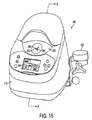
図15は、本発明の一実施形態によるボトル-シリンジウォーマ300内に置かれたライナ200の一例を示す斜視図であり、ボトル-シリンジウォーマが閉位置にあるところを示すものである。図15に示す乳児栄養物ウォーミング装置300は、乳児栄養物ウォーミング装置300をIVポールに取付けるのに使用される、ハウジング316に取付けられる取付け機構302を有している。ディスプレイ360は、乳児栄養物のユーザセッティングおよび現在の状態を示している。乳児栄養物ウォーミング装置300には、ライナが取付けられたときにのみ作動することを確保するライナ存在センサを設けることができる。
FIG. 15 is a perspective view illustrating an example of a
図16は、図15のボトル-シリンジウォーマ300のA-A線に沿う断面図である。乳児栄養物ウォーミング装置300は、少なくとも1つのヒータ310と、ファン312と、ベント機構314と、ハウジング316と、リッド318と、少なくとも1つのヒンジ320と、上方ダクト330と、下方ダクト340と、チャンバ350と、ディスプレイ360と、電源370とを有している。ハウジング316は更に、ハウジングリップ315を有している。
16 is a cross-sectional view taken along line AA of the bottle-syringe warmer 300 of FIG. The infant
作動に際し、ハウジング316のリッド318を開いて、チャンバ350を露出させる。ライナ200は、図16に示すように、リム部分240をハウジングリップ315上に取付けることにより、チャンバ350内に置かれる。次に、容器が開口230を通ってライナ内部に挿入される。リッド318が閉位置(閉位置は図15および図16に示されている)に戻され、ライナ200の開口230がカバーされる。容器がライナ内に入れられていない場合には、図示のようにシリンジのような容器380が、該容器の液体収容部分がチャンバ350内に確実に入るようにして、ポート262を通して配置される。他の形態では、容器380がシリンジではなく、当該分野で使用される多数の他の容器を使用できる。一例として、容器380は小瓶でもよい。
In operation, the
容器は、1つ以上の側面、頂および底を有している。ライナ200はこの中に容器を受入れることができるサイズを有し、容器の側面(単一または複数)をライナ200の側面(単一または複数)から隔てることができ、このため、ライナ200を通る空気流が容器の側面(単一または複数)の周囲を通ることができ、容器の周囲の空気を移動させる。
The container has one or more sides, a top and a bottom. The
図16には、空気流の経路が矢印390で示されている。ファン312がヒータ310を通して空気を移動させ、空気を有効に加熱する。或いは、ファン312により移動される空気を冷却する冷却装置を設けることができる。空気は、次に、導管構造すなわち、上方ダクト330および下方ダクト340を通って流れ、ライナ200内に流入する。空気は容器380の周囲に強制的に送られ、容器の周囲の空気を移動させる。次に、空気はファン312を通って上方に移動される。空気は、ベント機構314を通ってシステムを出入りする。
In FIG. 16, the air flow path is indicated by an
作動中にボトルまたはシリンジ内のミルクを振動または混合させる運動機構を設けることができる。この運動機構の利益は、ミルク成分を均質に維持し、熱伝達を補助し、かつウォーミングプロセスをピードアップすることである。この運動は、シェーカまたは軌道ミキサ等の機械的システムにより伝達される。また、この運動は、熱伝達に既に使用された容器上での空気循環によっても伝達される。 A motion mechanism can be provided that causes the milk in the bottle or syringe to vibrate or mix during operation. The benefits of this movement mechanism are to keep the milk components homogeneous, assist heat transfer and speed up the warming process. This motion is transmitted by a mechanical system such as a shaker or orbital mixer. This motion is also transmitted by air circulation over the container already used for heat transfer.
以上、本発明の種々の例示実施形態を説明したが、当業者ならば、本発明の範囲および精神から逸脱することなく、これらの実施形態に変更を加えることができるであろう。また、上記実施形態は例示を意味し、限定するものではないことに留意すべきである。すなわち、本発明の幾つかの実施形態には他の特徴および/または異なる特徴が存在する。 While various exemplary embodiments of the invention have been described above, those skilled in the art will be able to make changes to these embodiments without departing from the scope and spirit of the invention. It should also be noted that the above embodiments are meant to be illustrative and not limiting. That is, there are other features and / or different features in some embodiments of the invention.
100 ボトル-シリンジウォーマ
110 ヒータ
116 ハウジング
118 第1リッド
126 アクセスポート
128 第2リッド
130 孔(オリフィス)
136 チャンバ
143 切除部
146 ライナ
152 挿通体
100 bottle-syringe warmer 110
Claims (21)
該ハウジングの一部としてのヒータと、
ハウジング内に形成されたチャンバと、を有し、該チャンバはチャンバ内部への開口を備え、
ハウジングの一部としての導管構造を有し、該導管構造は、空気流を、ヒータにより加熱するためにチャンバへの入口に運び、次にチャンバに通し、次に出口を通してチャンバから排出し、
導管構造およびチャンバを通して空気流を移動させる装置と、
使用時にチャンバを閉じ、かつチャンバ内部にアクセスして、チャンバ内部で温める容器を置くために開くことができるチャンバ用リッドと、
着脱可能なライナと、を有し、
このライナは前記チャンバ内に置くことができ、前記入口から空気流を受入れかつ前記出口と連通しており、前記容器は、ライナがチャンバ内に置かれたときに空気流がライナを通って移動するようにしてライナ内に配置され、
前記リッドは、更にリッドポートを備え、このリッドポートを介してチャンバ内部にアクセスでき、前記リッドは、閉位置において前記開口上に位置し、前記リッドポートは、このリッドポートを介して栄養物容器を受け入れることができることを特徴とする乳児栄養物ウォーミング装置。 A housing;
A heater as part of the housing;
Anda the chamber formed within the housing, the chamber is provided with an opening to the interior chamber,
Has a conduit structure as part of the housing, the conduit structure, the air flow carries the entrance to the chamber for heating by the heater, then passed through a chamber, and then discharged from the chamber through the outlet,
An apparatus for moving the air flow through the conduit structure and the chamber;
Close the chamber in use, and to access the internal chamber, and a chamber lid that can be opened to put the vessel warmed inside the chamber,
A removable liner, and
The liner can be placed in the chamber, receives air flow from the inlet and is in communication with the outlet, and the container moves the air flow through the liner when the liner is placed in the chamber. so as to be disposed within the liner,
The lid further comprises a lid port through which the chamber interior can be accessed, the lid being positioned over the opening in a closed position, the lid port being a nutrient container via the lid port. infant nutrition warming device according to claim Rukoto can accept.
乳児用栄養物が入れられた容器をチャンバ内部に置く段階と、
ウォーミングシーケンスに関するユーザの入力を受入れるコントローラを装置に設ける段階と、
ウォーミングシーケンスのパラメータをコントローラに入力する段階と、
前記液体栄養物を所望温度に温めるべく、空気を加熱しかつ加熱された空気をチャンバを通して循環させる段階と、を更に有することを特徴とする乳児栄養物を加熱する方法。 Providing a warming device having a warming element for heating air and a chamber with an interior for receiving and warming a container containing infant nutrition, wherein the warming device supplies the warmed air to the warming device; A conduit structure for carrying through the interior of the chamber, the chamber comprising a lid for opening and closing the interior of the chamber, the lid further comprising a lid port through which the chamber interior can be accessed, the lid being in the closed position Located on the opening, the lid port can receive a nutrient container via the lid port;
Placing a container with infant nutrition inside the chamber;
Providing the device with a controller that accepts user input regarding the warming sequence;
Inputting the parameters of the warming sequence into the controller;
Method of heating the to warm the liquid nutrient to a desired temperature, infant nutrition, characterized by further comprising the steps of circulating air is heated and the heated air through the chamber.
Applications Claiming Priority (5)
| Application Number | Priority Date | Filing Date | Title |
|---|---|---|---|
| US6618608P | 2008-02-19 | 2008-02-19 | |
| US61/066,186 | 2008-02-19 | ||
| US12/371,834 US9241596B2 (en) | 2008-02-19 | 2009-02-16 | Breastmilk handling apparatus |
| US12/371,834 | 2009-02-16 | ||
| PCT/US2009/034303 WO2009105428A2 (en) | 2008-02-19 | 2009-02-17 | Breastmilk handling apparatus particularly useful for warming of breastmilk containers such as bottles and syringes |
Publications (3)
| Publication Number | Publication Date |
|---|---|
| JP2011512231A JP2011512231A (en) | 2011-04-21 |
| JP2011512231A5 JP2011512231A5 (en) | 2012-04-05 |
| JP5518746B2 true JP5518746B2 (en) | 2014-06-11 |
Family
ID=40955222
Family Applications (1)
| Application Number | Title | Priority Date | Filing Date |
|---|---|---|---|
| JP2010547711A Active JP5518746B2 (en) | 2008-02-19 | 2009-02-17 | Breast milk handling device especially effective for warming breast milk containers such as bottles and syringes |
Country Status (9)
| Country | Link |
|---|---|
| US (3) | US9241596B2 (en) |
| EP (3) | EP2249686B1 (en) |
| JP (1) | JP5518746B2 (en) |
| CN (2) | CN102006807B (en) |
| AU (3) | AU2009215636B2 (en) |
| CA (1) | CA2716024A1 (en) |
| ES (1) | ES2581846T3 (en) |
| PL (2) | PL2249686T3 (en) |
| WO (1) | WO2009105428A2 (en) |
Families Citing this family (14)
| Publication number | Priority date | Publication date | Assignee | Title |
|---|---|---|---|---|
| US9241596B2 (en) * | 2008-02-19 | 2016-01-26 | Medela Holding Ag | Breastmilk handling apparatus |
| USD761647S1 (en) * | 2009-02-16 | 2016-07-19 | Medela Holding Ag | Liner for containers |
| NL2007327C2 (en) * | 2011-09-01 | 2013-03-04 | Nyambe B V | Heating apparatus for thermoplastic obturator. |
| WO2015173042A1 (en) * | 2014-05-14 | 2015-11-19 | Koninklijke Philips N.V. | Heating device for heating food in a container, in particular milk in a baby bottle |
| RU2643418C1 (en) | 2014-11-11 | 2018-02-01 | Конинклейке Филипс Н.В. | Beverage and food temperature control |
| CN105410154A (en) * | 2015-11-20 | 2016-03-23 | 李晓勤 | Quick-frozen food unfreezing device |
| CA3031253A1 (en) * | 2016-07-21 | 2018-01-25 | Clinical Biotechnology Research Institute At Rsfh | Container tracking system |
| WO2018108814A1 (en) | 2016-12-15 | 2018-06-21 | Medela Holding Ag | Device for controlling the temperature of baby food |
| US10934152B2 (en) | 2017-04-07 | 2021-03-02 | Greg Swears | Fluid dispenser |
| USD831402S1 (en) | 2017-07-21 | 2018-10-23 | Medela Holding Ag | Breastmilk warmer |
| AU2019202204B1 (en) * | 2019-03-18 | 2020-10-01 | Jining Beila Lamps Co., Ltd. | A cup that can hold water of different temperatures |
| US11363908B2 (en) | 2019-09-17 | 2022-06-21 | Baby Brezza Enterprises LLC | Baby bottle warmer and mixer |
| CN111166193B (en) * | 2020-03-09 | 2021-05-04 | 中国人民解放军陆军特色医学中心 | Mobile constant-temperature milk storage device and working method thereof |
| CN113243750B (en) * | 2021-06-03 | 2022-08-23 | 广东智源机器人科技有限公司 | Food cooking equipment |
Family Cites Families (91)
| Publication number | Priority date | Publication date | Assignee | Title |
|---|---|---|---|---|
| US1865472A (en) * | 1928-06-06 | 1932-07-05 | Lamstein Irving | Test tube heating apparatus |
| US2090666A (en) * | 1936-08-31 | 1937-08-24 | Benjamin M Copeland | Heater for scalp solutions |
| US2187196A (en) * | 1938-07-12 | 1940-01-16 | Samuel H Douglass | Lunch box |
| US2292992A (en) * | 1941-05-08 | 1942-08-11 | Crouch William Lawrence | Heating device |
| US2413176A (en) * | 1945-02-02 | 1946-12-24 | Emsley T Deaton | Milk bottle heater |
| US2428996A (en) * | 1945-03-07 | 1947-10-14 | Jr Louis Schworm | Electric food warmer |
| US2584435A (en) * | 1946-11-30 | 1952-02-05 | Norman B Doerr | Baby supply cabinet |
| US2595685A (en) * | 1949-04-25 | 1952-05-06 | Robert E Mallory | Infant milk bottle and food warmer |
| US2583118A (en) * | 1949-06-22 | 1952-01-22 | Francis E Porambo | Portable hot food cabinet |
| US2653214A (en) * | 1951-02-16 | 1953-09-22 | A A Morgan | Electric test bottle bath |
| US2654018A (en) * | 1951-05-19 | 1953-09-29 | Sandberg Nicolay Bugge | Electrically heated steam-bath stove |
| US2644072A (en) * | 1951-10-02 | 1953-06-30 | Violet J Aruth | Dispenser |
| US2713112A (en) * | 1953-03-19 | 1955-07-12 | Lurline M Mills | Bottle or container warmer |
| US2853205A (en) * | 1956-04-12 | 1958-09-23 | Marjorie M Boyd | Bottled milk cooler and warmer and conveying means therefor |
| US2932718A (en) * | 1957-06-25 | 1960-04-12 | Thomas D Kinney | Test tube warmer |
| US3345497A (en) * | 1963-12-23 | 1967-10-03 | R Dental Products Inc Van | Electric water bath heater for conditioning hydrocolloids |
| US3346883A (en) * | 1965-10-21 | 1967-10-17 | Louise Sandler | Receptacles |
| US3511241A (en) * | 1966-06-23 | 1970-05-12 | John W Lee | Incontinence device for the male patient |
| US3607134A (en) * | 1968-10-02 | 1971-09-21 | Delbert D Mcintyre | Sample holder for maintaining blood samples at a preselected temperature |
| US3634651A (en) * | 1970-12-04 | 1972-01-11 | Becton Dickinson Co | Serological incubator |
| US3780794A (en) * | 1971-12-02 | 1973-12-25 | B Staub | Food table |
| US3801278A (en) * | 1972-03-13 | 1974-04-02 | Sybron Corp | Sterilizing apparatus for hydrophilic contact lenses |
| US3902043A (en) * | 1973-07-19 | 1975-08-26 | Virgil Kenneth Rogan | Appliance for heating and applying dental wax |
| FR2244397B1 (en) * | 1973-09-25 | 1978-06-23 | Etud Sa | |
| US3855451A (en) * | 1974-05-02 | 1974-12-17 | Lincoln Mfg Co | Food heating and warming cabinet |
| US3999601A (en) * | 1974-06-19 | 1976-12-28 | Owens-Illinois, Inc. | Food service tray |
| US4038968A (en) * | 1975-06-03 | 1977-08-02 | Alfred Rovell | Air screen for food warming table |
| US4037081A (en) * | 1976-06-21 | 1977-07-19 | Aldridge Bobby V | Electro-lunch bucket |
| US4163471A (en) * | 1976-09-30 | 1979-08-07 | Frederic Leder | Forced convection heat exchanger for warming articles |
| US4215843A (en) * | 1978-02-17 | 1980-08-05 | Mattel, Inc. | Toy molding apparatus and material for use therewith |
| DE2813145C3 (en) * | 1978-03-25 | 1981-04-23 | Melitta-Werke Bentz & Sohn, 4950 Minden | Device for thawing frozen food |
| US4233495A (en) * | 1978-12-15 | 1980-11-11 | Lincoln Manufacturing Company, Inc. | Food warming cabinet |
| US4256697A (en) * | 1978-12-21 | 1981-03-17 | Fred Baldwin | Blood incubator device |
| US4273992A (en) * | 1979-12-13 | 1981-06-16 | Thomas Arend J | Electric heating apparatus for heat-treating pharmaceuticals |
| DE3010889A1 (en) | 1980-03-21 | 1981-10-01 | Devappa Dr.Ing. R. Zinsser & Ing. K. Prestl, 8420 Kelheim | DEVICE FOR HEATING FOODS CONTAINED IN CONTENTS |
| US4364234A (en) * | 1981-03-25 | 1982-12-21 | Koolatron Industries, Ltd. | Control circuitry for thermoelectric environmental chamber |
| US4328676A (en) * | 1981-03-25 | 1982-05-11 | Koolatron Industries, Ltd. | Thermoelectric environmental chamber |
| US4423819A (en) * | 1981-08-19 | 1984-01-03 | U.S. Clinical Products, Inc. | Flexible sterile closure system for containers |
| US4390104A (en) * | 1981-08-19 | 1983-06-28 | U.S. Clinical Products, Inc. | Flexible plastic sterile closure system for containers |
| US4597435A (en) * | 1985-01-09 | 1986-07-01 | Fosco Jr Benjamin P | Bottle warmer or cooler |
| US4598834A (en) * | 1985-02-06 | 1986-07-08 | U.S. Clinical Products, Inc. | Flexible sterile closure system for a container with a side injection port |
| US4923681A (en) * | 1986-10-03 | 1990-05-08 | Archeraire Industries, Inc. | High velocity hot air sterilization device with controller |
| US5057671A (en) * | 1989-08-07 | 1991-10-15 | Colson Charles R | Solution warming unit |
| US4966303A (en) * | 1989-08-07 | 1990-10-30 | Jones August C | Insulated beverage container securement apparatus |
| US4954149A (en) * | 1989-10-25 | 1990-09-04 | Merlin Instrument Company | Injection septum |
| US5183994A (en) * | 1990-10-26 | 1993-02-02 | Bowles Sr Dale D | Heated drug box |
| US5195976A (en) * | 1990-12-12 | 1993-03-23 | Houston Advanced Research Center | Intravenous fluid temperature regulation method and apparatus |
| US5108372A (en) * | 1990-12-12 | 1992-04-28 | Houston Advanced Research Center | Intravenous fluid temperature regulation method and apparatus |
| US5211181A (en) * | 1991-05-17 | 1993-05-18 | Martek Corporation | Apparatus and method for collecting human breath samples |
| US5243833A (en) * | 1991-11-08 | 1993-09-14 | Instacool Inc. Of North America | Device for thawing frozen transfusion material and method therefore |
| US5248870A (en) * | 1991-12-20 | 1993-09-28 | Marlyn Redal | Electric heating device for warming the contents of bottles or other containers |
| US5408576A (en) * | 1992-10-28 | 1995-04-18 | Bishop; Robert A. | IV fluid warmer |
| US5397875A (en) * | 1992-11-24 | 1995-03-14 | Bechtold, Jr.; Joseph A. | Portable appliance for heating towels and for dispensing heated fluid such as body oil to facilitate the administration of a massage |
| US5399007A (en) * | 1993-04-15 | 1995-03-21 | Reliance Medical Products, Inc. | Medical treatment cabinet |
| US5954431A (en) * | 1994-12-01 | 1999-09-21 | Laser Substrates, Inc. | Transparent security pocket compatible with non-impact printers |
| US5410130A (en) * | 1994-04-20 | 1995-04-25 | Ericomp, Inc. | Heating and temperature cycling |
| US5544701A (en) * | 1994-07-19 | 1996-08-13 | Elder; Roy W. | Canister warming apparatus |
| US5531810A (en) | 1994-09-21 | 1996-07-02 | Merlin Instrument Company | Injection septum with dust wiper |
| US5661978A (en) * | 1994-12-09 | 1997-09-02 | Pyxis Corporation | Medical dispensing drawer and thermoelectric device for cooling the contents therein |
| US5786573A (en) * | 1995-07-07 | 1998-07-28 | Fabrikant; Marvin | Heater for shaving cream containers enabling vertical adjustment of the heater relative to the container |
| US5817146A (en) | 1995-11-09 | 1998-10-06 | Augustine Medical, Inc. | Patient warming system with IV fluid warmer |
| US5628309A (en) * | 1996-01-25 | 1997-05-13 | Raya Systems, Inc. | Meter for electrically measuring and recording injection syringe doses |
| US6467953B1 (en) * | 1999-03-30 | 2002-10-22 | Medical Solutions, Inc. | Method and apparatus for monitoring temperature of intravenously delivered fluids and other medical items |
| US6768085B2 (en) * | 2001-07-02 | 2004-07-27 | Medical Solutions, Inc. | Medical solution warming system and method of heating and maintaining medical solutions at desired temperatures |
| CA2286331A1 (en) | 1997-04-07 | 1998-10-15 | Calvin Blankenship | Warming system and method for heating various items utilized in surgical procedures |
| US5913844A (en) * | 1997-06-17 | 1999-06-22 | Liebel-Flarsheim Company | Power injector and method providing removal of used disposable syringe |
| US5924303A (en) * | 1998-03-09 | 1999-07-20 | California Innovations Inc. | Insulated soft-sided portable case having externally accessible receptacle |
| US6605475B1 (en) * | 1999-04-16 | 2003-08-12 | Perspective Biosystems, Inc. | Apparatus and method for sample delivery |
| US20010035413A1 (en) * | 2000-05-01 | 2001-11-01 | Douglas Thai | Non-spill container |
| US6234165B1 (en) * | 2000-08-28 | 2001-05-22 | Kevin A. Creighton | Baby bottle warmer |
| WO2002031417A1 (en) | 2000-10-10 | 2002-04-18 | John Granville Perrins | Storage device for drink containers |
| US6417498B1 (en) * | 2001-04-12 | 2002-07-09 | Janice M. Shields | Neonatal substrate warmer |
| US6444956B1 (en) * | 2001-07-23 | 2002-09-03 | Elizabeth Witcher | Hand lotion warmer |
| US6871751B2 (en) * | 2001-10-19 | 2005-03-29 | The Goodyear Tire & Rubber Company | Rubber for baby bottle nipples, pacifiers, & syringe plungers |
| US6617552B1 (en) | 2002-09-16 | 2003-09-09 | Randall Wade Taylor | System and method for warming premature infant feedings |
| US6847013B2 (en) * | 2003-02-10 | 2005-01-25 | Metal Masters Foodservice | Heated proofing cabinet |
| US6870137B1 (en) * | 2003-03-11 | 2005-03-22 | Michael G. Clapp | Artificial tears container warming apparatus |
| US6809302B1 (en) * | 2003-05-27 | 2004-10-26 | Demarch R. Jones | Bottle warming device |
| US7776008B2 (en) * | 2003-08-08 | 2010-08-17 | Playtex Products, Inc. | Manual breast pump |
| GB2439093A (en) | 2003-09-30 | 2007-12-19 | Stefano Milazzo | Comestible Preparation Apparatus |
| US6897413B1 (en) * | 2004-03-29 | 2005-05-24 | Brain Power Incorporated | Device for heating dyes to tint optical lenses and filters |
| KR100645158B1 (en) * | 2005-02-22 | 2006-11-10 | 주식회사 대우일렉트로닉스 | Multi function storage for an infant |
| US7158717B2 (en) * | 2005-04-07 | 2007-01-02 | Frank Young | Apparatus for altering a temperature state of a liquid within a container and method of use |
| RU2314844C2 (en) | 2005-07-20 | 2008-01-20 | Общество с ограниченной ответственностью "Дипольные структуры" | Method for stimulating basic biochemical reactions in organism for carrying out treatment and tissue recovery, panel for carrying out treatment and tissue recovery and radiator |
| US7988675B2 (en) * | 2005-12-08 | 2011-08-02 | West Pharmaceutical Services Of Delaware, Inc. | Automatic injection and retraction devices for use with pre-filled syringe cartridges |
| US20070280657A1 (en) * | 2006-05-31 | 2007-12-06 | Jennifer Loia | Baby bottle/food warmer |
| US20080087659A1 (en) * | 2006-10-16 | 2008-04-17 | Norman Scott A | Neonatal nutrition warmer |
| US20080093357A1 (en) * | 2006-10-16 | 2008-04-24 | Norman Scott A | Neonatal Nutrition Warmer |
| JP5221654B2 (en) * | 2007-07-09 | 2013-06-26 | サーモダイン フードサービス プロダクツ、インコーポレーテッド | Product heating device |
| US8087528B1 (en) * | 2008-01-28 | 2012-01-03 | Elizabeth Scarlett | Stabilizer cup holder |
| US9241596B2 (en) * | 2008-02-19 | 2016-01-26 | Medela Holding Ag | Breastmilk handling apparatus |
-
2009
- 2009-02-16 US US12/371,834 patent/US9241596B2/en active Active
- 2009-02-17 WO PCT/US2009/034303 patent/WO2009105428A2/en active Application Filing
- 2009-02-17 EP EP09713434.0A patent/EP2249686B1/en active Active
- 2009-02-17 ES ES11154354.2T patent/ES2581846T3/en active Active
- 2009-02-17 EP EP11154354.2A patent/EP2316313B1/en active Active
- 2009-02-17 CN CN200980113612.9A patent/CN102006807B/en active Active
- 2009-02-17 PL PL09713434T patent/PL2249686T3/en unknown
- 2009-02-17 CA CA2716024A patent/CA2716024A1/en not_active Abandoned
- 2009-02-17 AU AU2009215636A patent/AU2009215636B2/en active Active
- 2009-02-17 PL PL11154354.2T patent/PL2316313T3/en unknown
- 2009-02-17 CN CN201610138041.6A patent/CN106037497B/en active Active
- 2009-02-17 JP JP2010547711A patent/JP5518746B2/en active Active
- 2009-02-17 EP EP11154280A patent/EP2316314A3/en not_active Withdrawn
-
2014
- 2014-08-27 US US14/470,446 patent/US10327585B2/en active Active
- 2014-09-05 US US14/479,255 patent/US10136759B2/en active Active
-
2016
- 2016-02-11 AU AU2016200887A patent/AU2016200887B2/en active Active
-
2017
- 2017-09-27 AU AU2017235942A patent/AU2017235942A1/en not_active Abandoned
Also Published As
| Publication number | Publication date |
|---|---|
| US10136759B2 (en) | 2018-11-27 |
| WO2009105428A2 (en) | 2009-08-27 |
| EP2316314A3 (en) | 2012-01-18 |
| US20140374371A1 (en) | 2014-12-25 |
| CN102006807A (en) | 2011-04-06 |
| US20140376894A1 (en) | 2014-12-25 |
| PL2316313T3 (en) | 2016-10-31 |
| ES2581846T3 (en) | 2016-09-07 |
| EP2316314A2 (en) | 2011-05-04 |
| US10327585B2 (en) | 2019-06-25 |
| AU2016200887A1 (en) | 2016-03-03 |
| AU2009215636B2 (en) | 2016-02-25 |
| EP2316313B1 (en) | 2016-04-20 |
| US20090208193A1 (en) | 2009-08-20 |
| PL2249686T3 (en) | 2015-06-30 |
| CN102006807B (en) | 2016-04-13 |
| AU2017235942A1 (en) | 2017-10-19 |
| AU2016200887B2 (en) | 2017-10-12 |
| EP2316313A2 (en) | 2011-05-04 |
| JP2011512231A (en) | 2011-04-21 |
| WO2009105428A3 (en) | 2010-03-11 |
| CN106037497A (en) | 2016-10-26 |
| EP2249686A2 (en) | 2010-11-17 |
| EP2316313A3 (en) | 2012-03-28 |
| US9241596B2 (en) | 2016-01-26 |
| CA2716024A1 (en) | 2009-08-27 |
| AU2009215636A1 (en) | 2009-08-27 |
| CN106037497B (en) | 2019-07-23 |
| EP2249686B1 (en) | 2014-11-19 |
Similar Documents
| Publication | Publication Date | Title |
|---|---|---|
| JP5518746B2 (en) | Breast milk handling device especially effective for warming breast milk containers such as bottles and syringes | |
| US10729149B2 (en) | Thawing of raw milk | |
| US20080093357A1 (en) | Neonatal Nutrition Warmer | |
| US10292908B2 (en) | Neonatal enteral feeding system | |
| US20080087659A1 (en) | Neonatal nutrition warmer | |
| EP3337364A1 (en) | Modular baby food preparation device | |
| US6617552B1 (en) | System and method for warming premature infant feedings | |
| DK1867355T3 (en) | System for photo irradiation of blood or fractions thereof, and the procedure thereof | |
| TWI812722B (en) | Liquid administering device, liquid container, method for administering liquid, and sanitizing device | |
| US20040076409A1 (en) | System and method for warming premature infant feedings | |
| US20150164270A1 (en) | Sanitary Bag System for Warming Nutritional Liquid for Neonates |
Legal Events
| Date | Code | Title | Description |
|---|---|---|---|
| A521 | Request for written amendment filed |
Free format text: JAPANESE INTERMEDIATE CODE: A523 Effective date: 20120216 |
|
| A621 | Written request for application examination |
Free format text: JAPANESE INTERMEDIATE CODE: A621 Effective date: 20120216 |
|
| A977 | Report on retrieval |
Free format text: JAPANESE INTERMEDIATE CODE: A971007 Effective date: 20130411 |
|
| A131 | Notification of reasons for refusal |
Free format text: JAPANESE INTERMEDIATE CODE: A131 Effective date: 20130424 |
|
| A601 | Written request for extension of time |
Free format text: JAPANESE INTERMEDIATE CODE: A601 Effective date: 20130724 |
|
| A602 | Written permission of extension of time |
Free format text: JAPANESE INTERMEDIATE CODE: A602 Effective date: 20130731 |
|
| A521 | Request for written amendment filed |
Free format text: JAPANESE INTERMEDIATE CODE: A523 Effective date: 20131023 |
|
| TRDD | Decision of grant or rejection written | ||
| A01 | Written decision to grant a patent or to grant a registration (utility model) |
Free format text: JAPANESE INTERMEDIATE CODE: A01 Effective date: 20140312 |
|
| A61 | First payment of annual fees (during grant procedure) |
Free format text: JAPANESE INTERMEDIATE CODE: A61 Effective date: 20140402 |
|
| R150 | Certificate of patent or registration of utility model |
Ref document number: 5518746 Country of ref document: JP Free format text: JAPANESE INTERMEDIATE CODE: R150 |
|
| R250 | Receipt of annual fees |
Free format text: JAPANESE INTERMEDIATE CODE: R250 |
|
| R250 | Receipt of annual fees |
Free format text: JAPANESE INTERMEDIATE CODE: R250 |
|
| R250 | Receipt of annual fees |
Free format text: JAPANESE INTERMEDIATE CODE: R250 |
|
| R250 | Receipt of annual fees |
Free format text: JAPANESE INTERMEDIATE CODE: R250 |
|
| R250 | Receipt of annual fees |
Free format text: JAPANESE INTERMEDIATE CODE: R250 |
|
| R250 | Receipt of annual fees |
Free format text: JAPANESE INTERMEDIATE CODE: R250 |
|
| R250 | Receipt of annual fees |
Free format text: JAPANESE INTERMEDIATE CODE: R250 |