JP5517618B2 - Head for affixing carbon fiber strip and affixing method - Google Patents
Head for affixing carbon fiber strip and affixing method Download PDFInfo
- Publication number
- JP5517618B2 JP5517618B2 JP2009523309A JP2009523309A JP5517618B2 JP 5517618 B2 JP5517618 B2 JP 5517618B2 JP 2009523309 A JP2009523309 A JP 2009523309A JP 2009523309 A JP2009523309 A JP 2009523309A JP 5517618 B2 JP5517618 B2 JP 5517618B2
- Authority
- JP
- Japan
- Prior art keywords
- strip
- head
- carbon fiber
- strips
- supply
- Prior art date
- Legal status (The legal status is an assumption and is not a legal conclusion. Google has not performed a legal analysis and makes no representation as to the accuracy of the status listed.)
- Expired - Fee Related
Links
Images


Classifications
-
- B—PERFORMING OPERATIONS; TRANSPORTING
- B29—WORKING OF PLASTICS; WORKING OF SUBSTANCES IN A PLASTIC STATE IN GENERAL
- B29C—SHAPING OR JOINING OF PLASTICS; SHAPING OF MATERIAL IN A PLASTIC STATE, NOT OTHERWISE PROVIDED FOR; AFTER-TREATMENT OF THE SHAPED PRODUCTS, e.g. REPAIRING
- B29C70/00—Shaping composites, i.e. plastics material comprising reinforcements, fillers or preformed parts, e.g. inserts
- B29C70/04—Shaping composites, i.e. plastics material comprising reinforcements, fillers or preformed parts, e.g. inserts comprising reinforcements only, e.g. self-reinforcing plastics
- B29C70/28—Shaping operations therefor
- B29C70/30—Shaping by lay-up, i.e. applying fibres, tape or broadsheet on a mould, former or core; Shaping by spray-up, i.e. spraying of fibres on a mould, former or core
- B29C70/38—Automated lay-up, e.g. using robots, laying filaments according to predetermined patterns
- B29C70/386—Automated tape laying [ATL]
- B29C70/388—Tape placement heads, e.g. component parts, details or accessories
-
- B—PERFORMING OPERATIONS; TRANSPORTING
- B29—WORKING OF PLASTICS; WORKING OF SUBSTANCES IN A PLASTIC STATE IN GENERAL
- B29C—SHAPING OR JOINING OF PLASTICS; SHAPING OF MATERIAL IN A PLASTIC STATE, NOT OTHERWISE PROVIDED FOR; AFTER-TREATMENT OF THE SHAPED PRODUCTS, e.g. REPAIRING
- B29C53/00—Shaping by bending, folding, twisting, straightening or flattening; Apparatus therefor
- B29C53/80—Component parts, details or accessories; Auxiliary operations
-
- B—PERFORMING OPERATIONS; TRANSPORTING
- B29—WORKING OF PLASTICS; WORKING OF SUBSTANCES IN A PLASTIC STATE IN GENERAL
- B29C—SHAPING OR JOINING OF PLASTICS; SHAPING OF MATERIAL IN A PLASTIC STATE, NOT OTHERWISE PROVIDED FOR; AFTER-TREATMENT OF THE SHAPED PRODUCTS, e.g. REPAIRING
- B29C70/00—Shaping composites, i.e. plastics material comprising reinforcements, fillers or preformed parts, e.g. inserts
- B29C70/04—Shaping composites, i.e. plastics material comprising reinforcements, fillers or preformed parts, e.g. inserts comprising reinforcements only, e.g. self-reinforcing plastics
- B29C70/28—Shaping operations therefor
- B29C70/30—Shaping by lay-up, i.e. applying fibres, tape or broadsheet on a mould, former or core; Shaping by spray-up, i.e. spraying of fibres on a mould, former or core
- B29C70/38—Automated lay-up, e.g. using robots, laying filaments according to predetermined patterns
-
- B—PERFORMING OPERATIONS; TRANSPORTING
- B29—WORKING OF PLASTICS; WORKING OF SUBSTANCES IN A PLASTIC STATE IN GENERAL
- B29C—SHAPING OR JOINING OF PLASTICS; SHAPING OF MATERIAL IN A PLASTIC STATE, NOT OTHERWISE PROVIDED FOR; AFTER-TREATMENT OF THE SHAPED PRODUCTS, e.g. REPAIRING
- B29C70/00—Shaping composites, i.e. plastics material comprising reinforcements, fillers or preformed parts, e.g. inserts
- B29C70/04—Shaping composites, i.e. plastics material comprising reinforcements, fillers or preformed parts, e.g. inserts comprising reinforcements only, e.g. self-reinforcing plastics
- B29C70/28—Shaping operations therefor
- B29C70/54—Component parts, details or accessories; Auxiliary operations, e.g. feeding or storage of prepregs or SMC after impregnation or during ageing
- B29C70/545—Perforating, cutting or machining during or after moulding
-
- Y—GENERAL TAGGING OF NEW TECHNOLOGICAL DEVELOPMENTS; GENERAL TAGGING OF CROSS-SECTIONAL TECHNOLOGIES SPANNING OVER SEVERAL SECTIONS OF THE IPC; TECHNICAL SUBJECTS COVERED BY FORMER USPC CROSS-REFERENCE ART COLLECTIONS [XRACs] AND DIGESTS
- Y10—TECHNICAL SUBJECTS COVERED BY FORMER USPC
- Y10T—TECHNICAL SUBJECTS COVERED BY FORMER US CLASSIFICATION
- Y10T156/00—Adhesive bonding and miscellaneous chemical manufacture
- Y10T156/12—Surface bonding means and/or assembly means with cutting, punching, piercing, severing or tearing
- Y10T156/1348—Work traversing type
-
- Y—GENERAL TAGGING OF NEW TECHNOLOGICAL DEVELOPMENTS; GENERAL TAGGING OF CROSS-SECTIONAL TECHNOLOGIES SPANNING OVER SEVERAL SECTIONS OF THE IPC; TECHNICAL SUBJECTS COVERED BY FORMER USPC CROSS-REFERENCE ART COLLECTIONS [XRACs] AND DIGESTS
- Y10—TECHNICAL SUBJECTS COVERED BY FORMER USPC
- Y10T—TECHNICAL SUBJECTS COVERED BY FORMER US CLASSIFICATION
- Y10T156/00—Adhesive bonding and miscellaneous chemical manufacture
- Y10T156/17—Surface bonding means and/or assemblymeans with work feeding or handling means
Landscapes
- Engineering & Computer Science (AREA)
- Mechanical Engineering (AREA)
- Chemical & Material Sciences (AREA)
- Composite Materials (AREA)
- Robotics (AREA)
- Moulding By Coating Moulds (AREA)
- Reinforced Plastic Materials (AREA)
Description
本発明は、炭素繊維のストリップを貼り付けることによる部品の製造、特に航空産業用の部品の製造に関連し、複数のストリップを備えた貼り付け用ヘッドとの関連で特有の特徴を有する装置及び被形成面に前記ストリップを貼り付けるための貼り付け方法を提案する。 The present invention relates to the manufacture of parts by applying carbon fiber strips, in particular to the manufacture of parts for the aviation industry, and an apparatus having unique features in connection with an application head comprising a plurality of strips and A pasting method for pasting the strip on the surface to be formed is proposed.
航空構造物の構造では、構成部品間の継ぎ目は最も耐久性が必要な部分であり、それにより、継ぎ目の数を減らすためにできるだけ大きな部品が使用される傾向にある。 In the structure of an aeronautical structure, the seams between the components are the parts that need the most durability, so that the largest possible part tends to be used to reduce the number of seams.
しかしながら、部品のサイズが大きくなると同時にその複雑さが増し、大きな部品の複雑な条件に適用される品質を満たすことができる機械が必要とされる。 However, there is a need for a machine that can meet the quality that is applied to the complex conditions of large parts as the size of the parts increases and at the same time increases in complexity.
例えば、部品の表面の複雑さとしては備えている湾曲領域があり、この湾曲領域は、航空部品の製造で行われるように炭素繊維のストリップを積層することによって形成されるが、生じる湾曲半径は、貼り付けで使用される炭素繊維の帯の幅に依存するので問題が生じる。貼り付けられる帯の幅が大きいほど、貼り付けで生じる湾曲半径を大きくしなければならず、即ち、使用される帯のしわを防ぐためにより大きな半径が必要である。 For example, the complexity of the surface of a part has a curved area that is formed by laminating carbon fiber strips as is done in the manufacture of aviation parts, but the resulting radius of curvature is A problem arises because it depends on the width of the carbon fiber band used in the pasting. The larger the width of the band to be pasted, the larger the radius of curvature produced by the pasting, i.e., a larger radius is required to prevent wrinkling of the band used.
今までに知られているテープ積層装置と呼ばれるストリップを積層するヘッドでは、ヘッドは、異なる幅寸法(即ち、300、150又は75mm)を有する単一のストリップを貼り付けるが、常に同一のストリップを貼り付ける。 In heads that laminate strips known to date, called tape laminators, the head applies a single strip with different width dimensions (ie 300, 150 or 75 mm), but always applies the same strip. paste.
幅300mmのストリップで最も高い生産性が達成されるが、75mmのストリップでは、より小さい半径を有する湾曲を描くことができる。 The highest productivity is achieved with a 300 mm wide strip, but with a 75 mm strip a curve with a smaller radius can be drawn.
貼り付ける帯の幅は、炭素繊維のストリップ積層によって部品を形成する工程の生産性に比例的に作用し、貼り付け用のストリップの幅が小さいほど、実行しなければならないパス回数が増え、必要な時間が長くなって生産性が低下する。 The width of the band to be applied is proportional to the productivity of the process of forming parts by carbon fiber strip lamination, and the smaller the width of the strip for application, the more passes that must be performed. The longer the time, the lower the productivity.
更に、必要とされる機能を果たすために使用される貼り付け用ストリップの炭素繊維には樹脂が浸み込まされ、ストリップが製造用オートクレーブから出てからの持続期間は約10日であり、その期間中にストリップが使用されなければならなず、そうでない場合は破棄されなければならない。そのため、材料の経時劣化による損失をできるだけ少なくしストリップの迅速な使用を達成するためには、貼り付けの生産性が重要である。 Furthermore, the carbon fibers of the application strip used to perform the required function are impregnated with resin, and the duration of the strip from the production autoclave is about 10 days, The strip must be used during the period, otherwise it must be discarded. Therefore, in order to minimize loss due to aging of the material as much as possible and to achieve rapid use of the strip, the productivity of pasting is important.
同一の炭素繊維のストリップから積層するこれらのテープ積層装置とは別に、複数のリールに巻かれた細線により細い炭素繊維を使用するファイバ積層装置と呼ばれる他の装置が知られている。 In addition to these tape laminating apparatuses that laminate from the same carbon fiber strip, another apparatus called a fiber laminating apparatus that uses thin carbon fibers by thin wires wound around a plurality of reels is known.
本発明によれば、炭素繊維のストリップを貼り付けるヘッドが提案され、このヘッドにより、前記ストリップでのストリップの貼り付けによって大きくて複雑な部品の形成に関する問題を有利に解決することができる機能的特徴がもたらされる。 According to the present invention, a head for attaching a strip of carbon fiber is proposed, and with this head, the problem relating to the formation of large and complex parts can be advantageously solved by applying the strip on the strip. Features are brought about.
この装置によれば、ヘッドは、テープ積層装置のタイプ、即ち繊維積層装置スプールに巻かれた多数の炭素繊維ではなく、紙支持体上に巻かれた炭素繊維のストリップを使用するタイプである。しかし、ヘッドが同一の300、150又は75mmのストリップを使用する従来の手法と比べて、本発明の装置によれば、このヘッドは、それぞれ幅が75mmの少なくとも2つのストリップ、好ましくは4つの炭素繊維のストリップを使用し、ヘッドが同時に4つのストリップを貼り付ける場合に、標準の300mmの幅寸法に達し、最も高い生産性が提供され、ストリップにしわを生じることなく極めて小さい半径を描くことができる。これと対照的に、領域が湾曲しているとき、常に合計300mmのストリッピング幅を保って、その湾曲の半径によって2つの150mmのストリップを使用することができ、又は湾曲の半径がきわめて大きく部品が実質的に平坦な場合には、300mmの単一ストリップもまた使用することができる。 According to this apparatus, the head is of the type of tape laminator, that is, a type that uses a strip of carbon fibers wound on a paper support rather than multiple carbon fibers wound on a fiber laminator spool. However, compared to conventional approaches that use 300, 150 or 75 mm strips with the same head, according to the apparatus of the present invention, the head comprises at least two strips, preferably four carbons, each 75 mm wide. When using a strip of fiber and the head applies four strips simultaneously, the standard 300mm width dimension is reached, providing the highest productivity and drawing a very small radius without wrinkling the strip it can. In contrast, when the region is curved, it is possible to use two 150 mm strips depending on the radius of curvature, always keeping a total stripping width of 300 mm, or parts with a very large radius of curvature. If is substantially flat, a single 300 mm strip can also be used.
実際に、本発明品によれば、炭素繊維のストリップの少なくとも2つのリール、好ましくは4つのリールが配置された貼り付け用ヘッドが使用され、前記リールは、独立する連続した部分の構成により形成された主ローラに取り付けられる。これらの部分は、コンピュータ・プログラミングによって制御されたそれぞれの回転作動トランスミッションと連結される。被形成面上に炭素繊維のストリップが貼り付けられる時、従来の保護紙を備えたストリップが提供され、保護紙は、各リールの独立した巻き取りスプールに分離され収集されて、スプールに巻き付けられる。 In fact, according to the present invention, an affixing head is used in which at least two reels, preferably four reels, of carbon fiber strips are arranged, said reels being formed by the construction of independent continuous parts. Attached to the main roller. These parts are connected to respective rotary actuated transmissions controlled by computer programming. When a strip of carbon fiber is applied on the surface to be formed, a strip with conventional protective paper is provided, which is separated and collected in an independent take-up spool for each reel and wound on the spool .
貼り付け用ストリップは、ストリップを離した状態に維持するガイドを通って、供給リールから貼り付け領域に送られる。貼り付け領域には、各ストリップを押す独立した部分を有する複数のヒールが設けられ、各ストリップは、圧力によりストリップを貼り付ける手段によって、形成される面に貼り付けられるか、あるいは貼り付けられない。 The affixing strip is fed from the supply reel to the affixing area through a guide that keeps the strip separated. The affixing region is provided with a plurality of heels having independent portions that press each strip, and each strip is or may not be affixed to the surface to be formed by means of affixing the strip by pressure .
従って、様々な幅のストリップを用いるヘッドが得られ、同一又は異なるストリップが、きわめて幅広の帯の幅と同等の貼り付け幅を有するストリップの貼り付けを形成するために貼り付けられる。ヘッドは、被形成面の要件に従って、炭素繊維のストリップのリールへの回転動作の伝達を制御することによって、各ストリップの連続的又は中断のない貼り付けができると共に、被形成面の湾曲に貼り付けを適応させるために、異なるストリップの供給速度を個別に変えることができる。これにより、内側部分よりも湾曲の大きい外側部分において大きくなる貼り付け行程距離を補正することができ、変形することなく、貼り付けの幅全体にわたって使用されるストリップの張力が維持される。 Thus, a head is obtained that uses strips of various widths, and the same or different strips are applied to form an application of strips having application widths that are equivalent to the width of a very wide strip. The head controls the transmission of the rotational movement of the carbon fiber strips to the reels according to the requirements of the surface to be formed, so that each strip can be applied continuously or uninterrupted and applied to the curvature of the surface to be formed. In order to adapt the application, the feed rates of the different strips can be varied individually. This makes it possible to correct the application stroke distance that is greater in the outer part, which is more curved than the inner part, and to maintain the tension of the strip used over the entire application width without deformation.
従って、貼り付けを必要とする湾曲に応じて、より多数又は少数の炭素繊維のストリップを使用することができる。更に、貼り付け幅を、きわめて広い帯と同様に同時に使用される1組のストリップで覆うことができ、例えば、2つの150mm幅ストリップ、又は4つの75mm幅ストリップが、300mmの貼り付け幅に使用することができ、その寸法又はリール数は制限なく、それぞれの場合で、作成される表面及び最適な生産性に従って、適応することができる。 Thus, more or fewer strips of carbon fibers can be used depending on the curvature that needs to be applied. In addition, the affixing width can be covered with a set of strips used at the same time as a very wide band, for example, two 150 mm wide strips or four 75 mm wide strips used for 300 mm affixing width The dimensions or number of reels can be adapted in each case according to the surface to be produced and the optimum productivity.
炭素繊維のストリップのリールの組立体は、自動制御された長手方向の駆動ねじの手段によって、軸方向の配置構成に含まれ、この駆動ねじは、ストリップを送るための各ガイドと対応して各リールを主ローラ上に配置する。回転固定装置は、空気圧で作動する、主ローラの対応する部分に配置された半径方向の圧力板によって、主ローラの対応する部分に各リールを固定するが、主ローラの前述の部分が直径方向に拡張することで、リールを固定する。 A carbon fiber strip reel assembly is included in the axial arrangement by means of automatically controlled longitudinal drive screws, each drive screw corresponding to each guide for feeding the strip. Place the reel on the main roller. The rotation fixing device fixes each reel to the corresponding part of the main roller by a radial pressure plate, which is operated by air pressure and is arranged on the corresponding part of the main roller. The reel is fixed by extending to.
対応するリールからの各炭素繊維のストリップの供給に関して、個別のセンサが配置され、それによりリールに対する回転伝達の作動を制御することで、各ストリップの貼り付け速度が随時調整され、前記ストリップでの適正な貼り付け張力が維持される。更に、前記センサは、消費されるストリップの量に従ってリールの慣性の変化を補正することができる揺動配置が与えられる。 With respect to the supply of each carbon fiber strip from the corresponding reel, a separate sensor is arranged, thereby controlling the operation of the rotation transmission to the reel, so that the application speed of each strip is adjusted at any time. Proper application tension is maintained. Further, the sensor is provided with a rocking arrangement that can correct for changes in the inertia of the reel according to the amount of strip consumed.
ストリップを保持するリールの取り換えは個別に行うことができ、収容されたストリップを使い終わった時、その度に空になったリールが交換される。又は、全体の中の1つのリールが空になった時に全てを交換する。これは、必要な交換と停止の回数を少なくするが、完全に使い終わっていないリールに残った材料の無駄を引き起こす。 The reels holding the strips can be replaced individually, and each time the used strip is used up, the empty reel is replaced each time. Or, when one of the reels becomes empty, all are replaced. This reduces the number of replacements and stops required, but causes waste of material left on the reel that is not fully used.
前記ストリップを保持するリールの最少回数の交換で貼り付け用のストリップをより適切に利用する代案は、様々な部品を形成するために貼り付け用ヘッドを連続的に使用するプログラムと組み合わせてストリップの供給を管理するソフトウェア・プログラムを利用することからなり、ソフトウェアは、ストリップを貼り付ける様々な使用で実行されなければならない行程距離を計算し、ある貼り付けでの使用におけるストリップの消費の増大が、他の使用での他のストリップの消費の増大を相殺するようにしてこれらの使用を実行する。これにより、貼り付け用のストリップを保持する全てのリールを同時に使い終わり、材料を無駄にせずに同時に交換することができる。 An alternative to using the strip for better use with a minimum number of replacements of the reels holding the strip is to combine the strip with a program that uses the pasting head continuously to form various parts. Consisting of utilizing a software program to manage the supply, the software calculates the travel distance that must be performed in the various uses of applying the strip, and the increase in consumption of the strip in the use of one application These uses are performed in a manner that offsets the increased consumption of other strips in other uses. As a result, all the reels holding the sticking strip can be used at the same time, and the materials can be exchanged at the same time without wasting them.
本発明によれば、ブロックの側方に向けられた超音波切断ユニットが、炭素繊維のストリップの供給リールを取り付ける主ローラの軸と平行な軸で組み込まれる。それにより、ブロックを炭素繊維のストリップ貼り付け位置に対して90°回転させることによって、前述の切断ユニットは、貼り付けられたストリップの残りの部分を切断するための作動位置になる。 According to the invention, an ultrasonic cutting unit directed to the side of the block is incorporated with an axis parallel to the axis of the main roller to which the carbon fiber strip supply reel is mounted. Thereby, by rotating the block by 90 ° with respect to the carbon fiber strip application position, the aforementioned cutting unit becomes an operating position for cutting the remaining part of the applied strip.
従って、ストリップが貼り付けられ、その残りの部分が同じヘッドで切断されるので、炭素繊維のストリップを貼り付ける全作業時間が大幅に短縮される。更に、切断ユニットの作動位置決めが、ヘッド自体を組み立てる軸の一つでブロックを回転させることによって行われるので、必要な手段の組み立てがより単純で安価になる。 Accordingly, since the strip is applied and the remaining portion is cut with the same head, the total work time for applying the carbon fiber strip is greatly reduced. Furthermore, since the operational positioning of the cutting unit is performed by rotating the block on one of the axes that assemble the head itself, the assembly of the necessary means is simpler and less expensive.
従って、本明細書で提案されるヘッド及び方法は、炭素繊維のストリップを貼り付けることによって部品を形成するための極めて有利な機能的特徴を提供し、この装置は、同じ機能のために現在まで使用されてきた手段に対して独自性と好ましい特徴を有している。 Thus, the head and method proposed herein provide a highly advantageous functional feature for forming parts by applying a strip of carbon fiber, and this device has been used to date for the same function. It has uniqueness and favorable features for the means that have been used.
本発明の対象は、航空産業用等の部品を構成するために炭素繊維のストリップを貼り付けるヘッドに関し、前記機能に使用されるヘッド及び貼り付け方法に改善がもたらされる。 The subject of the present invention relates to a head for applying a strip of carbon fiber to form a part for the aerospace industry or the like, with improvements being made to the head and the application method used for said function.
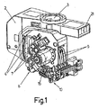
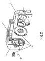
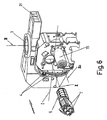
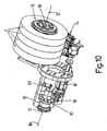
このヘッドは、従来、縦軸IIIの組立継手(3)に関する回転運動支持体(2)上に配置されていたが、ブロック(2.1)又は実際のヘッドは、前述の支持体(2)上の横軸Iの「小歯車−冠歯車」回転組立体(4)に組み込まれる(図1、図2及び図3参照)。 This head is conventionally arranged on the rotary motion support (2) with respect to the assembly joint (3) of the longitudinal axis III, but the block (2.1) or the actual head is the aforementioned support (2). It is incorporated into the "small gear-crown gear" rotating assembly (4) of the horizontal axis I (see FIGS. 1, 2 and 3).
本発明によれば、貼り付けられる炭素繊維のストリップを供給するための少なくとも2つの炭素繊維のストリップの供給リール(1)がヘッド内に配置される。 According to the invention, at least two carbon fiber strip supply reels (1) for supplying the carbon fiber strip to be applied are arranged in the head.
添付図面に示された非限定的な実際の実施形態によれば、ヘッドは、図10のとおり、4つのリール(1)を有し、各リールには、75mmの幅寸法を有する炭素繊維のストリップが巻かれる。従って、ヘッドが4つの炭素繊維のストリップを同時に貼り付ける場合には幅300mmに貼ることができ、それにより生産性が最大になる。それに対して75mm幅の1つのリール(1)だけを使用すると、しわを作ることなく極めて小さい半径を描くことができる。従って、描く半径の湾曲に応じて1個、2個、3個又は4個のリール(1)が使用される。ヘッドが、あまり複雑でない表面を覆うために使用される場合は、例えば、300mm幅のサイズを覆う2つの150mmのリール(1)を使用することもでき、或いはほぼ平らな部品のための大きな半径の湾曲を生じることができる単一の300mm幅のリール(1)を使用することもできる。 According to a non-limiting practical embodiment shown in the accompanying drawings, the head has four reels (1), as shown in FIG. 10, each reel of carbon fiber having a width dimension of 75 mm. A strip is wound. Therefore, if the head is to apply four carbon fiber strips simultaneously, it can be applied to a width of 300 mm, thereby maximizing productivity. On the other hand, if only one reel (1) with a width of 75 mm is used, a very small radius can be drawn without creating wrinkles. Accordingly, one, two, three, or four reels (1) are used according to the curvature of the drawn radius. If the head is used to cover less complex surfaces, for example, two 150 mm reels (1) covering a 300 mm wide size can be used, or a large radius for a nearly flat part It is also possible to use a single 300 mm wide reel (1) capable of producing a curvature of.
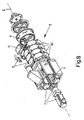
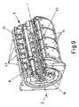
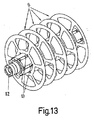
リール(1)は、シャフト(16)(図9参照)に取り付けられた個別の連続したリング(5.1)の組み立てによって形成された主ローラ(5)に取り付けられ、その論理上の縦軸IIは、横軸Iと垂直である。 The reel (1) is attached to the main roller (5) formed by the assembly of individual continuous rings (5.1) attached to the shaft (16) (see FIG. 9) and its logical longitudinal axis. II is perpendicular to the horizontal axis I.
図6、図8及び図9のとおり、リング(5.1)は、コンピュータ・プログラムによって制御される対応する個別のモータ(7)に対して、それぞれの回転作動トランスミッション(6)によって連結される。 As shown in FIGS. 6, 8 and 9, the ring (5.1) is connected by a respective rotationally actuated transmission (6) to a corresponding individual motor (7) controlled by a computer program. .
主ローラ(5)の前記部分(5.1)は、連続した部分(5.1)の側方対面間に配置された玉軸受(23)によって互いに分離され、連続した部分(5.1)のそれぞれの独立した回転が可能である(図9及び図9A参照)。 Said part (5.1) of the main roller (5) is separated from each other by a ball bearing (23) arranged between the side-to-face surfaces of the continuous part (5.1), and the continuous part (5.1) Can be rotated independently (see FIGS. 9 and 9A).
それぞれの部分(5.1)の前記回転は、図9Aのとおり、対応する部分(5.1)の内側の冠歯車(25)と噛み合わされた小歯車(24)を作動させるそれぞれの独立したモータ(7)によって制御され、その結果、本発明と同じ出願人の特許第P200200524号に記載されているように、この組立体によって、各部分(5.1)の個別の制御された回転作動が確保される。 Said rotation of each part (5.1), as shown in FIG. 9A, activates each independent gear (24) engaged with a crown gear (25) inside the corresponding part (5.1). Controlled by the motor (7), so that this assembly allows the individual controlled rotational actuation of each part (5.1) as described in the same applicant's patent P2002005524 as the present invention. Is secured.
これにより、リール(1)は、互いに異なる速度で回転することができ、その結果、例えば、湾曲部分に達したときに、例えば、湾曲の外側にあるストリップに対応するリール(1)が、その隣にあるリールよりも多く「回る」などし、湾曲から出るときは全てのリールが同じ速さで巻かれていない。 This allows the reels (1) to rotate at different speeds so that, for example, when reaching the curved part, for example, the reel (1) corresponding to the strip outside the curve is When you get out of a curve, such as "turning" more than the next reel, not all reels are wound at the same speed.
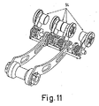
貼り付け用に設計された炭素繊維のストリップは、リール(1)に巻かれるときに前記ストリップが固着するのを防ぐ付随する従来の保護紙を備え、その結果、前記ストリップが被形成面に貼り付けられるとき、保護紙は、同じヘッド内でその目的のために配置された巻き取りスプール(8)内に収集される(図11参照)。 The carbon fiber strip designed for application is provided with an associated conventional protective paper that prevents the strip from sticking when wound on the reel (1), so that the strip is applied to the surface to be formed. When applied, the protective paper is collected in a take-up spool (8) arranged for that purpose in the same head (see FIG. 11).
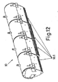
炭素繊維のストリップは、ガイド(9)によって主ローラ(5)上に取り付けられた供給リール(1)から送り出され(図1参照)、ガイド(9)は、図12のとおり、各ストリップを押し付けるための個別の加圧部分(10.1)によって形成された複数のヒール(10)が配置された貼り付け領域に達するまでストリップを離したままにし、その結果、各ストリップは、圧力によるストリップ貼り付け手段で被形成面に貼り付けられるか、又は貼り付けられない。 The carbon fiber strips are fed by a guide (9) from a supply reel (1) mounted on a main roller (5) (see FIG. 1), and the guide (9) presses each strip as shown in FIG. The strips are kept apart until they reach the application area where the plurality of heels (10) formed by the individual pressure parts (10.1) for placement are located, so that each strip is stripped by pressure Affixing means may or may not be affixed to the surface to be formed.
換言すると、被形成面に炭素繊維のストリップを貼り付ける際、ヒール(10)の対応する部分(10.1)によって初めに前記面に押し当てられることでストリップは被形成面に貼り付けられ、それに対して、ヒール(10)の各部分(10.1)によって押し付けられないストリップは、被形成面に貼り付けられることなく通過する。従って、ヘッドの動作制御プログラミングによって操作を選択し、貼り付け材料で覆わなければならない部分にのみ形成ストリップを貼り付けることによって、どのようなタイプの表面でも形成することができる。 In other words, when a carbon fiber strip is affixed to the forming surface, the strip is affixed to the forming surface by first being pressed against the surface by the corresponding part (10.1) of the heel (10), On the other hand, the strip that is not pressed by the respective parts (10.1) of the heel (10) passes through without being attached to the surface to be formed. Thus, any type of surface can be formed by selecting an operation by head motion control programming and applying the forming strip only to those portions that must be covered with the application material.
炭素繊維のストリップの供給リール(1)は、ストリップを送るためのガイド(9)内に配置された光センサと一緒に、長手方向の駆動ねじによる軸方向配置手段によって組み立てられ、これによりそれぞれのガイド(9)に対応してストリップの供給リール(1)を整列させる自動的な調整を実行することが可能である。 The carbon fiber strip supply reel (1) is assembled by means of an axial positioning means by means of a longitudinal drive screw, together with an optical sensor arranged in a guide (9) for feeding the strip, whereby It is possible to perform an automatic adjustment to align the supply reel (1) of the strip in response to the guide (9).
更に、主ローラ(5)を構成する各部分(5.1)は、その外面(図8〜図9A参照)に、空気圧システムによって半径方向に動くことができる板(11)を備え、前記板の手段によって前記部分(5.1)の直径方向への拡張部がリール(1)を固定するために作成される。そして、貼り付けのために供給されるストリップの作動は、対応するモータ(7)により部分(5.1)に供給される回転伝達によって操作される。 Furthermore, each part (5.1) constituting the main roller (5) is provided with a plate (11) on its outer surface (see FIGS. 8 to 9A) that can be moved in the radial direction by a pneumatic system. The diametrical extension of the part (5.1) is made by the means described above to fix the reel (1). Then, the operation of the strip supplied for pasting is operated by the rotation transmission supplied to the part (5.1) by the corresponding motor (7).
部分(5.1)の直径方向への拡張部の板(11)の半径方向の動きは、以下のように行われる(図9A参照)。 The radial movement of the extension plate (11) in the diametrical direction of the part (5.1) is performed as follows (see FIG. 9A).
固定ピストン(26)と軸方向可動ジャケット(27)の間にある空気チャンバ内の圧力が高くなると、前記ジャケット(27)は、対応する部分(5.1)の回転軸方向に動かされ、その結果、前述のジャケット(27)及び部分(5.1)と回転可能に一体となった斜面付きリング(29)との間にあるアンギュラ・コンタクト四点軸受(28)が、ジャケット(27)の長手方向の動きを前記斜面付きリング(29)に伝達すると同時にジャケット(27)が回転しないようにし、それに対して斜面付きリング(29)は、ピン又はスタッド(30)によって取り付けられた部分(5.1)と共に回転する。 When the pressure in the air chamber between the fixed piston (26) and the axially movable jacket (27) increases, the jacket (27) is moved in the direction of the axis of rotation of the corresponding part (5.1), As a result, the angular contact four-point bearing (28) between the previously described jacket (27) and the part (5.1) and the beveled ring (29) which is rotatably integrated with the jacket (27) The longitudinal movement is transmitted to the beveled ring (29) and at the same time the jacket (27) is prevented from rotating, whereas the beveled ring (29) is part (5) attached by a pin or stud (30). .1) rotate with.
斜面付きリング(29)の斜面上に、半径方向に配置されたボールを端部に備えた部品(31)が支持され、その結果、部品(31)の端部が、斜面付きリング(29)の斜面上を摺動し、前記部品(31)がそれに接して配置された板(11)に押し付けられるので、ジャケット(27)の空気圧による軸方向の動きによって引き起こされる斜面付きリング(29)の長手方向の動きによって、部品(31)が半径方向に動く。 On the slope of the beveled ring (29), a part (31) provided with balls arranged in the radial direction at the end is supported, so that the end of the part (31) is supported by the beveled ring (29). Since the part (31) is pressed against the plate (11) disposed in contact with the part (31), the ring (29) of the beveled ring (29) caused by the axial movement by the air pressure of the jacket (27) The longitudinal movement causes the part (31) to move radially.
部分(5.1)の外面には軸方向の溝がつけられ、その溝によって前記部分(5.1)上にリール(1)が完全に固定され、相対的な回転摺動が防止されてリール(1)の最適な制御が確保される。 The outer surface of the part (5.1) is axially grooved so that the reel (1) is completely fixed on the part (5.1) and prevents relative rotational sliding. Optimal control of the reel (1) is ensured.
更に、炭素繊維のストリップの保護紙を巻き取るための巻き取りスプール(8)が、図11のとおりシャフト(12)上に取り付けられ、空気圧システムによって作動されるくさび(13)方式によってロックされる。 Further, a take-up spool (8) for taking up the protective paper of the carbon fiber strip is mounted on the shaft (12) as shown in FIG. 11 and locked by a wedge (13) system actuated by a pneumatic system. .
主ローラ(5)に取り付けられた対応する供給リール(1)から出る炭素繊維のストリップに関し、炭素繊維のストリップは個々に、図11に示す配置されたセンサ(14)を通り、その結果、各ストリップの出口速度が前記センサ(14)によって制御され、対応するモータ(7)によるリール(1)への回転伝達の作動は、常に必要なストリップを貼り付ける速度に各ストリップの供給を合わせるためにその速度に従って調整され、貼り付けを不十分にする緊張や引っ張りが起こるのを防ぐ。 With respect to the carbon fiber strips coming out of the corresponding supply reel (1) attached to the main roller (5), the carbon fiber strips individually pass through the arranged sensors (14) shown in FIG. The exit speed of the strip is controlled by the sensor (14) and the operation of the rotation transmission to the reel (1) by the corresponding motor (7) is always in order to adapt the supply of each strip to the speed at which the required strip is applied. Adjusted according to its speed, it prevents the tension and tension that makes the sticking insufficient.
更に、前述のセンサ(14)は、揺動配置で配置され、それにより前記リール(1)上の対応するストリップが消費されたときのリール(1)の慣性の変化を補正することが可能であり、これにより供給工程中のストリップの張力が一定で、貼り付けが均一になる。 Furthermore, the aforementioned sensor (14) is arranged in an oscillating arrangement, so that it is possible to compensate for changes in the inertia of the reel (1) when the corresponding strip on the reel (1) is consumed. With this, the tension of the strip during the feeding process is constant and the application is uniform.
本発明の装置による炭素繊維のストリップを貼り付けるための貼り付け方法は、前述のヘッドによって、最少のパス回数で貼り付け面を覆うことを可能にするストリップの幅と同等の全幅を有する2つ以上のストリップを使用して行うことができるが、それにより各ストリップを供給する速度を制御することによって、必要なまっすぐな経路及び湾曲した経路をたどるストリップを貼り付けることができる。まっすぐな貼り付け領域では、すべてのストリップが同じ速度で供給されるが、湾曲した貼り付けでは、湾曲の外側部分に貼り付けるストリップは、湾曲の内側部分に貼り付けられるストリップより早い速度で供給される。これにより、貼り付けは、外側部分のストリップが延びることなく、且つ内側部分でしわが寄ることなしに、貼り付けの幅全体が均一になる。示したように、所定の時に、1つのリール(1)のストリップだけを貼り付け、残りのリールのストリップを貼り付けなくてもよく、或いは全ての可能な論理的変形が可能であり、本明細書に示した実際の実施形態により、4つの独立したリール(1)を使用できること、又は必要であれば更に多くのリール(1)を備えることが考慮される。 Two methods of attaching carbon fiber strips with the apparatus of the present invention have two full widths equal to the width of the strip that allows the head to cover the application surface with a minimum number of passes. The above strips can be used, but by controlling the rate at which each strip is fed, the strips following the required straight and curved paths can be applied. In a straight pasting area, all strips are fed at the same rate, but in curved pasting, the strip that is pasted on the outer part of the curve is fed at a faster rate than the strip that is pasted on the inner part of the curve. The As a result, the entire width of the application is uniform without the strip of the outer part extending and without wrinkling at the inner part. As shown, at a given time, only one reel (1) strip may be applied and the remaining reel strips may not be applied, or all possible logical variations are possible. According to the actual embodiment shown in the document, it is considered that four independent reels (1) can be used, or that more reels (1) are provided if necessary.
このような状態では、貼り付け工程は、リール(1)が空になったときに前記リール(1)が個別に交換され、リール(1)のうちの残りのリールは、工程で各リールが空になるまで使い続けられ、それらのリールは同じように個別に交換される。この方法では、炭素繊維のストリップが完全に活用されるが、リールが空になったときに各リール(1)を交換するために何度も工程を停止しなければならない。 In such a state, in the attaching process, when the reel (1) becomes empty, the reel (1) is individually replaced, and the remaining reels of the reel (1) They continue to be used until they are empty, and the reels are exchanged individually as well. This method makes full use of carbon fiber strips, but the process must be stopped many times to replace each reel (1) when the reels are empty.
同様に、リールのうちの1つが空になったときに全ての炭素繊維のストリップの供給リール(1)を交換する貼り付け方法にすることができ、それにより全てのリール(1)がそれぞれの取り換えの停止で交換され、従って全てのリールが完全に充填された状態から供給工程を再開するので、必要な停止の回数が減少する。しかしながら、この方法では、リール(1)が空にならずに交換されたときに、使い終わっていないリール(1)の残りが全て破棄されるので、材料の損失がある。 Similarly, it can be affixed to replace the supply reel (1) of all carbon fiber strips when one of the reels is empty, so that all reels (1) Since the supply process is restarted from the state where all reels are completely filled, and the number of necessary stops is reduced. However, in this method, when the reel (1) is replaced without being emptied, the remainder of the reel (1) that has not been used is completely discarded, and there is a loss of material.
本発明での特別なオプションによれば、炭素繊維のストリップの供給に関して、同じか又は異なる部品を形成するために連続貼り付け用のプログラムと組み合わされた管理ソフトウェア・プログラムが適用され、その結果、前記ソフトウェアは、異なる使用で実行しなければならないストリップを貼り付けるための行程距離を計算し、それらを実行する順序を決定する。それにより、ある使用におけるいくつかの貼り付け用ストリップの消費の増大が、他の使用における他のストリップの消費の増大で相殺され、それにより貼り付け用ストリップを保持する全てのリール(1)が同時に空になる。この方法では、全てのリール(1)は同じ取り換えの停止で交換され、無駄な処分がないので、ストリップの炭素繊維材料が完全に活用される。 According to a special option in the present invention, a management software program combined with a program for continuous application is applied to form the same or different parts with respect to the supply of carbon fiber strips, so that The software calculates the travel distance for applying the strips that must be performed in different uses and determines the order in which they are performed. Thereby, an increase in consumption of some sticking strips in one use is offset by an increase in consumption of other strips in another use, so that all reels (1) holding the sticking strips are At the same time it becomes empty. In this way, all the reels (1) are replaced with the same replacement stop and there is no wasteful disposal, so that the strip carbon fiber material is fully utilized.
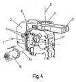
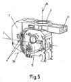
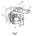
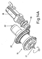
本発明の別の特徴によれば、ヘッドに、ブロック(2.1)の側方に向けられた主ローラ(5)の軸IIと平行な軸IIaで配置された超音波切断ユニット(15)が組み込まれる(図4、図5及び図6参照)。 According to another characteristic of the invention, an ultrasonic cutting unit (15) arranged on the head with an axis IIa parallel to the axis II of the main roller (5) directed to the side of the block (2.1 ). Is incorporated (see FIGS. 4, 5 and 6).
この構成では、図14に示したように、横軸Iにおける組立体(4)に接するブロック(2.1)を、炭素繊維のストリップ貼り付け位置に対して90°回転させることによって、切断ユニット(15)は、貼り付け面の形成で使用される炭素繊維のストリップの残りの部分を切断する作動位置になる。 In this configuration, as shown in FIG. 14, the block (2.1) in contact with the assembly (4) on the horizontal axis I is rotated by 90 ° with respect to the carbon fiber strip application position, thereby cutting the cutting unit. (15) is the operating position for cutting the remaining portion of the carbon fiber strip used in forming the affixing surface.
これにより、ストリップを貼り付ける同一ヘッドが、図1に示した貼り付け位置と図14に示した切断との間で、ヘッドのブロック(2.1)を軸Iのまわりに単純に90°回転させることによって前記ストリップの残りの部分を切断するので、炭素繊維のストリップが形成される部品を製造する工程の所要時間が短縮される。 This allows the same head to which the strip is to be attached to simply rotate the head block (2.1) about axis I by 90 ° between the attachment position shown in FIG. 1 and the cutting shown in FIG. Cutting the remaining portion of the strip, thereby reducing the time required for the process of manufacturing the part from which the carbon fiber strip is formed.
図14Aに示すように、切断ユニット(15)は、炭素繊維材料を切断することができるように、小歯車(19)及び冠歯車(20)を介してサーボ・モータ(18)によって作動されるサーボ制御された作動手段によるブレード(17)の回転(CU)を有する。 As shown in FIG. 14A, the cutting unit (15) is actuated by a servo motor (18) via a small gear (19) and a crown gear (20) so that the carbon fiber material can be cut. With rotation (CU) of the blade (17) by servo-controlled actuation means.
ブレード(17)は、10分の数ミリメートルの振幅の超音波周波数によって軸方向に加振され、それにより残っている付着した未硬化の材料を炭素繊維のストリップから切断することができる。ブレード(17)の前記周波数は、ヘッドの支持体(2)に取り付けられた共振器(21)によって生成され、収集器(22)に伝達され、それによりブレード(17)が回転(CU)で回転作動されたときでも、ブレード(17)を加振できる。 The blade (17) is vibrated axially by an ultrasonic frequency with an amplitude of a few tenths of a millimeter so that the remaining deposited uncured material can be cut from the carbon fiber strip. The frequency of the blade (17) is generated by the resonator (21) attached to the support (2) of the head and transmitted to the collector (22), whereby the blade (17) is rotated (CU). The blade (17) can be vibrated even when rotated.
1 供給リール
4 小歯車及び冠歯車
5 主ローラ
5.1 主ローラの部分
6 回転作動トランスミッション
7 モータ
8 スプール
9 ガイド
10 ヒール
11 板
12 シャフト
13 くさび
14 センサ
15 超音波切断ユニット
DESCRIPTION OF SYMBOLS 1 Supply reel 4 Small gear and
10
Claims (10)
前記ヘッドは、垂直軸での回転組立体として配置された型であり、前記ストリップの貼り付けを行うブロックが横軸(I)に配置され、供給リールから供給され且つ保護紙を備えた前記ストリップによって部品の表面を形成し、前記ストリップは、前記表面に対する圧力によって被形成面に貼り付けられ、前記保護紙は巻き取りスプールに巻き取られる前記ヘッドであって、
前記ヘッドは、少なくとも2つの前記供給リール(1)を備え、前記供給リール(1)は、前記ストリップを選択的に供給するためにそれぞれに前記ストリップを保持し、前記ストリップで前記ストリップの貼り付け幅を形成し、貼り付け用の前記ストリップの前記供給リール(1)は主ローラ(5)に取り付けられ、前記主ローラ(5)は、それぞれの回転伝達によって個々に作動される個別の部分(5.1)によって構成され、これにより前記供給リール(1)からの前記ストリップの個別の供給が可能であることを特徴とするヘッド。 In the head for attaching the carbon fiber strip,
The head is arranged mold as rotating assembly in the vertical axis, said strip block for attachment of said strips are arranged on the horizontal axis (I), with a and protective paper is fed from a supply reel Forming the surface of the part by means of the head, wherein the strip is affixed to the surface to be formed by pressure against the surface and the protective paper is wound on a take-up spool;
The head comprises at least two supply reels (1), the supply reel (1) holding the strip on each to selectively supply the strip, and attaching the strip with the strip The supply reel (1) of the strip for forming and sticking is attached to a main roller (5), the main roller (5) being individually actuated by a respective rotation transmission ( 5.1), characterized in that the strips can be supplied individually from the supply reel (1).
前記ストリップの複数の供給リール(1)が組み込まれたヘッドを用い、前記供給リール(1)によって被形成面での前記ストリップの貼り付け幅が形成され、前記供給リール(1)は、主ローラ(5)の複数の個別の部分(5.1)に配置され、前記部分(5.1)は、貼り付ける前記ストリップを回転するために個々に作動され、前記ストリップの前記供給リール(1)に関して、貼り付け面の各領域内において必要とされる貼り付けに従ってそれぞれの前記供給リールの前記ストリップの貼り付けを決定し、それぞれの前記供給リール(1)の速度の個別の制御が行程距離の差を補正し、湾曲した貼り付け領域内において、前記湾曲の外側部分の前記ストリップを内側部分の前記ストリップより早い速度で供給することを特徴とする炭素繊維のストリップを貼り付ける方法。 A method of applying a carbon fiber strip,
Using a head in which a plurality of supply reels (1) of the strip are incorporated, the supply reel (1) forms a width of the strip on the surface to be formed, and the supply reel (1) is a main roller. Arranged in a plurality of individual parts (5.1) of (5), said parts (5.1) being individually actuated for rotating said strip to be applied, said supply reel (1) of said strip The application of the strip of each supply reel is determined according to the required application in each region of the application surface, and the individual control of the speed of each of the supply reels (1) is a process distance control. Charcoal, correcting the difference and supplying the strip of the outer part of the curve at a faster rate than the strip of the inner part in a curved pasting area How to paste a strip of fiber.
Applications Claiming Priority (3)
| Application Number | Priority Date | Filing Date | Title |
|---|---|---|---|
| ES200602154A ES2291131B1 (en) | 2006-08-08 | 2006-08-08 | APPLICATION HEAD OF CARBON FIBER TAPES AND APPLICATION METHOD. |
| ESP200602154 | 2006-08-08 | ||
| PCT/ES2007/000382 WO2008020094A1 (en) | 2006-08-08 | 2007-06-28 | Head for application of carbon-fibre strips and application method |
Publications (3)
| Publication Number | Publication Date |
|---|---|
| JP2010500191A JP2010500191A (en) | 2010-01-07 |
| JP2010500191A5 JP2010500191A5 (en) | 2011-11-24 |
| JP5517618B2 true JP5517618B2 (en) | 2014-06-11 |
Family
ID=39031179
Family Applications (1)
| Application Number | Title | Priority Date | Filing Date |
|---|---|---|---|
| JP2009523309A Expired - Fee Related JP5517618B2 (en) | 2006-08-08 | 2007-06-28 | Head for affixing carbon fiber strip and affixing method |
Country Status (6)
| Country | Link |
|---|---|
| US (1) | US8202385B2 (en) |
| EP (1) | EP2055463A4 (en) |
| JP (1) | JP5517618B2 (en) |
| CN (1) | CN101500786B (en) |
| ES (1) | ES2291131B1 (en) |
| WO (1) | WO2008020094A1 (en) |
Cited By (1)
| Publication number | Priority date | Publication date | Assignee | Title |
|---|---|---|---|---|
| KR102498897B1 (en) * | 2021-11-24 | 2023-02-10 | 강영길 | Filament handling unit for winding machine |
Families Citing this family (11)
| Publication number | Priority date | Publication date | Assignee | Title |
|---|---|---|---|---|
| ES2331825B1 (en) * | 2007-10-08 | 2010-07-22 | Manuel Torres Martinez | PERFECTION IN FIBER RIBBON APPLICATION HEADS. |
| US8557074B2 (en) * | 2008-02-27 | 2013-10-15 | The Boeing Company | Reduced complexity automatic fiber placement apparatus and method |
| FR2981000B1 (en) * | 2011-10-06 | 2013-11-29 | Snecma | DEVICE FOR MANUFACTURING A PIECE OF COMPOSITE MATERIAL |
| US20140255646A1 (en) * | 2013-03-08 | 2014-09-11 | The Boeing Company | Forming Composite Features Using Steered Discontinuous Fiber Pre-Preg |
| JP6185350B2 (en) * | 2013-09-24 | 2017-08-23 | 東邦テナックス株式会社 | Prepreg automatic laminating apparatus, prepreg laminated body manufacturing method, and fiber reinforced composite material manufacturing apparatus |
| US10625477B2 (en) | 2014-09-25 | 2020-04-21 | Toray Industries, Inc. | Reinforcing fiber sheet manufacturing apparatus |
| FR3059932B1 (en) * | 2016-12-09 | 2021-01-29 | Inst De Rech Tech Jules Verne | CASSETTE, DEPOSIT HEAD INCLUDING SUCH A CASSETTE, INSTALLATION, DRAPING PROCESS, CHARGING PROCEDURE AND PREPARATION PROCESS |
| FR3063673B1 (en) * | 2017-03-13 | 2020-06-12 | Institut De Recherche Technologique Jules Verne | MOBILE PLATFORM FOR PARALLEL CABLE ROBOT, PARALLEL CABLE ROBOT, INSTALLATION AND METHOD OF DREDGING USING SUCH ROBOT |
| KR101980145B1 (en) * | 2017-08-31 | 2019-05-20 | 고대운 | Carbon fiber supplying device |
| CN110723597A (en) * | 2019-10-22 | 2020-01-24 | 苏州市职业大学 | A continuous wrapping device |
| FR3131706B1 (en) * | 2022-01-12 | 2024-08-23 | Safran | Application head for automatic fiber placement |
Family Cites Families (21)
| Publication number | Priority date | Publication date | Assignee | Title |
|---|---|---|---|---|
| US2122292A (en) * | 1937-09-21 | 1938-06-28 | James Joseph Lannon | Carrier for braiding machines |
| US2436067A (en) * | 1945-07-26 | 1948-02-17 | Nye Wait Company Inc | Tension regulator and equalizer for pile fabric looms |
| US3122872A (en) * | 1962-09-24 | 1964-03-03 | Gen Motors Corp | Flexible cable winding machine |
| US3810805A (en) * | 1972-04-14 | 1974-05-14 | Goldsworthy Eng Inc | Geodesic path length compensator for composite-tape placement head |
| US4292108A (en) * | 1979-12-10 | 1981-09-29 | General Dynamics Corporation | Composite tape laying apparatus including means for plural longitudinal and transverse cuts |
| US4461669A (en) * | 1983-09-30 | 1984-07-24 | The Boeing Company | Pivotal mount for laminating head |
| JPS61290038A (en) * | 1985-06-19 | 1986-12-20 | Agency Of Ind Science & Technol | Automatic sticking method for for tape and its device |
| US4699683A (en) * | 1986-02-07 | 1987-10-13 | The Boeing Company | Multiroving fiber laminator |
| JPS63229297A (en) * | 1987-03-19 | 1988-09-26 | 工業技術院長 | Automatic cutter for frp tape |
| US4943338A (en) * | 1988-09-26 | 1990-07-24 | Cincinnati Milacron Inc. | Multi-tow fiber placement machine with full band width clamp, cut, and restart capability |
| US5110395A (en) * | 1989-12-04 | 1992-05-05 | Cincinnati Milacron Inc. | Fiber placement head |
| JPH0639133B2 (en) * | 1990-06-27 | 1994-05-25 | 川崎重工業株式会社 | Roving material automatic laminating equipment |
| JPH0483714U (en) * | 1990-11-30 | 1992-07-21 | ||
| ES2114413B1 (en) * | 1994-10-07 | 1999-02-16 | Torres Martinez M | HEAD FOR THE APPLICATION OF COMPOSITE BANDS. |
| AU1360199A (en) * | 1997-11-05 | 1999-05-24 | Sikorsky Aircraft Corporation | Feed control system for fiber placement machines |
| US6544367B1 (en) * | 1999-02-01 | 2003-04-08 | Alliant Techsystems Inc. | Overwrap tape end-effector for fiber placement/winding machines |
| JP2002137241A (en) * | 2000-11-06 | 2002-05-14 | Mitsubishi Heavy Ind Ltd | Automatic laminate molding device and molding method |
| US6799081B1 (en) * | 2000-11-15 | 2004-09-28 | Mcdonnell Douglas Corporation | Fiber placement and fiber steering systems and corresponding software for composite structures |
| ES2212878B1 (en) * | 2002-03-05 | 2005-07-16 | Manuel Torres Martinez | MULTI-APPLICATOR HEAD OF FIBER STRIPS. |
| JP3632177B2 (en) * | 2002-11-29 | 2005-03-23 | 川崎重工業株式会社 | Pre-preg width changing automatic lamination method and apparatus |
| ES2246713B1 (en) * | 2004-07-27 | 2006-12-01 | Manuel Torres Martinez | "IMPROVEMENTS IN A MULTI-APPLICATOR HEAD OF FIBER STRIPS". |
-
2006
- 2006-08-08 ES ES200602154A patent/ES2291131B1/en not_active Expired - Fee Related
-
2007
- 2007-06-28 CN CN2007800293161A patent/CN101500786B/en not_active Expired - Fee Related
- 2007-06-28 JP JP2009523309A patent/JP5517618B2/en not_active Expired - Fee Related
- 2007-06-28 WO PCT/ES2007/000382 patent/WO2008020094A1/en not_active Ceased
- 2007-06-28 US US12/309,972 patent/US8202385B2/en not_active Expired - Fee Related
- 2007-06-28 EP EP07788630.7A patent/EP2055463A4/en not_active Withdrawn
Cited By (1)
| Publication number | Priority date | Publication date | Assignee | Title |
|---|---|---|---|---|
| KR102498897B1 (en) * | 2021-11-24 | 2023-02-10 | 강영길 | Filament handling unit for winding machine |
Also Published As
| Publication number | Publication date |
|---|---|
| JP2010500191A (en) | 2010-01-07 |
| US8202385B2 (en) | 2012-06-19 |
| WO2008020094A1 (en) | 2008-02-21 |
| EP2055463A1 (en) | 2009-05-06 |
| CN101500786A (en) | 2009-08-05 |
| ES2291131B1 (en) | 2008-12-01 |
| EP2055463A4 (en) | 2014-02-19 |
| US20090266485A1 (en) | 2009-10-29 |
| CN101500786B (en) | 2012-11-28 |
| ES2291131A1 (en) | 2008-02-16 |
Similar Documents
| Publication | Publication Date | Title |
|---|---|---|
| JP5517618B2 (en) | Head for affixing carbon fiber strip and affixing method | |
| JP5785259B2 (en) | Head for sticking fiber strip | |
| US4557790A (en) | Tape laminator | |
| US7785433B2 (en) | End effector and methods for constructing composite members | |
| US7048024B2 (en) | Unidirectional, multi-head fiber placement | |
| EP3278964B1 (en) | Feed device for reinforcing fiber material and method for cutting reinforcing fiber material by using the feed device | |
| US7083698B2 (en) | Automated composite lay-up to an internal fuselage mandrel | |
| JP5550851B2 (en) | Multi-head automated composite laminating machine for the production of large barrel components | |
| US8156988B2 (en) | Fiber strip multiapplicator head and method for applying the fiber strips | |
| US6026883A (en) | Self-contained apparatus for fiber element placement | |
| JP2010500191A5 (en) | ||
| WO2017150186A1 (en) | Three-dimensional printing apparatus and three-dimensional printing method | |
| EP4342662A1 (en) | Roller unit for feeding tapes, fiber placement apparatus and method of molding composite material | |
| JP2005528257A (en) | Apparatus for manufacturing tire reinforcing structure having direction change mechanism of narrow band | |
| US7399374B2 (en) | System for producing a reinforcing structure for a tire with volumetric control | |
| JPS62144927A (en) | Automatic application process of frp tape and its device | |
| EP4342661A1 (en) | Roller unit for feeding tapes, fiber placement apparatus and method of molding composite material | |
| JP2014139356A (en) | Fuzz-forming apparatus | |
| CN222080325U (en) | Coating composite equipment | |
| US20250205979A1 (en) | Fiber width adjustment device and method of molding composite material | |
| EP4349573A1 (en) | Method of producing preform and method of molding composite material | |
| WO2025183073A1 (en) | Winding device and winding method for reinforced fiber bundle | |
| CN121042730A (en) | A double-layer film roll ultraviolet light splitting and cutting device | |
| JPH08141991A (en) | Trimming device |
Legal Events
| Date | Code | Title | Description |
|---|---|---|---|
| A621 | Written request for application examination |
Free format text: JAPANESE INTERMEDIATE CODE: A621 Effective date: 20100303 |
|
| A521 | Request for written amendment filed |
Free format text: JAPANESE INTERMEDIATE CODE: A523 Effective date: 20111004 |
|
| A977 | Report on retrieval |
Free format text: JAPANESE INTERMEDIATE CODE: A971007 Effective date: 20120224 |
|
| A131 | Notification of reasons for refusal |
Free format text: JAPANESE INTERMEDIATE CODE: A131 Effective date: 20120305 |
|
| A521 | Request for written amendment filed |
Free format text: JAPANESE INTERMEDIATE CODE: A523 Effective date: 20120605 |
|
| A131 | Notification of reasons for refusal |
Free format text: JAPANESE INTERMEDIATE CODE: A131 Effective date: 20130318 |
|
| A521 | Request for written amendment filed |
Free format text: JAPANESE INTERMEDIATE CODE: A523 Effective date: 20130611 |
|
| TRDD | Decision of grant or rejection written | ||
| A01 | Written decision to grant a patent or to grant a registration (utility model) |
Free format text: JAPANESE INTERMEDIATE CODE: A01 Effective date: 20140310 |
|
| A61 | First payment of annual fees (during grant procedure) |
Free format text: JAPANESE INTERMEDIATE CODE: A61 Effective date: 20140401 |
|
| R150 | Certificate of patent or registration of utility model |
Ref document number: 5517618 Country of ref document: JP Free format text: JAPANESE INTERMEDIATE CODE: R150 |
|
| R250 | Receipt of annual fees |
Free format text: JAPANESE INTERMEDIATE CODE: R250 |
|
| R250 | Receipt of annual fees |
Free format text: JAPANESE INTERMEDIATE CODE: R250 |
|
| LAPS | Cancellation because of no payment of annual fees |