JP5515351B2 - Image output apparatus, control method, and control program - Google Patents
Image output apparatus, control method, and control program Download PDFInfo
- Publication number
- JP5515351B2 JP5515351B2 JP2009072108A JP2009072108A JP5515351B2 JP 5515351 B2 JP5515351 B2 JP 5515351B2 JP 2009072108 A JP2009072108 A JP 2009072108A JP 2009072108 A JP2009072108 A JP 2009072108A JP 5515351 B2 JP5515351 B2 JP 5515351B2
- Authority
- JP
- Japan
- Prior art keywords
- display
- virtual
- screen
- unit
- virtual screen
- Prior art date
- Legal status (The legal status is an assumption and is not a legal conclusion. Google has not performed a legal analysis and makes no representation as to the accuracy of the status listed.)
- Active
Links
Images


Classifications
-
- G—PHYSICS
- G06—COMPUTING; CALCULATING OR COUNTING
- G06F—ELECTRIC DIGITAL DATA PROCESSING
- G06F3/00—Input arrangements for transferring data to be processed into a form capable of being handled by the computer; Output arrangements for transferring data from processing unit to output unit, e.g. interface arrangements
- G06F3/14—Digital output to display device ; Cooperation and interconnection of the display device with other functional units
- G06F3/1423—Digital output to display device ; Cooperation and interconnection of the display device with other functional units controlling a plurality of local displays, e.g. CRT and flat panel display
-
- H—ELECTRICITY
- H04—ELECTRIC COMMUNICATION TECHNIQUE
- H04N—PICTORIAL COMMUNICATION, e.g. TELEVISION
- H04N9/00—Details of colour television systems
- H04N9/12—Picture reproducers
- H04N9/31—Projection devices for colour picture display, e.g. using electronic spatial light modulators [ESLM]
- H04N9/3141—Constructional details thereof
- H04N9/3147—Multi-projection systems
-
- H—ELECTRICITY
- H04—ELECTRIC COMMUNICATION TECHNIQUE
- H04N—PICTORIAL COMMUNICATION, e.g. TELEVISION
- H04N9/00—Details of colour television systems
- H04N9/12—Picture reproducers
- H04N9/31—Projection devices for colour picture display, e.g. using electronic spatial light modulators [ESLM]
- H04N9/3179—Video signal processing therefor
-
- G—PHYSICS
- G09—EDUCATION; CRYPTOGRAPHY; DISPLAY; ADVERTISING; SEALS
- G09G—ARRANGEMENTS OR CIRCUITS FOR CONTROL OF INDICATING DEVICES USING STATIC MEANS TO PRESENT VARIABLE INFORMATION
- G09G2320/00—Control of display operating conditions
- G09G2320/06—Adjustment of display parameters
- G09G2320/0606—Manual adjustment
-
- G—PHYSICS
- G09—EDUCATION; CRYPTOGRAPHY; DISPLAY; ADVERTISING; SEALS
- G09G—ARRANGEMENTS OR CIRCUITS FOR CONTROL OF INDICATING DEVICES USING STATIC MEANS TO PRESENT VARIABLE INFORMATION
- G09G2370/00—Aspects of data communication
- G09G2370/04—Exchange of auxiliary data, i.e. other than image data, between monitor and graphics controller
- G09G2370/042—Exchange of auxiliary data, i.e. other than image data, between monitor and graphics controller for monitor identification
Description
本発明は、画像出力装置、制御方法、及び制御プログラムに関する。 The present invention relates to an image output apparatus, a control method, and a control program.
従来、入力される画像情報に基づく画面を表示する表示装置と、画像情報に基づく画面を表示する表示部を有し、表示装置に対して画像情報を出力する画像出力装置とを備える画像表示システムが知られている(例えば、特許文献1参照)。
特許文献1に記載の画像表示システムは、4つのプロジェクター(表示装置)と、ディスプレイ(表示部)を備えるコンピューター(画像出力装置)とを備え、コンピューターは、複数の仮想ディスプレイを生成し、生成した各仮想ディスプレイに係る画像情報を各プロジェクターに対して出力している。そして、プロジェクターは、入力される画像情報に基づく画面を表示している。
2. Description of the Related Art Conventionally, an image display system includes a display device that displays a screen based on input image information, and an image output device that has a display unit that displays a screen based on image information and outputs image information to the display device. Is known (see, for example, Patent Document 1).
The image display system described in
しかしながら、特許文献1に記載のコンピューターでは、各仮想ディスプレイ、及び各プロジェクターは予め関連付けられているので、画像表示システムの使用者は、各仮想ディスプレイに係る画像情報を出力するプロジェクターを選択することができないという問題がある。
また、各プロジェクターは、各仮想ディスプレイが関連付けられた後でなければ画面を表示することができないので、画像表示システムの使用者は、所望のプロジェクターに対して所望の画面を表示させるのに手間がかかるという問題がある。
However, in the computer described in
Further, since each projector can display the screen only after each virtual display is associated, the user of the image display system has a trouble in displaying the desired screen on the desired projector. There is a problem that it takes.
本発明の目的は、所望の表示装置に対して所望の画面を容易に表示させることができる画像出力装置、制御方法、及び制御プログラムを提供することにある。 An object of the present invention is to provide an image output device, a control method, and a control program capable of easily displaying a desired screen on a desired display device.
本発明の画像出力装置は、画像情報を出力する画像出力装置であって、表示部と、それぞれ仮想的な画面である複数の仮想画面に係る画像情報を生成する画面生成部と、当該画像出力装置に接続された表示装置を検出する検出部と、入力操作が行われる操作部と、前記操作部に対して、前記検出部にて検出された前記表示装置と、前記複数の仮想画面のいずれかとを関連付ける入力操作が行われると、当該入力操作に基づいて、前記検出部にて検出された前記表示装置と、前記複数の仮想画面のいずれかとを関連付けて、関連付けがされた前記仮想画面に係る画像情報を、関連付けがされた前記表示装置に出力可能とする関連付け部と、前記画面生成部にて生成された前記複数の仮想画面を前記表示部に表示させる表示制御部と、を備え、前記表示制御部は、前記複数の仮想画面のうちいずれか1つの仮想画面を前記表示部における表示領域の全体に表示させるとともに、前記複数の仮想画面のうち前記表示領域の全体に表示されている仮想画面とは異なる少なくとも1つの仮想画面を前記表示領域の一部に縮小して表示させることを特徴とする。 An image output apparatus of the present invention is an image output apparatus that outputs image information, and includes a display unit, a screen generation unit that generates image information relating to a plurality of virtual screens, each of which is a virtual screen, and the image output a detector for detecting the connected Viewing device apparatus, an operation section an input operation is performed with respect to the operation unit, the display device detected by the detecting unit, of the plurality of virtual screens If any preparative associated Ru input operation is performed, based on the input operation, and the display device detected by the detection unit, in association with and either said plurality of virtual screens, is the association An association unit capable of outputting image information related to the virtual screen to the associated display device, and a display control unit for displaying the plurality of virtual screens generated by the screen generation unit on the display unit And equipped with The display control unit causes any one virtual screen of the plurality of virtual screens to be displayed on the entire display region of the display unit, and the virtual displayed on the entire display region of the plurality of virtual screens. characterized Rukoto be displayed by reducing the at least one different virtual screen on a part of the display area and the screen.
このような構成によれば、画像出力装置は、検出部にて検出された表示装置、すなわち画像出力装置に接続された表示装置と、仮想画面とを関連付けるための入力操作が操作部に対して行われると、当該入力操作に基づいて、画像出力装置に接続された表示装置と、仮想画面とを関連付けて、当該仮想画面に係る画像情報を表示装置に出力可能とする関連付け部を備える。したがって、使用者は、操作部に対する入力操作を行うことで所望の表示装置に対して所望の画面を容易に表示させることができる。 According to such a configuration, images output device detected Viewing apparatus by the detector, i.e. a Viewing device connected to the image output apparatus, an input operation for associating the virtual screen operation When it made to the part, based on the input operation, and Viewing apparatus connected to the image output apparatus, in association with the virtual screen, and can output image information relating to the virtual screen on the display device An associating unit . Therefore, the user can easily display a desired screen on a desired display device by performing an input operation on the operation unit .
前記画面生成部は、複数の前記仮想画面に係る画像情報を生成し、当該画像出力装置は、画像情報に基づく画像を表示する表示部と、前記画面生成部にて生成された複数の前記仮想画面を前記表示部に表示させる表示制御部とを備えるので、当該画像出力装置の使用者は、表示部を見ることで各仮想画面がどのような画面であるかを確認することができる。 Multiple front Kiga plane generation unit generates image information related to a plurality of the virtual screen, the image output apparatus includes a display unit displaying an image based on image information, which is generated by the screen generating unit than the of the virtual screen Ru and a display control unit for displaying on the display unit, the user of the image output device confirms whether the virtual screen is what the screen by looking at the display unit be able to.
前記表示制御部は、複数の前記仮想画面のうち、いずれか1つの仮想画面を前記表示部における表示領域の全体に表示させるとともに、前記複数の仮想画面のうち前記表示領域の全体に表示されている仮想画面とは異なる少なくとも1つの仮想画面を前記表示領域の一部に縮小して表示させる。 Before Symbol display control unit among the plurality of the virtual screen, with displays of any one of the virtual screen to the entire display area of the display unit, it is displayed on the entire of the display region among the plurality of virtual screens and the virtual screen and Ru is reduced and displayed on a part of the prior Symbol table display region different at least one virtual screen.
このような構成によれば、表示部における表示領域の全体に1つの仮想画面を表示させることができるので、使用者の利便性を向上させることができる。 According to such a configuration, since one virtual screen can be displayed on the entire display area in the display unit, the convenience for the user can be improved.
本発明では、前記表示制御部は、前記表示領域の一部に縮小して表示される前記少なくとも1つの仮想画面のうち、前記表示装置との関連付けがされた仮想画面に係る画像情報の情報量を、当該表示装置に出力される画像情報の情報量と比較して低減させることが好ましい。
このような構成によれば、表示部に表示される各仮想画面に係る画像情報の情報量を、各表示装置に出力される画像情報の情報量と同じにする場合と比較して、画像表示装置にかかる負荷を低減させることができる。
In the present invention, the display control unit includes an information amount of image information related to a virtual screen associated with the display device among the at least one virtual screen displayed in a reduced size in a part of the display area. Is preferably compared with the amount of image information output to the display device.
According to such a configuration, the amount of image information related to each virtual screen displayed on the display unit is the same as the amount of image information output to each display device. The load applied to the apparatus can be reduced.
本発明では、前記表示制御部は、前記表示領域の一部に縮小して表示された前記仮想画面を、前記表示領域の全体に表示させる際に、前記縮小して表示されていた前記仮想画面を所定のパターン画像とすることが好ましい。 In the present invention, the display control unit is configured to display the virtual screen displayed in a reduced size when the virtual screen displayed in a reduced size in a part of the display region is displayed in the entire display region. The screen is preferably a predetermined pattern image.
ここで、使用者は、表示部における表示領域の全体に表示させた仮想画面については、表示部における表示領域の一部に縮小して表示させた各仮想画面を見ることなく、表示部における表示領域の全体を見ることで確認することができる。
したがって、本発明によれば、表示制御部は、表示部における表示領域の一部に縮小して表示させた各仮想画面のうち、表示部における表示領域の全体に表示させた仮想画面に応じた画像を所定のパターン画像(例えば、全画素を黒色とした画像)とすることで、画像表示装置にかかる負荷を低減させることができる。
Here, with respect to the virtual screen displayed on the entire display area in the display unit, the user can display the virtual screen displayed on the display unit without looking at each virtual screen displayed on a part of the display area on the display unit. This can be confirmed by looking at the entire area.
Therefore, according to the present invention, the display control unit responds to the virtual screen displayed in the entire display area in the display unit among the virtual screens displayed in a reduced manner in a part of the display area in the display unit . images predetermined pattern image (for example, all the pixels and the images black) with, it is possible to reduce the load on the image display device.
本発明では、前記操作部に対して、前記関連付け部にて前記表示装置と関連付けられた前記仮想画面を消去する入力操作が行われると、前記表示制御部は、当該入力操作に応じた前記仮想画面を前記表示領域から消去することが好ましい。 In the present invention, when an input operation for deleting the virtual screen associated with the display device is performed on the operation unit by the association unit, the display control unit performs the virtual operation according to the input operation. It is preferable to erase the screen from the display area .
ここで、使用者は、画像出力装置に接続された表示装置、及び仮想画面が関連付け部にて関連付けられた後は、表示部における表示領域の一部に縮小して表示させた仮想画面を確認しなくてもよい場合がある。
本発明によれば、使用者は、操作部に対する入力操作を行うことで、関連付け部にて表示装置に関連付けられた仮想画面を消去することができる。したがって、画像表示装置にかかる負荷を更に低減させることができる。
Here, the user, the image output device to the connected Viewing device, after及beauty virtual screen is associated with the associating unit is virtual, which is reduced and displayed on a part of the display area of the display unit You may not need to check the screen.
According to the present invention, the user, by performing an input operation to the operation unit, it is possible to erase the virtual screen associated with the display device in association unit. Therefore, the load on the image display device can be further reduced.
本発明の制御方法は、画像情報を出力する画像出力装置の制御方法であって、それぞれ仮想的な画面である複数の仮想画面に係る画像情報を生成する画面生成ステップと、前記画像出力装置に接続された表示装置を検出する検出ステップと、前記検出ステップにて検出された前記表示装置と、前記複数の仮想画面のいずれかとを関連付ける入力操作が行われると、当該入力操作に基づいて、前記検出ステップにて検出された前記表示装置と、前記複数の仮想画面のいずれかとを関連付けて、前記仮想画面に係る画像情報を前記表示装置に出力可能とする関連付けステップと、前記画面生成ステップにて生成された前記複数の仮想画面を表示部に表示させる表示制御ステップと、を含み、前記表示制御ステップは、前記複数の仮想画面のうち、いずれか1つの仮想画面を前記表示部における表示領域の全体に表示させるとともに、前記複数の仮想画面のうち前記表示領域の全体に表示されている仮想画面とは異なる少なくとも1つの仮想画面を前記表示領域の一部に縮小して表示させることを特徴とする。
このような構成によれば、前述した画像出力装置と同様の作用効果を奏することができる。
The method of the present invention is a control method for an image output device for outputting the image information, and the screen generating step of generating image information relating to a plurality of virtual screens respectively virtual screen to the image output device a detecting step to detect connected Viewing device, said display device detected by the detecting step, when any preparative associated Ru input operation of the plurality of virtual screens is performed on the input operation An association step of associating the display device detected in the detection step with any one of the plurality of virtual screens and outputting image information on the virtual screen to the display device ; A display control step of causing the display unit to display the plurality of virtual screens generated in the screen generation step, and the display control step includes: One of the virtual screens is displayed on the entire display area of the display unit, and at least one virtual screen different from the virtual screen displayed on the entire display area among the plurality of virtual screens is displayed. It is characterized in that the image is reduced and displayed in a part of the area .
According to such a configuration, the same operational effects as those of the image output apparatus described above can be obtained.
本発明の制御プログラムは、画像情報を出力する画像出力装置の制御プログラムであって、前記画像出力装置に、それぞれ仮想的な画面である複数の仮想画面に係る画像情報を生成する画面生成ステップと、前記画像出力装置に接続された表示装置を検出する検出ステップと、前記検出ステップにて検出された前記表示装置と、前記複数の仮想画面のいずれかとを関連付ける入力操作が行われると、当該入力操作に基づいて、前記検出ステップにて検出された前記表示装置と、前記複数の仮想画面のいずれかとを関連付けて、前記仮想画面に係る画像情報を前記表示装置に出力可能とする関連付けステップと、前記画面生成ステップにて生成された前記複数の仮想画面を表示部に表示させる表示制御ステップと、を実行させ、前記表示制御ステップは、前記複数の仮想画面のうち、いずれか1つの仮想画面を前記表示部における表示領域の全体に表示させるとともに、前記複数の仮想画面のうち前記表示領域の全体に表示されている仮想画面とは異なる少なくとも1つの仮想画面を前記表示領域の一部に縮小して表示させることを特徴とする。
このような構成によれば、前述した画像出力装置と同様の作用効果を奏することができる。
Control program of the present invention is a control program of the image output device for outputting the image information, the image output apparatus, and a screen generation step of generating image information relating to a plurality of virtual screens respectively virtual screen a detection step of detecting a Viewing device connected to the image output apparatus, and the display device detected by the detecting step, either preparative associated Ru input operation of the plurality of virtual screens is performed If, based on the input operation, and the detected the display by the detection step apparatus, the plurality of association and either the virtual screen, and can output image information relating to the virtual screen on the display device to the association step, and a display control step of displaying the plurality of virtual screen generated by the screen generating step on the display unit, it is executed, the display control scan The display displays any one virtual screen of the plurality of virtual screens on the entire display area of the display unit, and displays the virtual screen displayed on the entire display area of the plurality of virtual screens. At least one virtual screen different from the screen is reduced and displayed in a part of the display area .
According to such a configuration, the same operational effects as those of the image output apparatus described above can be obtained.
以下、本発明の一実施形態を図面に基づいて説明する。
〔画像表示システムの概略構成〕
図1は、本発明の一実施形態に係る画像表示システム1の概略構成を示すブロック図である。
画像表示システム1は、図1に示すように、入力される画像情報に基づく画面を表示する4つのプロジェクター2と、画像情報に基づく画面を表示する表示部としての表示手段31を有し、プロジェクター2に対して画像情報を出力するノートPC(Personal Computer)3と、プロジェクター2、及びノートPC3を接続し、ノートPC3から出力される画像情報をプロジェクター2に伝送するUSB(Universal Serial Bus)ケーブル41、及びUSBハブ42で構成される伝送手段4とを備える。
表示装置としての各プロジェクター2は、ノートPC3から出力される画像情報に基づく画像光を生成し、スクリーン等の投射面(図示略)に向けて投射する。そして、プロジェクター2から画像光が投射されることにより、投射面には、画像情報に基づく画面が表示される。
Hereinafter, an embodiment of the present invention will be described with reference to the drawings.
[Schematic configuration of image display system]
FIG. 1 is a block diagram showing a schematic configuration of an
As shown in FIG. 1, the
Each
図2は、ノートPC3の概略構成を示すブロック図である。
画像出力装置としてのノートPC3は、図2に示すように、前述した表示手段31と、キーボードやマウス等で構成される操作手段32と、制御手段33とで大略構成されている。
制御手段33は、例えば、CPU(Central Processing Unit)等を含んで構成され、ノートPC3を制御するものであり、メインメモリー331と、画面生成部332と、検出部333と、表示制御部334と、情報入力部335と、関連付け部336とを備える。
FIG. 2 is a block diagram illustrating a schematic configuration of the notebook PC 3.
As shown in FIG. 2, the notebook PC 3 as an image output device is roughly composed of the
The control means 33 is configured to include, for example, a CPU (Central Processing Unit) and the like, and controls the notebook PC 3, and includes a
メインメモリー331は、後述するノートPC3の制御処理を実行するための制御プログラムや、データ等を記憶する。
画面生成部332は、複数の仮想的な画面(以下、仮想画面とする)に係る画像情報を生成する。
検出部333は、ノートPC3に接続される各プロジェクター2を検出する。
表示制御部334は、画面生成部332にて生成される各仮想画面を表示手段31に表示させる。
情報入力部335は、検出部333にて検出された各プロジェクター2と、各仮想画面とを関連付けるための関連情報を入力させる。
関連付け部336は、関連情報に基づいて、検出部333にて検出された各プロジェクター2と、各仮想画面とを関連付けて各仮想画面に係る画像情報を各プロジェクター2に出力可能とする。
The
The
The
The
The
The associating
〔ノートPCの制御処理〕
次に、ノートPC3の制御処理について、図3〜図6を参照して説明する。
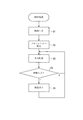
図3は、ノートPC3の制御処理を示すフローチャートである。
画像表示システム1の使用者が操作手段32を介してノートPC3の制御処理を実行すると、ノートPC3は、メインメモリー331に記憶された制御プログラムを実行する。
ノートPC3にて制御プログラムが実行されると、図3に示すように、画面生成部332は、複数の仮想画面に係る画像情報を生成する(S1:画面生成ステップ)。なお、本実施形態では、仮想画面の数は、制御処理を実行する際に使用者が操作手段32を介して入力するものとし、画面生成部332は、4つの仮想画面を生成するものとして説明する。
[Note PC control processing]
Next, control processing of the
FIG. 3 is a flowchart showing the control process of the
When the user of the
When the control program is executed on the
画面生成ステップS1にて各仮想画面が生成されると、検出部333は、ノートPC3に接続される各プロジェクター2を検出する(S2:検出ステップ)。なお、本実施形態では、検出部333は、ノートPC3に接続された各プロジェクター2を検出した順に識別番号を付すものとし、各プロジェクター2には、それぞれPJ1〜PJ4の識別番号が付されたものとする。
検出ステップS2にて各プロジェクター2が検出されると、表示制御部334は、画面生成部332にて生成される各仮想画面を表示手段31に表示させる(S3:表示制御ステップ)。
When each virtual screen is generated in the screen generation step S1, the
When each
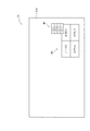
図4は、表示手段31に表示される各仮想画面を示す図である。
表示制御部334は、図4に示すように、画面生成部332にて生成された各仮想画面のうち、いずれか1つの仮想画面を表示手段31における表示領域31Aの全体に表示させる。また、表示制御部334は、表示領域31Aの右下部分にプレビュー画面PVを表示させる。
プレビュー画面PVは、各仮想画面を表示領域31Aの一部に縮小して表示させたものであり、図4では、表示領域31Aの全体に表示させた仮想画面をメインD0とし、他の3つの仮想画面をそれぞれ仮想D1,D2,D3として示している。
FIG. 4 is a diagram showing each virtual screen displayed on the display means 31.
As shown in FIG. 4, the
The preview screen PV is obtained by reducing each virtual screen to a part of the
また、表示制御部334は、プレビュー画面PVのうち、メインD0に係る画像情報を、全画素を黒色とした所定のパターンの画像情報とし、仮想D1〜D3に係る画像情報の情報量を、各プロジェクター2に出力される画像情報の情報量と比較して低減させる。
なお、画像情報の情報量を低減させる方法としては、画像情報の解像度を低減させたり、画像情報の更新速度を低下させたりする方法を用いることができる。
さらに、表示制御部334は、メインメモリー331に記憶された消去情報に基づいて、各仮想画面D0〜D3を消去する。なお、消去情報は、後述する情報入力ステップS4にてメインメモリー331に記憶される。
Further, the
As a method for reducing the amount of image information, a method for reducing the resolution of image information or reducing the update speed of image information can be used.
Further, the
表示制御ステップS3にて表示領域31Aにプレビュー画面PVが表示されると、情報入力部335は、検出部333にて検出された各プロジェクター2と、各仮想画面D0〜D3とを関連付けるための関連情報を入力させるとともに、後述する関連付けステップS5において、各プロジェクター2に関連付けられた各仮想画面D0〜D3を表示手段31から消去するための消去情報を入力させる(S4:情報入力ステップ)。なお、入力された関連情報、及び消去情報は、メインメモリー331に記憶される。
情報入力ステップS4にて関連情報が入力されると、関連付け部336は、メインメモリー331に記憶された関連情報に基づいて、検出部333にて検出された各プロジェクター2と、各仮想画面D0〜D3とを関連付けて各仮想画面D0〜D3に係る画像情報を各プロジェクター2に出力可能とする(S5:関連付けステップ)。
When the preview screen PV is displayed in the
When the related information is input in the information input step S4, the associating
図5は、情報入力部335にて関連情報を入力している状態を示す図である。
画像表示システム1の使用者が操作手段32を介してプレビュー画面PVにおける各仮想画面D0〜D3のいずれかを選択すると、情報入力部335は、図5に示すように、表示領域31Aにメニュー画面M1を表示させる。なお、図5では、使用者は、仮想画面D1を選択したものとし、メニュー画面M1は、各プロジェクター2に付された識別番号PJ1〜PJ4を表示するリストである。
FIG. 5 is a diagram illustrating a state in which related information is input by the
When the user of the
そして、使用者が操作手段32を介してメニュー画面M1におけるPJ1〜PJ4のいずれかを選択すると、関連付け部336は、選択された識別番号が付されたプロジェクター2と、選択された仮想画面D1とを関連付ける。例えば、識別番号PJ1が付されたプロジェクター2を使用者が選択したとすると、関連付け部336は、仮想画面D1に係る画像情報を識別番号PJ1が付されたプロジェクター2に出力可能とする。
When the user selects any of PJ1 to PJ4 on the menu screen M1 via the
図6は、情報入力部335にて消去情報を入力している状態を示す図である。
識別番号PJ1が付されたプロジェクター2と、仮想画面D1とが関連付けられている場合において、画像表示システム1の使用者が操作手段32を介してプレビュー画面PVにおける仮想画面D1を選択すると、情報入力部335は、図6に示すように、表示領域31Aにメニュー画面M2を表示させる。なお、本実施形態では、識別番号PJ1が付されたプロジェクター2と、仮想画面D1とが関連付けられている状態をメニュー画面M2上の黒丸印で示している。
この場合には、情報入力部335は、メニュー画面M2の最下欄に消去の欄を表示するので、使用者は、メニュー画面M2に表示された消去の欄を選択することで消去情報を入力する。
FIG. 6 is a diagram showing a state in which erasure information is input by the
When the
In this case, the
情報入力ステップS4にて関連情報、及び消去情報のいずれもが入力されない場合や、関連付けステップS5にて関連付けが実行された場合には、ノートPC3は、再度、表示制御ステップS3を実行する。
If neither the related information nor the erasure information is input in the information input step S4, or if the association is executed in the association step S5, the
本実施形態に係るノートPC3によれば、次のような効果がある。
(1)ノートPC3は、画面生成部332にて生成される各仮想画面D0〜D3を表示手段31に表示させる表示制御部334を備えるので、ノートPC3の使用者は、表示手段31を見ることで各仮想画面D0〜D3がどのような画面であるかを確認することができる。そして、ノートPC3は、検出部333と、情報入力部335と、関連付け部336とを備えるので、使用者は、情報入力部335を介して関連情報を入力することで所望のプロジェクター2に対して所望の画面を容易に表示させることができる。
The
(1) Since the
(2)表示制御部334は、表示手段31に表示される各仮想画面D1〜D3に係る画像情報の情報量を、各プロジェクター2に出力される画像情報の情報量と比較して低減させるので、ノートPC3にかかる負荷を低減させることができる。
(3)表示制御部334は、各仮想画面D0〜D3のうち、仮想画面D0を表示手段31における表示領域31Aの全体に表示させるので、使用者の利便性を向上させることができる。
(2) Since the
(3) Since the
(4)表示制御部334は、表示手段31における表示領域31Aの一部に縮小して表示させた各仮想画面D0〜D3のうち、表示手段31における表示領域31Aの全体に表示させた仮想画面D0に係る画像情報を所定のパターンの画像情報とするので、ノートPC3にかかる負荷を低減させることができる。
(5)使用者は、情報入力部335を介して消去情報を入力することで関連付け部336にて各プロジェクター2に関連付けられた各仮想画面D0〜D3を消去することができる。したがって、ノートPC3にかかる負荷を更に低減させることができる。
(4) The
(5) The user can erase the virtual screens D <b> 0 to D <b> 3 associated with each
〔実施形態の変形〕
なお、本発明は前記実施形態に限定されるものではなく、本発明の目的を達成できる範囲での変形、改良等は本発明に含まれるものである。
例えば、前記実施形態では、表示制御部334は、画面生成部332にて生成された各仮想画面のうち、いずれか1つの仮想画面を表示手段31における表示領域31Aの全体に表示させ、表示領域31Aの右下部分にプレビュー画面PVを表示させていた。これに対して、表示制御部は、1つの仮想画面を表示手段における表示領域の全体に表示させなくてもよい。要するに、表示制御部は、画面生成部にて生成される各仮想画面を表示部に表示させればよい。
[Modification of Embodiment]
It should be noted that the present invention is not limited to the above-described embodiment, and modifications, improvements, etc. within a scope that can achieve the object of the present invention are included in the present invention.
For example, in the above-described embodiment, the
前記実施形態では、表示制御部334は、プレビュー画面PVのうち、メインD0に係る画像情報を、全画素を黒色とした所定のパターンの画像情報とし、仮想D1〜D3に係る画像情報の情報量を、各プロジェクター2に出力される画像情報の情報量と比較して低減させていた。これに対して、表示制御部は、各仮想画面に係る画像情報を各表示装置に出力される画像情報と同じ画像情報としてもよい。
前記実施形態では、情報入力部335は、各プロジェクター2に関連付けられた各仮想画面D0〜D3を表示手段31から消去するための消去情報を入力させ、メインメモリー331に記憶された消去情報に基づいて、各仮想画面D0〜D3を消去していた。これに対して、情報入力部、及び表示制御部は、各仮想画面を消去することができるように構成されていなくてもよい。
In the embodiment, the
In the above embodiment, the
前記実施形態では、情報入力部335は、メニュー画面M1,M2を表示させることで関連情報、及び消去情報を入力させていたが、例えば、ボタン等の他のGUI(Graphical User Interface)を表示させることで情報を入力させるように構成してもよい。
前記実施形態では、画面生成部332にて各仮想画面D0〜D3が生成されると、検出部333は、ノートPC3に接続される各プロジェクター2を検出していた。これに対して、検出部は、画像出力装置に新たな表示装置が接続される度に、画像出力装置に接続される表示装置を検出するように構成してもよい。
In the embodiment, the
In the embodiment, when the virtual screens D0 to D3 are generated by the
前記実施形態では、仮想画面の数は、使用者が操作手段32を介して入力することとしたが、検出部333が接続されている表示装置の台数を動的に検出して、仮想画面の数を管理するようにしてもよい。
前記実施形態では、USBケーブル41、及びUSBハブ42で構成される伝送手段4を例示したが、画像情報を伝送するのに十分な帯域を確保できるものであればよく、LAN(Local Area Network)ケーブルとハブ、ワイヤレスLANやワイヤレスUSB等の構成も可能である。
前記実施形態では、表示装置としてプロジェクター2を例示し、画像出力装置としてノートPC3を例示していたが、これら以外の機器であってもよい。要するに、表示装置は、入力される画像情報に基づく画面を表示するものであればよく、画像出力装置は、画像情報に基づく画面を表示する表示部を有し、表示装置に対して画像情報を出力するものであればよい。
In the above-described embodiment, the number of virtual screens is input by the user via the
In the above-described embodiment, the
In the embodiment, the
本発明は、画像出力装置、制御方法、及び制御プログラムに好適に利用することができる。 The present invention can be suitably used for an image output apparatus, a control method, and a control program.
2…プロジェクター(表示装置)、3…ノートPC(画像出力装置)、31…表示手段(表示部)、31A…表示領域、332…画面生成部、333…検出部、334…表示制御部、335…情報入力部、336…関連付け部、D0-D3…仮想画面、S1…画面生成ステップ、S2…検出ステップ、S3…表示制御ステップ、S4…情報入力ステップ、S5…関連付けステップ。 2 ... projector (display device), 3 ... notebook PC (image output device), 31 ... display means (display unit), 31A ... display area, 332 ... screen generation unit, 333 ... detection unit, 334 ... display control unit, 335 ... information input unit, 336 ... association unit, D0-D3 ... virtual screen, S1 ... screen generation step, S2 ... detection step, S3 ... display control step, S4 ... information input step, S5 ... association step.
Claims (6)
表示部と、
それぞれ仮想的な画面である複数の仮想画面に係る画像情報を生成する画面生成部と、
当該画像出力装置に接続された表示装置を検出する検出部と、
入力操作が行われる操作部と、
前記操作部に対して、前記検出部にて検出された前記表示装置と、前記複数の仮想画面のいずれかとを関連付ける入力操作が行われると、当該入力操作に基づいて、前記検出部にて検出された前記表示装置と、前記複数の仮想画面のいずれかとを関連付けて、関連付けがされた前記仮想画面に係る画像情報を、関連付けがされた前記表示装置に出力可能とする関連付け部と、
前記画面生成部にて生成された前記複数の仮想画面を前記表示部に表示させる表示制御部と、を備え、
前記表示制御部は、前記複数の仮想画面のうちいずれか1つの仮想画面を前記表示部における表示領域の全体に表示させるとともに、前記複数の仮想画面のうち前記表示領域の全体に表示されている仮想画面とは異なる少なくとも1つの仮想画面を前記表示領域の一部に縮小して表示させることを特徴とする画像出力装置。 An image output device for outputting image information,
A display unit;
A screen generating unit for generating image information relating to a plurality of virtual screens respectively virtual screen,
A detector for detecting a Viewing device connected to the image output apparatus,
An operation unit where input operation is performed;
Wherein the operation unit, and the display device detected by the detecting unit, when either preparative associated Ru input operation of the plurality of virtual screens is performed, based on the input operation, the detector An association unit that associates the display device detected in step 1 with any one of the plurality of virtual screens and outputs image information related to the associated virtual screen to the associated display device and,
A display control unit that causes the display unit to display the plurality of virtual screens generated by the screen generation unit,
The display control unit displays any one virtual screen of the plurality of virtual screens on the entire display region of the display unit, and is displayed on the entire display region of the plurality of virtual screens. virtual screen image output device according to claim Rukoto be displayed by reducing the at least one different virtual screen on a part of the display area and.
前記表示制御部は、前記表示領域の一部に縮小して表示される前記少なくとも1つの仮想画面のうち、前記表示装置との関連付けがされた仮想画面に係る画像情報の情報量を、当該表示装置に出力される画像情報の情報量と比較して低減させることを特徴とする画像出力装置。 The image output apparatus according to claim 1 ,
The display control unit displays an information amount of image information related to a virtual screen associated with the display device among the at least one virtual screen displayed in a reduced size in a part of the display area. An image output apparatus that reduces the amount of image information that is output to the apparatus.
前記表示制御部は、前記表示領域の一部に縮小して表示された前記仮想画面を、前記表示領域の全体に表示させる際に、前記縮小して表示されていた前記仮想画面を所定のパターン画像とすることを特徴とする画像出力装置。 In the image output device according to claim 1 or 2 ,
The display control unit, when displaying the virtual screen displayed in a reduced size in a part of the display area on the entire display area, displays the virtual screen displayed in a reduced size as a predetermined value. An image output apparatus characterized by being a pattern image.
前記操作部に対して、前記関連付け部にて前記表示装置と関連付けられた前記仮想画面を消去する入力操作が行われると、前記表示制御部は、当該入力操作に応じた前記仮想画面を前記表示領域から消去することを特徴とする画像出力装置。 The image output device according to any one of claims 1 to 3 ,
When an input operation for deleting the virtual screen associated with the display device is performed on the operation unit by the association unit, the display control unit displays the virtual screen according to the input operation. An image output device for deleting from an area.
それぞれ仮想的な画面である複数の仮想画面に係る画像情報を生成する画面生成ステップと、
前記画像出力装置に接続された表示装置を検出する検出ステップと、
前記検出ステップにて検出された前記表示装置と、前記複数の仮想画面のいずれかとを関連付ける入力操作が行われると、当該入力操作に基づいて、前記検出ステップにて検出された前記表示装置と、前記複数の仮想画面のいずれかとを関連付けて、前記仮想画面に係る画像情報を前記表示装置に出力可能とする関連付けステップと、
前記画面生成ステップにて生成された前記複数の仮想画面を表示部に表示させる表示制御ステップと、を含み、
前記表示制御ステップは、前記複数の仮想画面のうち、いずれか1つの仮想画面を前記表示部における表示領域の全体に表示させるとともに、前記複数の仮想画面のうち前記表示領域の全体に表示されている仮想画面とは異なる少なくとも1つの仮想画面を前記表示領域の一部に縮小して表示させることを特徴とする制御方法。 A control method for an image output device that outputs image information,
A screen generation step of generating image information relating to a plurality of virtual screens respectively virtual screen,
A detection step of detecting Viewing apparatus connected to the image output apparatus,
Said detected the display by the detection step device, when either preparative associated Ru input operation of the plurality of virtual screens is performed, based on the input operation, the display detected by the detecting step An association step of associating a device with any one of the plurality of virtual screens and enabling image information relating to the virtual screen to be output to the display device ;
A display control step of causing the display unit to display the plurality of virtual screens generated in the screen generation step,
The display control step displays any one virtual screen of the plurality of virtual screens on the entire display area of the display unit and is displayed on the entire display area of the plurality of virtual screens. A control method comprising: displaying at least one virtual screen that is different from a virtual screen being displayed on a part of the display area .
前記画像出力装置に、
それぞれ仮想的な画面である複数の仮想画面に係る画像情報を生成する画面生成ステップと、
前記画像出力装置に接続された表示装置を検出する検出ステップと、
前記検出ステップにて検出された前記表示装置と、前記複数の仮想画面のいずれかとを関連付ける入力操作が行われると、当該入力操作に基づいて、前記検出ステップにて検出された前記表示装置と、前記複数の仮想画面のいずれかとを関連付けて、前記仮想画面に係る画像情報を前記表示装置に出力可能とする関連付けステップと、
前記画面生成ステップにて生成された前記複数の仮想画面を表示部に表示させる表示制御ステップと、を実行させ、
前記表示制御ステップは、前記複数の仮想画面のうち、いずれか1つの仮想画面を前記表示部における表示領域の全体に表示させるとともに、前記複数の仮想画面のうち前記表示領域の全体に表示されている仮想画面とは異なる少なくとも1つの仮想画面を前記表示領域の一部に縮小して表示させることを特徴とする制御プログラム。 A control program for an image output device that outputs image information,
In the image output device,
A screen generation step of generating image information relating to a plurality of virtual screens respectively virtual screen,
A detection step of detecting Viewing apparatus connected to the image output apparatus,
Said detected the display by the detection step device, when either preparative associated Ru input operation of the plurality of virtual screens is performed, based on the input operation, the display detected by the detecting step An association step of associating a device with any one of the plurality of virtual screens and enabling image information relating to the virtual screen to be output to the display device ;
A display control step of causing the display unit to display the plurality of virtual screens generated in the screen generation step;
The display control step displays any one virtual screen of the plurality of virtual screens on the entire display area of the display unit and is displayed on the entire display area of the plurality of virtual screens. A control program for displaying at least one virtual screen different from the existing virtual screen by reducing it to a part of the display area .
Priority Applications (2)
| Application Number | Priority Date | Filing Date | Title |
|---|---|---|---|
| JP2009072108A JP5515351B2 (en) | 2009-03-24 | 2009-03-24 | Image output apparatus, control method, and control program |
| US12/729,576 US20100245208A1 (en) | 2009-03-24 | 2010-03-23 | Image output device, control method and control program |
Applications Claiming Priority (1)
| Application Number | Priority Date | Filing Date | Title |
|---|---|---|---|
| JP2009072108A JP5515351B2 (en) | 2009-03-24 | 2009-03-24 | Image output apparatus, control method, and control program |
Publications (3)
| Publication Number | Publication Date |
|---|---|
| JP2010224276A JP2010224276A (en) | 2010-10-07 |
| JP2010224276A5 JP2010224276A5 (en) | 2012-05-17 |
| JP5515351B2 true JP5515351B2 (en) | 2014-06-11 |
Family
ID=42783506
Family Applications (1)
| Application Number | Title | Priority Date | Filing Date |
|---|---|---|---|
| JP2009072108A Active JP5515351B2 (en) | 2009-03-24 | 2009-03-24 | Image output apparatus, control method, and control program |
Country Status (2)
| Country | Link |
|---|---|
| US (1) | US20100245208A1 (en) |
| JP (1) | JP5515351B2 (en) |
Families Citing this family (2)
| Publication number | Priority date | Publication date | Assignee | Title |
|---|---|---|---|---|
| JP6275075B2 (en) * | 2015-04-02 | 2018-02-07 | キヤノン株式会社 | Projection apparatus, control method, and program |
| CN108989874B (en) * | 2018-09-11 | 2021-04-16 | 创维集团智能科技有限公司 | Intelligent display with projection function, implementation method thereof and intelligent television |
Family Cites Families (10)
| Publication number | Priority date | Publication date | Assignee | Title |
|---|---|---|---|---|
| JP4101476B2 (en) * | 2001-05-24 | 2008-06-18 | 株式会社東芝 | Camera monitoring system, video selection control device, and video selection control method |
| US20030179240A1 (en) * | 2002-03-20 | 2003-09-25 | Stephen Gest | Systems and methods for managing virtual desktops in a windowing environment |
| US7948448B2 (en) * | 2004-04-01 | 2011-05-24 | Polyvision Corporation | Portable presentation system and methods for use therewith |
| JP2006284990A (en) * | 2005-04-01 | 2006-10-19 | Matsushita Electric Ind Co Ltd | Image transmission multi-display system |
| JP2007240813A (en) * | 2006-03-08 | 2007-09-20 | Seiko Epson Corp | System, device, method and program for displaying image |
| US8436943B2 (en) * | 2007-03-22 | 2013-05-07 | Control4 Corporation | System and method for automated audio visual system control |
| JP2008293225A (en) * | 2007-05-24 | 2008-12-04 | Nec Corp | Image switching method and system |
| US8543935B2 (en) * | 2008-08-20 | 2013-09-24 | Red Hat, Inc. | Full-screen heterogeneous desktop display and control |
| WO2010021047A1 (en) * | 2008-08-21 | 2010-02-25 | Necディスプレイソリューションズ株式会社 | Image display system, image providing device, image output device, information terminal, image display method and program |
| US9253430B2 (en) * | 2009-01-15 | 2016-02-02 | At&T Intellectual Property I, L.P. | Systems and methods to control viewed content |
-
2009
- 2009-03-24 JP JP2009072108A patent/JP5515351B2/en active Active
-
2010
- 2010-03-23 US US12/729,576 patent/US20100245208A1/en not_active Abandoned
Also Published As
| Publication number | Publication date |
|---|---|
| JP2010224276A (en) | 2010-10-07 |
| US20100245208A1 (en) | 2010-09-30 |
Similar Documents
| Publication | Publication Date | Title |
|---|---|---|
| JP7042622B2 (en) | Image processing device, image processing system, image processing method, and program | |
| JP5812758B2 (en) | Information processing apparatus, control method therefor, and program | |
| US10649754B2 (en) | Image processing device and electronic whiteboard | |
| JP2011034568A (en) | Display system, display method, program, and recording medium | |
| JP2011097336A (en) | Presentation system, and display device of presentation system | |
| JP5779085B2 (en) | Information processing apparatus, screen output system, screen output control method, and program | |
| JP6946690B2 (en) | Display device, display method and program | |
| JP6160305B2 (en) | Image processing apparatus, program, image processing system, and image processing method | |
| JP5935456B2 (en) | Image processing device | |
| US10725653B2 (en) | Image processing device, image processing system, and image processing method | |
| JP2005148450A (en) | Display controller and program | |
| JP5515351B2 (en) | Image output apparatus, control method, and control program | |
| US20160127584A1 (en) | Image forming apparatus, method for controlling image forming apparatus, and storage medium for performing printing based on collection settings | |
| US10114518B2 (en) | Information processing system, information processing device, and screen display method | |
| US20160307349A1 (en) | Communication support system, information processing apparatus, control method, and storage medium | |
| JP2021064832A5 (en) | ||
| JP2016115308A (en) | Preview display, printer, preview display method, printing method, preview display program and storage medium | |
| JP7419958B2 (en) | Information processing device, service integration system, service integration method and program | |
| JP5755716B2 (en) | Display device and projection display device | |
| JP5213033B2 (en) | Software input key display method, program, and information processing terminal | |
| KR100769677B1 (en) | Control methods of image forming apparatus and system | |
| JP5590995B2 (en) | Image processing apparatus and control method thereof | |
| JP6061882B2 (en) | Image forming apparatus and application screen display method of image forming apparatus | |
| CN107924295A (en) | Wide view image display system, information processor and method for displaying image | |
| JP6784953B2 (en) | Information processing equipment and programs |
Legal Events
| Date | Code | Title | Description |
|---|---|---|---|
| A521 | Written amendment |
Free format text: JAPANESE INTERMEDIATE CODE: A523 Effective date: 20120322 |
|
| A621 | Written request for application examination |
Free format text: JAPANESE INTERMEDIATE CODE: A621 Effective date: 20120322 |
|
| A977 | Report on retrieval |
Free format text: JAPANESE INTERMEDIATE CODE: A971007 Effective date: 20130516 |
|
| A131 | Notification of reasons for refusal |
Free format text: JAPANESE INTERMEDIATE CODE: A131 Effective date: 20130702 |
|
| A521 | Written amendment |
Free format text: JAPANESE INTERMEDIATE CODE: A523 Effective date: 20130830 |
|
| TRDD | Decision of grant or rejection written | ||
| A01 | Written decision to grant a patent or to grant a registration (utility model) |
Free format text: JAPANESE INTERMEDIATE CODE: A01 Effective date: 20140304 |
|
| A61 | First payment of annual fees (during grant procedure) |
Free format text: JAPANESE INTERMEDIATE CODE: A61 Effective date: 20140317 |
|
| R150 | Certificate of patent or registration of utility model |
Ref document number: 5515351 Country of ref document: JP Free format text: JAPANESE INTERMEDIATE CODE: R150 |
|
| S531 | Written request for registration of change of domicile |
Free format text: JAPANESE INTERMEDIATE CODE: R313531 |
|
| R350 | Written notification of registration of transfer |
Free format text: JAPANESE INTERMEDIATE CODE: R350 |