JP5514761B2 - Sheet feeding apparatus and image forming apparatus - Google Patents
Sheet feeding apparatus and image forming apparatus Download PDFInfo
- Publication number
- JP5514761B2 JP5514761B2 JP2011073346A JP2011073346A JP5514761B2 JP 5514761 B2 JP5514761 B2 JP 5514761B2 JP 2011073346 A JP2011073346 A JP 2011073346A JP 2011073346 A JP2011073346 A JP 2011073346A JP 5514761 B2 JP5514761 B2 JP 5514761B2
- Authority
- JP
- Japan
- Prior art keywords
- sheet
- conveyance path
- document
- tray
- unit
- Prior art date
- Legal status (The legal status is an assumption and is not a legal conclusion. Google has not performed a legal analysis and makes no representation as to the accuracy of the status listed.)
- Active
Links
Images


Landscapes
- Sheets, Magazines, And Separation Thereof (AREA)
Description
本発明は、シートを所定の処理位置へ向けて給紙させるシート給紙装置、及びそのシート給紙装置を自動原稿給紙装置として備えた画像形成装置に関する。 The present invention relates to a sheet feeding device that feeds a sheet toward a predetermined processing position, and an image forming apparatus that includes the sheet feeding device as an automatic document feeding device.
シート給紙装置は、トレイに積み重ねて載置された複数枚のシートを、一枚ずつピックアップして搬送路に送り出す機能を有し、例えば、画像形成装置の自動原稿給紙装置(ADF:Auto Document Feeder)として利用される。自動原稿給紙装置を用いれば、画像形成装置において、複数枚の原稿シートを自動的に連続してスキャンすることができる。 The sheet feeding device has a function of picking up a plurality of sheets stacked and placed on a tray one by one and sending them out to a conveyance path. For example, an automatic document feeding device (ADF: Auto) of an image forming apparatus. Used as Document Feeder). If the automatic document feeder is used, the image forming apparatus can automatically and continuously scan a plurality of document sheets.
自動原稿給紙装置は、搬送路の上流側から順に配置されたピックアップローラー、分離機構(給送ベルト、分離ローラー)、レジストローラー及び搬送ローラー等を備える(例えば、特許文献1参照)。ピックアップローラーは、トレイに載置された複数枚の原稿シートの一番上の原稿シートを取り出す。分離機構は、取り出された一番上の原稿シートとそれより下の原稿シートを分離して、一番上の原稿シートだけを搬送路に送り出す。レジストローラーは、搬送路に送り出された原稿シートが斜めに搬送されないように、原稿シートの傾きを補正する。レジストローラーで傾きが補正された原稿シートは、搬送ローラーにより搬送路上を搬送されて画像読取位置に送られる。 The automatic document feeder includes a pickup roller, a separation mechanism (feed belt, separation roller), a registration roller, a conveyance roller, and the like arranged in order from the upstream side of the conveyance path (see, for example, Patent Document 1). The pickup roller picks up the uppermost document sheet from the plurality of document sheets placed on the tray. The separation mechanism separates the extracted uppermost original sheet from the lower original sheet, and sends out only the uppermost original sheet to the conveyance path. The registration roller corrects the inclination of the document sheet so that the document sheet sent to the conveyance path is not conveyed obliquely. The original sheet whose inclination is corrected by the registration roller is conveyed on the conveyance path by the conveyance roller and is sent to the image reading position.
搬送路を搬送される原稿シートと搬送路に次に送り出す原稿シートとのシート間隔を小さくし、連続して原稿シートを搬送路に送り出せば、最初の原稿シートの給紙を開始してから最後の原稿シートの給紙が終わるまでの時間を短くすることができる。 If the sheet interval between the original sheet transported on the transport path and the next original sheet to be sent to the transport path is reduced and the original sheets are continuously sent to the transport path, feeding of the first original sheet is started and the last is started. It is possible to shorten the time until the document sheet is completely fed.
次の原稿シートを送り出すタイミングの判定には、フィードスイッチが利用される。フィードスイッチが、搬送路を搬送される原稿シートの後端を検知(フィードスイッチがオンからオフに切り換わる)することを条件として、次の原稿シートを搬送路に送り出すタイミングが決められる。従って、搬送路を搬送される原稿シートと搬送路に次に送り出す原稿シートとのシート間隔を小さくするには、フィードスイッチを搬送路の上流側に配置する必要がある。 A feed switch is used to determine the timing for sending out the next document sheet. On the condition that the feed switch detects the trailing edge of the document sheet conveyed on the conveyance path (the feed switch switches from on to off), the timing for sending the next document sheet to the conveyance path is determined. Therefore, in order to reduce the sheet interval between the original sheet conveyed on the conveyance path and the original sheet sent next to the conveyance path, it is necessary to dispose the feed switch on the upstream side of the conveyance path.
しかし、搬送路の上流には上述した分離機構が配置されているので、フィードスイッチを分離機構の横に並べて配置することになる。分離機構は搬送路のセンターライン上に配置されるので、フィードスイッチを分離機構に並べて配置すると、サイズの小さい原稿シート(例えば、葉書)は、フィードスイッチで検知できなくなる場合がある。 However, since the separation mechanism described above is disposed upstream of the conveyance path, the feed switch is disposed side by side with the separation mechanism. Since the separation mechanism is arranged on the center line of the conveyance path, if the feed switch is arranged side by side with the separation mechanism, a small original sheet (for example, a postcard) may not be detected by the feed switch.
サイズの小さい原稿シートについて、原稿シートの長辺を搬送方向と直角にすれば、サイズの小さい原稿シートでもフィードスイッチで検知することが可能となる。しかし、原稿シートの短辺が搬送方向になるので、搬送ローラーの数を増やす必要がある。 For a small original sheet, if the long side of the original sheet is perpendicular to the conveying direction, even a small original sheet can be detected by the feed switch. However, since the short side of the document sheet is in the transport direction, it is necessary to increase the number of transport rollers.
上記先行技術では、フィードスイッチが分離機構よりも搬送路の下流に配置されているので、小さいサイズの原稿シートでも検知できるが、原稿シートの間隔を小さくして連続して搬送路に送り出すことができない。 In the above prior art, since the feed switch is arranged downstream of the conveyance path from the separation mechanism, even a small-size original sheet can be detected, but the distance between the original sheets can be reduced and continuously sent to the conveyance path. Can not.
本発明は、予め定められたサイズ以上の複数枚のシートについては、シート間隔を小さくして連続して搬送路に送り出すことができる共に予め定められたサイズより小さい複数枚のシートについても、連続して搬送路に送り出すことができるシート給紙装置及びそれを備えた画像形成装置を提供することを目的とする。 In the present invention, a plurality of sheets having a predetermined size or more can be continuously sent out to the conveying path with a small sheet interval, and a plurality of sheets smaller than a predetermined size can be continuously sent. It is an object of the present invention to provide a sheet feeding device that can be sent out to a conveyance path and an image forming apparatus including the sheet feeding device.
上記目的を達成する本発明の一の局面に係る画像形成装置は、給紙されるシートが載置されるトレイと、搬送路と、前記トレイに複数枚のシートが積み重ねて載置されている場合、一番上のシートをそれより下のシートと分離する分離機構を含み、前記トレイに載置されたシートを前記搬送路に送り出す送出手段と、前記搬送路を搬送されるシートの搬送方向と交差する方向に前記分離機構と並べて配置され、前記搬送路を搬送されるシートのうち予め定められたサイズ以上のシートを検知できる第1の検知手段と、前記第1の検知手段で検知できない前記予め定められたサイズより小さいシートを検知できる位置であって、前記分離機構より前記搬送路の下流に設けられた第2の検知手段と、前記予め定められたサイズ以上の複数枚のシートを連続して前記トレイから前記搬送路に送り出す第1のモードと、前記予め定められたサイズより小さい複数枚のシートを連続して前記トレイから前記搬送路に送り出す第2のモードを実行する給紙制御部と、を備え、前記給紙制御部は、前記第1のモードの場合、前記搬送路を搬送されるシートの後端が前記第1の検知手段で検知されることを条件に、前記送出手段に次のシートを前記トレイから前記搬送路に送り出させ、前記第2のモードの場合、前記搬送路を搬送されるシートが前記第2の検知手段で検知されることを条件に、前記送出手段に次のシートを前記トレイから前記搬送路に送り出させる。 An image forming apparatus according to one aspect of the present invention that achieves the above object includes a tray on which a sheet to be fed is placed, a conveyance path, and a plurality of sheets stacked on the tray. A separating mechanism that separates the uppermost sheet from a lower sheet; a feeding unit that feeds the sheet placed on the tray to the conveyance path; and a conveyance direction of the sheet conveyed through the conveyance path The first detection means that is arranged side by side with the separation mechanism in a direction crossing the line and can detect a sheet having a predetermined size or more out of the sheets conveyed on the conveyance path, and cannot be detected by the first detection means A position where a sheet smaller than the predetermined size can be detected, and a second detection means provided downstream of the conveying path from the separation mechanism, and a plurality of sheets having a predetermined size or more. A first mode in which a sheet is continuously sent from the tray to the transport path, and a second mode in which a plurality of sheets smaller than the predetermined size are continuously sent from the tray to the transport path. A paper control unit, and in the first mode, the paper feed control unit is configured on the condition that a rear end of a sheet conveyed on the conveyance path is detected by the first detection unit. In the second mode, the next sheet is sent out from the tray to the conveyance path, and in the second mode, on the condition that the sheet conveyed through the conveyance path is detected by the second detection means. The sending means feeds the next sheet from the tray to the conveyance path.
本発明の一の局面に係るシート給紙装置では、第1の検知手段で検知できる予め定められたサイズ以上の複数枚のシートを連続してトレイから搬送路に送り出す場合(第1のモードの場合)、搬送路を搬送されるシートの後端が第1の検知手段で検知されることを条件に、次のシートをトレイから搬送路に送り出し、第1の検知手段で検知できない予め定められたサイズより小さい複数枚のシートを連続してトレイから搬送路に送り出す場合(第2のモードの場合)、搬送路を搬送されるシートが第2の検知手段で検知されることを条件に、次のシートをトレイから搬送路に送り出す。このように本発明の一の局面によれば、シート間隔を小さくするために第1の検知手段を分離機構と並べて配置した場合に、第1の検知手段で検知できないサイズのシートについては、第2の検知手段を用いて検知することを条件に、次のシートを送り出している。従って、予め定められたサイズ以上の複数枚のシートについては、シート間隔を小さくして連続して搬送路に送り出すことができる共に予め定められたサイズより小さい複数枚のシートについても、連続して搬送路に送り出すことができる。 In the sheet feeding device according to one aspect of the present invention, when a plurality of sheets having a predetermined size or more that can be detected by the first detection unit are continuously sent out from the tray to the conveyance path (in the first mode). In the case where the trailing edge of the sheet conveyed on the conveyance path is detected by the first detection unit, the next sheet is sent from the tray to the conveyance path and cannot be detected by the first detection unit. When a plurality of sheets smaller than the predetermined size are continuously sent from the tray to the conveyance path (in the second mode), on condition that the sheet conveyed through the conveyance path is detected by the second detection unit, The next sheet is sent out from the tray to the conveyance path. As described above, according to one aspect of the present invention, when the first detection unit is arranged side by side with the separation mechanism to reduce the sheet interval, the first detection unit cannot detect the size of the sheet. The next sheet is fed out on condition that it is detected using the second detecting means. Therefore, for a plurality of sheets having a predetermined size or more, the sheet interval can be continuously reduced and sent to the conveyance path, and for a plurality of sheets having a size smaller than the predetermined size, It can be sent out to the conveyance path.
上記構成において、前記第2のモードの場合、前記搬送路を搬送されるシートは、当該シートの長辺方向が搬送方向にされている。 In the above configuration, in the case of the second mode, the long side direction of the sheet conveyed through the conveyance path is set to the conveyance direction.
この構成によれば、予め定められたサイズより小さいシートは、シートの長辺方向を搬送方向にしているので、搬送ローラーの数を増やさなくても、シートを搬送することが可能となる。 According to this configuration, since the sheet having a smaller size than the predetermined size has the long side direction of the sheet as the transport direction, the sheet can be transported without increasing the number of transport rollers.
上記構成において、前記搬送路は、搬送されるシートの一方の面の画像が光学的に読み取られる画像読取位置を経由する搬送路であって、前記画像読取位置より上流であって前記第2の検知手段より下流の前記搬送路に配置され、前記搬送路を搬送されるシートの他方の面の画像を読み取る接触型撮像素子をさらに備え、前記第2の検知手段は、前記撮像素子により前記搬送路を搬送されるシートの他方の面の画像を読み取る場合のタイミングの検知に用いられる。 In the above configuration, the conveyance path is a conveyance path that passes through an image reading position where an image on one surface of the conveyed sheet is optically read, and is upstream of the image reading position and the second path. A contact-type image sensor that is disposed in the transport path downstream from the detection unit and reads an image on the other surface of the sheet transported through the transport path is further provided, and the second detection unit is configured to transport the transport by the image sensor. This is used for timing detection when an image on the other surface of the sheet conveyed on the path is read.
この構成によれば、接触型撮像素子により搬送路を搬送されるシートの他方の面の画像を読み取る場合のタイミングの検知に用いられる検知手段を第2の検知手段にしている。このため、予め定められたサイズより小さい原稿シートを検知するために、第2の検知手段を新たに設ける必要がなくなる。接触型撮像素子とは、例えば、CIS(Contact Image Sensor)をいう。 According to this configuration, the detection means used for detecting the timing when the image on the other surface of the sheet conveyed on the conveyance path by the contact-type imaging device is read is the second detection means. For this reason, it is not necessary to newly provide a second detection means in order to detect an original sheet smaller than a predetermined size. The contact-type image sensor refers to, for example, a CIS (Contact Image Sensor).
また、この構成によれば、接触型撮像素子を画像読取位置より上流に配置されているので、接触型撮像素子を画像読取位置より下流に配置されている場合に比べて、第2の検知手段を搬送路の上流側に配置することができる。従って、接触型撮像素子を画像読取位置より下流に配置されている場合に比べて、予め定められたサイズより小さい複数枚のシートを、シート間隔を小さくして連続して搬送路に送り出すことが可能となる。 Further, according to this configuration, since the contact-type image sensor is arranged upstream from the image reading position, the second detection unit is compared with the case where the contact-type image sensor is arranged downstream from the image reading position. Can be arranged upstream of the transport path. Therefore, a plurality of sheets smaller than a predetermined size can be continuously sent out to the conveyance path with a reduced sheet interval as compared with the case where the contact-type imaging device is arranged downstream from the image reading position. It becomes possible.
上記構成において、前記分離機構より下流であって前記第2の検知手段より上流の前記搬送路に配置されたレジストローラーと、前記給紙制御部により制御されて、前記レジストローラーを回転させるレジスト駆動手段と、を備え、前記給紙制御部は、前記第1のモードの場合、前記送出手段を制御して前記トレイに載置されたシートを前記搬送路に送り出して、前記レジストローラーにより当該シートの傾きを補正した後、前記レジスト駆動手段を制御して前記レジストローラーを回転させて当該シートを前記搬送路の下流へ搬送し、前記第2のモードの場合、前記送出手段を制御して前記トレイに載置されたシートを前記搬送路に送り出す動作の開始と同時又は開始より早く前記レジスト駆動手段を制御して前記レジストローラーを回転させて、当該シートを前記搬送路の下流へ搬送可能にする。 In the above configuration, a registration roller disposed in the conveyance path downstream from the separation mechanism and upstream from the second detection unit, and a registration drive that rotates the registration roller under the control of the paper feed control unit. And, in the first mode, the sheet feeding control unit controls the feeding unit to send the sheet placed on the tray to the conveyance path, and the sheet is transferred by the registration roller. After correcting the inclination, the registration driving unit is controlled to rotate the registration roller to convey the sheet downstream of the conveyance path. In the second mode, the feeding unit is controlled to control the feeding unit. The registration roller is rotated by controlling the registration driving means at the same time as or earlier than the start of feeding the sheet placed on the tray to the conveyance path. So it allows conveying the sheet to the downstream of the conveying path.
第1の検知手段でシートの先端を検知してから所定のタイミングで送出手段を停止させることにより、レジストローラーにシートの先端を当てた状態でシートをたわませる。これにより、レジストローラーでシートの先端の傾きが補正される。第2のモードの場合、第1の検知手段でシートを検知できないので、レジストローラーでシートの先端の傾きを補正することなく、搬送路の下流へ送る。レジストローラーを送出手段の動作よりも後に回転させると、シートがレジストローラーで止められ、シートが搬送路につまる可能性がある。この構成によれば、レジストローラーを送出手段の動作と同時又はそれより早く回転させるので、レジストローラーでシートがつまることを防止できる。 By detecting the leading edge of the sheet with the first detection means and stopping the feeding means at a predetermined timing, the sheet is bent with the leading edge of the sheet applied to the registration roller. Thereby, the inclination of the leading edge of the sheet is corrected by the registration roller. In the second mode, since the sheet cannot be detected by the first detection unit, the sheet is sent downstream of the conveyance path without correcting the inclination of the leading edge of the sheet by the registration roller. If the registration roller is rotated after the operation of the feeding means, the sheet may be stopped by the registration roller, and the sheet may be jammed in the conveyance path. According to this configuration, since the registration roller is rotated simultaneously with or faster than the operation of the feeding unit, it is possible to prevent the registration roller from jamming the sheet.
上記構成において、前記給紙制御部は、前記第2のモードの場合、前記搬送路を搬送されるシートの先端が前記第2の検知手段で検知されることを条件に、前記送出手段を制御して次のシートを前記トレイから前記搬送路に送り出させる。 In the above-described configuration, in the second mode, the sheet feeding control unit controls the sending unit on the condition that the leading edge of the sheet conveyed on the conveyance path is detected by the second detecting unit. Then, the next sheet is sent out from the tray to the conveyance path.
この構成によれば、搬送路を搬送されるシートの後端が第2の検知手段で検知されることを条件に、送出手段を制御して次のシートをトレイから搬送路に送り出させる場合に比べて、シート間隔を短くすることができる。 According to this configuration, when the trailing edge of the sheet conveyed on the conveyance path is detected by the second detection unit, the feeding unit is controlled to send the next sheet from the tray to the conveyance path. In comparison, the sheet interval can be shortened.
本発明の他の局面に係る画像形成装置は、上記シート給紙装置と、前記シート給紙装置から給紙されたシートの画像を読み取る画像読取部と、前記画像読取部で読み取られた画像を用紙に形成して出力する装置本体と、を備える。 An image forming apparatus according to another aspect of the present invention includes the sheet feeding device, an image reading unit that reads an image of a sheet fed from the sheet feeding device, and an image read by the image reading unit. An apparatus main body that forms and outputs on a sheet.
本発明の他の局面に係る画像形成装置によれば、上述した本発明の一の局面に係るシート給紙装置と同様の作用を有する。 The image forming apparatus according to another aspect of the present invention has the same operation as that of the sheet feeding apparatus according to one aspect of the present invention described above.
本発明によれば、予め定められたサイズ以上の複数枚のシートについては、シート間隔を小さくして連続して搬送路に送り出すことができる共に予め定められたサイズより小さい複数枚のシートについても、連続して搬送路に送り出すことができる。 According to the present invention, for a plurality of sheets having a predetermined size or more, the sheet interval can be reduced and continuously sent to the conveyance path, and also for a plurality of sheets having a size smaller than the predetermined size. , Can be continuously sent out to the conveyance path.
以下、図面に基づいて、本発明の実施形態につき詳細に説明する。図1は、本発明の一実施形態に係る画像形成装置1の外観を示す斜視図、図2は、自動原稿給紙装置3の外観を示す斜視図、図3は、画像形成装置1の内部構造を示す断面図である。ここでは、画像形成装置1として胴内排紙型の複写機を例示しているが、画像形成装置は、プリンター、ファクシミリ装置、或いは、これらの機能を備える複合機であってもよい。
Hereinafter, embodiments of the present invention will be described in detail with reference to the drawings. FIG. 1 is a perspective view showing an appearance of an
画像形成装置1は、略直方体形状の筐体構造を有し胴内空間(胴内排紙部24)を備えた装置本体2、装置本体2の上面に配置された自動原稿給紙装置3、及び装置本体2の下側に組み付けられた増設給紙ユニット4を含む。
The
装置本体2は、シートに対して画像形成処理を行う。装置本体2は、略直方体形状の下部筐体21と、下部筐体21の上方に配設される略直方体形状の上部筐体22と、下部筐体21と上部筐体22とを連結する連結筐体23とを含む。下部筐体21には画像形成のための各種機器が収容され、上部筐体22には原稿画像を光学的に読み取るための画像読取部5が収容されている。下部筐体21、上部筐体22及び連結筐体23で囲まれる胴内空間が、画像形成後のシートを収容可能な胴内排紙部24とされている。連結筐体23は、装置本体2の右側面の側に配置され、胴内排紙部24へシートを排出するための排出口961が設けられている。
The apparatus
胴内排紙部24として利用される前記胴内空間は、装置本体2の前面及び左側面において外部に開放されている。ユーザーは、これらの開放部分から手を差し入れ、胴内排紙部24から画像形成後のシートを取り出すことが可能である。前記胴内空間の底面241は、下部筐体21の上面で区画され、排出口961から排出されたシートが積載される。
The in-cylinder space used as the in-cylinder
上部筐体22の前面には、操作パネルユニット25が突出して設けられている。操作パネルユニット25は、テンキー、スタートキーなどを含む操作キー251及びLCDタッチパネル252などを備え、ユーザーからの各種の操作指示の入力を受け付ける。ユーザーは、操作パネルユニット25を通じて、印刷されるシートの枚数等を入力したり、印刷濃度等を入力したりすることができる。
An
下部筐体21には、画像形成処理が施される記録シートを収容する給紙カセット211が装着されている。増設給紙ユニット4もまた、画像形成処理が施される記録シートを収容する給紙カセット41、42を含む。これら給紙カセット211、41、42は、自動給紙用に設けられたカセットであり、大量の記録シートをサイズ別に収容することができる。また、給紙カセット211、41、42は、下部筐体21又は増設給紙ユニット4の前面から手前方向に引出可能である。なお、図3では、下部筐体21の給紙カセット211のみを描いている。
A
装置本体2の右側面には、ユーザーに手差し給紙を行わせるためのマルチトレイユニットMが装着されている。マルチトレイユニットMは、手差しの記録シートが載置される給紙トレイ43と、前記記録シートを下部筐体21内の画像形成部へ搬入する給紙ユニット44とを含む。給紙トレイ43は、その下端部において下部筐体21に対して開閉自在に取り付けられており、不使用時は閉状態とされる。ユーザーは、手差し給紙を行う場合、給紙トレイ43を開き、その上に記録シートを載置する。
A multi-tray unit M is mounted on the right side surface of the apparatus
自動原稿給紙装置3は、装置本体2の上面に、その後側において回動自在に取り付けられている。なお、図3では、この自動原稿給紙装置3の記載を省いている。自動原稿給紙装置3は、装置本体2における所定の画像読取位置(第1のコンタクトガラス222が組み付けられた位置)に向けて、複写される原稿シートを自動給紙する。一方、ユーザーが手置きで原稿シートを所定の画像読取位置(第2のコンタクトガラス223の配置位置)に載置する場合は、自動原稿給紙装置3は上方に開けられる。
The
図2を参照して、自動原稿給紙装置3は、本体ハウジング30(ハウジング)、原稿給紙トレイ31(トレイ)、原稿搬送部32、原稿排紙トレイ33及び原稿反転トレイ31Bを備える。本体ハウジング30は、自動原稿給紙装置3に備えられている各種の機構を収容する筐体であって、原稿搬送部32を収容する左側部分に、上方に隆起した前壁部301及び後壁部302を有すると共に、右側部分に、ほぼフラットな低層部分を備えている。
Referring to FIG. 2, the
原稿給紙トレイ31は、画像読取位置へ給送される原稿シートが載置されるトレイであって、本体ハウジング30の給送口30Hから延出するように、本体ハウジング30に付設されている。原稿給紙トレイ31には、載置された原稿シートの幅合わせを行うための一対のカーソル311が備えられている。
The
原稿搬送部32は、原稿給紙トレイ31上の原稿シートを、画像読取位置を経由して原稿排紙トレイ33まで搬送する搬送路及び搬送機構を備える。原稿搬送部32は、本体ハウジング30の前壁部301及び後壁部302の間の開口に嵌め込まれる上部カバー32Uを含む。これら詳細については、図4等に基づいて後で説明する。
The
原稿排紙トレイ33は、原稿画像が光学的に読み取られた後の原稿シートが排出されるトレイである。本体ハウジング30の右側における前記低層部分の上面が、原稿排紙トレイ33とされている。原稿反転トレイ31Bは、両面に原稿画像を有する原稿シートの読取の際に、当該原稿シートが一時的に排出されるトレイである。
The
続いて、図3に基づいて、装置本体2の内部構造を説明する。下部筐体21の内部には、上方から順に、トナーコンテナー99Y、99M、99C、99K、中間転写ユニット92、画像形成部93、露光ユニット94、及び上述の給紙カセット211が収容されている。
Next, the internal structure of the apparatus
画像形成部93は、フルカラーのトナー像を形成するために、イエロー(Y)、マゼンタ(M)、シアン(C)及びブラック(K)の各トナー像を形成する4つの画像形成ユニット10Y、10M、10C、10Kを備える。各画像形成ユニット10Y、10M、10C、10Kは、感光体ドラム11と、この感光体ドラム11の周囲に配置された、帯電器12、現像装置13、一次転写ローラー14及びクリーニング装置15とを含む。
The
感光体ドラム11は、その軸回りに回転し、その周面に静電潜像及びトナー像が形成される。感光体ドラム11としては、アモルファスシリコン(a−Si)系材料を用いた感光体ドラムを用いることができる。帯電器12は、感光体ドラム11の表面を均一に帯電する。帯電後の感光体ドラム11の周面は、露光ユニット94によって露光され、静電潜像が形成される。
The
現像装置13は、感光体ドラム11上に形成された静電潜像を現像するために、感光体ドラム11の周面にトナーを供給する。現像装置13は、2成分現像剤用のものであり、攪拌ローラー16、17、磁気ローラー18、及び現像ローラー19を含む。攪拌ローラー16、17は、2成分現像剤を攪拌しながら循環搬送することで、トナーを帯電させる。磁気ローラー18の周面には2成分現像剤層が担持され、現像ローラー19の周面には、磁気ローラー18と現像ローラー19との間の電位差によってトナーが受け渡されることにより形成されたトナー層が担持される。現像ローラー19上のトナーは、感光体ドラム11の周面に供給され、前記静電潜像が現像される。
The developing device 13 supplies toner to the peripheral surface of the
一次転写ローラー14は、中間転写ユニット92に備えられている中間転写ベルト921を挟んで感光体ドラム11とニップ部を形成し、感光体ドラム11上のトナー像を中間転写ベルト921上に一次転写する。クリーニング装置15は、トナー像転写後の感光体ドラム11の周面を清掃する。
The
イエロー用トナーコンテナー99Y、マゼンタ用トナーコンテナー99M、シアン用トナーコンテナー99C、及びブラック用トナーコンテナー99Kは、それぞれ各色のトナーを貯留するものであり、YMCK各色に対応する画像形成ユニット10Y、10M、10C、10Kの現像装置13に、図略の供給経路を通して各色のトナーを供給する。
The
露光ユニット94は、光源やポリゴンミラー、反射ミラー、偏向ミラーなどの各種の光学系機器を有し、画像形成ユニット10Y、10M、10C、10Kの各々に設けられた感光体ドラム11の周面に、原稿画像の画像データに基づく光を照射して、静電潜像を形成する。
The
中間転写ユニット92は、中間転写ベルト921、駆動ローラー922及び従動ローラー923を備える。中間転写ベルト921上には、複数の感光体ドラム11からトナー像が重ね塗りされる(一次転写)。重ね塗りされたトナー像は、給紙カセット211から供給される記録シートに、二次転写部98において二次転写される。中間転写ベルト921を周回駆動させる駆動ローラー922及び従動ローラー923は、下部筐体21によって回転自在に支持される。
The
給紙カセット211(41、42)は、複数の記録シートが積層されてなるシート束を収納する。給紙カセット211の右端側の上部には、ピックアップローラー212が配置されている。ピックアップローラー212の駆動により、給紙カセット211内のシート束の最上層の記録シートが1枚ずつ繰り出され、搬入搬送路26へ搬入される。一方、給紙トレイ43に載置された手差しの記録シートは、給紙ユニット44の給紙ローラー45の駆動によって、搬入搬送路26へ搬入される。
The paper feed cassette 211 (41, 42) stores a sheet bundle in which a plurality of recording sheets are stacked. A
搬入搬送路26の下流側には、二次転写部98、後述する定着ユニット97及び排紙ユニット96を経由して排出口961まで延びるシート搬送路28が設けられている。シート搬送路28の上流部分は、下部筐体21に形成された内壁と、反転搬送ユニット29の内側面を形成する内壁との間に形成されている。なお、反転搬送ユニット29の外側面は、両面印刷の際にシートを反転搬送する反転搬送路291の片面を構成している。シート搬送路28の、二次転写部98よりも上流側にはレジストローラー対27が配置されている。シートは、レジストローラー対27にて一旦停止され、スキュー矯正が行われた後、画像転写のための所定のタイミングで、二次転写部98に送り出される。
On the downstream side of the carry-in
連結筐体23の内部には、定着ユニット97と排紙ユニット96とが収納されている。定着ユニット97は、定着ローラーと加圧ローラーとを含み、二次転写部98においてトナー像が二次転写された記録シートを加熱及び加圧することで、定着処理を施す。定着処理されたカラー画像付の記録シートは、定着ユニット97の下流に配置されている排紙ユニット96により、排出口961から胴内排紙部24に向けて排出される。
A fixing
上部筐体22の上面には、第1のコンタクトガラス222と第2のコンタクトガラス223とが嵌め込まれている。第1のコンタクトガラス222は、自動原稿給紙装置3から自動給送される原稿シートの読取用に設けられている。第2のコンタクトガラス223は、手置きされる原稿シートの読取用に設けられている。
A
上部筐体22の内部には、画像読取装置5が収容されている。画像読取装置5は、原稿シートの原稿情報を光学的に読み取るための走査機構224とCCD(Charge Coupled Device)225とを備える。走査機構224は、光源、移動キャリッジ、反射ミラー等を含み、原稿からの反射光をCCD225に導く。CCD225は、前記反射光をアナログ電気信号に光電変換する。前記アナログ電気信号は、A/D変換回路(図略)でデジタル電気信号に変換された後、露光ユニット94に入力される。
The
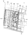
次に、図4及び図5を用いて、自動原稿給紙装置3の内部構造について詳述する。図4は、図2に示す自動原稿給紙装置3の原稿搬送部32において、上部カバー32Uを取り外した状態を示す斜視図である。図5は、図2に示す自動原稿給紙装置3の原稿搬送部32の断面模式図である。なお、原稿シートとは、画像を有するシートであり、例えば、紙のシート及びOHP(overhead projector)シートを含む。
Next, the internal structure of the
原稿搬送部32は、昇降板320、搬送路321、ピックアップローラー324、分離機構325、レジストローラー対326、搬送ローラー対327,328,329及び排紙ローラー対330を備える。
The
搬送路321は、原稿シートが搬送される方向の上流から順に配置された、第1の搬送路321a、第2の搬送路321b及び第3の搬送路321cを備える。原稿給紙トレイ31に載置された原稿シートは、第1の搬送路321a、第2の搬送路321b、第3の搬送路321cを通り、原稿排紙トレイ33に排紙される。
The
昇降板320は、搬送路321の最上流に位置しており、原稿給紙トレイ31と第1の搬送路321aとの間に、昇降可能に設けられている。ピックアップローラー324は、昇降板320と第1の搬送路321aの境界であって昇降板320の上方に配置されている。
The elevating
原稿給紙トレイ31に載置された原稿シートは、その先端部が昇降板320上に位置する。昇降板320を上昇させて、原稿シートの先端部をピックアップローラー324と接触させる。この状態で、ピックアップローラー324が回転すると、原稿給紙トレイ31に載置された原稿シート(複数枚の原稿シートの場合は一番上の原稿シート)がピックアップされて、第1の搬送路321aへ送り出される。
The leading edge of the document sheet placed on the
昇降板320の下面のうち、昇降板320と第1の搬送路321aの境界付近に、セットスイッチPD1が取り付けられている。セットスイッチPD1は、原稿給紙トレイ31に載置された原稿シートの先端部が、ピックアップローラー324と対向する位置にあることを検知するのに用いられる。セットスイッチPD1は、例えば、光センサーであり、その受光面が昇降板320の表面に位置している。
A set switch PD1 is attached to the lower surface of the
昇降面の下面には、原稿給紙トレイ31に載置された原稿のサイズを判定するのに用いられる複数のサイズセンサーが取り付けられている。図4及び図5には、A5サイズより小さいサイズの原稿シート(例えば、葉書)を、その長辺方向が搬送方向にされて、原稿給紙トレイ31に載置されているか否かの判定に用いられるサイズセンサーPD2が表れている。複数のサイズセンサーは、例えば、光センサーであり、その受光面が昇降板320の表面に位置している。
A plurality of size sensors used to determine the size of the document placed on the
第1の搬送路321aは、直線形状を有している。第1の搬送路321aには、上流から順に、分離機構325、レジストローラー対326が配置されており、また、第1の搬送路321aを搬送される原稿シートの搬送方向と交差する方向に分離機構325と並べてフィードスイッチPD3が配置されている。
The
フィードスイッチPD3(第1の検知手段の一例)は、第1の搬送路321aの上方に配置されており、第1の搬送路321aを搬送される原稿シートのうち予め定められたサイズ以上の原稿シート(例えば、A5サイズ以上の原稿シート)の先端と後端の検知に用いられる。以下、A5サイズ以上の原稿シートは、予め定められたサイズ以上の原稿シートを意味し、A5サイズより小さい原稿シートは、予め定められたサイズより小さい原稿シートを意味する。
The feed switch PD3 (an example of the first detection unit) is disposed above the
分離機構325が第1の搬送路321aのセンターライン上に配置されているので、A5サイズより小さい原稿シートは、その長辺方向を搬送方向にすると、フィードスイッチPD3の下方を通過することができない。このため、フィードスイッチPD3は、長辺方向を搬送方向にしたA5サイズより小さい原稿シートについては、検知することができない。
Since the
分離機構325は、第1の搬送路321aのセンターライン上であって、ピックアップローラー324の近傍に配置されている。分離機構325は、駆動ローラー325a、従動ローラー325b、無端ベルト325c及び分離ローラー325dを備える。駆動ローラー325aは、従動ローラー325bよりも下流側に位置している。駆動ローラー325aと従動ローラー325bには、無端ベルト325cが掛け渡されており、これらのローラーは、給紙ローラーとして機能する。駆動ローラー325aと従動ローラー325bの下方には、無端ベルト325cを押圧するように分離ローラー325dが配置されている。
The
ピックアップローラー324及び駆動ローラー325aは、原稿給紙トレイ31に載置された原稿シートを原稿給紙トレイ31から送り出す方向に回転する。これに対して、分離ローラー325dは、原稿給紙トレイ31に載置された原稿シートを原稿給紙トレイ31へ戻す方向に回転する。これらによって、ピックアップローラー324により一枚ずつ取り込まれた原稿シートが複数枚重ねて搬送されるのを防止している。すなわち、分離機構325は、原稿給紙トレイ31に複数枚の原稿シートが積み重ねて載置されている場合、一番上の原稿シートをそれより下の原稿シートと分離する機能を有する。
The
分離機構325の近傍には、レジストローラー対326(レジストローラーの一例)が配置されている。レジストローラー対326は、原稿シートを挟むように配置された駆動ローラー326aと従動ローラー326bから構成される。分離機構325から搬送されてきた原稿シートは、レジストローラー対326により先端の傾きが補正されて、下流へ搬送される。詳細に説明すると、レジストローラー対326の回転が停止された状態で、分離機構325により搬送されてきた原稿シートは、その先端がレジストローラー対326に当たることで、その先端をレジストローラー対326と平行にすることにより、原稿シートの傾きを補正するのである。レジストローラー対326は、分離機構325より下流であって、後で説明するCISタイミングスイッチPD4より上流の搬送路321に配置されている。
A registration roller pair 326 (an example of a registration roller) is disposed in the vicinity of the
第1の搬送路321aと第2の搬送路321bとの境界には、搬送ローラー対327が配置されている。搬送ローラー対327は、原稿シートを挟むように配置された駆動ローラー327aと従動ローラー327bから構成される。レジストローラー対326から搬送されてきた原稿シートは、搬送ローラー対327により、第2の搬送路321bへ搬送される。
A pair of
第2の搬送路321bは、原稿シートの搬送方向を180度変える曲線形状を有する。第2の搬送路321bには、上流から順に、CISタイミングスイッチPD4、CIS350、CCDタイミングスイッチPD5、搬送ローラー対328が配置されている。
The
CIS(Contact Image Sensor)350は、原稿シートに密着して原稿シートの片面(裏面)の画像を読み取る。 A CIS (Contact Image Sensor) 350 reads an image on one side (back side) of a document sheet in close contact with the document sheet.
CISタイミングスイッチPD4(第2の検知手段の一例)は、第2の搬送路321bに配置されている。CISタイミングスイッチPD4は、第2の搬送路321bを搬送される原稿シートの先端を検知し、CISにより原稿シートの片面(裏面)を読み取るタイミングの判定に用いられる。
The CIS timing switch PD4 (an example of the second detection unit) is disposed in the
CISタイミングスイッチPD4は、フィードスイッチPD3で検知できるA5サイズ以上の原稿シート(予め定められたサイズ以上のシート)及びフィードスイッチPD3で検知できない、長辺方向を搬送方向にしたA5サイズより小さい原稿シート(予め定められたサイズより小さいシート)のいずれの検知も可能な位置に配置されている。 The CIS timing switch PD4 is an A5 size or larger document sheet (sheet of a predetermined size or more) that can be detected by the feed switch PD3, and a document sheet that is not detected by the feed switch PD3 and is smaller than the A5 size having the long side direction as the transport direction It is arranged at a position where any detection of (a sheet smaller than a predetermined size) is possible.
CCDタイミングスイッチPD5は、第2の搬送路321bを搬送される原稿シートの先端を検知し、CCD225(図3)により原稿シートの片面(表面)を読み取るタイミングの判定に用いられる。CISタイミングスイッチPD4及びCCDタイミングスイッチPD5は、例えば、光センサーであり、その受光面が第2の搬送路321bの表面に位置している。
The CCD timing switch PD5 detects the leading edge of the document sheet conveyed through the
画像読取位置351は、第2の搬送路321bを搬送される原稿シートの片面(表面)の画像を、CCD225を用いて読み取る場合に画像が読み取られる位置となる。自動原稿給紙装置3を装置本体2に対して閉じると、画像読取位置351は第1のコンタクトガラス222と面する。
The
CCDタイミングスイッチPD5と画像読取位置351との間に、搬送ローラー対328が配置されている。搬送ローラー対328は、原稿シートを挟むように配置された駆動ローラー328aと従動ローラー328bから構成される。原稿シートは、搬送ローラー対328により、第2の搬送路321bを搬送される。
A
第2の搬送路321bと第3の搬送路321cとの境界には、搬送ローラー対329が配置されている。搬送ローラー対329は、原稿シートを挟むように配置された駆動ローラー329aと従動ローラー329bから構成される。第2の搬送路321bを搬送されてきた原稿シートは、搬送ローラー対329により、第3の搬送路321cを搬送される。
A pair of
第3の搬送路321cは、直線状に延びて、途中から斜め上に延びる形状を有する。第3の搬送路321cの終端に、排紙ローラー対330が配置されている。排紙ローラー対330は、原稿シートを挟むように配置された駆動ローラー330aと従動ローラー330bから構成される。第3の搬送路321cを搬送されてきた原稿シートは、排紙ローラー対330により、原稿排紙トレイ33に送られる。
The
図6は、画像形成装置1の構成を示すブロック図である。画像形成装置1は、装置本体2、自動原稿給紙装置3、画像読取部5、操作パネルユニット25及び制御部500がバスによって相互に接続された構成を有する。装置本体2、画像読取部5及び操作パネルユニット25に関しては既に説明したので、説明を省略する。
FIG. 6 is a block diagram illustrating a configuration of the
自動原稿給紙装置3は、既に説明したように、セットスイッチPD1、サイズセンサーPD2、フィードスイッチPD3、CISタイミングスイッチPD4、CCDタイミングスイッチPD5、ピックアップローラー324、分離機構325、レジストローラー対326、搬送ローラー対327,328,329、排紙ローラー対330、及び、CIS350を備える。
As described above, the
自動原稿給紙装置3は、さらに、給紙モーター340、レジストモーター341、搬送モーター342及び排紙モーター343を備える。給紙モーター340により、ピックアップローラー324及び分離機構325が駆動される。給紙モーター340、ピックアップローラー324及び分離機構325によって、送出手段331が構成される。送出手段331は、原稿給紙トレイ31に載置された原稿シートを搬送路321に送り出す機能を有する。
The
レジスト駆動手段の一例であるレジストモーター341によりレジストローラー対326が回転させられ、搬送モーター342により搬送ローラー対327,328,329が回転させられ、排紙モーター343により排紙ローラー対330が回転させられる。
The
制御部500は、CPU(Central Processing Unit)、ROM(Read Only Memory)、RAM(Random Access Memory)及び画像メモリ等を備える。CPUは、画像形成装置1を動作させるために必要な制御を、装置本体2等の画像形成装置1の上記構成要素に対して実行する。ROMは、画像形成装置1の動作の制御に必要なソフトウェアを記憶している。RAMは、ソフトウェアの実行時に発生するデータの一時的な記憶及びアプリケーションソフトの記憶等に利用される。画像メモリは、画像データ(画像読取部5から出力された画像データ等)を一時的に記憶する。
The
制御部500は、給紙制御部501を備える。給紙制御部501は、第1のモード及び第2のモードを実行する。第1のモードとは、A5サイズ以上(予め定められたサイズ以上)の複数枚の原稿シートを連続して原稿給紙トレイ31から搬送路321に送り出すモードをいう。第2のモードとは、長辺方向を搬送方向にしたA5サイズより小さい(予め定められたサイズより小さい)複数枚の原稿シートを連続して原稿給紙トレイ31から搬送路321に送り出すモードをいう。
The
給紙制御部501は、第1のモードの場合、搬送路321を搬送される原稿シートの後端が、フィードスイッチPD3(第1の検知手段)で検知されることを条件に、送出手段331に次の原稿シートを原稿給紙トレイ31から搬送路321に送り出させ、第2のモードの場合、搬送路321を搬送される原稿シートがCISタイミングスイッチPD4(第2の検知手段)で検知されることを条件に、送出手段331に次の原稿シートを原稿給紙トレイ31から搬送路321に送り出させる。
In the first mode, the paper
給紙制御部501は、カウンター503を備える。給紙モーター340、レジストモーター341、搬送モーター342及び排紙モーター343は、ステッピングモーターであり、これらのモーターを動作させるパルスのカウントに、カウンター503が用いられる。
The paper
次に、本実施形態に係る自動原稿給紙装置3の動作を説明する。図7及び図8は、給紙制御部501で実行される第1のモードの一例のフローチャートである。図9は、給紙制御部501で実行される第2のモードの一例のフローチャートである。
Next, the operation of the
まず、第1のモードの場合(A5サイズ以上の原稿シートを給紙する場合)から説明する。ユーザーは、原稿給紙トレイ31に複数枚の原稿シートを重ねて載置する。ここでは、図5に示すA4サイズの原稿D1を、その長辺を搬送方向にして、原稿給紙トレイ31に載置した例で説明する。給紙制御部501は、原稿給紙トレイ31に載置された原稿シートを、サイズセンサーPD2が検知しているか否かを判断する(ステップS1)。サイズセンサーPD2は、図4に示すように、A5サイズより小さい原稿シートD2を、その長辺を搬送方向にして、原稿給紙トレイ31に載置した場合、原稿シートを検知せず、これ以外は、原稿給紙トレイ31に載置された原稿シートを検知する。本実施形態では、サイズセンサーPD2を用いて、第1のモード又は第2のモードの判定をしているが、ユーザーに操作パネルユニット25を操作させて、第1のモード又は第2のモードを選択させてもよい。
First, the case of the first mode (when a document sheet of A5 size or larger is fed) will be described. The user places a plurality of document sheets on the
原稿給紙トレイ31に載置されたA4サイズの原稿D1は、サイズセンサーPD2により検知されるので(ステップS1でYes)、給紙制御部501は、第1のモードを実行することを判断する。ユーザーが、操作パネルユニット25を操作して、スキャン又はコピーを選択して、スタートボタンを押す。これにより、給紙制御部501は、給紙モーター340をオンさせる(ステップS2)。給紙モーター340がオンすると、送出手段331が原稿給紙トレイ31の一番上の原稿シートを第1の搬送路321aに送り出す。
Since the A4 size document D1 placed on the
給紙制御部501は、フィードスイッチPD3がオンしたか否かを判断する(ステップS3)。第1の搬送路321aに送り出された原稿シートの先端が、フィードスイッチPD3の下を通過すると、フィードスイッチPD3がオンする。給紙制御部501は、フィードスイッチPD3がオンしていないと判断した場合(ステップS3でNo)、ステップS3の処理を繰り返す。
The
給紙制御部501が、フィードスイッチPD3がオンしたと判断した場合(ステップS3でYes)、給紙モーター340の動作時間を制御するために、カウンター503は、給紙モーター340を動作させるパルスのカウントをスタートする(ステップS4)。
When the paper
給紙モーター340は回転しているので、送出手段331により原稿シートは第1の搬送路321aを搬送されて、原稿シートの先端がレジストローラー対326に当たる。レジストローラー対326は回転していないので、原稿シートの先端がレジストローラー対326に当たった状態で、原稿シートがたわむ。その結果、原稿シートの先端の傾きが補正される。給紙制御部501は、ステップS4で説明したカウンター503がカウントアップすると、給紙モーター340をオフさせる(ステップS5)。これにより、送出手段331の動作が停止するので、原稿シートのたわみの形成が止まる。ステップS4のカウントスタートからステップS5のカウントアップまでの時間は、原稿シートの先端がレジストローラー対326に当たり、原稿シートにたわみを形成するのに要する時間(言い換えれば、原稿シートの先端の傾きを補正するのに要する時間)である。
Since the
ステップS5において、レジストローラー対326によって原稿シートの先端の傾きが補正された後、給紙制御部501は、給紙モーター340、レジストモーター341、搬送モーター342、排紙モーター343をそれぞれオンさせる(ステップS6)。
In step S5, after the inclination of the leading edge of the original sheet is corrected by the
給紙モーター340の動作時間を制御するために、カウンター503は、給紙モーター340を動作させるパルスのカウントをスタートする(ステップS7)。給紙制御部501は、ステップS7で説明したカウンター503がカウントアップすると、給紙モーター340をオフさせる(ステップS8)。これにより、原稿シートの後端が分離機構325を通過した後、給紙モーター340が停止するので、次の原稿シートが第1の搬送路321aに送り出されるのが防止される。
In order to control the operation time of the
給紙制御部501は、フィードスイッチPD3がオフしたか否かを判断する(ステップS9)。第1の搬送路321aに送り出された原稿シートの後端が、フィードスイッチPD3の下を通過すると、フィードスイッチPD3がオフする。給紙制御部501は、フィードスイッチPD3がオフしていないと判断した場合(ステップS9でNo)、ステップS9の処理を繰り返す。
The
給紙制御部501は、フィードスイッチPD3がオフしたと判断した場合(ステップS9でYes)、レジストモーター341の動作時間を制御するために、カウンター503は、レジストモーター341を動作させるパルスのカウントをスタートする(ステップS10)。給紙制御部501は、ステップS10で説明したカウンター503がカウントアップすると、レジストモーター341をオフさせる(ステップS11)。これにより、原稿シートの後端がレジストローラー対326を通過した後、レジストモーター341を停止させる。
If the paper
給紙制御部501は、セットスイッチPD1がオンしているか判断する(ステップS12)。原稿給紙トレイ31に次の原稿シートが載置されていれば、セットスイッチPD1はオンし、次の原稿シートが載置されていなければ、セットスイッチPD1はオフする。
The paper
給紙制御部501は、セットスイッチPD1がオンしていると判断した場合(ステップS12でYes)、ステップS1に戻る。これにより、原稿給紙トレイ31に載置された次の原稿シートが送出手段331により第1の搬送路321aに送り出される。一方、先の原稿シートは、搬送ローラー対327,328,329及び排紙ローラー対330により、搬送路321を搬送されて、原稿排紙トレイ33に排出される(ステップS13)。
If the paper
給紙制御部501は、セットスイッチPD1がオンしていないと判断した場合(ステップS12でNo)、搬送路321の原稿シートは、搬送ローラー対327,328,329及び排紙ローラー対330により搬送されて、原稿排紙トレイ33に排出される(ステップS14)。そして、給紙制御部501は。排紙モーター343及び搬送モーター342をオフする(ステップS15)。これにより、搬送ローラー対327,328,329及び排紙ローラー対330の回転が停止する。
When the
次に、第2のモードの場合(A5サイズより小さい原稿シートを、その長辺を搬送方向にして給紙する場合)を説明する。ユーザーが原稿給紙トレイ31に複数枚の原稿シートを重ねて載置する。ここでは、A5サイズより小さい原稿シートD2を、その長辺を搬送方向にして、原稿給紙トレイ31に載置している。給紙制御部501は、原稿給紙トレイ31に載置された原稿シートを、サイズセンサーPD2が検知していると判断しないので(図7のステップS1でNo)、給紙制御部501は、第2のモードを実行することを判断する。ユーザーが操作パネルユニット25を操作して、スキャン又はコピーを選択して、スタートボタンを押す。これにより、給紙制御部501は、給紙モーター340、レジストモーター341、搬送モーター342及び排紙モーター343をオンさせる(ステップS21)。給紙モーター340がオンすると、送出手段331が原稿給紙トレイ31の一番上の原稿シートを第1の搬送路321aに送り出す。また、ステップS21において、給紙モーター340の動作時間を制御するために、カウンター503は、給紙モーター340を動作させるパルスのカウントをスタートする。
Next, the case of the second mode (when a document sheet smaller than A5 size is fed with its long side in the transport direction) will be described. A user places a plurality of document sheets on the
第2のモードでは、長辺方向を搬送方向にしたA5サイズより小さい原稿シートが搬送されるので、フィードスイッチPD3により原稿シートを検知することができない。従って、レジストローラー対326で原稿シートの先端の傾きの補正をすることなく、原稿シートを搬送する。
In the second mode, an original sheet smaller than A5 size with the long side direction set as the transport direction is transported, and therefore the document sheet cannot be detected by the feed switch PD3. Accordingly, the document sheet is conveyed without correcting the inclination of the leading edge of the document sheet by the
給紙制御部501は、ステップS21で説明したカウンター503がカウントアップすると、給紙モーター340をオフさせる(ステップS22)。これにより、原稿シートの後端が分離機構325を通過した後、給紙モーター340が停止するので、次の原稿シートが第1の搬送路321aに送り出されるのが防止される。
The
ステップS21で第1の搬送路321aに送り出された原稿シートは、搬送ローラー対327により第2の搬送路321bを搬送され、その先端がCISタイミングスイッチPD4の箇所を通過すると、CISタイミングスイッチPD4がオンする(ステップS23)。そして、原稿シートの後端がCISタイミングスイッチPD4の箇所を通過すると、CISタイミングスイッチPD4はオフする(ステップS24)。
The document sheet sent to the
給紙制御部501は、セットスイッチPD1がオンしているか判断する(ステップS25)。原稿給紙トレイ31に次の原稿シートが載置されていれば、セットスイッチPD1はオンし、次の原稿シートが載置されていなければ、セットスイッチPD1はオフする。
The
給紙制御部501は、セットスイッチPD1がオンしていると判断した場合(ステップS25でYes)、給紙モーター340をオンさせると共に給紙モーター340の動作時間を制御するために、カウンター503は、給紙モーター340を動作させるパルスのカウントをスタートする(ステップS26)。給紙モーター340が動作すると、原稿給紙トレイ31に載置された次の原稿シートが送出手段331により第1の搬送路321aに送り出される。そして、ステップS22に戻る。一方、先の原稿シートは、搬送ローラー対327,328,329及び排紙ローラー対330により、搬送路321を搬送されて、原稿排紙トレイ33に排出される(ステップS27)。
When the
給紙制御部501は、セットスイッチPD1がオンしていないと判断した場合(ステップS25でNo)、搬送路321の原稿シートは、搬送ローラー対327,328,329及び排紙ローラー対330により搬送されて、原稿排紙トレイ33に排出される(ステップS28)。そして、給紙制御部501は。排紙モーター343、搬送モーター342及びレジストモーター341をオフする(ステップS29)。これにより、搬送ローラー対327,328,329、排紙ローラー対330及びレジストローラー対326の回転が停止する。
When the
本実施形態の主な効果を説明する。 The main effects of this embodiment will be described.
本実施形態では、フィードスイッチPD3で検知できるA5サイズ以上の複数枚の原稿シートを連続して原稿給紙トレイ31から搬送路321に送り出す場合(第1のモードの場合)、搬送路321を搬送される原稿シートの後端がフィードスイッチPD3で検知されることを条件に、次の原稿シートを原稿給紙トレイ31から搬送路321に送り出している。これに対して、フィードスイッチPD3で検知できない、A5サイズより小さい原稿シートをその長辺を搬送方向にして給紙する場合(第2のモードの場合)、搬送路321を搬送される原稿シートの後端がCISタイミングスイッチPD4で検知されることを条件に、次の原稿シートを原稿給紙トレイ31から搬送路321に送り出す。このように本実施形態によれば、原稿シート間隔を小さくするためにフィードスイッチPD3を分離機構325と並べて配置した場合に、フィードスイッチPD3で検知できないサイズのシートについては、CISタイミングスイッチPD4を用いて検知することを条件に、次の原稿シートを送り出している。従って、A5サイズ以上の複数枚の原稿シートについては、原稿シート間隔を短くして連続して搬送路321に送り出すことができる共に、A5サイズより小さい原稿シートをその長辺を搬送方向にして給紙する場合についても、連続して搬送路321に送り出すことができる。これにより、本実施形態では、自動原稿給紙装置3での読み取りの対象とされることが多いA5サイズ以上の原稿については、最初の原稿シートの給紙を開始してから最後の原稿シートの給紙が終わるまでの時間を短くすることができる。そして、自動原稿給紙装置3での読み取りの対象にされることがあまりないA5サイズより小さい原稿シートについても、連続して読み取りを可能にしている。
In the present embodiment, when a plurality of document sheets of A5 size or larger that can be detected by the feed switch PD3 are continuously sent from the
また、本実施形態によれば、第2のモードの場合、搬送路321を搬送されるシートは、その原稿シートの長辺方向が搬送方向にされている。従って、A5サイズより小さい原稿シートは、原稿シートの長辺方向を搬送方向にしているので、搬送ローラー対の数を増やさなくても、原稿シートを搬送することが可能となる。
Further, according to the present embodiment, in the second mode, the long side direction of the original sheet of the sheet conveyed through the
さらに、本実施形態によれば、CISタイミングスイッチPD4を、A5サイズより小さい原稿シートを、その長辺を搬送方向にする場合に、第2の検知手段にしている。このため、A5サイズより小さい原稿シートを、その長辺を搬送方向にする場合に、その原稿シートを検知するために、第2の検知手段を新たに設ける必要がなくなる。 Further, according to the present embodiment, the CIS timing switch PD4 is used as the second detection means when the original sheet smaller than the A5 size is set to have its long side in the transport direction. For this reason, when a document sheet smaller than A5 size has its long side in the transport direction, there is no need to newly provide a second detection means for detecting the document sheet.
また、本実施形態によれば、CISを画像読取位置351より上流に配置されているので、CISを画像読取位置351より下流に配置されている場合に比べて、CISタイミングスイッチPD4を搬送路321の上流側に配置することができる。従って、CISを画像読取位置351より下流に配置されている場合に比べて、A5サイズより小さい原稿シートを、その長辺を搬送方向にする場合に、原稿シート間隔を小さくして搬送路321に送り出すことが可能となる。
Further, according to the present embodiment, since the CIS is arranged upstream from the
本実施形態によれば、第2のモードの場合、フィードスイッチPD3で原稿シートを検知できないので、レジストローラー対326で原稿シートの傾きを補正することなく、搬送路321の下流へ送る。レジストローラー対326を送出手段331の動作よりも後に回転させると、原稿シートがレジストローラー対326で止められ、原稿シートが搬送路321につまる可能性がある。本実施形態では、レジストローラー対326を送出手段331の動作と同時に回転させるので、レジストローラー対326で原稿シートがつまることを防止できる。なお、レジストローラー対326を送出手段331の動作より早く回転させても、レジストローラー対326で原稿シートがつまることを防止できる。
According to the present embodiment, in the second mode, since the document sheet cannot be detected by the feed switch PD3, the document sheet is sent downstream of the
本実施形態の変形例について説明する。本実施形態では、第2のモードの場合、搬送路321を搬送される原稿シートの後端がCISタイミングスイッチPD4で検知されることを条件に、送出手段331を制御して次の原稿シートを原稿給紙トレイ31から搬送路321に送り出している。変形例では、第2のモードの場合、搬送路321を搬送される原稿シートの先端がCISタイミングスイッチPD4で検知されることを条件に、給紙制御部501が送出手段331を制御して次の原稿シートを原稿給紙トレイ31から搬送路321に送り出させる。変形例によれば、本実施形態に比べて、原稿シート間隔を短くすることができる。
A modification of this embodiment will be described. In the present embodiment, in the second mode, on the condition that the trailing edge of the document sheet conveyed on the
本実施形態では、第1の検知手段(フィードスイッチPD3)及び第2の検知手段(CISタイミングスイッチPD4)として、光センサーを用いている。しかしながら、第1及び第2の検知手段として、機械スイッチを用いることもできる。図10は、第1及び第2の検知手段として用いることができる機械スイッチの一例の動作を示す模式図である。 In the present embodiment, optical sensors are used as the first detection means (feed switch PD3) and the second detection means (CIS timing switch PD4). However, mechanical switches can also be used as the first and second detection means. FIG. 10 is a schematic diagram showing the operation of an example of a mechanical switch that can be used as the first and second detection means.
機械スイッチは、搬送路321に配置された回動片370を備える。回動片370は、原稿シートDの搬送方向に向いている扇形面372を有する。回動片370は、搬送路321の上流側に設けられた軸371を中心に回動可能にされている。回動片370は、搬送路321上に突き出る向きに回動する方向に、バネ(不図示)により付勢されている。
The mechanical switch includes a
図10の(A)に示すように、搬送路321を搬送される原稿シートDが、回動片370の扇形面372に当たる前は、回動片370は搬送路321上に付き出ている。図10の(B)に示すように、搬送路321を搬送される原稿シートDが回動片370の扇形面372に当たると、回動片370は軸371を中心に搬送路321の下側に回動して、回動片370上を原稿シートDが通過する(回動片370が搬送路321に突き出ていない)。そして、図10の(C)に示すように、原稿シートDが回動片370上を通過し終わると、軸371を中心に回動片370が搬送路321の上側に回動して、搬送路321上に突き出る。
As shown in FIG. 10A, before the original sheet D conveyed on the
機械スイッチは、回動片370が搬送路321上に突き出ている場合はオフとなり(図10の(A)、(C))、回動片370が搬送路321に突き出ていない場合はオンとなる(図10の(B))。以上のような機械スイッチを、第1の検知手段及び第2の検知手段として用いてもよい。
The mechanical switch is turned off when the
本実施形態ではシート給紙装置を、自動原稿給紙装置3に適用した例を説明した。しかしながら、画像を形成するシートを画像形成部93(図3)に搬送する装置として、本発明に係るシート給紙装置を用いることもできる。
In this embodiment, the example in which the sheet feeding device is applied to the automatic
1 画像形成装置
2 装置本体
3 自動原稿給紙装置
5 画像読取部
31 原稿給紙トレイ(トレイの一例)
321 搬送路
325 分離機構
326 レジストローラー対(レジストローラーの一例)
331 送出手段
341 レジストモーター(レジスト駆動手段の一例)
350 CIS(接触型撮像素子の一例)
351 画像読取位置
501 給紙制御部
PD3 フィードスイッチ(第1の検知手段の一例)
PD4 CISタイミングスイッチ(第2の検知手段の一例)
DESCRIPTION OF
321 Conveying
331 Delivery means 341 Registration motor (an example of registration driving means)
350 CIS (an example of a contact-type image sensor)
351
PD4 CIS timing switch (example of second detection means)
Claims (5)
搬送路と、
前記トレイに複数枚のシートが積み重ねて載置されている場合、一番上のシートをそれより下のシートと分離する分離機構を含み、前記トレイに載置されたシートを前記搬送路に送り出す送出手段と、
前記搬送路を搬送されるシートの搬送方向と交差する方向に前記分離機構と並べて配置され、前記搬送路を搬送されるシートのうち予め定められたサイズ以上のシートを検知できる第1の検知手段と、
前記第1の検知手段で検知できない前記予め定められたサイズより小さいシートを検知できる位置であって、前記分離機構より前記搬送路の下流に設けられた第2の検知手段と、
前記予め定められたサイズ以上の複数枚のシートを連続して前記トレイから前記搬送路に送り出す第1のモードと、前記予め定められたサイズより小さい複数枚のシートを連続して前記トレイから前記搬送路に送り出す第2のモードを実行する給紙制御部と、を備え、
前記給紙制御部は、前記第1のモードの場合、前記搬送路を搬送されるシートの後端が前記第1の検知手段で検知されることを条件に、前記送出手段に次のシートを前記トレイから前記搬送路に送り出させ、前記第2のモードの場合、前記搬送路を搬送されるシートが前記第2の検知手段で検知されることを条件に、前記送出手段に次のシートを前記トレイから前記搬送路に送り出させ、
さらに、
前記分離機構より下流であって前記第2の検知手段より上流の前記搬送路に配置されたレジストローラーと、
前記給紙制御部により制御されて、前記レジストローラーを回転させるレジスト駆動手段と、を備え、
前記給紙制御部は、前記第1のモードの場合、前記送出手段を制御して前記トレイに載置されたシートを前記搬送路に送り出して、前記レジストローラーにより当該シートの傾きを補正した後、前記レジスト駆動手段を制御して前記レジストローラーを回転させて当該シートを前記搬送路の下流へ搬送し、前記第2のモードの場合、前記送出手段を制御して前記トレイに載置されたシートを前記搬送路に送り出す動作の開始と同時又は開始より早く前記レジスト駆動手段を制御して前記レジストローラーを回転させて、当該シートを前記搬送路の下流へ搬送可能にするシート給紙装置。 A tray on which sheets to be fed are placed;
A transport path;
In the case where a plurality of sheets are stacked and placed on the tray, the tray includes a separation mechanism that separates the uppermost sheet from the lower sheet, and sends the sheet placed on the tray to the conveyance path. A delivery means;
A first detection unit that is arranged side by side with the separation mechanism in a direction intersecting with the conveyance direction of the sheet conveyed on the conveyance path, and is capable of detecting a sheet having a predetermined size or more among the sheets conveyed on the conveyance path. When,
A second detection means provided at a position where the sheet smaller than the predetermined size that cannot be detected by the first detection means can be detected, provided downstream of the separation path from the separation mechanism;
A first mode in which a plurality of sheets having a predetermined size or more are continuously sent from the tray to the conveyance path; and a plurality of sheets having a size smaller than the predetermined size are continuously sent from the tray. A paper feed control unit that executes a second mode of sending to the transport path,
In the first mode, the sheet feeding control unit supplies the next sheet to the feeding unit on condition that the trailing edge of the sheet conveyed on the conveyance path is detected by the first detection unit. In the case of the second mode, the next sheet is fed to the feeding means on the condition that the second conveying means detects the sheet conveyed in the conveying path in the second mode. Letting out from the tray to the transport path ,
further,
A registration roller disposed in the transport path downstream from the separation mechanism and upstream from the second detection means;
Controlled by the paper feed control unit, and a registration driving means for rotating the registration roller,
In the first mode, the sheet feeding control unit controls the feeding unit to feed the sheet placed on the tray to the conveyance path, and corrects the inclination of the sheet by the registration roller. The registration driving means is controlled to rotate the registration roller to convey the sheet downstream of the conveyance path. In the second mode, the sheet feeding means is controlled and placed on the tray. A sheet feeding device that controls the registration driving unit to rotate the registration roller at the same time as or earlier than the start of the operation of feeding the sheet to the conveyance path to rotate the registration roller to convey the sheet downstream of the conveyance path .
前記画像読取位置より上流であって前記第2の検知手段より下流の前記搬送路に配置され、前記搬送路を搬送されるシートの他方の面の画像を読み取る接触型撮像素子をさらに備え、
前記第2の検知手段は、前記撮像素子により前記搬送路を搬送されるシートの他方の面の画像を読み取る場合のタイミングの検知に用いられる請求項1又は2に記載のシート給紙装置。 The conveyance path is a conveyance path that passes through an image reading position where an image of one surface of a conveyed sheet is optically read,
A contact-type imaging device that is disposed in the conveyance path upstream from the image reading position and downstream from the second detection unit, and that reads an image of the other surface of the sheet conveyed through the conveyance path;
3. The sheet feeding device according to claim 1, wherein the second detection unit is used to detect timing when reading an image on the other surface of the sheet conveyed on the conveyance path by the imaging element.
記トレイから前記搬送路に送り出させる請求項1〜3のいずれか一項に記載のシート給紙装置。 In the second mode, the sheet feeding control unit controls the feeding unit on the condition that the leading end of the sheet conveyed on the conveyance path is detected by the second detecting unit, and performs the following sheet feeding apparatus according to any one of claim 1 to 3 for fed sheets from the tray to the transporting path.
前記シート給紙装置から給紙されたシートの画像を読み取る画像読取部と、
前記画像読取部で読み取られた画像を用紙に形成して出力する装置本体と、を備える画像形成装置。
A sheet feeding device according to any one of claims 1 to 4 ,
An image reading unit for reading an image of a sheet fed from the sheet feeding device;
An image forming apparatus comprising: an apparatus main body that forms and outputs an image read by the image reading unit on a sheet.
Priority Applications (1)
| Application Number | Priority Date | Filing Date | Title |
|---|---|---|---|
| JP2011073346A JP5514761B2 (en) | 2011-03-29 | 2011-03-29 | Sheet feeding apparatus and image forming apparatus |
Applications Claiming Priority (1)
| Application Number | Priority Date | Filing Date | Title |
|---|---|---|---|
| JP2011073346A JP5514761B2 (en) | 2011-03-29 | 2011-03-29 | Sheet feeding apparatus and image forming apparatus |
Publications (2)
| Publication Number | Publication Date |
|---|---|
| JP2012206822A JP2012206822A (en) | 2012-10-25 |
| JP5514761B2 true JP5514761B2 (en) | 2014-06-04 |
Family
ID=47186918
Family Applications (1)
| Application Number | Title | Priority Date | Filing Date |
|---|---|---|---|
| JP2011073346A Active JP5514761B2 (en) | 2011-03-29 | 2011-03-29 | Sheet feeding apparatus and image forming apparatus |
Country Status (1)
| Country | Link |
|---|---|
| JP (1) | JP5514761B2 (en) |
Families Citing this family (2)
| Publication number | Priority date | Publication date | Assignee | Title |
|---|---|---|---|---|
| JP7237505B2 (en) | 2018-09-27 | 2023-03-13 | キヤノン株式会社 | Sheet feeding device, image reading device and image forming device |
| JP7218649B2 (en) * | 2019-03-28 | 2023-02-07 | 富士フイルムビジネスイノベーション株式会社 | Sheet conveying device, image reading device and image forming device |
Family Cites Families (3)
| Publication number | Priority date | Publication date | Assignee | Title |
|---|---|---|---|---|
| JPH0524681A (en) * | 1991-07-25 | 1993-02-02 | Fujitsu Ltd | Control for paper sheet feeding roller |
| JP2004010332A (en) * | 2002-06-11 | 2004-01-15 | Canon Inc | Sheet carrier and sheet carrier control method |
| JP4943217B2 (en) * | 2007-04-24 | 2012-05-30 | キヤノン電子株式会社 | Image reading device |
-
2011
- 2011-03-29 JP JP2011073346A patent/JP5514761B2/en active Active
Also Published As
| Publication number | Publication date |
|---|---|
| JP2012206822A (en) | 2012-10-25 |
Similar Documents
| Publication | Publication Date | Title |
|---|---|---|
| JP5825549B2 (en) | Sheet conveying apparatus, image reading apparatus, and image forming apparatus | |
| JP5605698B2 (en) | Sheet material conveying apparatus, image reading apparatus, and image forming apparatus | |
| KR101421076B1 (en) | Sheet feeding apparatus with pick up roller and image forming apparatus | |
| JP5135371B2 (en) | Image forming apparatus and relay unit | |
| JP5358593B2 (en) | Sheet feeding device and image forming apparatus having the same | |
| JP5927137B2 (en) | Sheet discharging apparatus and image forming apparatus | |
| JP5618934B2 (en) | Image forming apparatus | |
| US8931775B2 (en) | Sheet conveying device and image forming apparatus including the sheet conveying device | |
| JP5514761B2 (en) | Sheet feeding apparatus and image forming apparatus | |
| JP5498975B2 (en) | Sheet feeding device and image forming apparatus having the same | |
| JP6051314B2 (en) | Sheet feeding device and image forming apparatus provided with the same | |
| JP5496125B2 (en) | Sheet conveying apparatus and image forming apparatus | |
| JP2014047044A (en) | Sheet conveying device and image reading device | |
| JP5696242B2 (en) | Sheet feeding device and image forming apparatus having the same | |
| JP2020108094A (en) | Document reading device and image forming apparatus | |
| JP5346858B2 (en) | Image forming apparatus and relay unit | |
| JP5509115B2 (en) | Image forming apparatus | |
| JP5675547B2 (en) | Sheet conveying apparatus, and automatic document conveying apparatus and image forming apparatus provided with the same | |
| JP2014001053A (en) | Sheet feeding device, and image reading apparatus and image forming apparatus using sheet feeding device | |
| JP6135187B2 (en) | Automatic document feeder | |
| JP5495105B2 (en) | Document conveying apparatus, image reading apparatus, and image forming apparatus | |
| JP2021034870A (en) | Automatic document conveyance device and automatic document reader and image forming apparatus | |
| JP2010281879A (en) | Image forming apparatus | |
| JP2008083140A (en) | Automatic document reader | |
| JP2003063694A (en) | Image forming device |
Legal Events
| Date | Code | Title | Description |
|---|---|---|---|
| A621 | Written request for application examination |
Free format text: JAPANESE INTERMEDIATE CODE: A621 Effective date: 20130222 |
|
| A977 | Report on retrieval |
Free format text: JAPANESE INTERMEDIATE CODE: A971007 Effective date: 20131127 |
|
| A131 | Notification of reasons for refusal |
Free format text: JAPANESE INTERMEDIATE CODE: A131 Effective date: 20131203 |
|
| A521 | Written amendment |
Free format text: JAPANESE INTERMEDIATE CODE: A523 Effective date: 20140122 |
|
| TRDD | Decision of grant or rejection written | ||
| A01 | Written decision to grant a patent or to grant a registration (utility model) |
Free format text: JAPANESE INTERMEDIATE CODE: A01 Effective date: 20140304 |
|
| A61 | First payment of annual fees (during grant procedure) |
Free format text: JAPANESE INTERMEDIATE CODE: A61 Effective date: 20140331 |
|
| R150 | Certificate of patent or registration of utility model |
Ref document number: 5514761 Country of ref document: JP Free format text: JAPANESE INTERMEDIATE CODE: R150 |