JP5513396B2 - Impedance determination method and apparatus - Google Patents
Impedance determination method and apparatus Download PDFInfo
- Publication number
- JP5513396B2 JP5513396B2 JP2010531375A JP2010531375A JP5513396B2 JP 5513396 B2 JP5513396 B2 JP 5513396B2 JP 2010531375 A JP2010531375 A JP 2010531375A JP 2010531375 A JP2010531375 A JP 2010531375A JP 5513396 B2 JP5513396 B2 JP 5513396B2
- Authority
- JP
- Japan
- Prior art keywords
- signal
- subject
- electrode
- voltage
- processing system
- Prior art date
- Legal status (The legal status is an assumption and is not a legal conclusion. Google has not performed a legal analysis and makes no representation as to the accuracy of the status listed.)
- Active
Links
- 238000000034 method Methods 0.000 title claims description 60
- 238000012545 processing Methods 0.000 claims description 106
- 238000005259 measurement Methods 0.000 claims description 69
- 238000002847 impedance measurement Methods 0.000 claims description 47
- 230000008878 coupling Effects 0.000 claims description 41
- 238000010168 coupling process Methods 0.000 claims description 41
- 238000005859 coupling reaction Methods 0.000 claims description 41
- 230000008569 process Effects 0.000 claims description 39
- 238000001514 detection method Methods 0.000 claims description 24
- 239000003990 capacitor Substances 0.000 claims description 19
- 239000000758 substrate Substances 0.000 claims description 19
- 230000001939 inductive effect Effects 0.000 claims description 15
- 230000008859 change Effects 0.000 claims description 10
- 210000003414 extremity Anatomy 0.000 description 24
- 238000004458 analytical method Methods 0.000 description 21
- 230000015654 memory Effects 0.000 description 14
- 230000000694 effects Effects 0.000 description 13
- 229920005994 diacetyl cellulose Polymers 0.000 description 11
- 210000002414 leg Anatomy 0.000 description 11
- 238000010586 diagram Methods 0.000 description 10
- 206010030113 Oedema Diseases 0.000 description 9
- 210000003423 ankle Anatomy 0.000 description 9
- 210000000707 wrist Anatomy 0.000 description 9
- 238000011067 equilibration Methods 0.000 description 8
- 230000003071 parasitic effect Effects 0.000 description 8
- 239000000203 mixture Substances 0.000 description 7
- 238000004364 calculation method Methods 0.000 description 5
- 230000004217 heart function Effects 0.000 description 5
- 206010025282 Lymphoedema Diseases 0.000 description 4
- 230000001808 coupling effect Effects 0.000 description 4
- 230000006870 function Effects 0.000 description 4
- 208000002502 lymphedema Diseases 0.000 description 4
- 241001465754 Metazoa Species 0.000 description 3
- 239000008186 active pharmaceutical agent Substances 0.000 description 3
- 210000003127 knee Anatomy 0.000 description 3
- 238000000926 separation method Methods 0.000 description 3
- 208000024891 symptom Diseases 0.000 description 3
- BQCADISMDOOEFD-UHFFFAOYSA-N Silver Chemical compound [Ag] BQCADISMDOOEFD-UHFFFAOYSA-N 0.000 description 2
- 238000011871 bio-impedance analysis Methods 0.000 description 2
- 239000000090 biomarker Substances 0.000 description 2
- 201000010099 disease Diseases 0.000 description 2
- 208000037265 diseases, disorders, signs and symptoms Diseases 0.000 description 2
- 230000001965 increasing effect Effects 0.000 description 2
- 239000007788 liquid Substances 0.000 description 2
- 238000004519 manufacturing process Methods 0.000 description 2
- 230000007246 mechanism Effects 0.000 description 2
- 238000012986 modification Methods 0.000 description 2
- 230000004048 modification Effects 0.000 description 2
- 230000010363 phase shift Effects 0.000 description 2
- 230000009467 reduction Effects 0.000 description 2
- 229910052709 silver Inorganic materials 0.000 description 2
- 239000004332 silver Substances 0.000 description 2
- 208000031872 Body Remains Diseases 0.000 description 1
- 241000777300 Congiopodidae Species 0.000 description 1
- YJPIGAIKUZMOQA-UHFFFAOYSA-N Melatonin Natural products COC1=CC=C2N(C(C)=O)C=C(CCN)C2=C1 YJPIGAIKUZMOQA-UHFFFAOYSA-N 0.000 description 1
- 241000288906 Primates Species 0.000 description 1
- 206010037423 Pulmonary oedema Diseases 0.000 description 1
- 229910021607 Silver chloride Inorganic materials 0.000 description 1
- 230000003187 abdominal effect Effects 0.000 description 1
- 230000009471 action Effects 0.000 description 1
- 230000004913 activation Effects 0.000 description 1
- 239000000654 additive Substances 0.000 description 1
- 230000000996 additive effect Effects 0.000 description 1
- 210000003484 anatomy Anatomy 0.000 description 1
- 238000013459 approach Methods 0.000 description 1
- 230000008901 benefit Effects 0.000 description 1
- 230000002457 bidirectional effect Effects 0.000 description 1
- 230000005540 biological transmission Effects 0.000 description 1
- 230000000903 blocking effect Effects 0.000 description 1
- 230000000747 cardiac effect Effects 0.000 description 1
- 210000000038 chest Anatomy 0.000 description 1
- 238000004891 communication Methods 0.000 description 1
- 230000000295 complement effect Effects 0.000 description 1
- 239000004020 conductor Substances 0.000 description 1
- 230000003247 decreasing effect Effects 0.000 description 1
- 238000003745 diagnosis Methods 0.000 description 1
- 229940079593 drug Drugs 0.000 description 1
- 239000003814 drug Substances 0.000 description 1
- 239000013013 elastic material Substances 0.000 description 1
- 238000011156 evaluation Methods 0.000 description 1
- 210000003722 extracellular fluid Anatomy 0.000 description 1
- 238000000605 extraction Methods 0.000 description 1
- 238000001914 filtration Methods 0.000 description 1
- 239000012530 fluid Substances 0.000 description 1
- 239000002783 friction material Substances 0.000 description 1
- 230000008571 general function Effects 0.000 description 1
- 230000036541 health Effects 0.000 description 1
- 230000003862 health status Effects 0.000 description 1
- 230000006698 induction Effects 0.000 description 1
- 230000010354 integration Effects 0.000 description 1
- 230000003834 intracellular effect Effects 0.000 description 1
- 210000002977 intracellular fluid Anatomy 0.000 description 1
- 230000001788 irregular Effects 0.000 description 1
- 230000013011 mating Effects 0.000 description 1
- DRLFMBDRBRZALE-UHFFFAOYSA-N melatonin Chemical compound COC1=CC=C2NC=C(CCNC(C)=O)C2=C1 DRLFMBDRBRZALE-UHFFFAOYSA-N 0.000 description 1
- 229960003987 melatonin Drugs 0.000 description 1
- 229910044991 metal oxide Inorganic materials 0.000 description 1
- 150000004706 metal oxides Chemical class 0.000 description 1
- 239000013518 molded foam Substances 0.000 description 1
- 238000012544 monitoring process Methods 0.000 description 1
- 230000002093 peripheral effect Effects 0.000 description 1
- 150000003071 polychlorinated biphenyls Chemical class 0.000 description 1
- 208000005333 pulmonary edema Diseases 0.000 description 1
- 230000004044 response Effects 0.000 description 1
- 230000004043 responsiveness Effects 0.000 description 1
- 239000004065 semiconductor Substances 0.000 description 1
- 230000008054 signal transmission Effects 0.000 description 1
- HKZLPVFGJNLROG-UHFFFAOYSA-M silver monochloride Chemical compound [Cl-].[Ag+] HKZLPVFGJNLROG-UHFFFAOYSA-M 0.000 description 1
- 238000004611 spectroscopical analysis Methods 0.000 description 1
- 238000010408 sweeping Methods 0.000 description 1
- 230000001360 synchronised effect Effects 0.000 description 1
- 230000009885 systemic effect Effects 0.000 description 1
- 238000012360 testing method Methods 0.000 description 1
- 210000000115 thoracic cavity Anatomy 0.000 description 1
- 210000001519 tissue Anatomy 0.000 description 1
- 210000000689 upper leg Anatomy 0.000 description 1
Images


Classifications
-
- G—PHYSICS
- G01—MEASURING; TESTING
- G01R—MEASURING ELECTRIC VARIABLES; MEASURING MAGNETIC VARIABLES
- G01R1/00—Details of instruments or arrangements of the types included in groups G01R5/00 - G01R13/00 and G01R31/00
- G01R1/02—General constructional details
- G01R1/18—Screening arrangements against electric or magnetic fields, e.g. against earth's field
-
- A—HUMAN NECESSITIES
- A61—MEDICAL OR VETERINARY SCIENCE; HYGIENE
- A61B—DIAGNOSIS; SURGERY; IDENTIFICATION
- A61B5/00—Measuring for diagnostic purposes; Identification of persons
- A61B5/05—Detecting, measuring or recording for diagnosis by means of electric currents or magnetic fields; Measuring using microwaves or radio waves
- A61B5/053—Measuring electrical impedance or conductance of a portion of the body
-
- A—HUMAN NECESSITIES
- A61—MEDICAL OR VETERINARY SCIENCE; HYGIENE
- A61B—DIAGNOSIS; SURGERY; IDENTIFICATION
- A61B5/00—Measuring for diagnostic purposes; Identification of persons
- A61B5/72—Signal processing specially adapted for physiological signals or for diagnostic purposes
- A61B5/7203—Signal processing specially adapted for physiological signals or for diagnostic purposes for noise prevention, reduction or removal
-
- G—PHYSICS
- G01—MEASURING; TESTING
- G01R—MEASURING ELECTRIC VARIABLES; MEASURING MAGNETIC VARIABLES
- G01R1/00—Details of instruments or arrangements of the types included in groups G01R5/00 - G01R13/00 and G01R31/00
- G01R1/02—General constructional details
- G01R1/06—Measuring leads; Measuring probes
-
- G—PHYSICS
- G01—MEASURING; TESTING
- G01R—MEASURING ELECTRIC VARIABLES; MEASURING MAGNETIC VARIABLES
- G01R1/00—Details of instruments or arrangements of the types included in groups G01R5/00 - G01R13/00 and G01R31/00
- G01R1/30—Structural combination of electric measuring instruments with basic electronic circuits, e.g. with amplifier
-
- G—PHYSICS
- G01—MEASURING; TESTING
- G01R—MEASURING ELECTRIC VARIABLES; MEASURING MAGNETIC VARIABLES
- G01R27/00—Arrangements for measuring resistance, reactance, impedance, or electric characteristics derived therefrom
- G01R27/02—Measuring real or complex resistance, reactance, impedance, or other two-pole characteristics derived therefrom, e.g. time constant
-
- A—HUMAN NECESSITIES
- A61—MEDICAL OR VETERINARY SCIENCE; HYGIENE
- A61B—DIAGNOSIS; SURGERY; IDENTIFICATION
- A61B5/00—Measuring for diagnostic purposes; Identification of persons
- A61B5/68—Arrangements of detecting, measuring or recording means, e.g. sensors, in relation to patient
- A61B5/6846—Arrangements of detecting, measuring or recording means, e.g. sensors, in relation to patient specially adapted to be brought in contact with an internal body part, i.e. invasive
- A61B5/6885—Monitoring or controlling sensor contact pressure
Description
本発明は、被験体に対しインピーダンス測定を行う際に用いられる方法および装置に関する。 The present invention relates to a method and an apparatus used when impedance measurement is performed on a subject.
本明細書における、いかなる先の刊行物(またはそこから得られる情報)または既知であるいかなる事柄に対する言及も、それら先の刊行物(またはそこから得られる情報)または既知の事柄が本明細書の関連する努力傾注分野において共通の一般知識の一部をなすと、承認または容認あるいは何らかの形態で示唆するものではなく、かつそのように解釈されるべきではない。 References to any previous publication (or information obtained therefrom) or any known matter in this specification shall be construed as if the previous publication (or information obtained therefrom) or known matter is referred to herein. It does not constitute an endorsement or acceptance or suggest in any way and should not be construed as part of the common general knowledge in the relevant endeavor areas.
心臓機能、身体組成、および浮腫の存在等の他の健康状態指標等、被験体に関する生物学的指標を確定する1つの既存の技法では、生体電気インピーダンスが使用される。このプロセスでは、通常、測定装置を用いることにより、皮膚表面に配置された一連の電極を用いて被験体の身体の電気インピーダンスを測定する。体表面において測定される電気インピーダンスの変化を用いて、心周期、浮腫等に関連する、液面の変化等のパラメータが確定される。 One existing technique for determining biological indicators for a subject, such as cardiac function, body composition, and other health indicators such as the presence of edema, uses bioelectrical impedance. In this process, the electrical impedance of the subject's body is usually measured using a series of electrodes placed on the skin surface, using a measuring device. Using changes in the electrical impedance measured at the body surface, parameters such as changes in the liquid level associated with the cardiac cycle, edema, etc. are established.
インピーダンス測定装置は、被験体、局所環境および測定装置の間の浮遊容量、電極インピーダンスとしても知られる電極/組織界面インピーダンスの変動、ならびに測定装置を電極に接続するために用いられるリードの間の浮遊容量および誘導結合を含む外部要因の影響を受け易い場合がある。 An impedance measurement device is a stray capacitance between the subject, the local environment and the measurement device, variations in electrode / tissue interface impedance, also known as electrode impedance, and stray between leads used to connect the measurement device to the electrode. May be susceptible to external factors including capacitance and inductive coupling.
本発明は、既存の構成の1つまたは複数の欠点を実質的に克服するかまたは少なくとも改善しようとするものである。
第1の広い形態では、本発明は、被験体に対してインピーダンス測定を行う際に用いられる装置を提供しようとするものであり、本装置は、
a)被験体に第1信号が印加されるようにし、
b)被験体において測定される第2信号の指示を確定し、
c)第2信号の指示を用いて、許容できない不平衡が存在するか否かを確定し、
d)許容できない不平衡が存在する場合、
i)不平衡に従って、変更第1信号を確定し、
ii)変更第1信号が被験体に印加されるようにし、それにより少なくとも1つのインピーダンス測定が行われ得るようにする
処理システムを有する。
The present invention seeks to substantially overcome or at least ameliorate one or more disadvantages of existing configurations.
In a first broad form, the present invention seeks to provide an apparatus for use in performing impedance measurements on a subject,
a) causing the first signal to be applied to the subject;
b) confirming the indication of the second signal measured in the subject;
c) using the indication of the second signal to determine whether there is an unacceptable imbalance;
d) If there is an unacceptable imbalance,
i) confirm the modified first signal according to the unbalance;
ii) having a processing system that allows a modified first signal to be applied to the subject, thereby allowing at least one impedance measurement to be made;
概して、処理システムは、
a)第2信号を閾値と比較し、
b)比較の結果に応じて許容できない不平衡が存在するか否かを確定する。
In general, the processing system
a) comparing the second signal with a threshold;
b) Determine whether there is an unacceptable imbalance depending on the result of the comparison.
概して、第2信号は、それぞれの第2電極において検知される電圧を含み、処理システムは、
a)第2電極の各々において検知される電圧を確定し、
b)加算電圧を確定し、
c)加算電圧を用いて不平衡を確定する。
In general, the second signal includes a voltage sensed at each second electrode, and the processing system includes:
a) determining the voltage sensed at each of the second electrodes;
b) Confirm the addition voltage,
c) Determine the unbalance using the summed voltage.
概して、加算電圧はコモンモード信号である。
概して、処理システムは、不平衡を低減するように変更第1信号を確定する。
概して、第1信号は、少なくとも2つの第1電極を介して被験体に印加され、処理システムは、第1電極のうちの少なくとも1つに印加される少なくとも1つの第1信号の位相および大きさのうちの少なくとも一方を変更することにより、第1信号を変更する。
Generally, the summed voltage is a common mode signal.
In general, the processing system determines the modified first signal to reduce unbalance.
In general, the first signal is applied to the subject via at least two first electrodes, and the processing system includes the phase and magnitude of at least one first signal applied to at least one of the first electrodes. The first signal is changed by changing at least one of the signals.
概して、
a)第1信号は、被験体の第1肢および第2肢に結合された第1電極を介して印加され、
b)第2信号は、被験体の第3肢および第4肢に結合された第2電極を介して検知され、第3肢および第4肢は前記第1肢および第2肢とは異なる。
generally,
a) a first signal is applied via a first electrode coupled to the first and second limbs of the subject;
b) The second signal is sensed via a second electrode coupled to the third and fourth limbs of the subject, where the third and fourth limbs are different from the first and second limbs.
概して、処理システムは、
a)第1信号が第1電極を介して印加されるようにし、
b)複数の第2電極の各々において検知される第2信号の指示を確定し、
c)第2電極のうちの選択されたものにおいて検知される第2信号を選択し、
d)選択された第2信号を用いて不平衡が存在するかどうかを確定する。
In general, the processing system
a) the first signal is applied through the first electrode;
b) determining an indication of the second signal detected at each of the plurality of second electrodes;
c) selecting a second signal detected at a selected one of the second electrodes;
d) Use the selected second signal to determine if an imbalance exists.
概して、第1信号は、第1電極を用いて被験体に印加される電圧を含み、第2信号は、それぞれの第2電極において検知される電圧を含む。
概して、処理システムは、
a)第1信号を被験体に印加することによってもたらされる検知電流を確定し、
b)被験体にかかる検知電圧を確定し、
c)検知電流および検知電圧を用いてインピーダンスパラメータを確定する
ことにより、インピーダンス測定を行う。
In general, the first signal includes a voltage applied to the subject using the first electrode, and the second signal includes a voltage sensed at the respective second electrode.
In general, the processing system
a) ascertaining the sensed current resulting from applying the first signal to the subject;
b) Confirm the detection voltage applied to the subject,
c) Impedance measurement is performed by determining an impedance parameter using the detected current and the detected voltage.
概して、処理システムは、
a)第1信号を被験体に印加することによってもたらされる検知電流を確定し、
b)検知電流を閾値と比較し、
c)比較の結果に応じてインピーダンス測定プロセスを選択的に停止する。
In general, the processing system
a) ascertaining the sensed current resulting from applying the first signal to the subject;
b) comparing the sensed current with a threshold;
c) selectively stopping the impedance measurement process according to the result of the comparison.
概して、処理システムは、
a)第1信号を被験体に印加することによってもたらされる検知電流を確定し、
b)変更第1信号を確定するために検知電流を用いる。
In general, the processing system
a) ascertaining the sensed current resulting from applying the first signal to the subject;
b) Use the sense current to determine the modified first signal.
概して、処理システムは、
a)第1信号が第1周波数で被験体に印加されるようにし、
b)被験体において測定される第2信号の指示を確定し、
c)第2信号の指示を用いて不平衡が存在するかどうかを確定し、
d)許容できない不平衡が存在しない場合、少なくとも第2信号の指示を用いて少なくとも1つのインピーダンス値を確定し、
e)許容できない不平衡が存在する場合、
i)不平衡に従って変更第1信号を確定し、
ii)変更第1信号が被験体に印加されるようにし、
iii)被験体において測定される変更第2信号の指示を確定し、
iv)変更第2信号の指示に対してステップc)〜e)を繰り返し、
f)少なくとも1つの第2周波数に対してステップa)〜e)を繰り返す。
In general, the processing system
a) causing the first signal to be applied to the subject at the first frequency;
b) confirming the indication of the second signal measured in the subject;
c) determine whether an imbalance exists using the indication of the second signal;
d) if there is no unacceptable imbalance, determine at least one impedance value using at least the indication of the second signal;
e) if there is an unacceptable imbalance,
i) Confirm the changed first signal according to the unbalance,
ii) causing the modified first signal to be applied to the subject;
iii) confirming the indication of the modified second signal measured in the subject;
iv) Repeat steps c) to e) in response to the change second signal instruction,
f) Repeat steps a) to e) for at least one second frequency.
概して、処理システムは、
a)第1電極を介して、電圧駆動信号が被験体に印加されるようにし、
b)電圧駆動信号によってもたらされる検知電流信号を確定し、
c)それぞれの第2電極を介して測定される検知電圧を確定し、
d)検知電圧から身体中心電圧を確定し、
e)検知電流信号、電圧駆動信号および身体中心電圧を用いて、被験体に対する上部インピーダンスおよび下部インピーダンスを確定し、
f)上部インピーダンスおよび下部インピーダンスならびに理想電流信号指示を用いて、変更電圧駆動信号を確定する。
In general, the processing system
a) a voltage drive signal is applied to the subject via the first electrode;
b) determining the sense current signal provided by the voltage drive signal;
c) determining the sensing voltage measured through each second electrode;
d) The body center voltage is determined from the detected voltage,
e) determine the upper and lower impedances for the subject using the sensed current signal, voltage drive signal and body center voltage;
f) Determine the modified voltage drive signal using the upper and lower impedances and the ideal current signal indication.
概して、電圧駆動信号は、それぞれの第1電極を介して被験体に印加される第1電圧駆動信号および第2電圧駆動信号を含み、第1電圧駆動信号は第1大きさおよび第1位相を有し、第2電圧駆動信号は第2大きさおよび第2位相を有し、処理システムは、
a)第1位相、
b)第1大きさ、
c)第2位相、および
d)第2大きさ
のうちの少なくとも1つを変更することにより、変更電圧駆動信号を確定する。
In general, the voltage drive signal includes a first voltage drive signal and a second voltage drive signal that are applied to the subject via respective first electrodes, the first voltage drive signal having a first magnitude and a first phase. The second voltage drive signal has a second magnitude and a second phase, and the processing system includes:
a) the first phase;
b) the first size,
The changed voltage drive signal is determined by changing at least one of c) the second phase and d) the second magnitude.
概して、処理システムは、
a)変更電圧駆動信号が被験体に印加されるようにし、
b)それぞれの第2電極を介して測定される検知電圧を確定し、
c)検知電圧を用いて許容できない不平衡が存在するか否かを確定し、
d)許容できない不平衡が存在する場合、
i)さらなる変更電圧駆動信号を確定し、
ii)あらゆる不平衡が許容可能となるまでステップ(a)〜(d)を繰り返す。
In general, the processing system
a) a modified voltage drive signal is applied to the subject;
b) determining the detection voltage measured via each second electrode;
c) using the sense voltage to determine whether there is an unacceptable imbalance,
d) If there is an unacceptable imbalance,
i) Confirm further change voltage drive signal,
ii) Repeat steps (a)-(d) until any imbalance is acceptable.
概して、本処理システムは、複数の周波数でのインピーダンス測定を順に行うことを含む。
概して、本処理システムは、
a)第1周波数に対し、
i)許容可能な不平衡をもたらす変更第1信号を確定するステップと、
ii)変更第1信号を用いてインピーダンス測定が行われるようにするステップと、
b)第2周波数に対し、
i)被験体に第1信号が印加されるようにするステップであって、第1信号が、第1周波数に対して確定された変更第1信号に基づく、ステップと、
ii)許容できない不平衡が存在するか否かを確定するステップと、
を含む。
In general, the processing system includes sequentially performing impedance measurements at multiple frequencies.
In general, the processing system
a) For the first frequency,
i) determining a modified first signal that results in an acceptable imbalance;
ii) causing an impedance measurement to be performed using the modified first signal;
b) For the second frequency,
i) causing a first signal to be applied to the subject, wherein the first signal is based on a modified first signal established for a first frequency;
ii) determining whether there is an unacceptable imbalance;
including.
概して、本処理システムは、
a)第1周波数に対し、
i)それぞれの第1電極を介して被験体に第1電圧駆動信号および第2電圧駆動信号が印加されるようにするステップと、
ii)許容可能な不平衡をもたらす変更第1電圧駆動信号および変更第2電圧駆動信号を確定するステップであって、第1電圧駆動信号が第1大きさおよび第1位相を有し、第2電圧駆動信号が第2大きさおよび第2位相を有する、ステップと
b)第2周波数に対し、
i)被験体に対し第1電圧駆動信号および第2電圧駆動信号が印加されるようにするステップであって、第1電圧駆動信号が第1大きさおよび第1位相を有し、第2電圧駆動信号が第2大きさおよび第2位相を有する、ステップと、
ii)許容できない不平衡が存在するか否かを確定するステップと、
を含む。
In general, the processing system
a) For the first frequency,
i) applying a first voltage drive signal and a second voltage drive signal to the subject through each first electrode;
ii) determining a modified first voltage drive signal and a modified second voltage drive signal that result in an acceptable imbalance, wherein the first voltage drive signal has a first magnitude and a first phase; The voltage drive signal has a second magnitude and a second phase, and b) for a second frequency,
i) applying a first voltage drive signal and a second voltage drive signal to the subject, the first voltage drive signal having a first magnitude and a first phase, and a second voltage The drive signal has a second magnitude and a second phase;
ii) determining whether there is an unacceptable imbalance;
including.
概して、処理システムは、
a)制御信号を生成し、
b)制御信号を少なくとも1つの信号発生器に転送することにより、第1信号が被験体に印加されるようにし、
c)少なくとも1つの信号発生器から、被験体に印加される1つまたは複数の信号の指示を受け取り、
d)少なくとも1つのセンサから、被験体において測定される1つまたは複数の第2信号の指示を受け取り、
e)指示の少なくとも予備処理を行うことにより、インピーダンス値が確定され得るようにする。
In general, the processing system
a) generating a control signal;
b) causing the first signal to be applied to the subject by transferring the control signal to at least one signal generator;
c) receiving an indication of one or more signals applied to the subject from at least one signal generator;
d) receiving an indication of one or more second signals measured in the subject from at least one sensor;
e) Impedance values can be determined by performing at least preliminary processing of instructions.
概して、本装置は、2つの第2電極の各々において測定される第2信号を増幅する差動増幅器を有する。
概して、差動増幅器は、
a)第2電極において測定される電圧を示す差動電圧、および
b)不平衡が存在するかどうかを示すコモンモード信号
の少なくとも一方を生成する。
In general, the apparatus includes a differential amplifier that amplifies a second signal measured at each of the two second electrodes.
In general, a differential amplifier is
a) generating at least one of a differential voltage indicating a voltage measured at the second electrode, and b) a common mode signal indicating whether an unbalance exists.
概して、本装置は、第1電極を介して被験体に第1信号を印加する少なくとも1つの信号発生器を有する。
概して、各信号発生器は、
a)処理システムから1つまたは複数の制御信号を受け取り、
b)制御信号を増幅し、それにより第1信号を生成する。
In general, the apparatus includes at least one signal generator that applies a first signal to a subject via a first electrode.
In general, each signal generator
a) receiving one or more control signals from the processing system;
b) Amplifying the control signal, thereby generating a first signal.
概して、各信号発生器は、
a)第1信号を被験体に印加することによってもたらされる検知電流を確定し、
b)検知電流の指示を処理システムに供給する。
In general, each signal generator
a) ascertaining the sensed current resulting from applying the first signal to the subject;
b) Supplying an indication of the detected current to the processing system.
概して、本装置は、少なくとも2つの信号発生器を有し、各信号発生器は、それぞれの第1電極に接続されるためのものである。
概して、本装置は、第2電極を介して第2信号を測定する少なくとも1つのセンサを有する。
In general, the apparatus has at least two signal generators, each signal generator being for connection to a respective first electrode.
In general, the apparatus includes at least one sensor that measures a second signal through the second electrode.
概して、本装置は、少なくとも2つのセンサを有し、各センサはそれぞれの第2電極に接続されるためのものである。
概して、本装置は、複数の電極システムを有し、各電極システムは、
a)センサ、および
b)信号発生器
を有する。
In general, the apparatus has at least two sensors, each sensor being connected to a respective second electrode.
In general, the apparatus has a plurality of electrode systems, each electrode system comprising:
a) a sensor; and b) a signal generator.
概して、電極システムは、
a)信号発生器およびセンサが実装されている第1基板と、
b)少なくとも2つの導電性パッドが実装されている第2基板であって、導電性パッドが、使用時に信号発生器およびセンサを被験体に結合するための第1電極および第2電極を形成する、第2基板と、
を有する。
In general, the electrode system is
a) a first board on which a signal generator and a sensor are mounted;
b) a second substrate on which at least two conductive pads are mounted, the conductive pads forming a first electrode and a second electrode for coupling the signal generator and sensor to the subject in use. A second substrate;
Have
概して、電極システムは、第1電極と第2電極との間の容量結合をキャンセルするための容量キャンセル回路を有する。
概して、容量キャンセル回路は、信号発生器出力をセンサ入力に結合するための反転増幅器を有する。
In general, the electrode system includes a capacitance cancellation circuit for canceling capacitive coupling between the first electrode and the second electrode.
In general, the capacitance cancellation circuit has an inverting amplifier for coupling the signal generator output to the sensor input.
概して、反転増幅器は、容量キャンセル信号をセンサ入力に印加し、それにより第1電極と第2電極との間のいかなる実効静電容量もキャンセルする。
概して、反転増幅器出力は、
a)抵抗器、
b)コンデンサ、および
c)インダクタ
のうちの少なくとも1つを介してセンサ入力に結合される。
In general, the inverting amplifier applies a capacitance cancellation signal to the sensor input, thereby canceling any effective capacitance between the first electrode and the second electrode.
In general, the inverting amplifier output is
a) resistors,
b) coupled to the sensor input via at least one of a capacitor, and c) an inductor.
概して、抵抗器およびコンデンサのうちの少なくとも一方が調整可能であり、それにより、センサ入力に印加される容量キャンセル信号を制御することができる。
概して、電極システムは、センサ入力における実効入力静電容量をキャンセルするための入力容量キャンセル回路を含む。
In general, at least one of the resistor and the capacitor can be adjusted, thereby controlling the capacitance cancellation signal applied to the sensor input.
In general, the electrode system includes an input capacitance cancellation circuit for canceling the effective input capacitance at the sensor input.
概して、電極システムは、センサ出力をセンサ入力に接続するフィードバックループを有する。
概して、フィードバックループは、
a)抵抗器、
b)コンデンサ、および
c)インダクタ
のうちの少なくとも1つを含む。
In general, the electrode system has a feedback loop that connects the sensor output to the sensor input.
In general, the feedback loop is
a) resistors,
b) includes at least one of a capacitor, and c) an inductor.
概して、抵抗器およびコンデンサのうちの少なくとも一方が調整可能であり、それにより、センサ出力からセンサ入力への電流フローを制御することができる。
概して、フィードバックループは、センサ入力に入力容量キャンセル信号を印加し、それによりセンサ入力におけるいかなる実効静電容量もキャンセルする。
Generally, at least one of the resistor and the capacitor is adjustable, thereby controlling the current flow from the sensor output to the sensor input.
In general, the feedback loop applies an input capacitance cancellation signal to the sensor input, thereby canceling any effective capacitance at the sensor input.
概して、本装置は
a)複数の電極システムであって、各電極システムが信号発生器およびセンサを有する、電極システムと、
b)測定装置を電極システムに接続するための複数のリードであって、各リードが、
i)測定装置と信号発生器とを接続し、測定装置とセンサとを接続するための少なくとも2つの接続と、
ii)少なくとも2つの接続の各々に対するシールドであって、電気的に接続され、かつ測定装置および電極システムの各々において基準電圧に接続される、シールドと、
を有するリードと、
を有する。
In general, the apparatus comprises a) an electrode system, each electrode system having a signal generator and a sensor;
b) a plurality of leads for connecting the measuring device to the electrode system, each lead being
i) at least two connections for connecting the measuring device and the signal generator, and connecting the measuring device and the sensor;
ii) a shield for each of the at least two connections, the shield being electrically connected and connected to a reference voltage in each of the measuring device and the electrode system;
A lead having
Have
概して、本装置は、
a)少なくとも2つの電極システムであって、各電極システムが、
i)第1信号を被験体に印加する信号発生器と、
ii)被験体における第2信号を検知するセンサと、
iii)信号発生器を被験体に結合する第1電極と、
iv)センサを被験体に結合する第2電極と、
を有する電極システムと、
b)インピーダンス測定を行うことができるように電極システムを制御する測定装置と、
c)測定装置を電極システムに接続するための少なくとも2つのリードと、
を有する。
In general, the device
a) at least two electrode systems, each electrode system comprising:
i) a signal generator for applying a first signal to the subject;
ii) a sensor for detecting a second signal in the subject;
iii) a first electrode that couples the signal generator to the subject;
iv) a second electrode that couples the sensor to the subject;
An electrode system comprising:
b) a measuring device that controls the electrode system so that impedance measurements can be made;
c) at least two leads for connecting the measuring device to the electrode system;
Have
概して、リードは、使用時に、
i)測定装置から異なる方向に延在し、それによりそれらの間の誘導結合を低減し、かつ/または
ii)リード長を最小限にする
ように配置される。
In general, the lead is
i) arranged to extend in different directions from the measuring device, thereby reducing inductive coupling between them and / or ii) to minimize lead length.
概して、本装置は、処理システムをコンピュータシステムに結合するインタフェースを有し、処理システムは、
a)コンピュータシステムから受け取った命令に従って制御信号を生成し、
b)インピーダンス値を確定することができるように、測定されたインピーダンス値を示すデータをコンピュータシステムに提供する。
In general, the apparatus has an interface that couples a processing system to a computer system, the processing system comprising:
a) generating control signals according to instructions received from the computer system;
b) Providing the computer system with data indicating the measured impedance value so that the impedance value can be determined.
概して、第1信号は、少なくとも2つの第1電極を介して被験体に印加される2つの第1信号を含み、第2信号は、2つの第2電極において検知される2つの第2信号を含む。
第2の広い形態では、本発明は、被験体に対してインピーダンス測定を行う際に用いられる装置を提供しようとするものであり、本装置は、複数の電極システムを有し、各電極システムは、
a)信号発生器およびセンサが実装されている第1基板であって、信号発生器が被験体に第1信号を印加するためのものであり、センサが被験体において第2信号を検知するためのものである、第1基板と、
b)少なくとも2つの導電性パッドが実装されている第2基板であって、導電性パッドが、使用時に信号発生器およびセンサを被験体に結合するための第1電極および第2電極を形成する、第2基板と、
を有する。
In general, the first signal includes two first signals applied to the subject via at least two first electrodes, and the second signal includes two second signals detected at the two second electrodes. Including.
In a second broad form, the present invention seeks to provide an apparatus for use in performing impedance measurements on a subject, the apparatus having a plurality of electrode systems, each electrode system being ,
a) a first board on which a signal generator and a sensor are mounted, wherein the signal generator applies a first signal to the subject, and the sensor detects a second signal in the subject. A first substrate that is,
b) a second substrate on which at least two conductive pads are mounted, the conductive pads forming a first electrode and a second electrode for coupling the signal generator and sensor to the subject in use. A second substrate;
Have
概して、電極システムは、駆動電極と検知電極との間の容量結合をキャンセルするための容量キャンセル回路を有する。
概して、容量キャンセル回路は、信号発生器出力をセンサ入力に結合するための反転増幅器を有する。
In general, the electrode system has a capacitance cancellation circuit for canceling capacitive coupling between the drive electrode and the sensing electrode.
In general, the capacitance cancellation circuit has an inverting amplifier for coupling the signal generator output to the sensor input.
概して、反転増幅器は、センサ入力に容量キャンセル信号を印加し、それにより駆動電極と検知電極との間のいかなる実効静電容量もキャンセルする。
概して、反転増幅器出力は、
a)抵抗器、
b)コンデンサ、および
c)インダクタ
のうちの少なくとも1つを介してセンサ入力に結合される。
In general, an inverting amplifier applies a capacitance cancellation signal to the sensor input, thereby canceling any effective capacitance between the drive and sense electrodes.
In general, the inverting amplifier output is
a) resistors,
b) coupled to the sensor input via at least one of a capacitor, and c) an inductor.
概して、抵抗器およびコンデンサの少なくとも一方が調整可能であり、それによりセンサ入力に印加される容量キャンセル信号を制御することができる。
概して、電極システムは、センサ入力において実効入力静電容量をキャンセルするための入力容量キャンセル回路を有する。
In general, at least one of the resistor and the capacitor can be adjusted, thereby controlling the capacitance cancellation signal applied to the sensor input.
In general, the electrode system has an input capacitance cancellation circuit for canceling the effective input capacitance at the sensor input.
概して、電極システムは、センサ出力をセンサ入力に接続するためのフィードバックループを有する。
概して、フィードバックループは、
a)抵抗器、
b)コンデンサ、および
c)インダクタ
のうちの少なくとも1つを有する。
In general, the electrode system has a feedback loop for connecting the sensor output to the sensor input.
In general, the feedback loop is
a) resistors,
b) having at least one of a capacitor, and c) an inductor.
概して、抵抗器およびコンデンサの少なくとも一方が調整可能であり、それによりセンサ出力からセンサ入力への電流フローを制御することができる。
概して、フィードバックループは、センサ入力に入力容量キャンセル信号を印加し、それによりセンサ入力におけるいかなる実効静電容量もキャンセルする。
In general, at least one of the resistor and the capacitor is adjustable so that the current flow from the sensor output to the sensor input can be controlled.
In general, the feedback loop applies an input capacitance cancellation signal to the sensor input, thereby canceling any effective capacitance at the sensor input.
第3の広い形態では、本発明は、被験体に対してインピーダンス測定を行う際に用いられる装置を提供しようとするものであり、本装置は、
a)複数の電極システムであって、各電極システムが信号発生器およびセンサを有し、信号発生器が被験体に第1信号を印加し、センサが被験体において第2信号を検知する、電極システムと、
b)測定装置を電極システムに接続するための複数のリードであって、各リードは、
i)測定装置と信号発生器とを接続し、測定装置とセンサとを接続するための少なくとも2つの接続と、
ii)少なくとも2つの接続の各々に対するシールドであって、電気的に接続され、かつ測定装置および電極システムの各々において基準電圧に接続される、シールドと、
を有するリードと、
を有する。
In a third broad form, the present invention seeks to provide a device for use in performing impedance measurements on a subject,
a) a plurality of electrode systems, each electrode system having a signal generator and a sensor, the signal generator applying a first signal to the subject, and the sensor detecting a second signal in the subject; System,
b) a plurality of leads for connecting the measuring device to the electrode system, each lead being
i) at least two connections for connecting the measuring device and the signal generator, and connecting the measuring device and the sensor;
ii) a shield for each of the at least two connections, the shield being electrically connected and connected to a reference voltage in each of the measuring device and the electrode system;
A lead having
Have
概して、本装置は、
a)少なくとも2つの電極システムと、
b)インピーダンス測定を行うことができるように電極システムを制御する測定装置と、
c)測定装置を電極システムに接続するための少なくとも2つのリードと、
を有する。
In general, the device
a) at least two electrode systems;
b) a measuring device that controls the electrode system so that impedance measurements can be made;
c) at least two leads for connecting the measuring device to the electrode system;
Have
概して、リードは、使用時に、
a)測定装置から異なる方向に延在し、それによりそれらの間の誘導結合を低減し、かつ/または
b)リード長を最小限にする
ように配置される。
In general, the lead is
a) extends from the measuring device in different directions, thereby reducing inductive coupling between them and / or b) arranged to minimize lead length.
第4の広い形態では、本発明は、被験体に対してインピーダンス測定を行う際に用いられる装置を提供しようとするものであり、本装置は、
a)少なくとも2つの電極システムであって、各電極システムが信号発生器およびセンサを有し、信号発生器が被験体に第1信号を印加するためのものであり、センサが被験体において第2信号を検知するためのものである、電極システムと、
b)インピーダンス測定を行うことができるように電極システムを制御するための測定装置と、
c)測定装置を電極システムに接続するための少なくとも2つのリードであって、
i)測定装置から異なる方向に延在し、それによりそれらの間の誘導結合を低減し、かつ/または
ii)リード長を最小限にする
ように配置されるリードと、
を有する。
In a fourth broad form, the present invention seeks to provide an apparatus for use in performing impedance measurements on a subject,
a) at least two electrode systems, each electrode system having a signal generator and a sensor, the signal generator for applying a first signal to the subject, wherein the sensor is a second in the subject; An electrode system for detecting signals;
b) a measuring device for controlling the electrode system so that impedance measurements can be made;
c) at least two leads for connecting the measuring device to the electrode system,
i) leads extending in different directions from the measuring device, thereby reducing inductive coupling between them, and / or ii) leads arranged to minimize lead length;
Have
概して、本装置は、
a)4つの電極システムと、
b)測定装置から4つの異なる方向に延在する4つのリードと、
を有する。
In general, the device
a) four electrode systems;
b) four leads extending from the measuring device in four different directions;
Have
概して、各リードは、
a)測定装置を信号発生器に結合し、それにより、測定装置が、第1信号を被験体に印加するように信号発生器を制御することができるようにするための、第1ケーブルと、
b)測定装置を信号発生器に結合し、それにより、被験体に印加される第1信号に関連するパラメータを測定装置が確定することができるようにするための、第2ケーブルと、
c)測定装置をセンサ発生器に結合し、それにより、被験体において測定される電圧を測定装置が確定することができるようにするための、第3ケーブルと、
を有する。
In general, each lead
a) a first cable for coupling the measurement device to the signal generator so that the measurement device can control the signal generator to apply the first signal to the subject;
b) a second cable for coupling the measurement device to the signal generator, thereby enabling the measurement device to determine a parameter associated with the first signal applied to the subject;
c) a third cable for coupling the measuring device to the sensor generator so that the measuring device can determine the voltage measured in the subject;
Have
概して、電極システムは、
a)信号発生器およびセンサが実装されている第1基板と、
b)少なくとも2つの導電性パッドが実装されている第2基板であって、導電性パッドが、使用時に信号発生器およびセンサを被験体に結合するためのものである、第2基板と、
を有する。
In general, the electrode system is
a) a first board on which a signal generator and a sensor are mounted;
b) a second substrate on which at least two conductive pads are mounted, wherein the conductive pads are for coupling the signal generator and sensor to the subject in use;
Have
第5の広い形態では、本発明は、被験体に対してインピーダンス測定を行う際に用いられる方法を提供しようとするものであり、本方法は、処理システムにおいて、
a)被験体に第1信号が印加されるようにするステップと、
b)被験体において測定される第2信号の指示を確定するステップと、
c)第2信号の指示を用いて不平衡が存在するかどうか確定するステップと、
d)不平衡が存在する場合、
i)不平衡に従って変更第1信号を確定し、
ii)変更第1信号が被験体に印加されるようにし、それにより少なくとも1つのインピーダンス測定を行うことができるようにするステップと、
を含む。
In a fifth broad form, the present invention seeks to provide a method for use in performing impedance measurements on a subject, the method comprising:
a) causing a first signal to be applied to the subject;
b) determining an indication of the second signal measured in the subject;
c) determining whether an imbalance exists using an indication of the second signal;
d) if an imbalance exists
i) Confirm the changed first signal according to the unbalance,
ii) allowing a modified first signal to be applied to the subject, thereby enabling at least one impedance measurement to be made;
including.
第6の広い形態では、本発明は、被験体に対してインピーダンス測定を行う際に用いられる方法を提供しようとするものであり、本方法は、
a)被験体の少なくとも1つの手首と少なくとも1つの足首とに第1電極および第2電極の対を提供するステップと、
b)電極の各対を電極システムに結合するステップであって、電極システムが信号発生器およびセンサを有し、信号発生器が第1電極を介して第1信号を被験体に印加するためのものであり、センサが第2電極を介して第2信号を検知するためのものである、ステップと、
c)被験体の膝の近くに測定装置を配置するステップであって、インピーダンス測定を行うことができるように測定装置が電極システムを制御するためのものである、ステップと、
d)それぞれのリードを介して測定装置を電極システムに結合するステップであって、リードが測定装置から異なる方向に延在する、ステップと、
を含む。
In a sixth broad form, the present invention seeks to provide a method for use in performing impedance measurements on a subject, the method comprising:
a) providing a pair of first and second electrodes to at least one wrist and at least one ankle of a subject;
b) coupling each pair of electrodes to an electrode system, the electrode system having a signal generator and a sensor for the signal generator to apply a first signal to the subject via the first electrode; A sensor for detecting a second signal via the second electrode; and
c) placing the measuring device near the subject's knee, wherein the measuring device controls the electrode system so that impedance measurements can be made; and
d) coupling the measuring device to the electrode system via the respective leads, the leads extending from the measuring device in different directions;
including.
本発明の広い形態を、個々にまたは組合せで用いてもよく、限定されないが浮腫、肺水腫、リンパ浮腫、身体組成、心臓機能等を含むさまざまな症状および疾患の有無または程度の診断に用いることができる、ということが理解されよう。 The broad forms of the present invention may be used individually or in combination and used to diagnose the presence or extent of various symptoms and diseases including but not limited to edema, pulmonary edema, lymphedema, body composition, heart function, etc. You will understand that you can.
ここで、添付図面を参照して本発明の例について説明する。 An example of the present invention will now be described with reference to the accompanying drawings.
ここで、被験体の生体電気インピーダンスの解析を行うために好適な装置の一例について、図1を参照して説明する。
図示するように、装置は、処理システム102を有する測定装置100を有しており、処理システム102は、1つまたは複数の信号発生器117A、117Bにそれぞれ第1リード123A、123Bを介して接続され、1つまたは複数のセンサ118A、118Bにそれぞれ第2リード125A、125Bを介して接続されている。接続は、マルチプレクサ等の切替装置を介してもよいが、これは必須ではない。
Here, an example of an apparatus suitable for analyzing the bioelectric impedance of a subject will be described with reference to FIG.
As shown, the apparatus includes a
使用時、信号発生器117A、117Bは、2つの第1電極113A、113Bに結合され、したがって、それらは駆動電極として作用して被験体Sに信号が印加されるようにし、一方、1つまたは複数のセンサ118A、118Bは、第2電極115A、115Bに結合され、それらは検知電極として作用し、被験体Sを流れる信号が検知されるようにする。
In use, the
信号発生器117A、117Bおよびセンサ118A、118Bを、処理システム102と電極113A、113B、115A、115Bとの間の任意の位置に設けてもよく、測定装置100に組み込んでもよい。しかしながら、一例では、信号発生器117A、117Bおよびセンサ118A、118Bは、電極システム、または被験体Sの近くに設けられる別のユニットに組み込まれ、リード123A、123B、125A、125Bが信号発生器117A、117Bおよびセンサ118A、118Bを処理システム102に接続する。
The
上述したシステムは、標準的な4端子インピーダンス測定を行うために用いられる2チャネル装置であり、各チャネルがそれぞれ接尾辞A、Bによって示されていることが理解されよう。2チャネル装置の使用は、後により詳細に説明するように、単に例示を目的とするものである。 It will be appreciated that the system described above is a two-channel device used to perform standard four-terminal impedance measurements, with each channel indicated by a suffix A and B, respectively. The use of a two-channel device is for illustrative purposes only, as will be described in more detail later.
任意の外部インタフェース103を使用して、測定装置100を有線接続、無線接続またはネットワーク接続を介して、外部データベースまたはコンピュータシステム、バーコードスキャナ等の1つまたは複数の周辺機器104に結合することができる。処理システム102はまた、通常I/Oデバイス105も有し、それは、タッチスクリーン、キーパッドおよびディスプレイ等、任意の好適な形態であり得る。
Any
使用時、処理システム102は、制御信号を生成するように適合され、それにより、信号発生器117A、117Bは、適当な波形の電圧信号または電流信号等の1つまたは複数の交流信号を発生し、それは、第1電極113A、113Bを介して被験体Sに印加され得る。そして、センサ118A、118Bは、第2電極115A、115Bを用いて被験体Sにかかる電圧または被験体Sを流れる電流を確定し、適当な信号を処理システム102に転送する。
In use, the
したがって、処理システム102は、適当な制御信号を生成し、測定された信号を少なくとも部分的に解釈することにより、被験体の生体電気インピーダンスを確定し、場合によって、相対液面、あるいは、浮腫、リンパ浮腫、身体組成の測定値、心臓機能等、症状の有無または程度等、他の情報を確定するのに好適な、任意の形態の処理システムであってもよいことが理解されよう。
Thus, the
したがって、処理システム102は、ラップトップ、デスクトップ、PDA、スマートフォン等、好適にプログラムされたコンピュータシステムであってもよい。別法として、処理システム102を、後により詳細に説明するように、FPGA(フィールドプログラマブルゲートアレイ)等の専用ハードウェア、またはプログラムされたコンピュータシステムと専用ハードウェア等との組合せから形成してもよい。
Accordingly, the
使用時、第1電極113A、113Bは、被験体S内に1つまたは複数の信号が注入され得るように被験体に配置される。第1電極の位置は、調査対象の被験体Sの部分によって決まる。したがって、たとえば、心臓機能解析に使用するための胸腔のインピーダンスを確定することができるように、第1電極113A、113Bを被験体Sの胸部領域および首部領域に配置することができる。別法として、被験体の手首および足首に電極を配置することにより、浮腫解析等で使用するための、四肢および/または全身のインピーダンスを確定することができる。
In use, the
電極が配置されると、第1リード123A、123Bおよび第1電極113A、113Bを介して、被験体Sに1つまたは複数の交流信号が印加される。交流信号の特質は、測定装置および行われている後続する解析の特質に応じて異なる。
When the electrodes are arranged, one or a plurality of AC signals are applied to the subject S via the first leads 123A and 123B and the
たとえば、システムは、生体インピーダンス解析(Bioimpedance Analysis)(BIA)を用いることができ、そこでは、単一の低周波信号(通常<50kHz)が被験体S内に注入され、測定されたインピーダンスが、相対的な細胞内液面および細胞外液面の評価に直接用いられる。対照的に、生体インピーダンス分光(Bioimpedance Spectroscopy)(BIS)装置は、非常に低い周波数(4kHz)からより高い周波数(1000kHz)までの範囲の周波数を利用し、この範囲内の256以上もの異なる周波数を用いて、この範囲内で複数のインピーダンス測定が行われ得るようにすることができる。 For example, the system can use Bioimpedance Analysis (BIA), where a single low frequency signal (typically <50 kHz) is injected into subject S and the measured impedance is Used directly for relative intracellular and extracellular fluid level evaluation. In contrast, Bioimpedance Spectroscopy (BIS) devices utilize frequencies in the range from very low frequencies (4 kHz) to higher frequencies (1000 kHz), and have more than 256 different frequencies within this range. Can be used to allow multiple impedance measurements to be made within this range.
したがって、測定装置100は、好ましい実施態様に応じて、1つの交流信号を、単一周波数で、複数の周波数で同時に、または複数の交流信号を異なる周波数で逐次印加してもよい。印加信号の周波数または周波数範囲もまた、行われている解析によって決まり得る。
Therefore, according to a preferred embodiment, the measuring
一例では、印加信号は、被験体Sに交流電圧を印加する電圧発生器によって生成されるが、別法として電流信号を印加してもよい。一例では、電圧源は、通常、被験体にかかる信号電圧を変化させることができるように、対称に配置され、信号発生器117A、117Bの各々は独立して制御可能である。
In one example, the applied signal is generated by a voltage generator that applies an alternating voltage to the subject S, but a current signal may alternatively be applied. In one example, the voltage sources are typically arranged symmetrically so that the signal voltage across the subject can be varied, and each of the
第2電極115A、115B間で電圧差および/または電流が測定される。一例では、電圧は差動式に測定され、それは、各センサ118A、118Bを用いて、各第2電極115A、115Bにおける電圧を測定し、したがって各センサ118A、118Bは、シングルエンドシステムに比較して半分の電圧を測定すればよいということを意味する。
A voltage difference and / or current is measured between the
獲得される信号および測定される信号は、ECG(心電図)等、人体が生成する電圧と、印加電流が生成する電圧と、周囲の電磁干渉がもたらす他の信号との重ね合せになる。したがって、望ましくない成分を除去するためにフィルタリングまたは他の好適な解析を採用してもよい。 The acquired and measured signals are a superposition of the voltage generated by the human body, such as ECG (electrocardiogram), the voltage generated by the applied current, and other signals caused by ambient electromagnetic interference. Thus, filtering or other suitable analysis may be employed to remove unwanted components.
獲得信号は、印加周波数でシステムのインピーダンスを取得するために通常復調される。重畳周波数を復調する1つの好適な方法は、高速フーリエ変換(FFT)アルゴリズムを用いて時間領域データを周波数領域に変換するというものである。これは、通常、印加電流信号が印加周波数の重畳である場合に用いられる。測定信号の窓掛けを必要としない別の技法はスライディングウィンドウ(sliding window)FFTである。 The acquired signal is typically demodulated to obtain the impedance of the system at the applied frequency. One preferred method of demodulating the superposition frequency is to transform time domain data into the frequency domain using a fast Fourier transform (FFT) algorithm. This is typically used when the applied current signal is a superposition of the applied frequency. Another technique that does not require windowing of the measurement signal is a sliding window FFT.
印加電流信号が種々の周波数の掃引によって形成される場合、測定信号に、信号発生器から導出される基準正弦波および余弦波または測定された正弦波および余弦波を乗算し、複数のサイクル全体にわたって積分する等の信号処理技法を用いることがより一般的である。直交復調または同期検波として多様に知られるこのプロセスにより、すべての無相関信号または非同期信号が排除され、ランダムノイズが大幅に低減する。 When the applied current signal is formed by sweeping various frequencies, the measurement signal is multiplied by a reference sine wave and cosine wave derived from the signal generator or measured sine wave and cosine wave, over multiple cycles. It is more common to use signal processing techniques such as integration. This process, known variously as quadrature demodulation or synchronous detection, eliminates all uncorrelated or asynchronous signals and greatly reduces random noise.
他の好適なデジタルおよびアナログ復調技法は、当業者に既知であろう。
BISの場合、インピーダンス測定値またはアドミッタンス測定値は、記録された電圧および被験体を通る電流信号を比較することにより、各周波数の信号から確定される。そして、復調アルゴリズムは各周波数で振幅信号および位相信号を生成することができる。
Other suitable digital and analog demodulation techniques will be known to those skilled in the art.
In the case of BIS, impedance or admittance measurements are determined from the signal at each frequency by comparing the recorded voltage and the current signal through the subject. The demodulation algorithm can then generate an amplitude signal and a phase signal at each frequency.
上述したプロセスの一部として、第2電極115A、115B間の距離を測定し記録してもよい。同様に、身長、体重、年齢、性別、健康状態、何らかの医療行為ならびにそれらが行われた日時等、被験体に関連する他のパラメータを記録してもよい。使用中の薬等、他の情報を記録してもよい。そして、これを、浮腫の有無または程度の確定を可能にするため、身体組成を評価するため等、インピーダンス測定値のさらなる解析を行うために用いることができる。
As part of the process described above, the distance between the
インピーダンスの測定値の精度は、多数の外部要因の影響を受け易い可能性がある。これらには、たとえば、被験体と周囲環境との間、リードと被験体との間、電極間等における容量結合の影響があり得る。それは、リード構造、リード構成、被験体位置等の要因に基づいて変化する。さらに、通常、電極表面と皮膚との間の電気的接続のインピーダンス(電極インピーダンスとして知られる)の変動があり、それは、皮膚の水分レベル、メラトニンレベル等の要素によって決まる可能性がある。別の誤差の原因は、リード内の種々の導体間またはリード自体の間の誘導結合の存在である。 The accuracy of impedance measurements may be susceptible to many external factors. These can have, for example, capacitive coupling effects between the subject and the surrounding environment, between the lead and the subject, between the electrodes, and the like. It varies based on factors such as lead structure, lead configuration, subject position and the like. In addition, there is usually a variation in the impedance of the electrical connection between the electrode surface and the skin (known as the electrode impedance), which can depend on factors such as skin moisture level, melatonin level, and the like. Another source of error is the presence of inductive coupling between the various conductors in the lead or between the leads themselves.
こうした外部要因により、測定プロセスおよび後続する解析が不正確になる可能性があり、したがって、測定プロセスに対する外部要因の影響を低減することができることが望ましい。 It is desirable that such external factors can cause the measurement process and subsequent analysis to be inaccurate, and therefore reduce the influence of external factors on the measurement process.
発生する可能性のある不正確の1つの形態は、被験体にかかる電圧が非対称である、すなわち、「不平衡」と呼ばれる状況によってもたらされる。こうした状況は、被験体の身体中心に著しい信号電圧をもたらし、その結果、被験体の胴部と被験体が提供されている支持面との間の寄生容量から迷走電流が発生することになる。 One form of inaccuracy that can occur is caused by a situation where the voltage across the subject is asymmetric, i.e., called "unbalanced". Such a situation results in a significant signal voltage at the center of the subject's body, resulting in stray currents from parasitic capacitance between the subject's torso and the support surface on which the subject is provided.
被験体にかかる電圧が被験体の有効な中心に対して対称でない不平衡があることにより、「コモンモード」信号がもたらされ、それは、実際上、被験体Sにおける被験体のインピーダンスに無関係な信号の測定値である。 An imbalance in which the voltage across the subject is not symmetric with respect to the effective center of the subject results in a “common mode” signal, which is practically independent of the subject's impedance in subject S. It is a measured value of the signal.
したがって、この影響の低減を促進するために、被験体Sに印加される信号が、被験体の身体中心を中心に対称電圧をもたらすものであることが望ましい。その結果、電極の配置に対して考慮すると、測定装置の基準電圧と等しい、被験体S内の基準電圧が、被験体の有効な身体中心に近くなる。測定装置の基準電圧は通常接地であるため、これによって被験体Sの身体中心は可能な限り接地に近くなり、被験体の胴部を通る信号の大きさ全体が最小化し、それにより迷走電流が最小化する。 Therefore, in order to facilitate the reduction of this effect, it is desirable that the signal applied to the subject S provides a symmetrical voltage about the subject's body center. As a result, when considering the electrode placement, the reference voltage in the subject S, which is equal to the reference voltage of the measuring device, is close to the effective body center of the subject. Since the reference voltage of the measuring device is usually ground, this makes the body center of subject S as close to ground as possible, minimizing the overall magnitude of the signal through the subject's torso, thereby reducing stray current. Minimize.
一例では、検知電極を中心とする対称電圧を、差動双方向電圧駆動方式等、駆動電極113A、113Bの各々に対称電圧を印加する対称電圧源を用いることによって達成することができる。しかしながら、これは、2つの駆動電極113A、113Bに対する接触インピーダンスが一致しない場合、または被験体Sのインピーダンスが被験体Sの長さに沿って変化する(実際の環境では一般的である)場合、常に有効とは限らない。
In one example, a symmetric voltage centered on the sensing electrode can be achieved by using a symmetric voltage source that applies a symmetric voltage to each of the
一例では、装置は、種々の電極インピーダンスを補償し、それにより被験体Sにかかる電圧の所望の対称性を回復するように、駆動電極113A、113Bの各々に印加される差動電圧駆動信号を調整することにより、これを克服する。このプロセスを、本明細書では平衡化(balancing)と呼び、一例では、それはコモンモード信号の大きさの低減に役立ち、したがって被験体に関連する寄生容量によってもたらされる電流損失の低減に役立つ。
In one example, the device provides a differential voltage drive signal applied to each of the
不平衡の程度、したがって必要な平衡化の量を、検知電極115A、115Bにおいて信号を監視し、その後、これら信号を用いて、駆動電極113A、113Bを介して被験体に印加される信号を制御することにより、確定することができる。特に、不平衡の程度を、検知電極115A、115Bにおいて検出される電圧から加算(additive)電圧を確定することによって計算することができる。
Monitor the signals at the
一プロセス例では、検知電極115A、115Bの各々において検知される電圧を用いて、測定電圧を結合するかまたは加算することによって達成される第1電圧を計算する。
したがって、第1電圧は、差動増幅器を用いて確定することができる加算電圧(一般に、コモンモード電圧または信号と呼ばれる)であり得る。
In one example process, the voltage sensed at each of the
Thus, the first voltage can be a summed voltage (commonly referred to as a common mode voltage or signal) that can be determined using a differential amplifier.
これに関して、通常、差動増幅器を用いて、2つの検知された電圧信号Va、Vbを結合することにより第2電圧が確定され、これは、一例では、被験体Sの対象部分にかかる電圧差Va−Vbである。電圧差を、被験体を流れる電流フローの測定とともに用いることにより、インピーダンス値が導出される。しかしながら、差動増幅器は、通常、コモンモード信号の測定値である「コモンモード」信号(Va+Vb)/2も提供する。 In this regard, a second voltage is usually established by combining the two sensed voltage signals V a , V b using a differential amplifier, which in one example is applied to the target portion of the subject S. The voltage difference is V a −V b . By using the voltage difference together with the measurement of current flow through the subject, an impedance value is derived. However, differential amplifiers also typically provide a “common mode” signal (V a + V b ) / 2, which is a measurement of the common mode signal.
差動増幅器はコモンモード除去機能を有しているが、これは一般には有限の効果しかなく、通常、周波数が高いと有効性が低減し、そのため、大きいコモンモード信号が、差動信号に重畳する誤差信号を生成することになる。 Although differential amplifiers have a common mode rejection function, this generally has only a finite effect, and usually the effectiveness is reduced at higher frequencies, so a large common mode signal is superimposed on the differential signal. An error signal to be generated is generated.
コモンモード信号によってもたらされる誤差を、各検知チャネルの較正によって最小限にすることができる。差動増幅器の両入力が、利得特性および位相特性において完全に一致し、信号振幅に対して線形に挙動する理想的な場合では、コモンモード誤差はゼロになる。一例では、差動増幅器の2つの検知チャネルは、差動処理の前にデジタル化される。したがって、特性が高精度まで一致し得るように各チャネルに独立して較正係数を与えることが簡単であり、それにより低コモンモード誤差が達成される。 Errors introduced by the common mode signal can be minimized by calibration of each sensing channel. In the ideal case where both inputs of the differential amplifier are perfectly matched in gain and phase characteristics and behave linearly with respect to signal amplitude, the common mode error is zero. In one example, the two sense channels of the differential amplifier are digitized prior to differential processing. Thus, it is simple to provide a calibration factor for each channel independently so that the characteristics can be matched to high accuracy, thereby achieving a low common mode error.
したがって、コモンモード信号を確定することにより、印加電圧信号を、たとえば、印加信号の相対的な大きさおよび/または位相を調整することによって調整することができ、それにより、コモンモード信号が最小化され、いかなる不平衡も実質的に除去される。 Thus, by determining the common mode signal, the applied voltage signal can be adjusted, for example, by adjusting the relative magnitude and / or phase of the applied signal, thereby minimizing the common mode signal. And any imbalance is substantially eliminated.
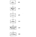
ここで、これを行う図1の装置の動作の一例について図2を参照して説明する。
ステップ200において、被験体Sに第1信号を印加し、ステップ210において、被験体Sにおいて測定された第2信号を確定する。これは、通常、上で概説した技法を用いて達成される。したがって、処理システム102は、信号発生器117A、117Bに対し第1信号を発生させ、これは、通常、第1電極113A、113Bを介して被験体Sに印加される。同様に、第2信号が、第2電極115A、115Bを介してセンサ118A、118Bによって検知され、第2信号の指示は処理システム102に提供される。
Here, an example of the operation of the apparatus of FIG. 1 that performs this will be described with reference to FIG.
In
ステップ220において、第2電極115A、115Bにおいて検知された第2信号を用いて処理システム102が不平衡を確定し、それは、一例ではコモンモード信号を表す。
In
ステップ230において、測定装置は、場合によって、不平衡、したがってコモンモード信号の大きさを低減するように、被験体Sに印加される第1信号を調整する。したがって、被験体内の信号を平衡化し、電極位置決めに対し被験体内の基準電圧の位置を中心になるように、第1電極113A、113Bのいずれか一方に印加される信号の大きさを、たとえば、相対的な信号の大きさを増大させるかまたは低減させ、かつ/または相対的な信号位相を変化させることにより調整することができる。
In
次いで、ステップ240において、測定装置は、被験体に印加される信号と、電極113A、113Bにおいて測定される電圧とを確定することができ、それによりステップ250においてインピーダンスを確定することができる。
Then, at
被験体S内の基準電圧の位置はインピーダンスによって決まるため、不平衡は、通常、印加信号の周波数に応じて変化する。したがって、一例では、不平衡を確定し、各印加周波数において印加信号を調整することが一般的である。しかしながら、これは、好ましい実施態様によって決まる可能性がある。 Since the position of the reference voltage in the subject S is determined by the impedance, the unbalance usually changes according to the frequency of the applied signal. Thus, in one example, it is common to establish an imbalance and adjust the applied signal at each applied frequency. However, this may depend on the preferred embodiment.
ここで、装置の特定の例について図3を参照してより詳細に説明する。
この例では、測定システム300は、コンピュータシステム310と別個の測定装置320とを有している。測定装置320は、コンピュータシステム310との有線通信または無線通信を可能にするインタフェース321に結合された処理システム330を有している。処理システム330を、任意に、322、323、324、325、326に示すように、種々のタイプのメモリ等の1つまたは複数の記憶装置に結合してもよい。
A specific example of the device will now be described in more detail with reference to FIG.
In this example, the
一例では、インタフェースはBluetoothスタックであるが、任意の好適なインタフェースを使用してもよい。メモリには、起動プロセスに必要な情報を格納するブートメモリ322と、デバイスシリアル番号がプログラムされ得るようにするプログラマブルシリアル番号メモリ323とがあり得る。メモリにはまた、動作中に使用される、ROM(リードオンリメモリ)324、フラッシュメモリ325およびEPROM(電気的にプログラム可能なROM)326もあり得る。これらを、当業者には理解されるように、たとえば、ソフトウェア命令を格納するため、かつ処理中にデータを格納するために用いることができる。
In one example, the interface is a Bluetooth stack, but any suitable interface may be used. The memory can include a
後により詳細に説明するように、処理システム330をセンサ118A、118Bおよび信号発生器117A、117Bに結合するために、複数のアナログ・デジタル変換器(ADC)327A、327B、328A、328Bとデジタル・アナログ変換器(DAC)329A、329Bとが設けられている。
As will be described in more detail later, a plurality of analog-to-digital converters (ADCs) 327A, 327B, 328A, 328B and digital circuits are coupled to
処理システム330の起動を制御するために、マイクロプロセッサ、マイクロコントローラまたはプログラマブルロジックデバイス等のコントローラ(図示せず)もまた設けてもよいが、より一般的には、これは処理システム330が実行するソフトウェア命令によって実行される。
A controller (not shown) such as a microprocessor, microcontroller or programmable logic device may also be provided to control the activation of the
図4に、コンピュータシステム310の一例を示す。この例では、コンピュータシステム310は、図示するように、バス404を介して互いに結合された、プロセッサ400と、メモリ401と、キーボードおよびディスプレイ等の入出力デバイス402と、外部インタフェース403とを有している。外部インタフェース403を用いて、コンピュータシステムは、必要に応じて、有線接続または無線接続を介して測定装置320と通信することができ、したがって、これは、ネットワークインタフェースカード、Bluetoothスタック等の形態であってもよい。
FIG. 4 shows an example of the
使用時、コンピュータシステム310を用いて測定装置320の動作を制御することができるが、これを、別法として、測定装置300に設けられた別個のインタフェースによって達成してもよい。さらに、コンピュータシステムを用いて、インピーダンス測定値の解析の少なくとも一部を行うことができる。
In use, the
したがって、コンピュータシステム310を、要求されたタスクが実行されるのを可能にする適当なアプリケーションソフトウェアを実装している、好適にプログラムされたPC、インターネット端末、ラップトップ、ハンドヘルドPC、スマートフォン、PDA、サーバ等、任意の好適な処理システムから形成してもよい。
Thus, a suitably programmed PC, Internet terminal, laptop, handheld PC, smartphone, PDA, which implements the
対照的に、処理システム330は、通常、特定の処理タスクを実行し、それによりコンピュータシステム310に対する処理要件を低減する。したがって、処理システムは、通常、信号発生器117A、117Bを制御する制御信号が生成されるようにする命令とともに、瞬間インピーダンス値を確定する処理を実行する。
In contrast,
一例では、処理システム330は、フィールドプログラマブルゲートアレイ(FPGA)等のカスタムハードウェア等から形成されるが、磁気論理モジュール等、任意の好適な処理モジュールを用いてもよい。
In one example, the
一例では、処理システム330はプログラマブルハードウェアを含み、その動作は、組込みソフトウェア命令の形態の命令を用いて制御される。プログラマブルハードウェアの使用により、被験体Sに種々の信号を印加することができ、かつ測定装置320によって種々の解析を行うことができる。したがって、たとえば、種々の周波数で逐次印加される信号を使用するのに比較して、同時に複数の周波数でインピーダンスを解析するように信号が用いられる場合、種々の組込みソフトウェアが利用される。
In one example, the
使用される組込みソフトウェア命令を、コンピュータシステム310からダウンロードすることができる。別法として、使用される命令を、測定装置320に設けられる入力デバイスを使用するかまたはコンピュータシステム310を使用することによって選択することができるように、命令をフラッシュメモリ325等のメモリに格納することができる。その結果、処理システム330によって実装される組込みソフトウェア等の命令を、コンピュータシステム310を用いて、制御することができ、それにより、処理システム330の動作が変更される。
Embedded software instructions used can be downloaded from the
さらに、コンピュータシステム310は、処理システム330によって確定されたインピーダンスを解析するように動作することができ、それにより生物学的パラメータを確定することができる。
Further, the
単一処理システムを用いる別の配置を用いてもよいが、コンピュータシステム310と処理システム330との間で処理を分割することにより、いくつかの利点を提供することができる。
Although other arrangements using a single processing system may be used, dividing the processing between
第1に、処理システム330を使用することにより、適当な組込みソフトウェアを使用することによって、カスタムハードウェア構成を適合させることができる。これにより、単一測定装置を使用して、種々のタイプの解析を行うことができる。
First, by using the
第2に、これにより、コンピュータシステム310に対する処理要件が大幅に低減する。これにより、コンピュータシステム310を比較的簡単なソフトウェアを用いて実装することができ、一方で、測定装置がインピーダンスの解釈を提供するために十分な解析を行うことが依然として可能である。これには、たとえば、相対的な液面、身体組成パラメータ、「ベッセル」プロットまたは他の指標等の情報を表示することとともに、心臓機能、リンパ浮腫、浮腫等の有無または程度に関連するパラメータを確定するためにインピーダンス値を使用することがあり得る。
Second, this greatly reduces the processing requirements for the
第3に、これにより、測定装置320を更新することができる。したがって、たとえば、改良された解析アルゴリズムが作成されるか、または特定のインピーダンス測定タイプに対して改良された電流シーケンスが確定された場合、フラッシュメモリ325または外部インタフェース321を介して新たな組込みソフトウェアをダウンロードすることにより、測定装置を更新することができる。
Third, this allows the
使用時、処理システム330は、駆動電極113A、113Bを介して印加される電圧駆動信号VDA、VDBを示すデジタル制御信号を生成し、それらは、DAC329によってアナログ制御信号に変換される。アナログ制御信号は信号発生器117に転送され、それにより、信号発生器117A、117Bの各々によって電圧駆動信号VDA、VDBが生成される。
In use, the
電圧駆動信号VDA、VDBによって誘導される検知電流信号ISA、ISBを表すアナログ信号が、信号発生器117A、117Bから受け取られ、ADC328A、328Bによってデジタル化される。同様に、センサ118A、118Bからの、第2電極115A、115Bにおいて測定される検知電圧VSA、VSBを表すアナログ信号が受け取られ、ADC327A、327Bによってデジタル化される。そして、デジタル信号を、予備解析のために処理システム330に戻すことができる。
Analog signals representing sense current signals I SA , I SB induced by voltage drive signals V DA , V DB are received from
この例では、ADC327、328およびDAC329のそれぞれのセットが、参照数字接尾辞A、Bによってそれぞれ示される2つのチャネルの各々に対して使用される。これにより、信号発生器117A、117Bの各々を独立して制御することができ、かつセンサ118A、118Bを用いて、電極115A、115Bから別個に信号を検出することができる。したがって、これは、2チャネル装置を表し、各チャネルは参照表示A、Bによって示されている。同様に、電圧駆動信号VD、検知電流信号ISおよび検知電圧信号VSもまた、それぞれのチャネルを表す接尾辞A、Bによって識別することができることが理解されよう。
In this example, a respective set of ADCs 327, 328 and DAC 329 is used for each of the two channels indicated by reference numeral suffixes A, B, respectively. Thereby, each of
実際には、好ましい実施態様に応じて、任意の数の好適なチャネルを使用することができる。したがって、たとえば、4つの駆動電極および4つの検知電極が設けられ、それぞれの検知電極および駆動電極の対113、115が各四肢に結合される、4チャネル配置を用いることが望ましい場合もある。この場合、8つのADC327、328と4つのDAC329の配置を用いることができ、そのため各チャネルはそれぞれのADC327、328およびDAC329を有することが理解されよう。別法として、当業者には理解されるように、ADC327、328およびDAC329の2チャネル配置を4チャネル電極配置に選択的に結合する多重化システムを含めることによる等、他の配置を使用してもよい。
In practice, any number of suitable channels can be used, depending on the preferred embodiment. Thus, for example, it may be desirable to use a four-channel arrangement in which four drive electrodes and four sense electrodes are provided and each sense and drive
肩部、臀部または種々の腹部位置における電圧の直接測定を可能にするため等、被験体の他の位置において追加の測定を行うために、さらなるチャネルを提供してもよい。
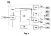
ここで、図5を参照して処理システム330によって実装される機能の一例について説明する。この例では、処理システム330は、適当なソフトウェア制御を用いて機能を実装するが、任意の好適なメカニズムを用いてもよい。
Additional channels may be provided to make additional measurements at other locations in the subject, such as to allow direct measurement of voltage at the shoulder, hip or various abdominal locations.
Here, an example of functions implemented by the
この例では、処理システム330は、タイミングおよび制御モジュール500、メッセージモジュール501、解析モジュール502、正弦波ルックアップテーブル(LUT)503、504、電流モジュール505および電圧モジュール506を有している。
In this example, the
使用時、処理システム330は、外部インタフェース321を介して、被験体Sに印加される信号の周波数および振幅を表す情報をコンピュータシステム310から受け取る。タイミングおよび制御モジュール500は、この情報を用いてLUT503、504にアクセスし、それにより、指定された周波数および振幅に基づいて、デジタル正弦派信号が生成される。デジタル制御信号はDAC329A、329Bに転送され、それにより、電圧駆動信号VDA、VDBを示すアナログ制御信号が生成される。
In use, the
測定されたアナログ電圧信号VSA、VSBおよび電流信号ISA、ISBは、ADC327、328によってデジタル化され、電流モジュール505および電圧モジュール506に提供される。これにより、処理システム330は、電流モジュール505に2つの電流信号ISA、ISBを用いて被験体を通る総電流フローを確定させることにより、電流フローを確定することができ、この指示は解析モジュール502に提供される。通常、差動電圧増幅器等の形態である電圧モジュール506は、差動電圧を確定するように動作し、それもまた解析モジュール502に転送され、解析モジュールは、電流信号および差動電圧信号を用いてインピーダンス値を確定することができる。
The measured analog voltage signals V SA , V SB and current signals I SA , I SB are digitized by ADCs 327, 328 and provided to
これに加えて、電圧モジュール506は、コモンモード信号を確定し、それはタイミングおよび制御モジュール500に戻される。これにより、タイミングおよび制御モジュール500は、被験体Sにおいて検知された電圧におけるいかなる不平衡も確定することができ、それは、上述したように、電極に対し基準電圧が被験体S内で中心に配置されていないことを示す。
In addition to this, the
不平衡が許容できない程度である場合、タイミングおよび制御モジュール500は、後述するように、電圧駆動信号VDA、VDBを表す正弦波の相対的な振幅および/または位相を調整することができ、それにより、新たな差動電圧、したがってあらゆる不平衡の指示を確定することができる。
If the unbalance is unacceptable, the timing and
不平衡が許容できるものであると確定されると、タイミングおよび制御モジュール500は、解析モジュール502にこの指示を提供することができ、解析モジュール502は、位相直交抽出等の適当な解析を用いることにより、被験体を流れる電流フローおよび差動電圧信号に基づき、測定されたインピーダンスに対して比および位相差を確定することができる。そして、比および位相を、メッセージモジュール510に転送することができ、それにより、測定インピーダンスの指示を、インタフェース321を介してコンピュータシステム310に提供することができる。
Once it is determined that the unbalance is acceptable, the timing and
処理システム330はまた、信号レベル障害検出モジュール508を実装してもよい。これは、被験体に印加される信号の大きさを監視することにより、これらが許容可能な閾値レベル内にあるか否かを確定する。許容可能な閾値レベル内にない場合、障害検出モジュール508は、メッセージがコンピュータシステム310に転送されるようにし、それによりプロセスを停止させることができ、または警告を発生することができる。
The
このプロセス中、生電流信号および生電圧信号を含む生成されるいかなる測定値も、メモリ322、323、324、325、326のうちの好適な1つに格納するか、または他の方法で出力してもよく、それにより、これを用いて装置動作を監視することができる。これを、診断とともに、装置の較正を行うために用いることができる。
During this process, any generated measurements including the raw current signal and the raw voltage signal are stored in a suitable one of the
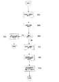
ここで、図6A〜図6Cを参照して、インピーダンス測定を行うプロセスの一例について説明する。
ステップ600において、コンピュータシステム310を用いてインピーダンス測定タイプを選択する。これによりコンピュータシステム310がトリガされ、組込みソフトウェア等の所望の命令が処理システム330によって実施される。これを、必要な組込みソフトウェアをコンピュータシステム310から処理システム330にダウンロードすることにより、または別法として処理システム330に内部メモリ等から関連する組込みソフトウェアを検索させることによる等、複数の方法によって、達成することができることが理解されよう。
Here, an example of a process for performing impedance measurement will be described with reference to FIGS. 6A to 6C.
In
ステップ610において、コンピュータシステム310または処理システム330は次の測定周波数fiを選択し、それにより、上述したように、ステップ615において、処理システム330が一連のデジタル電圧制御信号を生成することができる。ステップ620において、デジタル制御信号を、DAC329A、329Bを用いて電圧駆動信号VDA、VDBを示すアナログ制御信号に変換する。これにより、ステップ625において、アナログ制御信号を信号発生器117A、117Bの各々に提供することができ、それにより、ステップ630において、各信号発生器117A、117Bはそれぞれの電圧駆動信号VDA、VDBを生成し、それぞれの駆動電極113A、113Bを介してこれらを被験体Sに印加する。
In
ステップ635において、センサ118A、118Bに検知電極115A、115Bにおける電圧VSA、VSBを検知させることによって被験体に誘導された電圧を確定し、ステップ640において、検知した電圧信号VSA、VSBを対応するADC327A、327Bによってデジタル化する。ステップ645において、電圧駆動信号VDA、VDBの印加によってもたらされた電流信号ISA、ISBを、信号発生器117A、117Bを用いて確定する。電流信号ISA、ISBの指示を、ステップ650においてデジタル化するためにADC328A、328Bに転送する。
In
ステップ655において、デジタル化された電流信号ISA、ISBおよび電圧信号VSA、VSBを処理システム330が受け取り、それにより、ステップ660において、処理システム330は、印加電流ISの大きさを確定することができる。これを、図5の上述した機能例において電流付加モジュール505を用いて行ってもよく、それにより、ステップ665において、障害検出モジュール508が、被験体を流れる総電流フローISを閾値と比較することができる。ステップ670において、閾値を超過したと判断された場合、プロセスは、ステップ675において警告を生成して終了してもよい。
In
この状況は、たとえば、装置が不正確に機能している場合、または電極が被験体の皮膚に正しく電気的に接触していない場合等、電極の被験体への接続に問題がある場合に、発生する可能性がある。したがって、警告を用いて、装置の操作者に対し、電極接続および/または装置動作を検査するようにトリガすることができ、それによりいかなる問題も克服することができる。測定プロセスを再始動するように試みること、電極を被験体Sに再接続すること、被験体を流れる電流の大きさを低減すること等、任意の好適な形態の是正処置をとり得ることが理解されよう。 This situation can occur when there is a problem with the connection of the electrode to the subject, for example when the device is functioning incorrectly or when the electrode is not in proper electrical contact with the subject's skin. May occur. Thus, alerts can be used to trigger the operator of the device to inspect electrode connections and / or device operation, thereby overcoming any problems. Understand that any suitable form of corrective action can be taken, such as attempting to restart the measurement process, reconnecting the electrode to subject S, reducing the magnitude of the current through the subject, etc. Let's be done.
ステップ680において、処理システム330は、電極115A、115Bの各々において検知された検知電圧VSA、VSBの振幅に基づいてコモンモード電圧を確定するように動作し、これは、通常、上記機能例における電圧処理モジュール506を用いて達成される。そして、ステップ685において、コモンモード電圧またはコモンモード信号を用いて不平衡が存在するかどうか確定する。
In
ステップ690において、不平衡が許容可能であるか否かについて評価を行う。これを、コモンモード信号の振幅を閾値と比較することによる等、複数の方法のうちの任意の1つにおいて達成してもよい。閾値は、概して、事前に確定され、たとえば装置製造中または較正中に、メモリ324、325、326のうちの1つに格納される。
In
不平衡が許容可能でないと考えられた場合、ステップ695において、処理システム330は、不平衡を低減するように電圧駆動信号VDA、VDBを表すデジタル制御信号を変更する。これは、通常、処理システム330に対し、身体の中心におけるコモンモード電圧を可能な限り装置基準電圧に近いように維持するように印加電圧駆動信号VDA、VDBを調整するアルゴリズムを実施させることによって達成される。これは、概して、アルゴリズムを用いて、被験体に印加される電圧駆動信号VDA、VDBの振幅および/または位相を調整することによって達成される。この調整の特質は、不平衡の特質によって決まり、アルゴリズム例については後により詳細に説明する。
If the unbalance is deemed unacceptable, at
そして、プロセスはステップ620に戻ることができ、DAC324を用いて、変更されたデジタル制御信号をアナログ信号に変換することができ、変更された電圧駆動信号VDA、VDBを駆動電極113A、113Bに印加する。このプロセスを、許容可能な平衡が達成されるまで繰り返す。
The process can then return to step 620 and the
許容可能な平衡が達成されると、処理システム330は、ステップ700において被験体にわたって検知された差動電圧を確定するように動作する。図5に関して上述した機能例では、これを、差動電圧モジュール506を用いて達成することができる。
Once acceptable balance is achieved, the
ステップ705において、処理モジュール330は、電流信号および差動電圧信号を用いて、印加周波数fiにおいて、被験体Sのインピーダンスを表す比および位相信号を確定するように動作する。上記機能例では、これを、好ましい実施態様に応じて、解析モジュールと、位相直交解析等の何らかの形態の信号解析とを用いて行うことができる。ステップ710において、比および位相信号の指示を、さらに処理するためにコンピュータシステム310に送出する。
In
これが完了すると、プロセスはステップ610に戻り、プロセスが次の測定周波数fiで繰り返され得るようにしてもよく、または、すべての必要な周波数が完了した場合、測定プロセスは終了することができ、コンピュータシステム310は、インピーダンス測定値を解析し、任意の生物学的指標、インピーダンスパラメータ等、必要な情報を確定することができる。これが達成される方法は、行われている解析のタイプによって決まる。
When this is completed, the process returns to step 610, the process may be adapted to be repeated at the next measurement frequency f i, or, if all the necessary frequency is completed, the measurement process can be completed, The
したがって、上述したプロセスを繰り返すことによって、複数のインピーダンス測定を種々の周波数にわたって行うことができることが理解されよう。さらに、各測定に対して少なくとも1回の測定、より典型的には各測定の前に、被験体および装置のコモンモードがおよそ一致することを確実にするように検査を行うことができ、それにより測定手続きにおける不正確さが低減する。 Thus, it will be appreciated that multiple impedance measurements can be made across various frequencies by repeating the process described above. In addition, at least one measurement for each measurement, and more typically, before each measurement, a test can be performed to ensure that the common mode of the subject and the device is approximately consistent, This reduces inaccuracies in the measurement procedure.
図7Aは、駆動電極113および検知電極115の両方を組み込んだ、チャネルのうちの1つのみに対する電極システムの一例である。
電極システムは、それぞれの信号発生器117およびセンサ118が実装されている、プリント回路基板(PCB)等の第1基板750を組み込んでいる。信号発生器117およびセンサ118の概略的な機能は、図示するコンポーネントによって表されている。実際には、当業者には理解されるように、好適な配置でより多くのコンポーネントが使用される可能性があり、図示するコンポーネントは、単に、信号発生器117およびセンサ118の機能を示すように意図されている。
FIG. 7A is an example of an electrode system for only one of the channels that incorporates both the
The electrode system incorporates a
当業者には理解されるように、基板750および関連するコンポーネントを、使用中に保護するために好適なハウジング内に設けてもよい。
信号発生器117およびセンサ118は、それぞれのケーブル761、762を介して導電性パッド763、765に結合されており、それらは、第2基板760に実装されていてもよく、それぞれ第1電極113および第2電極115を形成している。使用時、ケーブル761、762は、使用後に導電性パッドを容易に交換することができるように、クリップ等を有していてもよいことが理解されよう。
As will be appreciated by those skilled in the art, the
The
理解されるように、導電性パッドは、通常、上に銀/塩化銀ゲル等の導電性ゲルがある銀パッドから形成される。これにより、被験体Sとの優れた電気的接触が確実になる。
使用時に導電性パッド763、765が所定間隔離れて配置されることを確実にするように、導電性パッドを基板760の上に実装してもよく、それは、測定の一貫性を確実にするのに役立つことができる。別法として、導電性パッド763、765を別個の使い捨て導電性パッドとして、ケーブル761、762によって第1基板750に結合して提供することができる。他の好適な配置を使用してもよい。
As will be appreciated, the conductive pad is typically formed from a silver pad with a conductive gel, such as a silver / silver chloride gel, thereon. This ensures excellent electrical contact with the subject S.
In order to ensure that the
一例では、基板760は、摩擦係数が低くかつ/または弾性の材料から形成され、かつ/または、湾曲した縁を有することにより電極が被験体に結合された時に損傷の可能性を低減する。基板760はまた、通常、導電性パッド763、765と、手首および足首等、通常の測定部位における被験体の皮膚との間の電気的接触を容易にするように配置される。これを、解剖学的構造の不規則な形状および角度と一致するように適合し、またはそのように成形された基板760を提供することによって達成することができる。
In one example, the
この例では、信号発生器117は、入力がケーブル751に結合されている増幅器A1を有している。入力はまた、抵抗器R1を介して接地等の基準電圧にも結合されている。増幅器A1の出力は、抵抗器R2を介してスイッチSWに接続されており、スイッチSWは、通常、電圧源を有効にするように用いられるCMOS(相補型金属酸化膜半導体)スイッチまたはリレーである。スイッチSWは、ケーブル752を介して処理システム330から受け取ったイネーブル信号ENを介して制御される。
In this example,
そして、スイッチSWは、直列に配置された2つの抵抗器R3、R4を介して、その後ケーブル761を介して、導電性パッド763に結合されている。第2増幅器A2には、2つの直列抵抗器のうちの第1抵抗器R3と並列な入力と、抵抗器R5を介してケーブル753に結合された出力とが設けられている。
The switch SW is coupled to the
上記から、したがって、ケーブル751、752、753が図1のリード123を形成することが理解されよう。種々の抵抗値を用いてもよいが、一例では、抵抗器の値はR1=R2=R5=50Ω、R3=R4=100Ωである。
From the above, it will therefore be appreciated that the
センサ118は、概して増幅器A3を有しており、それは、入力が抵抗器R6を介してケーブル762に接続されている。入力はまた、抵抗器R7を介して、接地等の基準電圧にも結合されている。増幅器A3の出力は、抵抗器R7を介してケーブル754に結合されている。
上記から、したがって、ケーブル754が図1のリード125を形成することが理解されよう。種々の抵抗値を用いてもよいが、一例では、抵抗器の値がR6=100Ω、R7=10MΩ、R8=50Ωである。
From the above, it will therefore be appreciated that
信号発生器117およびセンサ118に電力を供給するように電力信号+Ve、−Veを供給するために、任意の電力ケーブル755を提供することができるが、別法として、バッテリ等のオンボード電源を用いてもよい。さらに、基板750にLED757を設けることができるようにケーブル756を設けてもよい。これを、処理システム330によって制御することができ、それにより電極システムの動作状態を表示することができる。
An
ここで、信号発生器117およびセンサ118の動作についてより詳細に説明する。この説明の目的で、電圧駆動信号、電流信号および検知電圧を、概してVD、IS、VSとして示し、実際には、これらは、上記例における電圧駆動信号VDA、VDB、電流信号ISA、ISBおよび検知電圧VSA、VSBのそれぞれと等価である。
Here, the operation of the
使用時、増幅器A1は、DAC329から受け取ったアナログ電圧信号を増幅し、これを、ケーブル761を介して被験体Sに印加するように動作し、それにより、印加電圧駆動信号VDが、被験体S内に電流信号ISを駆動する。電圧駆動信号VDは、スイッチSWが閉位置にある場合にのみ印加され、したがって、電圧源を被験体Sから遮断するために、スイッチSWを開位置に配置することができる。駆動電極113と検知電極115との対が、電圧を検知するためにのみ使用されており、被験体Sに電圧駆動信号VDを印加するために使用されていない場合に、これを用いることができる。信号発生器117を駆動電極113から遮断することにより、本来、増幅器A1の低出力インピーダンスによって存在する意図されない戻り電流経路が除去され、それにより、電流が2つの選択された駆動電極113の間のみに流れるように制約される。高インピーダンス出力禁止状態を組み込んだ増幅器を用いる等、同様の効果を達成するために他の技法を用いてもよい。
In use, amplifier A 1 operates to amplify the analog voltage signal received from DAC 329 and apply it to subject S via
被験体Sに印加されている電流信号ISは、検出され、増幅器A2を用いて増幅され、増幅された電流信号ISは、ケーブル753に沿ってADC328を介して処理システム330に戻される。
Current signal I S that is applied to the subject S is detected, amplified using an amplifier A 2, the amplified current signal I S is returned to the
同様に、センサ118は、第2電極115において検出された電圧を増幅器A3に増幅させ、増幅されたアナログ検知電圧信号VSをケーブル754に沿ってADC327まで戻すことによって動作する。
Similarly, the
ケーブル751、752、753、754、755、756を、好ましい実施態様に応じて複数の異なる構成で提供してもよい。一例では、ケーブル751、752、753、754、755、756の各々は、単一リードLで提供されているが、これは必須ではなく、後により詳細に説明するように、ケーブルを複数のリードで提供することができる。
別のあり得る誤差原因は、交差電極容量結合によってもたらされる。図7Bに示すように、電極113、115および対応する接続761、762が比較的近接していることにより、駆動増幅器A1の出力と検知増幅器A3の入力との間に実効静電容量CDSがもたらされる。したがって、これは、増幅器電極A1、A3の間に寄生電流をもたらし、それにより、特に高い周波数で、測定が不正確になる可能性がある。
Another possible source of error is caused by cross-electrode capacitive coupling. As shown in FIG. 7B, by the
交差電極容量結合をキャンセルするために、図7Cに示すように、交差電極容量キャンセル回路が提供される。図7Cは、使用時の電極113、115の電気応答性をモデル化した等価回路を示している。
In order to cancel the cross-electrode capacitive coupling, a cross-electrode capacitive cancel circuit is provided as shown in FIG. 7C. FIG. 7C shows an equivalent circuit that models the electrical responsiveness of the
この例では、各電極113、115および被験体Sのインピーダンスは、それぞれの抵抗器およびコンデンサ配置によって形成されるそれぞれのインピーダンスZ113、Z115、ZSによって表されている。交差電極容量キャンセル回路770は、駆動増幅器A1の出力と検知増幅器A3の入力とに結合されており、入力が駆動増幅器A1の出力に結合されている反転増幅器A4を有している。反転増幅器の出力は、抵抗器R10およびコンデンサC10を介して検知増幅器A3の入力に直列に接続されている。
In this example, the impedance of each
この配置では、駆動増幅器A1からのいかなる信号出力も反転され、その後、検知増幅器A3の入力に印加される。抵抗器R10およびコンデンサC10に対して適当な値を選択することにより、反転信号が、実効交差電極静電容量CDSからもたらされる任意の信号の大きさと等しい大きさを有することができる。 In this arrangement, any signals output from the drive amplifier A 1 may be inverted, then, it applied to the input of the sense amplifier A 3. By selecting appropriate values for the resistors R 10 and capacitor C 10, the inverted signal may have a size equivalent to that of any signal resulting from the effective cross electrode capacitance C DS.
一例では、抵抗器R10およびコンデンサC10それぞれの抵抗および/または静電容量を、可変抵抗器またはコンデンサ等、好適な調整可能コンポーネントを使用することによって調整することができる。これにより、反転信号の大きさおよび/または位相を、実効交差電極静電容量CDSからもたらされる信号を有効にキャンセルするように制御することができる。コンポーネントの調整を、較正プロセス中に行ってもよく、それには通常、すべての寄生容量が正確に表されるように関連する電極が取り付けられた完全な電極ユニットが含まれることが理解されよう。 In one example, the resistance and / or capacitance of each of resistor R 10 and capacitor C 10 can be adjusted by using a suitable adjustable component, such as a variable resistor or capacitor. Thus, it is possible to control the magnitude and / or phase of the inverted signal, so effectively cancel the signal resulting from the effective cross electrode capacitance C DS. It will be appreciated that component adjustments may be made during the calibration process, which typically includes a complete electrode unit with associated electrodes attached so that all parasitic capacitance is accurately represented.
したがって、交差電極容量キャンセル回路770は、駆動電極113と対応する検知電極115との間に有効な負性容量を提供し、それにより、負の電流が発生し、それによって寄生電流をキャンセルする。したがって、これにより、駆動電極113と検知電極115との間のいかなる容量結合の影響も無効になる。
Therefore, the crossed electrode capacitance cancel
電極システムはまた、入力容量キャンセル回路を有していてもよく、その例を図7Dに示す。
使用時、検知電極115は環境と容量結合する可能性があり、それにより、検知増幅器A3の入力に実効入力静電容量CEIがもたらされる。実効静電容量により、検知増幅器の入力からの信号漏れが接地され、それにより、増幅器入力において得られる信号が低減する。
The electrode system may also have an input capacitance cancellation circuit, an example of which is shown in FIG. 7D.
In use, the
したがって、この例では、入力容量キャンセル回路780が提供され、それは、検知増幅器A3の正の増幅器入力を、抵抗器R11およびコンデンサC11を介して検知増幅器の出力に接続する。これは、正のフィードバックループとして作用し、それにより、増幅信号の一部を増幅器入力に戻すことができる。これは、実効入力静電容量CEIによってもたらされる増幅器入力における信号の低減をキャンセルするように作用し、したがって、増幅器入力において実効入力静電容量CEIの影響をキャンセルする有効な負性容量を提供する。この場合もまた、入力容量キャンセル回路にはチューニングが必要であり、それを、較正中に、抵抗器R11および/またはコンデンサC11の値の好適な調整によって達成することができる。
Thus, in this example, the input
簡単に上述したように、電圧信号VSおよび電流信号ISに対して別個のリード123、125が用いられる場合、リード123、125間の誘導結合により、リード123、125内にEMFが誘導されることになる可能性がある。EMFの大きさは、リード123、125間の結合の程度、したがってそれらの物理的な離隔距離によって決まり、また、電流信号ISの周波数および振幅に比例して増大する。 As briefly described above, when separate leads 123, 125 are used for the voltage signal V S and the current signal I S , EMF is induced in the leads 123, 125 by inductive coupling between the leads 123, 125. There is a possibility of becoming. The size of the EMF, the degree of coupling between the leads 123 and 125, thus determined by their physical separation, also increases in proportion to the frequency and amplitude of the current signal I S.
リード123、125内に誘導されるEMFにより、センサ118の入力に実効EMFがもたらされる。その結果、検知電圧信号VSの成分は誘導EMFに起因し、それによって、確定された電圧信号VSおよび電流信号ISが不正確になる。
The EMF induced in the leads 123, 125 provides an effective EMF at the input of the
誘導結合の影響は、リード123、125の物理的な隔離距離によって変化する。したがって、一例では、リード間の誘導結合の影響を、リードを可能な限り物理的に分離することによって低減することができる。したがって、一例では、別個の物理的に分離したリードでケーブル751、752、753、754、755、756を提供する。しかしながら、この配置の問題は、誘導結合の量が、物理的なリード形状に応じて変化し、したがって測定間で変化する可能性がある、ということである。その結果、あらゆる誘導結合の大きさが変化する可能性があり、インピーダンス測定値を解析する時にこれを考慮することが困難になる。
The influence of inductive coupling varies depending on the physical separation distance between the leads 123 and 125. Thus, in one example, the effects of inductive coupling between leads can be reduced by physically separating the leads as much as possible. Thus, in one example,
ケーブル751、752、753、754、755、756の各々に対して物理的に分離したリードを用いることに対する別法は、単一の結合されたリードLを用いるというものである。リードは、ケーブル751、752、753、754、755、756が実質的に一定の相対的な物理的構造で維持されるように形成される。一例では、リードLは、それぞれのケーブルの各々を拠り合せることにより一定の幾何学的配置を提供するように形成される。しかしながら、密接な接触を維持するようにオーバーモールドされる別個の非絶縁シールドケーブルからリードを作製する等、別の製造方法を用いることができる。
An alternative to using physically separate leads for each of
物理的形状が一定である結果として、リード123、125に沿って誘導されるいかなるEMFも実質的に一定であり、較正プロセス中にこれを考慮することができる。
したがって、測定装置320が最初に構成される時、特に、インピーダンス測定値を確定するために電圧信号VSおよび電流信号ISを解析するアルゴリズムが生成される時、これらは、誘導EMFを考慮する較正係数を含むことができる。特に、構成プロセス中、測定装置320を用いて基準インピーダンスから測定を行うことができ、結果としての計算を用いて誘導EMFの影響が確定され、それにより、後の測定値からこれを減じることができる。
As a result of the constant physical shape, any EMF induced along the leads 123, 125 is substantially constant and can be taken into account during the calibration process.
Thus, when the
リード配置の別の問題は、ここで図8に関して説明するように、それぞれのケーブル間の容量結合の問題である。この例の目的で、明確にするためにケーブル751、753、754のみを示す。
Another problem with lead placement is that of capacitive coupling between the respective cables, as described herein with respect to FIG. For purposes of this example, only
この例では、測定装置320はPCB750A、750Bに接続されることにより、電極113A、113B、115A、115Bの各々に対して接続を提供する。同様に図示するように、ケーブル751、753、754の各々には、それぞれのシールド851、853、854が設けられている。シールドは、それぞれのケーブル751、753、754間の結合を防止するのに役立つように用いられる。したがって、ケーブル751、753、754は概してシールドワイヤコアから形成されることが理解されよう。実際には、シールドケーブルは50Ω伝送線路であってもよく、それは高周波数での信号伝送歪みを最小限にし、それにより誤差を最小限にする。これに加えて、シールド851、853、854は、通常、各端部において、それぞれの接続855、856を介して接地等の基準電圧に相互接続されている。
In this example,
このようにシールドされかつ接地されたケーブルを用いることは、容量結合の影響を低減するのに役立ち、得られた測定値の不正確をさらに低減するのに役立つ。
別のあり得る問題は、異なるリードL間の誘導結合とともに、被験体とベッドとの間の容量結合の問題である。これに関して、寄生容量により、高周波数電流が身体内の意図された電流路をバイパスし、測定誤差がもたらされる。これを考慮するために、一例では、各電極システムに対するリードLを、可能な限り物理的に分離することができ、かつ/または使用時にリード長を最短にする配置で提供することができる。ここで、これを達成する配置の一例について、図9を参照して説明する。
Using a shielded and grounded cable in this way helps to reduce the effects of capacitive coupling and helps to further reduce the inaccuracy of the obtained measurements.
Another possible problem is that of capacitive coupling between the subject and the bed, as well as inductive coupling between the different leads L. In this regard, parasitic capacitance causes high frequency currents to bypass the intended current path in the body, resulting in measurement errors. To account for this, in one example, the leads L for each electrode system can be physically separated as much as possible and / or provided in an arrangement that minimizes the lead length in use. Here, an example of an arrangement for achieving this will be described with reference to FIG.
この例の目的で、測定システムは、接尾辞A、B、C、Dによって示す4つの測定チャネルを提供する。これを、図3の測定装置320の変更バージョンを用いることによって達成することができることが理解されよう。そこでは、簡単に上述したように、さらなるADC327、328およびDAC329が提供される。
For purposes of this example, the measurement system provides four measurement channels indicated by suffixes A, B, C, and D. It will be appreciated that this can be achieved by using a modified version of the
この例では、被験体Sはベッド900の上に横たわっており、腕931、932は被験体の脇に位置し、脚933、934は、測定装置320を組み込んだ支持体940の上に載っている。支持体は、いかなる形態の支持体であってもよいが、通常、成型フォーム等から成形され、測定装置320を実質的に被験体の膝の間に配置するように被験体を配置する。測定装置320は、通常、測定装置320に対する被験体の正確な位置を確実にするように、かつ測定装置320のハウジングとの摩擦または他の衝撃によってもたらされる損傷から被験体Sを保護するように、支持体内に組み込まれている。
In this example, the subject S is lying on the
4チャネル配置を提供することにより、それぞれの電極システムを被験体の四肢の各々に取り付けることができる。したがって、図示するように、各四肢931、932、933、934にはそれぞれの基板760が取り付けられており、それにより、各手首および足首に駆動電極113および検知電極115が提供される。電極113、115は、基板750に実装されたそれぞれの信号発生器およびセンサに結合され、信号発生器およびセンサは、それぞれのリードLA、LB、LC、LDを介して測定装置320に結合されている。
By providing a four channel arrangement, a respective electrode system can be attached to each of the subject's limbs. Therefore, as shown in the drawing, each
リードは、各リードLA、LB、LC、LDが測定装置320から離れて異なる方向に延在するように配置されており、それにより、リードの物理的な隔離距離が最大限になり、したがってそれらの間のいかなる誘導結合の低減にも役立つ。
The leads are arranged so that each lead LA, LB, LC, LD extends in a different direction away from the measuring
さらに、リードLA、LB、LC、LDは、測定装置320および被験体Sの両方から垂直に延在するように適合されることが好ましく、それにより、容量結合の影響がさらに低減する。
Furthermore, the leads LA, LB, LC, LD are preferably adapted to extend vertically from both the
さらに、測定装置320を被験体の膝の近くに配置することにより、測定装置320が被験体の手首と足首との間におよそ等間隔で配置される。したがって、測定装置320をベッド900の下端に向かって配置することにより、被験体Sの手首および足首に電極を配置するために必要なリードLA、LB、LC、LDの長さが短縮される一方で、実質的に等しいリード長が維持され、それは、誘導結合の影響および容量結合の影響の両方をさらに低減するのに役立つ。これに関して、いかなる誘導結合の影響から発生するEMFも、関連するリード長に比例し、それにより種々のリードに対するいかなる影響も等しくなる。同様に、電流分路をもたらす可能性があるリード(接地)と被験体Sとの間の容量結合も最小化される。
Further, by placing the measuring
上述した配置は単に例示の目的のものであり、実際には、被験体の太股の付近に(手首と足首とのおよそ中間に)測定装置320を配置する任意の好適なメカニズムを使用することができることが理解されよう。
The above-described arrangement is merely for illustrative purposes, and in practice any suitable mechanism for placing the measuring
したがって、たとえば、これには、被験体の脚に測定装置320を単に載せること、特注支持体を提供すること等が含まれ得る。
この配置において、4つの第1電極および4つの第2電極を四肢に配置することにより、種々の四肢および/または全身のインピーダンス測定を行うことができることが理解されよう。
Thus, for example, this may include simply placing the measuring
It will be appreciated that in this arrangement, various limb and / or whole body impedance measurements can be made by placing four first electrodes and four second electrodes on the limb.
図9に示す電極構成を用いて、ここで図10Aおよび図10Bを参照して説明するように、別の平衡化プロセスを行うことができる。
これらの例の目的で、被験体Sは、腕1031、1032、脚1033、1034および胴部1035を有し、測定装置300(明確にするために図示せず)は、図9に示すものと同様の多チャネル構成で提供され、駆動電極および検知電極のそれぞれの対113A、115A;113B、115B;113C、115C;113D、115Dが被験体の手首および足首に提供される。図10Aおよび図10Bには、活性電極のみを示す。
With the electrode configuration shown in FIG. 9, another equilibration process can be performed, as will now be described with reference to FIGS. 10A and 10B.
For the purposes of these examples, subject S has
各例において、駆動電極113B、113Dに駆動信号を印加する駆動電極構成が用いられ、それにより、点線1040によって示すように、信号は、腕1031、胴部1035および脚1033を通る。
In each example, a drive electrode configuration is used that applies a drive signal to drive
図10Aの例では、腕1031および脚1033に設けられている検知電極115B、115Dを用いて平衡化が行われる。対照的に、図10Bの配置では、対側肢1032、1034に設けられている検知電極115A、115Cを用いて平衡化が行われる。これにより、図10Cに示すように、平衡化プロセスに対して種々の有効電気モデルがもたらされる。有効電気モデルは、駆動電極インピーダンス113B、113D、腕1031、胴部1035および脚1033のインピーダンスをそれぞれ表すインピーダンスZ113B、Z113D、Z1031、Z1035、Z1033を含む、駆動信号にもたらされるインピーダンスを表す。
In the example of FIG. 10A, balancing is performed using the
図10Aの電極構成では、腕1031および脚1033に検知電極が設けられ、それにより、被験体内に誘導される電圧が、駆動電極113B、113Dとそれぞれの四肢1031、1033との間の点において有効に検知される。電極115B、115Dにおいて測定される検知電極を、それぞれVSBおよびVSDに示し、これらは、腕1031、胴部1035および脚1033を通る電流フローを有効に考慮する。
In the electrode configuration of FIG. 10A, detection electrodes are provided on the
平衡化を行う時、駆動信号は、VSB≒−VSDであるようにコモンモード電圧を最小化するように制御される。この構成では、実効接地基準電圧VRは、検知電圧VSB、VSDの間に電気的に中心に置かれ、それにより、基準電圧VRと各検知電圧VSB、VSDとの間の差分ΔVB、ΔVDは、およそ等しくなるΔVB≒ΔVD。したがって、これは、通常、種々の接触インピーダンスから発生する駆動電極113B、113Dに対するインピーダンスの差を考慮し、それにより、電極のうちの一方が他方の電極より大幅に高いインピーダンスを有する場合、電極の後に身体に印加される信号は、検知電極115B、115Dに関して対称のままである。
When performing the balancing, the drive signal is controlled to minimize the common mode voltage so that V SB ≈−V SD . In this configuration, the effective ground reference voltage V R is electrically centered between the sense voltages V SB and V SD , so that between the reference voltage V R and each sense voltage V SB and V SD . The differences ΔV B and ΔV D are approximately equal ΔV B ≈ΔV D. Therefore, this usually takes into account the impedance difference for the
一般に、腕の腕インピーダンスZ1031は、胴部インピーダンスZ1035および脚インピーダンスZ1033より高いため、概して、腕1031にかかる信号電圧差は、胴部1035および脚1033にかかる信号電圧差を結合したものとおよそ等しい。したがって、基準電圧VRの位置は、概して被験体の体の幾何学的中心では発生せず、被験体Sの肩部領域近くのいずれかの場所で発生する。その結果、被験体の身体中心電圧VCは、検知電圧VSB、VSDに従って平衡化することにより必ずしも最小化されず、被験体の身体中心に対応する被験体の胴部1035の中心に、著しい残留信号電圧Vがある可能性がある。したがって、身体中心電圧VC=V≠VRとなる。残留信号電圧により、被験体と、被験体が配置されているベッド等の環境との間の容量結合による電流がもたらされる。これは、インピーダンス測定値の精度に影響を与える。
Generally, the arm impedance Z 1031 of the arm is higher than the torso impedance Z 1035 and the leg impedance Z 1033 , so that the signal voltage difference applied to the
対照的に、図10Bに示す配置は、対側肢1032、1034に設けられた検知電極115A、115Cを用いて被験体の電圧を検知する。対側肢1032、1034を電流が流れていない場合、対側肢1032、1034は、それらの全長に沿って有効に同じ電圧(すなわち等電位)である。したがって、検知電極115A、115Cは、図10Cに同様に示すように胴部1035が腕1031および脚1033をつなぐ箇所において電圧を有効に測定する。
In contrast, the arrangement shown in FIG. 10B detects the voltage of the subject using the
この例では、平衡化が行われる場合、基準電圧VRは、検知電圧VSA、VSCの間に電気的に中心に配置され、それにより、基準電圧VRと各検知電圧VSA、VSCとの間の差ΔVA、ΔVCはおよそ等しくなる(ΔVA≒ΔVC)。全駆動信号VDによって誘導される電圧が胴部のみにおいて測定されるため、かつ上胴部および下胴部が同様のインピーダンスを有するため、基準電圧VRは胴部1035に沿って中間に配置される。基準電圧は一般に0Vに設定されるため、これにより、駆動電極によって誘導される、胴部1035における信号電圧の振幅が最小化し、それにより、被験体とベッドとの間の容量結合の影響が低減される。
In this example, when balancing is performed, the reference voltage V R is electrically centered between the sense voltages V SA and V SC , so that the reference voltage V R and each sense voltage V SA , V SC Differences ΔV A and ΔV C from SC are approximately equal (ΔV A ≈ΔV C ). Since the voltage induced by the total drive signal V D is measured only in the body portion, and since the Uedo portion and lower torso portions have similar impedance, the reference voltage V R disposed midway along the
したがって、図10Aの構成を用いて平衡化を行うことができることが理解されるが、これは通常、駆動電極113B、113Dの電極インピーダンスの変動しか考慮しない。これはまた、概して、被験体の胴部の全電位も低減し、したがって寄生容量の影響を低減するが、依然として、必ずしも、身体内の電圧が胴部に対して対称的に平衡化されることにはならない。したがって、一例では、図10Bに示す電極構成を用いることが好ましい。
Therefore, it is understood that balancing can be performed using the configuration of FIG. 10A, but this usually only considers variations in the electrode impedance of the
したがって、電圧駆動信号が印加されるものと同じ四肢において電圧を検知することを含む、種々の電極構成に対し、平衡化を行うことができる。しかしながら、一例では、平衡化は、第1肢、胴部および第2肢に沿って信号を通し、異なる第3肢および第4肢によって電圧信号を測定することにより、平衡化が行われる。異なる四肢で電圧を測定することにより、被験体の胴部を中心として平衡化が行われることが確実になり、それにより、被験体と環境との間の容量結合の影響が低減される結果となる。 Thus, balancing can be performed for various electrode configurations, including sensing the voltage in the same limb to which the voltage drive signal is applied. However, in one example, balancing is performed by passing signals along the first limb, torso and second limb and measuring the voltage signal with different third and fourth limbs. Measuring the voltage on different limbs ensures that equilibration occurs around the subject's torso, thereby reducing the effect of capacitive coupling between the subject and the environment. Become.
実際には、身体中心電圧が平衡化される場合であっても、常に胴部から幾分かの寄生電流があることが理解されよう。これは、胴部が物理的に比較的サイズが大きいことによる。しかしながら、身体中心電圧を平衡化するプロセスは、この誤差を最小化しようとするものであり、繰返し可能な基準点を達成することも可能にする。 It will be appreciated that in practice there will always be some parasitic current from the torso, even when the body center voltage is balanced. This is because the trunk is physically relatively large. However, the process of balancing body center voltage seeks to minimize this error and also makes it possible to achieve a repeatable reference point.
ここで、図11を参照して、さらなる測定シーケンス例についてより詳細に説明する。
この例の目的で、この場合もまた、装置は、図9に示すものと同様の多チャネル構成で提供され、駆動電極および検知電極のそれぞれの対113A、115A;113B、115B;113C、115C;113D、115Dが、被験体の手首および足首に設けられるものとする。この例では、測定プロセスが行われている時、ステップ1100において駆動電極構成を選択する。これには、たとえば、駆動電極113B、113Dを選択することが含まれ得るが、行われているインピーダンス測定のタイプに応じて、駆動電極のいかなる好適な組合せを用いてもよい。
Here, with reference to FIG. 11, the further example of a measurement sequence is demonstrated in detail.
For purposes of this example, the device is again provided in a multi-channel configuration similar to that shown in FIG. 9, and each pair of drive and
ステップ1105において、次の測定周波数を選択し、1110において、被験体に対し電圧駆動信号VDB、VDDを印加する。これにより、各検知電極115A、115B、115C、115Dにおける電圧VSA、VSB、VSC、VSDを、それぞれのセンサ118A、118B、118C、118Dによって測定することができ、電圧駆動信号VDB、VDDからもたらされる電流信号ISA、ISB、ISC、ISDを、信号発生器117A、117B、117C、117Dによって測定することができ、検知電圧信号VSA、VSB、VSC、VSDおよび電流信号ISB、ISDの指示を測定装置320に転送する。
In
そして、ステップ1115において、通常、信号の各々の指示を格納する。この情報を、複数の目的のために記録することができ、一般には、測定プロトコルに基づいて情報を選択的に記録するより、信号の各々の指示を単に記録することが最も単純である。
In
4つの検知電流信号および検知電圧信号のすべてを含むすべての信号を記録することにより、種々の目的に対し単一測定値収集プロトコルを行うことができる。そして、行われている意図された測定に応じて、記録されたデータを種々の異なる方法で逐次解析することができる。したがって、たとえば、記録されたデータを解析して、身体組成、浮腫の有無または程度等に関する情報を提供することができる。 By recording all signals, including all four sense current signals and sense voltage signals, a single measurement collection protocol can be performed for various purposes. The recorded data can then be sequentially analyzed in a variety of different ways, depending on the intended measurement being performed. Thus, for example, the recorded data can be analyzed to provide information regarding body composition, the presence or absence of edema, or the like.
ステップ1120において、測定装置320は、平衡が許容可能であるか否かを確定する。したがって、たとえば、電圧駆動信号VDB、VDDが電極113B、113Dを介して印加されている場合、測定装置320は、検知電極115A、115Cにおいて検知電圧VSA、VSCを選択し、それにより、上述した方法と同様の方法で、平衡化を評価することができる。この例では、検知電圧VSA、VSCに基づいて加算電圧VSA+VSCが確定される。加算電圧は閾値と比較され、これが閾値を下回る場合、平衡化が許容可能であることを示す。
In
平衡化が許容できない場合、ステップ1125において、被験体Sに印加される電圧駆動信号VDB、VDDを変更する。信号が調整される方法は、好ましい実施態様によって決まり得る。一例では、調整を、ステップ1110において行われる測定の結果に基づいて行う。
If the balancing is not acceptable, the voltage drive signals V DB and V DD applied to the subject S are changed in step 1125. The manner in which the signal is adjusted may depend on the preferred implementation. In one example, the adjustment is made based on the result of the measurement performed in
したがって、たとえば、検知電圧VSA、VSCを用いて、身体中心電圧VCを確定することができる。検知電流信号ISB、ISDおよび各駆動電極113B、113Dを介して印加される電圧駆動信号VDB、VDDを、身体中心電圧VCと合せて用いることにより、被験体の身体と身体中心のいずれかの側の駆動電極113B、113Dとのインピーダンスを表す上部インピーダンスZupperおよび下部インピーダンスZlowerを確定する。そして、上部インピーダンスZupperおよび下部インピーダンスZlowerを用いて、被験体を流れる好ましい電流に基づいて変更信号を確定することができる。
Therefore, for example, the body center voltage V C can be determined using the detection voltages V SA and V SC . By using the detection current signals I SB and I SD and the voltage drive signals V DB and V DD applied via the
計算例を以下より詳細に示す。この例では、身体中心電圧VCは以下に基づく。
VC=(VSA+VSC)/2 (1)
そして、以下に基づき、被験体を流れる電流を確定する。
An example calculation is shown in more detail below. In this example, the body center voltage V C is based on:
V C = (V SA + V SC ) / 2 (1)
Based on the following, the current flowing through the subject is determined.
I=(ISB−ISD)/2 (2)
ここで、
ISB=電極113Bに印加された正の電圧駆動信号VDBによってもたらされる検知電流であり、
ISD=電極113Dに印加された負の電圧駆動信号VDDによってもたらされる検知電流である。
I = (I SB −I SD ) / 2 (2)
here,
I SB = the sense current provided by the positive voltage drive signal V DB applied to
I SD = the sensing current provided by the negative voltage drive signal V DD applied to
これにより、以下のように被験体の上部分および下部分に対しインピーダンスを確定することができる。
Zupper=(VDB−VC)/I (3)
Zlower=(VDD−VC)/I (4)
ここで、
Zupper=上半身および駆動電極113Bインピーダンスであり、
Zlower=下半身および駆動電極113Dインピーダンスである。
Thereby, the impedance can be determined for the upper part and the lower part of the subject as follows.
Z upper = (V DB −V C ) / I (3)
Z lower = (V DD −V C ) / I (4)
here,
Z upper = upper body and drive
Z lower = lower body and drive
これに従って、理想的な電流値Iideal(通常、被験体の安全を保証するように90μA RMSに設定される)を用いることにより、以下の式を用いて、平衡化された測定配置をもたらす予測電圧駆動信号を確定する。 Accordingly, by using the ideal current value I ideal (usually set to 90 μA RMS to ensure subject safety), the following equation is used to predict a balanced measurement configuration: Determine the voltage drive signal.
VDB predicted=Iideal×Zupper (5)
VDD predicted=Iideal×Zlower (6)
ここで、
VDB predicted=電極113Bに対する予測理想電圧駆動信号であり、
VDD predicted=電極113Dに対する予測理想電圧駆動信号である。
V DB predicted = I ideal × Z upper (5)
V DD predicted = I ideal × Z lower (6)
here,
V DB predicted = predicted ideal voltage drive signal for
V DD predicted = the predicted ideal voltage drive signal for
したがって、この例では、被験体Sに印加される変更電圧駆動信号は、予測理想電圧VDB predited、VDD predictedであることが理解されよう。上述した計算例は、単に例示の目的のものであり、別の計算を用いてもよい。 Therefore, in this example, it will be understood that the changed voltage drive signal applied to the subject S is the predicted ideal voltage V DB predicated and V DD predicated . The calculation examples described above are for illustrative purposes only, and other calculations may be used.
一例では、計算を、信号の大きさのみに基づいて行う。これは、身体中心における電圧の大きさが、被験体と環境との間の漏れ電流に最大の影響を与えることになるためである。 In one example, the calculation is based only on the signal magnitude. This is because the magnitude of the voltage at the center of the body has the greatest effect on the leakage current between the subject and the environment.
しかしながら、大きさのみを平衡化することにより、駆動信号間に位相差をもたらす可能性があり、それにより、身体中心電圧VCが虚数成分を含むことになる可能性がある。ここで、図12A〜図12Fを参照して、この例について説明する。 However, by balancing the magnitude only, it may result in a phase difference between the drive signal, whereby the body center voltage V C may become to contain imaginary components. Here, this example will be described with reference to FIGS. 12A to 12F.
図12Bの例では、電圧は、図12Aの等価回路に基づいて示されており、そこでは、被験体は、身体中心のいずれかの側に配置された身体インピーダンスZB1、ZB2によって表されている。電極インピーダンスは身体インピーダンスの一部として表されており、図示するように駆動電圧VDB、VDDは、身体インピーダンスZB1、ZB2に直接印加されている。 In the example of FIG. 12B, the voltage is shown based on the equivalent circuit of FIG. 12A, where the subject is represented by body impedances Z B1 , Z B2 located on either side of the body center. ing. The electrode impedance is represented as a part of the body impedance, and the driving voltages V DB and V DD are directly applied to the body impedances Z B1 and Z B2 as illustrated.
図12Bに示すように、実数成分のみを含む駆動電圧VDB、VDDが印加される場合、身体インピーダンスZB1、ZB2の複素数の性質により、身体インピーダンスZB1、ZB2にかかる電圧VZB1、VZB2に位相シフトがもたらされる。その結果、身体中心電圧に対して虚数成分が存在する。この身体中心電圧に対する残留複素成分は、身体からの漏れ電流とともに、検知電圧信号に余分なコモンモード誤差をもたらす可能性があり、それにより望ましくないものとなる。 As shown in FIG. 12B, when the driving voltage V DB containing only real components, V DD is applied, the nature of the complex body impedance Z B1, Z B2, voltage according to the body impedance Z B1, Z B2 V ZB1 , V ZB2 results in a phase shift. As a result, an imaginary component exists with respect to the body center voltage. This residual complex component with respect to the body center voltage, along with leakage current from the body, can lead to extra common mode errors in the sense voltage signal, which is undesirable.
しかしながら、図12Cの例では、駆動電圧VDB、VDDが、印加信号間のそれぞれの位相差を表す虚数成分を含む場合、身体中心における電圧の位相が一致することが確実になる。これにより、実数成分および虚数成分の両方に関して身体中心電圧VCの大きさが最小化されることが確実になる。 However, in the example of FIG. 12C, when the drive voltages V DB and V DD include imaginary components representing the respective phase differences between the applied signals, it is ensured that the phases of the voltages at the body center match. This ensures that the real component and the magnitude of the body center voltage V C for both the imaginary component is minimized.
駆動電極113B、113Dに対する電極インピーダンスZ113B、Z113Dが考慮されるこのシナリオの例を、図12D〜図12Fに示す。この場合もまた、駆動電圧信号VDB、VDDに好適な位相変化を導入することにより、身体中心電圧が実数成分および虚数成分の両方に関して平衡化される結果となり得ることが分かる。
Drive
したがって、別の例では、平衡化手続きを、電圧信号を、電圧信号の大きさおよび位相の両方を表す複素数として表すことにより、かつインピーダンスの複素表現を用いることにより、行うことができる。この場合、電圧信号の大きさおよび位相の両方が平衡化されることが確実になり、それにより、最小身体中心電圧が保証される。 Thus, in another example, the balancing procedure can be performed by representing the voltage signal as a complex number that represents both the magnitude and phase of the voltage signal and by using a complex representation of impedance. In this case, it is ensured that both the magnitude and phase of the voltage signal are balanced, thereby ensuring a minimum body center voltage.
概して、印加電圧駆動信号の位相を変更する場合、半身インピーダンスは、駆動信号に対して対称位相シフトを有すると想定される。したがって、20°のインピーダンスベクトル差は、1つの駆動信号における+10°および第2駆動信号における−10°として分解される。駆動信号を可能な限り対称に維持することにより、各四肢の静電容量によって誘導されるいかなる漏れ電流も等化され、したがって半分になる。しかしながら、これは必須ではなく、位相を変更するいかなる方法を用いてもよい。 In general, when changing the phase of the applied voltage drive signal, the half-body impedance is assumed to have a symmetric phase shift with respect to the drive signal. Thus, the 20 ° impedance vector difference is resolved as + 10 ° in one drive signal and −10 ° in the second drive signal. By keeping the drive signal as symmetrical as possible, any leakage current induced by the capacitance of each limb is equalized and thus halved. However, this is not essential and any method of changing the phase may be used.
変更電圧駆動信号の確定に続き、それら変更電圧駆動信号を用いて、ステップ1110〜1120を繰返し、許容可能な平衡状況になるまで、さらなる変更電圧駆動信号を計算する。許容可能な平衡に達するために必要な反復の回数は、初期駆動信号が平衡化状況にいかに近いかによって決まることが理解されよう。 Following the determination of the changed voltage drive signal, steps 1110 to 1120 are repeated using these changed voltage drive signals to calculate additional changed voltage drive signals until an acceptable equilibrium situation is reached. It will be appreciated that the number of iterations required to reach an acceptable balance depends on how close the initial drive signal is to the balancing situation.
VDB=−VDDであるように、大きさおよび/または位相が等しい電圧駆動信号VDB、VDDを最初に印加することができるが、これにより、平衡状態に達するまで、比較的多数の異なる変更信号が試行されることになる可能性がある。電圧駆動信号の周波数が変化すると、身体インピーダンスも変化する。したがって、一例では、所与の周波数fi+1に対し、先の周波数fiに対して確定された信号VDB predicted(fi)、VDD predicted(fi)に基づいて、最初に印加される駆動信号VDB(fi+1)、VDD(fi+1)を計算する。したがって、信号VDB predicted(fi)、VDD predicted(fi)を用いて、Zupper(fi)、Zlower(fi)を計算する。Zuppser(fi)、Zlower(fi)の複素表現を用いてZupper(fi+1)、Zlower(fi+1)を確定し、それらを理想電流とともに用いて、VDB predicted(fi+1)、VDD predicted(fi+1)に対する初期値を計算する。これらの値を、ステップ1110において次の周波数fi+1に対し被験体に印加する初期信号として用いる。
Voltage drive signals V DB , V DD of equal magnitude and / or phase can be applied first such that V DB = −V DD , but this allows a relatively large number of Different change signals may be tried. When the frequency of the voltage drive signal changes, the body impedance also changes. Thus, in one example, for a given frequency f i + 1 , it is first applied based on the signals V DB predicted (f i ), V DD predicted (f i ) established for the previous frequency f i . The drive signals V DB (f i + 1 ) and V DD (f i + 1 ) are calculated. Therefore, Z upper (f i ) and Z lower (f i ) are calculated using the signals V DB predicted (f i ) and V DD predicted (f i ). Z uppser (f i), using a complex representation of the Z lower (f i) Z upper (f i + 1), to confirm the Z lower (f i + 1) , they are used in conjunction with the ideal current, V DB predicted (f i + 1 ), Calculate an initial value for V DD predicted (f i + 1 ). These values are used as initial signals to be applied to the subject at
次の周波数における平衡化アルゴリズムのための初期開始点として、先の周波数に対して確定された平衡状態を用いることにより、VC≒0の平衡状態に達するために必要な反復の数が大幅に低減する。概して、この技法を用いることにより、平衡状態を、3回以内の反復で0.1%未満の誤差まで確定することができる。 By using the balanced state established for the previous frequency as the initial starting point for the balancing algorithm at the next frequency, the number of iterations required to reach a balanced state of V C ≈0 is significantly increased. Reduce. In general, using this technique, the equilibrium state can be established to an error of less than 0.1% within 3 iterations.
したがって、先に確定された変更信号VDB predicted(fi)、VDD predicted(fi)に基づく電圧駆動信号VDB(fi+1)、VDD(fi+1)を用いる第1反復により、概して、必要な電圧の10%以内の身体中心電圧VCがもたらされる。したがって、身体中心におけるコモンモード信号電圧の大きさは、VSA、VSC間で検知される信号電圧のおよそ10%である。第2反復では、1.0%以内のVCに達するように電圧駆動信号VDB、VDDを設定することができ、第3反復では0.1%誤差に達する。 Therefore, the first iteration using the voltage drive signals V DB (f i + 1 ), V DD (f i + 1 ) based on the previously determined change signal V DB predicted (f i ), V DD predicted (f i ) Resulting in a body center voltage V C within 10% of the required voltage. Therefore, the magnitude of the common mode signal voltage at the body center is approximately 10% of the signal voltage detected between V SA and V SC . In the second iteration, the voltage drive signals V DB and V DD can be set to reach V C within 1.0%, and in the third iteration, an error of 0.1% is reached.
したがって、これにより、完全な周波数掃引に対して必要な時間を大幅に低減することができる。測定値に対する雑音の振幅を考慮することにより、測定時間をさらに最適化することができる。測定時間は、所望の精度に達するために必要な標本の数によって決まる。雑音が増大すると必要な標本も増加し、より多くの時間がかかる。したがって、測定される雑音レベルに従って標本の数が最適化される場合、測定時間を(既定標本数に対して本来必要である時間から)さらに短縮することができる。 Thus, this can significantly reduce the time required for a complete frequency sweep. The measurement time can be further optimized by taking into account the noise amplitude relative to the measurement value. The measurement time depends on the number of samples required to reach the desired accuracy. As the noise increases, more samples are needed and more time is required. Thus, if the number of samples is optimized according to the measured noise level, the measurement time can be further shortened (from the time originally required for a predetermined number of samples).
平衡が達成されると、ステップ1115で記録された測定値を用いて、ステップ1103においてインピーダンス値を計算することができる。そして、すべての周波数が完了しているか否かを評価し、完了していない場合、プロセスはステップ1105に戻り、次の測定周波数を選択する。完了している場合、すべての駆動構成が完了しているか否かを確定し、完了していない場合、プロセスはステップ1100に戻り、別の駆動構成を選択することができる。
Once equilibrium is achieved, the impedance value can be calculated in step 1103 using the measurements recorded in
完了している場合、プロセスはステップ1145で終了し、任意の画定されたインピーダンス値を、後続する解析のために処理システム310に提供することができる。
当業者は、多数の変形および変更が明らかとなることを理解するであろう。当業者に明らかとなるこうした変形および変更のすべてが、上述した広く現れている本発明の趣旨および範囲内にあるようにみなされるべきである。
If so, the process ends at
Those skilled in the art will appreciate that numerous variations and modifications will become apparent. All such variations and modifications that will be apparent to those skilled in the art should be considered to be within the spirit and scope of the invention as set forth above.
たとえば、平衡化に対し2つの異なる手法について上述した。第1例では、平衡化を、駆動電極と同じ四肢に取り付けられた検知電極を用いて行い、第2例では、平衡化に用いる検知電極を対側肢に取り付ける。一例では、検知電極および駆動電極をすべての四肢に提供し、平衡化を、駆動電極および検知電極の任意の好適な組合せを用いて同様に行うことができる。使用する電極の組合せは、行われているインピーダンス測定によって決まり得る。 For example, two different approaches to balancing have been described above. In the first example, equilibration is performed using the detection electrode attached to the same limb as the drive electrode, and in the second example, the detection electrode used for equilibration is attached to the contralateral limb. In one example, sense and drive electrodes can be provided for all limbs and equilibration can be similarly performed using any suitable combination of drive and sense electrodes. The combination of electrodes used can depend on the impedance measurement being performed.
さらに、上記種々の例からの特徴を、適当な場合は、入れ替えるかまたは組み合せて用いてもよい。さらに、したがって、たとえば、誤差を最小化するために種々の技法を記載しているが、これらを、特定の実施態様に応じて、互いに独立してまたは組み合せて使用することができる。 Furthermore, features from the various examples described above may be interchanged or combined where appropriate. In addition, thus, for example, various techniques have been described to minimize errors, but these can be used independently of or in combination with each other, depending on the particular implementation.
さらに、上記例は、ヒト等の被験体Sに焦点を当てているが、上述した測定装置および技法を、限定されないが、霊長類、家畜、競走馬等の実演動物(performance animal)等を含む任意の動物で用いることができることが理解されよう。 Further, the above example focuses on a subject S such as a human, but includes the measuring devices and techniques described above, including but not limited to performance animals such as primates, farm animals, racehorses, etc. It will be appreciated that any animal can be used.
上述したプロセスを、限定されないが、浮腫、リンパ浮腫、身体組成等を含む、さまざまな症状および疾患の有無または程度を診断するために用いることができる。 The process described above can be used to diagnose the presence or extent of various symptoms and diseases, including but not limited to edema, lymphedema, body composition, and the like.
Claims (45)
a)前記被験体の手足にそれぞれ接続された複数の第1電極を介して前記被験体に第1信号が印加されるようにし、
b)前記被験体の手足にそれぞれ接続された複数の第2電極を介して前記被験体において測定された第2信号を確定し、
c)前記第2信号を閾値と比較し、
d)前記比較の結果に応じて許容できない不平衡が存在するか否かを確定し、
e)許容できない不平衡が存在する場合、
i)前記不平衡に従って、変更第1信号を確定し、
ii)前記変更第1信号が前記被験体に印加されるようにし、それにより少なくとも1つのインピーダンス測定が行われ得るようにする
処理システムを有する装置。 A device used when performing impedance measurement on a subject,
a) a first signal is applied to the subject via a plurality of first electrodes respectively connected to the subject's limbs;
b) via said subject a plurality of second electrodes respectively connected to the limbs to determine the second signal measured in said subject,
c) comparing the second signal with a threshold;
d) determine whether there is an unacceptable imbalance depending on the result of the comparison;
e ) If there is an unacceptable imbalance,
i) confirming the modified first signal according to said unbalance,
ii) an apparatus having a processing system that allows the modified first signal to be applied to the subject, thereby allowing at least one impedance measurement to be made;
a)前記第2電極の各々において検知される電圧を確定し、
b)加算電圧を確定し、
c)前記加算電圧を用いて前記不平衡を確定する、請求項1に記載の装置。 The second signal includes a voltage sensed at each second electrode, and the processing system comprises:
a) determining the voltage sensed at each of the second electrodes;
b) Confirm the addition voltage,
2. The apparatus of claim 1, wherein c) the unbalance is determined using the summed voltage.
b)前記第2信号が、前記被験体の第3肢および第4肢に結合された第2電極を介して検知され、前記第3肢および前記第4肢が前記第1肢および前記第2肢とは異なる、請求項1〜5のいずれか一項に記載の装置。 a) the first signal is applied via a first electrode coupled to the first and second limbs of the subject;
b) the second signal is sensed via a second electrode coupled to the third and fourth limbs of the subject, wherein the third and fourth limbs are the first and second limbs; limb differs from the apparatus according to any one of claims 1-5.
a)前記第1信号が第1電極を介して印加されるようにし、
b)複数の第2電極の各々において検知される第2信号を確定し、
c)前記第2電極のうちの選択されたものにおいて検知される第2信号を選択し、
d)前記選択された第2信号を用いて不平衡が存在するかどうかを確定する、請求項1〜6のいずれか一項に記載の装置。 The processing system is
a) the first signal is applied through a first electrode;
b) to confirm the second signal sensed at each of the plurality of second electrodes,
c) selecting a second signal detected at a selected one of the second electrodes;
d) using a second signal said selected to determine whether imbalance exists Apparatus according to any one of claims 1-6.
a)前記第1信号を前記被験体に印加することによってもたらされる検知電流を確定し、
b)前記被験体にかかる検知電圧を確定し、
c)前記検知電流および前記検知電圧を用いてインピーダンスパラメータを確定する
ことにより、インピーダンス測定を行う、請求項1〜8のいずれか一項に記載の装置。 The processing system is
a) determining a sensed current resulting from applying the first signal to the subject;
b) confirming the detection voltage applied to the subject;
By determining the impedance parameter using the c) the sensed current and the sensed voltage, the impedance measuring apparatus according to any one of claims 1-8.
a)前記第1信号を前記被験体に印加することによってもたらされる検知電流を確定し、
b)前記検知電流を閾値と比較し、
c)前記比較の結果に応じてインピーダンス測定プロセスを選択的に停止する、請求項1〜9のいずれか一項に記載の装置。 The processing system is
a) determining a sensed current resulting from applying the first signal to the subject;
b) comparing the sensed current with a threshold;
selectively stopping the impedance measurement process in accordance with c) of the comparison result, according to any one of claims 1-9.
a)前記第1信号を前記被験体に印加することによってもたらされる検知電流を確定し、
b)前記変更第1信号を確定するために前記検知電流を用いる、請求項1〜10のいずれか一項に記載の装置。 The processing system is
a) determining a sensed current resulting from applying the first signal to the subject;
b) using said sense current to determine the changes first signal, apparatus according to any one of claims 1-10.
a)第1信号が第1周波数で前記被験体に印加されるようにし、
b)前記被験体において測定される第2信号を確定し、
c)前記第2信号を閾値と比較し、
d)前記比較の結果に応じて許容できない不平衡が存在するか否かを確定し、
e)許容できない不平衡が存在しない場合、少なくとも前記第2信号を用いて少なくとも1つのインピーダンス値を確定し、
f)許容できない不平衡が存在する場合、
i)前記不平衡に従って変更第1信号を確定し、
ii)前記変更第1信号が前記被験体に印加されるようにし、
iii)前記被験体において測定される変更第2信号を確定し、
iv)前記変更第2信号に対してステップc)〜f)を繰り返し、
g)少なくとも1つの第2周波数に対してステップa)〜f)を繰り返す、請求項1〜11のいずれか一項に記載の装置。 The processing system is
a) causing a first signal to be applied to the subject at a first frequency;
b) to confirm the second signals to be measured in the subject,
c) comparing the second signal with a threshold;
d) determine whether there is an unacceptable imbalance depending on the result of the comparison;
e) If unacceptable imbalance exists, to confirm the at least one impedance value using at least the second signal,
f ) if there is an unacceptable imbalance,
i) confirm the changed first signal according to said unbalance;
ii) causing the modified first signal to be applied to the subject;
iii) to confirm the second signal changes to be measured in the subject,
iv) repeating steps c) ~ f) for the change second signal,
g) repeating steps a) ~ f) for at least one second frequency, apparatus according to any one of claims 1 to 11.
a)第1電極を介して、電圧駆動信号が前記被験体に印加されるようにし、
b)前記電圧駆動信号によってもたらされる検知電流信号を確定し、
c)それぞれの第2電極を介して測定される検知電圧を確定し、
d)前記検知電圧から身体中心電圧を確定し、
e)前記検知電流信号、前記電圧駆動信号および前記身体中心電圧を用いて、前記被験体に対する上部インピーダンスおよび下部インピーダンスを確定し、
f)前記上部インピーダンスおよび前記下部インピーダンスならびに理想電流信号の指示値を用いて、変更電圧駆動信号を確定する、請求項1〜12のいずれか一項に記載の装置。 The processing system is
a) a voltage drive signal is applied to the subject via the first electrode;
b) determining a sense current signal provided by the voltage drive signal;
c) determining the sensing voltage measured through each second electrode;
d) The body center voltage is determined from the detected voltage,
e) determining an upper impedance and a lower impedance for the subject using the sensed current signal, the voltage drive signal and the body center voltage;
The apparatus according to any one of claims 1 to 12 , wherein a changed voltage drive signal is determined using the upper impedance, the lower impedance, and an indication of an ideal current signal.
a)前記第1位相、
b)前記第1大きさ、
c)前記第2位相、および
d)前記第2大きさ
のうちの少なくとも1つを変更することにより、前記変更電圧駆動信号を確定する、請求項13に記載の装置。 The voltage drive signal includes a first voltage drive signal and a second voltage drive signal applied to the subject via respective first electrodes, the first voltage drive signal having a first magnitude and a first phase. The second voltage drive signal has a second magnitude and a second phase, and the processing system comprises:
a) the first phase;
b) the first size,
14. The apparatus of claim 13 , wherein the changed voltage drive signal is determined by changing at least one of c) the second phase, and d) the second magnitude.
a)前記変更電圧駆動信号が前記被験体に印加されるようにし、
b)それぞれの第2電極を介して測定される検知電圧を確定し、
c)前記検知電圧を用いて許容できない不平衡が存在するか否かを確定し、
d)許容できない不平衡が存在する場合、
i)さらなる変更電圧駆動信号を確定し、
ii)あらゆる不平衡が許容可能となるまでステップ(a)〜(d)を繰り返す、請求項13または14に記載の装置。 The processing system is
a) causing the modified voltage drive signal to be applied to the subject;
b) determining the detection voltage measured via each second electrode;
c) determine whether there is an unacceptable imbalance using the sense voltage;
d) If there is an unacceptable imbalance,
i) Confirm further change voltage drive signal,
The apparatus according to claim 13 or 14 , wherein ii) steps (a) to (d) are repeated until any imbalance is acceptable.
a)第1周波数に対し、
i)許容可能な不平衡をもたらす変更第1信号を確定するステップと、
ii)前記変更第1信号を用いてインピーダンス測定が行われるようにするステップと、
b)第2周波数に対し、
i)前記被験体に第1信号が印加されるようにするステップであって、前記第1信号が、前記第1周波数に対して確定された前記変更第1信号に基づく、ステップと、
ii)許容できない不平衡が存在するか否かを確定するステップと、
を含む、請求項16に記載の装置。 The processing system is
a) For the first frequency,
i) determining a modified first signal that results in an acceptable imbalance;
ii) allowing an impedance measurement to be performed using the modified first signal;
b) For the second frequency,
i) causing a first signal to be applied to the subject, wherein the first signal is based on the modified first signal established for the first frequency;
ii) determining whether there is an unacceptable imbalance;
The apparatus of claim 16 comprising:
a)第1周波数に対し、
i)それぞれの第1電極を介して前記被験体に第1電圧駆動信号および第2電圧駆動信号が印加されるようにするステップと、
ii)許容可能な不平衡をもたらす変更第1電圧駆動信号および変更第2電圧駆動信号を確定するステップであって、前記第1電圧駆動信号が第1大きさおよび第1位相を有し、前記第2電圧駆動信号が第2大きさおよび第2位相を有する、ステップと、
b)第2周波数に対し、
i)前記被験体に対し第1電圧駆動信号および第2電圧駆動信号が印加されるようにするステップであって、前記第1電圧駆動信号が前記第1大きさおよび前記第1位相を有し、前記第2電圧駆動信号が前記第2大きさおよび前記第2位相を有する、ステップと、
ii)許容できない不平衡が存在するか否かを確定するステップと、
を含む、請求項17に記載の装置。 The processing system is
a) For the first frequency,
i) applying a first voltage drive signal and a second voltage drive signal to the subject through each first electrode;
ii) determining a modified first voltage drive signal and a modified second voltage drive signal that result in an acceptable imbalance, wherein the first voltage drive signal has a first magnitude and a first phase; The second voltage drive signal has a second magnitude and a second phase;
b) For the second frequency,
i) applying a first voltage drive signal and a second voltage drive signal to the subject, the first voltage drive signal having the first magnitude and the first phase. The second voltage drive signal has the second magnitude and the second phase; and
ii) determining whether there is an unacceptable imbalance;
The apparatus of claim 17 , comprising:
a)制御信号を生成し、
b)前記制御信号を少なくとも1つの信号発生器に転送することにより、前記第1信号が前記被験体に印加されるようにし、
c)前記少なくとも1つの信号発生器から、前記被験体に印加される前記1つまたは複数の信号の指示値を受け取り、
d)少なくとも1つのセンサから前記被験体において測定される1つまたは複数の第2信号の指示値を受け取り、
e)前記指示値の少なくとも予備処理を行うことにより、インピーダンス値が確定され得るようにする、請求項1〜18のいずれか一項に記載の装置。 The processing system is
a) generating a control signal;
b) transferring the control signal to at least one signal generator so that the first signal is applied to the subject;
c) receiving an indication value of the one or more signals applied to the subject from the at least one signal generator;
d) receiving an indication value of one or more second signals measured in the subject from at least one sensor;
By performing at least pretreatment e) the indicated value, so that the impedance value can be determined, according to any one of claims 1 to 18.
a)前記第2電極において測定される前記電圧を示す差動電圧、および
b)任意の不平衡を示すコモンモード信号
の少なくとも一方を生成する、請求項20に記載の装置。 The differential amplifier is
21. The apparatus of claim 20 , generating at least one of a) a differential voltage indicative of the voltage measured at the second electrode, and b) a common mode signal indicative of any unbalance.
a)前記処理システムから1つまたは複数の制御信号を受け取り、
b)前記制御信号を増幅し、それにより前記第1信号を生成する、請求項22に記載の装置。 Each signal generator
a) receiving one or more control signals from the processing system;
23. The apparatus of claim 22 , wherein b) amplifies the control signal, thereby generating the first signal.
a)前記第1信号を前記被験体に印加することによってもたらされる検知電流を確定し、
b)前記検知電流を前記処理システムに供給する、請求項22または23に記載の装置。 Each signal generator
a) determining a sensed current resulting from applying the first signal to the subject;
b) supplying said sensing current in said processing system, according to claim 22 or 23.
a)センサ、および
b)信号発生器
を有する、請求項1〜27のいずれか一項に記載の装置。 A plurality of electrode systems, each electrode system comprising:
28. Apparatus according to any one of claims 1 to 27 , comprising a) a sensor, and b) a signal generator.
a)信号発生器およびセンサが実装されている第1基板と、
b)少なくとも2つの導電性パッドが実装されている第2基板であって、前記導電性パッドが、使用時に前記信号発生器および前記センサを被験体に結合するための第1電極および第2電極を形成する、第2基板と、
を有する、請求項28に記載の装置。 The electrode system
a) a first board on which a signal generator and a sensor are mounted;
b) a second substrate on which at least two conductive pads are mounted, wherein the conductive pads are used to couple the signal generator and the sensor to a subject in a first electrode and a second electrode. Forming a second substrate;
30. The apparatus of claim 28 , comprising:
a)抵抗器、
b)コンデンサ、および
c)インダクタ
のうちの少なくとも1つを介して前記センサ入力に結合される、請求項31または32に記載の装置。 Inverting amplifier output is
a) resistors,
33. The apparatus of claim 31 or 32 , coupled to the sensor input via at least one of b) a capacitor, and c) an inductor.
a)抵抗器、
b)コンデンサ、および
c)インダクタ
のうちの少なくとも1つを含む、請求項36に記載の装置。 The feedback loop is
a) resistors,
40. The apparatus of claim 36 , comprising at least one of b) a capacitor, and c) an inductor.
b)測定装置を前記電極システムに接続するための複数のリードであって、各リードが、
i)前記測定装置と前記信号発生器とを接続し、前記測定装置と前記センサとを接続するための少なくとも2つの接続と、
ii)前記少なくとも2つの接続の各々に対するシールドであって、電気的に接続され、かつ前記測定装置および前記電極システムの各々において基準電圧に接続される、シールドと、
を有するリードと、
を有する、請求項1〜39のいずれか一項に記載の装置。 a) a plurality of electrode systems, each electrode system having a signal generator and a sensor;
b) Through measurement device comprising: a plurality of leads for connection to the electrode system, each lead,
i) connecting the measuring device and the signal generator, and at least two connections for connecting the measuring device and the sensor;
ii) a shield for each of the at least two connections, the shield being electrically connected and connected to a reference voltage in each of the measuring device and the electrode system;
A lead having
40. The apparatus according to any one of claims 1 to 39 , comprising:
i)第1信号を前記被験体に印加する信号発生器と、
ii)前記被験体における第2信号を検知するセンサと、
iii)前記信号発生器を前記被験体に結合する第1電極と、
iv)前記センサを前記被験体に結合する第2電極と、
を有する電極システムと、
b)インピーダンス測定を行うことができるように前記電極システムを制御する測定装置と、
c)前記測定装置を前記電極システムに接続するための少なくとも2つのリードと、
を有する、請求項40に記載の装置。 a) at least two electrode systems, each electrode system comprising:
i) a signal generator for applying a first signal to the subject;
ii) a sensor for detecting a second signal in the subject;
iii) a first electrode that couples the signal generator to the subject;
iv) a second electrode that couples the sensor to the subject;
An electrode system comprising:
b) a measuring device for controlling the electrode system so that impedance measurements can be made;
c) at least two leads for connecting the measuring device to the electrode system;
41. The apparatus of claim 40 , comprising:
i)前記測定装置から異なる方向に延在し、それによりそれらの間の誘導結合を低減し、かつ/または
ii)リード長を最小限にする
ように配置される、請求項41に記載の装置。 When the lead is in use,
i) extend in different directions from the measuring device, thereby reducing the inductive coupling therebetween, and / or ii) is positioned so as to minimize rie de length, according to claim 41 Equipment.
a)前記コンピュータシステムから受け取った命令に従って制御信号を生成し、
b)インピーダンス値を確定することができるように、測定されたインピーダンス値を示すデータを前記コンピュータシステムに提供する、請求項1〜42のいずれか一項に記載の装置。 An interface for coupling the processing system to a computer system, the processing system comprising:
a) generating a control signal according to instructions received from the computer system;
43. Apparatus according to any one of claims 1 to 42 , wherein b) providing data indicative of the measured impedance value to the computer system so that the impedance value can be determined.
a)前記被験体の手足にそれぞれ接続された複数の第1電極を介して前記被験体に第1信号が印加されるようにするステップと、
b)前記被験体の手足にそれぞれ接続された複数の第2電極を介して前記被験体において測定された第2信号を確定するステップと、
c)前記第2信号を閾値と比較し、
d)前記比較の結果に応じて許容できない不平衡が存在するか否かを確定し、
e)不平衡が存在する場合、
i)前記不平衡に従って変更第1信号を確定し、
ii)前記変更第1信号が前記被験体に印加されるようにし、それにより少なくとも1つのインピーダンス測定を行うことができるようにするステップと、
を含む方法。 A method used in performing impedance measurements on a subject, in a processing system,
a) causing a first signal to be applied to the subject via a plurality of first electrodes respectively connected to the subject's limbs;
a step b) through a plurality of second electrodes respectively connected to the limbs of the subject to determine the second signal measured in said subject,
c) comparing the second signal with a threshold;
d) determine whether there is an unacceptable imbalance depending on the result of the comparison;
e ) If an imbalance exists,
i) confirm the changed first signal according to said unbalance;
ii) allowing the modified first signal to be applied to the subject, thereby enabling at least one impedance measurement to be made;
Including methods.
Applications Claiming Priority (3)
| Application Number | Priority Date | Filing Date | Title |
|---|---|---|---|
| AU2007906049A AU2007906049A0 (en) | 2007-11-05 | Impedance determination | |
| AU2007906049 | 2007-11-05 | ||
| PCT/AU2008/001521 WO2009059351A1 (en) | 2007-11-05 | 2008-10-15 | Impedance determination |
Publications (3)
| Publication Number | Publication Date |
|---|---|
| JP2011502014A JP2011502014A (en) | 2011-01-20 |
| JP2011502014A5 JP2011502014A5 (en) | 2011-11-17 |
| JP5513396B2 true JP5513396B2 (en) | 2014-06-04 |
Family
ID=40625275
Family Applications (1)
| Application Number | Title | Priority Date | Filing Date |
|---|---|---|---|
| JP2010531375A Active JP5513396B2 (en) | 2007-11-05 | 2008-10-15 | Impedance determination method and apparatus |
Country Status (7)
| Country | Link |
|---|---|
| US (2) | US8836345B2 (en) |
| EP (1) | EP2211714B1 (en) |
| JP (1) | JP5513396B2 (en) |
| AU (1) | AU2008324750B2 (en) |
| CA (1) | CA2704061C (en) |
| ES (1) | ES2615128T3 (en) |
| WO (1) | WO2009059351A1 (en) |
Families Citing this family (38)
| Publication number | Priority date | Publication date | Assignee | Title |
|---|---|---|---|---|
| AUPQ113799A0 (en) | 1999-06-22 | 1999-07-15 | University Of Queensland, The | A method and device for measuring lymphoedema |
| EP1898784B1 (en) | 2005-07-01 | 2016-05-18 | Impedimed Limited | Method and apparatus for performing impedance measurements |
| WO2007002991A1 (en) | 2005-07-01 | 2007-01-11 | Impedimed Limited | Monitoring system |
| ES2476999T3 (en) | 2005-10-11 | 2014-07-15 | Impedimed Limited | Hydration Status Monitoring |
| CA2670293C (en) | 2006-11-30 | 2017-01-03 | Impedimed Limited | Measurement apparatus |
| JP5419861B2 (en) | 2007-04-20 | 2014-02-19 | インぺディメッド リミテッド | Impedance measuring apparatus and method |
| AU2008207672B2 (en) | 2008-02-15 | 2013-10-31 | Impedimed Limited | Impedance Analysis |
| JP5616900B2 (en) * | 2008-11-28 | 2014-10-29 | インぺディメッド リミテッドImpedimed Limited | Impedance measurement process |
| AU2010312305B2 (en) | 2009-10-26 | 2014-01-16 | Impedimed Limited | Fluid level indicator determination |
| WO2011060497A1 (en) | 2009-11-18 | 2011-05-26 | Impedimed Limited | Signal distribution for patient-electrode measurements |
| DE102009047247A1 (en) * | 2009-11-27 | 2011-09-08 | Hahn-Schickard-Gesellschaft für angewandte Forschung e.V. | A load condition determiner, load assembly, power supply circuit, and method for determining a load condition of an electrical power source |
| JP4947173B2 (en) * | 2010-03-16 | 2012-06-06 | 横河電機株式会社 | AC impedance measuring device |
| KR101697342B1 (en) * | 2010-05-04 | 2017-01-17 | 삼성전자 주식회사 | Method and apparatus for performing calibration in touch sensing system and touch sensing system applying the same |
| CA2802505A1 (en) | 2010-07-02 | 2012-01-05 | Impedimed Limited | Tissue indicator determination |
| CA2863041A1 (en) | 2011-02-03 | 2012-08-09 | Impedimed Limited | Tissue mass indicator determination |
| EP2696099B1 (en) * | 2011-04-05 | 2016-12-28 | Bridgestone Corporation | Vehicle vibration reduction system |
| AU2012351988B2 (en) | 2011-12-14 | 2017-05-04 | Impedimed Limited | Devices, systems and methods for determining the relative spatial change in subsurface resistivities across frequencies in tissue |
| JP6420246B2 (en) * | 2013-09-30 | 2018-11-14 | 学校法人北里研究所 | Length measuring device, length measuring method, program, shape estimating device, and body fat percentage measuring device |
| ES2535280B1 (en) * | 2013-11-05 | 2016-03-15 | Universidad De Extremadura | Method, device and food quality control system |
| US9717428B2 (en) * | 2014-02-07 | 2017-08-01 | Medtronic, Inc. | Devices and methods for sensing physiological signals during stimulation therapy |
| KR101648383B1 (en) * | 2014-09-19 | 2016-08-24 | 한국과학기술연구원 | Bio-sensor having interdigitated microelectrode |
| KR20160035853A (en) * | 2014-09-24 | 2016-04-01 | 삼성전자주식회사 | Apparatus for measuring a body-impedance and the system including the same |
| WO2016073654A2 (en) * | 2014-11-04 | 2016-05-12 | Aliphcom | Strap band for a wearable device |
| US10004408B2 (en) | 2014-12-03 | 2018-06-26 | Rethink Medical, Inc. | Methods and systems for detecting physiology for monitoring cardiac health |
| US10555686B1 (en) | 2015-07-01 | 2020-02-11 | Richard C. Kimoto | Removing parasitic effects from body impedance measurements with wrist-worn and/or other devices |
| JP6813563B2 (en) | 2015-07-16 | 2021-01-13 | インペディメッド・リミテッド | Determining fluid level |
| JP6878449B2 (en) | 2015-11-10 | 2021-05-26 | インペディメッド・リミテッド | Impedance measurement system |
| KR20170061752A (en) * | 2015-11-26 | 2017-06-07 | 삼성전자주식회사 | Electronic device analyzing bio-electrical impedance by means of calribrated current |
| JP2019509153A (en) | 2016-02-16 | 2019-04-04 | インペディメッド・リミテッド | Heart failure indicator |
| AU2017220381B2 (en) | 2016-02-16 | 2022-01-20 | Impedimed Limited | Body state classification |
| US10085639B2 (en) * | 2016-03-24 | 2018-10-02 | Qualcomm Incorporated | Tracking contact quality to vital signs measurement sensors |
| JP7120994B2 (en) | 2016-08-26 | 2022-08-17 | インペディメッド・リミテッド | Subject data management system |
| WO2018094159A1 (en) * | 2016-11-17 | 2018-05-24 | Bovie Medical Corporation | Electrosurgical apparatus with dynamic leakage current compensation and dynamic rf modulation |
| KR20180095358A (en) * | 2017-02-17 | 2018-08-27 | 삼성전자주식회사 | Electronic device and body composition analysing method |
| US11484267B2 (en) * | 2018-09-11 | 2022-11-01 | Apple Inc. | Contact detection for physiological sensor |
| JP7410937B2 (en) | 2018-09-27 | 2024-01-10 | インペディメッド・リミテッド | Evaluation of impedance measurements |
| IT201900016184A1 (en) * | 2019-09-12 | 2021-03-12 | Innuvatech S R L | MULTIFREQUENCY BIOIMPEDENZIOMETER |
| CN112089418B (en) * | 2020-09-25 | 2023-08-18 | 重庆大学 | Thoracic cavity electrical impedance detection method based on human tissue conductivity frequency conversion amplitude modulation method |
Family Cites Families (259)
| Publication number | Priority date | Publication date | Assignee | Title |
|---|---|---|---|---|
| FR1344459A (en) * | 1962-10-18 | 1963-11-29 | Method and apparatus for the electrical study of living organisms | |
| US4314563A (en) * | 1970-09-24 | 1982-02-09 | The United States Of America As Represented By The Administrator Of The Veterans Administration | Apparatus for measuring relative changes in blood volume in a portion of an animal body to detect a venous occlusion |
| US3871359A (en) * | 1973-06-25 | 1975-03-18 | Interscience Technology Corp | Impedance measuring system |
| US3851641A (en) | 1973-11-29 | 1974-12-03 | J Toole | Method and apparatus for determining internal impedance of animal body part |
| US3996924A (en) * | 1974-06-19 | 1976-12-14 | Wheeler H Brownell | Occlusive impedance phlebograph and method therefor |
| US4008712A (en) * | 1975-11-14 | 1977-02-22 | J. M. Richards Laboratories | Method for monitoring body characteristics |
| US4034854A (en) | 1976-07-16 | 1977-07-12 | M I Systems, Inc. | Electrode package |
| US4184486A (en) * | 1977-08-11 | 1980-01-22 | Radelkis Elektrokemiai Muszergyarto Szovetkezet | Diagnostic method and sensor device for detecting lesions in body tissues |
| IL53286A (en) | 1977-11-02 | 1980-01-31 | Yeda Res & Dev | Apparatus and method for detection of tumors in tissue |
| US4458694A (en) | 1977-11-02 | 1984-07-10 | Yeda Research & Development Co., Ltd. | Apparatus and method for detection of tumors in tissue |
| DE2912349A1 (en) | 1979-03-29 | 1980-10-16 | Liebisch Geb | Detector system for human skin moisture content - has scanning head with two contact electrodes attached to skin under specified pressure |
| US4365634A (en) | 1979-12-06 | 1982-12-28 | C. R. Bard, Inc. | Medical electrode construction |
| US4353372A (en) | 1980-02-11 | 1982-10-12 | Bunker Ramo Corporation | Medical cable set and electrode therefor |
| FR2486386A1 (en) | 1980-07-09 | 1982-01-15 | Argamakoff Alexis | Thermographic and impedance measurer for cancer scanning - has single electrode or matrix supplying temp. and impedance signals |
| US4407300A (en) | 1980-07-14 | 1983-10-04 | Davis Robert E | Potentiometric diagnosis of cancer in vivo |
| JPS5772627A (en) | 1980-10-21 | 1982-05-07 | Tokyo Shibaura Electric Co | Apparatus for detecting abnormal cell |
| US4942880A (en) | 1981-01-28 | 1990-07-24 | Ceske Vysoke Uceni Technicke V Praze | Method for non-invasive electric diagnosis and therapy in hemodialysis and general medicine |
| US4407288B1 (en) | 1981-02-18 | 2000-09-19 | Mieczyslaw Mirowski | Implantable heart stimulator and stimulation method |
| IL62861A (en) | 1981-05-13 | 1988-01-31 | Yeda Res & Dev | Method and apparatus for carrying out electric tomography |
| CA1196691A (en) | 1982-01-12 | 1985-11-12 | Bradley Fry | Reconstruction system and methods for impedance imaging |
| SE455043B (en) | 1982-04-22 | 1988-06-20 | Karolinska Inst | DEVICE FOR MONITORING THE LIQUID BALANCE OF THE HUMAN BODY BY MEASURING THE IMPEDANCE OF THE BODY |
| US4617939A (en) | 1982-04-30 | 1986-10-21 | The University Of Sheffield | Tomography |
| US4450527A (en) * | 1982-06-29 | 1984-05-22 | Bomed Medical Mfg. Ltd. | Noninvasive continuous cardiac output monitor |
| GB2126732B (en) | 1982-09-02 | 1986-01-15 | British Telecomm | Impedance measurement in 4-wire to 2-wire converters |
| GB2131558B (en) | 1982-11-05 | 1986-03-05 | Walter Farrer | Measuring potential difference |
| US4557271A (en) | 1983-05-11 | 1985-12-10 | Stoller Kenneth P | Method and apparatus for detecting body illness, dysfunction, disease and/or pathology |
| US4468832A (en) | 1983-06-24 | 1984-09-04 | Libman Broom Company | Refill sponge mop assembly |
| US4583549A (en) * | 1984-05-30 | 1986-04-22 | Samir Manoli | ECG electrode pad |
| US4646754A (en) * | 1985-02-19 | 1987-03-03 | Seale Joseph B | Non-invasive determination of mechanical characteristics in the body |
| US4688580A (en) | 1985-07-11 | 1987-08-25 | The Johns Hopkins University | Non-invasive electromagnetic technique for monitoring bone healing and bone fracture localization |
| US4686477A (en) | 1985-09-30 | 1987-08-11 | Mobil Oil Corporation | Multiple frequency electric excitation method and identifying complex lithologies of subsurface formations |
| US4763660A (en) | 1985-12-10 | 1988-08-16 | Cherne Industries, Inc. | Flexible and disposable electrode belt device |
| US4899758A (en) * | 1986-01-31 | 1990-02-13 | Regents Of The University Of Minnesota | Method and apparatus for monitoring and diagnosing hypertension and congestive heart failure |
| DE3775281D1 (en) | 1986-06-16 | 1992-01-30 | Siemens Ag | DEVICE FOR CONTROLLING A HEART PACER BY MEANS OF IMPEDANCE ON BODY TISSUES. |
| DE3854953D1 (en) | 1987-03-26 | 1996-03-14 | Dynamis Medizintechnik Ag | METHOD FOR SIGNAL CONTROL AND ARRANGEMENT FOR ELECTRICAL TREATMENT |
| US4832608A (en) * | 1987-05-22 | 1989-05-23 | Cherne Medical, Inc. | Electrode belt adapter |
| CN1024161C (en) * | 1987-09-05 | 1994-04-13 | 哈尔滨工业大学 | Intellectual faculties type free respiration resistant tachogram picturing instrument |
| US4911175A (en) * | 1987-09-17 | 1990-03-27 | Diana Twyman | Method for measuring total body cell mass and total extracellular mass by bioelectrical resistance and reactance |
| US4928690A (en) | 1988-04-25 | 1990-05-29 | Lifecor, Inc. | Portable device for sensing cardiac function and automatically delivering electrical therapy |
| US5078134A (en) * | 1988-04-25 | 1992-01-07 | Lifecor, Inc. | Portable device for sensing cardiac function and automatically delivering electrical therapy |
| US4895163A (en) * | 1988-05-24 | 1990-01-23 | Bio Analogics, Inc. | System for body impedance data acquisition |
| US4951682A (en) | 1988-06-22 | 1990-08-28 | The Cleveland Clinic Foundation | Continuous cardiac output by impedance measurements in the heart |
| DE3821575A1 (en) | 1988-06-25 | 1989-12-28 | Philips Patentverwaltung | ARRANGEMENT FOR APPROXIMATELY DETERMINING THE REPLACEMENT CIRCUIT OF AN ELECTRICAL OR. ELECTRONIC COMPONENTS AT HIGH FREQUENCIES |
| US4952928A (en) | 1988-08-29 | 1990-08-28 | B. I. Incorporated | Adaptable electronic monitoring and identification system |
| US4955383A (en) | 1988-12-22 | 1990-09-11 | Biofield Corporation | Discriminant function analysis method and apparatus for disease diagnosis and screening |
| US5511553A (en) * | 1989-02-15 | 1996-04-30 | Segalowitz; Jacob | Device-system and method for monitoring multiple physiological parameters (MMPP) continuously and simultaneously |
| US4981141A (en) * | 1989-02-15 | 1991-01-01 | Jacob Segalowitz | Wireless electrocardiographic monitoring system |
| US4905705A (en) * | 1989-03-03 | 1990-03-06 | Research Triangle Institute | Impedance cardiometer |
| IL91193A (en) | 1989-08-02 | 1996-01-19 | Yeda Res & Dev | Tumor detection system |
| GB9013177D0 (en) * | 1990-06-13 | 1990-08-01 | Brown Brian H | Real-time imaging, etc. |
| US5063937A (en) | 1990-09-12 | 1991-11-12 | Wright State University | Multiple frequency bio-impedance measurement system |
| US5199432A (en) * | 1990-10-30 | 1993-04-06 | American Home Products Corporation | Fetal electrode product for use in monitoring fetal heart rate |
| DE4100568A1 (en) | 1991-01-11 | 1992-07-16 | Fehling Guido | DEVICE FOR MONITORING A PATIENT FOR REPELLATION REACTIONS OF AN IMPLANTED ORGAN |
| US5280429A (en) * | 1991-04-30 | 1994-01-18 | Xitron Technologies | Method and apparatus for displaying multi-frequency bio-impedance |
| US5197479A (en) * | 1991-05-13 | 1993-03-30 | Mortara Instrument | Automatic electrode channel impedance measurement system for egg monitor |
| US5544662A (en) | 1991-07-09 | 1996-08-13 | Rensselaer Polytechnic Institute | High-speed electric tomography |
| US5588429A (en) | 1991-07-09 | 1996-12-31 | Rensselaer Polytechnic Institute | Process for producing optimal current patterns for electrical impedance tomography |
| GB9116215D0 (en) | 1991-07-26 | 1991-09-11 | Nat Res Dev | Electrical impedance tomography |
| US5309917A (en) * | 1991-09-12 | 1994-05-10 | Drexel University | System and method of impedance cardiography and heartbeat determination |
| GB2260416B (en) | 1991-10-10 | 1995-07-26 | Smiths Industries Plc | Resistance monitors |
| US5305192A (en) * | 1991-11-01 | 1994-04-19 | Linear Technology Corporation | Switching regulator circuit using magnetic flux-sensing |
| US5415164A (en) * | 1991-11-04 | 1995-05-16 | Biofield Corp. | Apparatus and method for screening and diagnosing trauma or disease in body tissues |
| US5282840A (en) | 1992-03-26 | 1994-02-01 | Medtronic, Inc. | Multiple frequency impedance measurement system |
| IL102300A (en) | 1992-06-24 | 1996-07-23 | N I Medical Ltd | Non-invasive system for determining of the main cardiorespiratory parameters of the human body |
| US5372141A (en) | 1992-07-01 | 1994-12-13 | Body Composition Analyzers, Inc. | Body composition analyzer |
| GB9222888D0 (en) * | 1992-10-30 | 1992-12-16 | British Tech Group | Tomography |
| ZA948393B (en) | 1993-11-01 | 1995-06-26 | Polartechnics Ltd | Method and apparatus for tissue type recognition |
| WO1995024155A1 (en) | 1994-03-11 | 1995-09-14 | British Technology Group Limited | Electrical impedance tomography |
| RU2112416C1 (en) | 1994-05-10 | 1998-06-10 | Научно-исследовательский институт вычислительной техники | Method for checking of tissue or organ condition after operation and device for its realization |
| AU1328595A (en) | 1994-06-20 | 1996-01-15 | Auckland Uniservices Limited | Brain damage monitor |
| US5704355A (en) * | 1994-07-01 | 1998-01-06 | Bridges; Jack E. | Non-invasive system for breast cancer detection |
| US5505209A (en) | 1994-07-07 | 1996-04-09 | Reining International, Ltd. | Impedance cardiograph apparatus and method |
| DE69535331D1 (en) | 1994-10-24 | 2007-01-18 | Mirabel Medical Systems Ltd | DEVICE AND MANY ELEMENTS TRANSFORMERS FOR IMAGING BY IMPEDANCE MEASUREMENT |
| US6560480B1 (en) * | 1994-10-24 | 2003-05-06 | Transscan Medical Ltd. | Localization of anomalies in tissue and guidance of invasive tools based on impedance imaging |
| US5810742A (en) | 1994-10-24 | 1998-09-22 | Transcan Research & Development Co., Ltd. | Tissue characterization based on impedance images and on impedance measurements |
| US5562607A (en) | 1995-01-18 | 1996-10-08 | Alza Corporation | Electrotransport device having reusable controller power saver |
| WO1996028088A2 (en) * | 1995-03-14 | 1996-09-19 | Vnus Medical Technologies, Inc. | Venous pump efficiency test system and method |
| US5503157A (en) * | 1995-03-17 | 1996-04-02 | Sramek; Bohumir | System for detection of electrical bioimpedance signals |
| DE19514698C1 (en) | 1995-04-13 | 1996-12-12 | Siemens Ag | Procedure for taking a distance measurement |
| US5557242A (en) | 1995-05-22 | 1996-09-17 | Motorola, Inc. | Method and apparatus for dielectric absorption compensation |
| US5919142A (en) | 1995-06-22 | 1999-07-06 | Btg International Limited | Electrical impedance tomography method and apparatus |
| JP3492038B2 (en) | 1995-08-17 | 2004-02-03 | 積水化学工業株式会社 | Body fat measurement device |
| NL1001282C2 (en) | 1995-09-26 | 1997-03-28 | A J Van Liebergen Holding B V | Stroke volume determination device for a human heart. |
| US5813404A (en) | 1995-10-20 | 1998-09-29 | Aspect Medical Systems, Inc. | Electrode connector system |
| US5807272A (en) | 1995-10-31 | 1998-09-15 | Worcester Polytechnic Institute | Impedance spectroscopy system for ischemia monitoring and detection |
| GB9524968D0 (en) * | 1995-12-06 | 1996-02-07 | Brown Brian H | Impedance pneumography |
| US6011992A (en) * | 1996-05-09 | 2000-01-04 | Church Of Spirtual Technology | System for measuring and indicating changes in the resistance of a living body |
| FR2748928A1 (en) | 1996-05-23 | 1997-11-28 | Jabourian Artin Pascal | Portable electronic cardiac rhythm detector |
| JPH10185A (en) | 1996-06-17 | 1998-01-06 | Sekisui Chem Co Ltd | Diagnosing device for failure in body fluid |
| JP3636825B2 (en) * | 1996-06-25 | 2005-04-06 | 積水化学工業株式会社 | Body fat measuring device |
| JP3636826B2 (en) | 1996-07-01 | 2005-04-06 | 積水化学工業株式会社 | Bioelectrical impedance measuring device |
| JPH1014899A (en) | 1996-07-05 | 1998-01-20 | Sekisui Chem Co Ltd | Method and device for presumption of body composition |
| US5749369A (en) | 1996-08-09 | 1998-05-12 | R.S. Medical Monitoring Ltd. | Method and device for stable impedance plethysmography |
| US5732710A (en) * | 1996-08-09 | 1998-03-31 | R.S. Medical Monitoring Ltd. | Method and device for stable impedance plethysmography |
| US5759159A (en) * | 1996-09-25 | 1998-06-02 | Ormco Corporation | Method and apparatus for apical detection with complex impedance measurement |
| CA2191285A1 (en) | 1996-11-26 | 1998-05-26 | Philip Maurice Church | Electrode arrangement for electrical impedance tomography system |
| RU2127075C1 (en) * | 1996-12-11 | 1999-03-10 | Корженевский Александр Владимирович | Method for producing tomographic image of body and electrical-impedance tomographic scanner |
| US5876353A (en) | 1997-01-31 | 1999-03-02 | Medtronic, Inc. | Impedance monitor for discerning edema through evaluation of respiratory rate |
| ES2151774B1 (en) | 1997-03-06 | 2001-07-01 | Nte Sa | APPARATUS AND PROCEDURE FOR THE MEASUREMENT OF GLOBAL AND SEGMENTAL BODY VOLUMES AND COMPOSITION IN HUMAN BEINGS. |
| ES2142219B1 (en) | 1997-03-06 | 2000-11-16 | Nte Sa | PROCEDURE TO DETERMINE THE COMPOSITION AND QUALITY OF MEAT NATURAL SUBSTANCES. |
| US6248083B1 (en) * | 1997-03-25 | 2001-06-19 | Radi Medical Systems Ab | Device for pressure measurements |
| US5788643A (en) | 1997-04-22 | 1998-08-04 | Zymed Medical Instrumentation, Inc. | Process for monitoring patients with chronic congestive heart failure |
| FI972067A0 (en) * | 1997-05-14 | 1997-05-14 | Tiit Koeoebi | Apparaturer ocffaranden Foer utvaendig maetning av physiologiska parametar |
| JPH1170090A (en) | 1997-08-29 | 1999-03-16 | Sekisui Chem Co Ltd | Bioelectricity impedance measuring device |
| US6018677A (en) * | 1997-11-25 | 2000-01-25 | Tectrix Fitness Equipment, Inc. | Heart rate monitor and method |
| US6125297A (en) | 1998-02-06 | 2000-09-26 | The United States Of America As Represented By The United States National Aeronautics And Space Administration | Body fluids monitor |
| US6006125A (en) | 1998-02-12 | 1999-12-21 | Unilead International Inc. | Universal electrocardiogram sensor positioning device and method |
| US6173003B1 (en) * | 1998-03-26 | 2001-01-09 | Visteon Global Technologies, Inc. | Dither noise source with notched frequency spectrum |
| US6354996B1 (en) * | 1998-04-15 | 2002-03-12 | Braun Gmbh | Body composition analyzer with trend display |
| CA2231038C (en) | 1998-05-05 | 2005-12-13 | Leslie W. Organ | Electrical impedance method and apparatus for detecting and diagnosing diseases |
| US6122544A (en) | 1998-05-01 | 2000-09-19 | Organ; Leslie William | Electrical impedance method and apparatus for detecting and diagnosing diseases |
| US5994956A (en) * | 1998-05-06 | 1999-11-30 | Concorso; James A. | Inductive-capacitive feedback compensation for amplifier systems |
| WO2000001301A1 (en) | 1998-07-06 | 2000-01-13 | Pastor, Aleksander | Apparatus for evaluation of skin impedance variations |
| JP3778330B2 (en) | 1998-10-01 | 2006-05-24 | 株式会社デンソー | Health care equipment |
| US6845264B1 (en) * | 1998-10-08 | 2005-01-18 | Victor Skladnev | Apparatus for recognizing tissue types |
| US6228022B1 (en) * | 1998-10-28 | 2001-05-08 | Sdgi Holdings, Inc. | Methods and instruments for spinal surgery |
| JP4025438B2 (en) | 1998-11-10 | 2007-12-19 | 積水化学工業株式会社 | Body composition estimation device |
| US6142949A (en) | 1998-11-24 | 2000-11-07 | Ortivus Ab | Lead protection and identification system |
| EP1141685B1 (en) | 1999-01-05 | 2005-02-23 | Kaiku Limited | Impedance measurements of bodily matter |
| US6317628B1 (en) | 1999-01-25 | 2001-11-13 | Cardiac Pacemakers, Inc. | Cardiac rhythm management system with painless defribillation lead impedance measurement |
| US6233473B1 (en) * | 1999-02-16 | 2001-05-15 | Hologic, Inc. | Determining body composition using fan beam dual-energy x-ray absorptiometry |
| US6497659B1 (en) | 1999-04-09 | 2002-12-24 | Spacelabs Medical, Inc. | System for identifying a cable transmitting a signal from a sensor to an electronic instrument |
| AUPQ113799A0 (en) | 1999-06-22 | 1999-07-15 | University Of Queensland, The | A method and device for measuring lymphoedema |
| KR100333166B1 (en) | 1999-07-29 | 2002-04-18 | 차기철 | Useful Apparatus and Method for Analyzing Body Composition Based on Bioelectrical Impedance |
| JP3907353B2 (en) * | 1999-08-26 | 2007-04-18 | 株式会社タニタ | Bioimpedance measurement device |
| JP2001070273A (en) * | 1999-09-03 | 2001-03-21 | Tanita Corp | Method for measuring of biological electric impedance and body composition measuring device |
| JP2001187035A (en) | 1999-12-28 | 2001-07-10 | Tanita Corp | Lesion recovery degree judging device |
| JP4064028B2 (en) | 2000-01-05 | 2008-03-19 | 株式会社タニタ | Physical fatigue assessment device |
| US6292690B1 (en) | 2000-01-12 | 2001-09-18 | Measurement Specialities Inc. | Apparatus and method for measuring bioelectric impedance |
| JP2001198098A (en) * | 2000-01-21 | 2001-07-24 | Tanita Corp | Dropsy measurement method and dropsy measurement device |
| US20010025139A1 (en) | 2000-01-31 | 2001-09-27 | Pearlman Justin D. | Multivariate cardiac monitor |
| JP4454092B2 (en) | 2000-02-15 | 2010-04-21 | 大和製衡株式会社 | Body fat mass measuring device |
| GB0005247D0 (en) | 2000-03-03 | 2000-04-26 | Btg Int Ltd | Electrical impedance method for differentiating tissue types |
| US6714814B2 (en) * | 2000-03-30 | 2004-03-30 | Tanita Corporation | Bioelectrical impedance measuring apparatus |
| JP4401529B2 (en) | 2000-04-10 | 2010-01-20 | パナソニック株式会社 | Laminate voltage measuring device |
| WO2001078005A2 (en) | 2000-04-11 | 2001-10-18 | Cornell Research Foundation, Inc. | System and method for three-dimensional image rendering and analysis |
| US6441747B1 (en) | 2000-04-18 | 2002-08-27 | Motorola, Inc. | Wireless system protocol for telemetry monitoring |
| US6496721B1 (en) * | 2000-04-28 | 2002-12-17 | Cardiac Pacemakers, Inc. | Automatic input impedance balancing for electrocardiogram (ECG) sensing applications |
| JP2001321352A (en) | 2000-05-16 | 2001-11-20 | Sekisui Chem Co Ltd | Electric characteristic measuring device |
| EP1289415A4 (en) * | 2000-05-18 | 2008-12-03 | Nuvasive Inc | Tissue discrimination and applications in medical procedures |
| US6928315B1 (en) * | 2000-05-21 | 2005-08-09 | Mirabel Medical Systems Ltd. | Apparatus for impedance imaging coupled with another modality |
| IL163684A0 (en) | 2000-05-31 | 2005-12-18 | Given Imaging Ltd | Measurement of electrical characteristics of tissue |
| JP3792489B2 (en) | 2000-06-30 | 2006-07-05 | 株式会社タニタ | Bioimpedance measurement device |
| US6964140B2 (en) * | 2000-07-03 | 2005-11-15 | Walker Steven H | Structural metal member for use in a roof truss or a floor joist |
| US6569160B1 (en) * | 2000-07-07 | 2003-05-27 | Biosense, Inc. | System and method for detecting electrode-tissue contact |
| JP3699640B2 (en) * | 2000-08-01 | 2005-09-28 | 株式会社タニタ | Body water content state determination device by multi-frequency bioimpedance measurement |
| US7801598B2 (en) | 2000-08-14 | 2010-09-21 | Fresenius Medical Care Holdings, Inc. | Device and method for the determination of dry weight by continuous measurement of resistance and calculation of circumference in a body segment using segmental bioimpedance analysis |
| US7228170B2 (en) | 2000-08-14 | 2007-06-05 | Renal Research Institute, Llc | Device and method for monitoring and controlling physiologic parameters of a dialysis patient using segmental bioimpedance |
| JP4124649B2 (en) * | 2000-11-29 | 2008-07-23 | 株式会社フィジオン | Body composition measuring method and body composition measuring device |
| JP3947651B2 (en) | 2000-12-28 | 2007-07-25 | 株式会社タニタ | Postpartum support device |
| US6768921B2 (en) | 2000-12-28 | 2004-07-27 | Z-Tech (Canada) Inc. | Electrical impedance method and apparatus for detecting and diagnosing diseases |
| DE10100569A1 (en) | 2001-01-09 | 2002-07-11 | Koninkl Philips Electronics Nv | Driver circuit for display device |
| CN1471373A (en) | 2001-02-05 | 2004-01-28 | ��³��ɭ˹��˾ | Methods of determining concentration of glucose in blood |
| ITBO20010110A1 (en) | 2001-03-01 | 2002-09-01 | Tre Esse Progettazione Biomedi | PROCEDURE AND IMPLANTABLE DEVICE FOR THE INTRA-PULMONARY MEASUREMENT OF PHYSICAL PROPERTIES OF THE PULMONARY FABRIC DEPENDENT ON ITS DENSIT |
| US6631292B1 (en) | 2001-03-23 | 2003-10-07 | Rjl Systems, Inc. | Bio-electrical impedance analyzer |
| US6931605B2 (en) | 2001-03-28 | 2005-08-16 | Council Of Scientific & Industrial Research | Simulated circuit layout for low voltage, low paper and high performance type II current conveyor |
| US6511438B2 (en) | 2001-04-03 | 2003-01-28 | Osypka Medical Gmbh | Apparatus and method for determining an approximation of the stroke volume and the cardiac output of the heart |
| JP2002330938A (en) | 2001-05-10 | 2002-11-19 | Inax Corp | Toilet seat cover device with body fat meter |
| CN101401724A (en) * | 2001-06-13 | 2009-04-08 | 康普麦迪克斯有限公司 | Methods and apparatus for monitoring consciousness |
| AUPR571801A0 (en) * | 2001-06-15 | 2001-07-12 | Polartechnics Limited | Apparatus for tissue type recognition using multiple measurement techniques |
| US7044911B2 (en) * | 2001-06-29 | 2006-05-16 | Philometron, Inc. | Gateway platform for biological monitoring and delivery of therapeutic compounds |
| US6870109B1 (en) * | 2001-06-29 | 2005-03-22 | Cadwell Industries, Inc. | System and device for reducing signal interference in patient monitoring systems |
| US6625487B2 (en) | 2001-07-17 | 2003-09-23 | Koninklijke Philips Electronics N.V. | Bioelectrical impedance ECG measurement and defibrillator implementing same |
| JP3792547B2 (en) * | 2001-07-19 | 2006-07-05 | 株式会社タニタ | Biometric device |
| US6595927B2 (en) * | 2001-07-23 | 2003-07-22 | Medtronic, Inc. | Method and system for diagnosing and administering therapy of pulmonary congestion |
| US7191000B2 (en) * | 2001-07-31 | 2007-03-13 | Cardiac Pacemakers, Inc. | Cardiac rhythm management system for edema |
| US20050137480A1 (en) | 2001-10-01 | 2005-06-23 | Eckhard Alt | Remote control of implantable device through medical implant communication service band |
| US6623312B2 (en) | 2001-10-04 | 2003-09-23 | Unilead International | Precordial electrocardiogram electrode connector |
| US20050101875A1 (en) * | 2001-10-04 | 2005-05-12 | Right Corporation | Non-invasive body composition monitor, system and method |
| JP3947379B2 (en) | 2001-10-12 | 2007-07-18 | 積水化学工業株式会社 | Electrical property measuring device |
| DE10151650A1 (en) | 2001-10-17 | 2003-05-08 | Univ Eberhard Karls | Electrode arrangement for electrical stimulation of biological material and multi-electrode array for use in such |
| JP4068567B2 (en) * | 2001-12-12 | 2008-03-26 | フレゼニウス メディカル ケア ドイッチェランド ゲゼルシャフト ミット ベシュレンクテル ハフツング | Determining patient hydration |
| JP2003230547A (en) | 2002-02-12 | 2003-08-19 | Yamato Scale Co Ltd | Health managing device |
| JP3943955B2 (en) | 2002-02-25 | 2007-07-11 | 株式会社タニタ | Deep vein thrombosis determination device |
| JP3089347U (en) | 2002-04-17 | 2002-10-25 | 船井電機株式会社 | Remote control for TV with body fat measurement function |
| US6887239B2 (en) * | 2002-04-17 | 2005-05-03 | Sontra Medical Inc. | Preparation for transmission and reception of electrical signals |
| US7630759B2 (en) | 2002-05-20 | 2009-12-08 | Epi-Sci, Llc | Method and system for detecting electrophysiological changes in pre-cancerous and cancerous breast tissue and epithelium |
| US6922586B2 (en) | 2002-05-20 | 2005-07-26 | Richard J. Davies | Method and system for detecting electrophysiological changes in pre-cancerous and cancerous tissue |
| WO2004000115A1 (en) | 2002-06-19 | 2003-12-31 | Brainz Instruments Limited | Artefact removal during eeg recordings |
| CA2519331A1 (en) | 2002-06-26 | 2004-01-22 | Capamo Aps | Apparatus for the registration of weight |
| US7096061B2 (en) * | 2002-07-03 | 2006-08-22 | Tel-Aviv University Future Technology Development L.P. | Apparatus for monitoring CHF patients using bio-impedance technique |
| DE10232018B4 (en) * | 2002-07-16 | 2008-05-21 | Dräger Medical AG & Co. KG | Method and device for determining the correlation of signals of an electrical impedance tomograph |
| JP3806734B2 (en) | 2002-07-26 | 2006-08-09 | 独立行政法人農業・食品産業技術総合研究機構 | Programmable general-purpose modules and measurement systems using them |
| US20040019292A1 (en) * | 2002-07-29 | 2004-01-29 | Drinan Darrel Dean | Method and apparatus for bioelectric impedance based identification of subjects |
| US7085598B2 (en) | 2002-08-23 | 2006-08-01 | Nihon Kohden Corporation | Biological electrode and connector for the same |
| US20060125475A1 (en) | 2002-09-17 | 2006-06-15 | Sodickson Daniel K | Radio frequency impedance mapping |
| US7783345B2 (en) | 2002-10-07 | 2010-08-24 | Cnsystems Medizintechnik Gmbh | Impedance-based measuring method for hemodynamic parameters |
| AU2002951925A0 (en) | 2002-10-09 | 2002-10-24 | Queensland University Of Technology | An Impedence Cardiography Device |
| WO2004036379A2 (en) | 2002-10-17 | 2004-04-29 | The General Hospital Corporation | Arrangement and method for detecting abnormalities and inconsistencies in a body |
| US20040092801A1 (en) | 2002-11-13 | 2004-05-13 | Budimir Drakulic | System for, and method of, acquiring physiological signals of a patient |
| EP1565105A4 (en) * | 2002-11-22 | 2009-04-01 | Impedimed Ltd | Multifrequency bioimpedance determination |
| US7313434B2 (en) | 2002-11-25 | 2007-12-25 | Regents Of The University Of Minnesota | Impedance monitoring for detecting pulmonary edema and thoracic congestion |
| EP1571981A2 (en) * | 2002-11-27 | 2005-09-14 | Z-Tech (Canada) Inc. | Eliminating interface artifact errors in bioimpedance measurements |
| GB0228375D0 (en) | 2002-12-05 | 2003-01-08 | Innovation And Entpr Off Of | Wound mapping |
| EE04767B1 (en) * | 2002-12-06 | 2007-02-15 | Tallinna Tehnika�likool | Method and apparatus for measuring electrical bio-impedance |
| US20040167423A1 (en) | 2002-12-20 | 2004-08-26 | Luana Pillon | RXc graph and RXc Z-score graph methods |
| DE60309559T2 (en) | 2003-01-09 | 2007-08-23 | Ge Healthcare Finland Oy | Shielding arrangement for ECG connection wires |
| JP3907595B2 (en) | 2003-02-25 | 2007-04-18 | 株式会社タニタ | Vein extensibility evaluation index measuring device |
| WO2004082460A2 (en) | 2003-03-14 | 2004-09-30 | Shock, Llc | Methods of and apparatus for determining fluid volume presence in mammalian tissue |
| EP1517140A3 (en) | 2003-03-19 | 2005-04-06 | TF Instruments GmbH | Method and device for diagnostic investigation of biological samples |
| US7945318B2 (en) | 2003-03-20 | 2011-05-17 | Smithmarks, Inc. | Peripheral impedance plethysmography electrode and system with detection of electrode spacing |
| US8045770B2 (en) | 2003-03-24 | 2011-10-25 | Cornell Research Foundation, Inc. | System and method for three-dimensional image rendering and analysis |
| WO2004098389A2 (en) | 2003-05-02 | 2004-11-18 | Johns Hopkins University | Devices, systems and methods for bioimpendence measurement of cervical tissue and methods for diagnosis and treatment of human cervix |
| JP2004329412A (en) * | 2003-05-02 | 2004-11-25 | Tanita Corp | Body composition measuring instrument |
| EP1648297A4 (en) * | 2003-07-31 | 2009-06-10 | Dst Delta Segments Technology | Noninvasive multi-channel monitoring of hemodynamic parameters |
| EP2382920A1 (en) * | 2003-08-20 | 2011-11-02 | Philometron, Inc. | Hydration monitoring |
| WO2005027717A2 (en) | 2003-09-12 | 2005-03-31 | Renal Research Institute, Llc | Bioimpedance methods and apparatus |
| JP4600916B2 (en) * | 2003-11-07 | 2010-12-22 | 株式会社タニタ | Shielded cable and bioelectrical impedance value or biological composition information acquisition device using shielded cable |
| US20050113704A1 (en) * | 2003-11-26 | 2005-05-26 | Lawson Corey J. | Patient monitoring system that incorporates memory into patient parameter cables |
| WO2005051194A1 (en) | 2003-11-26 | 2005-06-09 | Biospace Co. Ltd | Apparatus and method for measuring segmental body fat using bioelectrical impedance |
| US7184821B2 (en) | 2003-12-03 | 2007-02-27 | Regents Of The University Of Minnesota | Monitoring thoracic fluid changes |
| KR20050072990A (en) * | 2004-01-08 | 2005-07-13 | 황인덕 | Electrical impedance measuring apparatus |
| CA2555807A1 (en) | 2004-02-12 | 2005-08-25 | Biopeak Corporation | Non-invasive method and apparatus for determining a physiological parameter |
| JP2005253840A (en) | 2004-03-15 | 2005-09-22 | Tanita Corp | Skin condition estimating device |
| US20050261743A1 (en) | 2004-05-19 | 2005-11-24 | Kroll Mark W | System and method for automated fluid monitoring |
| JP4848369B2 (en) | 2004-06-18 | 2011-12-28 | インぺディメッド リミテッド | Apparatus and method for operating edema detection |
| US8068906B2 (en) * | 2004-06-21 | 2011-11-29 | Aorora Technologies Pty Ltd | Cardiac monitoring system |
| EP1768552A4 (en) * | 2004-06-21 | 2009-06-03 | Aorora Technologies Pty Ltd | Cardiac monitoring system |
| JP4578187B2 (en) | 2004-08-31 | 2010-11-10 | 株式会社タニタ | Body composition meter with judgment function for children |
| US9820658B2 (en) * | 2006-06-30 | 2017-11-21 | Bao Q. Tran | Systems and methods for providing interoperability among healthcare devices |
| WO2006044868A1 (en) * | 2004-10-20 | 2006-04-27 | Nervonix, Inc. | An active electrode, bio-impedance based, tissue discrimination system and methods and use |
| US20060085048A1 (en) * | 2004-10-20 | 2006-04-20 | Nervonix, Inc. | Algorithms for an active electrode, bioimpedance-based tissue discrimination system |
| US7660617B2 (en) | 2004-11-13 | 2010-02-09 | The Boeing Company | Electrical impedance tomography using a virtual short measurement technique |
| US20060111652A1 (en) * | 2004-11-22 | 2006-05-25 | Mcleod Kenneth J | Method for enhancing blood and lymph flow in the extremities |
| US20080188757A1 (en) | 2005-02-21 | 2008-08-07 | Ave Eugenio Garza Sada #2501 Sur, Col. Tecnologic | Optoelectronic Device For The Detection Of Uterine Cancer, Comprising A Self-Positioning Attachment |
| US7242169B2 (en) | 2005-03-01 | 2007-07-10 | Apple Inc. | Method and apparatus for voltage compensation for parasitic impedance |
| JP4645266B2 (en) | 2005-03-30 | 2011-03-09 | オムロンヘルスケア株式会社 | Body fat measuring device |
| US20060224079A1 (en) | 2005-03-31 | 2006-10-05 | Washchuk Bohdan O | Edema monitoring system and method utilizing an implantable medical device |
| GB2426824A (en) | 2005-06-03 | 2006-12-06 | Sheffield Teaching Hospitals | Body tissue impedance measuring probe with wireless transmitter |
| GB0511323D0 (en) | 2005-06-03 | 2005-07-13 | Sheffield Teaching Hospitals | Apparatus for measuring tissue sample electrical impedance |
| GB0511289D0 (en) | 2005-06-03 | 2005-07-13 | Sheffield Teaching Hospitals | Method and probe for measuring the impedance of human or animal body tissue |
| WO2007002991A1 (en) | 2005-07-01 | 2007-01-11 | Impedimed Limited | Monitoring system |
| AU2006265762B2 (en) | 2005-07-01 | 2012-08-16 | Impedimed Limited | Pulmonary monitoring system |
| DE102005031752B4 (en) | 2005-07-07 | 2017-11-02 | Drägerwerk AG & Co. KGaA | Electroimpedance tomography device with common-mode signal suppression |
| CA2615845A1 (en) | 2005-07-20 | 2007-01-25 | Impedance Cardiology Systems, Inc. | Index determination |
| EP1754441B1 (en) * | 2005-08-17 | 2008-01-09 | Osypka Medical GmbH | Method and apparatus for digital demodulation in the measurement of electrical bioimpedance or bioadmittance |
| ES2476999T3 (en) | 2005-10-11 | 2014-07-15 | Impedimed Limited | Hydration Status Monitoring |
| US7733224B2 (en) | 2006-06-30 | 2010-06-08 | Bao Tran | Mesh network personal emergency response appliance |
| CN100423688C (en) * | 2005-10-19 | 2008-10-08 | 深圳迈瑞生物医疗电子股份有限公司 | Method and apparatus for inhibiting power frequency common-mode interference |
| US8108047B2 (en) * | 2005-11-08 | 2012-01-31 | Newlife Sciences Llc | Device and method for the treatment of pain with electrical energy |
| DE602006015105D1 (en) | 2006-03-15 | 2010-08-05 | St Jude Medical | IMPLANTABLE MEDICINE TO ASSESS A DEGREE OF LUNG SOLE OF A PATIENT |
| JP5069878B2 (en) | 2006-07-19 | 2012-11-07 | フクダ電子株式会社 | Vein inspection device |
| US20080091114A1 (en) * | 2006-10-11 | 2008-04-17 | Pacesetter, Inc. | Techniques for Correlating Thoracic Impedance with Physiological Status |
| CN101605467A (en) | 2006-11-03 | 2009-12-16 | T·F·H·发行公司 | Nutritious supplementary pharmaceutical |
| CA2670293C (en) | 2006-11-30 | 2017-01-03 | Impedimed Limited | Measurement apparatus |
| US20090318778A1 (en) | 2007-04-30 | 2009-12-24 | Clifford Dacso | Non-invasive monitoring of physiological measurements in a distributed health care environment |
| US20090105555A1 (en) * | 2007-04-30 | 2009-04-23 | Dacso Clifford C | Non-invasive monitoring of physiological measurements in a distributed health care environment |
| CA2686883C (en) | 2007-05-14 | 2016-08-23 | Impedimed Limited | Indicator |
| WO2009026588A2 (en) * | 2007-08-23 | 2009-02-26 | Bioness Inc. | System for transmitting electrical current to a bodily tissue |
| US8374688B2 (en) | 2007-09-14 | 2013-02-12 | Corventis, Inc. | System and methods for wireless body fluid monitoring |
| WO2009036313A1 (en) * | 2007-09-14 | 2009-03-19 | Corventis, Inc. | Adherent device with multiple physiological sensors |
| US20090076343A1 (en) * | 2007-09-14 | 2009-03-19 | Corventis, Inc. | Energy Management for Adherent Patient Monitor |
| WO2009036260A1 (en) * | 2007-09-14 | 2009-03-19 | Corventis, Inc. | Data collection in a multi-sensor patient monitor |
| US9204449B2 (en) * | 2008-01-22 | 2015-12-01 | Alcatel Lucent | Method of assigning an idle state access terminal to a carrier in a multiple carrier wireless communication system based on load on control channel resources |
| CA2714367A1 (en) | 2008-02-15 | 2009-08-20 | Impedimed Limited | Analysing impedance measurements |
| AU2008207672B2 (en) | 2008-02-15 | 2013-10-31 | Impedimed Limited | Impedance Analysis |
| WO2011022068A1 (en) | 2009-08-21 | 2011-02-24 | Rutkove Seward B | A hand-held device for electrical impedance myography |
| AU2010312305B2 (en) | 2009-10-26 | 2014-01-16 | Impedimed Limited | Fluid level indicator determination |
| CA2782953A1 (en) | 2009-12-21 | 2011-06-30 | Impedimed Limited | Analysing impedance measurements |
-
2008
- 2008-10-15 WO PCT/AU2008/001521 patent/WO2009059351A1/en active Application Filing
- 2008-10-15 AU AU2008324750A patent/AU2008324750B2/en active Active
- 2008-10-15 CA CA2704061A patent/CA2704061C/en not_active Expired - Fee Related
- 2008-10-15 ES ES08800155.7T patent/ES2615128T3/en active Active
- 2008-10-15 EP EP08800155.7A patent/EP2211714B1/en active Active
- 2008-10-15 JP JP2010531375A patent/JP5513396B2/en active Active
- 2008-10-15 US US12/741,368 patent/US8836345B2/en active Active
-
2014
- 2014-09-12 US US14/484,796 patent/US20150002177A1/en not_active Abandoned
Also Published As
| Publication number | Publication date |
|---|---|
| CA2704061A1 (en) | 2009-05-14 |
| AU2008324750B2 (en) | 2014-01-16 |
| WO2009059351A1 (en) | 2009-05-14 |
| US20150002177A1 (en) | 2015-01-01 |
| EP2211714B1 (en) | 2016-11-23 |
| US8836345B2 (en) | 2014-09-16 |
| ES2615128T3 (en) | 2017-06-05 |
| JP2011502014A (en) | 2011-01-20 |
| EP2211714A4 (en) | 2015-04-01 |
| CA2704061C (en) | 2017-06-20 |
| US20110025348A1 (en) | 2011-02-03 |
| AU2008324750A1 (en) | 2009-05-14 |
| EP2211714A1 (en) | 2010-08-04 |
Similar Documents
| Publication | Publication Date | Title |
|---|---|---|
| JP5513396B2 (en) | Impedance determination method and apparatus | |
| JP5400618B2 (en) | Monitoring system | |
| JP5657553B2 (en) | Devices used in performing impedance measurements, devices used in diagnosing the presence or degree of edema, and devices used in body composition analysis | |
| JP5372768B2 (en) | measuring device | |
| JP2010515492A5 (en) | ||
| JP5755234B2 (en) | Apparatus and system for patient-electrode measurement |
Legal Events
| Date | Code | Title | Description |
|---|---|---|---|
| A521 | Request for written amendment filed |
Free format text: JAPANESE INTERMEDIATE CODE: A523 Effective date: 20110930 |
|
| A621 | Written request for application examination |
Free format text: JAPANESE INTERMEDIATE CODE: A621 Effective date: 20110930 |
|
| RD04 | Notification of resignation of power of attorney |
Free format text: JAPANESE INTERMEDIATE CODE: A7424 Effective date: 20120120 |
|
| A131 | Notification of reasons for refusal |
Free format text: JAPANESE INTERMEDIATE CODE: A131 Effective date: 20130903 |
|
| A521 | Request for written amendment filed |
Free format text: JAPANESE INTERMEDIATE CODE: A523 Effective date: 20131031 |
|
| TRDD | Decision of grant or rejection written | ||
| A01 | Written decision to grant a patent or to grant a registration (utility model) |
Free format text: JAPANESE INTERMEDIATE CODE: A01 Effective date: 20140304 |
|
| A61 | First payment of annual fees (during grant procedure) |
Free format text: JAPANESE INTERMEDIATE CODE: A61 Effective date: 20140327 |
|
| R150 | Certificate of patent or registration of utility model |
Ref document number: 5513396 Country of ref document: JP Free format text: JAPANESE INTERMEDIATE CODE: R150 |
|
| R250 | Receipt of annual fees |
Free format text: JAPANESE INTERMEDIATE CODE: R250 |
|
| R250 | Receipt of annual fees |
Free format text: JAPANESE INTERMEDIATE CODE: R250 |
|
| R250 | Receipt of annual fees |
Free format text: JAPANESE INTERMEDIATE CODE: R250 |
|
| R250 | Receipt of annual fees |
Free format text: JAPANESE INTERMEDIATE CODE: R250 |
|
| R250 | Receipt of annual fees |
Free format text: JAPANESE INTERMEDIATE CODE: R250 |
|
| R250 | Receipt of annual fees |
Free format text: JAPANESE INTERMEDIATE CODE: R250 |
|
| R250 | Receipt of annual fees |
Free format text: JAPANESE INTERMEDIATE CODE: R250 |
|
| R250 | Receipt of annual fees |
Free format text: JAPANESE INTERMEDIATE CODE: R250 |