JP5509212B2 - Manufacturing of structural composite elements - Google Patents
Manufacturing of structural composite elements Download PDFInfo
- Publication number
- JP5509212B2 JP5509212B2 JP2011533823A JP2011533823A JP5509212B2 JP 5509212 B2 JP5509212 B2 JP 5509212B2 JP 2011533823 A JP2011533823 A JP 2011533823A JP 2011533823 A JP2011533823 A JP 2011533823A JP 5509212 B2 JP5509212 B2 JP 5509212B2
- Authority
- JP
- Japan
- Prior art keywords
- mold
- preform
- resin film
- resin
- temperature
- Prior art date
- Legal status (The legal status is an assumption and is not a legal conclusion. Google has not performed a legal analysis and makes no representation as to the accuracy of the status listed.)
- Active
Links
- 239000002131 composite material Substances 0.000 title claims description 22
- 238000004519 manufacturing process Methods 0.000 title claims description 15
- 239000011347 resin Substances 0.000 claims description 88
- 229920005989 resin Polymers 0.000 claims description 88
- 238000000034 method Methods 0.000 claims description 51
- 239000000835 fiber Substances 0.000 claims description 44
- 238000010438 heat treatment Methods 0.000 claims description 17
- 239000012744 reinforcing agent Substances 0.000 claims description 4
- 239000004593 Epoxy Substances 0.000 claims description 3
- 239000012530 fluid Substances 0.000 claims description 3
- 229920001187 thermosetting polymer Polymers 0.000 claims description 2
- 230000008569 process Effects 0.000 description 32
- 239000000463 material Substances 0.000 description 11
- 239000007788 liquid Substances 0.000 description 10
- 238000000748 compression moulding Methods 0.000 description 7
- 238000009745 resin transfer moulding Methods 0.000 description 7
- 238000000465 moulding Methods 0.000 description 6
- 239000003677 Sheet moulding compound Substances 0.000 description 5
- 239000011230 binding agent Substances 0.000 description 5
- 238000002347 injection Methods 0.000 description 5
- 239000007924 injection Substances 0.000 description 5
- 238000003475 lamination Methods 0.000 description 4
- 238000000926 separation method Methods 0.000 description 4
- 239000002184 metal Substances 0.000 description 3
- 229910052751 metal Inorganic materials 0.000 description 3
- 239000012778 molding material Substances 0.000 description 3
- 239000007787 solid Substances 0.000 description 3
- 239000012745 toughening agent Substances 0.000 description 3
- OKTJSMMVPCPJKN-UHFFFAOYSA-N Carbon Chemical compound [C] OKTJSMMVPCPJKN-UHFFFAOYSA-N 0.000 description 2
- 229910052799 carbon Inorganic materials 0.000 description 2
- 238000003780 insertion Methods 0.000 description 2
- 230000037431 insertion Effects 0.000 description 2
- 238000002955 isolation Methods 0.000 description 2
- 239000012528 membrane Substances 0.000 description 2
- 230000004048 modification Effects 0.000 description 2
- 238000012986 modification Methods 0.000 description 2
- 238000010134 structural reaction injection moulding Methods 0.000 description 2
- 229920000049 Carbon (fiber) Polymers 0.000 description 1
- RYGMFSIKBFXOCR-UHFFFAOYSA-N Copper Chemical compound [Cu] RYGMFSIKBFXOCR-UHFFFAOYSA-N 0.000 description 1
- 230000009471 action Effects 0.000 description 1
- 239000000654 additive Substances 0.000 description 1
- 238000013459 approach Methods 0.000 description 1
- 239000004917 carbon fiber Substances 0.000 description 1
- 229910052802 copper Inorganic materials 0.000 description 1
- 239000010949 copper Substances 0.000 description 1
- 238000005520 cutting process Methods 0.000 description 1
- 230000008021 deposition Effects 0.000 description 1
- 238000010586 diagram Methods 0.000 description 1
- 230000000694 effects Effects 0.000 description 1
- 238000005516 engineering process Methods 0.000 description 1
- 239000004744 fabric Substances 0.000 description 1
- 239000002657 fibrous material Substances 0.000 description 1
- 239000000945 filler Substances 0.000 description 1
- 239000011521 glass Substances 0.000 description 1
- 239000003365 glass fiber Substances 0.000 description 1
- VNWKTOKETHGBQD-UHFFFAOYSA-N methane Chemical compound C VNWKTOKETHGBQD-UHFFFAOYSA-N 0.000 description 1
- 239000000203 mixture Substances 0.000 description 1
- 230000035699 permeability Effects 0.000 description 1
- 230000002787 reinforcement Effects 0.000 description 1
- 238000003860 storage Methods 0.000 description 1
- 238000005728 strengthening Methods 0.000 description 1
- 239000004753 textile Substances 0.000 description 1
- 238000001721 transfer moulding Methods 0.000 description 1
- 239000002699 waste material Substances 0.000 description 1
- XLYOFNOQVPJJNP-UHFFFAOYSA-N water Substances O XLYOFNOQVPJJNP-UHFFFAOYSA-N 0.000 description 1
- 238000009756 wet lay-up Methods 0.000 description 1
Images


Classifications
-
- B—PERFORMING OPERATIONS; TRANSPORTING
- B29—WORKING OF PLASTICS; WORKING OF SUBSTANCES IN A PLASTIC STATE IN GENERAL
- B29C—SHAPING OR JOINING OF PLASTICS; SHAPING OF MATERIAL IN A PLASTIC STATE, NOT OTHERWISE PROVIDED FOR; AFTER-TREATMENT OF THE SHAPED PRODUCTS, e.g. REPAIRING
- B29C70/00—Shaping composites, i.e. plastics material comprising reinforcements, fillers or preformed parts, e.g. inserts
- B29C70/04—Shaping composites, i.e. plastics material comprising reinforcements, fillers or preformed parts, e.g. inserts comprising reinforcements only, e.g. self-reinforcing plastics
- B29C70/28—Shaping operations therefor
- B29C70/40—Shaping or impregnating by compression not applied
- B29C70/42—Shaping or impregnating by compression not applied for producing articles of definite length, i.e. discrete articles
- B29C70/46—Shaping or impregnating by compression not applied for producing articles of definite length, i.e. discrete articles using matched moulds, e.g. for deforming sheet moulding compounds [SMC] or prepregs
- B29C70/465—Shaping or impregnating by compression not applied for producing articles of definite length, i.e. discrete articles using matched moulds, e.g. for deforming sheet moulding compounds [SMC] or prepregs and impregnating by melting a solid material, e.g. sheets, powders of fibres
-
- B—PERFORMING OPERATIONS; TRANSPORTING
- B29—WORKING OF PLASTICS; WORKING OF SUBSTANCES IN A PLASTIC STATE IN GENERAL
- B29C—SHAPING OR JOINING OF PLASTICS; SHAPING OF MATERIAL IN A PLASTIC STATE, NOT OTHERWISE PROVIDED FOR; AFTER-TREATMENT OF THE SHAPED PRODUCTS, e.g. REPAIRING
- B29C43/00—Compression moulding, i.e. applying external pressure to flow the moulding material; Apparatus therefor
- B29C43/02—Compression moulding, i.e. applying external pressure to flow the moulding material; Apparatus therefor of articles of definite length, i.e. discrete articles
- B29C43/18—Compression moulding, i.e. applying external pressure to flow the moulding material; Apparatus therefor of articles of definite length, i.e. discrete articles incorporating preformed parts or layers, e.g. compression moulding around inserts or for coating articles
-
- B—PERFORMING OPERATIONS; TRANSPORTING
- B29—WORKING OF PLASTICS; WORKING OF SUBSTANCES IN A PLASTIC STATE IN GENERAL
- B29C—SHAPING OR JOINING OF PLASTICS; SHAPING OF MATERIAL IN A PLASTIC STATE, NOT OTHERWISE PROVIDED FOR; AFTER-TREATMENT OF THE SHAPED PRODUCTS, e.g. REPAIRING
- B29C43/00—Compression moulding, i.e. applying external pressure to flow the moulding material; Apparatus therefor
- B29C43/32—Component parts, details or accessories; Auxiliary operations
- B29C43/58—Measuring, controlling or regulating
- B29C2043/5816—Measuring, controlling or regulating temperature
-
- B—PERFORMING OPERATIONS; TRANSPORTING
- B29—WORKING OF PLASTICS; WORKING OF SUBSTANCES IN A PLASTIC STATE IN GENERAL
- B29C—SHAPING OR JOINING OF PLASTICS; SHAPING OF MATERIAL IN A PLASTIC STATE, NOT OTHERWISE PROVIDED FOR; AFTER-TREATMENT OF THE SHAPED PRODUCTS, e.g. REPAIRING
- B29C33/00—Moulds or cores; Details thereof or accessories therefor
- B29C33/02—Moulds or cores; Details thereof or accessories therefor with incorporated heating or cooling means
- B29C33/04—Moulds or cores; Details thereof or accessories therefor with incorporated heating or cooling means using liquids, gas or steam
-
- B—PERFORMING OPERATIONS; TRANSPORTING
- B29—WORKING OF PLASTICS; WORKING OF SUBSTANCES IN A PLASTIC STATE IN GENERAL
- B29C—SHAPING OR JOINING OF PLASTICS; SHAPING OF MATERIAL IN A PLASTIC STATE, NOT OTHERWISE PROVIDED FOR; AFTER-TREATMENT OF THE SHAPED PRODUCTS, e.g. REPAIRING
- B29C33/00—Moulds or cores; Details thereof or accessories therefor
- B29C33/10—Moulds or cores; Details thereof or accessories therefor with incorporated venting means
-
- B—PERFORMING OPERATIONS; TRANSPORTING
- B29—WORKING OF PLASTICS; WORKING OF SUBSTANCES IN A PLASTIC STATE IN GENERAL
- B29K—INDEXING SCHEME ASSOCIATED WITH SUBCLASSES B29B, B29C OR B29D, RELATING TO MOULDING MATERIALS OR TO MATERIALS FOR MOULDS, REINFORCEMENTS, FILLERS OR PREFORMED PARTS, e.g. INSERTS
- B29K2105/00—Condition, form or state of moulded material or of the material to be shaped
- B29K2105/06—Condition, form or state of moulded material or of the material to be shaped containing reinforcements, fillers or inserts
Description
本発明は、構造複合材料要素の製造方法、さらに、構造複合材料要素に関する。 The present invention relates to a method for manufacturing a structural composite material element, and further to a structural composite material element.
複合材料要素は、長年、いくつかの周知のプロセスを用いて製造されてきた。これらのプロセスは、主に、ハンド積層プロセス、液体複合材料成形プロセスおよび圧縮成形プロセスの3つカテゴリーに分類される。ハンド積層プロセスは、少容量構造要素の製造に用いられ、またそれ自体は航空宇宙産業、海洋産業およびモータースポーツ産業で用いられている。ハンド積層プロセスは、湿式レイアップ、プリプレグ・レイアップ、樹脂膜注入(RFI)のようなプロセスを含む。液体複合材料成形(LCM)技術は、一般的に、旅客車両の乗客用フロアまたは貨物用フロアのような中容量半構造要素を製造するために用いられる。LCMは、液体樹脂注入(LRI)、構造反応注入成形(SLIM)および樹脂トランスファー成形(RTM)のようなプロセスを包含する。圧縮成形プロセスは、一般的に、無負荷支持車体パネルのような非構造要素を製造するために用いられる。このプロセスは高容量プロセスであり、また、多量成形材料(BMC)、生地成形材料(DMC)およびシート成形材料を含む。 Composite elements have been manufactured for several years using several well-known processes. These processes are mainly divided into three categories: hand lamination process, liquid composite molding process and compression molding process. The hand lamination process is used in the production of small capacity structural elements and as such is used in the aerospace, marine and motor sports industries. Hand lamination processes include processes such as wet layup, prepreg layup, resin film injection (RFI). Liquid composite molding (LCM) technology is commonly used to manufacture medium volume semi-structure elements such as passenger or passenger floors of passenger vehicles. LCM encompasses processes such as liquid resin injection (LRI), structural reaction injection molding (SLIM) and resin transfer molding (RTM). Compression molding processes are commonly used to produce non-structural elements such as unloaded support body panels. This process is a high volume process and includes bulk molding materials (BMC), dough molding materials (DMC) and sheet molding materials.
低容量ハンド積層方法の一例が樹脂膜注入(RFI)である。RFIは高価な織物材料の使用を含み、前記織物材料は該材料に組み込まれた樹脂膜からなるプレ・インストール層を有する。前記材料は切断されたキットからなり、人手によりモールド内に配置される。モールドは、積層組立体を完成させるに先立ち樹脂膜が流動することを防止すべく、モールド内の材料片の堆積のために十分に冷えていなければならない。次いで、モールドは、材料中の繊維から空気を除去するために真空にされる。 An example of a low-capacity hand lamination method is resin film injection (RFI). RFI involves the use of expensive textile materials, which have a pre-installed layer consisting of a resin film incorporated into the material. The material comprises a cut kit and is manually placed in the mold. The mold must be cooled sufficiently for the deposition of material pieces in the mold to prevent the resin film from flowing prior to completing the laminated assembly. The mold is then evacuated to remove air from the fibers in the material.
次に、要素が養生される前に、樹脂の粘度を下げて樹脂が繊維を経て浸透し得るようにするため、モールドが加熱される。織物マット中の繊維の配列は樹脂が繊維に比較的容易に浸み込むことを可能にするものであり、その結果、典型的には45%から55%である繊維高体積率を有する複合材料要素が生じる。この製造方法は高品質の構造材料を生み出す。しかし、このプロセスの欠点は、人手によるモールド内への材料片の堆積およびモールドを低温から高温へと繰り返し、次いで部品が製造されるたびに低温に戻すことの必要のために多大の労力と製造時間とを要することにある。また、このプロセスはキットに切断するプロセスのために非常に無駄の大きいものであるということができる。織物/樹脂材料の30%ないし50%もがこのプロセスにおいて浪費され得る。 The mold is then heated before the element is cured to reduce the viscosity of the resin so that the resin can penetrate through the fibers. The array of fibers in the woven mat allows the resin to penetrate the fibers relatively easily, and as a result, a composite material with a high fiber volume fraction typically 45% to 55%. An element arises. This manufacturing method produces high quality structural materials. However, the disadvantage of this process is the great effort and manufacturing due to the need to manually deposit the pieces of material into the mold and repeat the mold from low temperature to high temperature and then return to low temperature every time the part is manufactured It takes time. It can also be said that this process is very wasteful for the process of cutting into kits. As much as 30% to 50% of the fabric / resin material can be wasted in this process.
中容量RTMプロセスは、乾燥繊維要素のプリフォームをモールド内に挿入し、樹脂が繊維を互いに結合するように加圧樹脂をプリフォームに注入することを含む。繊維と樹脂とはその後養生され、完成した半構造要素を生じさせる。 The medium volume RTM process involves inserting a preform of dry fiber elements into a mold and injecting a pressurized resin into the preform so that the resin bonds the fibers together. The fiber and resin are then cured to produce the finished semi-structural element.
プリフォームは硬い三次元補強プリフォームであり、これは、良好な部品間一致率を有する、多くの場合複雑な形態のプリフォーム要素の高容量製造率を可能にする米国特許第6,527,533号明細書に開示されているような自動システムを用いて有利に製造される。前記自動システムにおいて、半構造補強プリフォームは、バインダにより互いに保持されかつ所定の構造および形態のランダム配列繊維に成形された短繊維、例えばカーボン又はガラスで作られる。 The preform is a rigid three-dimensional reinforced preform, which allows for high capacity production rates of often complex forms of preform elements with good part-to-part coincidence. Manufactured advantageously using an automated system such as that disclosed in US Pat. No. 533. In said automated system, semi-structured reinforcement preforms are made of short fibers, such as carbon or glass, held together by a binder and molded into a random array of fibers of a predetermined structure and form.
RTMプロセスの間、液体樹脂が、通常は1メガパスカル(MPa)より低い圧力でプリフォームの繊維に注入される。この高い圧力は、特に大きい要素において、樹脂をプリフォームに通して進めるために必要とされる。したがって、樹脂を注入するために用いられる装置はこのような高圧を与えることができるものでなければならず、またこのために高価である。樹脂は、繊維を経て進むことができるように、最大で30分間、液状でなければならない。 During the RTM process, a liquid resin is injected into the preform fibers, usually at a pressure below 1 megapascal (MPa). This high pressure is required to advance the resin through the preform, especially in large elements. Therefore, the device used to inject the resin must be able to provide such a high pressure and is therefore expensive. The resin must be liquid for a maximum of 30 minutes so that it can proceed through the fibers.
RTMプロセスを用いて製造される構造要素および半構造要素には、種々の理由で品質上の弱点がある。注入プロセスは、高圧での「ファイバ・ウオッシュ」として知られる効果を生じさせ、この効果においては、樹脂が進むにつれて、樹脂がプリフォーム内の繊維を乱し、繊維の配列を変え、要素内に構造不全を生じさせる。さらに、使用される樹脂は、第1にそれが貯蔵タンクからモールドに汲み上げられ得るように、また第2にそれが要素の一端から他端まで繊維を経て進むのに必要とされる間液状であるように、室温での粘性が十分に低いものでなければならない。これは、樹脂が、結果として生じる複合材料要素を強化することを除いて、強化剤を含むことができないことを意味する。強化剤は樹脂の粘度を増大させるからである。さらに、完成した要素内の繊維の体積率は、X平面、Y平面およびZ平面のそれぞれにおけるプリフォームのランダム配列繊維の低透過性と、樹脂が3次元の繊維に浸透する必要性とのために、多くの場合、30%ほどである。 Structural elements and semi-structural elements manufactured using the RTM process have quality weaknesses for various reasons. The injection process produces an effect known as a “fiber wash” at high pressure, where as the resin progresses, the resin disrupts the fibers in the preform, alters the alignment of the fibers, and into the element Causes structural failure. In addition, the resin used is in liquid form firstly as it can be pumped from the storage tank into the mold and secondly it is required to travel through the fiber from one end of the element to the other. As it should be, the viscosity at room temperature must be sufficiently low. This means that the resin cannot contain a toughening agent other than strengthening the resulting composite material element. This is because the reinforcing agent increases the viscosity of the resin. Furthermore, the volume fraction of fibers in the finished element is due to the low permeability of the randomly arranged fibers of the preform in each of the X, Y and Z planes and the need for the resin to penetrate the three dimensional fibers. In many cases, it is about 30%.
SMC圧縮成形は、まずキャリア膜上に成形される必要量の材料を形成することを含む。短いガラス繊維、樹脂/穴埋め剤および他の添加剤がキャリア膜上に加えられ、次いで、結果として得られる混合物がSMCを製造するためにローラ間で圧縮される。次に、必要量の材料がSMCから切り取られ、前記必要量が開放モールドの一半内に該モールドの内面のほぼ30%ないし70%を覆うように配置される。次いで、モールドの第2の一半が圧縮成形手段を用いて第1の一半上で閉じられ、モールドの空洞が満たされるまで前記必要量を流動させる。この動作は、複数の「溶接線」に出会う多数の前進流頭を生じさせ、前記溶接線は該溶接線を横切る繊維の欠如のために結果として生じる要素に弱い領域を形成する。 SMC compression molding involves first forming the required amount of material to be molded onto the carrier film. Short glass fibers, resin / filler and other additives are added onto the carrier film, and the resulting mixture is then compressed between rollers to produce SMC. Next, the required amount of material is cut from the SMC and the required amount is placed in one half of the open mold so as to cover approximately 30% to 70% of the inner surface of the mold. The second half of the mold is then closed on the first half using compression molding means and the required amount is allowed to flow until the mold cavity is filled. This action creates a number of forward flow heads that meet a plurality of “weld lines” that form weak areas in the resulting element due to the lack of fibers across the weld line.
高品質の構造複合材料要素を低サイクル時間で製造する高容量プロセスを実現するために現在の製造技術を改善することが望まれる。 It is desirable to improve current manufacturing techniques to achieve high capacity processes that produce high quality structural composite elements in low cycle times.
一実施形態によれば、第1および第2のモールドの一半を含むモールド内で構造複合材料要素を製造する方法が提供され、この方法は、繊維または織物のプリフォームを準備するステップと、前記プリフォームとは別個の樹脂層を準備するステップと、前記プリフォームまたは前記樹脂層の一方を前記第1のモールドの一半内に挿入するステップと、前記プリフォームまたは前記樹脂層の一方が前記第1のモールドの一半内の前記プリフォームまたは前記樹脂層の他方の頂面上に配置されるように前記プリフォームまたは前記樹脂層の他方を前記第1のモールドの一半内に別個に挿入するステップと、前記第1のモールドの一半を前記第2のモールドの一半で閉じるステップと、前記樹脂膜を前記プリフォームに含浸させるために圧縮機内で前記モールドを加圧するステップとを含み、前記モールドは前記製造の方法の最初から最後まで一定の温度に維持される。 According to one embodiment, there is provided a method of manufacturing a structural composite element in a mold that includes one half of a first and second mold, the method comprising: preparing a fiber or woven preform; Preparing a resin layer separate from the preform; inserting one of the preform or the resin layer into one half of the first mold; and one of the preform or the resin layer being the first Separately inserting the other of the preform or the resin layer into one half of the first mold so as to be disposed on the other top surface of the preform or the resin layer within one mold half. Closing one half of the first mold with one half of the second mold, and in a compressor to impregnate the preform with the resin film And a step of pressurizing the serial mold, the mold is maintained at a constant temperature from the start of the process of the production to the end.
前記プリフォームは典型的な中容量プロセスに見られるようなランダム配列繊維で形成することができるが、前記要素の品質は、前記樹脂膜が主として前記繊維プリフォームのZ平面を経て、またそれほどではなくX平面およびY平面を経て浸透する必要があるためにRFIにより製造されるものに近づき、このため、完成した要素内の繊維の体積率を増大させる。 The preform can be formed of random array fibers such as found in typical medium volume processes, but the quality of the element is such that the resin film is primarily through the Z-plane of the fiber preform and not so much. Approaches what is produced by RFI because it needs to penetrate through the X and Y planes without increasing the volume fraction of fibers in the finished element.
さらに、樹脂膜の使用により、RTMプロセスで使用する必要のある液体樹脂が不要とされ、前記樹脂膜が前記モールドに汲み上げられることを必要としないため、良質の樹脂、好ましくはエポキシの使用が可能である。前記樹脂膜は、射出装置またはロボット操作の必要なしに人手により容易に取り扱うことができる。また、別個の樹脂膜は、樹脂がプリフォームと一体である場合のように、前記モールド内へのプリフォームと樹脂との組立体の挿入の間に前記モールドが冷却される必要のないことを意味する。前記樹脂膜は、前記繊維プリフォームを加えることとは別個に、前記要素を組み立てる者により前記モールドに単に加えられるだけである。前記モールドが閉じられると、高められたモールド温度のもとで前記樹脂膜の温度が上昇し、「溶融された」樹脂膜が前記プリフォームの繊維に浸透する。前記要素の製造時間は結果としてRFIプロセスまたはRTMプロセスのいずれよりも非常に短い。また、前記樹脂膜は、この分野で知られているように、結果として生じる複合材料要素の強度を改善する強化剤を含む。 Furthermore, the use of a resin film eliminates the need for a liquid resin that needs to be used in the RTM process, and does not require the resin film to be pumped into the mold, allowing the use of a good quality resin, preferably epoxy. It is. The resin film can be easily handled manually without the need for an injection device or robot operation. Also, a separate resin film ensures that the mold does not need to be cooled during insertion of the preform and resin assembly into the mold as in the case where the resin is integral with the preform. means. The resin film is simply added to the mold by the person who assembles the element separately from adding the fiber preform. When the mold is closed, the temperature of the resin film rises under an elevated mold temperature and the “molten” resin film penetrates into the fibers of the preform. The production time of the element is consequently much shorter than either the RFI process or the RTM process. The resin film also includes a toughening agent that improves the strength of the resulting composite element, as is known in the art.
一実施形態において、前記加圧ステップは100ないし300MPa間の高圧下で実施される。 In one embodiment, the pressurizing step is performed under a high pressure between 100 and 300 MPa.
前記モールド内に前記樹脂層およびプレフォームを加えるステップに先立ち、前記モールド内に表面樹脂層を加えてもよい。前記表面樹脂層は、結果として生じる複合材料要素の前記モールドに面する側面に高品質の化粧面が形成されることを可能にする。 Prior to the step of adding the resin layer and preform into the mold, a surface resin layer may be added into the mold. The surface resin layer allows a high quality decorative surface to be formed on the side of the resulting composite element facing the mold.
これらのおよび他の改善点は、添付図面を参照する本発明の好ましい非限定の実施形態の以下の説明を読むことにより、当業者に明らかとなろう。 These and other improvements will be apparent to those of ordinary skill in the art by reading the following description of the preferred, non-limiting embodiments of the invention with reference to the accompanying drawings.
図1は、網形のプリフォーム10と、樹脂膜20の分離層との概略図を示し、これらはモールドの一半50a内におけるこれらの組立に先立つものである。網形のプリフォーム10は、廉価な構造炭素繊維の複数のストランドとバインダとからなる。前記プレフォームを製造する多くの方法があり、そのうちの1つに、当業者に理解されるようなプリフォームの「テーラーメード」がある。前記プリフォームは、これに代えて、米国特許第6,527,533号明細書に記載されているような自動ロボットおよびコンピュータ制御のプロセスを用いて製造することができる。このプロセスでは、前記繊維と前記バインダとがスクリーンに塗布される。次に、これらの材料は圧縮され、前記バインダを溶解させる熱気流にさらされる。圧縮された前記プリフォームは、次いで、前記バインダを凍らせかつ前記プリフォームを固くするために冷却される。前記繊維プリフォームは、次に、前記モールドから取り出され、構造複合材料要素の製造の準備が整う。高容量の繊維プリフォームは、この方法で、多くの場合複雑な形状で、繊維材料を少しも浪費することなしに、製造することができる。
FIG. 1 shows a schematic view of a
樹脂膜20は、当業者に知られているような強化剤が加えられた炭素エポキシ熱硬化性樹脂を含む。前記強化剤は、前記RTMプロセスで使用される液体樹脂と比べると、出来上がった複合材料要素の構造的品質を改善する。前記RTMプロセスで強化剤が使用され得ない理由は、前記液体樹脂の粘性が、通常、前記樹脂が前記繊維を経て流動するのに必要な時間液体のままでいるのに十分な低さでないことである。
The
図2に示された第1の実施形態において、前記モールドはマッチド・モールドの一半50aおよび50bからなるマッチド・モールドである。前記モールドの空洞は、形成される前記要素のために特別に形状付けられている。まず、繊維プリフォーム10が図1aに示されているようにモールド50aに加えられる。樹脂膜20は前記モールドに別個に加えられる。それはロールに巻かれたフィルムの形態で供給されるので、前記フィルムを前記繊維プリフォームの長さに切断し、前記フィルムで前記繊維プリフォームの頂面を覆うことができる。複合体要素の形状に合わせて、前記プリフォームの頂面を覆うために必要に応じて前記樹脂フィルムのストリップで前記プリフォームを覆うことができる。
In the first embodiment shown in FIG. 2, the mold is a matched mold consisting of a
次に、前記モールド内の繊維プリフォームから余分な空気を取り除くため、前記モールドの空洞(明瞭にするために図示されていない、前記モールドのエッジにおいて密封されている)の内部が真空にされる。真空は、真空ポンプ65を介して生成され、また、真空計75で監視される。次に、前記モールドの両一半内のプリフォームと樹脂層とを密封するためにモールド50bがモールド50a上に固定される。図2に概略的に示されているように、前記モールドとその内容物とに圧力を加えるため、シート成形複合物(SMC)プロセスで用いられているような圧縮成形手段すなわちプレス機70が用いられる。前記モールドは、前記構造複合材料要素を製造するに先立ち、予め定められた温度に加熱される。前記モールドは加熱され、またその温度は、図2に示された実施形態において固体金属製モールドにドリルで開けられた複数の穴であって該穴内に加熱媒体が供給される複数の穴からなるモールド加熱システム80により調整される。前記加熱媒体の温度は、以下にさらに述べられているように、前記モールドを所望の温度に維持するために調整される。前記熱および圧力は、前記樹脂膜を溶かし、前記樹脂膜がその下方の前記繊維プリフォーム内に流化するようにその粘度を低下させるのに役立つ。前記樹脂は主に図4に示された座標システムに従って前記繊維プリフォームのZ平面を経てのみ流動し、かつそれほどはX平面およびY平面を経て流れないため、このプロセスはRTMよりもより一層迅速である。このプロセスは、前記圧縮成形手段により付与可能である高い圧力、典型的には100ないし300MPaであり、例示の実施形態では約200MPaで動作するため、さらに迅速である。この全プロセスは、複雑な形状の要素であっても、完了までに要する時間は約5分間である。
The interior of the mold cavity (not shown for clarity, sealed at the edge of the mold) is then evacuated to remove excess air from the fiber preform in the mold. . The vacuum is generated via a
有利なことに、従来のプリプレグ成形プロセスにおけるように組み立てられた樹脂及び繊維の積層を置くためにあるいはこの置くプロセスが完了する前にプレ・インストールの樹脂膜が時期尚早に流動することを防止するために前記モールドを冷却する必要がないことから、前記モールドは成形プロセスおよび中間の継続した成形を通して前記モールド加熱システム80により一定の設定温度に維持される。前記温度は特別なタイプの樹脂にもよるが、典型的には80℃および180℃の間である。一実施形態では、前記温度の範囲は120℃ないし150℃である。前記樹脂は前記圧縮成形ステップの間に発熱反応を受け、またそれが養生するときに熱を発生するが、前記熱は前記モールド加熱システムにより抑えられ、このため前記モールドはその設定温度を超えて熱くならない。固体金属製モールドに関して、前記モールド加熱システムは典型的には前記固体金属にドリルで穴を開けられた加熱回路からなる。薄い金属性モールドに関して、前記加熱システムは典型的には前記モールドの背面に半田付けされあるいは固定された回路を形成するための1または複数の銅管からなる。いずれの実施形態においても、加熱された流体あるいは加圧された水または油が前記手段を加熱するために汲み上げられ、前記回路を巡る。前記モールドの温度は、図2に概略的に示されているように、コントローラ85において前記回路内の加熱流体の温度を調整することにより設定されかつ制御される。
Advantageously, the pre-installed resin membrane is prevented from prematurely flowing to place the assembled resin and fiber laminate as in a conventional prepreg molding process or before this placement process is complete. Therefore, the mold is maintained at a constant set temperature by the mold heating system 80 throughout the molding process and intermediate continuous molding since it is not necessary to cool the mold. The temperature is typically between 80 ° C. and 180 ° C., depending on the particular type of resin. In one embodiment, the temperature range is 120 ° C to 150 ° C. The resin undergoes an exothermic reaction during the compression molding step and generates heat when it is cured, but the heat is suppressed by the mold heating system, so that the mold exceeds its set temperature. Does not get hot. For solid metal molds, the mold heating system typically consists of a heating circuit drilled in the solid metal. For thin metallic molds, the heating system typically consists of one or more copper tubes to form a circuit that is soldered or secured to the back of the mold. In either embodiment, heated fluid or pressurized water or oil is pumped to heat the means and goes around the circuit. The temperature of the mold is set and controlled by adjusting the temperature of the heated fluid in the circuit in the
本発明のこの特徴は、一旦前記圧力成形ステップが完了すると、前記モールドを開いて、養生された要素を前記モールドから取り出すことができ、また、前記モールドを、従来技術である高繊維体積率プロセスで必要とされるような最初にモールドを冷却する必要なしにほとんど即座に再使用に供することができ、これにより前記複合材料要素の成形および養生のためのサイクル時間を最小限にすることを示す。 This feature of the present invention is that once the pressure forming step is completed, the mold can be opened and the cured element can be removed from the mold, and the mold can be removed from the prior art high fiber volume fraction process. Shows that it can be used almost immediately without the need to first cool the mold as required by this, thereby minimizing the cycle time for molding and curing of the composite element .
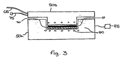
当業者は前記繊維プリフォームを前記モールドに最初に加えることでより良い結果が得られると認識するであろうが、これは前記モールド内でフィルムで覆うために少し長い時間をユーザに与えるため、代わりの実施形態においては、図3に見られるように繊維プリフォーム10の挿入に先立ち樹脂膜20が前記モールド内に加えられる。代わりに、前記プロセスのさらなる迅速化を図るため、前記組み立てられたプリフォーム/フィルムを前記モールドに挿入するに先立ち、前記プリフォームを前記樹脂膜で覆ってもよい。
Those skilled in the art will recognize that better results can be obtained by first adding the fiber preform to the mold, as this gives the user a little longer time to cover with the film in the mold, In an alternative embodiment, a
前記実施形態は、前記要素が使用中に人目につかないため、表面仕上げが重要でない構造複合材料要素の製品を示す。しかし、化粧表面が求められる場合には、図5に概略的に示されるように、樹脂層10または繊維プリフォーム20を加えるに先立ち表面樹脂層のフィルム100が前記モールド内に挿入される。表面樹脂層はこの分野において知られているものであり、また、加熱によって前記繊維プリフォームを通して浸出せず、これはスクリム層がそうすることを防止することによる。そのようなものとして、前記表面樹脂層は、養生されると、滑らかで光沢のある表面仕上げを生じさせるように前記要素の表面上に横たわる。
The embodiment shows a product of a structural composite element where surface finish is not important because the element is not visible during use. However, when a decorative surface is desired, the surface
添付の特許請求の範囲に規定された本発明から逸脱することなしに、さまざまな変更が前記実施形態に施されることは当業者には明らかであろう。 It will be apparent to those skilled in the art that various modifications can be made to the embodiments without departing from the invention as defined in the appended claims.
Claims (10)
繊維または織物のプリフォーム(10)を準備するステップと、
前記プリフォーム(10)とは別個の樹脂膜(20)を準備するステップと、
前記プリフォーム(10)および前記樹脂膜(20)の一方を前記モールド(50)の前記第1のモールドの一半(50a)内に挿入するステップと、
前記プリフォーム(10)および前記樹脂膜(20)の一方が、前記第1のモールドの一半(50a)内の前記プリフォーム(10)および前記樹脂膜(20)の他方の底面上に配置されるように、前記プリフォーム(10)および前記樹脂膜(20)の他方を前記第1のモールドの一半(50a)内に別個に挿入するステップと、
前記第1のモールドの一半(50a)を前記第2のモールドの一半(50b)で閉じるステップと、
前記樹脂膜(20)を前記プリフォーム(10)に含浸させるために圧縮機内で前記モールド(50)を加圧するステップであって、前記モールド(50)は前記方法の最初から最後まで加熱回路を含むモールド加熱システム(80)を用いて一定の加熱温度に維持される、ステップと、
を含む、方法。 A method of manufacturing a structural composite element in a mold (50) comprising a first mold half (50a) and a second mold half (50b), the method comprising:
Providing a fiber or woven preform (10);
Preparing a resin film (20) separate from the preform (10);
Inserting one of the preform (10) and the resin film (20) into one half (50a) of the first mold of the mold (50);
One of said preform (10) and said resin film (20) is disposed on the other of the bottom surface of said preform (10) and the resin layer in the first mold half (50a) (20) Separately inserting the other of the preform (10) and the resin film (20) into one half (50a) of the first mold,
Closing one half (50a) of the first mold with one half (50b) of the second mold;
Pressurizing the mold (50) in a compressor to impregnate the preform (10) with the resin film (20), the mold (50) having a heating circuit from the beginning to the end of the method; Maintained at a constant heating temperature using a mold heating system (80) comprising :
Including a method.
A method of continuously producing a plurality of structural composite elements in a mold (50) comprising a first mold half (50a) and a second mold half (50b), the method comprising: comprising the steps according to any one of 1 to 9, further mold heating system comprising retrieving the composite material element from said mold (50), while said mold (50) is empty, the heating circuit repeating the step of maintaining the mold (50) in the manufacture of continuous composite material element intermediate at a constant heating temperature, then the method according to any one of claims 1 to 9 using (80) Including a step.
Applications Claiming Priority (3)
| Application Number | Priority Date | Filing Date | Title |
|---|---|---|---|
| GB0820267.3 | 2008-11-05 | ||
| GB0820267.3A GB2465159B (en) | 2008-11-05 | 2008-11-05 | Manufacture of a structural composites component |
| PCT/GB2009/002607 WO2010052457A1 (en) | 2008-11-05 | 2009-11-05 | Manufacture of a structural composites component |
Publications (3)
| Publication Number | Publication Date |
|---|---|
| JP2012506804A JP2012506804A (en) | 2012-03-22 |
| JP2012506804A5 JP2012506804A5 (en) | 2012-05-10 |
| JP5509212B2 true JP5509212B2 (en) | 2014-06-04 |
Family
ID=40138369
Family Applications (1)
| Application Number | Title | Priority Date | Filing Date |
|---|---|---|---|
| JP2011533823A Active JP5509212B2 (en) | 2008-11-05 | 2009-11-05 | Manufacturing of structural composite elements |
Country Status (6)
| Country | Link |
|---|---|
| US (1) | US9643363B2 (en) |
| EP (1) | EP2358517B1 (en) |
| JP (1) | JP5509212B2 (en) |
| ES (1) | ES2703596T3 (en) |
| GB (1) | GB2465159B (en) |
| WO (1) | WO2010052457A1 (en) |
Families Citing this family (25)
| Publication number | Priority date | Publication date | Assignee | Title |
|---|---|---|---|---|
| ES2451766T3 (en) * | 2010-11-02 | 2014-03-28 | C-Con Gmbh | Procedure and device for the manufacture of fiber composite components |
| DE102011056686B4 (en) * | 2011-12-20 | 2017-11-23 | Markus Brzeski | A process for producing a fiber composite material, a fiber composite produced by the process and an apparatus for carrying out the process |
| US8869361B2 (en) * | 2011-12-21 | 2014-10-28 | GKN Aerospace Services Structures, Corp. | Method and apparatus for applying a compaction pressure to a fabric preform during wrapping |
| ES2463890B1 (en) * | 2012-02-14 | 2015-01-20 | Carbures Sa | AUTOMATIC AND QUICK MANUFACTURING PROCEDURE OF COMPOSITE STRUCTURES BY MULTI-INJECTION AND COMPRESSION MOLDING |
| DE102012204136A1 (en) * | 2012-03-16 | 2013-09-19 | Voith Patent Gmbh | Vacuum-supported pressing |
| DE102012010271B4 (en) * | 2012-05-25 | 2017-10-12 | Premium Aerotec Gmbh | Process for producing a fiber composite component by means of a vacuum structure |
| GB2502561B (en) * | 2012-05-30 | 2016-03-23 | Gurit Uk Ltd | Press moulding method |
| DE102013004962A1 (en) * | 2012-09-21 | 2014-03-27 | Audi Ag | Method for manufacturing fiber-reinforced plastic component for vehicle chassis, involves melting plastic material of carrier film, by impregnating and hardening semi-finished fiber product |
| DE102013100092B4 (en) * | 2013-01-07 | 2017-01-26 | Thyssenkrupp Steel Europe Ag | Process and apparatus for impregnation testing |
| JP5761867B2 (en) | 2013-01-21 | 2015-08-12 | 株式会社日本製鋼所 | Method for producing fiber reinforced resin base material or resin molded body, and plasticizing dispenser used in this production method |
| GB2515316B (en) * | 2013-06-19 | 2018-02-07 | Creative Composites Ltd | Methods for composite material processing |
| JP6020826B2 (en) * | 2013-07-12 | 2016-11-02 | パナソニックIpマネジメント株式会社 | Fiber-reinforced composite material molding method and fiber-reinforced composite material molding apparatus |
| CN105408080B (en) * | 2013-07-26 | 2018-09-21 | 麦格纳国际公司 | Device for molding and method for compression molded fiber reinforcement type preformed member |
| FR3014008B1 (en) * | 2013-12-04 | 2016-10-28 | Snecma | METHOD FOR IMPREGNATING A FIBROUS PREFORM AND DEVICE FOR IMPLEMENTING SAID METHOD |
| DE102014100882A1 (en) * | 2014-01-27 | 2015-07-30 | Kuka Systems Gmbh | Production technology for components made of fiber-reinforced plastics |
| DE102014109174A1 (en) * | 2014-07-01 | 2016-01-07 | Johnson Controls Interiors Management Gmbh | A method for producing a shaped body from a fiber material and an apparatus for performing the method |
| JP6369720B2 (en) * | 2014-07-03 | 2018-08-08 | 株式会社ジェイテクト | Manufacturing method of rack housing |
| DE102014215964A1 (en) * | 2014-08-12 | 2016-02-18 | Bayerische Motoren Werke Aktiengesellschaft | Method for producing an SMC component provided with a unidirectional fiber layer |
| DE102015201559A1 (en) * | 2015-01-29 | 2016-08-04 | Bayerische Motoren Werke Aktiengesellschaft | Wet pressing method and pressing tool for this |
| US20170157865A1 (en) * | 2015-12-07 | 2017-06-08 | Hattar Tanin LLC | Composite fiber materials |
| US20190224929A1 (en) * | 2016-06-23 | 2019-07-25 | Fpinnovations | Wood pulp fiber- or cellulose filament-reinforced bulk molding compounds, composites, compositions and methods for preparation thereof |
| US20180043642A1 (en) * | 2016-08-11 | 2018-02-15 | GM Global Technology Operations LLC | Mold apparatus and method of using the same |
| KR102127736B1 (en) * | 2018-10-30 | 2020-07-01 | 재단법인 한국탄소융합기술원 | Apparatus and method for manufacturing thermoplastic reinforced panel of aircraft |
| CN111086142A (en) * | 2019-12-26 | 2020-05-01 | 谢祯宇 | Dynamic filling amount process method for rubber material of molded rubber composite product |
| CN115056506A (en) * | 2022-06-16 | 2022-09-16 | 西安交通大学 | Resin film infiltration process resin infiltration process monitoring method and system |
Family Cites Families (13)
| Publication number | Priority date | Publication date | Assignee | Title |
|---|---|---|---|---|
| BE477350A (en) * | 1940-09-07 | |||
| FR2338124A1 (en) * | 1976-01-16 | 1977-08-12 | Ritter Albert | Twin tool system for moulding expanded thermoplastics - for improved thermal efficiency and quicker cycles |
| JPS62183317A (en) | 1986-02-07 | 1987-08-11 | Toray Ind Inc | Continuously molding method for fiber reinforced plastic |
| CA2009530A1 (en) * | 1989-02-10 | 1990-08-10 | Shohei Masui | Method for producing molded article of fiber-reinforced thermoplastic resin |
| DE4335558A1 (en) * | 1993-10-19 | 1995-04-20 | Deutsche Forsch Luft Raumfahrt | Process for manufacturing long fiber reinforced components |
| JP3820268B2 (en) * | 1994-06-17 | 2006-09-13 | トヨタ紡織株式会社 | Method for manufacturing vehicle door trim or vehicle interior material |
| JPH09123198A (en) | 1995-10-30 | 1997-05-13 | Sekisui Chem Co Ltd | Manufacture of decorated molding |
| DE10017493B4 (en) | 2000-04-07 | 2009-02-26 | Daimler Ag | Method for producing a component with an internal tissue |
| US6527533B2 (en) | 2000-12-29 | 2003-03-04 | Ford Global Technologies, Inc. | Processing systems for automated manufacture of preforms |
| WO2002072676A2 (en) * | 2001-01-18 | 2002-09-19 | Ernest Nagy De Nagybaczon | Dynamically forced wetting of materials and products produced therefrom |
| EP2067615B1 (en) | 2006-09-28 | 2016-11-16 | Toray Industries, Inc. | Fiber-reinforced plastic and process for production thereof |
| GB2447964B (en) * | 2007-03-29 | 2012-07-18 | Gurit Uk Ltd | Moulding material |
| US7691311B2 (en) * | 2007-04-27 | 2010-04-06 | Vec Industries, L.L.C. | Method for manufacturing a glass fiber reinforced article, and a glass fiber reinforced article |
-
2008
- 2008-11-05 GB GB0820267.3A patent/GB2465159B/en active Active
-
2009
- 2009-11-05 JP JP2011533823A patent/JP5509212B2/en active Active
- 2009-11-05 ES ES09752446T patent/ES2703596T3/en active Active
- 2009-11-05 US US13/127,960 patent/US9643363B2/en active Active
- 2009-11-05 EP EP09752446.6A patent/EP2358517B1/en active Active
- 2009-11-05 WO PCT/GB2009/002607 patent/WO2010052457A1/en active Application Filing
Also Published As
| Publication number | Publication date |
|---|---|
| GB0820267D0 (en) | 2008-12-10 |
| US9643363B2 (en) | 2017-05-09 |
| US20120038081A1 (en) | 2012-02-16 |
| GB2465159A (en) | 2010-05-12 |
| EP2358517A1 (en) | 2011-08-24 |
| ES2703596T3 (en) | 2019-03-11 |
| WO2010052457A1 (en) | 2010-05-14 |
| GB2465159B (en) | 2013-04-17 |
| JP2012506804A (en) | 2012-03-22 |
| EP2358517B1 (en) | 2018-10-03 |
Similar Documents
| Publication | Publication Date | Title |
|---|---|---|
| JP5509212B2 (en) | Manufacturing of structural composite elements | |
| KR101151966B1 (en) | Rtm molding method and device | |
| EP0722826B1 (en) | Resin transfer molding with honeycomb core and core filler | |
| RU2445206C2 (en) | Method of producing structural component from composite material reinforced by fibers using formed core, and formed core | |
| US20130127092A1 (en) | Moulded multilayer plastics component with continuously reinforced fibre plies and process for producing this component | |
| CN1758012B (en) | Armoured material and its shaping method | |
| CN107073843A (en) | Multiple different fibre-composite components are manufactured with continuous processing high-volume | |
| CN107283878A (en) | The die pressing manufacture craft of embedded co-curing perforation damp composite material | |
| US20060220273A1 (en) | Process for compression moulding liquid resins with structural reinforcements | |
| CN112497786A (en) | Forming method and die for carbon fiber automobile parts | |
| KR101447136B1 (en) | Method for Forming Fiber Reinforced Plastic Composite | |
| EP3625039B1 (en) | Multi-stage resin delivery | |
| JP4292971B2 (en) | FRP manufacturing method and manufacturing apparatus | |
| KR102349669B1 (en) | Forming method of fiber reinforced plastic material | |
| CN116176003A (en) | Fast forming and mass production manufacturing process for CFRP three-dimensional component | |
| JP5362596B2 (en) | Paste composition method, pasting composite mold and pasting device | |
| Ma et al. | Laminating Processes of Thermoset Sandwich Composites | |
| Bader | Molding processes–An overview | |
| Ma et al. | 4 Laminating Processes | |
| JPH1158536A (en) | Manufacture of fiber reinforced resin composite body | |
| JPH1015978A (en) | Manufacture of fiber reinforced resin composite | |
| Smith | The Current Status of Resin Infusion as an Enabling Technology for Toughened Aerospace Structures. | |
| JP2022512189A (en) | Mold for molding automotive trim parts | |
| JPH1110656A (en) | Manufacture of fiber-reinforced resin composite body |
Legal Events
| Date | Code | Title | Description |
|---|---|---|---|
| A521 | Request for written amendment filed |
Free format text: JAPANESE INTERMEDIATE CODE: A523 Effective date: 20120125 |
|
| RD02 | Notification of acceptance of power of attorney |
Free format text: JAPANESE INTERMEDIATE CODE: A7422 Effective date: 20121001 |
|
| A977 | Report on retrieval |
Free format text: JAPANESE INTERMEDIATE CODE: A971007 Effective date: 20121017 |
|
| A521 | Request for written amendment filed |
Free format text: JAPANESE INTERMEDIATE CODE: A821 Effective date: 20121001 |
|
| A131 | Notification of reasons for refusal |
Free format text: JAPANESE INTERMEDIATE CODE: A131 Effective date: 20121113 |
|
| A521 | Request for written amendment filed |
Free format text: JAPANESE INTERMEDIATE CODE: A523 Effective date: 20130213 |
|
| A02 | Decision of refusal |
Free format text: JAPANESE INTERMEDIATE CODE: A02 Effective date: 20131001 |
|
| A521 | Request for written amendment filed |
Free format text: JAPANESE INTERMEDIATE CODE: A523 Effective date: 20140127 |
|
| A521 | Request for written amendment filed |
Free format text: JAPANESE INTERMEDIATE CODE: A523 Effective date: 20140204 |
|
| A911 | Transfer to examiner for re-examination before appeal (zenchi) |
Free format text: JAPANESE INTERMEDIATE CODE: A911 Effective date: 20140207 |
|
| TRDD | Decision of grant or rejection written | ||
| A01 | Written decision to grant a patent or to grant a registration (utility model) |
Free format text: JAPANESE INTERMEDIATE CODE: A01 Effective date: 20140304 |
|
| A61 | First payment of annual fees (during grant procedure) |
Free format text: JAPANESE INTERMEDIATE CODE: A61 Effective date: 20140324 |
|
| R150 | Certificate of patent or registration of utility model |
Ref document number: 5509212 Country of ref document: JP Free format text: JAPANESE INTERMEDIATE CODE: R150 |
|
| R250 | Receipt of annual fees |
Free format text: JAPANESE INTERMEDIATE CODE: R250 |
|
| R250 | Receipt of annual fees |
Free format text: JAPANESE INTERMEDIATE CODE: R250 |
|
| R250 | Receipt of annual fees |
Free format text: JAPANESE INTERMEDIATE CODE: R250 |
|
| R250 | Receipt of annual fees |
Free format text: JAPANESE INTERMEDIATE CODE: R250 |
|
| R250 | Receipt of annual fees |
Free format text: JAPANESE INTERMEDIATE CODE: R250 |
|
| R250 | Receipt of annual fees |
Free format text: JAPANESE INTERMEDIATE CODE: R250 |
|
| R250 | Receipt of annual fees |
Free format text: JAPANESE INTERMEDIATE CODE: R250 |
|
| R250 | Receipt of annual fees |
Free format text: JAPANESE INTERMEDIATE CODE: R250 |