JP5505258B2 - Seedling transplanter - Google Patents
Seedling transplanter Download PDFInfo
- Publication number
- JP5505258B2 JP5505258B2 JP2010241655A JP2010241655A JP5505258B2 JP 5505258 B2 JP5505258 B2 JP 5505258B2 JP 2010241655 A JP2010241655 A JP 2010241655A JP 2010241655 A JP2010241655 A JP 2010241655A JP 5505258 B2 JP5505258 B2 JP 5505258B2
- Authority
- JP
- Japan
- Prior art keywords
- seedling
- preliminary seedling
- preliminary
- switching
- state
- Prior art date
- Legal status (The legal status is an assumption and is not a legal conclusion. Google has not performed a legal analysis and makes no representation as to the accuracy of the status listed.)
- Active
Links
Images


Landscapes
- Transplanting Machines (AREA)
Description
この発明は、走行装置を有する機体の側部に予備の苗載せ台を備えた苗移植機などの作業機に関する。 The present invention relates to a working machine such as a seedling transplanting machine provided with a spare seedling stage on the side of an airframe having a traveling device.
苗植付装置を機体後部に備えた苗移植機において、機体の側部に、複数の予備の苗載せ台からなる予備苗載部を備えた苗移植機が知られている。
下記特許文献1には、複数の予備苗載せ台が上下多段となって平面視で重複した収納状態と、前記複数の予備苗載せ台が前後向きに略一直線状になって展開した展開状態とに、前記複数の予備苗載せ台を切り替え可能に構成した苗移植機が開示されている。この切り替え機構は、1本の長いリンクアームと2本の短いリンクアームからなる平行リンク機構に複数の予備苗載台を取り付け、平行リンク機構の回動によって上下方向に重なり合う状態(平面視で重なる収納状態)と前後方向に略一直線上に並ぶ状態(水平方向に並ぶ展開状態)とに予備苗載せ台の状態を切り替え可能な構成である。
In a seedling transplanter equipped with a seedling planting device at the rear part of the machine body, a seedling transplanter having a spare seedling mounting part composed of a plurality of spare seedling platforms on the side of the machine body is known.
In the following Patent Document 1, a plurality of preliminary seedling platforms are vertically stacked and overlapped in plan view, and a plurality of preliminary seedling platforms are deployed in a substantially straight line in the front-rear direction. In addition, a seedling transplanter configured to switch the plurality of preliminary seedling platforms is disclosed. In this switching mechanism, a plurality of preliminary seedling platforms are attached to a parallel link mechanism composed of one long link arm and two short link arms, and are overlapped in the vertical direction by rotation of the parallel link mechanism (overlapping in plan view). This is a configuration in which the state of the preliminary seedling stage can be switched between a storage state) and a state of being aligned in a substantially straight line in the front-rear direction (a development state of being aligned horizontally).
そして、収納状態から、複数の予備苗載せ台のうちのいずれか一つの可動予備苗載せ台を、固定予備苗載せ台に対して展開状態の姿勢に変更すると、複数の予備苗載せ台が展開状態に切り替えられ、逆に、展開状態から、複数の予備苗載せ台のうちのいずれか一つの可動予備苗載せ台を、固定予備苗載せ台に対して収納状態の姿勢に変更すると、複数の予備苗載せ台が重複状態に切り替えられる構成である。
したがって、複数の予備苗載せ台の状態に切り替えを簡易迅速に行うことができ、複数の予備苗載せ台の状態切り替え作業の作業性を向上させることができる。
Then, when one of the plurality of spare seedling platforms is changed from the storage state to the deployed state with respect to the fixed preliminary seedling platform, the plurality of preliminary seedling platforms are deployed. On the other hand, when the movable standby seedling platform of any one of the plurality of preliminary seedling platforms is changed to the retracted posture with respect to the fixed preliminary seedling platform from the deployed state, It is the structure by which a reserve seedling stand is switched to an overlapping state.
Therefore, it is possible to easily and quickly switch to the state of the plurality of spare seedling platforms, and the workability of the state switching operation of the plurality of preliminary seedling platforms can be improved.
引用文献1、2に記載の苗移植機では、収容状態の予備苗載せ台の停止位置を決めるためのストッパを設けなければならず、予備苗枠の構成が複雑になるとともに、予備苗枠を前記展開状態とするためには、このストッパを手作業で外さなければならないため、作業能率が低下する問題がある。
また、予備苗載せ台を前記展開状態とした際に、苗が予備苗載せ台の前後から落下することを防止する受け板を設けなければならないが、この受け板の上部が柱状であるため、予備苗載せ台に積み込む際、この受け板が苗の移動の抵抗となり、作業者はこの受け板の上部を避けた位置から苗を積み込まねばならず、作業能率が低下する問題がある。
そして、空になった苗箱や、苗箱から苗を掬い取る苗取り板を載置するスペースに乏しいため、機体上に空の苗箱や苗掬い板を置いておく必要があるが、空の苗箱や苗救い板は非常に軽量であるため、風が吹くと飛んで機外に落下してしまい、作業者が落下した苗箱や苗掬い板を拾わねばならず、作業能率が低下する問題がある。
In the seedling transplanting machines described in the cited references 1 and 2, a stopper for determining the stop position of the stored standby seedling stand must be provided, the configuration of the preliminary seedling frame becomes complicated, and In order to obtain the unfolded state, the stopper must be manually removed, which causes a problem that work efficiency is lowered.
In addition, when the preliminary seedling stage is in the expanded state, it is necessary to provide a backing plate that prevents the seedling from falling from the front and back of the preliminary seedling stage, but the upper part of this backing plate is columnar, When loading on the reserve seedling platform, this backing plate resists the movement of the seedling, and the operator has to load the seedling from a position avoiding the upper portion of this backing plate, resulting in a problem that work efficiency is lowered.
And since there is not enough space to place a seedling box that has been emptied or a seedling picking board that picks up seedlings from the seedling box, it is necessary to place an empty seedling box or seedling board on the aircraft. The seedling boxes and seedling rescue boards are very lightweight, so if the wind blows, they will fly off and fall outside the machine, and the operator will have to pick up the seedling boxes and seedling boards that have fallen, reducing work efficiency There is a problem to do.
上記を解消すべく、空の苗箱や苗掬い板を回収する箱を機体上に設けることはできるが、この箱が不要時に作業者の機体操縦や移動の邪魔になる問題がある。
そこで、本発明の課題は、複数の予備苗載せ台を前後にほぼ水平状態に展開状態にした場合にも一つの予備苗載せ台上の苗箱を他の予備苗載せ台にスムーズに移動可能であり、上下方向に重なり合う収納状態にした場合でも苗箱などが落下するおそれのない予備苗載部を備えた苗移植機を提供することである。
In order to solve the above problem, an empty seedling box or a box for collecting seedling-seeking boards can be provided on the aircraft, but there is a problem that this box interferes with the operation and movement of the operator when not needed.
Therefore, the object of the present invention is to smoothly move a seedling box on one spare seedling platform to another spare seedling platform even when a plurality of preliminary seedling platforms are deployed in a substantially horizontal state back and forth. It is to provide a seedling transplanting machine provided with a preliminary seedling mounting portion in which a seedling box or the like is not likely to fall even when stored in a vertically overlapping storage state.
上記課題は、下記構成によって達成される。
すなわち、請求項1に係る発明は、走行車体(2)の後側に圃場に苗を植え付ける植付部(4)を設け、該走行車体(2)に設けた支持機枠(49)に苗箱(68)を載置する複数の予備苗載せ部材(38a,38b,38c)を支持させ、該複数の予備苗載せ部材(38a,38b,38c)をそれぞれ回動自在に連結するリンク部材(39a,39b,39c)を前記支持機枠(49)に設け、該リンク部材(39a,39b,39c)の回動により前記予備苗載せ部材(38a,38b,38c)が前後方向に並ぶ展開状態と前記予備苗載せ部材(38a,38b,38c)が上下方向に並ぶ収納状態に切り替え自在に構成した苗移植機において、前記予備苗載せ部材(38a,38b,38c)の前側端部に前方に向かって突出する前側突出部(38a1,38b1,38c1)を形成し、前記予備苗載せ部材(38a,38b,38c)の後側端部に後方に向かって突出する後側突出部(38a2,38b2,38c2)をそれぞれ形成し、前記複数の予備苗載せ部材(38a,38b,38c)を展開状態にすると、前記走行車体(2)の前側に位置する予備苗載せ部材(38a,38b,38c)の後部突出部(38a2,38b2,38c2)が、前記走行車体(2)の後側に位置する予備苗載せ部材(38a,38b,38c)の前側突出部(38a1,38b1,38c1)と側面視で重複する構成としたことを特徴とする苗移植機である。
The said subject is achieved by the following structure.
That is, the invention is planting platform instill seedlings in the field behind the vehicle body (2) to (4) is provided, seedlings supporting machine frame (49) provided on said vehicle body (2) according to claim 1 a plurality of preliminary seedling member for mounting the box (68) (38a, 38b, 38c) is supported, said plurality of preliminary seedling member (38a, 38b, 38c) rotating respectively rotatably connected to the link member ( 39a, 39 b, provided 39c) to the support machine frame (49), the link member (39a, 39b, 39c) the preliminary seedling member (38a by the rotation of, 38b, 38c) is deployed state aligned in the longitudinal direction and the preliminary seedling member (38a, 38b, 38c) in the seedling transplantation machine is freely configured switch to the accommodated state arranged in the vertical direction, the preliminary seedling member (38a, 38b, 38c) forward to the front end of the Protrude toward Forming a side projecting portion (38a1,38b1,38c1), the preliminary seedling member (38a, 38b, 38c) side protrusion after projecting rearward to the rear end portion of the (38a2,38b2,38c2) respectively forming the plurality of preliminary seedling member (38a, 38b, 38c) when in the deployed state, the rear projection of the preliminary seedling member (38a, 38b, 38c) located on the front side of the vehicle body (2) (38a2,38b2, 38c2) is pre seedling member positioned on the rear side of the vehicle body (2) (38a, 38b, 38c) front projections (38a1, 38b1,38c1) and overlaps in a side view configuration It is a seedling transplanting machine characterized by that.
請求項2に係る発明は、前記予備苗載せ部材(38a,38b,38c)の前側突出部(38a1,38b1,38c1)をそれぞれ後上り傾斜姿勢に形成し、該前側突出部(38a1,38b1,38c1)の後部の上面を当該予備苗載せ部材(38a,38b,38c)の苗載せ面よりも高く形成し、前記予備苗載せ部材(38a,38b,38c)の後側突出部(38a2,38b2,38c2)を当該予備苗載せ部材(38a,38b,38c)の苗載せ面よりも高くし、且つ前記予備苗載せ部材(38a,38b,38c)の前側突出部(38a1,38b1,38c1)の上面と同じか又は前記上面より低くしたことを特徴とする請求項1に記載の苗移植機である。 The invention according to claim 2, wherein the preliminary seedling member (38a, 38b, 38c) formed in the upstream inclined position after front-side extending portion (38a1,38b1,38c1) each, the front protrusion (38A1,38b1, the rear of the top surface of 38c1) preliminary seedling member (38a, 38b, raised than the seedling surface of 38c), said side protrusion after pre seedling member (38a, 38b, 38c) ( 38a2,38b2 , the preliminary seedling members (38a to 38c2), 38b, higher than the seedling surface of 38c), and the front protrusion of the preliminary seedling member (38a, 38b, 38c) of (38a1,38b1,38c1) The seedling transplanter according to claim 1, wherein the seedling transplanter is the same as or lower than the upper surface.
請求項3に係る発明は、前記予備苗載せ部材(38a,38b,38c)の前側突出部(38a1,38b1,38c1)の左右間で、且つ当該予備苗載せ部材(38a,38b,38c)の底部に前側の予備苗載せ部材(38a,38b,38c)の後側突出部(38a2,38b2,38c2)を受ける受け部材(38a3,38b3,38c3)を各々設け、該受け部材(38a3,38b3,38c3)は、前記一対の前側突出部(38a1,38b1,38c1)同士の間の空間部にそれぞれ突出して形成されたことを特徴とする請求項1または2記載の苗移植機である。
The invention according to claim 3, wherein the preliminary seedling member (38a, 38b, 38c) between the left and right front projecting portion of (38a1,38b1,38c1), and the preliminary seedling member (38a, 38b, 38c) of bottom on the front side of the preliminary seedling member (38a, 38b, 38c) side projecting portion (38a2,38b2,38c2) Ru undergoing accepted member (38a3,38b3,38c3) each provided after, receiving only members (38a3, 3. The seedling transplanter according to claim 1 , wherein 38
請求項4に係る発明は、前記支持機枠(49)に苗箱(68)及び苗箱(68)から苗を掬い取る苗掬い板(69)を載置する収容部材(67)を機体に回動可能に取り付け、該収容部材(67)を支持機枠側に回動させると前記支持機枠(49)と略平行姿勢となり、該収容部材(67)を走行車体(2)の内側に回動させると水平姿勢もしくは走行車体(2)の内側に向かって上方傾斜姿勢となる構成としたことを特徴とする請求項1から3のいずれか1項に記載の苗移植機である。
請求項5にかかる発明は、前記支持機枠(49)にリンク部材(39a,39b,39c)の回動支点軸(39b3)を設け、該回動支点軸(39b3)にリンク部材(39a,39b,39c)を回動させる切替ギア(70a)を設け、該切替ギア(70a)に駆動力を供給して展開状態または収納状態に切り替える切替駆動装置(70)を設け、該切替駆動装置(70)を切替操作する切替操作手段(73)を設けたことを特徴とする請求項1から4のいずれか1項に記載の苗移植機である。
請求項6にかかる発明は、前記リンク部材(39a,39b,39c)が接触することにより、前記予備苗載せ部材(38a,38b,38c)を展開状態で停止させる上部切替検出部材(73a1)と、収納状態で停止させる下部切替検出部材(73a2)を予備苗枠(38)に設けたことを特徴とする請求項5に記載の苗移植機である。
なお、本明細書では苗移植機の前進方向に向かって左、右をそれぞれ左、右ということにする。
The invention according to claim 4, wherein Naebako the supporting machine frame (49) to (68) and seedling box plate scooping seedlings scoop seedlings from (68) (69) the placing housing member (67) to the fuselage rotatably mounted, said housing member (67) and rotating the support machine frame side the supporting unit frame (49) and substantially parallel posture, the inside of the housing member (67) the vehicle body (2) The seedling transplanter according to any one of claims 1 to 3, wherein the seedling transplanter is configured to have a horizontal posture or an upward inclined posture toward the inner side of the traveling vehicle body (2) when rotated.
According to a fifth aspect of the present invention, the support frame (49) is provided with a pivot fulcrum shaft (39b3) of the link member (39a, 39b, 39c), and the link member (39a, 39b3) is provided on the pivot fulcrum shaft (39b3). 39b, 39c) is provided with a switching gear (70a), a driving force is supplied to the switching gear (70a), and a switching drive device (70) for switching between the unfolded state and the retracted state is provided. The seedling transplanter according to any one of claims 1 to 4, further comprising a switching operation means (73) for switching the operation 70).
The invention according to
In the present specification, left and right are referred to as left and right, respectively, in the forward direction of the seedling transplanter.
請求項1に係る発明によれば、複数の予備苗載せ部材38a,38b,38cが前後方向に並ぶ展開状態にすると、機体前側の予備苗載せ部材38a,38b,38cの後側突出部38a2,38b2,38c2が機体後側の予備苗載せ部材38a,38b,38cの前側突出部38a1,38b1,38c1と側面視で重複するので、複数の予備苗載せ部材38a,38b,38cを展開状態にすると複数の予備苗載せ部材38a,38b,38cを前後方向に並べることができるので、予備苗載せ部材38a,38b,38cに積み込む苗箱68を円滑に後側に移動させることができ、作業能率が従来より向上する。
According to the first aspect of the present invention, when the plurality of preliminary
請求項2に係る発明によれば、請求項1に係る発明の効果に加えて、予備苗載せ部材38a,38b,38cの前側突出部38a1,38b1,38c1を後上り傾斜姿勢に構成したことにより、複数の予備苗載せ部材38a,38b,38cを展開状態にしたとき、前側の予備苗載せ部材38a,38b,38cから後側の予備苗載せ部材38a,38b,38cに移動させるときに、この後上り傾斜姿勢部分に載り上げて後方に移動することができるので、苗箱68の移動が容易となり、作業能率が向上する。また、前側突出部38a1,38b1,38c1と後側突出部38a2,38b2,38c2の上面を予備苗載せ部材38a,38b,38cの苗載せ面よりも高くしたことにより、複数の予備苗載せ部材38a,38b,38cを収納した形態では、前側突出部38a1,38b1,38c1と後側突出部38a2,38b2,38c2で予備苗載せ部材38a,38b,38cに載置した苗箱68の前後移動を防止することができるので、予備苗載せ部材38a,38b,38cから苗箱68が下方に落下することが防止され、落下した苗箱68を拾う必要が無くなり、作業能率が従来より向上する。
According to the invention according to claim 2, in addition to the effect of the invention according to claim 1, the front projecting portions 38a1, 38b1, and 38c1 of the preliminary
請求項3に係る発明によれば、請求項1または2記載の発明の効果に加えて、各予備苗載せ部材38a,38b,38cの前側突出部38a1,38b1,38c1の左右間に受け部材38a3,38b3,38c3を設けたことにより、前側の予備苗載せ部材38a,38bの後側突出部38a2,38b2を受け部材38b3,38c3で受け止めることができるので、予備苗載せ部材38a,38b,38cが下がり過ぎることがなく、展開状態の予備苗載せ部材38a,38b,38cが確実にほぼ同一平面上に並ぶ姿勢となるため、苗箱68の積み込み作業が容易となり、作業能率が従来より向上する。
According to the invention of claim 3, in addition to the effect of the invention of claim 1 or 2, the receiving member 38a3 is provided between the left and right sides of the front protrusions 38a1, 38b1, 38c1 of the preliminary
また、各予備苗載せ部材38a,38b,38cの底部に受け部材38a3,38b3,38c3を設けたことにより、後側突出部38a2,38b2,38c2の上端部は前側突出部38a1,38b1,38c1の上端部と略同じ高さ、または下側に位置するので、後上り傾斜姿勢の前側突出部38a1,38b1,38c1に載り上げる苗箱68の移動が円滑に行われるため、作業能率が従来より向上する。
Further, by providing the receiving members 38a3, 38b3, 38c3 at the bottoms of the preliminary seedling placing
請求項4に係る発明によれば、請求項1から3のいずれか1項に記載の発明の効果に加えて、苗箱68及び苗掬い板69を収容する収容部材67を支持機枠49に設けたことにより、使っていない苗掬い板69や、苗を植付部4に移動させた後の空の苗箱68を収容部材67で収容することができるので、走行車体2の空きスペースに置いた空の苗箱68や苗掬い板69が風等で飛ばされることがなく、苗箱68や苗掬い板69を拾う必要が無くなり、作業能率が従来より向上する。
According to the invention according to claim 4, in addition to the effect of the invention according to any one of claims 1 to 3, the
また、収容部材67を回動自在に取り付け、収容部材67を機体内側に回動させると水平姿勢もしくは機体内側に向かって上方傾斜姿勢となる構成としたことにより、収容部材67に複数の空の苗箱68を積載したまま作業を継続できるので、空の苗箱68を下ろすために圃場端まで移動する必要がなく、作業能率が従来より向上する。
そして、収容部材67を支持機枠側に回動させることにより、苗の移植作業中など、不要なときには収容部材67を支持機枠49と略平行な姿勢で収納しておくことができるので、収容部材67が作業者の機体操縦や移動を邪魔することが防止される。
請求項5に係る発明によれば、請求項1から4のいずれか1項に記載の発明の効果に加えて、切替操作手段(73)を操作すると切替駆動装置(70)が作動し、予備苗載せ部材(38a,38b,38c)を展開状態と収納状態に切り替えることができるので、作業者が手作業で切り替えを行う必要がなく、作業者の労力が軽減されると共に、作業能率が向上する。
請求項6に係る発明によれば、請求項5に係る発明の効果に加えて、予備苗載せ部材(38a,38b,38c)が展開状態または収納状態になると切替駆動装置(70)を停止させる上部切替検出部材(73a1)と下部切替検出手段(73a2)を設けたことにより、作業者は予備苗載せ部材(38a,38b,38c)が展開状態または収納状態に切替が完了される瞬間を見張る必要が無く、作業能率が向上する。
In addition, the
And by rotating the
According to the invention of
According to the invention of
以下、図面に基づき、本発明の好ましい実施の形態について説明する。
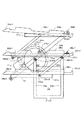
図1及び図2は本発明の苗移植機の典型例である粉粒体繰出し装置として施肥装置を装着した乗用型田植機の側面図と平面図である。この施肥装置付き乗用型田植機1は、走行車体2の後側に昇降リンク装置3を介して苗植付部4が昇降可能に装着され、走行車体2の後部上側に施肥装置5の本体部分が設けられている。搭乗オペレータが乗用型田植機の前進方向に向かって左右方向をそれぞれ左、右といい、前進方向と後進方向をそれぞれ前、後という。
Hereinafter, preferred embodiments of the present invention will be described with reference to the drawings.
FIG. 1 and FIG. 2 are a side view and a plan view of a riding type rice transplanter equipped with a fertilizer application device as a granular material feeding device which is a typical example of the seedling transplanter of the present invention. In this riding type rice transplanter 1 with a fertilizer application, a seedling planting portion 4 is mounted on the rear side of the traveling vehicle body 2 via an elevating link device 3 so that the seedling planting portion 4 can be moved up and down. Is provided. The boarding operator refers to the left and right directions in the forward direction of the riding type rice transplanter as left and right, respectively, and the forward direction and the reverse direction are referred to as forward and backward, respectively.
走行車体2は、駆動輪である左右一対の前輪10,10及び左右一対の後輪11,11(走行装置)を備えた四輪駆動車両であって、機体の前部にミッションケース12が配置され、そのミッションケース12の左右側方に前輪ファイナルケース13,13が設けられ、該左右前輪ファイナルケース13,13の操向方向を変更可能な各々の前輪支持部から外向きに突出する左右前輪車軸に左右前輪10,10が各々取り付けられている。また、ミッションケース12の背面部にメインフレーム15の前端部が固着されており、そのメインフレーム15の後端左右中央部に前後水平に設けた後輪ローリング軸を支点にして後輪ギアケース18,18がローリング自在に支持され、その後輪ギアケース18,18から外向きに突出する後輪車軸に後輪11,11が取り付けられている。
The traveling vehicle body 2 is a four-wheel drive vehicle including a pair of left and right
エンジン20はメインフレーム15の上に搭載されており、該エンジン20の回転動力が、ベルト伝動装置21及び油圧無段変速装置(HST)23を介してミッションケース12に伝達される。ミッションケース12に伝達された回転動力は、該ケース12内のトランスミッションにより変速された後、走行動力と外部取出動力に分離して取り出される。そして、走行動力は、一部が前輪ファイナルケース13,13に伝達されて前輪10,10を駆動すると共に、残りが後輪ギアケース18,18に伝達されて後輪11,11を駆動する。また、外部取出動力は、走行車体2の後部に設けた植付クラッチケース25に伝達され、それから植付伝動軸26によって苗植付部4へ伝動されるとともに、施肥伝動機構28によって施肥装置5へ伝動される。
The engine 20 is mounted on the
エンジン20の上部はエンジンカバー30で覆われており、その上に座席31が設置されている。座席31の前方には各種操作機構を内蔵するフロントカバー32があり、その上方に前輪10,10を操向操作するハンドル34が設けられている。エンジンカバー30及びフロントカバー32の下端左右両側は水平状のフロアステップ35になっている。フロアステップ35は一部格子状になっており(図2参照)、該ステップ35を歩く作業者の靴についた泥が圃場に落下するようになっている。フロアステップ35上の後部は、後輪フェンダを兼ねるリヤステップ36となっている。
The upper part of the engine 20 is covered with an
昇降リンク装置3は平行リンク機構であって、1本の上リンク40と左右一対の下リンク41,41を備えている。これらリンク40,41,41は、その基部側がメインフレーム15の後端部に立設した背面視門形のリンクベースフレーム42に回動自在に取り付けられ、その先端側に縦リンク43が連結されている。そして、縦リンク43の下端部に苗植付部4に回転自在に支承された連結軸44が挿入連結され、連結軸44を中心として苗植付部4がローリング自在に連結されている。
The elevating link device 3 is a parallel link mechanism, and includes a single upper link 40 and a pair of left and right lower links 41, 41. These links 40, 41, 41 are pivotally attached to a rear-view portal-shaped
メインフレーム15に固着した支持部材(図示せず)と上リンク40に一体形成したスイングアーム(図示せず)の先端部との間に昇降油圧式シリンダ46が設けられており、該シリンダ46を油圧で伸縮させることにより、上リンク40が上下に回動し、苗植付部4がほぼ一定姿勢のまま昇降する。
苗植付部4は6条植の構成で、フレームを兼ねる伝動ケース50、マット苗を載せて左右往復動し苗を一株分ずつ各条の苗取出口51a,…に供給するとともに横一列分の苗を全て苗取出口51a,…に供給すると苗送りベルト51b,…により苗を下方に移送する苗載せ台51、苗取出口51a,…に供給された苗を圃場に植付ける苗植付装置52,…、次行程における機体進路を表土面に線引きする左右一対の線引きマーカ75(図1)等を備えている。
An elevating
The seedling planting section 4 has a six-row planting structure, a
苗植付部4の下部には中央にセンターフロート55、その左右両側にサイドフロート56,56がそれぞれ設けられている。これらフロート55,56,56を圃場の泥面に接地させた状態で機体を進行させると、フロート55,56,56が泥面を整地しつつ滑走し、その整地跡に苗植付装置52,…により苗が植え付けられる。各フロート55,56,56は圃場表土面の凹凸に応じて前端側が上下動するように回動自在に取り付けられており、植付作業時にはセンターフロート55の前部の上下動が迎角制御センサ(図示せず)により検出され、その検出結果に応じ前記昇降油圧式シリンダ46を制御する油圧バルブ(図示せず)を切り替えて苗植付部4を昇降させることにより、苗の植付深さを常に一定に維持する。
In the lower part of the seedling planting part 4, a
施肥装置5は、肥料ホッパ60に貯留されている粒状の肥料を繰出部61,…によって一定量ずつ繰り出し、その肥料を施肥ホース62,…でフロート55,56,56の左右両側に取り付けた施肥ガイド(図示せず),…まで導き、施肥ガイド,…の前側に設けた作溝体76(図1),…によって苗植付条の側部近傍に形成される施肥構内に落とし込むようになっている。ブロア用電動モータ53で駆動するブロア58で発生させたエアが、左右方向に長いエアチャンバ59を経由して施肥ホース62,…に吹き込まれ、施肥ホース62,…内の肥料を風圧で強制的に搬送するようになっている。
The
苗植付部4には整地装置の一例であるロータ27(第1ロータ27aと第2ロータ27bの組み合わせを単にロータ27ということがある)が取り付けられている。また、苗載せ台51は苗植付部4の全体を支持する左右方向と上下方向に幅一杯の矩形の支持枠体65の支持ローラ65aをレールとして左右方向にスライドする構成である。
The seedling planting unit 4 is provided with a rotor 27 (an example of a combination of the
また、走行車体2の前部左右両側には、補給用の苗を載せておく一対の予備苗載せ台38,38が機体の前後に張り出す位置と上下に並んだ位置とに回動可能に設けられている。
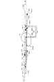
一方の機体側面にある第1予備苗載せ台38a,第2予備苗載せ台38b,第3予備苗載せ台38cを上下三段に配置した場合の側面図を図3に示し、第1予備苗載せ台38a,第2予備苗載せ台38b,第3予備苗載せ台38cを同一平面に配置した場合の側面図を図4に示す。
In addition, on the left and right sides of the front part of the traveling vehicle body 2, a pair of
FIG. 3 shows a side view when the first
予備苗載せ台38は走行車体2のフロアステップ35の下部に基部側を配置した支持機枠49に支持され、移動リンク部材39a,39b,39cを介してそれぞれ上下三段に構成され、第1予備苗載せ台38a、第2予備苗載せ台38b及び第3予備苗載せ台38cからなっている。
これら第1予備苗載せ台38a、第2予備苗載せ台38b及び第3予備苗載せ台38cの底面にはそれぞれ一体的に第1支持枠体37a、第2支持枠体37b及び第3支持枠体37cが取り付けられており、第1支持枠体37aの中央部と第2支持枠体37bの前端部には第1移動リンク部材39aの両端の回動軸39a1,39a2がそれぞれ回動自在に連結し、第1支持枠体37aの後端部と第3支持枠体37cの前端部には第2移動リンク部材39bの両端の回動軸39b1,39b2がそれぞれ回動自在に連結し、さらに第2支持枠体37bの後端部と第3支持枠体37cの中央部には第3移動リンク部材39cの両端の回動軸39c1,39c2とが回動自在に連結している。
回動軸39a2,39b1,39b2,39c1の外周部は、支持枠体37a,37b,37cに溶接して取り付けてられている。そして、支持枠体37a,37b,37cに溶着された回動軸39a2,39b1,39b2,39c1の挿入部(図示せず)に、移動リンク部材39a,39b,39cの支持片(図示せず)を挿し込んで装着する。
The preliminary seedling table 38 is supported by a
A first
The outer peripheral portions of the rotation shafts 39a2, 39b1, 39b2, and 39c1 are attached to the
また、第2移動リンク部材39bのほぼ中央部と第2支持枠体37bのほぼ中央部は回動支点37b1が設けられ、互いに回動自在となっている。
また支持機枠49には前後2つの分岐支柱49a,49bが設けられ、分岐支柱49a,49bの頂部は第2支持枠体37bの下面近くまで達している。そして前側分岐支柱49aの頂部付近には第2リンク部材39bの中央部付近に設けられた回動軸39b3が設けられ、該回動軸39b3を中心として第2リンク部材39bが前側分岐支柱49aの周りを回動自在となってる。前記回動軸39b3は回動支点37b1より下側の第2リンク部材39bに設けられている。また後側分岐支柱49bの頂部付近には第3リンク部材39bの後端部付近に設けられた回動軸39c3が設けられ、該回動軸39c3を中心として第3リンク部材39bが後側分岐支柱49bの周りを回動自在となってる。前記回動軸39c3は回動軸39c1より下側の第3リンク部材39cに設けられている。
In addition, a rotation fulcrum 37b1 is provided at a substantially central portion of the second moving
The
第2予備苗載せ台38bは機体部材である前側分岐支持機枠49aと後側支持機枠49bに固定されておらず、第2移動リンク部材39bが図3に示す状態から回動支点39b3を中心に回動して図4に示す状態になる場合には回動支点39b3が第2予備苗載せ台38bの中央部側面の回動軸37b1より下方にあるため、図3に示す位置より前寄りに第2予備苗載せ台38bが配置される。このとき、第3移動リンク部材39cも図3に示す状態から回動支点39c3を中心に回動して図4に示す状態になる場合には同様に第2予備苗載せ台38cも図3に示す位置より前寄りに配置される。
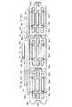
したがって、図5の平面図に示すように第1予備苗載せ台38a、第2予備苗載せ台38b及び第3予備苗載せ台38cをほぼ同一平面上に展開形態とすると、広い苗箱68などの載置平面を得ようとする場合にはこれら3つの予備苗載せ台38a,38b,38cが従来より前寄りに移動して、機体前側端部を圃場の外に突出させることができるので、例えば、畦際でトラックなどから苗を予備苗載せ台38a,38b,38c上に積載する作業が容易となる。
The second preliminary seedling table 38b is not fixed to the front branch
Accordingly, as shown in the plan view of FIG. 5, when the first
また図5の平面図に示すように、第1,第2,第3予備苗載せ台38a,38b,38cの前側両端部に前方に向かって突出する一対の前側突出部38a1,38b1,38c1をそれぞれ形成し、後側端部中央に後方に向かって突出する後側突出部38a2,38b2,38c2をそれぞれ形成している。したがって第1,第2,第3予備苗載せ台38a,38b,38cを展開形態にした場合に、機体前側に位置する予備苗載せ台38a,38bの後部突出部38a2,38b2が機体後側に位置する予備苗載せ台38b,38cの前側突出部38b1,38c1と側面視で重複する位置に配置されることになる。このため第1,第2,第3予備苗載せ台38a,38b,38cが前後方向に並ぶ展開形態にあるときには、第1,第2,第3予備苗載せ台38a,38b,38cを前後方向に部分的に嵌め込み状態で並べることができるので、予備苗載せ台38a,38b,38cに積み込む苗箱68を円滑に後側に移動させることができ、作業能率が従来より向上する。
Further, as shown in the plan view of FIG. 5, a pair of front projecting portions 38a1, 38b1, and 38c1 projecting forward are provided at both front end portions of the first, second, and third
また図3、図4の側面図に示すように、第1〜第3予備苗載せ台38a,38b,38cの前側突出部38a1,38b1,38c1を後上り傾斜形状(後上り傾斜部)にし、該傾斜形状の上面を各予備苗載せ台38a,38b,38cの苗載せ面よりも高くしている。また第1〜第3予備苗載せ台38a,38b,38cの後側突出部38a2,38b2,38c2を各予備苗載せ台38a,38b,38cの苗載せ面よりも高くし、且つ前側突出部38a1,38b1,38c1の上面と同じか又は前記上面より低くしている。
Moreover, as shown to the side view of FIG. 3, FIG. 4, the front side protrusion part 38a1, 38b1, 38c1 of the 1st-3rd
このように前側突出部38a1,38b1,38c1を後上り傾斜部としたので、第1〜第3予備苗載せ台38a,38b,38cを展開状態にしたとき、前側の予備苗載せ台38a,38bから後側の予備苗載せ台38b,38cに苗箱68などを移動させるときに、後上り傾斜部に載り上げて後方に移動することができるので、苗箱68などの移動が容易となり、作業能率が従来より向上する。また、前側突出部38a1,38b1,38c1と後側突出部38a2,38b2,38c2の上面を各予備苗載せ台38a,38b,38cの苗載せ面よりも高くしたことにより、第1〜第3予備苗載せ台38a,38b,38cを収納形態にしたときに、前側突出部38a1,38b1,38c1と後側突出部38a2,38b2,38c2で各予備苗載せ台38a,38b,38cに載置した苗箱68などの前後移動を防止することができるので、各予備苗載せ台38a,38b,38cから苗箱68等が下方に落下することが防止され、落下した苗箱68等を拾う必要が無くなり、作業能率が従来より向上する。
Since the front protrusions 38a1, 38b1, and 38c1 are rearwardly inclined portions in this way, when the first to third
各予備苗載せ台38a,38b,38cの一対の前側突出部38a1,38b1,38c1の左右間で、且つ当該予備苗載せ台38a,38b,38cの底部に前側の予備苗載せ台38a,38b,38cの後側突出部38a2,38b2,38c2を受けるための受け部材38a3,38b3,38c3をそれぞれ設け、該受け部材38a3,38b3,38c3は一対の前側突出部38a1,38b1,38c1同士の間の空間部に突出して形成している。
こうして、各予備苗載せ台38b,38cの前側突出部38b1,38c1の左右間に受け部材38b3,38c3で、それぞれの前側の予備苗載せ台38a,38bの後側突出部38a2,38b2を受け止めることができるので、各予備苗載せ台38a,38b,38cが下がり過ぎることがなく、展開状態の各予備苗載せ台38a,38b,38cが確実にほぼ同一平面上に並ぶ姿勢となるため、苗箱68などの積み込み作業が容易となり、作業能率が従来より向上する。
Front
In this way, the receiving members 38b3 and 38c3 receive the rear protrusions 38a2 and 38b2 of the front
また、予備苗載せ台38a,38b,38cの底部に受け部材38a3,38b3,38c3を設けたことにより、後側突出部38a2,38b2,38c2の上端部は前側突出部38a1,38b1,38c1の上端部と略同じ高さ、または下側に位置するので、後上り傾斜部を有する前側突出部38a1,38b1,38c1に載り上げる苗箱68などの移動が円滑に行われるため、作業能率が従来より向上する。
Further, by providing the receiving members 38a3, 38b3, 38c3 at the bottom of the preliminary seedling mounts 38a, 38b, 38c, the upper ends of the rear protrusions 38a2, 38b2, 38c2 are the upper ends of the front protrusions 38a1, 38b1, 38c1. Since the
また、第1,第2,第3予備苗載せ台38a,38b,38cの左右側面の前後の合計4箇所に苗箱68などの落下を防ぐ第1,第2,第3仕切壁38a4,38b4,38c4をそれぞれ配置している。
また、第2移動リンク部材39bの回動支点39b3を第2予備苗載せ台38bの回動軸37b1と同軸上に設けても良い。この場合は、中央の第2予備苗載せ台38bが前後に移動しない。
In addition, the first, second, and third partition walls 38a4, 38b4 that prevent the
Further, the rotation fulcrum 39b3 of the second moving
上述のように、第1〜第3移動リンク部材39a,39b,39cの作動(回動)により、第1〜第3予備苗載せ台38a,38b,38cが前後方向に並ぶ展開状態と各予備苗載せ台38a,38b,38cが上下方向に並ぶ収納状態とに切り替えられるが、この切り替えは、電動モータ71で駆動する切替駆動装置70とによって行うことができる。切替駆動装置70には、電動モータ71の図示しない回転軸に取り付けられた駆動ギア71aと該駆動ギア71aに噛合する移動リンク部材39bの回動軸39b3と一体回転する円盤状、半円状または半月状の切替ギア70aが設けられている。
該切替ギア70aは前側分岐支柱49aに設けられた移動リンク部材39bの回動軸39b3と同心円状に設けられ、該回動軸39b3と一体回転するので、電動モータ71の駆動で回動軸39b3が回動し、同時に該回動軸39b3と一体の第2移動リンク部材39bが回動することで、第1〜第3移動リンク部材39a,39b,39cが収納状態と展開状態に切り替えられる。
As described above, when the first to third moving
The
そして、切替駆動装置70により予備苗載せ台38a,38b,38cを展開状態と収納状態とに切り替え操作する切替操作手段として切替スイッチ73(ボタン、レバーでもよい)(図1,図2)を座席31近傍に設け、さらに、この切替スイッチ73の操作状態(展開状態または収納状態)を検出する切替スイッチセンサ73a1,73a2を設けた。上部切替スイッチセンサ73a1は予備苗載せ台38a,38b,38cが収納状態になると電動モータ71の作動を止めるリミットスイッチで、下部切替スイッチセンサ71a2は予備苗載せ台38a,38b,38cが展開状態になると電動モータ71の作動を止めるリミットスイッチである。したがって、作業者が「展開状態」または「収納状態」に切替完了する瞬間を見張る必要がなく、作業能率が従来より向上する。
そして、本実施形態では、この切替スイッチセンサ73a1,73a2により検出される操作状態に応じて予備苗載台38a,38b,38cを展開状態と収納状態とに切り替えるように切替駆動装置70を作動する処理を行う制御装置(図示せず)を設けたことを特徴としている。
A switching switch 73 (which may be a button or a lever) (FIGS. 1 and 2) is used as a switching operation means for switching the
In the present embodiment, the switching
従来の乗用型田植機などの苗移植機では、作業者が手動で「展開状態」と「収納状態」とに切り替えなければならず、作業者にとっては負担となり、切り替え作業に労力を費やすという問題がある。また、予備苗載せ台38a,38b,38cの状態を切り替えるための作業は、他の作業を中断して行わなければならず、作業能率が低下するという問題もある。さらに、予備苗載せ台38a,38b,38cの状態を切り替える際の操作具が移動リンク部材39a,39b,39cの一部材であるフレーム等に装備されていると、作業者が移動リンク部材39a,39b,39cのそばで手動操作する際の安全性の問題などもある。
しかし、本構成により、作業者が切替スイッチ73(図1)を操作すると、制御装置よって電動モータ71が駆動して自動的に予備苗載せ台38a,38b,38cを「展開状態」と「収納状態」に切り替えることができるので、作業者が手作業で切り替えを行う必要がなく、作業者の労力や負担を軽減すると共に、作業能率が従来より向上する。
なお、第2移動リンク部材39bの回動支点39b3と第2予備苗載せ台38bの回動軸37b1を異なる位置に設けた図3に示す予備苗載台38の構成でも同様である。
In conventional seedling transplanters such as riding type rice transplanters, the operator has to manually switch between the "deployed state" and the "stored state", which is a burden on the operator and spends labor on the switching work There is. Further, operation for switching the preliminary seedling table 38a, 38b, the state of the 38c must be performed to interrupt the other work, work efficiency is also a problem that the decrease. Furthermore, if the operation tool for switching the state of the
However, according to this configuration, when the operator operates the changeover switch 73 (FIG. 1), the
The same applies to the configuration of the
図7(a),図7(b)の機体正面図に右側の予備苗載せ台部分の要部の構成を示すように、支持支柱49に圃場への苗植付後の苗が入ってない空箱を収納する収容部材67を着脱自在に取り付けている。
図7(c)に斜視図を示すように収容部材は横向きの3本のコ字状丸棒67aと縦向きの2本の直線状丸棒67bを溶接して籠状にして支持支柱49に取り付ける。この際に図7(a)に示すように下側のコ字状丸棒67aの端部を分岐支柱49a,49bに差し込み、該差し込んだ丸棒67aを回動支点として収容部材67の上側を開放状態にして分岐支柱49a,49bに支持させると、収容部材67の開放された上側からから空の苗箱68を載置することができる。苗箱68は丸枠A内に斜視図で示すように2段底の底部を有しているので、空箱を多数積み重ねて配置できる。
As shown in the front view of the airframe in FIGS. 7 (a) and 7 (b), the structure of the main part of the right side seedling stand is not contained in the
As shown in the perspective view of FIG. 7 (c), the housing member is welded to the horizontal three U-shaped round bars 67a and the two vertical straight round bars 67b so as to form a bowl shape on the
また図7(b)に示すように、収容部材67を分岐支柱49a,49b側に回動させることで収容部材67の比較的スペースの狭い開放された上側から苗掬い板69(苗箱68から苗を掬い取る部材)を差し込んで保持することができる。
このように、苗箱68及び苗掬い板69を収容する収容部材67を分岐支柱49a,49bに取り付ける、使っていない苗掬い板69や苗を植付部に移動させた後の空の苗箱68を収容部材67に収容することができるので、機体の空きスペースに置いた空の苗箱68や苗掬い板69が風等で飛ばされることがなく、苗箱68や苗掬い板69を拾う必要が無くなり、作業能率が向上する。
Further, as shown in FIG. 7B, by rotating the
In this way, the
また、図7(a)に示すように収容部材67を回動自在に分岐支柱49a,49bに取り付け、収容部材67を機体内側に回動させると水平姿勢もしくは機体内側に向かって上方傾斜姿勢となる構成としたことにより、収容部材67に複数の空の苗箱68を積載したまま作業を継続できるので、空の苗箱68を下ろすために圃場端まで移動する必要がなく、作業能率が従来より向上する。
そして、図7(b)に示すように、収容部材67を分岐支柱49a,49b側に回動させることにより、苗の移植作業中など、不要なときには収容部材67を分岐支柱49a,49bと略平行な姿勢で収納しておくことができるので、収容部材67が作業者の機体操縦や移動を邪魔することが防止される。
Further, as shown in FIG. 7A, when the accommodating
Then, as shown in FIG. 7 (b), by rotating the
また、図8(a)〜図8(c)に示すように、第1予備苗載せ台38aと第2予備苗載せ台38bの底面に取り付け可能な収容部材67’を設けることもできる。
図8(c)に斜視図で示す収容部材67’は2本のコ字状丸棒67a’と該コ字状丸棒67a’と直交方向に配置した2本の直線状丸棒67b’を溶接して枠体を形成させた構成からなり、第1予備苗載せ台38aと第2予備苗載せ台38bの底面にそれぞれコ字状丸棒67a’を嵌め込み、取り付ける。図8(b)の側面概略図に示すように、第1予備苗載せ台38aと第2予備苗載せ台38bの底部に収容部材67’を取り付けるが、第1予備苗載せ台38aの底部に取り付ける収容部材67’の高さ(B)は第2予備苗載せ台38aの底部に収容部材67’の高さ(A)の約2倍(B≒2A)にしている。
そして縦向きの2本の直線状丸棒67b’は、第3予備苗載せ台38cから第1予備苗載せ台38aに向けて空になった苗箱68を移送させるためのレールとして機能させることができる。これは、次のようにして行う。
Further, as shown in FIGS. 8A to 8C, an
The accommodating
Then, the two straight
すなわち、予備苗載せ台38a,38b,38cを収納状態として苗補給の作業を行った後、図8(b)の側面概略図に示すように、第3予備苗載せ台38cを第2予備苗載せ台38bの底部に取り付けた収容部材67’の高さを揃え、また第2予備苗載せ台38bの底部に取り付けた収容部材67’の高さを第1予備苗載せ台38aの底部に取り付けた収容部材67’の高さと揃えるように予備苗載せ台38a,38b,38cの高さ位置を調整する。電動モータ71と該電動モータ71で作動する予備苗載せ台38a,38b,38c(これらを電動苗枠ということがある。)の切り替えは電動モータ71の駆動により行うので、スイッチ73(図1)の操作で前記切替を途中で止めると、図8の位置で予備苗載せ台38a,38b,38cを停止させることが可能となる。前記電動苗枠の利点の一つに、ストッパ無しで第1予備苗載せ台38aを「展開形態」と「収納形態」の切り替え途中の形態を取らせることができる。さらに、第1予備苗載せ台38aを「展開状態」にすると圃場端の壁にぶつかる場合、展開状態に移行する途中で前記移行の速度を低下させ、第1予備苗載せ台38aだけでも圃場端に近付けて、苗の補充作業者が苗を従来より積み易くすることなどができる。
That is, after carrying out the seedling replenishment operation with the
また逆に苗植付時に苗箱68を補給するとき、予備苗載せ台38a,38b,38cの底部に取り付けた収容部材67’の高さと揃えておき、前方から苗の入った苗箱68を収容部材67’の2本の直線状丸棒67b’からなるレールに載せて後方に送り、後方ではオペレータが苗箱68を苗植付部4へ補給し、その後、第3予備苗載せ台38cを少し下げ、前方2つの収容部材67’の高さが揃ったところで、空の苗箱68を前方へ流す作業を繰り返すことで空箱は前へと送られていく。つまり、この構成により、空いた空箱を次々と前へ送る(戻す)ことができ、畦にいる補助者まで自動的に空箱を送る(戻す)ことができる。苗移植機の上で空箱を置く場所によることはなくなり、また、苗枠とは別にかご等を設ける必要もない。
On the other hand, when the
また、図9(a)〜図9(c)に示すように、第1予備苗載せ台38aと第2予備苗載せ台38bの底面に収容部材67’を設け、図9(c)に斜視図で示す収容部材67’は2本のコ字状丸棒67a’と該コ字状丸棒67a’と直交方向に配置した2本の直線状丸棒67b’を溶接して枠体を形成させた構成からなり、第1予備苗載せ台38aと第2予備苗載せ台38bの底面に取り付ける。図9(a)の側面概略図に示すように、第1予備苗載せ台38aと第2予備苗載せ台38bの底部に収容部材67’を取り付けるが、第1予備苗載せ台38aの底部に取り付ける収容部材67’の高さは第2予備苗載せ台38bの底部に取り付けた収容部材67’の高さを同一とする。そして縦向きの2本の直線状丸棒67b’は空箱の移動用のレールとして第3予備苗載せ台38cから第1予備苗載せ台38aに向けて空になった苗箱68を移送させるためのレールとして機能させることができる。
Further, as shown in FIGS. 9A to 9C, an
すなわち、図9(b)の斜視図に示すように第3予備苗載せ台38cの底面に設けた横軸38c5を中心に第3予備苗載せ台38cを前後方向の傾きが変わるように回動自在としている。そして第3予備苗載せ台38cから空の苗箱68を前方に収容部材67’の2本の直線状丸棒67b’からなるレールを利用して第1予備苗載せ台38aの底部の収容部材67’まで送ることができる。また逆に第1予備苗載せ台38aの底部の収容部材67’に苗の入った苗箱68を供給し、該苗箱68を第3予備苗載せ台38cまで移送することで、後方ではオペレータが苗箱68を苗植付部4の苗載台51へ補給することができる。
That is, as shown in the perspective view of FIG. 9B, the third
図10(a)〜図10(c)(図10(a)に予備苗載せ台の側面概略図、図10(b)に下段予備苗載せ台の斜視図、図10(c)に収容部材の斜視図を示す。)には、図9(a)〜図9(c)と同様の構成からなり、第3予備苗載せ台38cは中央部に苗箱68が通過できる大きさの矩形の穴38c6を設けている。また第1予備苗載せ台38aと第2予備苗載せ台38bの底部に取り付ける収容部材67’は図10(c)に示す2本のコ字状丸棒67a’と該コ字状丸棒67a’と直交方向に配置した2本の直線状丸棒67b’を溶接して得られる枠体から構成するが、第3予備苗載せ台38cの収容部材67’は図10(a)に示すように1本のコ字状丸棒67a’と該コ字状丸棒67a’と直交方向に配置した1本の直線状丸棒67b’を溶接し、しかもレールを構成する直線状丸棒67b’は、第3予備苗載せ台38cの穴38c6に入る苗箱68を誘導するように傾斜配置される。
10 (a) to 10 (c) (FIG. 10 (a) is a schematic side view of the preliminary seedling stage, FIG. 10 (b) is a perspective view of the lower preliminary seedling stage, and FIG. 10 (c) is a housing member. 9 (a) to 9 (c) have a configuration similar to that of FIG. 9 (a) to FIG. 9 (c), and the third
そして第3予備苗載せ台38cの穴38c6から空の苗箱68を前方に収容部材67’の2本の直線状丸棒67b’からなるレールを利用して第1予備苗載せ台38aの底部の収容部材67’まで送ることができる。また逆に第1予備苗載せ台38aの底部の収容部材67’に苗の入った苗箱68を供給し、該苗箱68を第3予備苗載せ台38cまで移送することで、後方ではオペレータが苗箱68を苗植付部4へ補給することができる。
Then, an
図6に示すように、上下複数段の予備苗載せ台38a,38b,38cの底面にそれぞれ第1支持枠体37a、第2支持枠体37b及び第3支持枠体37cが配置されるが、該第1支持枠体37a、第2支持枠体37b及び第3支持枠体37cはそれぞれリンク部材39a,39bに回動自在に取り付けられている。
そして支持枠体37a,37b,37cはそれぞれリンク部材39a,39b,39cに対して機体内側に向かって下向きに傾斜(約5°程度の傾き)配置されている。そのため予備苗載せ台38a,38b,38cに苗箱68を載せたときに、苗植付時の強風でも苗箱68が飛ばないし、圃場の出入り口または悪路を走行中でも苗箱68が予備苗載せ台38a,38b,38cから落下するおそれがない。
As shown in FIG. 6, the first
The support frames 37a, 37b, and 37c are arranged to be inclined downward (inclination of about 5 °) toward the inner side of the machine body with respect to the
また、図11に予備苗載せ台38a,38b,38cの正面概略図を示すが、予備苗載せ台38a,38b,38cの支持支柱49側に、苗箱68の高さよりも上下方向に長い壁突起38a7,38b7,38c7を設け、該壁突起38a7,38b7,38c7の上端部に機体外側に向かって突出部を形成することにより、第1、第2、第3予備苗載せ台38a,38b,38cに積載した苗が機体の傾斜や振動によって浮き上がっても、前記壁突起38a7,38b7,38c7の上端部に形成した突出部が苗を受けるので、苗が落下することが防止され、作業者はこの苗を拾い集める必要がなく、作業者の労力が軽減される。
Further, FIG. 11 shows a schematic front view of the preliminary seedling table 38a, 38b, 38c. On the side of the
また、第1、第2、第3予備苗載せ台38a,38b,38cの横幅を、苗箱68の横幅(左右の長さ)よりも幅広く構成すると、苗箱68を機体前側から積載する際に、壁突起38a7,38b7,38c7に苗が当たって進入が妨げられることがなく、苗の積載作業能率が向上する。
なお、苗箱68を構成する側壁の板厚(D)より3cm〜5cm長く、壁突起38a7,38b7,38c7の内壁面と苗箱68の側壁の隙間(S)を構成すると、上記効果がいっそう発揮される。
Further, when the lateral width of the first, second, and third
If the gap (S) between the inner wall surface of the wall projections 38a7, 38b7, and 38c7 and the side wall of the
図8(a)に例示するように複数段の予備苗載せ台38a,38b,38cに苗箱68が載置されると起動する苗箱検知スイッチ74を設けておき、該スイッチ74が苗箱68を検知すると予備苗載せ台38a,38b,38cの展開形態に作動する電動モータ71が起動し得る構成にしておけば、予備苗載せ台38a,38b,38c上の苗箱68が落下などで苗箱検知スイッチ74が作動しなくなると電動モータ71が起動しなくなり、それ以上の苗箱68の落下を防止できる。
As illustrated in FIG. 8 (a), a seedling
本発明の苗移植機は、田植機に限らず、野菜苗などのその他の苗を植え付ける苗移植機として利用可能性がある。 The seedling transplanter of the present invention is not limited to a rice transplanter, and may be used as a seedling transplanter for planting other seedlings such as vegetable seedlings.
1 施肥装置付き乗用型田植機
2 走行車体
3 昇降リンク装置
4 苗植付部
5 粉粒体繰出し装置(施肥装置)
10 前輪
11 後輪
12 ミッションケース
13 前輪ファイナルケース
15 メインフレーム
18 後輪ギアケース
20 エンジン
21 ベルト伝動装置
23 油圧無段変速装置(HST)
25 植付クラッチケース
26 植付伝動軸
27 ロータ
27a 第1ロータ
27b 第2ロータ
28 施肥伝動機構
30 エンジンカバー
31 座席
32 フロントカバー
34 ハンドル
35 フロアステップ
36 リヤステップ
37a,37b,37c 第1〜第3支持枠体
37b1 回動軸
38a,38b,38c 第1〜第3予備苗載せ台
38a1,38b1,38c1 前側突出部
38a2,38b2,38c2 後側突出部
38a3,38b3,38c3 受け部材
38a4,38b4,38c4 第1〜第3仕切壁
38a7,38b7,38c7 突起
38c5 横軸
39a,39b,39c 第1〜第3移動リンク部材
39a1,39a2,39b1,39b2 回動軸
39c1,39c2,39b3,39c3 回動軸
40 上リンク
41 下リンク
42 リンクベースフレーム
43 縦リンク
44 連結軸
46 昇降油圧式シリンダ
49(49a,49b) 支持機枠
50 伝動ケース
51 苗載せ台
51a 苗取出口
51b 苗送りベルト
52 苗植付装置
53 ブロア用電動モータ
55 センターフロート
56 サイドフロート
58 ブロア
59 エアチャンバ
60 肥料ホッパ
61 繰出部
62 施肥ホース
65 支持枠体
65a 支持ローラ
67,67’ 収容部材
68 苗箱
69 苗掬い板
70 切替駆動装置
70a 切替ギア
71 電動モータ
71a 駆動ギア
73 切替スイッチ
73a1,73a2 切替スイッチセンサ
74 苗箱検知スイッチ
75 線引きマーカ
76 作溝体
DESCRIPTION OF SYMBOLS 1 Riding type rice transplanter with fertilizer application 2 Traveling vehicle body 3 Elevating link device 4
DESCRIPTION OF
25 Planting clutch case 26 Planting transmission shaft 27 Rotor 27a First rotor 27b Second rotor 28 Fertilizer transmission mechanism 30 Engine cover 31 Seat 32 Front cover 34 Handle 35 Floor step 36 Rear steps 37a, 37b, 37c First to third Support frame 37b1 Rotating shafts 38a, 38b, 38c First to third preliminary seedling platforms 38a1, 38b1, 38c1 Front protrusions 38a2, 38b2, 38c2 Rear protrusions 38a3, 38b3, 38c3 Receiving members 38a4, 38b4, 38c4 First to third partition walls 38a7, 38b7, 38c7 Projection 38c5 Horizontal shaft 39a, 39b, 39c First to third moving link members 39a1, 39a2, 39b1, 39b2 Rotating shaft 39c1, 39c2, 39b3, 39c3 Rotating shaft 40 Upper link 41 Lower link 42 Phosphorus Base frame 43 Vertical link 44 Connecting shaft 46 Elevating hydraulic cylinder 49 (49a, 49b) Support machine frame 50 Transmission case 51 Seedling stand 51a Seedling outlet 51b Seedling feed belt 52 Seedling planting device 53 Blower electric motor 55 Center float 56 Side float 58 Blower 59 Air chamber 60 Fertilizer hopper 61 Feeding part 62 Fertilization hose 65 Support frame body 65a Support rollers 67, 67 'Housing member 68 Seedling box 69 Seedling plate 70 Switching drive device 70a Switching gear 71 Electric motor 71a Drive gear 73 selector switch 73a1, 73a2 selector switch sensor 74 seedling box detection switch 75 drawing marker 76 groove forming body
Claims (6)
前記予備苗載せ部材(38a,38b,38c)の前側端部に前方に向かって突出する前側突出部(38a1,38b1,38c1)を形成し、前記予備苗載せ部材(38a,38b,38c)の後側端部に後方に向かって突出する後側突出部(38a2,38b2,38c2)をそれぞれ形成し、前記複数の予備苗載せ部材(38a,38b,38c)を展開状態にすると、前記走行車体(2)の前側に位置する予備苗載せ部材(38a,38b,38c)の後部突出部(38a2,38b2,38c2)が、前記走行車体(2)の後側に位置する予備苗載せ部材(38a,38b,38c)の前側突出部(38a1,38b1,38c1)と側面視で重複する構成としたことを特徴とする苗移植機。 Planting unit instill seedlings in the field behind the vehicle body (2) to (4) is provided, the provided support machine frame the vehicle body (2) (49) to Naebako (68) a plurality of placing the preliminary seedling member (38a, 38b, 38c) is supported, said plurality of preliminary seedling member (38a, 38b, 38c) each pivotally connected to the link member (39a, 39b, 39c) of the support device formed in a frame (49), the link member (39a, 39b, 39c) the preliminary seedling member by the rotation of the (38a, 38b, 38c) the preliminary seedlings and deployment state aligned in the longitudinal direction supporting elements (38a, 38b , 38c) in a seedling transplanting machine configured to be switchable to a stowed state arranged in the vertical direction,
The preliminary seedling member (38a, 38b, 38c) the front projecting portion projecting toward the forward (38a1,38b1,38c1) formed in the front end of, the preliminary seedling member (38a, 38b, 38c) of side protruding portion (38a2,38b2,38c2) respectively formed after projecting rearward to the rear end portion, said plurality of preliminary seedling member (38a, 38b, 38c) when in the deployed state, the vehicle body preliminary seedling member located in front of (2) (38a, 38b, 38c) rear protrusion (38A2,38b2, 38c2) is pre seedling member (38a located on the rear side of the vehicle body (2) , 38b, 38c) and a front projecting portion ( 38a1, 38b1 , 38c1) overlapping in a side view.
Priority Applications (8)
| Application Number | Priority Date | Filing Date | Title |
|---|---|---|---|
| JP2010241655A JP5505258B2 (en) | 2010-10-28 | 2010-10-28 | Seedling transplanter |
| KR1020110071490A KR101331849B1 (en) | 2010-08-18 | 2011-07-19 | Seeding transplanter |
| KR1020110071731A KR101331850B1 (en) | 2010-08-18 | 2011-07-20 | Seeding transplanter |
| CN2011202627851U CN202310549U (en) | 2010-08-18 | 2011-07-22 | Seedling transplanting machine |
| CN201110207461.2A CN102369802B (en) | 2010-08-18 | 2011-07-22 | Seeding transplanter |
| CN201110211363.6A CN102369803B (en) | 2010-08-18 | 2011-07-22 | Seedling transplanter |
| MYPI2011003852A MY164006A (en) | 2010-08-18 | 2011-08-17 | Seedling transplanter |
| MYPI2011003850A MY157408A (en) | 2010-08-18 | 2011-08-17 | Seedling transplanter |
Applications Claiming Priority (1)
| Application Number | Priority Date | Filing Date | Title |
|---|---|---|---|
| JP2010241655A JP5505258B2 (en) | 2010-10-28 | 2010-10-28 | Seedling transplanter |
Publications (3)
| Publication Number | Publication Date |
|---|---|
| JP2012090585A JP2012090585A (en) | 2012-05-17 |
| JP2012090585A5 JP2012090585A5 (en) | 2013-12-19 |
| JP5505258B2 true JP5505258B2 (en) | 2014-05-28 |
Family
ID=46384707
Family Applications (1)
| Application Number | Title | Priority Date | Filing Date |
|---|---|---|---|
| JP2010241655A Active JP5505258B2 (en) | 2010-08-18 | 2010-10-28 | Seedling transplanter |
Country Status (1)
| Country | Link |
|---|---|
| JP (1) | JP5505258B2 (en) |
Families Citing this family (3)
| Publication number | Priority date | Publication date | Assignee | Title |
|---|---|---|---|---|
| JP6024635B2 (en) * | 2013-09-27 | 2016-11-16 | 井関農機株式会社 | Seedling transplanter |
| JP7497701B2 (en) * | 2021-08-02 | 2024-06-11 | 井関農機株式会社 | Ride-on seedling planter |
| JP7533397B2 (en) | 2021-08-25 | 2024-08-14 | 井関農機株式会社 | Ride-on seedling transplanter |
Family Cites Families (4)
| Publication number | Priority date | Publication date | Assignee | Title |
|---|---|---|---|---|
| JP4638810B2 (en) * | 2005-11-21 | 2011-02-23 | 株式会社クボタ | Reserve seedling storage structure of rice transplanter |
| JP5040476B2 (en) * | 2007-06-29 | 2012-10-03 | 井関農機株式会社 | Seedling planting machine |
| JP5023967B2 (en) * | 2007-10-29 | 2012-09-12 | 井関農機株式会社 | Seedling planting machine |
| JP5123709B2 (en) * | 2008-03-31 | 2013-01-23 | 株式会社クボタ | Agricultural machine |
-
2010
- 2010-10-28 JP JP2010241655A patent/JP5505258B2/en active Active
Also Published As
| Publication number | Publication date |
|---|---|
| JP2012090585A (en) | 2012-05-17 |
Similar Documents
| Publication | Publication Date | Title |
|---|---|---|
| JP5040277B2 (en) | Spare seedling stand | |
| JP2008131921A5 (en) | ||
| JP5633547B2 (en) | Seedling transplanter | |
| JP2014068603A5 (en) | ||
| JP5505258B2 (en) | Seedling transplanter | |
| JP5476869B2 (en) | Seedling transplanter | |
| JP2012090585A5 (en) | ||
| JP2021072873A (en) | Work vehicle | |
| JP2012115203A (en) | Seedling transplanter | |
| JP5783276B2 (en) | Seedling transplanter | |
| JP5700357B2 (en) | Seedling transplanter | |
| JP2012170386A5 (en) | ||
| JP5866846B2 (en) | Seedling transplanter | |
| JP5782670B2 (en) | Working machine | |
| JP6816631B2 (en) | Work vehicle | |
| JP5418182B2 (en) | Seedling transplanter | |
| JP2013243951A (en) | Seedling transplanter | |
| JP7243675B2 (en) | Riding seedling transplanter | |
| JP6069903B2 (en) | Spare seedling stand | |
| JP5228640B2 (en) | Passenger rice transplanter | |
| JP2013094078A (en) | Seedling transplanter | |
| JP6024853B1 (en) | Seedling transplanter | |
| JP2019208385A (en) | Work vehicle | |
| JP2013179848A (en) | Seedling transplanter | |
| JP2021083423A (en) | Work vehicle |
Legal Events
| Date | Code | Title | Description |
|---|---|---|---|
| A621 | Written request for application examination |
Effective date: 20130924 Free format text: JAPANESE INTERMEDIATE CODE: A621 |
|
| A521 | Written amendment |
Effective date: 20131030 Free format text: JAPANESE INTERMEDIATE CODE: A523 |
|
| A977 | Report on retrieval |
Effective date: 20140122 Free format text: JAPANESE INTERMEDIATE CODE: A971007 |
|
| TRDD | Decision of grant or rejection written | ||
| A01 | Written decision to grant a patent or to grant a registration (utility model) |
Effective date: 20140218 Free format text: JAPANESE INTERMEDIATE CODE: A01 |
|
| A61 | First payment of annual fees (during grant procedure) |
Free format text: JAPANESE INTERMEDIATE CODE: A61 Effective date: 20140303 |
|
| R150 | Certificate of patent (=grant) or registration of utility model |
Country of ref document: JP Ref document number: 5505258 Free format text: JAPANESE INTERMEDIATE CODE: R150 |