JP5504792B2 - Zoom lens and projection display device - Google Patents
Zoom lens and projection display device Download PDFInfo
- Publication number
- JP5504792B2 JP5504792B2 JP2009220334A JP2009220334A JP5504792B2 JP 5504792 B2 JP5504792 B2 JP 5504792B2 JP 2009220334 A JP2009220334 A JP 2009220334A JP 2009220334 A JP2009220334 A JP 2009220334A JP 5504792 B2 JP5504792 B2 JP 5504792B2
- Authority
- JP
- Japan
- Prior art keywords
- lens
- lens group
- conditional expression
- group
- positive
- Prior art date
- Legal status (The legal status is an assumption and is not a legal conclusion. Google has not performed a legal analysis and makes no representation as to the accuracy of the status listed.)
- Expired - Fee Related
Links
Images


Landscapes
- Projection Apparatus (AREA)
- Lenses (AREA)
Description
本発明は、主にDMDなどの光の反射方向を変えて画像を形成するライトバルブからの画像をスクリーンその他に拡大投射するレンズ口径が小さくコンパクトなズームレンズに関するものである。 The present invention relates to a compact zoom lens having a small lens aperture for enlarging and projecting an image from a light valve for forming an image mainly by changing the reflection direction of light such as DMD.
投射型表示装置においてライトバルブとしてDMD(デジタルマイクロミラーデバイス)を用いる場合、使用する投射用レンズに関して、幾つかのDMD特有の制約が発生する。第1の制約は小型の投射型表示装置を開発する上で最大の制約とも考えられる投射用レンズのF値に関するものである。現在、DMDにおいて、画像を生成する際にマイクロミラーのON及びOFFを表現するために旋回する角度は±12°であり、これにより有効な反射光(有効光)と無効な反射光(無効光)とを切り替えている。 When a DMD (digital micromirror device) is used as a light valve in a projection display device, some DMD-specific restrictions occur with respect to the projection lens used. The first constraint is related to the F value of the projection lens, which is considered to be the greatest constraint in developing a small projection display device. Currently, in the DMD, when the image is generated, the turning angle to represent ON and OFF of the micromirror is ± 12 °, which enables effective reflected light (effective light) and invalid reflected light (ineffective light). ).
従って、DMDをライトバルブとした投射型表示装置においては有効光をとらえる必要があると共に無効光を捉えないことが条件となり、この条件から投射用レンズのF値を導くことが出来る。また、この様な条件は投射用レンズのライトバルブ側の瞳の位置が一定という条件のもとで成立しているため、ズームレンズなどの瞳位置が移動する場合は、移動した分、光量のロスなどが生ずるため、一般的には明るさが問題となりやすい広角端で瞳位置を最適化するなどの配慮も必要となる。第2の制約は光源系との配置に関するものである。小型化の為には投射用レンズのイメージサークルはなるべく小さくしたい為に、DMDに投射用の光束を入力する光源系の配置は限られてしまう。 Therefore, in a projection display device using a DMD as a light valve, it is necessary to capture effective light and not to catch invalid light. From this condition, the F value of the projection lens can be derived. In addition, since such a condition is established under the condition that the position of the pupil on the light valve side of the projection lens is constant, if the pupil position of the zoom lens or the like moves, the amount of light Since loss or the like occurs, it is generally necessary to consider such as optimizing the pupil position at the wide-angle end where brightness tends to be a problem. The second restriction relates to the arrangement with the light source system. Since the image circle of the projection lens is desired to be as small as possible for miniaturization, the arrangement of the light source system for inputting the projection light beam to the DMD is limited.
前述のDMDからの有効光を投射用レンズに入力するには、光源系を投射用レンズとほぼ同じ方向(隣り合わせ)に設置することとなる。また投射用レンズの最もライトバルブ側レンズとライトバルブとの間(すなわち一般的にはバックフォーカス)を投射系と光源系との両光学系で使用することになり、投射用レンズには大きなバックフォーカスを設けなければならないと同時に、光源からの導光スペースを確保するために、ライトバルブ側のレンズ系を小さく設計する必要が生ずる。このことは投射用レンズの光学設計の立場から考えると、投射用レンズの後方付近にライトバルブ側の瞳位置が来るように設計するという制約となる。その一方で、投射用レンズの性能を向上するためには、何枚ものレンズを組み合わせる必要があり、したがってレンズを配置すると投射用レンズの全長は有る程度の長さが必要となり、投射用レンズの全長が長くなれば、入射瞳位置が後方にあるレンズでは当然のことながら前方のレンズ径が大きくなってしまうという小型化とは相反する問題となる。 In order to input effective light from the DMD to the projection lens, the light source system is installed in substantially the same direction (adjacent) as the projection lens. In addition, the projection lens and the light source system are used between the light valve side lens of the projection lens and the light valve (in general, the back focus), and the projection lens has a large back. In addition to providing a focus, it is necessary to design a small lens system on the light valve side in order to secure a light guide space from the light source. From the standpoint of optical design of the projection lens, this is a constraint that the pupil position on the light valve side is located near the rear of the projection lens. On the other hand, in order to improve the performance of the projection lens, it is necessary to combine several lenses. Therefore, when the lenses are arranged, the projection lens needs to have a certain length. If the total length becomes longer, it is a matter of course that the lens having the entrance pupil position on the rear side is contrary to the miniaturization in which the front lens diameter is increased.
この様に、開発を行う上の大きな制約はあるものの、ライトバルブとしてDMDを採用する投射型表示装置は、小型化の上で他の方式よりも有利とされており、現在ではプレゼンテーションを行う際に便利なデータプロジェクタを中心として、携帯可能なコンパクトなものが広く普及してきている。また装置自体をコンパクトに構成するためには、当然のことながら使用される投射用レンズに関しても、コンパクト化の要望は非常に強く、さらにズーム構成による変倍が可能というだけではなく、DMDの中心と投射レンズの光軸をずらして配設する、いわゆるシフト光学系を採用するためにイメージサークルが大きいものを要求するようになりレンズのその広角端の画角の大きい投射レンズが要望されている。またコスト面や生産面を考慮すると非球面レンズをなるべく採用したくない。 In this way, although there are significant restrictions on development, the projection display device that employs DMD as a light valve is advantageous over other methods in terms of miniaturization. Portable portable compact projectors have become widespread, with a focus on convenient data projectors. In addition, in order to make the device itself compact, it is natural that the demand for compactness is very strong with respect to the projection lens used, and not only zooming is possible, but also the center of the DMD. In order to adopt a so-called shift optical system in which the optical axis of the projection lens is shifted, a projection lens having a large image circle is required and a projection lens having a large angle of view at the wide-angle end of the lens is desired. . In view of cost and production, we do not want to use aspherical lenses as much as possible.
しかしながら、携帯可能であることを前提とした投射型表示装置において厚さ寸法を小さくすることはノート型パーソナルコンピュータなどと共に持ち歩くことの多い使われ方をする投射型表示装置では、最も重要な要素であるとも言える。この問題を解決する手段として、例えば特開2007−140474号公報(特許文献1)に開示されているような投射用レンズのコンパクト化設計方法の一例があり、投射型表示装置の小型化に効果的であることが既に知られているが、この発明の実施例によれば非球面レンズを2枚使用しており、コスト面や生産性を考慮に入れると、製品を提供する上で全てに有効な設計手段であるとは言い難い。 However, in a projection display device that is assumed to be portable, reducing the thickness dimension is the most important factor in a projection display device that is often carried around with a notebook personal computer. It can be said that there is. As a means for solving this problem, there is an example of a compact design method for a projection lens as disclosed in, for example, Japanese Patent Application Laid-Open No. 2007-140474 (Patent Document 1), which is effective in reducing the size of a projection display device. However, according to the embodiment of the present invention, two aspherical lenses are used, and in consideration of cost and productivity, all of the products are provided. It is hard to say that it is an effective design tool.
光学補正型ズームレンズは当初35mmスチルカメラ用望遠ズームとして、例えば特開昭56−114919号公報(特許文献2)で開示されている例があるが、焦点距離100から200mmでF4.5の中望遠から望遠クラスのズームレンズとして設計されている。また、ビデオカメラ若しくはスチルビデオカメラ用として特開昭63−210812号公報(特許文献3)で開示されているのは35mmスチルカメラに換算すると50から100(150)mmで標準から中望遠(望遠)域の設計例で、用途が異なるが広角化を実施し設計されている。さらに、特開平5−249377号公報(特許文献4)の例では35mmスチルカメラ用として35(40)から135mmでF4のものが設計されており、一段の広角化と高変倍化がなされているが、これは撮影用のズームレンズとして広角化、高変倍化、明るい光学系が要望されているからであるが、ズームカムを使用前提として設計された同技術分野のズームレンズに勝るものとはなっていない。光学系とそれを保持し、フォーカスや変倍動作を実現する鏡枠機構を含めた範囲でコストを考えた場合、機構部品として高価なズームカムの必要のない光学補正型ズームレンズの採用は有利である。 An optical correction type zoom lens is disclosed as an example of a telephoto zoom for a 35 mm still camera at first, for example, in Japanese Patent Laid-Open No. 56-114919 (Patent Document 2). Designed as a telephoto to telephoto zoom lens. Further, Japanese Patent Application Laid-Open No. 63-210812 (Patent Document 3) discloses a video camera or a still video camera, which is 50 to 100 (150) mm from a standard to a medium telephoto (telephoto) when converted to a 35 mm still camera. ) Area design example, designed for wide-angle use, although the application is different. Further, in the example of Japanese Patent Application Laid-Open No. 5-249377 (Patent Document 4), an F4 lens of 35 (40) to 135 mm is designed for a 35 mm still camera, and a wide-angle and a high zoom ratio are achieved. However, this is because there is a demand for a wide angle, high zoom ratio, and bright optical system as a zoom lens for shooting, but it is superior to the zoom lens of the same technical field designed on the assumption that the zoom cam is used. It is not. When considering the cost in the range including the optical system and the lens frame mechanism that holds it and realizes focusing and zooming, it is advantageous to use an optically corrected zoom lens that does not require an expensive zoom cam as a mechanism part. is there.
しかしながら、薄型投射装置への採用は、前記特開昭56−114919号公報(特許文献2)の例では画角及びF値が達成できず、前記特開昭63−210812号公報(特許文献3)の例では画角が達成できず、前記特開平5−249377号(特許文献4)の例ではF値が達成できない。また、前記各例を通じて、変倍比はより少なくとも良いのであるが、より高解像でなければならず、また前玉径が大きすぎてこれらの開示例の範囲で設計されたレンズは薄型投射装置用の投射レンズとして採用できるものではない。さらに、前記開示例の全てが正パワーを有するレンズ群を移動群とし、これらの移動群に挟まれて負パワーを有するレンズ群を固定配置して変倍を成す構成となっており、本願の構成である負パワーを有するレンズ群を移動群とし、これら移動群に挟まれた正パワーを有するレンズ群を固定群とした開示例ではない。 However, in the example of the thin projection device, the angle of view and the F value cannot be achieved in the example of Japanese Patent Laid-Open No. 56-114919 (Patent Document 2), and the Japanese Patent Laid-Open No. 63-210812 (Patent Document 3). ) Cannot achieve the angle of view, and the F value cannot be achieved in the example of Japanese Patent Laid-Open No. 5-249377 (Patent Document 4). In each of the above examples, the zoom ratio is at least better, but the resolution must be higher, and the lens designed in the scope of these disclosed examples because the front lens diameter is too large is a thin projection. It cannot be used as a projection lens for an apparatus. Furthermore, all of the disclosed examples are configured such that a lens group having positive power is a moving group, and a lens group having negative power is sandwiched between these moving groups and fixedly arranged to perform zooming. This is not a disclosed example in which a lens group having negative power as a configuration is a moving group, and a lens group having positive power sandwiched between these moving groups is a fixed group.
本発明は、前述した事情に鑑み、DMDなどの光の反射方向を変えて画像を形成するライトバルブの特性に適しており、ライトバルブからの画像をスクリーン上或いはその他の壁面等に拡大投射する用途において結像性能が高く、さらにレンズ口径が小さくコンパクトなズームレンズを安価に実現し、コンパクトで明るく、小さな会議室等の限られたスペースでも大きな画面を投射可能で高画質でありながら高価な非球面レンズや光学補正型を採用することによりズームカムを使用せずにコストや生産性をも考慮した薄型の投射型表示装置を安価に提供することを目的としている。 In view of the above-described circumstances, the present invention is suitable for the characteristics of a light valve that forms an image by changing the reflection direction of light, such as DMD, and enlarges and projects an image from the light valve on a screen or other wall surface. A compact zoom lens with high imaging performance and a small lens aperture can be realized at low cost, and it is compact and bright. It can project a large screen even in a limited space such as a small meeting room, and it is high-quality but expensive. By adopting an aspherical lens or an optical correction type, it is an object to provide a low-profile projection type display device that takes cost and productivity into consideration without using a zoom cam.
請求項1記載の発明は、拡大側から順に、全体で正の屈折力を有する第1レンズ群、全体で負の屈折力を有する第2レンズ群、全体で正の屈折力を有する第3レンズ群、全体で負の屈折力を有する第4レンズ群及び全体で正の屈折力を有する第5レンズ群から構成され、広角端から望遠端へ変倍に際して前記第1レンズ群、前記第3レンズ群及び前記第5レンズ群は変倍動作中固定されており、前記第2レンズ群及び前記第4レンズ群は拡大側から縮小側方向へ一体として光軸に沿って移動し、この変倍で移動する前記第2レンズ群のパワーに関して下記条件式(1)を満足し、変倍中固定されている前記第3レンズ群の広角端における倍率に関して下記条件式(2)を満足し、光学系に全体の大きさが下記条件式(3)を満足し、前記第5レンズ群の縮小側に設定される空間に関して下記条件式(4)を満足していることを特徴とする。
(1) −1.2 ≦ fw / fII ≦ −0.85
(2) −0.95 ≦ mIIIw ≦ −0.7
(3) TL / fw ≦ 8.0
(4) 1.75 ≦ bw / fw
ただし、
fw :広角端におけるレンズ全系の合成焦点距離
(第1レンズ群の最も拡大側の面からの物体距離1700mmに合焦の状態)
fII :第2レンズ群の合成焦点距離
mIIIw:広角端における第3レンズ群の合成倍率
TL :第1レンズ群の最も拡大側の面から像面までの距離
(ただし、第1レンズ群の最も拡大側の面からの物体距離1700mmに合焦の状態であり、第5レンズ群の最も縮小側面から像面までは空気換算距離)
bw :第5レンズ群の最も縮小側の面から像面までの距離
(ただし、第1レンズ群の最も拡大側の面からの物体距離1700mmに合焦の状態であり、第5レンズ群の最も縮小側面から像面までは空気換算距離)
条件式(1)は、第2レンズ群のパワーに関する条件である。本発明のズームレンズにおける第2レンズ群は強い負のパワーを有しており、変倍において光軸上を移動する構成要素となっており重要な役割を担っている。また、拡大側に位置する強い負のパワーを有するレンズ群として、前述のDMD等のライトバルブを照明するための光学系を配する為の空間を第5レンズ群とDMD等のライトバルブの構成部品であるカバーガラスCGとの間隔を実際に確保するための光学的に必要となる条件でもある。上限を超えると、第2レンズ群の負のパワーが小さくなり、間隔を必要量確保するのが困難になり、さらに変倍能力も低下し、下限を超えると負のパワーが大きくなり第3レンズ群以降の正レンズ群のパワーを強めなければならず、諸収差のバランスを取ることが困難になる。条件式(2)は、本発明のズームレンズにあって最も特徴のある変倍を司る第3レンズ群の広角端配置における合成倍率に関する条件式である。本発明のズームレンズの変倍を担っているレンズ群は第2レンズ群乃至第4レンズ群で、正パワーの第3レンズ群を変倍中の固定群として当該レンズ群を挟んで負パワーを有する第2レンズ群及び第4レンズ群を一体で、拡大側(広角端)から縮小側(望遠端)へと光軸上を移動させることで実現している。従がって広角端配置の場合、第2レンズ群と第3レンズ群の間には少なくとも変倍時に移動する為に使用する空気間隔が必要である。この空気間隔に関する設定は条件式(2)の数値と密接に関係する。この空気間隔の量は、変倍に関係する各レンズ群のパワー、倍率、収差変動などを考慮しバランスの上で決まるが、条件式(2)の上限を超えると(絶対値が小さいと)空気間隔としては大きく設定可能となるが、一方では光学系全体の大きさに影響を及ぼすため限界値はこれらのバランスで決まってくる。逆に下限を超えると(絶対値が大きいと)空気間隔が大きくとれず、倍率の低下を招き、或いは各群パワーを上げなければならず、諸収差が悪化する。条件式(3)は、光学系の全長に関する条件であり、すなわち小径化の条件となる。上限を超えると全長が大きくなり、したがってレンズが大口径になり、小型、薄型化を損ねてしまう。下限を超えると、諸収差のバランスを取ることが困難となる。条件式(4)は、第5レンズ群の縮小側に設定される空気間隔に関する条件である。いわゆるバックフォーカスに相当する部分であるがライトバルブを照明するための光学系との共用スペースである為、この間隔を確保することが必要となる。従って下限を超えると照明系のスペースが不足し投射型表示装置として設計困難となる。
According to the first aspect of the present invention, in order from the magnifying side, a first lens group having a positive refractive power as a whole, a second lens group having a negative refractive power as a whole, and a third lens having a positive refractive power as a whole Group, a fourth lens group having a negative refractive power as a whole and a fifth lens group having a positive refractive power as a whole, and the first lens group and the third lens at the time of zooming from the wide angle end to the telephoto end The group and the fifth lens group are fixed during zooming operation, and the second lens group and the fourth lens group move integrally along the optical axis from the enlargement side to the reduction side direction. The following conditional expression (1) is satisfied with respect to the power of the moving second lens group, and the following conditional expression (2) is satisfied with respect to the magnification at the wide angle end of the third lens group that is fixed during zooming. The overall size satisfies the following conditional expression (3), and the fifth Characterized in that it satisfies the following conditional expression (4) with respect to space set on the reduction side of the lens group.
(1) -1.2 ≦ f w / f II ≦ -0.85
(2) -0.95 ≤ m IIIw ≤ -0.7
(3) TL / f w ≦ 8.0
(4) 1.75 ≦ b w / f w
However,
f w : Combined focal length of the entire lens system at the wide-angle end (focusing on an object distance of 1700 mm from the most magnified surface of the first lens group)
f II: a second lens unit of the composite focal length m III W: Synthesis magnification of the third lens group at the wide-angle end TL: distance from the closest to the magnification side surface of the first lens group to the image plane (provided that the first lens group The object distance is 1700 mm from the most magnified surface, and the distance from the most reduced side surface to the image surface of the fifth lens group is the air equivalent distance)
b w: distance between the most reduction side surface of the fifth lens group to the image plane (where a state of focusing on an object distance 1700mm between the most magnification side surface of the first lens group, the fifth lens group ( Air conversion distance from the most reduced side to the image plane )
Conditional expression (1) is a condition relating to the power of the second lens group. The second lens group in the zoom lens of the present invention has a strong negative power, and is a component that moves on the optical axis in zooming, and plays an important role. In addition, as a lens group having a strong negative power located on the enlargement side, a space for arranging the optical system for illuminating the light valve such as the above-described DMD is provided with a structure of the fifth lens group and the light valve such as the DMD. This is also an optically necessary condition for actually securing the distance from the cover glass CG as a component. If the upper limit is exceeded, the negative power of the second lens group will be reduced, making it difficult to secure the required distance, and the zooming power will also be reduced. If the lower limit is exceeded, the negative power will increase and the third lens will become larger. The power of the positive lens group after the group must be increased, and it becomes difficult to balance various aberrations. Conditional expression (2) is a conditional expression related to the combination magnification at the wide-angle end arrangement of the third lens group that controls the most characteristic zooming in the zoom lens according to the present invention. The lens groups responsible for zooming of the zoom lens of the present invention are the second lens group to the fourth lens group. The third lens group having positive power is set as a fixed group during zooming, and the negative power is sandwiched between the lens groups. The second lens group and the fourth lens group are integrated and moved on the optical axis from the enlargement side (wide angle end) to the reduction side (telephoto end). Accordingly, in the case of the wide-angle end arrangement, an air interval used for moving at least during zooming is required between the second lens group and the third lens group. This setting related to the air interval is closely related to the numerical value of the conditional expression (2). The amount of this air interval is determined on balance in consideration of the power, magnification, aberration variation, etc. of each lens group related to zooming, but if the upper limit of conditional expression (2) is exceeded (the absolute value is small) The air interval can be set large, but on the other hand, the limit value is determined by these balances because it affects the overall size of the optical system. On the contrary, if the lower limit is exceeded (when the absolute value is large), the air interval cannot be made large, the magnification is reduced, or the power of each group must be increased, and various aberrations deteriorate. Conditional expression (3) is a condition relating to the total length of the optical system, that is, a condition for reducing the diameter. If the upper limit is exceeded, the total length becomes large, and therefore the lens becomes large in diameter, and the reduction in size and thickness is impaired. When the lower limit is exceeded, it becomes difficult to balance various aberrations. Conditional expression (4) is a condition regarding the air interval set on the reduction side of the fifth lens group. Although this is a portion corresponding to a so-called back focus, it is a common space with the optical system for illuminating the light valve, so it is necessary to ensure this interval. Therefore, if the lower limit is exceeded, the space of the illumination system is insufficient, and it becomes difficult to design as a projection display device.
請求項2記載の発明は、前記第1レンズ群は、全体として正パワーを有するが、何枚ものレンズで構成することは前玉有効径を大きくすることに繋がるため、正の屈折力を有するレンズ(以下正レンズ)1枚にて構成されていることを特徴とする。
In the invention according to
請求項3記載の発明は、前記第2レンズ群は、最も拡大側に、拡大側に凸のメニスカス形状で負の屈折力を有するレンズ(以下負レンズ)を配置し、全体で少なくとも二枚の負レンズを含む二乃至三枚のレンズにて構成され、最も拡大側に配置される前記負レンズのパワーに関して下記条件式(5)を満足し、縮小側面の形状の特徴に関して下記条件式(6)を満足していることを特徴とする。
(5) −0.5 ≦ fw / fII1 ≦ −0.45
(6) 0.85 ≦ fw / rII2 ≦ 1.2
ただし、
fII1:第2レンズ群において最も拡大側に配置されるレンズの焦点距離
rII2:第2レンズ群において最も拡大側に配置されるレンズの縮小側面の曲率半径
条件式(5)は、第2レンズ群の最も拡大側に配置されるレンズのパワーに関する条件である。前述のように第2レンズ群は、全体として強い負パワーを有するレンズ群で特に画角を確保するために重要な場所に配置されているといえる。したがって、最も拡大側に配置されるレンズに関しても大きな負のパワーを有しており、このことは光学系に要求される画角とバックフォーカスに密接に関係しているためであり、本発明のズームレンズでいえば第2レンズ群の最も拡大側に配置されるレンズの負パワーを増大することは、第5レンズ群とDMD等のライトバルブの構成部品であるカバーガラスCGとの空気間隔を確保した上で要求画角を実現し、かつ小型化に有効であるが、条件式(5)の上限を超えるとレンズの負パワーが強くなり色収差と像面湾曲が発生し、収差の補正が困難になり、下限を超えるとレンズの負パワーが弱くなり第5レンズ群とDMD等のライトバルブの構成部品であるカバーガラスCGとの空気間隔、いわゆるバックフォーカスに相当する部分を長く取ることが困難になる。条件式(6)は、レンズ全系の歪曲収差とコマ収差補正のための条件式である。前述の第2レンズ群の最も拡大側に配置されるレンズの縮小側の面形状に関するもので、強いパワーを持たせながら、拡大側の光線束に対して概ね同心的形状とすることで、根本的に収差の発生を抑えた形状としている。したがって上限を超えると、球面収差、コマ収差が補正不足となり、下限を超えると逆に補正過剰になる。
According to a third aspect of the present invention, the second lens group includes, on the most enlargement side, a lens having a negative meniscus shape and a negative refractive power (hereinafter referred to as a negative lens) on the enlargement side. Consists of two to three lenses including a negative lens, the following conditional expression (5) is satisfied with respect to the power of the negative lens arranged on the most magnified side, and the following conditional expression (6 ) Is satisfied.
(5) −0.5 ≦ f w / f II1 ≦ −0.45
(6) 0.85 ≦ f w / r II2 ≦ 1.2
However,
f II1 : Focal length r II2 of the lens arranged closest to the enlargement side in the second lens group: Curvature radius of the reduction side surface of the lens arranged closest to the enlargement side in the second lens group Conditional expression (5) This is a condition relating to the power of the lens arranged on the most enlarged side of the lens group. As described above, it can be said that the second lens group is a lens group having a strong negative power as a whole, and is disposed at an important place particularly for securing a field angle. Therefore, the lens arranged on the most magnified side also has a large negative power, which is closely related to the angle of view and back focus required for the optical system. In the case of a zoom lens, increasing the negative power of the lens disposed on the most enlarged side of the second lens group increases the air gap between the fifth lens group and the cover glass CG which is a component of a light valve such as a DMD. While ensuring the required angle of view and ensuring size reduction, if the upper limit of conditional expression (5) is exceeded, the negative power of the lens will increase, causing chromatic aberration and curvature of field, and correcting aberrations. When the lower limit is exceeded, the negative power of the lens is weakened, and the air gap between the fifth lens group and the cover glass CG that is a component of the light valve such as the DMD, the portion corresponding to the so-called back focus is lengthened. It becomes difficult to take. Conditional expression (6) is a conditional expression for correcting distortion and coma aberration of the entire lens system. This relates to the shape of the lens on the reduction side of the lens arranged closest to the enlargement side of the second lens group described above, and is basically concentric with respect to the light bundle on the enlargement side while having strong power. In particular, it has a shape that suppresses the occurrence of aberrations. Therefore, when the upper limit is exceeded, spherical aberration and coma aberration are undercorrected, and when the lower limit is exceeded, overcorrection is conversely performed.
請求項4記載の発明は、前記第3レンズ群は、最も拡大側に正レンズを配置し、全体で二枚の正レンズ及び一枚の負レンズにて構成され、最も拡大側に配置される前記正レンズのパワーに関して下記条件式(7)を満足し、拡大側から二番目乃至三番目に配置されるレンズの分散特性の関係が下記条件式(8)を満足していることを特徴とする。
(7) 0.2 ≦ fw / fIII1 ≦ 0.46
(8) 42 ≦|vIII2 − vIII3|
ただし、
fIII1:第3レンズ群において最も拡大側に配置されるレンズの焦点距離
vIII2:第3レンズ群の拡大側から二番目に配置されるレンズのアッベ数
vIII3:第3レンズ群の拡大側から三番目に配置されるレンズのアッベ数
第3レンズ群の構成の特徴を詳しくみると、拡大側に有効径の大きい正レンズを配置して、やや大きめの空気間隔を設けるのが望ましく、その後全体として正パワーを有する負レンズ、正レンズの順番の色消し系、或いは正レンズ、負レンズの順番の色消し系を配置しており、拡大側の正レンズを前群、色消し系を後群とすると、第3レンズ群前群は、第2レンズ群の強い負パワーで跳ね上げられたマージナル光線を略平行光束に戻しておいて、第3レンズ群後群でさらに集光光束として続く第4レンズ群に綱いている。その際前群と後群の間の空気間隔は大きいことは望ましいものの他の条件等との兼ね合いで大きく取れない場合もある。第3レンズ群前群と後群の間の空気間隔は一般的な各レンズのパワーを下げて基本的な収差発生を抑制する作用を有している一方、前群の位置では軸上光束と周辺光束が分離気味にレンズに入射しているため周辺光束の光線高が大きいが、空気間隔を設けることによって後群の位置では周辺光束の光線高が小さくして、続く第4レンズ群内において周辺光束の主光線が光軸と交わるための準備をしている。条件式(7)は第3レンズ群前群のパワーに関するものであるが、基本的に第2レンズ群で跳ね上げられたマージナル光線を略平行光束に戻すに必要となるパワーである。上限を超えると単レンズであるため色収差を始め各収差の悪化を招くこととなり、下限を超えると後群の負担が大きくなることにより第3レンズ群としての収差バランスを崩す結果となる。続く条件式(8)は第3レンズ群後群における分散係数に関するものであるが、前群での発生を含め第3レンズ群の色消しに関するものである。従がって下限未満では十分な色消しを得ることが出来なくなる。
According to a fourth aspect of the present invention, the third lens group includes a positive lens on the most magnifying side, and is composed of two positive lenses and one negative lens as a whole, and is disposed on the most magnifying side. The following conditional expression (7) is satisfied with respect to the power of the positive lens, and the relationship between the dispersion characteristics of the lenses arranged second to third from the magnifying side satisfies the following conditional expression (8). To do.
(7) 0.2 ≦ f w / f III1 ≦ 0.46
(8) 42 ≦ | v III2 −v III3 |
However,
f III1: the most focal length of the lens disposed on the magnification side in the third lens group v III2: third Abbe number of the lens element which is disposed second from the enlargement side of the lens group v III3: expansion side of the third lens group The Abbe number of the third lens from the third lens group. When examining the characteristics of the configuration of the third lens group in detail, it is desirable to arrange a positive lens with a large effective diameter on the enlargement side and provide a slightly larger air gap. As a whole, a negative lens with positive power and an achromatic system in the order of positive lens, or an achromatic system in the order of positive lens and negative lens are arranged, with the positive lens on the enlargement side in the front group and the achromatic system in the rear As a group, the front group of the third lens group returns the marginal light beam bounced up with the strong negative power of the second lens group to a substantially parallel light beam, and continues as a condensed light beam in the rear group of the third lens group. In the fourth lens group The In this case, it may be difficult to obtain a large air gap between the front group and the rear group in consideration of other conditions that are desirable. The air gap between the front group and the rear group of the third lens group has a function of lowering the power of each general lens and suppressing the occurrence of basic aberrations. Since the peripheral light flux is incident on the lens in a separated manner, the light flux of the peripheral light flux is large. However, by providing an air interval, the light flux of the peripheral light flux is reduced at the position of the rear group, and in the subsequent fourth lens group. Preparations are made for the principal ray of the peripheral luminous flux to intersect the optical axis. Conditional expression (7) relates to the power of the front group of the third lens group, but is basically the power required to return the marginal light beam jumped up by the second lens group to a substantially parallel light beam. If the upper limit is exceeded, since it is a single lens, chromatic aberration and other aberrations will be worsened, and if the lower limit is exceeded, the burden on the rear group will increase, resulting in a loss of aberration balance as the third lens group. The following conditional expression (8) relates to the dispersion coefficient in the rear group of the third lens group, but relates to the achromaticity of the third lens group including the occurrence in the front group. Therefore, if it is less than the lower limit, sufficient achromaticity cannot be obtained.
請求項5記載の発明は、前記第4レンズ群は、拡大側から順に負レンズ、正レンズ及び負レンズを配して構成され、群全体として有するパワーに関して下記条件式(9)を満足し、拡大側から二番目に配置されるレンズのパワーに関して下記条件式(10)を満足し、構成する前記負レンズと前記正レンズの分散特性の関係が下記条件式(11)を満足し、構成する前記正レンズの屈折率が下記条件式(12)を満足していることを特徴とする。
(9) −0.95 ≦ fw / fIV ≦ −0.65
(10) 0.75 ≦ fw / fIV2 ≦ 1.25
(11) 8.0 ≦ VIVn − VIVp
(12) 1.72 ≦ nIVp
ただし、
fIV :第4レンズ群の合成焦点距離
fIV2:第4レンズ群において拡大側から二番目に配置されるレンズの焦点距離
VIVn:第4レンズ群を構成する負レンズのアッベ数の平均値
VIVp:第4レンズ群を構成する正レンズのアッベ数の平均値
nIVp:第4レンズ群を構成する正レンズのd線における屈折率
条件式(9)は、第4レンズ群のパワーに関するものである。第4レンズ群は変倍を主に担っているために強い負のパワーが付与されている。従がって上限を超えるような(絶対値の小さい)パワーでは変倍量を小さくするか或いは光学系全体の大きさも大きくなるためコンパクトなズームレンズとはならない。逆に下限を超えるような(絶対値の大きい)パワーを与えてしまうと、続く第5レンズ群の正のパワーを増大しなければならなくなるため、全体の収差バランスが悪化してしまう。一方本来このような光学補正型の変倍光学系では移動群となるレンズ群のパワーが略等しいことが変倍中のフォーカス移動を無くする(無視しうる量とする)ための条件であるが、このことはカメラなどの交換レンズにおいて変倍時のフォーカス移動量が最大でも焦点深度内に収めなければならないための条件であり、本発明のズームレンズのように投射型表示装置に採用する場合にはその条件をそのままあてはめなくとも良い。投射型表示装置用の光学系としてはフォーカス移動を必ずしも無視し得る量にする必要はなく、変倍によるフォーカス移動での投射画像のボケが微小であれば、再度フォーカス調整をすること至極簡単であるため問題にはならない。それよりもズームカムを省略できるというコスト的な利点、サイズ的な利点の方が優位な条件である。このような制約の中では条件式(1)で表現されている第2レンズ群のパワー、条件式(9)で表現されている第4レンズのパワーの関係は問題ではなくフォーカス移動を良好な範囲で維持することが可能である。条件式(10)は、第4レンズ群において拡大側から二番目に配置される正レンズのパワーに関するものであるが、第4レンズ群として強い負のパワーを有する中で、正パワーの強いレンズが配置されているのはレンズ系全体でのペッツバール和のバランスを良好に維持することが目的である。従がって上限、下限のどちらを超えてもバランスとしては望ましくなく周辺性能の悪化を招くこととなるが上限を超えた場合には、加えて第4レンズ群全体の負パワーの損出を招き易く、変倍比を下げざるを得なくなる。条件式(11)は、第4レンズ群としての色消し条件であり、下限を超えると変倍時における色収差変動が大きくなりズーム全域について良好な性能を維持することが出来ない。数値自身が一般的な光学ガラスの範囲を考えると小さくみえるが、それは第4レンズ群に使用される硝材が正レンズ、負レンズに関係なく一応に屈折率が高いことが理由である。条件式(12)は、第4レンズ群の中程に配置される正レンズの屈折率を示している。前述のように、第4レンズ群では高屈折率を有する負、正、負のレンズがやや大きい空気間隔を保ちつつ配されている。これはペッツバール和を改善するための像面湾曲に有利な構成方法であるとともに、周辺像点に対する主光線が第4レンズ群内で光軸と交差することから、コマ収差や特に球面収差に大きな影響を及ぼすためこれらについても有利な形状を保持する必要があり、これらの要件を鑑みると当該レンズの屈折率は高い方が望ましく、条件式(12)の下限を超えるとこれらの良好な特性が維持出来なくなる。
The invention according to claim 5 is configured such that the fourth lens group includes a negative lens, a positive lens, and a negative lens in order from the magnification side, and satisfies the following conditional expression (9) with respect to the power of the entire group, The following conditional expression (10) is satisfied with respect to the power of the lens disposed second from the magnifying side, and the relationship between the dispersion characteristics of the negative lens and the positive lens constituting the lens satisfies the following conditional expression (11). The refractive index of the positive lens satisfies the following conditional expression (12).
(9) −0.95 ≦ f w / f IV ≦ −0.65
(10) 0.75 ≦ f w / f IV2 ≦ 1.25
(11) 8.0 ≦ V IVn −V IVp
(12) 1.72 ≦ n IVp
However,
f IV : Combined focal length f IV2 of the fourth lens group: Focal length V IVn of the lens arranged second from the magnification side in the fourth lens group: Average value of Abbe number of the negative lens constituting the fourth lens group V IVp : Average value of Abbe numbers of positive lenses constituting the fourth lens group n IVp : Refractive index of the positive lens constituting the fourth lens group at the d-line Conditional expression (9) relates to the power of the fourth lens group Is. Since the fourth lens group is mainly responsible for zooming, strong negative power is applied. Accordingly, when the power exceeds the upper limit (small absolute value), the zooming amount is reduced or the overall size of the optical system is increased, so that a compact zoom lens cannot be obtained. Conversely, if a power exceeding the lower limit (a large absolute value) is given, the positive power of the subsequent fifth lens group must be increased, so that the overall aberration balance is deteriorated. On the other hand, in such an optical correction type variable power optical system, the power of the lens group as a moving group is substantially equal, which is a condition for eliminating focus movement during zooming (with a negligible amount). This is a condition for an interchangeable lens such as a camera that needs to be within the depth of focus even when the focus movement amount at the time of zooming is maximum, and is used in a projection display device like the zoom lens of the present invention. It is not necessary to apply the conditions as they are. As an optical system for a projection display device, it is not always necessary to set the amount of focus movement to be negligible, and if the blur of the projected image due to focus movement by zooming is very small, it is extremely easy to adjust the focus again. Because there is no problem. The cost advantage and the size advantage that the zoom cam can be omitted are more advantageous conditions. Under such constraints, the relationship between the power of the second lens group expressed by the conditional expression (1) and the power of the fourth lens expressed by the conditional expression (9) is not a problem, and the focus movement is good. It is possible to maintain a range. Conditional expression (10) relates to the power of the positive lens arranged second from the magnifying side in the fourth lens group. The lens having strong positive power among the fourth lens group having strong negative power. The purpose of is to maintain a good balance of Petzval sum in the entire lens system. Therefore, if either the upper limit or the lower limit is exceeded, the balance is not desirable, and the peripheral performance is deteriorated. However, if the upper limit is exceeded, the negative power loss of the entire fourth lens group is additionally reduced. It is easy to invite and the zoom ratio must be lowered. Conditional expression (11) is an achromatic condition for the fourth lens group. If the lower limit is exceeded, chromatic aberration variation during zooming increases, and good performance cannot be maintained over the entire zoom range. The numerical value itself seems to be small when considering the range of general optical glass. This is because the glass material used for the fourth lens group has a refractive index that is high regardless of whether it is a positive lens or a negative lens. Conditional expression (12) represents the refractive index of the positive lens arranged in the middle of the fourth lens group. As described above, in the fourth lens group, negative, positive, and negative lenses having a high refractive index are arranged while maintaining a slightly large air gap. This is an advantageous construction method for field curvature to improve the Petzval sum, and the chief ray with respect to the peripheral image point intersects the optical axis in the fourth lens group. In view of these requirements, it is desirable that the refractive index of the lens is high, and when the lower limit of conditional expression (12) is exceeded, these good characteristics are obtained. It cannot be maintained.
請求項6記載の発明は、前記第5レンズ群は、拡大側から順に正レンズ、負レンズ及び正レンズを配して構成され、群全体として有するパワーに関して下記条件式(13)を満足し、構成する前記正レンズと前記負レンズの分散特性の関係が下記条件式(14)を満足し、構成する前記負レンズの屈折率が下記条件式(15)を満足していることを特徴とする。
(13) 0.6 ≦ fw / fV ≦ 0.75
(14) 25 ≦ VVp − VVn
(15) 1.78 ≦ nVn
ただし、
fV :第5レンズ群の合成焦点距離
VVp :第5レンズ群を構成する正レンズのアッベ数
VVn :第5レンズ群を構成する負レンズのアッベ数
nVn :第5レンズ群を構成する負レンズのd線における屈折率
条件式(13)は、第5レンズ群のパワーに関するものである。第5レンズ群は、レンズ群としては最も縮小側に配置され変倍動作中固定されているため、マスター系或いはリレー系に準ずる役割を担っている。すなわち変倍に関係なく第1レンズ群乃至第4レンズ群で発生し、補正不十分な収差を最終的に補正すると共に所定の寸法、仕様に合わせる機能を有する。従がって上限を超えると所定の仕様とするには各群のパワーも増大することになり性能を維持することが出来ない。あるいは逆に性能を維持するためには光学系の構成枚数を増やす必要が生ずる。また、下限を超えると第5レンズ群による最終的な性能調整効果が不十分となってしまう。条件式(14)は、第5レンズ群の色補正条件である。単色収差を補正するには、各レンズのパワーが過大とならないことが必要で、そのためには条件式(14)を満たす正レンズ、負レンズのアッベ数であることが必要な条件となり、下限を超えると色収差の補正が困難となる。条件式(15)は、第5レンズ群を構成する負レンズに用いられる硝材の屈折率に関する条件である。第5レンズ群を構成する負レンズは拡大側から二番目、すなわち中央に配置されるが、縮小側の正レンズと接合の状態で用いるのが望ましい。これはこの部分系において、接合レンズに屈折率差をあたえることで、接合面での球面収差補正能力を維持しつつ像面湾曲補正の効果をも期待できるからである。従がって条件式(15)で下限を超える硝材の選択をするとこのような効果を期待出来なくなり、像面湾曲が過剰補正され、さらに球面収差がアンダーとなり易い。
The invention according to claim 6 is configured such that the fifth lens group includes a positive lens, a negative lens, and a positive lens in order from the magnification side, and satisfies the following conditional expression (13) with respect to the power of the entire group, The relationship between the dispersion characteristics of the positive lens and the negative lens constituting the lens satisfies the following conditional expression (14), and the refractive index of the negative lens constituting the zoom lens satisfies the following conditional expression (15). .
(13) 0.6 ≦ f w / f V ≦ 0.75
(14) 25 ≤ V Vp -V Vn
(15) 1.78 ≦ n Vn
However,
f V : Composite focal length of the fifth lens group V Vp : Abbe number of the positive lens constituting the fifth lens group V Vn : Abbe number of the negative lens constituting the fifth lens group n Vn : Constructing the fifth lens group Refractive index of the negative lens at the d-line Conditional expression (13) relates to the power of the fifth lens group. Since the fifth lens group is disposed on the most reduction side as the lens group and is fixed during zooming operation, it has a role equivalent to the master system or the relay system. That is, it has a function of correcting aberrations that occur in the first lens group to the fourth lens group regardless of zooming and that are insufficiently corrected and are adjusted to predetermined dimensions and specifications. Therefore, if the upper limit is exceeded, the power of each group will increase to achieve a predetermined specification, and the performance cannot be maintained. Conversely, in order to maintain the performance, it is necessary to increase the number of components of the optical system. If the lower limit is exceeded, the final performance adjustment effect by the fifth lens group becomes insufficient. Conditional expression (14) is a condition for color correction of the fifth lens group. In order to correct the monochromatic aberration, it is necessary that the power of each lens does not become excessive. For that purpose, the Abbe number of the positive lens and the negative lens satisfying the conditional expression (14) is necessary, and the lower limit is set. If it exceeds, it will be difficult to correct chromatic aberration. Conditional expression (15) is a condition relating to the refractive index of the glass material used for the negative lens constituting the fifth lens group. The negative lens constituting the fifth lens group is arranged second from the enlargement side, that is, in the center, but is desirably used in a state of being joined to the positive lens on the reduction side. This is because, in this partial system, by providing the cemented lens with a refractive index difference, it is possible to expect the effect of field curvature correction while maintaining the spherical aberration correction capability on the cemented surface. Accordingly, if a glass material exceeding the lower limit is selected in the conditional expression (15), such an effect cannot be expected, the field curvature is excessively corrected, and the spherical aberration is likely to be under.
請求項7記載の発明は、このように本発明によるズームレンズを投射型表示装置に搭載することにより装置全体を小型化することが可能となり、携帯にも便利な薄型の投射型表示装置を提供することが出来、さらにコストを低く維持することに効果的である。 The invention according to claim 7 provides a thin projection display device that can be downsized as a whole by mounting the zoom lens according to the present invention on the projection display device, and is convenient for carrying. It is effective to keep the cost low.
本発明によれば、DMDなどのライトバルブの特性に適した結像性能が高くコンパクトでコスト面や生産面でも効果的なズームレンズを実現し、コンパクトで高画質の投射型表示装置を安価に提供することが出来る。 According to the present invention, a zoom lens having high imaging performance suitable for the characteristics of a light valve such as a DMD and high in compactness and effective in terms of cost and production is realized, and a compact and high-quality projection display device is made inexpensive. Can be provided.
本発明のズームレンズは、拡大側から順に、全体で正の屈折力を有する第1レンズ群、全体で負の屈折力を有する第2レンズ群、全体で正の屈折力を有する第3レンズ群、全体で負の屈折力を有する第4レンズ群及び全体で正の屈折力を有する第5レンズ群から構成され、広角端から望遠端へ変倍に際して前記第1レンズ群、前記第3レンズ群及び前記第5レンズ群は変倍動作中固定されており、前記第2レンズ群及び前記第4レンズ群は拡大側から縮小側方向へ一体として光軸に沿って移動し、この変倍で移動する前記第2レンズ群のパワーに関して下記条件式(1)を満足し、変倍中固定されている前記第3レンズ群の広角端における倍率に関して下記条件式(2)を満足し、光学系に全体の大きさが下記条件式(3)を満足し、前記第5レンズ群の縮小側に設定される空間に関して下記条件式(4)を満足していることを特徴とする。
(1) −1.2 ≦ fw / fII ≦ −0.85
(2) −0.95 ≦ mIIIw ≦ −0.7
(3) TL / fw ≦ 8.0
(4) 1.75 ≦ bw / fw
ただし、
fw :広角端におけるレンズ全系の合成焦点距離
(第1レンズ群の最も拡大側の面からの物体距離1700mmに合焦の状態)
fII :第2レンズ群の合成焦点距離
mIIIw:広角端における第3レンズ群の合成倍率
TL :第1レンズ群の最も拡大側の面から像面までの距離
(ただし、第1レンズ群の最も拡大側の面からの物体距離1700mmに合焦の状態であり、第5レンズ群の最も縮小側面から像面までは空気換算距離)
bw :第5レンズ群の最も縮小側の面から像面までの距離
(ただし、第1レンズ群の最も拡大側の面からの物体距離1700mmに合焦の状態であり、第5レンズ群の最も縮小側面から像面までは空気換算距離)
条件式(1)は、第2レンズ群のパワーに関する条件である。本発明のズームレンズにおける第2レンズ群は強い負のパワーを有しており、変倍において光軸上を移動する構成要素となっており重要な役割を担っている。また、拡大側に位置する強い負のパワーを有するレンズ群として、前述のDMD等のライトバルブを照明するための光学系を配する為の空間を第5レンズ群とDMD等のライトバルブの構成部品であるカバーガラスCGとの間隔を実際に確保するための光学的に必要となる条件でもある。上限を超えると、第2レンズ群の負のパワーが小さくなり、間隔を必要量確保するのが困難になり、さらに変倍能力も低下し、下限を超えると負のパワーが大きくなり第3レンズ群以降の正レンズ群のパワーを強めなければならず、諸収差のバランスを取ることが困難になる。条件式(2)は、本発明のズームレンズにあって最も特徴のある変倍を司る第3レンズ群の広角端配置における合成倍率に関する条件式である。本発明のズームレンズの変倍を担っているレンズ群は第2レンズ群乃至第4レンズ群で、正パワーの第3レンズ群を変倍中の固定群として当該レンズ群を挟んで負パワーを有する第2レンズ群及び第4レンズ群を一体で、拡大側(広角端)から縮小側(望遠端)へと光軸上を移動させることで実現している。従がって広角端配置の場合、第2レンズ群と第3レンズ群の間には少なくとも変倍時に移動する為に使用する空気間隔が必要である。この空気間隔に関する設定は条件式(2)の数値と密接に関係する。この空気間隔の量は、変倍に関係する各レンズ群のパワー、倍率、収差変動などを考慮しバランスの上で決まるが、条件式(2)の上限を超えると(絶対値が小さいと)空気間隔としては大きく設定可能となるが、一方では光学系全体の大きさに影響を及ぼすため限界値はこれらのバランスで決まってくる。逆に下限を超えると(絶対値が大きいと)空気間隔が大きくとれず、倍率の低下を招き、或いは各群パワーを上げなければならず、諸収差が悪化する。条件式(3)は、光学系の全長に関する条件であり、すなわち小径化の条件となる。上限を超えると全長が大きくなり、したがってレンズが大口径になり、小型、薄型化を損ねてしまう。下限を超えると、諸収差のバランスを取ることが困難となる。条件式(4)は、第5レンズ群の縮小側に設定される空気間隔に関する条件である。いわゆるバックフォーカスに相当する部分であるがライトバルブを照明するための光学系との共用スペースである為、この間隔を確保することが必要となる。従って下限を超えると照明系のスペースが不足し投射型表示装置として設計困難となる。
The zoom lens of the present invention includes, in order from the magnification side, a first lens group having a positive refractive power as a whole, a second lens group having a negative refractive power as a whole, and a third lens group having a positive refractive power as a whole. , A fourth lens group having a negative refractive power as a whole and a fifth lens group having a positive refractive power as a whole, and the first lens group and the third lens group upon zooming from the wide angle end to the telephoto end. The fifth lens group is fixed during zooming operation, and the second lens group and the fourth lens group move along the optical axis as a unit from the enlargement side to the reduction side, and move by this zooming. The following conditional expression (1) is satisfied with respect to the power of the second lens group, and the following conditional expression (2) is satisfied with respect to the magnification at the wide angle end of the third lens group that is fixed during zooming. The overall size satisfies the following conditional expression (3), Characterized in that it satisfies the following conditional expression (4) with respect to space set on the reduction side of the lens unit.
(1) -1.2 ≦ f w / f II ≦ -0.85
(2) -0.95 ≤ m IIIw ≤ -0.7
(3) TL / f w ≦ 8.0
(4) 1.75 ≦ b w / f w
However,
f w : Combined focal length of the entire lens system at the wide-angle end (focusing on an object distance of 1700 mm from the most magnified surface of the first lens group)
f II: a second lens unit of the composite focal length m III W: Synthesis magnification of the third lens group at the wide-angle end TL: distance from the closest to the magnification side surface of the first lens group to the image plane (provided that the first lens group The object distance is 1700 mm from the most magnified surface, and the distance from the most reduced side surface to the image surface of the fifth lens group is the air equivalent distance)
b w: distance between the most reduction side surface of the fifth lens group to the image plane (where a state of focusing on an object distance 1700mm between the most magnification side surface of the first lens group, the fifth lens group ( Air conversion distance from the most reduced side to the image plane )
Conditional expression (1) is a condition relating to the power of the second lens group. The second lens group in the zoom lens of the present invention has a strong negative power, and is a component that moves on the optical axis in zooming, and plays an important role. In addition, as a lens group having a strong negative power located on the enlargement side, a space for arranging the optical system for illuminating the light valve such as the above-described DMD is provided with a structure of the fifth lens group and the light valve such as the DMD. This is also an optically necessary condition for actually securing a distance from the cover glass CG as a component. If the upper limit is exceeded, the negative power of the second lens group will be reduced, making it difficult to secure the required distance, and the zooming power will also be reduced. If the lower limit is exceeded, the negative power will increase and the third lens will become larger. The power of the positive lens group after the group must be increased, and it becomes difficult to balance various aberrations. Conditional expression (2) is a conditional expression related to the combination magnification at the wide-angle end arrangement of the third lens group that controls the most characteristic zooming in the zoom lens according to the present invention. The lens groups responsible for zooming of the zoom lens of the present invention are the second lens group to the fourth lens group. The third lens group having positive power is set as a fixed group during zooming, and the negative power is sandwiched between the lens groups. The second lens group and the fourth lens group are integrated and moved on the optical axis from the enlargement side (wide angle end) to the reduction side (telephoto end). Accordingly, in the case of the wide-angle end arrangement, an air interval used for moving at least during zooming is required between the second lens group and the third lens group. This setting related to the air interval is closely related to the numerical value of the conditional expression (2). The amount of this air interval is determined on balance in consideration of the power, magnification, aberration variation, etc. of each lens group related to zooming, but if the upper limit of conditional expression (2) is exceeded (the absolute value is small) The air interval can be set large, but on the other hand, the limit value is determined by these balances because it affects the overall size of the optical system. On the contrary, if the lower limit is exceeded (when the absolute value is large), the air interval cannot be made large, the magnification is reduced, or the power of each group must be increased, and various aberrations deteriorate. Conditional expression (3) is a condition relating to the total length of the optical system, that is, a condition for reducing the diameter. If the upper limit is exceeded, the total length becomes large, and therefore the lens becomes large in diameter, and the reduction in size and thickness is impaired. When the lower limit is exceeded, it becomes difficult to balance various aberrations. Conditional expression (4) is a condition regarding the air interval set on the reduction side of the fifth lens group. Although this is a portion corresponding to a so-called back focus, it is a common space with the optical system for illuminating the light valve, so it is necessary to ensure this interval. Therefore, if the lower limit is exceeded, the space of the illumination system is insufficient, and it becomes difficult to design as a projection display device.
また、前記第1レンズ群は、全体として正パワーを有するが、何枚ものレンズで構成することは前玉有効径を大きくすることに繋がるため、正の屈折力を有するレンズ(以下正レンズ)1枚にて構成されていることが望ましい。 The first lens group has a positive power as a whole. However, a lens having a positive refracting power (hereinafter referred to as a positive lens) is constituted by a number of lenses, which leads to an increase in the effective diameter of the front lens. It is desirable to be composed of one sheet.
また、前記第2レンズ群は、最も拡大側に、拡大側に凸のメニスカス形状で負の屈折力を有するレンズ(以下負レンズ)を配置し、全体で少なくとも二枚の負レンズを含む二乃至三枚のレンズにて構成され、最も拡大側に配置される前記負レンズのパワーに関して下記条件式(5)を満足し、縮小側面の形状の特徴に関して下記条件式(6)を満足していることが望ましい。
(5) −0.5 ≦ fw / fII1 ≦ −0.45
(6) 0.85 ≦ fw / rII2 ≦ 1.2
ただし、
fII1:第2レンズ群において最も拡大側に配置されるレンズの焦点距離
rII2:第2レンズ群において最も拡大側に配置されるレンズの縮小側面の曲率半径
条件式(5)は、第2レンズ群の最も拡大側に配置されるレンズのパワーに関する条件である。前述のように第2レンズ群は、全体として強い負パワーを有するレンズ群で特に画角を確保するために重要な場所に配置されているといえる。したがって、最も拡大側に配置されるレンズに関しても大きな負のパワーを有しており、このことは光学系に要求される画角とバックフォーカスに密接に関係しているためであり、本発明のズームレンズでいえば第2レンズ群の最も拡大側に配置されるレンズの負パワーを増大することは、第5レンズ群とDMD等のライトバルブの構成部品であるカバーガラスCGとの空気間隔を確保した上で要求画角を実現し、かつ小型化に有効であるが、条件式(5)の上限を超えるとレンズの負パワーが強くなり色収差と像面湾曲が発生し、収差の補正が困難になり、下限を超えるとレンズの負パワーが弱くなり第5レンズ群とDMD等のライトバルブの構成部品であるカバーガラスCGとの空気間隔、いわゆるバックフォーカスに相当する部分を長く取ることが困難になる。条件式(6)は、レンズ全系の歪曲収差とコマ収差補正のための条件式である。前述の第2レンズ群の最も拡大側に配置されるレンズの縮小側の面形状に関するもので、強いパワーを持たせながら、拡大側の光線束に対して概ね同心的形状とすることで、根本的に収差の発生を抑えた形状としている。したがって上限を超えると、球面収差、コマ収差が補正不足となり、下限を超えると逆に補正過剰になる。
Further, the second lens group includes a lens having a negative refractive power (hereinafter, a negative lens) having a convex meniscus shape on the enlargement side on the most enlargement side, and includes at least two negative lenses as a whole. Consists of three lenses, the following conditional expression (5) is satisfied with respect to the power of the negative lens arranged on the most magnified side, and the following conditional expression (6) is satisfied with respect to the characteristics of the shape of the reduction side surface. It is desirable.
(5) −0.5 ≦ f w / f II1 ≦ −0.45
(6) 0.85 ≦ f w / r II2 ≦ 1.2
However,
f II1 : Focal length r II2 of the lens arranged closest to the enlargement side in the second lens group: Curvature radius of the reduction side surface of the lens arranged closest to the enlargement side in the second lens group Conditional expression (5) This is a condition relating to the power of the lens arranged on the most enlarged side of the lens group. As described above, it can be said that the second lens group is a lens group having a strong negative power as a whole, and is disposed at an important place particularly for securing a field angle. Therefore, the lens arranged on the most magnified side also has a large negative power, which is closely related to the angle of view and back focus required for the optical system. In the case of a zoom lens, increasing the negative power of the lens disposed on the most enlarged side of the second lens group increases the air gap between the fifth lens group and the cover glass CG which is a component of a light valve such as a DMD. While ensuring the required angle of view and ensuring size reduction, if the upper limit of conditional expression (5) is exceeded, the negative power of the lens will increase, causing chromatic aberration and curvature of field, and correcting aberrations. When the lower limit is exceeded, the negative power of the lens is weakened, and the air gap between the fifth lens group and the cover glass CG that is a component of the light valve such as the DMD, the portion corresponding to the so-called back focus is lengthened. It becomes difficult to take. Conditional expression (6) is a conditional expression for correcting distortion and coma aberration of the entire lens system. This relates to the shape of the lens on the reduction side of the lens arranged closest to the enlargement side of the second lens group described above, and is basically concentric with respect to the light bundle on the enlargement side while having strong power. In particular, it has a shape that suppresses the occurrence of aberrations. Therefore, when the upper limit is exceeded, spherical aberration and coma aberration are undercorrected, and when the lower limit is exceeded, overcorrection is conversely performed.
また、前記第3レンズ群は、最も拡大側に正レンズを配置し、全体で二枚の正レンズ及び一枚の負レンズにて構成され、最も拡大側に配置される前記正レンズのパワーに関して下記条件式(7)を満足し、拡大側から二番目乃至三番目に配置されるレンズの分散特性の関係が下記条件式(8)を満足していることが望ましい。
(7) 0.2 ≦ fw / fIII1 ≦ 0.46
(8) 42 ≦|vIII2 − vIII3|
ただし、
fIII1:第3レンズ群において最も拡大側に配置されるレンズの焦点距離
vIII2:第3レンズ群の拡大側から二番目に配置されるレンズのアッベ数
vIII3:第3レンズ群の拡大側から三番目に配置されるレンズのアッベ数
第3レンズ群の構成の特徴を詳しくみると、拡大側に有効径の大きい正レンズを配置して、やや大きめの空気間隔を設けるのが望ましく、その後全体として正パワーを有する負レンズ、正レンズの順番の色消し系、或いは正レンズ、負レンズの順番の色消し系を配置しており、拡大側の正レンズを前群、色消し系を後群とすると、第3レンズ群前群は、第2レンズ群の強い負パワーで跳ね上げられたマージナル光線を略平行光束に戻しておいて、第3レンズ群後群でさらに集光光束として続く第4レンズ群に綱いている。その際前群と後群の間の空気間隔は大きいことは望ましいものの他の条件等との兼ね合いで大きく取れない場合もある。第3レンズ群前群と後群の間の空気間隔は一般的な各レンズのパワーを下げて基本的な収差発生を抑制する作用を有している一方、前群の位置では軸上光束と周辺光束が分離気味にレンズに入射しているため周辺光束の光線高が大きいが、空気間隔を設けることによって後群の位置では周辺光束の光線高が小さくして、続く第4レンズ群内において周辺光束の主光線が光軸と交わるための準備をしている。条件式(7)は第3レンズ群前群のパワーに関するものであるが、基本的に第2レンズ群で跳ね上げられたマージナル光線を略平行光束に戻すに必要となるパワーである。上限を超えると単レンズであるため色収差を始め各収差の悪化を招くこととなり、下限を超えると後群の負担が大きくなることにより第3レンズ群としての収差バランスを崩す結果となる。続く条件式(8)は第3レンズ群後群における分散係数に関するものであるが、前群での発生を含め第3レンズ群の色消しに関するものである。従がって下限未満では十分な色消しを得ることが出来なくなる。
The third lens group includes a positive lens on the most magnifying side and is composed of two positive lenses and one negative lens as a whole, and the power of the positive lens arranged on the most magnifying side. It is desirable that the following conditional expression (7) is satisfied, and the relationship between the dispersion characteristics of the lenses disposed second to third from the magnification side satisfies the following conditional expression (8).
(7) 0.2 ≦ f w / f III1 ≦ 0.46
(8) 42 ≦ | v III2 −v III3 |
However,
f III1: the most focal length of the lens disposed on the magnification side in the third lens group v III2: third Abbe number of the lens element which is disposed second from the enlargement side of the lens group v III3: expansion side of the third lens group The Abbe number of the third lens from the third lens group. When examining the characteristics of the configuration of the third lens group in detail, it is desirable to arrange a positive lens with a large effective diameter on the enlargement side and provide a slightly larger air gap. As a whole, a negative lens with positive power and an achromatic system in the order of positive lens, or an achromatic system in the order of positive lens and negative lens are arranged, with the positive lens on the enlargement side in the front group and the achromatic system in the rear As a group, the front group of the third lens group returns the marginal light beam bounced up with the strong negative power of the second lens group to a substantially parallel light beam, and continues as a condensed light beam in the rear group of the third lens group. In the fourth lens group The In this case, it may be difficult to obtain a large air gap between the front group and the rear group in consideration of other conditions that are desirable. The air gap between the front group and the rear group of the third lens group has a function of lowering the power of each general lens and suppressing the occurrence of basic aberrations. Since the peripheral light flux is incident on the lens in a separated manner, the light flux of the peripheral light flux is large. However, by providing an air interval, the light flux of the peripheral light flux is reduced at the position of the rear group, and in the subsequent fourth lens group. Preparations are made for the principal ray of the peripheral luminous flux to intersect the optical axis. Conditional expression (7) relates to the power of the front group of the third lens group, but is basically the power required to return the marginal light beam jumped up by the second lens group to a substantially parallel light beam. If the upper limit is exceeded, since it is a single lens, chromatic aberration and other aberrations will be worsened, and if the lower limit is exceeded, the burden on the rear group will increase, resulting in a loss of aberration balance as the third lens group. The following conditional expression (8) relates to the dispersion coefficient in the rear group of the third lens group, but relates to the achromaticity of the third lens group including the occurrence in the front group. Therefore, if it is less than the lower limit, sufficient achromaticity cannot be obtained.
また、前記第4レンズ群は、拡大側から順に負レンズ、正レンズ及び負レンズを配して構成され、群全体として有するパワーに関して下記条件式(9)を満足し、拡大側から二番目に配置されるレンズのパワーに関して下記条件式(10)を満足し、構成する前記負レンズと前記正レンズの分散特性の関係が下記条件式(11)を満足し、構成する前記正レンズの屈折率が下記条件式(12)を満足していることが望ましい。
(9) −0.95 ≦ fw / fIV ≦ −0.65
(10) 0.75 ≦ fw / fIV2 ≦ 1.25
(11) 8.0 ≦ VIVn − VIVp
(12) 1.72 ≦ nIVp
ただし、
fIV :第4レンズ群の合成焦点距離
fIV2:第4レンズ群において拡大側から二番目に配置されるレンズの焦点距離
VIVn:第4レンズ群を構成する負レンズのアッベ数の平均値
VIVp:第4レンズ群を構成する正レンズのアッベ数の平均値
nIVp:第4レンズ群を構成する正レンズのd線における屈折率
条件式(9)は、第4レンズ群のパワーに関するものである。第4レンズ群は変倍を主に担っているために強い負のパワーが付与されている。従がって上限を超えるような(絶対値の小さい)パワーでは変倍量を小さくするか或いは光学系全体の大きさも大きくなるためコンパクトなズームレンズとはならない。逆に下限を超えるような(絶対値の大きい)パワーを与えてしまうと、続く第5レンズ群の正のパワーを増大しなければならなくなるため、全体の収差バランスが悪化してしまう。一方本来このような光学補正型の変倍光学系では移動群となるレンズ群のパワーが略等しいことが変倍中のフォーカス移動を無くする(無視しうる量とする)ための条件であるが、このことはカメラなどの交換レンズにおいて変倍時のフォーカス移動量が最大でも焦点深度内に収めなければならないための条件であり、本発明のズームレンズのように投射型表示装置に採用する場合にはその条件をそのままあてはめなくとも良い。投射型表示装置用の光学系としてはフォーカス移動を必ずしも無視し得る量にする必要はなく、変倍によるフォーカス移動での投射画像のボケが微小であれば、再度フォーカス調整をすること至極簡単であるため問題にはならない。それよりもズームカムを省略できるというコスト的な利点、サイズ的な利点の方が優位な条件である。このような制約の中では条件式(1)で表現されている第2レンズ群のパワー、条件式(9)で表現されている第4レンズのパワーの関係は問題ではなくフォーカス移動を良好な範囲で維持することが可能である。条件式(10)は、第4レンズ群において拡大側から二番目に配置される正レンズのパワーに関するものであるが、第4レンズ群として強い負のパワーを有する中で、正パワーの強いレンズが配置されているのはレンズ系全体でのペッツバール和のバランスを良好に維持することが目的である。従がって上限、下限のどちらを超えてもバランスとしては望ましくなく周辺性能の悪化を招くこととなるが上限を超えた場合には、加えて第4レンズ群全体の負パワーの損出を招き易く、変倍比を下げざるを得なくなる。条件式(11)は、第4レンズ群としての色消し条件であり、下限を超えると変倍時における色収差変動が大きくなりズーム全域について良好な性能を維持することが出来ない。数値自身が一般的な光学ガラスの範囲を考えると小さくみえるが、それは第4レンズ群に使用される硝材が正レンズ、負レンズに関係なく一応に屈折率が高いことが理由である。条件式(12)は、第4レンズ群の中程に配置される正レンズの屈折率を示している。前述のように、第4レンズ群では高屈折率を有する負、正、負のレンズがやや大きい空気間隔を保ちつつ配されている。これはペッツバール和を改善するための像面湾曲に有利な構成方法であるとともに、周辺像点に対する主光線が第4レンズ群内で光軸と交差することから、コマ収差や特に球面収差に大きな影響を及ぼすためこれらについても有利な形状を保持する必要があり、これらの要件を鑑みると当該レンズの屈折率は高い方が望ましく、条件式(12)の下限を超えるとこれらの良好な特性が維持出来なくなる。
The fourth lens group includes a negative lens, a positive lens, and a negative lens in order from the magnification side, and satisfies the following conditional expression (9) with respect to the power of the entire group, and is second from the magnification side. The power of the lens to be arranged satisfies the following conditional expression (10), and the relationship between the dispersion characteristics of the negative lens and the positive lens constituting the lens satisfies the following conditional expression (11), and the refractive index of the positive lens constituting the lens Preferably satisfies the following conditional expression (12).
(9) −0.95 ≦ f w / f IV ≦ −0.65
(10) 0.75 ≦ f w / f IV2 ≦ 1.25
(11) 8.0 ≦ V IVn −V IVp
(12) 1.72 ≦ n IVp
However,
f IV : Combined focal length f IV2 of the fourth lens group: Focal length V IVn of the lens arranged second from the magnification side in the fourth lens group: Average value of Abbe number of the negative lens constituting the fourth lens group V IVp : Average value of Abbe numbers of positive lenses constituting the fourth lens group n IVp : Refractive index of the positive lens constituting the fourth lens group at the d-line Conditional expression (9) relates to the power of the fourth lens group Is. Since the fourth lens group is mainly responsible for zooming, strong negative power is applied. Accordingly, when the power exceeds the upper limit (small absolute value), the zooming amount is reduced or the overall size of the optical system is increased, so that a compact zoom lens cannot be obtained. Conversely, if a power exceeding the lower limit (a large absolute value) is given, the positive power of the subsequent fifth lens group must be increased, so that the overall aberration balance is deteriorated. On the other hand, in such an optical correction type variable power optical system, the power of the lens group as a moving group is substantially equal, which is a condition for eliminating focus movement during zooming (with a negligible amount). This is a condition for an interchangeable lens such as a camera that needs to be within the depth of focus even when the focus movement amount at the time of zooming is maximum, and is used in a projection display device like the zoom lens of the present invention. It is not necessary to apply the conditions as they are. As an optical system for a projection display device, it is not always necessary to set the amount of focus movement to be negligible, and if the blur of the projected image due to focus movement by zooming is very small, it is extremely easy to adjust the focus again. Because there is no problem. The cost advantage and the size advantage that the zoom cam can be omitted are more advantageous conditions. Under such constraints, the relationship between the power of the second lens group expressed by the conditional expression (1) and the power of the fourth lens expressed by the conditional expression (9) is not a problem, and the focus movement is good. It is possible to maintain a range. Conditional expression (10) relates to the power of the positive lens arranged second from the magnifying side in the fourth lens group. The lens having strong positive power among the fourth lens group having strong negative power. The purpose of is to maintain a good balance of Petzval sum in the entire lens system. Therefore, if either the upper limit or the lower limit is exceeded, the balance is not desirable, and the peripheral performance is deteriorated. However, if the upper limit is exceeded, the negative power loss of the entire fourth lens group is additionally reduced. It is easy to invite and the zoom ratio must be lowered. Conditional expression (11) is an achromatic condition for the fourth lens group. If the lower limit is exceeded, chromatic aberration variation during zooming increases, and good performance cannot be maintained over the entire zoom range. The numerical value itself seems to be small when considering the range of general optical glass. This is because the glass material used for the fourth lens group has a refractive index that is high regardless of whether it is a positive lens or a negative lens. Conditional expression (12) represents the refractive index of the positive lens arranged in the middle of the fourth lens group. As described above, in the fourth lens group, negative, positive, and negative lenses having a high refractive index are arranged while maintaining a slightly large air gap. This is an advantageous construction method for field curvature to improve the Petzval sum, and the chief ray with respect to the peripheral image point intersects the optical axis in the fourth lens group. In view of these requirements, it is desirable that the refractive index of the lens is high, and when the lower limit of conditional expression (12) is exceeded, these good characteristics are obtained. It cannot be maintained.
また、前記第5レンズ群は、拡大側から順に正レンズ、負レンズ及び正レンズを配して構成され、群全体として有するパワーに関して下記条件式(13)を満足し、構成する前記正レンズと前記負レンズの分散特性の関係が下記条件式(14)を満足し、構成する前記負レンズの屈折率が下記条件式(15)を満足していることが望ましい。
(13) 0.6 ≦ fw / fV ≦ 0.75
(14) 25 ≦ VVp − VVn
(15) 1.78 ≦ nVn
ただし、
fV :第5レンズ群の合成焦点距離
VVp :第5レンズ群を構成する正レンズのアッベ数
VVn :第5レンズ群を構成する負レンズのアッベ数
nVn :第5レンズ群を構成する負レンズのd線における屈折率
条件式(13)は、第5レンズ群のパワーに関するものである。第5レンズ群は、レンズ群としては最も縮小側に配置され変倍動作中固定されているため、マスター系或いはリレー系に準ずる役割を担っている。すなわち変倍に関係なく第1レンズ群乃至第4レンズ群で発生し、補正不十分な収差を最終的に補正すると共に所定の寸法、仕様に合わせる機能を有する。従がって上限を超えると所定の仕様とするには各群のパワーも増大することになり性能を維持することが出来ない。あるいは逆に性能を維持するためには光学系の構成枚数を増やす必要が生ずる。また、下限を超えると第5レンズ群による最終的な性能調整効果が不十分となってしまう。条件式(14)は、第5レンズ群の色補正条件である。単色収差を補正するには、各レンズのパワーが過大とならないことが必要で、そのためには条件式(14)を満たす正レンズ、負レンズのアッベ数であることが必要な条件となり、下限を超えると色収差の補正が困難となる。条件式(15)は、第5レンズ群を構成する負レンズに用いられる硝材の屈折率に関する条件である。第5レンズ群を構成する負レンズは拡大側から二番目、すなわち中央に配置されるが、縮小側の正レンズと接合の状態で用いるのが望ましい。これはこの部分系において、接合レンズに屈折率差をあたえることで、接合面での球面収差補正能力を維持しつつ像面湾曲補正の効果をも期待できるからである。従がって条件式(15)で下限を超える硝材の選択をするとこのような効果を期待出来なくなり、像面湾曲が過剰補正され、さらに球面収差がアンダーとなり易い。
The fifth lens group includes a positive lens, a negative lens, and a positive lens in order from the magnifying side, and satisfies the following conditional expression (13) with respect to the power of the entire group, It is preferable that the relationship between the dispersion characteristics of the negative lens satisfies the following conditional expression (14), and the refractive index of the negative lens constituting the negative lens satisfies the following conditional expression (15).
(13) 0.6 ≦ f w / f V ≦ 0.75
(14) 25 ≤ V Vp -V Vn
(15) 1.78 ≦ n Vn
However,
f V : Composite focal length of the fifth lens group V Vp : Abbe number of the positive lens constituting the fifth lens group V Vn : Abbe number of the negative lens constituting the fifth lens group n Vn : Constructing the fifth lens group Refractive index of the negative lens at the d-line Conditional expression (13) relates to the power of the fifth lens group. Since the fifth lens group is disposed on the most reduction side as the lens group and is fixed during zooming operation, it has a role equivalent to the master system or the relay system. That is, it has a function of correcting aberrations that occur in the first lens group to the fourth lens group regardless of zooming and that are insufficiently corrected and are adjusted to predetermined dimensions and specifications. Therefore, if the upper limit is exceeded, the power of each group will increase to achieve a predetermined specification, and the performance cannot be maintained. Conversely, in order to maintain the performance, it is necessary to increase the number of components of the optical system. If the lower limit is exceeded, the final performance adjustment effect by the fifth lens group becomes insufficient. Conditional expression (14) is a condition for color correction of the fifth lens group. In order to correct the monochromatic aberration, it is necessary that the power of each lens does not become excessive. For that purpose, the Abbe number of the positive lens and the negative lens satisfying the conditional expression (14) is necessary, and the lower limit is set. If it exceeds, it will be difficult to correct chromatic aberration. Conditional expression (15) is a condition relating to the refractive index of the glass material used for the negative lens constituting the fifth lens group. The negative lens constituting the fifth lens group is arranged second from the enlargement side, that is, in the center, but is desirably used in a state of being joined to the positive lens on the reduction side. This is because, in this partial system, by providing the cemented lens with a refractive index difference, it is possible to expect the effect of field curvature correction while maintaining the spherical aberration correction capability on the cemented surface. Accordingly, if a glass material exceeding the lower limit is selected in the conditional expression (15), such an effect cannot be expected, the field curvature is excessively corrected, and the spherical aberration is likely to be under.
このように本発明によるズームレンズを投射型表示装置に搭載することにより装置全体を小型化することが可能となり、携帯にも便利な薄型の投射型表示装置を提供することが出来、さらにコストを低く維持することに効果的である。 Thus, by mounting the zoom lens according to the present invention on a projection display device, the entire device can be miniaturized, and a thin projection display device that is convenient for carrying can be provided. It is effective to keep it low.
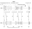
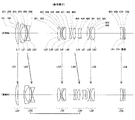
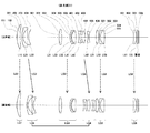
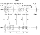
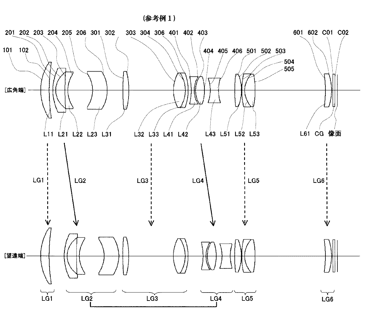
以下、具体的な数値実施例について、本発明を説明する。以下の第1実施例、第2実施例、参考例1−4のズームレンズでは拡大側から順に、全体で正の屈折力を有する第1レンズ群(各図におけるレンズ群名称LG1)、全体で負の屈折力を有する第2レンズ群(レンズ群名称LG2)、全体で正の屈折力を有する第3レンズ群(レンズ群名称LG3)、全体で負の屈折力を有する第4レンズ群(レンズ群名称LG4)及び全体で正の屈折力を有する第5レンズ群(レンズ群名称LG5)から構成され、前記第1レンズ群LG1は、正レンズ(レンズ名称をL11、拡大側面の面番号を101、縮小側面の面番号を102とする)1枚にて構成され、前記第2レンズ群LG2は、最も拡大側に、拡大側に凸のメニスカス形状の負レンズ(レンズ名称をL21、拡大側面の面番号を201、縮小側面の面番号を202とする)を配置し、全体で少なくとも二枚の負レンズを含む二乃至三枚のレンズにて構成され(L21以降順次レンズ名称をL22、L23などとし、面番号を順次203、204、205、206などとする)、前記第3レンズ群LG3は、最も拡大側に正レンズ(レンズ名称をL31、拡大側面の面番号を301、縮小側面の面番号を302とする)を配置し、全体で二枚の正レンズ及び一枚の負レンズにて構成され(L31以降順次レンズ名称をL32、L33などとし、面番号を順次303、304、305、306などとし、接合面の場合には重なる後の面番号を欠番とする)、前記第4レンズ群LG4は、拡大側から順に負レンズ(レンズ名称をL41、拡大側面の面番号を401、縮小側面の面番号を402とする)、正レンズ(レンズ名称をL42、拡大側面の面番号を403、縮小側面の面番号を404とする)、及び負レンズ(レンズ名称をL43、拡大側面の面番号を405、縮小側面の面番号を406とする)を配して構成され、前記第5レンズ群LG5は、拡大側から順に正レンズ(レンズ名称をL51、拡大側面の面番号を501、縮小側面の面番号を502とする)、負レンズ(レンズ名称をL52、拡大側面の面番号を503、縮小側面の面番号を504とする)及び正レンズ(レンズ名称をL53、拡大側面は接合のため面番号を同じく504、縮小側面の面番号を505とする)を配して構成されており、前記第5レンズ群LG5の縮小側には、大きな空気間隔を設け、その後に照明光学系との関連において第6レンズ群(レンズ群名称LG6)を、正レンズ(レンズ名称をL61、拡大側面の面番号を601、縮小側面の面番号を602とする)にて構成しても良く、続いて前記第6レンズ群LG6の縮小側とライトバルブ面との間には僅かな空気間隔をおいて配置されるDMD等のライトバルブの構成部品であるカバーガラスCG(拡大側面をC01、縮小側面をC02)を配置し構成される。広角端から望遠端への変倍動作は、前記第1レンズ群LG1、前記第3レンズ群LG3及び前記第5レンズ群LG5は変倍動作中固定されており、前記第2レンズ群LG2及び前記第4レンズ群LG4は拡大側から縮小側方向へ一体として光軸に沿って移動させ変倍を行う。
Hereinafter, the present invention will be described with respect to specific numerical examples. In the zoom lenses of the following first example , second example , and reference example 1-4 , in order from the magnification side, the first lens group having a positive refractive power as a whole (lens group name LG1 in each drawing), as a whole A second lens group (lens group name LG2) having negative refractive power, a third lens group (lens group name LG3) having positive refractive power as a whole, and a fourth lens group (lens having negative refractive power as a whole) And a fifth lens group (lens group name LG5) having a positive refractive power as a whole. The first lens group LG1 is a positive lens (lens name is L11, and the surface number of the enlarged side surface is 101). The second lens group LG2 has a meniscus-shaped negative lens (lens name L21, which is convex on the enlargement side, lens name on the enlargement side).
[参考例1]
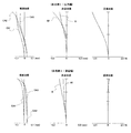
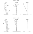
本発明のズームレンズの参考例1について数値例を表1に示す。また図1は、そのレンズ構成図、図2はその諸収差図である。
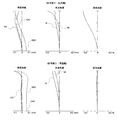
表中の上段で、fはズームレンズ全系の焦点距離、FnoはFナンバー、2ωはズームレンズの全画角を表し、dと括弧付の数値で表している、例えばd(102)であるが、これは102面が変倍に伴い空気間隔が変化する面であり、その変化する数値を表すものである。また下段のrは曲率半径、dはレンズ厚またはレンズ間隔、ndはd線に対する屈折率、νdはd線のアッベ数を示す。諸収差図中の球面収差図におけるCA1、CA2、CA3はそれぞれCA1=550nm、CA2=450nm、CA3=620nmの波長における収差曲線である。非点収差図におけるSはサジタル、Mはメリディオナルを示している。また、全般に亘り特別に記載のない限り、諸値の計算に使用している波長はCA1=550.0nmである。また、物体及び像の関係は101面からの物体距離を1700mmとした合焦状態を表しているものとする。
[ Reference Example 1]
Table 1 shows the numerical example with Reference Example 1 of the zoom lens of the present invention. FIG. 1 is a diagram showing the lens configuration, and FIG. 2 is a diagram showing various aberrations thereof.
In the upper part of the table, f represents the focal length of the entire zoom lens system, Fno represents the F number, 2ω represents the entire angle of view of the zoom lens, and is represented by d and parenthesized numerical values, for example, d (102). However, this is the surface on which the air space changes with zooming, and represents the changing numerical value. In the lower row, r is the radius of curvature, d is the lens thickness or lens interval, nd is the refractive index with respect to the d-line, and νd is the Abbe number of the d-line. CA1, CA2, and CA3 in the spherical aberration diagrams in the various aberration diagrams are aberration curves at wavelengths of CA1 = 550 nm, CA2 = 450 nm, and CA3 = 620 nm, respectively. In the astigmatism diagram, S indicates sagittal and M indicates meridional. In addition, unless otherwise specified throughout, the wavelength used for calculation of various values is CA1 = 550.0 nm. The relationship between the object and the image represents a focused state where the object distance from the 101 plane is 1700 mm.
[参考例2]
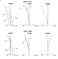
本発明のズームレンズの参考例2について数値例を表2に示す。また図3は、そのレンズ構成図、図4はその諸収差図である。
[ Reference Example 2]
Table 2 shows the numerical example with the reference example 2 of the zoom lens of the present invention. FIG. 3 is a diagram showing the lens configuration, and FIG. 4 is a diagram showing various aberrations thereof.
[参考例3]
本発明のズームレンズの参考例3について数値例を表3に示す。また図5は、そのレンズ構成図、図6はその諸収差図である。
[ Reference Example 3]
Table 3 shows the numerical example with the reference example 3 of the zoom lens of the present invention. FIG. 5 is a diagram showing the lens configuration, and FIG. 6 is a diagram showing various aberrations.
[実施例1]
本発明のズームレンズの第1実施例について数値例を表4に示す。また図7は、そのレンズ構成図、図8はその諸収差図である。
[Example 1 ]
Table 4 shows numerical examples of the first embodiment of the zoom lens according to the present invention. FIG. 7 is a diagram showing the lens configuration, and FIG. 8 is a diagram showing various aberrations.
[実施例2]
本発明のズームレンズの第2実施例について数値例を表5に示す。また図9は、そのレンズ構成図、図10はその諸収差図である。
[Example 2 ]
Table 5 shows numerical examples of the second embodiment of the zoom lens according to the present invention. FIG. 9 is a lens configuration diagram, and FIG. 10 is a diagram showing various aberrations.
[参考例4]
本発明のズームレンズの参考例4について数値例を表6に示す。また図11は、そのレンズ構成図、図12はその諸収差図である。
[Reference Example 4 ]
Table 6 shows numerical examples of Reference Example 4 of the zoom lens according to the present invention. FIG. 11 is a diagram showing the lens configuration, and FIG. 12 is a diagram showing various aberrations.
次に第1実施例、第2実施例、参考例1−4に関して条件式(1)から条件式(15)に対応する値を、まとめて表7に示す。 Next, Table 7 collectively shows values corresponding to the conditional expressions (1) to (15) regarding the first example , the second example , and the reference example 1-4 .
表7から明らかなように、第1実施例、第2実施例、参考例1−4に関する数値は条件式(1)から条件式(15)の条件式を満足しているとともに、各実施例における収差図からも明らかなように、各収差とも良好に補正されている。 As is clear from Table 7, the numerical values related to the first example , the second example , and the reference example 1-4 satisfy the conditional expressions (1) to (15), and each example. As is apparent from the aberration diagrams in FIG. 6, each aberration is corrected well.
Claims (7)
(1) −1.2 ≦ fw / fII ≦ −0.85
(2) −0.95 ≦ mIIIw ≦ −0.7
(3) TL / fw ≦ 8.0
(4) 1.75 ≦ bw / fw
ただし、
fw :広角端におけるレンズ全系の合成焦点距離
(第1レンズ群の最も拡大側の面からの物体距離1700mmに合焦の状態)
fII :第2レンズ群の合成焦点距離
mIIIw:広角端における第3レンズ群の合成倍率
TL :第1レンズ群の最も拡大側の面から像面までの距離
(ただし、第1レンズ群の最も拡大側の面からの物体距離1700mmに合焦の状態であり、第5レンズ群の最も縮小側面から像面までは空気換算距離)
bw :第5レンズ群の最も縮小側の面から像面までの距離
(ただし、第1レンズ群の最も拡大側の面からの物体距離1700mmに合焦の状態であり、第5レンズ群の最も縮小側面から像面までは空気換算距離) In order from the magnifying side, a first lens group having an overall positive refractive power, a second lens group having an overall negative refractive power, a third lens group having an overall positive refractive power, and an overall negative refractive power And a fifth lens group having a positive refractive power as a whole, and the first lens group, the third lens group, and the fifth lens group at the time of zooming from the wide-angle end to the telephoto end are The second lens group and the fourth lens group are moved integrally along the optical axis from the enlargement side to the reduction side direction, and the second lens group is moved during the magnification change operation. The following conditional expression (1) is satisfied with respect to power, the following conditional expression (2) is satisfied with respect to the magnification at the wide-angle end of the third lens group fixed during zooming, and the overall size of the optical system satisfies the following condition Set to the reduction side of the fifth lens group, satisfying equation (3) Zoom lens, characterized in that it satisfies the following conditional expression (4) with respect to space.
(1) -1.2 ≦ f w / f II ≦ -0.85
(2) -0.95 ≤ m IIIw ≤ -0.7
(3) TL / f w ≦ 8.0
(4) 1.75 ≦ b w / f w
However,
f w : Combined focal length of the entire lens system at the wide-angle end (focusing on an object distance of 1700 mm from the most magnified surface of the first lens group)
f II: a second lens unit of the composite focal length m III W: Synthesis magnification of the third lens group at the wide-angle end TL: distance from the closest to the magnification side surface of the first lens group to the image plane (provided that the first lens group The object distance is 1700 mm from the most magnified surface, and the distance from the most reduced side surface to the image surface of the fifth lens group is the air equivalent distance)
b w: distance between the most reduction side surface of the fifth lens group to the image plane (where a state of focusing on an object distance 1700mm between the most magnification side surface of the first lens group, the fifth lens group ( Air conversion distance from the most reduced side to the image plane )
(5) −0.5 ≦ fw / fII1 ≦ −0.45
(6) 0.85 ≦ fw / rII2 ≦ 1.2
ただし、
fII1:第2レンズ群において最も拡大側に配置されるレンズの焦点距離
rII2:第2レンズ群において最も拡大側に配置されるレンズの縮小側面の曲率半径 2. The zoom lens according to claim 1, wherein the second lens group includes, on the most enlargement side, a lens having a convex meniscus shape on the enlargement side and having negative refractive power (hereinafter referred to as a negative lens). Consists of two to three lenses including one negative lens, the following conditional expression (5) is satisfied with respect to the power of the negative lens arranged on the most magnified side, and the following conditional expression regarding the characteristics of the shape of the reduction side surface (6) is satisfied.
(5) −0.5 ≦ f w / f II1 ≦ −0.45
(6) 0.85 ≦ f w / r II2 ≦ 1.2
However,
f II1 : Focal length r II2 of the lens arranged closest to the magnification side in the second lens group: Radius of curvature of the reduction side surface of the lens arranged closest to the magnification side in the second lens group
(7) 0.2 ≦ fw / fIII1 ≦ 0.46
(8) 42 ≦|vIII2 − vIII3|
ただし、
fIII1:第3レンズ群において最も拡大側に配置されるレンズの焦点距離
vIII2:第3レンズ群の拡大側から二番目に配置されるレンズのアッベ数
vIII3:第3レンズ群の拡大側から三番目に配置されるレンズのアッベ数 2. The zoom lens according to claim 1, wherein the third lens group includes a positive lens disposed closest to the magnifying side, and includes a total of two positive lenses and one negative lens, and is disposed closest to the magnifying side. The following conditional expression (7) is satisfied with respect to the power of the positive lens, and the relationship between the dispersion characteristics of the lenses arranged second to third from the magnification side satisfies the following conditional expression (8). Features.
(7) 0.2 ≦ f w / f III1 ≦ 0.46
(8) 42 ≦ | v III2 −v III3 |
However,
f III1: the most focal length of the lens disposed on the magnification side in the third lens group v III2: third Abbe number of the lens element which is disposed second from the enlargement side of the lens group v III3: expansion side of the third lens group Abbe number of the lens arranged third from
(9) −0.95 ≦ fw / fIV ≦ −0.65
(10) 0.75 ≦ fw / fIV2 ≦ 1.25
(11) 8.0 ≦ VIVn − VIVp
(12) 1.72 ≦ nIVp
ただし、
fIV :第4レンズ群の合成焦点距離
fIV2:第4レンズ群において拡大側から二番目に配置されるレンズの焦点距離
VIVn:第4レンズ群を構成する負レンズのアッベ数の平均値
VIVp:第4レンズ群を構成する正レンズのアッベ数の平均値
nIVp:第4レンズ群を構成する正レンズのd線における屈折率 2. The zoom lens according to claim 1, wherein the fourth lens group includes a negative lens, a positive lens, and a negative lens in order from the magnification side, and satisfies the following conditional expression (9) with respect to the power of the entire group: And the following conditional expression (10) is satisfied with respect to the power of the lens arranged second from the magnifying side, and the relationship between the dispersion characteristics of the negative lens and the positive lens constituting the conditional expression satisfies the following conditional expression (11): The refractive index of the positive lens constituting the lens satisfies the following conditional expression (12).
(9) −0.95 ≦ f w / f IV ≦ −0.65
(10) 0.75 ≦ f w / f IV2 ≦ 1.25
(11) 8.0 ≦ V IVn −V IVp
(12) 1.72 ≦ n IVp
However,
f IV : Combined focal length f IV2 of the fourth lens group: Focal length V IVn of the lens arranged second from the magnification side in the fourth lens group: Average value of Abbe number of the negative lens constituting the fourth lens group V IVp : Average value of Abbe numbers of positive lenses constituting the fourth lens group n IVp : Refractive index at d-line of the positive lenses constituting the fourth lens group
(13) 0.6 ≦ fw / fV ≦ 0.75
(14) 25 ≦ VVp − VVn
(15) 1.78 ≦ nVn
ただし、
fV :第5レンズ群の合成焦点距離
VVp :第5レンズ群を構成する正レンズのアッベ数
VVn :第5レンズ群を構成する負レンズのアッベ数
nVn :第5レンズ群を構成する負レンズのd線における屈折率 2. The zoom lens according to claim 1, wherein the fifth lens group includes a positive lens, a negative lens, and a positive lens in order from the magnification side, and satisfies the following conditional expression (13) with respect to the power of the entire group: And the relationship between the dispersion characteristics of the positive lens and the negative lens constituting the lens satisfies the following conditional expression (14), and the refractive index of the negative lens constituting the lens satisfies the following conditional expression (15). And
(13) 0.6 ≦ f w / f V ≦ 0.75
(14) 25 ≤ V Vp -V Vn
(15) 1.78 ≦ n Vn
However,
f V : Composite focal length of the fifth lens group V Vp : Abbe number of the positive lens constituting the fifth lens group V Vn : Abbe number of the negative lens constituting the fifth lens group n Vn : Constructing the fifth lens group Refractive index of d-line of negative lens
Priority Applications (1)
| Application Number | Priority Date | Filing Date | Title |
|---|---|---|---|
| JP2009220334A JP5504792B2 (en) | 2009-09-25 | 2009-09-25 | Zoom lens and projection display device |
Applications Claiming Priority (1)
| Application Number | Priority Date | Filing Date | Title |
|---|---|---|---|
| JP2009220334A JP5504792B2 (en) | 2009-09-25 | 2009-09-25 | Zoom lens and projection display device |
Publications (2)
| Publication Number | Publication Date |
|---|---|
| JP2011069957A JP2011069957A (en) | 2011-04-07 |
| JP5504792B2 true JP5504792B2 (en) | 2014-05-28 |
Family
ID=44015318
Family Applications (1)
| Application Number | Title | Priority Date | Filing Date |
|---|---|---|---|
| JP2009220334A Expired - Fee Related JP5504792B2 (en) | 2009-09-25 | 2009-09-25 | Zoom lens and projection display device |
Country Status (1)
| Country | Link |
|---|---|
| JP (1) | JP5504792B2 (en) |
Families Citing this family (3)
| Publication number | Priority date | Publication date | Assignee | Title |
|---|---|---|---|---|
| US9703081B2 (en) | 2012-05-15 | 2017-07-11 | Ricoh Company, Ltd. | Projection zoom lens and projector |
| JP7643852B2 (en) * | 2020-09-29 | 2025-03-11 | 株式会社タムロン | Zoom lens and imaging device |
| CN114924380B (en) * | 2022-04-29 | 2023-08-04 | 歌尔光学科技有限公司 | Optical projection system and electronic equipment |
Family Cites Families (6)
| Publication number | Priority date | Publication date | Assignee | Title |
|---|---|---|---|---|
| JPS5833529B2 (en) * | 1978-09-12 | 1983-07-20 | 旭光学工業株式会社 | Optically corrected variable focal length lens system |
| JP3155884B2 (en) * | 1993-07-14 | 2001-04-16 | キヤノン株式会社 | Zoom lens |
| JP2007171456A (en) * | 2005-12-21 | 2007-07-05 | Tamron Co Ltd | Bent zoom lens |
| JP4867383B2 (en) * | 2006-02-15 | 2012-02-01 | コニカミノルタオプト株式会社 | Variable magnification optical system |
| JP4904842B2 (en) * | 2006-02-17 | 2012-03-28 | 株式会社ニコン | Zoom lens having anti-vibration function and image pickup apparatus having the same |
| JP5006634B2 (en) * | 2006-12-20 | 2012-08-22 | キヤノン株式会社 | Zoom lens and imaging apparatus having the same |
-
2009
- 2009-09-25 JP JP2009220334A patent/JP5504792B2/en not_active Expired - Fee Related
Also Published As
| Publication number | Publication date |
|---|---|
| JP2011069957A (en) | 2011-04-07 |
Similar Documents
| Publication | Publication Date | Title |
|---|---|---|
| JP5152833B2 (en) | Projection zoom lens and projection display device | |
| JP5081045B2 (en) | Projection zoom lens and projection display device | |
| JP5090852B2 (en) | Projection lens and projection display device using the same | |
| JP5259353B2 (en) | Projection lens and projection display device using the same | |
| JP4616966B2 (en) | Projection zoom lens and projector apparatus | |
| CN201666968U (en) | Zoom lens for projection and projection type display device | |
| JP5560636B2 (en) | Zoom lens and projection display device using the same | |
| JP5118583B2 (en) | Projection lens and projection display device using the same | |
| JP2009186790A (en) | Projection lens and projection display device with the same | |
| JP4599071B2 (en) | Zoom lens and image projection apparatus having the same | |
| JP5009726B2 (en) | Projection lens and projection display device using the same | |
| JP2012088518A (en) | Optical correction type zoom lens and projection type display device using the same | |
| JP2009237031A (en) | Zoom lens and projector device | |
| JP2011069956A (en) | Zoom lens and projection type display device using the same | |
| JP5118582B2 (en) | Projection lens and projection display device using the same | |
| JP4551676B2 (en) | Zoom lens, image display device, imaging device | |
| JP5504792B2 (en) | Zoom lens and projection display device | |
| JP2013195627A (en) | Zoom lens and projection-type display device | |
| JP2001337275A (en) | Zoom lens and projection device using the same | |
| JP2007140429A (en) | Zoom lens | |
| JP2012211973A (en) | Zoom lens and projection type display device using the same | |
| JP5458773B2 (en) | Zoom lens and projection display device | |
| JP5479926B2 (en) | Projection lens and projection display device using the same | |
| JP5118584B2 (en) | Projection lens and projection display device using the same | |
| JP5560624B2 (en) | Zoom lens and projection display device |
Legal Events
| Date | Code | Title | Description |
|---|---|---|---|
| A621 | Written request for application examination |
Free format text: JAPANESE INTERMEDIATE CODE: A621 Effective date: 20120918 |
|
| A977 | Report on retrieval |
Free format text: JAPANESE INTERMEDIATE CODE: A971007 Effective date: 20130816 |
|
| A131 | Notification of reasons for refusal |
Free format text: JAPANESE INTERMEDIATE CODE: A131 Effective date: 20130910 |
|
| TRDD | Decision of grant or rejection written | ||
| A01 | Written decision to grant a patent or to grant a registration (utility model) |
Free format text: JAPANESE INTERMEDIATE CODE: A01 Effective date: 20140218 |
|
| A61 | First payment of annual fees (during grant procedure) |
Free format text: JAPANESE INTERMEDIATE CODE: A61 Effective date: 20140303 |
|
| R150 | Certificate of patent or registration of utility model |
Ref document number: 5504792 Country of ref document: JP Free format text: JAPANESE INTERMEDIATE CODE: R150 |
|
| LAPS | Cancellation because of no payment of annual fees |