JP5259353B2 - Projection lens and projection display device using the same - Google Patents
Projection lens and projection display device using the same Download PDFInfo
- Publication number
- JP5259353B2 JP5259353B2 JP2008296790A JP2008296790A JP5259353B2 JP 5259353 B2 JP5259353 B2 JP 5259353B2 JP 2008296790 A JP2008296790 A JP 2008296790A JP 2008296790 A JP2008296790 A JP 2008296790A JP 5259353 B2 JP5259353 B2 JP 5259353B2
- Authority
- JP
- Japan
- Prior art keywords
- lens
- projection
- cemented
- positive
- projection lens
- Prior art date
- Legal status (The legal status is an assumption and is not a legal conclusion. Google has not performed a legal analysis and makes no representation as to the accuracy of the status listed.)
- Expired - Fee Related
Links
Images


Classifications
-
- G—PHYSICS
- G02—OPTICS
- G02B—OPTICAL ELEMENTS, SYSTEMS OR APPARATUS
- G02B13/00—Optical objectives specially designed for the purposes specified below
- G02B13/04—Reversed telephoto objectives
-
- G—PHYSICS
- G02—OPTICS
- G02B—OPTICAL ELEMENTS, SYSTEMS OR APPARATUS
- G02B13/00—Optical objectives specially designed for the purposes specified below
- G02B13/22—Telecentric objectives or lens systems
-
- G—PHYSICS
- G02—OPTICS
- G02B—OPTICAL ELEMENTS, SYSTEMS OR APPARATUS
- G02B15/00—Optical objectives with means for varying the magnification
- G02B15/14—Optical objectives with means for varying the magnification by axial movement of one or more lenses or groups of lenses relative to the image plane for continuously varying the equivalent focal length of the objective
- G02B15/142—Optical objectives with means for varying the magnification by axial movement of one or more lenses or groups of lenses relative to the image plane for continuously varying the equivalent focal length of the objective having two groups only
- G02B15/1425—Optical objectives with means for varying the magnification by axial movement of one or more lenses or groups of lenses relative to the image plane for continuously varying the equivalent focal length of the objective having two groups only the first group being negative
Landscapes
- Physics & Mathematics (AREA)
- General Physics & Mathematics (AREA)
- Optics & Photonics (AREA)
- Lenses (AREA)
- Projection Apparatus (AREA)
Description
本発明は、液晶表示素子等のライトバルブからの表示情報等を拡大投写する投写レンズに関し、特に、フロント式の投写型表示装置に好適な投写レンズおよびこれを用いた投写型表示装置に関する。 The present invention relates to a projection lens that magnifies and projects display information from a light valve such as a liquid crystal display element, and more particularly to a projection lens suitable for a front projection display device and a projection display device using the projection lens.
近年、液晶表示素子やDMD表示素子等のライトバルブを用いた投写型表示装置が普及しつつある。特に、ライトバルブを3枚用いてRGB3原色の照明光に各々対応させ、個々のライトバルブで変調された光をプリズム等で合成し、投写レンズを介してスクリーンに画像を表示する構成をとるものが広く利用されている。 In recent years, projection display devices using light valves such as liquid crystal display elements and DMD display elements are becoming popular. In particular, three light valves are used to correspond to the three primary colors of RGB illumination light, and the light modulated by the individual light valves is combined by a prism or the like, and an image is displayed on a screen via a projection lens. Is widely used.
このような、3枚のライトバルブからの各変調光を色合成光学系で合成して投写するタイプの投写型表示装置に搭載される投写レンズでは、上述したように、色合成を行なうプリズム等を配置するため、また、熱的な問題を回避するため、大きなバックフォーカスが必要となる。さらに、色合成光学系では入射光の角度によって分光特性が変化するため、投写レンズは縮小側から見た入射瞳が十分遠方に位置するという特性、すなわちテレセントリック性を持つことが必要となる。また、明るいレンズであることと、ライトバルブの解像度に見合った収差補正が必要とされる。 In such a projection lens mounted on a projection display device that synthesizes and projects each modulated light from the three light valves by a color synthesis optical system, as described above, a prism that performs color synthesis, etc. A large back focus is required in order to arrange the lens and to avoid thermal problems. Furthermore, since the spectral characteristics change depending on the angle of incident light in the color synthesizing optical system, the projection lens needs to have a characteristic that the entrance pupil viewed from the reduction side is located far away, that is, telecentricity. In addition, the lens must be a bright lens, and aberration correction commensurate with the resolution of the light valve is required.
このような要求をある程度満足するようにしたものとしては、例えば下記特許文献1、2に記載のものが知られている。また、本願出願人としても、このような投写レンズを既に特許庁に対して開示している(下記特許文献3参照)。
As what satisfy | fills such a request | requirement to some extent, the thing of the following
これらの特許文献に記載のものは、いずれも画角が100度以上の広角レンズとされている。 All of those described in these patent documents are wide-angle lenses having an angle of view of 100 degrees or more.
ところで、投写型表示装置としては、投写レンズがスクリーンに対して鑑賞者と同じ側に配置され、投写レンズより出射される光を反射型のスクリーンに結像させるフロント式の装置と、投写レンズおよび鑑賞者がスクリーンを挟むように配置され、投写レンズより出射される光を透過型のスクリーンに結像させるリア式の装置とが知られている。 By the way, as a projection display device, a projection lens is disposed on the same side as the viewer with respect to the screen, and a front-type device that forms an image of light emitted from the projection lens on a reflection screen, a projection lens, There is known a rear-type device that is arranged so that a viewer sandwiches a screen and images light emitted from a projection lens on a transmissive screen.
このうちリア式の投写型表示装置では、例えばリアプロジェクションテレビのように、光源からスクリーンまでをキャビネットに収め、キャビネット前面に配設されたスクリーンに向けて、背面側に配された投写レンズから映像情報を担持した光を投射する構成がよく知られている。上記特許文献1〜3のものも、このようなリア式の投写型表示装置に搭載されることを想定したものである。 Among these, rear projection display devices, such as a rear projection television, house the light source to the screen in a cabinet, and project the image from the projection lens arranged on the back side toward the screen arranged in the front of the cabinet. A configuration for projecting light carrying information is well known. The above-mentioned patent documents 1 to 3 are also assumed to be mounted on such a rear projection display device.
しかしながら、このようなリア式に係る投写レンズでは、キャビネットの厚みを薄くする目的でレンズ系中に光軸を折り返すためのプリズムやミラーが配されており、光軸に沿ったレンズ全長が長くなるため、装置の空間的なサイズ自体がどうしても大きくなってしまう。したがって、上記公報記載の投写レンズをフロント式の投写型表示装置に用いた場合には、装置サイズのコンパクト化を図ることが出来ないという問題がある。 However, in such a rear projection lens, a prism and a mirror for folding the optical axis are arranged in the lens system for the purpose of reducing the thickness of the cabinet, and the total length of the lens along the optical axis becomes long. For this reason, the spatial size of the device itself is inevitably increased. Therefore, when the projection lens described in the above publication is used in a front projection display device, there is a problem that the size of the device cannot be reduced.
また、フロント式の投写型表示システム(表示装置及びスクリーンを含む)においては、リア式のものと比較して、該システムの設置スペースの広さに制限が設けられることも多いことから、表示装置からスクリーンまでのワーキングディスタンスを短くすることが要望されており、投写レンズの広画角化が要求されている。 In addition, in a front-type projection display system (including a display device and a screen), there are many cases where the space for installing the system is limited as compared with a rear-type display system. There is a demand for shortening the working distance from the screen to the screen, and a wider angle of view of the projection lens is required.
本発明はこのような事情に鑑みなされたもので、縮小側がテレセントリックに構成されるとともに、近年の投写レンズに好適なバックフォーカスを有する構成とされ、さらに、フロント式の投写型表示装置に係る投写レンズにも適用し得るように、レンズ系全体としてコンパクト化および広画角化を達成しうる高性能な投写レンズ、およびこのような投写レンズを用いた投写型表示装置を提供することを目的とする。 The present invention has been made in view of such circumstances. The reduction side is configured to be telecentric, has a back focus suitable for a recent projection lens, and further includes a projection according to a front type projection display device. An object of the present invention is to provide a high-performance projection lens that can achieve a compact size and a wide angle of view as a whole lens system so that it can be applied to a lens, and a projection display device using such a projection lens. To do.
本発明に係る投写レンズは、
拡大側から順に、負の屈折力を有する第1レンズ群と、正の屈折力を有する第2レンズ群とが配列され、縮小側が略テレセントリックに構成されてなる投写レンズであって、
前記第1レンズ群は、最も拡大側に、非球面レンズからなる第1のレンズを配してなり、
前記第2レンズ群は、最も拡大側に、絞りを内部または近傍に有する正レンズからなる第2のレンズを備えるとともに、非球面レンズを備えてなり、
前記絞りと前記第2レンズ群中の非球面レンズとの間に、2枚以上の負レンズと2面以上の接合面が配されてなり、
以下の条件式(1)、(2)を満足することを特徴とするものである。
0.10<f/f2−1<0.30 (1)
N2−1>1.75 (2)
ここで、
f:レンズ系全体の焦点距離
f2−1:前記第2のレンズの焦点距離
N2−1:前記第2のレンズの、d線に対する屈折率
The projection lens according to the present invention is
A projection lens in which a first lens group having a negative refractive power and a second lens group having a positive refractive power are arranged in order from the magnification side, and the reduction side is configured to be substantially telecentric,
The first lens group includes a first lens composed of an aspheric lens on the most enlarged side,
The second lens group includes, on the most enlargement side, a second lens composed of a positive lens having an aperture inside or in the vicinity thereof, and an aspheric lens.
Between the stop and the aspherical lens in the second lens group, two or more negative lenses and two or more cemented surfaces are arranged,
The following conditional expressions (1) and (2) are satisfied.
0.10 <f / f 2-1 <0.30 (1)
N2-1 > 1.75 (2)
here,
f: Focal length of the entire lens system f 2-1 : Focal length of the second lens N 2-1 : Refractive index of the second lens with respect to the d-line
また、前記第2レンズ群のレンズのうち、前記第2のレンズおよび前記非球面レンズを除くレンズが、下記条件式(3)、(4)のいずれかを満足することが好ましい。
N2p<1.55 (3)
N2n>1.73 (4)
ここで、
N2p:第2レンズ群中の正レンズの、d線に対する屈折率
N2n:第2レンズ群中の負レンズの、d線に対する屈折率
In addition, it is preferable that the lenses other than the second lens and the aspheric lens among the lenses of the second lens group satisfy any of the following conditional expressions (3) and (4).
N2p <1.55 (3)
N2n> 1.73 (4)
here,
N2p: refractive index with respect to d-line of positive lens in second lens group N2n: refractive index with respect to d-line of negative lens in second lens group
また、前記第2レンズ群中に、アッベ数(νd)が75以上とされた正レンズを2枚以上含むことが好ましい。 The second lens group preferably includes two or more positive lenses having an Abbe number (ν d ) of 75 or more.
また、前記第1レンズ群は、拡大側から順に、プラスチックよりなる非球面レンズと、拡大側に凸面を向けた2枚の負メニスカスレンズと、拡大側に凹面を向けた負レンズおよび縮小側に凸面を向けた正レンズよりなる接合レンズと、を配列してなることが好ましい。 The first lens group includes, in order from the magnification side, an aspheric lens made of plastic, two negative meniscus lenses having a convex surface on the magnification side, a negative lens having a concave surface on the magnification side, and a reduction side. It is preferable to arrange a cemented lens made of a positive lens having a convex surface.
また、前記第1レンズ群中の前記接合レンズを光軸方向に移動させてフォーカシングを行なうことが好ましい。 Further, it is preferable to perform focusing by moving the cemented lens in the first lens group in the optical axis direction.
また、前記第1レンズ群中の前記接合レンズは、以下の条件式(5)を満足することが好ましい。
|N1p−N1n|<0.1 (5)
ここで、
N1p:前記第1レンズ群中の前記接合レンズを構成する前記正レンズの、d線に対する屈折率
N1n:前記第1レンズ群中の前記接合レンズを構成する前記負レンズの、d線に対する屈折率
The cemented lens in the first lens group preferably satisfies the following conditional expression (5).
| N 1p −N 1n | <0.1 (5)
here,
N 1p : Refractive index of the positive lens constituting the cemented lens in the first lens group with respect to the d-line N 1n : Negative refractive index of the negative lens constituting the cemented lens in the first lens group with respect to the d-line Refractive index
また、前記第2レンズ群は、拡大側から順に、正レンズと、拡大側に凸面を向けた負のメニスカスレンズおよび両凸レンズよりなる接合レンズと、両凹レンズおよび両凸レンズよりなる接合レンズと、非球面レンズと、両凹レンズと両凸レンズよりなる接合レンズと、両凸レンズと、を配列してなることが好ましい。 The second lens group includes, in order from the magnifying side, a positive lens, a negative meniscus lens having a convex surface facing the magnifying side, a cemented lens composed of a biconvex lens, a cemented lens composed of a biconcave lens and a biconvex lens, It is preferable to arrange a spherical lens, a cemented lens composed of a biconcave lens and a biconvex lens, and a biconvex lens.
さらに、本発明に係る投写型表示装置は、光源と、ライトバルブと、該光源からの光束を該ライトバルブへ導く照明光学部と、本発明に係る上記投写レンズとを備え、前記光源からの光束を前記ライトバルブで光変調し、前記投写レンズによりスクリーンに投写することを特徴とするものである。 Furthermore, a projection display device according to the present invention includes a light source, a light valve, an illumination optical unit that guides a light beam from the light source to the light valve, and the projection lens according to the present invention. The light beam is modulated by the light valve and projected onto the screen by the projection lens.
本発明の投写レンズは、上記構成を備えたことにより、近年の投写レンズに好適なバックフォーカスを有しつつ、フロント式の投写型表示装置に係る投写レンズにも適用し得るように、レンズ系全体としてコンパクト化および広画角化を達成しうる高解像度な投写レンズとすることができる。 Since the projection lens of the present invention has the above-described configuration, the lens system has a back focus suitable for a recent projection lens, and can also be applied to a projection lens for a front projection display device. As a whole, a high-resolution projection lens that can achieve a compact size and a wide angle of view can be obtained.
特に、条件式(1)、(2)を同時に満足するように構成したことにより、レンズ系のコンパクト化を達成しつつ、球面収差や像面湾曲を始めとする諸収差を良好なものとすることができる。 In particular, by satisfying the conditional expressions (1) and (2), the lens system can be made compact, and various aberrations including spherical aberration and field curvature can be improved. be able to.
また、本発明の投写型表示装置は、本発明の投写レンズを用いていることにより、フロント式の投写型表示装置にも適用し得るように、コンパクトなものとすることができる。 Further, the projection display device of the present invention can be made compact by using the projection lens of the present invention so that it can be applied to a front projection display device.
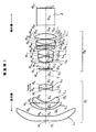
以下、本発明の実施形態について図面を用いて説明する。図1は本実施形態に係る投写レンズを示すものであり、後述する実施例1のレンズ構成図である。このレンズを本実施形態の代表として、以下に説明する。なお、図中Zは光軸を表している。 Hereinafter, embodiments of the present invention will be described with reference to the drawings. FIG. 1 shows a projection lens according to this embodiment, and is a lens configuration diagram of Example 1 to be described later. This lens will be described below as a representative of this embodiment. In the figure, Z represents the optical axis.
本実施形態の投写レンズは、拡大側から順に、負の屈折力を有する第1レンズ群G1と、正の屈折力を有する第2レンズ群G2とが配列されてなり、縮小側が略テレセントリックとされている。 Projection lens of this embodiment, in order from the magnification side, a first lens group G 1 having a negative refracting power and is the second lens group G 2 and the sequence having a positive refractive power, a substantially telecentric reduction side It is said that.
また、第1レンズ群G1は、最も拡大側に、非球面レンズからなる第1のレンズ(第1レンズL1)を配してなる。
また、第2レンズ群G2は、最も拡大側に、正レンズからなる第2のレンズ(各実施例のものでは第6レンズL6)を備えており、その正レンズの内部または近傍に絞りSが配されている。また、第2レンズ群G2は、非球面レンズを備えてなる。
In addition, the first lens group G 1 includes a first lens (first lens L 1 ) made of an aspheric lens on the most enlargement side.
The second lens group G 2 is the most magnification side (the ones of the examples the sixth lens L 6) a second lens comprising a positive lens includes a diaphragm in or near the positive lens S is arranged. The second lens group G 2 is composed includes an aspherical lens.
また、絞りSと第2レンズ群G2中の非球面レンズとの間には、2枚以上の負レンズと2面以上の接合面が配されてなる(下記実施例のものでは、実施例6のものを除き2枚の負レンズと2面の接合面を有し、実施例6のものは、2枚の負レンズと3面の接合面を有する)。 The diaphragm S and between the aspherical lens of the second lens group G 2, is intended to negative lens and two or more surfaces of the joint surface of two or more is disposed (in the examples below, Example Except 6 lenses, it has 2 negative lenses and 2 cemented surfaces, and the 6th embodiment has 2 negative lenses and 3 cemented surfaces).
また上記第1レンズ群G1は、より具体的には、拡大側から順に、プラスチックよりなる非球面レンズからなる第1レンズL1と、拡大側に凸面を向けた負メニスカスレンズからなる第2レンズL2および第3レンズL3と、拡大側に凹面を向けた負レンズからなる第4レンズL4および縮小側に凸面を向けた正レンズからなる第5レンズL5、よりなる接合レンズと、を配列してなることが好ましい。 Also the first lens group G 1 is more specifically in order from the magnification side, a second comprising a first lens L 1 composed of an aspheric lens made of plastic, a negative meniscus lens having a convex surface facing the magnification side A lens L 2 and a third lens L 3 , a fourth lens L 4 composed of a negative lens with a concave surface facing the enlargement side, and a fifth lens L 5 composed of a positive lens with a convex surface facing the reduction side, and a cemented lens Are preferably arranged.
また、上記第1レンズ群G1中の上記接合レンズを光軸Z方向に移動させてフォーカシングを行なうことが好ましい。 Further, it is preferable to perform focusing by moving the cemented lens of the first lens group G 1 in the optical axis Z direction.
一方、上記第2レンズ群G2は、より具体的には、拡大側から順に、正レンズからなる第6レンズL6と、拡大側に凸面を向けた負のメニスカスレンズからなる第7レンズL7と、両凸レンズからなる第8レンズL8と、両凹レンズからなる第9レンズL9と、両凸レンズからなる第10レンズL10と、非球面レンズからなる第11レンズL11と、両凹レンズからなる第12レンズL12と、両凸レンズからなる第13レンズL13と、両凸レンズからなる第14レンズL14と、を配列してなることが好ましい。この第2レンズ群G2においては、下記実施例に示すように、複数個の接合レンズが設けられており、これにより球面収差、色収差の補正を良好なものとすることができるとともに、レンズの製造効率を向上させることができる。 On the other hand, the second lens group G 2 includes, more specifically, in order from the magnification side, a sixth lens L 6, which is a positive lens, a seventh lens consisting of a negative meniscus lens having a convex surface on the enlargement side L 7, the eighth lens L 8, which is a biconvex lens, a ninth lens L 9, which is a biconcave lens, a tenth lens L 10 made of a biconvex lens, an eleventh lens L 11 made of a non-spherical lens, a biconcave lens a twelfth lens L 12 consisting of, a thirteenth lens L 13 is a biconvex lens, a fourteenth lens L 14 which is a biconvex lens, preferably formed by arranging the. In the second lens group G 2, as shown in the following examples, a plurality of cemented lens is provided, thereby the spherical aberration, with the correction of the chromatic aberration can be made favorable, lenses Manufacturing efficiency can be improved.
また、上記第2レンズ群G2中に、アッベ数(νd)が75以上とされた正レンズを2枚以上含む(下記実施例のものでは、第13レンズL13と第14レンズL14の2枚の正レンズが該当する)ことが好ましい。
Further, the during the second lens group G 2, it is intended to include positive lens Abbe number ([nu d) is 75 or more than two (in the examples below, the thirteenth lens L 13 and the
なお、図1の投写レンズでは、紙面右側より入射されライトバルブの画像表示面1において画像情報を与えられた光束が、色合成プリズム(各種フィルタ類を含む)2を介しこの投写レンズに入射され、この投写レンズにより紙面左側方向に拡大投写されるようになっている。図1には、見易さのため1枚の画像表示面1のみを記載しているが、投写型表示装置において、光源からの光束を色分離光学系により3原色光に分離し、各原色光用に3つのライトバルブを配設して、フルカラー画像を表示することが可能である。 In the projection lens of FIG. 1, a light beam incident from the right side of the paper and provided with image information on the image display surface 1 of the light valve enters the projection lens via a color synthesis prism (including various filters) 2. The projection lens enlarges and projects in the left direction of the paper. Although only one image display surface 1 is shown in FIG. 1 for ease of viewing, in the projection display device, a light beam from a light source is separated into three primary color lights by a color separation optical system. It is possible to display a full color image by arranging three light valves for light.
また、本実施形態のものは、以下の条件式(1)、(2)を満足するように構成されている。
0.10<f/f2−1<0.30 (1)
N2−1>1.75 (2)
ここで、
f:レンズ系全体の焦点距離
f2−1:第2のレンズ(実施例では第6レンズL6)の焦点距離
N2−1:第2のレンズ(実施例では第6レンズL6)の、d線に対する屈折率
Moreover, the thing of this embodiment is comprised so that the following conditional expressions (1) and (2) may be satisfied.
0.10 <f / f 2-1 <0.30 (1)
N2-1 > 1.75 (2)
here,
f: focal length of entire lens system f 2-1 : focal length of second lens (sixth lens L 6 in the embodiment) N 2-1 : second lens (sixth lens L 6 in the embodiment) , Refractive index for d-line
また、本実施形態のものは、上記第2レンズ群のレンズのうち、上記第2のレンズ(下記実施例では第6レンズL6)および上記非球面レンズ(下記実施例では第11レンズL11)を除くすべてのレンズが、下記条件式(3)、(4)のいずれかを満足することが好ましい。
N2p<1.55 (3)
N2n>1.73 (4)
ここで、
N2p:第2レンズ群G2中の正レンズの、d線に対する屈折率
N2n:第2レンズ群G2中の負レンズの、d線に対する屈折率
Further, in the present embodiment, among the lenses of the second lens group, the second lens (sixth lens L 6 in the following example) and the aspherical lens (eleventh lens L 11 in the following example) are used. It is preferable that all the lenses other than () satisfy either of the following conditional expressions (3) and (4).
N 2p <1.55 (3)
N 2n > 1.73 (4)
here,
N 2p: the positive lens in the second lens group G 2, the refractive index N 2n at the d-line: the negative lens in the second lens group G 2, the refractive index to the d-line
また、上記第1レンズ群G1中の接合レンズは、以下の条件式(5)を満足することが好ましい。
|N1p−N1n|<0.1 (5)
ここで、
N1p:第1レンズ群G1中の上記接合レンズを構成する正レンズの、d線に対する屈折率
N1n:第1レンズ群G1中の上記接合レンズを構成する負レンズの、d線に対する屈折率
Further, the cemented lens in the first lens group G 1 preferably satisfies the following conditional expression (5).
| N 1p −N 1n | <0.1 (5)
here,
N 1p: the positive lens constituting the cemented lens in the first lens group G 1, the refractive index N 1n the d-line: the negative lens constituting the cemented lens in the first lens group G 1, the d-line Refractive index
なお、上記の条件式のうち少なくとも(1)、(2)を満足することにより、前述した本発明の作用効果を得られるものである。 Note that, by satisfying at least (1) and (2) among the above conditional expressions, the above-described operational effects of the present invention can be obtained.
以下、上記条件式(1)〜(5)の各々の意義について説明する。 Hereinafter, the significance of each of the conditional expressions (1) to (5) will be described.
条件式(1)は、第2のレンズ(実施例では第6レンズL6)の焦点距離に対する全系の焦点距離fの値の範囲を示すものである。この下限値を下回るとレンズ全系が大型化するため、コンパクト化という要請に反し、一方、その上限値を上回ると球面収差の補正が困難になる。 Conditional expression (1) indicates the range of the value of the focal length f of the entire system with respect to the focal length of the second lens (sixth lens L 6 in the embodiment). If the lower limit is not reached, the entire lens system becomes larger, which is contrary to the demand for compactness. On the other hand, if the upper limit is exceeded, it is difficult to correct spherical aberration.
なお、この条件式(1)に替えて、下記条件式(1´)を満足するように構成することにより、上記条件式(1)の効果をより良好なものとすることができる。
0.15<f/f2−1<0.25 (1´)
In addition, it can replace with this conditional expression (1), and can make the effect of the said conditional expression (1) more favorable by comprising so that the following conditional expression (1 ') may be satisfied.
0.15 <f / f 2-1 <0.25 (1 ′)
条件式(2)は、上記第2のレンズ(実施例では第6レンズL6)の、d線に対する屈折率の下限を規定するものである。この下限値を下回ると、球面収差と像面湾曲の補正が困難になる。 Conditional expression (2) defines the lower limit of the refractive index with respect to the d-line of the second lens (sixth lens L 6 in the embodiment). Below this lower limit, it becomes difficult to correct spherical aberration and field curvature.
次に、条件式(3)は、第2レンズ群G2中の正レンズの、d線に対する屈折率の上限を規定するものであり、一方、条件式(4)は、第2レンズ群G2中の負レンズの、d線に対する屈折率の下限を規定するものである。条件式(3)および条件式(4)のいずれも満足しないと、球面収差および軸上・倍率の各色収差の補正を行うことが困難となる。 Next, the conditional expression (3), the positive lens in the second lens group G 2, which defines the upper limit of the refractive index at the d-line, whereas, the conditional expression (4), the second lens group G 2 defines the lower limit of the refractive index of the negative lens in FIG. If neither the conditional expression (3) nor the conditional expression (4) is satisfied, it becomes difficult to correct spherical aberration and chromatic aberrations on the axis and magnification.
なお、上記条件式(4)に替えて、下記条件式(4´)を満足するように構成することにより、球面収差および軸上・倍率の各色収差の補正を、より良好なものとすることができる。
N2n>1.75 (4´)
It should be noted that, in place of the conditional expression (4), the following conditional expression (4 ′) is satisfied so that the correction of spherical aberration and axial / magnification chromatic aberration can be improved. Can do.
N 2n > 1.75 (4 ′)
条件式(5)は、第1レンズ群G1中の上記接合レンズを構成する正レンズの、d線に対する屈折率N1pと、第1レンズ群G1中の上記接合レンズを構成する負レンズの、d線に対する屈折率N1nとの差の絶対値の範囲を規定するものである。すなわち、この接合レンズを構成する2つのレンズの形成材料の屈折率の差が0.1未満と小さいことが条件である。この範囲を外れると、フォーカス調整時の像面の変動が大きくなってしまう。 Condition (5) is a positive lens constituting the cemented lens in the first lens group G 1, the negative lens constituting the refractive index N 1p, the cemented lens in the first lens group G 1 to the d-line The range of the absolute value of the difference from the refractive index N 1n with respect to the d-line is defined. That is, the condition is that the difference in refractive index between the materials forming the two lenses constituting the cemented lens is as small as less than 0.1. Outside this range, the fluctuation of the image plane during focus adjustment becomes large.
また、第1レンズ群G1と第2レンズ群G2に含まれる各非球面の形状は、下記に示す非球面式により規定される。これらの非球面レンズにおいては、いずれか一方の面が非球面とされた場合であっても効果を得ることができるが、両面が非球面とされたレンズであることがより好ましい。 Each aspherical surface included first lens group G 1 and the second lens group G 2 is defined by the aspheric equation shown below. In these aspherical lenses, the effect can be obtained even when either one of the surfaces is aspherical, but it is more preferable that the both aspherical lenses are aspherical.
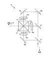
次に、本発明に係る投写型表示装置の実施形態について説明する。図17は本発明の一実施形態に係る投写型表示装置を示す概略図である。 Next, an embodiment of a projection display device according to the present invention will be described. FIG. 17 is a schematic view showing a projection display apparatus according to an embodiment of the present invention.
図17に示すように上記照明光学系10は、ライトバルブとしての透過型液晶パネル11a〜11cと、色分解のためのダイクロイックミラー12,13と、色合成のためのクロスダイクロイックプリズム14と、コンデンサレンズ16a〜16cと、全反射ミラー18a〜18cとを備えている。ダイクロイックミラー12の前段は図示を省略しているが白色光源が配されており、この光源からの白色光は照明光学部を介して、3つの色光光束(G光、B光、R光)にそれぞれ対応する液晶パネル11a〜11cに入射されて光変調され、図17に示す投写レンズによりスクリーン7に投写される。
As shown in FIG. 17, the illumination
以下、本発明に係る投写レンズの具体的な実施例について説明する。なお、各実施例において、互いに同様の構成を有し、同様の作用効果をなす部材については同一の符号を付している。 Specific examples of the projection lens according to the present invention will be described below. In addition, in each Example, the same code | symbol is attached | subjected about the member which has the mutually same structure and makes the same effect.
<実施例1>
図1に示すように、実施例1に係る投写レンズは、拡大側から順に、負の屈折力を有する第1レンズ群G1と、正の屈折力を有する第2レンズ群G2とが配列されてなり、縮小側が略テレセントリックとされている。
<Example 1>
1, the projection lens according to Example 1, in order from the magnification side, a first lens group G 1 having a negative refractive power, positive second lens group G 2 and the sequence having a refractive power As a result, the reduction side is substantially telecentric.
また、第1レンズ群G1は、第1レンズ群G1は、拡大側から順に、屈折力の小さい非球面レンズよりなる第1レンズL1と、縮小側に凹面を向けた負メニスカスレンズよりなる第2レンズL2および第3レンズL3と、両凹レンズからなる第4レンズL4と両凸レンズからなる第5レンズL5を接合してなる2枚接合レンズが配列されてなる。 The first lens group G 1, the first lens group G 1 includes, in order from the magnification side, a first lens L 1 made of a small aspherical lens having refractive power, a negative meniscus lens having a concave surface facing the reduction side The second lens L 2 and the third lens L 3 , the fourth lens L 4 composed of a biconcave lens, and the fifth lens L 5 composed of a biconvex lens are arrayed.
一方、第2レンズ群G2は、絞り3が内部に配された、拡大側に凸面を向けた平凸レンズよりなる第6レンズL6と、縮小側に凹面を向けた負メニスカスレンズよりなる第7レンズL7と、両凸レンズからなる第8レンズL8と、両凹レンズからなる第9レンズL9と、両凸レンズからなる第10レンズL10と、屈折力の小さい非球面レンズよりなる第11レンズL11と、両凹レンズからなる第12レンズL12と、両凸レンズからなる第13レンズL13および第14レンズL14が配列されてなる。
On the other hand, the second lens group G 2 includes,
なお、第2レンズ群G2における、第7レンズL7と第8レンズL8、および第9レンズL9と第10レンズL10は、各々互いに接合されて2枚接合レンズを構成する。 Incidentally, in the second lens group G 2, and the seventh lens L 7 eighth lens L 8, and a ninth lens L 9 tenth lens L 10 constitute each joined together by two cemented lenses.
なお、この投写レンズは縮小側にテレセントリックとなるように構成されている。 The projection lens is configured to be telecentric on the reduction side.
また、第1レンズ群G1中の、第4レンズL4と第5レンズL5を接合してなる接合レンズを光軸Z方向に移動させてフォーカシングを行なうように構成されている。 Further, in the first lens group G 1 is configured to the fourth lens L 4 and the fifth lens L 5 cemented lens formed by cementing a is moved in the direction of the optical axis Z to perform focusing.
実施例1に係る投写レンズは、上記条件式(1)〜(5)、(1´)、(4´)を全て満足するように構成されている。 The projection lens according to Example 1 is configured to satisfy all of the conditional expressions (1) to (5), (1 ′), and (4 ′).
また、図1には、ライトバルブの画像表示面1および色合成プリズム(各種フィルタ類を含む)2が示されている。 FIG. 1 also shows an image display surface 1 and a color synthesis prism (including various filters) 2 of the light valve.
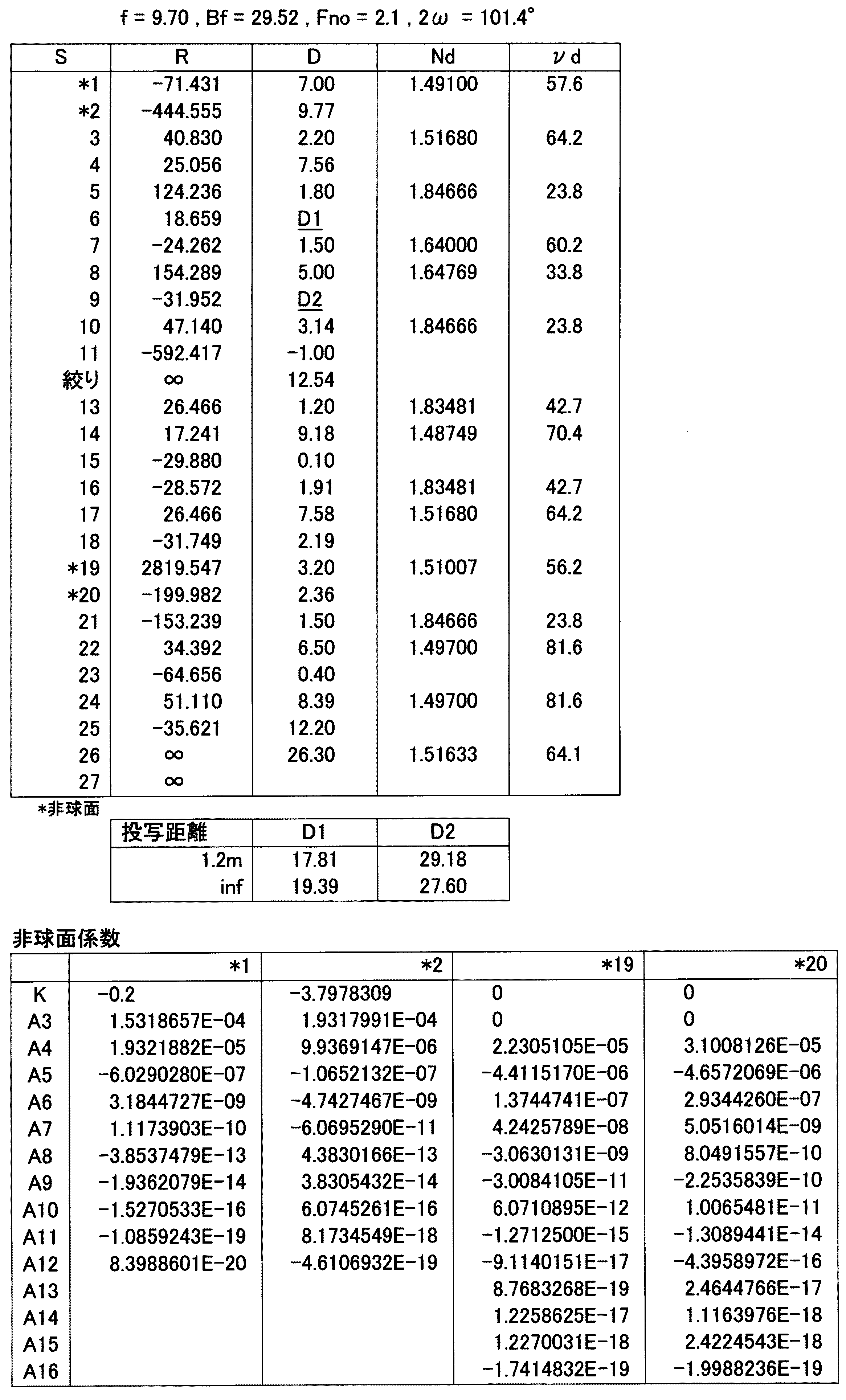
実施例1における全系の焦点距離f(mm)、バックフォーカスBf(mm)、FナンバFno.、画角2ωの各数値を表1の最上段に示す。 The focal length f (mm), back focus Bf (mm), F number Fno. The numerical values of the angle of view 2ω are shown at the top of Table 1.
また、実施例1に係る投写レンズの各レンズ面の曲率半径R(mm)、各レンズの中心厚および各レンズ間の空気間隔(以下「軸上面間隔」と称す)D(mm)、各レンズのd線における屈折率Ndおよび各レンズのd線におけるアッベ数νdの値を、表1の上段に示す。なお、表1および以下の表において面番号の数字は拡大側からの順番を表すものであり、面番号の左側に*印が付された面は非球面とされている。実施例1および以下の実施例2〜8において、これらの非球面の曲率半径Rは、各表において光軸Z上での曲率半径Rの値として示しているが、対応するレンズ構成図においては図面を見やすくするため、引出線は必ずしも光軸Zとの交点から引き出されていないものがある。 Further, the radius of curvature R (mm) of each lens surface of the projection lens according to Example 1, the center thickness of each lens, and the air space between each lens (hereinafter referred to as “axial upper surface distance”) D (mm), each lens Table 1 shows the values of the refractive index N d at the d-line and the Abbe number ν d at the d-line of each lens. In Table 1 and the following table, the surface number numbers indicate the order from the enlargement side, and the surface marked with * on the left side of the surface number is an aspheric surface. In Example 1 and Examples 2 to 8 below, the curvature radius R of these aspheric surfaces is shown as the value of the curvature radius R on the optical axis Z in each table, but in the corresponding lens configuration diagram. In order to make the drawing easy to see, there are some leader lines that are not necessarily drawn from the intersection with the optical axis Z.
また、表1の中段には、所定の投写距離(1.2m、無限遠)においてフォーカシングされた際の面間隔D1、D2の数値を示す。
なお、表1の下段には各非球面に対応する各定数K,A3〜A12の値が示されている。
The middle part of Table 1 shows numerical values of the surface distances D 1 and D 2 when focusing is performed at a predetermined projection distance (1.2 m, infinity).
In the lower part of Table 1, values of constants K, A 3 to A 12 corresponding to the respective aspheric surfaces are shown.
なお、実施例1において各条件式(1)〜(5)、(1´)、(4´)に対応する値は、後述する表9に示すとおりであり、条件式(1)〜(5)、(1´)、(4´)は全て満足されている。 In Example 1, values corresponding to the conditional expressions (1) to (5), (1 ′), and (4 ′) are as shown in Table 9 to be described later, and the conditional expressions (1) to (5) ), (1 ′), (4 ′) are all satisfied.
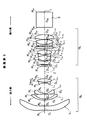
<実施例2>
実施例2に係る投写レンズの構成は、図2に示すとおりであり、基本的に実施例1に係る投写レンズと同様であるが、絞りSが、第6レンズL6の縮小側の面よりも、より縮小側に配されている点において、また、第6レンズL6が、拡大側に凸面を向けた正のメニスカスレンズとされている点において、実施例1に係る投写レンズと相違する。
<Example 2>
Structure of a projection lens according to Example 2 is as shown in FIG. 2 is similar to the projection lens according to basically as Example 1, a diaphragm S is, from the reduction side surface of the sixth lens L 6 However, the sixth lens L 6 is different from the projection lens according to the first embodiment in that the sixth lens L 6 is a positive meniscus lens having a convex surface facing the enlargement side. .
実施例2における全系の焦点距離f(mm)、バックフォーカスBf(mm)、FナンバFno.、画角2ωの各数値を表2の最上段に示す。
また、実施例2に係る投写レンズの各レンズ面の曲率半径R(mm)、軸上面間隔D(mm)、各レンズのd線における屈折率Ndおよび各レンズのd線におけるアッベ数νdの値を、表2の上段に示す。
The focal length f (mm), back focus Bf (mm), F number Fno. The numerical values of the angle of view 2ω are shown in the top row of Table 2.
Further, the radius of curvature R (mm) of each lens surface of the projection lens according to Example 2, the axial top surface distance D (mm), the refractive index N d of each lens at the d-line, and the Abbe number ν d of each lens at the d-line. The values of are shown in the upper part of Table 2.
また、表2の中段には、所定の投写距離(1.2m、無限遠)においてフォーカシングされた際の面間隔D1、D2の数値を示す。
なお、表2の下段には各非球面に対応する各定数K,A3〜A12の値が示されている。
The middle part of Table 2 shows numerical values of the surface distances D 1 and D 2 when focusing is performed at a predetermined projection distance (1.2 m, infinity).
In the lower part of Table 2, the values of the constants K, A 3 to A 12 corresponding to the aspheric surfaces are shown.
なお、実施例2において各条件式(1)〜(5)、(1´)、(4´)に対応する値は、後述する表9に示すとおりであり、条件式(1)〜(5)、(1´)、(4´)は全て満足されている。 In Example 2, values corresponding to the conditional expressions (1) to (5), (1 ′), and (4 ′) are as shown in Table 9 to be described later, and the conditional expressions (1) to (5) ), (1 ′), (4 ′) are all satisfied.
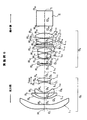
<実施例3>
実施例3に係る投写レンズの構成は、図3に示すとおりであり、基本的に実施例1に係る投写レンズと同様であるが、第6レンズL6が両凸レンズとされている点において、実施例1に係る投写レンズと相違する。
<Example 3>
The structure of a projection lens according to Example 3, is as shown in FIG. 3, is similar to the projection lens according to basically as Example 1, in that the sixth lens L 6 is a biconvex lens, This differs from the projection lens according to Example 1.
実施例3における全系の焦点距離f(mm)、バックフォーカスBf(mm)、FナンバFno.、画角2ωの各数値を表3の最上段に示す。
また、実施例3に係る投写レンズの各レンズ面の曲率半径R(mm)、軸上面間隔D(mm)、各レンズのd線における屈折率Ndおよび各レンズのd線におけるアッベ数νdの値を、表3の上段に示す。
The focal length f (mm) of the entire system, back focus Bf (mm), F number Fno. The numerical values of the angle of view 2ω are shown in the top row of Table 3.
Further, the radius of curvature R (mm) of each lens surface of the projection lens according to Example 3, the axial top surface distance D (mm), the refractive index N d of each lens at the d-line, and the Abbe number ν d of each lens at the d-line. The values of are shown in the upper part of Table 3.
また、表3の中段には、所定の投写距離(1.2m、無限遠)においてフォーカシングされた際の面間隔D1、D2の数値を示す。
なお、表3の下段には各非球面に対応する各定数K,A3〜A16の値が示されている。
The middle part of Table 3 shows numerical values of the surface distances D 1 and D 2 when focusing is performed at a predetermined projection distance (1.2 m, infinity).
In the lower part of Table 3, the values of the constants K, A 3 to A 16 corresponding to the respective aspheric surfaces are shown.
なお、実施例3において各条件式(1)〜(5)、(1´)、(4´)に対応する値は、後述する表9に示すとおりであり、条件式(1)〜(5)、(1´)、(4´)は全て満足されている。 In Example 3, values corresponding to the conditional expressions (1) to (5), (1 ′), and (4 ′) are as shown in Table 9 to be described later, and the conditional expressions (1) to (5) ), (1 ′), (4 ′) are all satisfied.
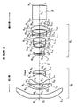
<実施例4>
実施例4に係る投写レンズの構成は、図4に示すとおりであり、基本的に実施例1に係る投写レンズと同様であるが、第6レンズL6が両凸レンズとされている点において、また、第7レンズL7が単独のレンズとされるとともに、第8レンズL8、第9レンズL9および第10レンズL10が順次接合されて3枚接合レンズを構成している点において、実施例1に係る投写レンズと相違する。
<Example 4>
The structure of a projection lens according to Example 4 is as shown in FIG. 4, it is similar to the projection lens according to basically as Example 1, in that the sixth lens L 6 is a biconvex lens, The seventh lens L 7 is a single lens, and the eighth lens L 8 , the ninth lens L 9 and the tenth lens L 10 are sequentially cemented to form a three-lens cemented lens. This differs from the projection lens according to Example 1.
実施例4における全系の焦点距離f(mm)、バックフォーカスBf(mm)、FナンバFno.、画角2ωの各数値を表4の最上段に示す。
また、実施例4に係る投写レンズの各レンズ面の曲率半径R(mm)、軸上面間隔D(mm)、各レンズのd線における屈折率Ndおよび各レンズのd線におけるアッベ数νdの値を、表4の上段に示す。
The focal length f (mm), back focus Bf (mm), F number Fno. The numerical values of the angle of view 2ω are shown in the top row of Table 4.
Further, the radius of curvature R (mm) of each lens surface of the projection lens according to Example 4, the axial top surface distance D (mm), the refractive index N d of each lens at the d-line, and the Abbe number ν d of each lens at the d-line. The values of are shown in the upper part of Table 4.
また、表4の中段には、所定の投写距離(1.2m、無限遠)においてフォーカシングされた際の面間隔D1、D2の数値を示す。
なお、表4の下段には各非球面に対応する各定数K,A3〜A16の値が示されている。
The middle part of Table 4 shows numerical values of the surface distances D 1 and D 2 when focusing is performed at a predetermined projection distance (1.2 m, infinity).
In the lower part of Table 4, the values of the constants K, A 3 to A 16 corresponding to the respective aspheric surfaces are shown.
なお、実施例4において各条件式(1)〜(5)、(1´)、(4´)に対応する値は、後述する表9に示すとおりであり、条件式(1)〜(5)、(1´)、(4´)は全て満足されている。 In Example 4, values corresponding to the conditional expressions (1) to (5), (1 ′), and (4 ′) are as shown in Table 9 to be described later, and the conditional expressions (1) to (5) ), (1 ′), (4 ′) are all satisfied.
<実施例5>
実施例5に係る投写レンズの構成は、図5に示すとおりであり、基本的に実施例1に係る投写レンズと同様であるが、第6レンズL6が両凸レンズとされている点において、また、第7レンズL7、第8レンズL8および第9レンズL9が順次接合されて3枚接合レンズを構成するとともに、第10レンズL10が単独のレンズとされている点において、実施例1に係る投写レンズと相違する。
<Example 5>
The structure of a projection lens according to Example 5, is as shown in FIG. 5 is similar to the projection lens according to basically as Example 1, in that the sixth lens L 6 is a biconvex lens, The seventh lens L 7 , the eighth lens L 8 and the ninth lens L 9 are sequentially cemented to form a three-lens cemented lens, and the tenth lens L 10 is a single lens. This differs from the projection lens according to Example 1.
実施例5における全系の焦点距離f(mm)、バックフォーカスBf(mm)、FナンバFno.、画角2ωの各数値を表5の最上段に示す。
また、実施例5に係る投写レンズの各レンズ面の曲率半径R(mm)、軸上面間隔D(mm)、各レンズのd線における屈折率Ndおよび各レンズのd線におけるアッベ数νdの値を、表5の上段に示す。
The focal length f (mm), back focus Bf (mm), F number Fno. The numerical values of the angle of view 2ω are shown in the top row of Table 5.
Further, the radius of curvature R (mm) of each lens surface of the projection lens according to Example 5, the axial top surface distance D (mm), the refractive index N d of each lens at the d-line, and the Abbe number ν d of each lens at the d-line. The values of are shown in the upper part of Table 5.
また、表5の中段には、所定の投写距離(1.2m、無限遠)においてフォーカシングされた際の面間隔D1、D2の数値を示す。
なお、表5の下段には各非球面に対応する各定数K,A3〜A16の値が示されている。
The middle part of Table 5 shows numerical values of the surface distances D 1 and D 2 when focusing is performed at a predetermined projection distance (1.2 m, infinity).
In the lower part of Table 5, the values of the constants K, A 3 to A 16 corresponding to the respective aspheric surfaces are shown.
なお、実施例5において各条件式(1)〜(5)、(1´)、(4´)に対応する値は、後述する表9に示すとおりであり、条件式(1)〜(5)、(1´)、(4´)は全て満足されている。 In Example 5, values corresponding to the conditional expressions (1) to (5), (1 ′), and (4 ′) are as shown in Table 9 to be described later, and the conditional expressions (1) to (5) ), (1 ′), (4 ′) are all satisfied.
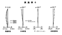
<実施例6>
実施例6に係る投写レンズの構成は、図6に示すとおりであり、基本的に実施例1に係る投写レンズと同様であるが、第6レンズL6が両凸レンズとされている点において、また、第7レンズL7、第8レンズL8、第9レンズL9および第10レンズL10が順次接合されて4枚接合レンズを構成する点において、実施例1に係る投写レンズと相違する。
<Example 6>
The structure of a projection lens according to Example 6, is as shown in FIG. 6 is similar to the projection lens according to basically as Example 1, in that the sixth lens L 6 is a biconvex lens, The seventh lens L 7 , the eighth lens L 8 , the ninth lens L 9, and the tenth lens L 10 are sequentially cemented to form a four-lens cemented lens, which is different from the projection lens according to the first embodiment. .
実施例6における全系の焦点距離f(mm)、バックフォーカスBf(mm)、FナンバFno.、画角2ωの各数値を表6の最上段に示す。
また、実施例6に係る投写レンズの各レンズ面の曲率半径R(mm)、軸上面間隔D(mm)、各レンズのd線における屈折率Ndおよび各レンズのd線におけるアッベ数νdの値を、表6の上段に示す。
The focal length f (mm), back focus Bf (mm), F number Fno. The numerical values of the angle of view 2ω are shown in the top row of Table 6.
Further, the radius of curvature R (mm) of each lens surface of the projection lens according to Example 6, the axial distance D (mm), the refractive index N d of each lens at the d-line, and the Abbe number ν d of each lens at the d-line. The values of are shown in the upper part of Table 6.
また、表6の中段には、所定の投写距離(1.2m、無限遠)においてフォーカシングされた際の面間隔D1、D2の数値を示す。
なお、表6の下段には各非球面に対応する各定数K,A3〜A16の値が示されている。
The middle part of Table 6 shows numerical values of the surface distances D 1 and D 2 when focusing is performed at a predetermined projection distance (1.2 m, infinity).
The lower part of Table 6 shows the values of the constants K, A 3 to A 16 corresponding to the aspheric surfaces.
なお、実施例6において各条件式(1)〜(5)、(1´)、(4´)に対応する値は、後述する表9に示すとおりであり、条件式(1)〜(5)、(1´)、(4´)は全て満足されている。 In Example 6, values corresponding to the conditional expressions (1) to (5), (1 ′), and (4 ′) are as shown in Table 9 to be described later, and the conditional expressions (1) to (5) ), (1 ′), (4 ′) are all satisfied.
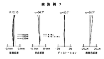
<実施例7>
実施例7に係る投写レンズの構成は、図7に示すとおりであり、基本的に実施例1に係る投写レンズと同様であるが、第6レンズL6が両凸レンズとされている点において、実施例1に係る投写レンズと相違する。
<Example 7>
The structure of a projection lens according to Example 7 is as shown in FIG. 7, it is similar to the projection lens according to basically as Example 1, in that the sixth lens L 6 is a biconvex lens, This differs from the projection lens according to Example 1.
実施例7における全系の焦点距離f(mm)、バックフォーカスBf(mm)、FナンバFno.、画角2ωの各数値を表7の最上段に示す。
また、実施例7に係る投写レンズの各レンズ面の曲率半径R(mm)、軸上面間隔D(mm)、各レンズのd線における屈折率Ndおよび各レンズのd線におけるアッベ数νdの値を、表7の上段に示す。
In Example 7, the focal length f (mm), back focus Bf (mm), F number Fno. The numerical values of the angle of view 2ω are shown in the top row of Table 7.
Further, the radius of curvature R (mm) of each lens surface of the projection lens according to Example 7, the axial distance D (mm), the refractive index N d of each lens at the d-line, and the Abbe number ν d of each lens at the d-line. The values of are shown in the upper part of Table 7.
また、表7の中段には、所定の投写距離(1.2m、無限遠)においてフォーカシングされた際の面間隔D1、D2の数値を示す。
なお、表7の下段には各非球面に対応する各定数K,A3〜A16の値が示されている。
The middle part of Table 7 shows numerical values of the surface distances D 1 and D 2 when focusing is performed at a predetermined projection distance (1.2 m, infinity).
In the lower part of Table 7, the values of the constants K, A 3 to A 16 corresponding to the respective aspheric surfaces are shown.
なお、実施例7において各条件式(1)〜(5)、(1´)、(4´)に対応する値は、後述する表9に示すとおりであり、条件式(1)〜(5)、(1´)、(4´)は全て満足されている。 In Example 7, values corresponding to the conditional expressions (1) to (5), (1 ′), and (4 ′) are as shown in Table 9 to be described later, and the conditional expressions (1) to (5) ), (1 ′), (4 ′) are all satisfied.
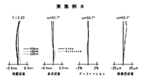
<実施例8>
実施例8に係る投写レンズの構成は、図8に示すとおりであり、基本的に実施例1に係る投写レンズと同様であるが、第6レンズL6が両凸レンズとされている点において、実施例1に係る投写レンズと相違する。
<Example 8>
The structure of a projection lens according to Example 8, is as shown in FIG. 8 is similar to the projection lens according to basically as Example 1, in that the sixth lens L 6 is a biconvex lens, This differs from the projection lens according to Example 1.
実施例8における全系の焦点距離f(mm)、バックフォーカスBf(mm)、FナンバFno.、画角2ωの各数値を表8の最上段に示す。
また、実施例8に係る投写レンズの各レンズ面の曲率半径R(mm)、軸上面間隔D(mm)、各レンズのd線における屈折率Ndおよび各レンズのd線におけるアッベ数νdの値を、表8の上段に示す。
In Example 8, the focal length f (mm) of the entire system, the back focus Bf (mm), the F number Fno. The numerical values of the angle of view 2ω are shown in the top row of Table 8.
Further, the radius of curvature R (mm) of each lens surface of the projection lens according to Example 8, the axial distance D (mm), the refractive index N d of each lens at the d-line, and the Abbe number ν d of each lens at the d-line. The values of are shown in the upper part of Table 8.
また、表8の中段には、所定の投写距離(1.2m、無限遠)においてフォーカシングされた際の面間隔D1、D2の数値を示す。
なお、表8の下段には各非球面に対応する各定数K,A3〜A16の値が示されている。
The middle part of Table 8 shows numerical values of the surface distances D 1 and D 2 when focusing is performed at a predetermined projection distance (1.2 m, infinity).
In the lower part of Table 8, values of constants K, A 3 to A 16 corresponding to the respective aspheric surfaces are shown.
なお、実施例8において各条件式(1)〜(5)、(1´)、(4´)に対応する値は、後述する表9に示すとおりであり、条件式(1)〜(5)、(1´)、(4´)は全て満足されている。 In Example 8, values corresponding to the conditional expressions (1) to (5), (1 ′), and (4 ′) are as shown in Table 9 to be described later, and the conditional expressions (1) to (5) ), (1 ′), (4 ′) are all satisfied.
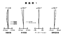
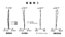
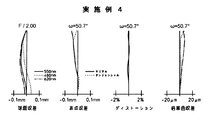
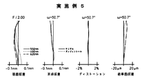
また、図9〜16は、実施例1〜8に係る投写レンズの諸収差(球面収差、非点収差、ディストーションおよび倍率色収差)を示す収差図である。これらの収差図において、ωは半画角を示し、球面収差の収差図には波長が550nm、460nmおよび620nmの光に対する収差曲線を示し、倍率色収差の収差図には波長が550nmの光に対する、460nmおよび620nmの光における収差曲線を示している。図9〜16に示すように、実施例1〜8に係る投写レンズは、歪曲収差や倍率色収差をはじめ各収差が良好に補正され、半画角50.7度以上、Fナンバ2.00〜2.30と、広角で明るい投写レンズとされている。また、十分なバックフォーカス(29.52〜30.31)を有する。さらに、各条件式が満足されており、コンパクトで高性能な投写レンズとされている。 9 to 16 are aberration diagrams showing various aberrations (spherical aberration, astigmatism, distortion and lateral chromatic aberration) of the projection lenses according to Examples 1 to 8. FIG. In these aberration diagrams, ω indicates a half angle of view, the aberration diagram of spherical aberration shows aberration curves for light with wavelengths of 550 nm, 460 nm, and 620 nm, and the aberration diagram of lateral chromatic aberration for light with a wavelength of 550 nm, The aberration curves for light at 460 nm and 620 nm are shown. As shown in FIGS. 9 to 16, in the projection lenses according to Examples 1 to 8, each aberration including distortion and lateral chromatic aberration is satisfactorily corrected, the half angle of view is 50.7 degrees or more, and the F number is 2.00. The projection lens is 2.30, which is a wide-angle and bright projection lens. Moreover, it has sufficient back focus (29.52-30.31). Furthermore, each conditional expression is satisfied, and the projection lens is compact and has high performance.
なお、本発明の投写レンズとしては、上記実施例のものに限られるものではなく種々の態様の変更が可能であり、例えば各レンズの曲率半径Rおよびレンズ間隔(もしくはレンズ厚)Dを適宜変更することが可能である。 The projection lens according to the present invention is not limited to the above-described embodiments, and various modifications can be made. For example, the curvature radius R and the lens interval (or lens thickness) D of each lens can be changed as appropriate. Is possible.
また、本発明の投写型表示装置としても、上記構成のものに限られるものではなく、本発明の投写レンズを備えた種々の装置構成が可能である。ライトバルブとしては、例えば、透過型または反射型の液晶表示素子や、傾きを変えることができる微小な鏡が略平面上に多数形成された微小ミラー素子(例えば、テキサス・インスツルメント社製のデジタルマイクロミラーデバイス)を用いることができる。また、照明光学系としても、ライトバルブの種類に対応した適切な構成を採用することができる。 Further, the projection display device of the present invention is not limited to the above-described configuration, and various device configurations including the projection lens of the present invention are possible. As the light valve, for example, a transmissive or reflective liquid crystal display element, or a micro mirror element in which a large number of micro mirrors capable of changing the inclination are formed on a substantially flat surface (for example, manufactured by Texas Instruments). Digital micromirror device) can be used. Also, as the illumination optical system, an appropriate configuration corresponding to the type of light valve can be adopted.
1 画像表示面
2 色合成プリズム
11a〜11c 透過型液晶パネル
12、13 ダイクロイックミラー
14 クロスダイクロイックプリズム
16a〜16c コンデンサレンズ
18a〜18c 全反射ミラー
G1、G2 レンズ群
L1〜L14 レンズ
R1〜R27 レンズ面等の曲率半径
D1〜D26 レンズの中心厚およびレンズ間の空気間隔(軸上面間隔)
S 絞り
Z 光軸
1
S Aperture Z Optical axis
Claims (8)
前記第1レンズ群は、拡大側から順に、プラスチックの非球面レンズからなる第1のレンズと、拡大側に凸面を向けた2枚の負メニスカスレンズと、拡大側に凹面を向けた負レンズおよび縮小側に凸面を向けた正レンズよりなる接合レンズと、を配列してなり、
前記第2レンズ群は、最も拡大側に、正レンズからなる第2のレンズを備えるとともに、非球面レンズを備えてなり、
前記投写レンズを構成する各レンズとの光軸上における距離のうち、前記第2のレンズとの距離が最短となるように配置された絞りを有し、
前記絞りと前記第2レンズ群中の非球面レンズとの間に、2枚以上の負レンズと2面以上の接合面が配されてなり、
以下の条件式(1)、(2)を満足することを特徴とする投写レンズ。
0.10<f/f2−1<0.30 (1)
N2−1>1.75 (2)
ここで、
f:レンズ系全体の焦点距離
f2−1:前記第2のレンズの焦点距離
N2−1:前記第2のレンズの、d線に対する屈折率 A projection lens in which a first lens group having a negative refractive power and a second lens group having a positive refractive power are arranged in order from the magnification side, and the reduction side is configured to be substantially telecentric,
The first lens group includes, in order from the magnifying side , a first lens formed of a plastic aspheric lens , two negative meniscus lenses having a convex surface on the magnifying side, a negative lens having a concave surface on the magnifying side, and And a cemented lens composed of a positive lens with a convex surface facing the reduction side ,
The second lens group includes, on the most enlargement side, a second lens composed of a positive lens and an aspheric lens.
Among the distances on the optical axis with each of the lenses constituting the projection lens, there is a stop arranged so that the distance to the second lens is the shortest,
Between the stop and the aspherical lens in the second lens group, two or more negative lenses and two or more cemented surfaces are arranged,
A projection lens satisfying the following conditional expressions (1) and (2):
0.10 <f / f 2-1 <0.30 (1)
N2-1 > 1.75 (2)
here,
f: Focal length of the entire lens system f 2-1 : Focal length of the second lens N 2-1 : Refractive index of the second lens with respect to the d-line
N2p<1.55 (3)
N2n>1.73 (4)
ここで、
N2p:第2レンズ群中の正レンズの、d線に対する屈折率
N2n:第2レンズ群中の負レンズの、d線に対する屈折率 Among the second lens group of the lens, the second lens and the lens with the exception of the aspherical lens, the following conditional expression (3), (4) according to claim, characterized by satisfying any one or 2. The projection lens according to 2 .
N 2p <1.55 (3)
N 2n > 1.73 (4)
here,
N 2p : refractive index of the positive lens in the second lens group with respect to the d-line N 2n : refractive index of the negative lens in the second lens group with respect to the d-line
|N1p−N1n|<0.1 (5)
ここで、
N1p:前記接合レンズを構成する前記正レンズの、d線に対する屈折率
N1n:前記接合レンズを構成する前記負レンズの、d線に対する屈折率 Wherein the cemented lens in the first lens group, a projection lens of any one of claims 1 to 5, characterized by satisfying the following conditional expression (5).
| N 1p −N 1n | <0.1 (5)
here,
N 1p : Refractive index with respect to d-line of the positive lens constituting the cemented lens N 1n : Refractive index with respect to d-line of the negative lens constituting the cemented lens
Priority Applications (2)
| Application Number | Priority Date | Filing Date | Title |
|---|---|---|---|
| JP2008296790A JP5259353B2 (en) | 2008-11-20 | 2008-11-20 | Projection lens and projection display device using the same |
| US12/621,948 US7965449B2 (en) | 2008-11-20 | 2009-11-19 | Projection lens system and projection type display apparatus using the same |
Applications Claiming Priority (1)
| Application Number | Priority Date | Filing Date | Title |
|---|---|---|---|
| JP2008296790A JP5259353B2 (en) | 2008-11-20 | 2008-11-20 | Projection lens and projection display device using the same |
Publications (2)
| Publication Number | Publication Date |
|---|---|
| JP2010122505A JP2010122505A (en) | 2010-06-03 |
| JP5259353B2 true JP5259353B2 (en) | 2013-08-07 |
Family
ID=42171834
Family Applications (1)
| Application Number | Title | Priority Date | Filing Date |
|---|---|---|---|
| JP2008296790A Expired - Fee Related JP5259353B2 (en) | 2008-11-20 | 2008-11-20 | Projection lens and projection display device using the same |
Country Status (2)
| Country | Link |
|---|---|
| US (1) | US7965449B2 (en) |
| JP (1) | JP5259353B2 (en) |
Families Citing this family (13)
| Publication number | Priority date | Publication date | Assignee | Title |
|---|---|---|---|---|
| WO2005090405A1 (en) | 2004-03-24 | 2005-09-29 | Chugai Seiyaku Kabushiki Kaisha | Subtype of humanized antibody against interleukin-6 receptor |
| JP6368988B2 (en) * | 2013-05-20 | 2018-08-08 | 株式会社リコー | Projection optical system and image display device |
| JP6040105B2 (en) * | 2013-06-17 | 2016-12-07 | 富士フイルム株式会社 | Imaging lens and imaging apparatus |
| US10018805B2 (en) * | 2013-10-14 | 2018-07-10 | Samsung Electro-Mechanics Co., Ltd. | Lens module |
| JP6280063B2 (en) * | 2015-02-25 | 2018-02-14 | 富士フイルム株式会社 | Projection optical system and projection display device |
| CN107102422B (en) * | 2017-05-09 | 2023-08-15 | 东莞市宇瞳光学科技股份有限公司 | Large-aperture ultra-wide-angle ultra-high-definition zoom lens |
| CN107422458B (en) * | 2017-09-08 | 2023-01-06 | 安徽仁和光电科技有限公司 | L-shaped short-focus full-high-definition projection lens with low F number |
| JP2019074654A (en) * | 2017-10-17 | 2019-05-16 | 株式会社nittoh | Zoom lens manufacturing method and zoom lens system |
| TWI664469B (en) * | 2018-07-25 | 2019-07-01 | 揚明光學股份有限公司 | Fixed-focus lens |
| KR102207205B1 (en) * | 2018-10-18 | 2021-01-25 | 주식회사 옵트론텍 | Image projection device and system containing same |
| CN111650721A (en) * | 2020-05-21 | 2020-09-11 | 杭州有人光电技术有限公司 | A low F-number dual-chip full HD projection lens |
| JP2023147352A (en) * | 2022-03-30 | 2023-10-13 | セイコーエプソン株式会社 | Projection optical system and projector |
| CN114594574B (en) * | 2022-03-31 | 2023-11-10 | 歌尔光学科技有限公司 | An optical projection system and electronic device |
Family Cites Families (16)
| Publication number | Priority date | Publication date | Assignee | Title |
|---|---|---|---|---|
| JP4339430B2 (en) * | 1998-10-22 | 2009-10-07 | オリンパス株式会社 | Wide-angle lens with long back focus |
| JP2003015033A (en) | 2001-06-28 | 2003-01-15 | Minolta Co Ltd | Projection optical system |
| JP4416391B2 (en) * | 2002-11-22 | 2010-02-17 | 株式会社リコー | Wide-angle lens, camera and projection display device |
| JP2004233797A (en) * | 2003-01-31 | 2004-08-19 | Tamron Co Ltd | Projection lens |
| JP4340469B2 (en) * | 2003-03-28 | 2009-10-07 | リコー光学株式会社 | Projection lens and projection-type image display device |
| JP2004326079A (en) | 2003-04-10 | 2004-11-18 | Seiko Epson Corp | Projection lens and projection type image display device |
| JP2005221955A (en) * | 2004-02-09 | 2005-08-18 | Fujinon Corp | Fish-eye lens and projection display device using it |
| KR100859608B1 (en) * | 2004-05-17 | 2008-09-22 | 마쯔시다덴기산교 가부시키가이샤 | Projection lens and rear projection-type projection device |
| JP4708806B2 (en) * | 2005-02-07 | 2011-06-22 | 富士フイルム株式会社 | Projection lens and projection display device using the same |
| JP2007034082A (en) * | 2005-07-28 | 2007-02-08 | Fujinon Corp | Projection lens and projection type display device using same |
| JP4823641B2 (en) * | 2005-10-19 | 2011-11-24 | 富士フイルム株式会社 | Projection lens and projection display device using the same |
| JP2007121513A (en) * | 2005-10-26 | 2007-05-17 | Kiyousera Opt Kk | Wide angle projector lens |
| JP2008145770A (en) * | 2006-12-11 | 2008-06-26 | Fujinon Corp | Projection lens and projection type display apparatus using the same |
| JP2008242237A (en) * | 2007-03-28 | 2008-10-09 | Topcon Corp | Wide-angle projection optical system and projection apparatus |
| JP5042708B2 (en) * | 2007-05-21 | 2012-10-03 | 富士フイルム株式会社 | Projection lens and projection display device using the same |
| JP2008309988A (en) | 2007-06-14 | 2008-12-25 | Fujinon Corp | Projection lens and projection display apparatus using the same |
-
2008
- 2008-11-20 JP JP2008296790A patent/JP5259353B2/en not_active Expired - Fee Related
-
2009
- 2009-11-19 US US12/621,948 patent/US7965449B2/en not_active Expired - Fee Related
Also Published As
| Publication number | Publication date |
|---|---|
| JP2010122505A (en) | 2010-06-03 |
| US7965449B2 (en) | 2011-06-21 |
| US20100123955A1 (en) | 2010-05-20 |
Similar Documents
| Publication | Publication Date | Title |
|---|---|---|
| JP5259353B2 (en) | Projection lens and projection display device using the same | |
| JP5042708B2 (en) | Projection lens and projection display device using the same | |
| JP5081045B2 (en) | Projection zoom lens and projection display device | |
| JP5468966B2 (en) | Projection lens and projection display device using the same | |
| JP5431077B2 (en) | Projection lens and projection display device | |
| JP5090852B2 (en) | Projection lens and projection display device using the same | |
| JP5254146B2 (en) | Wide angle zoom lens for projection and projection display device | |
| JP5513248B2 (en) | Projection zoom lens and projection display device | |
| JP2010079252A (en) | Small projection lens and projection display using the same | |
| JP5229962B2 (en) | Wide angle zoom lens for projection and projection display device | |
| JP2008309897A (en) | Wide angle zoom lens for projection and projection display device | |
| JP4823641B2 (en) | Projection lens and projection display device using the same | |
| JP5118583B2 (en) | Projection lens and projection display device using the same | |
| JP2009186790A (en) | Projection lens and projection display device with the same | |
| JP2015014677A (en) | Projection lens and projection display device | |
| JP2003015037A (en) | Zoom lens for projection | |
| JP5009726B2 (en) | Projection lens and projection display device using the same | |
| JP5210196B2 (en) | Projection lens and projection display device using the same | |
| JP2007034082A (en) | Projection lens and projection type display device using same | |
| JP4222408B2 (en) | Zoom lens and projector | |
| JP2008309991A (en) | Projection lens and projection display apparatus using the same | |
| JP5118582B2 (en) | Projection lens and projection display device using the same | |
| JP5229961B2 (en) | Projection lens and projection display device using the same | |
| JP2009025754A (en) | Projection wide-angle zoom lens and projection type display apparatus | |
| JP5479926B2 (en) | Projection lens and projection display device using the same |
Legal Events
| Date | Code | Title | Description |
|---|---|---|---|
| A711 | Notification of change in applicant |
Free format text: JAPANESE INTERMEDIATE CODE: A711 Effective date: 20100617 |
|
| A621 | Written request for application examination |
Free format text: JAPANESE INTERMEDIATE CODE: A621 Effective date: 20110707 |
|
| A977 | Report on retrieval |
Free format text: JAPANESE INTERMEDIATE CODE: A971007 Effective date: 20121226 |
|
| A131 | Notification of reasons for refusal |
Free format text: JAPANESE INTERMEDIATE CODE: A131 Effective date: 20130212 |
|
| A521 | Written amendment |
Free format text: JAPANESE INTERMEDIATE CODE: A523 Effective date: 20130313 |
|
| TRDD | Decision of grant or rejection written | ||
| A01 | Written decision to grant a patent or to grant a registration (utility model) |
Free format text: JAPANESE INTERMEDIATE CODE: A01 Effective date: 20130423 |
|
| A61 | First payment of annual fees (during grant procedure) |
Free format text: JAPANESE INTERMEDIATE CODE: A61 Effective date: 20130424 |
|
| FPAY | Renewal fee payment (event date is renewal date of database) |
Free format text: PAYMENT UNTIL: 20160502 Year of fee payment: 3 |
|
| R150 | Certificate of patent or registration of utility model |
Free format text: JAPANESE INTERMEDIATE CODE: R150 |
|
| R250 | Receipt of annual fees |
Free format text: JAPANESE INTERMEDIATE CODE: R250 |
|
| R250 | Receipt of annual fees |
Free format text: JAPANESE INTERMEDIATE CODE: R250 |
|
| LAPS | Cancellation because of no payment of annual fees |