JP5502404B2 - Method and measuring system for detecting wheel load - Google Patents
Method and measuring system for detecting wheel load Download PDFInfo
- Publication number
- JP5502404B2 JP5502404B2 JP2009206608A JP2009206608A JP5502404B2 JP 5502404 B2 JP5502404 B2 JP 5502404B2 JP 2009206608 A JP2009206608 A JP 2009206608A JP 2009206608 A JP2009206608 A JP 2009206608A JP 5502404 B2 JP5502404 B2 JP 5502404B2
- Authority
- JP
- Japan
- Prior art keywords
- tire
- wheel load
- equations
- rlb
- equation parameters
- Prior art date
- Legal status (The legal status is an assumption and is not a legal conclusion. Google has not performed a legal analysis and makes no representation as to the accuracy of the status listed.)
- Active
Links
Images


Classifications
-
- G—PHYSICS
- G01—MEASURING; TESTING
- G01M—TESTING STATIC OR DYNAMIC BALANCE OF MACHINES OR STRUCTURES; TESTING OF STRUCTURES OR APPARATUS, NOT OTHERWISE PROVIDED FOR
- G01M17/00—Testing of vehicles
- G01M17/007—Wheeled or endless-tracked vehicles
-
- G—PHYSICS
- G01—MEASURING; TESTING
- G01G—WEIGHING
- G01G19/00—Weighing apparatus or methods adapted for special purposes not provided for in the preceding groups
- G01G19/08—Weighing apparatus or methods adapted for special purposes not provided for in the preceding groups for incorporation in vehicles
- G01G19/086—Weighing apparatus or methods adapted for special purposes not provided for in the preceding groups for incorporation in vehicles wherein the vehicle mass is dynamically estimated
-
- G—PHYSICS
- G01—MEASURING; TESTING
- G01G—WEIGHING
- G01G23/00—Auxiliary devices for weighing apparatus
- G01G23/18—Indicating devices, e.g. for remote indication; Recording devices; Scales, e.g. graduated
- G01G23/36—Indicating the weight by electrical means, e.g. using photoelectric cells
- G01G23/37—Indicating the weight by electrical means, e.g. using photoelectric cells involving digital counting
- G01G23/3728—Indicating the weight by electrical means, e.g. using photoelectric cells involving digital counting with wireless means
- G01G23/3735—Indicating the weight by electrical means, e.g. using photoelectric cells involving digital counting with wireless means using a digital network
- G01G23/3742—Indicating the weight by electrical means, e.g. using photoelectric cells involving digital counting with wireless means using a digital network using a mobile telephone network
Landscapes
- Physics & Mathematics (AREA)
- General Physics & Mathematics (AREA)
- Engineering & Computer Science (AREA)
- Computer Networks & Wireless Communication (AREA)
- Tires In General (AREA)
- Force Measurement Appropriate To Specific Purposes (AREA)
- Measuring Fluid Pressure (AREA)
Description
本発明は、車輪荷重を検出するための方法に関する。本発明はさらに、車輪荷重を検出するための測定システムに関する。 The present invention relates to a method for detecting wheel load. The invention further relates to a measurement system for detecting wheel loads.
最新の車両は、運転者に自車両に関する情報を供給する多数の情報システムを含む。これらの情報は、運転者への単なる通知のためだけに使用されることもあるが、警告のために使用されることもある。これらのシステムの1つは、タイヤ情報コントロールシステムまたはタイヤ圧力コントロールシステムであり、このシステムは、一方ではその名が示すとおりタイヤ圧力を監視し、他方で今日では、車輪に作用する車輪荷重も検出することができる。測定された車輪荷重は、例えば車両の積載状態に応じた適切なタイヤ圧力に対する目標値を定めるために使用することができる。しかしさらにこの車輪荷重を、他の車両システムに、例えば走行快適性や安全システムならびに走行ダイナミクス制御を改善するためのシステムに使用することもできる。 Modern vehicles include a number of information systems that provide information about the vehicle to the driver. These information may be used only for notification to the driver, but may also be used for warning. One of these systems is the tire information control system or the tire pressure control system, which on the one hand monitors the tire pressure as the name implies, and on the other hand also detects the wheel load acting on the wheel today. can do. The measured wheel load can be used, for example, to determine a target value for an appropriate tire pressure depending on the loading condition of the vehicle. However, this wheel load can also be used in other vehicle systems, for example in systems for improving driving comfort and safety systems as well as driving dynamics control.
車輪荷重は、車輪接地面、すなわちタイヤと地面との間の接触面の大きさや長さに影響を及ぼす多数のパラメータのうちの1つにすぎない。さらなるパラメータの例として、タイヤ圧力、タイヤ温度、タイヤに使用されるゴムコンパウンドの弾性、タイヤの使用年数および経年劣化条件、タイヤタイプ、タイヤモデル、タイヤサイズなどが挙げられる。車輪荷重を検出する際の大きな問題は、これらのパラメータが著しく変化することである。しかしながら一般に流通しているシステムにおいては、通常、車輪荷重を計算するために、大抵は所定の一定のパラメータを備えたアルゴリズムしか使用されていない。そのため既存のシステムにおいては、複数の方程式および複数のパラメータセットが個々のタイヤに適応化されることとなる。この場合の欠点は、適切な計算アルゴリズムないし適切なパラメータセットを検出するために、個々のタイヤまたはタイヤタイプを広範囲にわたってかつ時間をかけて検査しなければならないことである。このようにして検出された数学的モデルは、細心の注意を払ったにもかかわらず、とりわけ実際の周辺条件とタイヤが検査された際の周囲条件とが一致しない場合には、不十分な結果しかもたらさないことが多い。したがって従来の測定システムは、著しく不適切な結果をもたらすことが多い。このような不適切な測定値は、とりわけこの測定値が走行動特性の制御のために使用される場合には、安全性に関わるリスクを著しく高め、不安定な走行状態を引き起こす可能性がある。 The wheel load is just one of many parameters that affect the size and length of the wheel contact surface, ie the contact surface between the tire and the ground. Examples of further parameters include tire pressure, tire temperature, elasticity of rubber compound used in the tire, tire age and aging conditions, tire type, tire model, tire size, and the like. A major problem in detecting wheel load is that these parameters change significantly. However, in commonly distributed systems, usually only algorithms with predetermined constant parameters are used to calculate the wheel load. Therefore, in the existing system, a plurality of equations and a plurality of parameter sets are adapted to individual tires. The disadvantage in this case is that individual tires or tire types have to be examined extensively and over time in order to detect a suitable calculation algorithm or a suitable set of parameters. The mathematical model detected in this way is not sufficient, even if meticulous care is taken, especially if the actual ambient conditions do not match the ambient conditions when the tire was inspected. Often only brings. Thus, conventional measurement systems often provide significantly inappropriate results. Such improper measurements can significantly increase safety risks and cause unstable driving conditions, especially when these measurements are used to control driving dynamics. .
本発明の課題は、車輪荷重のより精確な検出を可能にする方法および測定システムを提供することである。 It is an object of the present invention to provide a method and a measurement system that allow more accurate detection of wheel loads.
本発明によればこの課題は、請求項1記載の特徴的構成を備える方法、および/または請求項8記載の測定システムによって解決される。 According to the invention, this problem is solved by a method with the characteristic configuration of claim 1 and / or a measurement system of claim 8.
これに応じて本願発明による車輪荷重を検出する方法においては、以下のステップが実施される:
a)タイヤの変形の測定値を検出する。
b)タイヤに作用する車輪荷重を、測定された前記変形と、方程式および方程式パラメータのセットとを用いて算出する。
c)外部のシステムから、車輪荷重、もしくは車輪荷重を算出する際に用いられる車輪荷重に依存した変数を取得する。
d)ステップb)において算出された車輪荷重と、ステップc)において取得された車輪荷重とを比較する。
e)前記比較に基づいて、前記方程式および/または方程式パラメータを適合させる。
Accordingly, in the method for detecting wheel load according to the present invention, the following steps are performed:
a) Detecting measured values of tire deformation.
b) The wheel load acting on the tire is calculated using the measured deformation, the equation and a set of equation parameters.
c) A wheel load or a variable depending on the wheel load used when calculating the wheel load is acquired from an external system.
d) Compare the wheel load calculated in step b) with the wheel load obtained in step c).
e) adapting the equation and / or equation parameters based on the comparison;
本発明の課題を解決するために、車輪荷重を検出するための測定システムは、以下の手段を含む:
a)タイヤの変形の測定値を検出する手段;
b)タイヤに作用する車輪荷重を、測定された前記変形と、方程式および方程式パラメータのセットとを用いて算出する手段;
c)外部のシステムから、車輪荷重、もしくは車輪荷重を算出する際に用いられる車輪荷重に依存した変数を取得する手段;
d)ステップb)に記載の手段を用いて算出された車輪荷重と、ステップc)に記載の手段を用いて取得された車輪荷重とを比較する手段;
e)前記比較に基づいて、前記方程式および/または方程式パラメータを適合させる手段。
In order to solve the problems of the present invention, a measurement system for detecting wheel load includes the following means:
a) means for detecting measured values of tire deformation;
b) means for calculating the wheel load acting on the tire using the measured deformation and the equation and a set of equation parameters;
c) Means for obtaining a wheel load or a variable depending on the wheel load used when calculating the wheel load from an external system;
d) means for comparing the wheel load calculated using the means described in step b) with the wheel load obtained using the means described in step c);
e) means for adapting the equation and / or equation parameters based on the comparison;
本発明の方法ないし本発明の測定システムによれば、時間が経過するにつれて、すなわち1つまたは複数の適合化サイクルの後には、車輪または車輪に取り付けられたタイヤに作用する車輪荷重をより一層精確に検出することが可能となる。したがって、冒頭に述べた車両および乗員に対する安全上のリスクは、例え完全に回避することはできなくても、少なくとも格段に低減することができる。有利には、既存の車輪荷重測定システムを改良し、継続使用することができる。 According to the method of the present invention or the measurement system of the present invention, the wheel load acting on the wheel or the tire attached to the wheel is more accurately determined over time, ie after one or more adaptation cycles. Can be detected. Therefore, the safety risks for the vehicle and passengers described at the beginning can be reduced at least significantly even if they cannot be completely avoided. Advantageously, existing wheel load measurement systems can be modified and used continuously.
本発明の有利な実施形態および発展形態は、従属請求項ならびに図に関連した発明の詳細な説明から明らかとなる。 Advantageous embodiments and developments of the invention emerge from the dependent claims and from the detailed description of the invention in connection with the figures.
車輪荷重に依存した変数として、以下のグループから1つまたは複数の変数を採用すると有利である:アクティブダンパーシステムの制御変数、パッシブダンパーシステムのサスペンションコンプレックス(Einfederweg)、縦方向の加速度、横方向の加速度、同一の軸に取り付けられた車輪の車輪荷重、車両総重量および重心位置、ブレーキデータ、車両速度および/または操舵角。基本的にこれらのデータから車輪荷重を検出することが可能であり、これは、車輪に割り当てられたアクティブダンパまたはパッシブダンパの場合には比較的簡単である。しかしまた、車両重量および重心位置が既知である場合にも、車両荷重を非常に簡単に検出することができる。付加的に縦方向の加速度および横方向の加速度を使用できる場合、車両荷重は、別のダイナミックな運動状態においても検出することができる。同じことが車両速度および/または操舵角にもあてはまる。これらのデータは、いずれにせよ搭載電子機器において使用されることが多いので、本発明によれば1つのデータを2つの用途で使用することが可能となる。 It is advantageous to adopt one or more variables from the following groups as variables dependent on the wheel load: active damper system control variables, passive damper system suspension complex (Einfederweg), longitudinal acceleration, lateral acceleration Acceleration, wheel load of wheels mounted on the same axis, total vehicle weight and center of gravity, brake data, vehicle speed and / or steering angle. Basically it is possible to detect the wheel load from these data, which is relatively simple in the case of an active or passive damper assigned to the wheel. However, the vehicle load can be detected very easily even when the vehicle weight and the position of the center of gravity are known. If longitudinal acceleration and lateral acceleration can additionally be used, the vehicle load can also be detected in other dynamic motion conditions. The same applies to vehicle speed and / or steering angle. Since these data are often used in any case on-board electronic equipment, according to the present invention, one data can be used for two purposes.
有利には、
・最初のステップにおいて、タイヤの中ないしタイヤ表面上に取り付けられているトランスポンダに保存された方程式および/または方程式パラメータが読み出されるか、または、
・最初のステップにおいて、タイヤの中ないしタイヤ表面上に取り付けられているトランスポンダに保存されたデータが読み出され、この読み出されたデータに基づいて方程式および/または方程式パラメータが検出される。
Advantageously,
In the first step, equations and / or equation parameters stored in a transponder mounted in or on the tire surface are read, or
In a first step, data stored in a transponder mounted in the tire or on the tire surface is read, and equations and / or equation parameters are detected based on this read data.
方程式および/または方程式パラメータの適合は、この適合が有利なスタート時点において開始する場合に特に迅速に実施することができる。このために方程式および/または方程式パラメータは、タイヤ製造者によって、タイヤに設けられたトランスポンダに保存することができ、そして本発明の方法のために使用することができる。しかし択一的に、方程式および/または方程式パラメータを、タイヤ製造者によってトランスポンダに保存されたデータから検出することも考えられる。例えばこのデータは、タイヤタイプ(冬用/夏用/オールシーズンタイヤ、ランフラットタイヤ、ランフラットタイヤの種類、構造様式、方向性パターン付きタイヤ、対称タイヤ)、タイヤメーカー、タイヤサイズ、タイヤ寸法、ゴムコンパウンド、タイヤ剛性、速度記号、ロードインデックス、タイヤの製造年月日(DOT)とすることができる。トランスポンダおよび車輪センサは、もちろん、同じ1つのケーシングの中に組み込むことができる。 The adaptation of equations and / or equation parameters can be carried out particularly quickly when this adaptation starts at an advantageous starting point. For this purpose, the equations and / or equation parameters can be stored by the tire manufacturer in a transponder provided in the tire and used for the method of the invention. Alternatively, however, it is also conceivable to detect equations and / or equation parameters from data stored in the transponder by the tire manufacturer. For example, this data includes tire types (winter / summer / all season tires, run-flat tires, run-flat tire types, structural styles, directional tires, symmetrical tires), tire manufacturers, tire sizes, tire dimensions, Rubber compound, tire stiffness, speed symbol, road index, tire date of manufacture (DOT). The transponder and the wheel sensor can of course be integrated in the same casing.
有利には、
・最初のステップにおいて、リモートデータベースに保存された、タイヤまたはタイヤタイプに割り当てられている方程式および/または方程式パラメータが読み出されるか、
もしくは、
・最初のステップにおいて、リモートデータベースに保存された、タイヤまたはタイヤタイプに割り当てられているデータが読み出され、この読み出されたデータに基づいて、方程式および/または方程式パラメータが検出される。
Advantageously,
In the first step, the equations and / or equation parameters assigned to the tire or tire type stored in the remote database are retrieved,
Or
In-a first step, stored in a remote database, the data is read out is assigned to the tire or tire type, on the basis of the read data, equations and / or equation parameters are detected.
既にトランスポンダに関連して述べたことがここでも当てはまる。相違点は、データが、中央に、すなわちタイヤ製造者または車両製造者のデータベースに保存されていることである。 What has already been said in connection with the transponder also applies here. The difference is that the data is stored centrally, ie in the tire manufacturer or vehicle manufacturer database.
方程式および/または方程式パラメータが、リモートデータベースへ伝達されると有利である。改善された方程式および/または方程式パラメータ、すなわち1回以上の適合化ステップの後に存在する方程式および/または方程式パラメータが、例えばタイヤ製造者または車両製造者の中央データベースに伝達されれば、この改善されたデータを他の車両所有者も使用することが可能になる。このようにして例えばタイヤ製造者は、自身の製品について教示を与えてくれる多量のデータを得ることができるのである。 Advantageously, equations and / or equation parameters are communicated to a remote database. This improvement is achieved if improved equations and / or equation parameters, i.e. equations and / or equation parameters that exist after one or more adaptation steps, are communicated, for example, to a central database of the tire manufacturer or vehicle manufacturer. This data can be used by other vehicle owners. In this way, for example, a tire manufacturer can obtain a large amount of data that gives instructions about his product.
さらに方程式および/または方程式パラメータを、最初のステップにおいて同じ車両に取り付けられた同じタイプの別のタイヤによって導出すると有利である。しばしばトランスポンダまたはデータベースに保存されたデータを用いることができないことがある。しかしながら方程式および/または方程式パラメータの適合ための有利なスタート時点を得るために、この方程式および/または方程式パラメータを、同じ車両にある、有利には既により長い間取り付けられている同じタイプの別のタイヤから導出することが可能である。ここで有利には、データは同一の軸に取り付けられているタイヤから導出される。ここでさらに、この数学的モデルを現実とさらに良好に一致させることが考えられる。 Furthermore, it is advantageous to derive the equations and / or equation parameters with another tire of the same type that is attached to the same vehicle in the first step. Often, data stored in a transponder or database cannot be used. However, in order to obtain an advantageous starting point for the adaptation of the equation and / or the equation parameters, this equation and / or the equation parameters can be transferred to another vehicle of the same type that is in the same vehicle, preferably already installed for a longer time. It is possible to derive from the tire. The data here is advantageously derived from tires mounted on the same shaft. It is further conceivable here to make this mathematical model better match reality.
特に有利には、
・方程式および/または方程式パラメータを、タイヤ、またはタイヤの取り付けられている車輪を取り外す前に保存し、かつ、
・方程式および/または方程式パラメータを、タイヤ、またはタイヤの取り付けられている車輪を取りつけた後に、最初のステップにおいて再び読み出す。
Particularly advantageously,
Save the equations and / or equation parameters before removing the tire or the wheel on which the tire is attached, and
Read the equations and / or equation parameters again in the first step after installing the tire or the wheel on which the tire is mounted.
一般的に乗用車用の車輪は、半年毎に、すなわち春と秋に交換される。同じタイヤを同じ車両に改めて取り付ける際に、信頼性の高い方程式および/方程式パラメータのセットを用いることができるようにするために、方程式および/方程式パラメータを取り外し前に保存し、取り付け後に再び読み出すのである。このデータは、タイヤの中またはタイヤの上に取り付けられたトランスポンダに、または車両搭載電子機器に、またはリモートデータベースに保存される。最後の2つの例の場合には、タイヤの一義的な識別のために例えば識別番号を使用し、保存されたデータを一義的にタイヤに割り当てることができる。 Generally, passenger car wheels are changed every six months, that is, in spring and autumn. In order to be able to use a reliable equation and / or set of equation parameters when re-installing the same tire on the same vehicle, the equations and / or equation parameters are stored before removal and re-read after installation. is there. This data is stored in a transponder mounted in or on the tire, in vehicle electronics, or in a remote database. In the case of the last two examples, for example, an identification number can be used to uniquely identify the tire, and the stored data can be uniquely assigned to the tire.
タイヤに作用する車輪荷重を算出する前記手段、前記比較手段、ならびに、前記適合手段が、1つの半導体構成素子に配置されており、前記検出手段が、前記半導体構成素子の少なくとも1つの入力側を形成すると、特に有利である。半導体構成素子は小さく、フェールセーフであり、かつ簡単に使用することができる。したがって本発明の機能を、このような半導体構成素子において、例えばメモリを備えるマイクロプロセッサにおいて実行させると有利である。しかしまた、本発明の方法、ないしは本発明の方法のために必要な手段を、いずれにせよ既存である搭載電子機器の中に組み込むことも可能である。 Said means for calculating the wheel load acting on the tires, the comparing means, and the adaptation means are arranged in one semiconductor component, is pre-Symbol detection means, at least one input side of the semiconductor component Is particularly advantageous. The semiconductor components are small, fail safe, and easy to use. It is therefore advantageous to perform the functions of the invention in such a semiconductor component, for example in a microprocessor with a memory. However, the method of the present invention or the means necessary for the method of the present invention can be incorporated in any existing electronic device.
最後に、この測定システムが付加的に、タイヤの変形を測定するための少なくとも1つのセンサを含むと有利である。これらのセンサも測定システムに属するものと解することができる。この場合、分散型の測定システム(ein verteiltes Messsystem)が使用される可能性が高い。この分散型の測定システムにおいては、センサは通常、タイヤの中ないしは車輪に近い位置に配置されている。 Finally, it is advantageous if the measurement system additionally comprises at least one sensor for measuring tire deformation. It can be understood that these sensors also belong to the measurement system. In this case, a distributed measurement system (ein verteiltes Messsystem) is likely to be used. In this distributed measurement system, the sensor is usually arranged in the tire or at a position close to the wheel.
上に述べた本発明の実施形態および発展形態は、任意の形式および方法によって組み合わせることができる。 The embodiments and developments of the invention described above can be combined in any form and manner.
本発明を、概略図に示す実施例に基づいて以下詳細に説明する。 The invention will be described in detail below on the basis of an embodiment shown in the schematic drawing.
図面では、同じ機能および機能的に同じである要素および特徴には、異なって構成されていない限り同じ参照符号が設けられている。 In the drawings, elements and features that are the same function and functionally the same are provided with the same reference signs unless otherwise configured.
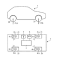
図1は車両1の側面図および平面図を示す。車両1は、それぞれに設けられた車輪荷重センサ4a〜4bを備える車輪2a〜2dと、少なくとも1つの前記車輪2a〜2dの車輪荷重RLa〜RLdを検出するための測定システム3と、横方向の加速度を検出するセンサ5と、横方向の加速度を検出するセンサ6とを含む。さらに図1には、車輪荷重RLa〜RLdの力ベクトルが図示されている。
FIG. 1 shows a side view and a plan view of the vehicle 1. The vehicle 1 includes
図2は測定システム3の詳細図を示す。この測定システムは、無線を介して伝達された車輪荷重RLa〜RLdを検出するための受信器7と、横方向の加速度を検出するための入力側E5と、縦方向の加速度を検出するための入力側E6とを含む。さらに測定システム3は、メモリ8ならびにマイクロコントローラ9を含む。メモリ8はとりわけ、本発明の方法に必要な方程式および方程式パラメータを記憶するために設けられている。通常はこの方法は、メモリ8内のプログラムの形態でファイルされている。マイクロコントローラ9はメモリを読み出し、この方法をステップ毎に処理する。測定システム3はさらに、データベースに送信しかつデータベースから受信するための送受信ユニットを含むことができる(2つとも図示しない)。測定システム3は、車両1の別の制御タスクも実行する搭載コンピュータ(図示しない)の一部分とすることができる。この場合リモートデータベースとの接続は、車両1のGSMインターフェース(Global System for Mobile Communications)またはUMITSインターフェース(Universal Mobile Telecommunications System)を介して構築することができる。しかし以下では簡略化のために、測定システム3が別個の装置であるものとする。
FIG. 2 shows a detailed view of the
図3は車輪2bの拡大図を示す。車輪2bはホイール10とタイヤ11とを含む。タイヤ11の走行面の領域において、タイヤ11の中またはタイヤ11に接してセンサ4bが配置されている。このセンサは車輪接地面Aの長さを測定する。この車輪接地面は、走行路12によって引き起こされる車両荷重RLbに基づくタイヤ11の変形ないしひずみによって生じる。付加的に、タイヤ11の中にはトランスポンダ13が配置されており、このトランスポンダは、例えば識別番号、タイヤタイプ、タイヤ寸法、製造年月日等を保存するために設けられている。さらにこのトランスポンダ13には、方程式および方程式パラメータを保存することも可能である。この実施例の場合、トランスポンダ13は、RFID(Radio Frequency Identification)に関連して設けられた複数の規格のうちの1つに従って動作する。
FIG. 3 shows an enlarged view of the
本発明の方法の機能、ないし測定システム3の機能を、図1〜3に基づいて以下詳細に説明する。要求に基づいて、または繰り返し時点にて、本発明の方法を実施する測定システム3が開始する。簡略化のために、車輪2bの車輪荷重RLbだけが検出されるものとする。もちろん本発明によれば、全ての車輪荷重RLa〜RLdを、シーケンシャルにもパラレルにも検出することが可能である。
The function of the method of the present invention or the function of the
第1ステップa)において、タイヤ11の変形ないしひずみの測定値が検出される。このために例えば、車輪接地面A(Radaufstandsflaeche)の面積または長さが検出される。このことは例えば、タイヤ11に割り当てられたセンサ4b、例えばピエゾセンサによって実施することができる。
In a first step a), a measurement of deformation or strain of the
車輪接地面Aの長さを検出するためのスマートな方法は、この接地面領域を走り抜ける時間を検出することである。このために例えば、加速度センサを使用することができる。この加速度センサにおいては、車輪接地面A内では遠心力の加速度は作用しないが、車輪接地面Aの外では遠心力の加速度が作用する。加速度センサにおいて遠心力の加速度が作用していない間に、車両速度が既知である場合に時間が測定されると、車輪接地面Aの長さを逆算することが可能である。 A smart way to detect the length of the wheel ground plane A is to detect the time to run through this ground plane area. For this purpose, for example, an acceleration sensor can be used. In this acceleration sensor, the acceleration of the centrifugal force does not act inside the wheel contact surface A, but the acceleration of the centrifugal force acts outside the wheel contact surface A. If time is measured when the vehicle speed is known while the acceleration of the centrifugal force is not acting on the acceleration sensor, the length of the wheel contact surface A can be calculated backward.
加速度センサの代わりに、タイヤ11においてピエゾセンサを使用することも可能である。ピエゾセンサは、車輪接地面Aに入る際および車輪接地面Aから出る際に折り曲げられ、車輪接地面Aが進み続ける際には直線状に形成されている。このような変形パターンからも車輪接地面が進み続けるために必要な時間スパンを推量することができるので、車輪接地面Aの長さを検出することが可能である。
It is also possible to use a piezo sensor in the
もちろん車輪接地面Aの長さを測定する以外にも、別のパラメータ、例えば側壁の変形またはタイヤ11の走行面とホイール10との間の間隔などを測定することも可能である。
Of course, in addition to measuring the length of the wheel ground contact surface A, other parameters such as deformation of the side wall or the distance between the running surface of the
第2ステップb)において、測定された変形から車輪加重RLbが計算される。タイヤ11の変形は、すなわちこのタイヤに作用する車輪荷重RLbに依存している。車輪荷重RLbが増大するにつれて車輪接地面積Aおよび車輪接地長さも増大する。基本的に、車輪接地面Aの長さから車輪荷重RLbを逆算することが可能である。
In a second step b), the wheel weight RLb is calculated from the measured deformation. The deformation of the
車輪荷重RLb以外にも多数の別の影響要素が存在する。例えばタイヤ圧力やタイヤ温度といった比較的簡単に測定できる要素もあれば、測定できない要素や高い技術的コストによってしか測定できない要素もある。例えばゴムコンパウンドの弾性は、温度に依存している。確かに、温度それ自体は簡単に測定することができる。しかしながら例えばタイヤ11の側面が太陽によって照射された場合には、タイヤ11内で大きな温度差が生じ得る。また弾性は、例えばタイヤ11の年数や、タイヤがいかなる条件のもとで劣化したのかという劣化条件にも依存している。
There are many other influencing factors other than the wheel load RLb. For example, some elements can be measured relatively easily, such as tire pressure and tire temperature, while others cannot be measured or can only be measured at high technical costs. For example, the elasticity of rubber compounds depends on temperature. Certainly, the temperature itself can be easily measured. However, for example, when the side surface of the
このような不確定な要因のために第3ステップc)において、車輪荷重RLbか、もしくは車輪荷重RLbを算出する際に用いられる車輪荷重に依存した変数が、外部のシステムから取得される。このために、示した実施例においては、横方向の加速度センサ5からの値と縦方向の加速度センサ6からの値とが読み出される。車両1の重量および重心が既知である場合には、測定システム3は、車輪2a〜2dに作用する車輪荷重RLa〜RLdを計算することが可能である。択一的に、これらの値をテーブルに記憶することもできる。別の実施例では、測定システム3には、縦方向の加速度および横方向の加速度が伝達されるのではなく、直接、車輪荷重RLa〜RLdが伝達される。これを例えば既存の搭載コンピュータにおいて計算し、その後測定システム3に伝達することができる。もちろん、測定システム3が完全に搭載コンピュータの構成部材であること、つまり搭載コンピュータに組み込まれていることも考えられる。測定システム3を、搭載コンピュータのハードウェアおよび/またはソフトウェアの一部とすることもできる。
Due to such uncertain factors, in the third step c), the wheel load RLb or a variable depending on the wheel load used in calculating the wheel load RLb is obtained from an external system. For this purpose, in the illustrated embodiment, the value from the
択一的にまたは付加的に、前記車輪負荷RLa〜RLdに依存した変数としてアクティブダンパーシステムの制御変数も測定することができ、この制御変数から車輪荷重RLa〜RLdを検出することが可能である。とりわけ最新の高級クラスの車両の場合には、いずれにせよこのようなデータを使用することが可能である。本発明の別の実施例においては、パッシブダンパーシステムのサスペンションコンプレックス(Einfederweg)が測定される。スプリングストラットのばね定数が既知である場合、このサスペンションコンプレックスから車輪荷重RLa〜RLdを計算することが可能である。同一の軸に取り付けられた車輪2aの車輪荷重RLaを、別の方法ステップのために使用することも考えられる。とりわけ横方向の加速度が無い場合には、車輪荷重RLa、RLdが1つの軸に等分されていると仮定することができる。最後に、全体重量および重心位置が、少なくとも車両が静止状態にある場合には、車両荷重を検出するための比較的簡単な手段を提供する。しかし、車両速度、および風力によって引き起こされかつ車両1に作用するモーメント、および/または操舵角、および操舵角と結びついた横方向の加速度もまた、車輪荷重RLa〜RLdを計算するために使用することができる。
Alternatively or additionally, control variables of the active damper system can also be measured as variables dependent on the wheel loads RLa to RLd, and the wheel loads RLa to RLd can be detected from these control variables. . In particular, in the case of the latest luxury class vehicle, it is possible to use such data anyway. In another embodiment of the invention, the suspension complex (Einfederweg) of the passive damper system is measured. If the spring constant of the spring strut is known, the wheel loads RLa to RLd can be calculated from this suspension complex. It is also conceivable to use the wheel load RLa of the
第4ステップd)において、ステップb)にて算出された、すなわちタイヤの変形によって算出された車輪加重RLbと、ステップc)にて算出された、すなわち車輪荷重RLbに依存した別の変数によって検出された車輪荷重RLbとが比較される。最も簡単な実施例においては、これら2つの値の差または商を算出することができる。しかし別のより複雑な比較も考えられる。 In the fourth step d), detected by the wheel weight RLb calculated in step b), that is, calculated by tire deformation, and another variable calculated in step c), that is, dependent on the wheel load RLb. The wheel load RLb thus made is compared. In the simplest embodiment, the difference or quotient of these two values can be calculated. But other more complex comparisons are possible.
第5ステップe)において、方程式および/または方程式パラメータが、ステップd)の結果に基づいて適合される。これに関して方程式パラメータは以下のように修正される。すなわち、タイヤの変形によって検出された車輪荷重RLbと、外部システムから取得された車輪荷重RLbとの間の差が縮まるように修正されるのである。 In a fifth step e), equations and / or equation parameters are adapted based on the result of step d). In this regard, the equation parameters are modified as follows: That is, correction is made so that the difference between the wheel load RLb detected by the deformation of the tire and the wheel load RLb acquired from the external system is reduced.
もちろん、車輪荷重RLa〜RLdの間のずれに関するより精確な状況像を得るために、本発明の方法は種々異なる動作条件下において繰り返し実行することができる。方程式のパラメータの適合が充分でない場合には、とりわけより良好な現実のモデルを形成する別の方程式セットと交換することができる。実際に、現実を数学的に把握するための種々異なる数式がしばしば存在する。この際に本発明は、最良のモデルを探し出すのに役立つ。 Of course, in order to obtain a more accurate picture of the situation regarding the deviation between the wheel loads RLa to RLd, the method according to the invention can be carried out repeatedly under different operating conditions. If the equation parameters are not well matched, they can be exchanged with another set of equations that form a better real model, among other things. In fact, there are often different mathematical formulas for mathematically grasping the reality. In this case, the present invention helps to find the best model.
方程式および/または方程式パラメータの適合は、この適合が有利なスタート時点において開始する場合に特に迅速に実施することができる。したがって方程式および/または方程式パラメータ、ないしはこれらの検出を可能にするデータは、タイヤ11に設けられたトランスポンダ13(例えばRFIDトランスポンダ)か、リモートデータベースか、もしくは、同一の車両1に取り付けられた同じタイプの別のタイヤ11から読み出すことができる。最後のケースにおいては、同一車軸のタイヤ11によるデータが使用されると有利である。
The adaptation of equations and / or equation parameters can be carried out particularly quickly when this adaptation starts at an advantageous starting point. The equations and / or equation parameters or the data enabling these detections can therefore be obtained from a transponder 13 (for example an RFID transponder) provided on the
有利には、方程式および/または方程式パラメータ、ないしはこれらの検出を可能にするデータを再保存することも考えられる。一つの例は、夏用/冬用タイヤの取りはずしであり、この夏用/冬用タイヤは、半年後に再び同一の車両1に取り付けられる。 Advantageously, it is also conceivable to re-save the equations and / or equation parameters or the data enabling their detection. One example is the removal of a summer / winter tire, which is mounted on the same vehicle 1 again after six months.
Claims (16)
a)タイヤ(11)の変形の測定値を検出し、
b)タイヤ(11)に作用する車輪荷重(RLb)を、測定された前記変形と、方程式および方程式パラメータのセットと、を用いて算出し、
c)外部のシステムから、車輪荷重(RLb)を取得するか、もしくは車輪荷重に依存した変数を取得して、該変数を用いて車輪荷重(RLb)を算出し、
d)ステップb)において算出された車輪荷重(RLb)と、ステップc)において取得された車輪荷重(RLb)と、を比較し、
e)前記比較に基づいて、前記方程式および/または方程式パラメータを適合させる、
ことを特徴とする方法。 In a method for detecting wheel load (RLb),
a) detecting the measurement of deformation of the tire (11) ,
The b) the wheel load acting on the tire (11) (RLb), calculated using the measured the deformation, the set of equations and equation parameters, and
c) Obtaining wheel load (RLb) from an external system or obtaining a variable depending on the wheel load and calculating the wheel load (RLb) using the variable,
compared to d) wheel load calculated in step b) (RLb), and the obtained wheel load (RLb) in step c), the,
e) adapting the equation and / or equation parameters based on the comparison;
A method characterized by that.
アクティブダンパーシステムの制御変数、パッシブダンパーシステムのサスペンションコンプレックス(Einfederweg)、縦方向の加速度、横方向の加速度、同一の軸に取り付けられた車輪(2a)の車輪荷重(RLa)、車両全体重量、重心位置、ブレーキデータ、車両速度および/または操舵角、
を含むグループから1つまたは複数の変数を採用する、
請求項1記載の方法。 As a variable depending on the wheel load (RLb),
Control variable of active damper system, suspension complex of passive damper system (Einfederweg), longitudinal acceleration, lateral acceleration, wheel load (RL a ) of wheels (2a) mounted on the same axis, overall vehicle weight, Center of gravity, brake data, vehicle speed and / or steering angle,
Employ one or more variables from the group comprising,
請 Motomeko 1 method described.
または、
最初のステップにおいて、タイヤ(11)の中ないしタイヤ表面上に取り付けられているトランスポンダ(13)に保存されたデータが読み出され、この読み出されたデータに基づいて方程式および/または方程式パラメータが検出される、
請求項1または2記載の方法。 In The first step, or equations and / or equation parameters or stored in the transponder (13) mounted on the tire surface in a tire (11) is read,
Or
In The first step, the tire data stored to the transponder (13) mounted on the tire surface in the (11) is read, equations and / or equation parameters based on the read data Is detected ,
請 Motomeko 1 or 2 A method according.
または、
最初のステップにおいて、リモートデータベースに保存された、タイヤ(11)またはタイヤタイプに割り当てられているデータが読み出され、この読み出されたデータに基づいて方程式および/または方程式パラメータが検出される、
請求項1または2記載の方法。 In The first step, or stored in a remote database, equations and / or equation parameters are assigned to the tire (11) or tire type is read,
Or
In The first step was stored on a remote database, data is read out which is assigned to the tire (11) or tire type, equations and / or equation parameters are detected on the basis of the read data ,
請 Motomeko 1 or 2 A method according.
請求項1〜4のいずれか一項記載の方法。 The equations and / or equation parameters are communicated to the remote database ;
The method of any one claim of 請 Motomeko 1-4.
請求項1または2のいずれか一項記載の方法。 Said equation and / or equation parameters are derived in a first step from another tire of the same type attached to the same vehicle (1) ,
請 Motomeko 1 or method of any one claim of 2.
かつ、
方程式および/または方程式パラメータを、タイヤ(11)、またはタイヤ(11)の取り付けられている車輪(2b)を取りつけた後に、最初のステップにおいて再び読み出す、
請求項1〜6のいずれか一項記載の方法。 How formula and / or equation parameters extent, and stored prior to removal of the wheel (2b) mounted a tire (11), or tire (11),
And,
How the equations and / or equation parameters, after mounting the tire (11), or tire (11) mounted to have a wheel with (2b), read again in the first step,
The method of any one claim of 請 Motomeko 1-6.
a)タイヤ(11)の変形の測定値を検出する手段と、
b)タイヤ(11)に作用する車輪荷重(RLb)を、測定された前記変形と、方程式および方程式パラメータのセットと、を用いて算出する手段と、
c)外部のシステムから、車輪荷重(RLb)を取得するか、もしくは車輪荷重(RLb)を算出する際に用いられる車輪荷重に依存した変数を取得する手段と、
d)前記b)に記載の手段によって算出された車輪荷重(RLb)と、前記c)に記載の手段によって取得された車輪荷重(RLb)と、を比較する手段と、
e)前記比較に基づいて、前記方程式および/または方程式パラメータを適合させる手段と、
を含むことを特徴とする測定システム(3)。 In the measurement system (3) for detecting the wheel load (RLb),
It means for detecting a measure of the deformation of a) the tire (11),
The b) the wheel load acting on the tire (11) (RLb), and measured the deformation, and means for calculating using a set of equations and equation parameters, and
c) From the outside of the system, means for obtaining a variable that depends on the wheel load is used to calculate how to obtain the wheel load (RLb), or wheel load the (RLb),
and d) said b) wheel load calculated by the means described in (RLb), means for comparing, with the wheel load (RLb) obtained by the means described in the c),
means e) based on said comparison, adapting the equations and / or equation parameters,
A measurement system (3) characterized by comprising:
前記検出手段は、前記半導体構成素子の少なくとも1つの入力側を形成する、
請求項8記載の測定システム(3)。 The means for calculating the wheel load (RLb) acting on the tire (11), the comparing means, and the adapting means are arranged in one semiconductor component;
The detection means forms at least one input side of the semiconductor component ;
請 Motomeko 8, wherein the measuring system (3).
請求項8または9記載の測定システム(3)。 The measurement system includes at least one sensor (4b) for measuring deformation of the tire (11) .
請 Motomeko 8 or 9, wherein the measuring system (3).
前記車輪荷重に依存した変数として、
アクティブダンパーシステムの制御変数、パッシブダンパーシステムのサスペンションコンプレックス(Einfederweg)、縦方向の加速度、横方向の加速度、同一の軸に取り付けられた車輪(2a)の車輪荷重(RLa)、車両全体重量、重心位置、ブレーキデータ、車両速度および/または操舵角
を含むグループから1つまたは複数の変数が採用されている、
請求項8〜10のいずれか一項記載の測定システム(3)。 The measurement system (3) comprises a wheel load (RLa~RLd) or wheel load (RLa~RLd) dependent variables input for acquiring external system or al a a (EA to ED),
As a variable depending on the wheel load,
Control variable of active damper system, suspension complex of passive damper system (Einfederweg), longitudinal acceleration, lateral acceleration, wheel load (RL a ) of wheels (2a) mounted on the same axis, overall vehicle weight, One or more variables are employed from the group including center of gravity position, brake data, vehicle speed and / or steering angle ,
Measurement system according to one of 請 Motomeko 8-10 (3).
または、
前記測定システム(3)は、トランスポンダ(13)に保存された、方程式および/または方程式パラメータを検出するために適当なデータを読み出すための読み出し装置を含む、
請求項8〜11のいずれか一項記載の測定システム(3)。 Before or SL measuring system (3) comprises a reading device for reading the equations and / or equation parameters stored in the transponder (13) mounted on the inside of the tire (11) to the tire surface,
Or
Before SL measuring system (3) comprises a reading device for reading the appropriate data to detect stored in the transponder (13), equations and / or equation parameters,
Measurement system according to one of 請 Motomeko 8-11 (3).
または、
前記測定システム(3)は、リモートデータベースに保存された、タイヤ(11)またはタイヤタイプに割り当てられている、方程式および/または方程式パラメータを検出するために適当なデータを受信する受信器を含む、
請求項8〜11のいずれか一項記載の測定システム(3)。 Before SL measuring system (3) it is stored in a remote database, or comprises a receiver for receiving equations and / or equation parameters are assigned to the tire (11) or tire type,
Or
Before SL measuring system (3) includes stored in a remote database is assigned to the tire (11) or tire type, a receiver for receiving an appropriate data to detect equations and / or equation parameter ,
Measurement system according to one of 請 Motomeko 8-11 (3).
請求項8〜13のいずれか一項記載の測定システム(3)。 The measurement system (3) includes a transmitter for transmitting equations and / or equation parameters to a remote database ;
Measurement system according to one of 請 Motomeko 8-13 (3).
または
前記測定システム(3)は、同じ車両(1)に取りつけられた同じタイプの別のタイヤに割り当てられた、方程式および/または方程式パラメータを検出するために適当なデータを検出する手段を含む、
請求項8〜14のいずれか一項記載の測定システム(3)。 Before or SL measuring system (3) includes means for detecting the equations and / or equation parameter by another tire of the same type mounted on the same vehicle (1),
Or
Before SL measuring system (3) is assigned to a different tire of the same type mounted on the same vehicle (1) includes means for detecting an appropriate data to detect equations and / or equation parameters,
Measurement system according to one of 請 Motomeko 8-14 (3).
かつ、
前記測定システム(3)は、方程式および/または方程式パラメータを、タイヤ(11)、またはタイヤ(11)の取り付けられている車輪(2a)を取りつけた後に読み出す手段を含む、
請求項8〜15のいずれか一項記載の測定システム(3)。 Before SL measuring system (3) includes means for storing the equations and / or equation parameters, before removing the tire (11), or tire (11) mounted to have a wheel with (2b),
And,
Before SL measuring system (3) includes means for reading the equations and / or equation parameters, after mounting the tire (11), or tire wheels mounted with (11) (2 a),
Measurement system according to one of 請 Motomeko 8-15 (3).
Applications Claiming Priority (2)
| Application Number | Priority Date | Filing Date | Title |
|---|---|---|---|
| DE102008046269A DE102008046269B3 (en) | 2008-09-08 | 2008-09-08 | Wheel load determining method for passenger car, involves comparing calculated wheel load with detected wheel load, and performing adaptation of equations and/or equation parameters based on comparison |
| DE102008046269.1 | 2008-09-08 |
Publications (3)
| Publication Number | Publication Date |
|---|---|
| JP2010066261A JP2010066261A (en) | 2010-03-25 |
| JP2010066261A5 JP2010066261A5 (en) | 2012-10-18 |
| JP5502404B2 true JP5502404B2 (en) | 2014-05-28 |
Family
ID=41335217
Family Applications (1)
| Application Number | Title | Priority Date | Filing Date |
|---|---|---|---|
| JP2009206608A Active JP5502404B2 (en) | 2008-09-08 | 2009-09-08 | Method and measuring system for detecting wheel load |
Country Status (3)
| Country | Link |
|---|---|
| US (1) | US8255114B2 (en) |
| JP (1) | JP5502404B2 (en) |
| DE (1) | DE102008046269B3 (en) |
Cited By (1)
| Publication number | Priority date | Publication date | Assignee | Title |
|---|---|---|---|---|
| WO2016009601A1 (en) * | 2014-07-16 | 2016-01-21 | 株式会社デンソー | Tire state detection device |
Families Citing this family (29)
| Publication number | Priority date | Publication date | Assignee | Title |
|---|---|---|---|---|
| FR2962689B1 (en) * | 2010-07-13 | 2014-01-31 | Michelin Soc Tech | METHOD FOR ESTIMATING THE DYNAMIC LOAD CARRIED OUT BY A TIRE OF A VEHICLE |
| CN103148830B (en) * | 2013-02-25 | 2015-11-04 | 桂林理工大学 | Based on the structural deformation pick-up unit of Internet of Things |
| CN103148829B (en) * | 2013-02-25 | 2015-11-04 | 桂林理工大学 | Based on the structural deformation detection method of Internet of Things |
| US9222854B2 (en) * | 2013-03-12 | 2015-12-29 | The Goodyear Tire & Rubber Company | Vehicle dynamic load estimation system and method |
| US10150456B2 (en) * | 2013-06-28 | 2018-12-11 | Continental Automotive Systems, Inc. | Apparatus and method to dynamically adjust electronic braking using TPMS |
| US20150375576A1 (en) * | 2014-06-26 | 2015-12-31 | Caterpillar Inc. | Tire Based Method and Device for Measuring Running Surface Strength |
| US9739689B2 (en) | 2014-11-21 | 2017-08-22 | The Goodyear Tire & Rubber Company | Tire cornering stiffness estimation system and method |
| US9963146B2 (en) | 2014-12-03 | 2018-05-08 | The Goodyear Tire & Rubber Company | Tire lift-off propensity predictive system and method |
| US9340211B1 (en) | 2014-12-03 | 2016-05-17 | The Goodyear Tire & Rubber Company | Intelligent tire-based road friction estimation system and method |
| US9650053B2 (en) | 2014-12-03 | 2017-05-16 | The Goodyear Tire & Rubber Company | Slip ratio point optimization system and method for vehicle control |
| GB2533658A (en) * | 2014-12-22 | 2016-06-29 | Continental Automotive Gmbh | Method and system for determining a wheel load acting on a tire of a vehicle |
| US9573591B2 (en) * | 2015-03-18 | 2017-02-21 | Continental Automotive Systems, Inc. | System and method utilizing detected load for vehicle handling |
| CN104806363B (en) * | 2015-03-31 | 2018-07-27 | 小米科技有限责任公司 | Throttle response method and device |
| DE102015217916B4 (en) * | 2015-09-18 | 2017-06-08 | Schaeffler Technologies AG & Co. KG | Motor vehicle and method for determining a wheel contact force for each wheel of a motor vehicle |
| JP6488986B2 (en) | 2015-10-27 | 2019-03-27 | 株式会社Soken | Road surface condition estimation device |
| DE102015223970B4 (en) | 2015-12-02 | 2020-01-16 | Continental Automotive Gmbh | Method and device for determining a wheel load on a vehicle wheel |
| GB201615674D0 (en) * | 2016-09-15 | 2016-11-02 | Continental Automotive Gmbh | Method and device for determining a wheel load acting on a wheel of a vehicle, and method and device for determining a weight of a vehicle |
| DE102017207620B4 (en) * | 2017-05-05 | 2019-05-29 | Continental Automotive Gmbh | Method and device for determining wheel loads on wheels of a vehicle |
| CN108225659B (en) * | 2017-12-27 | 2020-03-24 | 深圳市道通科技股份有限公司 | Tire pressure sensor information acquisition method and device, storage medium and electronic equipment |
| US10875539B2 (en) | 2018-08-22 | 2020-12-29 | Infineon Technologies Ag | Tire load estimation |
| US11298991B2 (en) | 2018-11-28 | 2022-04-12 | The Goodyear Tire & Rubber Company | Tire load estimation system and method |
| CN113242963A (en) | 2018-12-14 | 2021-08-10 | 基斯特勒控股公司 | Calibration of WIM sensors |
| JP2020131911A (en) * | 2019-02-19 | 2020-08-31 | 株式会社Soken | Tire air pressure monitoring system |
| US11774301B2 (en) | 2020-06-16 | 2023-10-03 | The Goodyear Tire & Rubber Company | Tire load estimation system and method |
| CN112093731B (en) * | 2020-08-24 | 2022-10-11 | 山东华伟重特机械有限公司 | Reinforced forklift goods blocking rack |
| JP7407098B2 (en) * | 2020-11-11 | 2023-12-28 | 株式会社ブリヂストン | Tire load prediction system, tire load prediction program, and tire load prediction method |
| JP2022119119A (en) * | 2021-02-03 | 2022-08-16 | 株式会社ブリヂストン | Apparatus and method for controlling vehicle |
| CN113532609A (en) * | 2021-07-14 | 2021-10-22 | 广东电子工业研究院有限公司 | Vehicle-mounted load detection system and calibration method |
| DE102022118311A1 (en) | 2022-07-21 | 2024-02-01 | Audi Aktiengesellschaft | Motor vehicle with a steering means and method for providing a feedback torque for the steering means |
Family Cites Families (14)
| Publication number | Priority date | Publication date | Assignee | Title |
|---|---|---|---|---|
| DE4435160A1 (en) * | 1994-09-30 | 1996-04-04 | Continental Ag | Device for determining the peripheral force of a vehicle wheel |
| FR2809488A1 (en) * | 2000-05-26 | 2001-11-30 | Michelin & Cie | METHOD FOR DETERMINING COMPONENTS OF EFFORTS SUBJECTED BY A TIRE |
| US6550320B1 (en) * | 2000-05-31 | 2003-04-22 | Continental Ag | System and method for predicting tire forces using tire deformation sensors |
| DE10146031A1 (en) * | 2001-09-18 | 2003-04-24 | Continental Ag | Procedure for determining tire pressure and wheel load of vehicle tires |
| US6539295B1 (en) * | 2002-01-18 | 2003-03-25 | Ford Global Technologies, Inc. | Vehicle tire monitoring system with multiple sensors |
| US7536903B2 (en) * | 2003-12-11 | 2009-05-26 | Conti Temic Microelectronic Gmbh | Sensor transponder and procedure for measuring tire contact lengths and wheel load |
| JP4680532B2 (en) * | 2004-06-02 | 2011-05-11 | 株式会社ブリヂストン | Method and apparatus for estimating dynamic state of tire |
| DE102005048794A1 (en) * | 2004-08-03 | 2007-04-19 | Rainer Wychnanek | Vehicle e.g. lorry, wheel`s load measuring device, has stress sensors, rim, tires, electrical source, evaluation electronic circuit and transmitter, which are fixedly connected with each other, where sensors are arranged in hub area of rim |
| JP4713863B2 (en) * | 2004-08-27 | 2011-06-29 | 住友電気工業株式会社 | TIRE SENSOR UNIT, TIRE STATE DETECTION DEVICE, AND TIRE |
| WO2006038585A1 (en) * | 2004-10-05 | 2006-04-13 | The Yokohama Rubber Co., Ltd. | Pneumatic tire and method for mounting transponder on pneumatic tire |
| JP2007147520A (en) * | 2005-11-29 | 2007-06-14 | Toyota Motor Corp | Wheel condition estimation device, and vehicle controller |
| DE102006033951A1 (en) * | 2006-07-22 | 2007-10-25 | Audi Ag | Device for determining wheel load of tire of motor vehicle has pressure sensor by which at least tire inflation pressure can be determined regardless of tire rotation speed |
| EP1978345B1 (en) * | 2007-04-06 | 2014-05-07 | Sumitomo Rubber Industries, Ltd. | Method for estimating magnitude of force acting on rolling tire |
| US7472587B1 (en) * | 2007-09-18 | 2009-01-06 | Infineon Technologies Ag | Tire deformation detection |
-
2008
- 2008-09-08 DE DE102008046269A patent/DE102008046269B3/en active Active
-
2009
- 2009-09-08 US US12/555,427 patent/US8255114B2/en not_active Expired - Fee Related
- 2009-09-08 JP JP2009206608A patent/JP5502404B2/en active Active
Cited By (2)
| Publication number | Priority date | Publication date | Assignee | Title |
|---|---|---|---|---|
| WO2016009601A1 (en) * | 2014-07-16 | 2016-01-21 | 株式会社デンソー | Tire state detection device |
| JP2016022761A (en) * | 2014-07-16 | 2016-02-08 | 株式会社日本自動車部品総合研究所 | Tire state detection device |
Also Published As
| Publication number | Publication date |
|---|---|
| US20100063671A1 (en) | 2010-03-11 |
| DE102008046269B3 (en) | 2009-12-24 |
| US8255114B2 (en) | 2012-08-28 |
| JP2010066261A (en) | 2010-03-25 |
Similar Documents
| Publication | Publication Date | Title |
|---|---|---|
| JP5502404B2 (en) | Method and measuring system for detecting wheel load | |
| JP2010066261A5 (en) | ||
| US11298991B2 (en) | Tire load estimation system and method | |
| US10399396B2 (en) | System and method for determining at least one tire contact area parameter characterizing a dimension of a tire contact area on a tire of a wheel of a vehicle | |
| CN112440628B (en) | Tire wear estimation system and method using footprint length | |
| CN111247010B (en) | Determining tire change status in a vehicle | |
| JP5559204B2 (en) | Method and apparatus for continuously detecting wheel state quantities of wheels | |
| US20130179113A1 (en) | Method of sampling acceleration measurements of a motor vehicle wheel | |
| US10352758B2 (en) | Apparatus for estimating vehicle mass using tire air pressure and method thereof | |
| CN111433054B (en) | Method and system for monitoring parameters related to a tyre during the running of a vehicle | |
| JP2005528270A (en) | Vehicle tire and vehicle monitoring method, vehicle / tire correlation model generation method, vehicle diagnostic system | |
| CN111511588A (en) | Determining tire pressure status in a vehicle | |
| US8798850B2 (en) | Method and measurement system for localizing at least one wheel on a motor vehicle | |
| CN115158335A (en) | Enhanced method and system for estimating working efficiency and endurance mileage of electric vehicle tire | |
| US20210061020A1 (en) | Tire wear state estimation system and method employing footprint shape factor | |
| US20080276700A1 (en) | Method for monitoring the tire condition in vehicles | |
| JP2007526847A (en) | How to identify the type of tire attached to a vehicle | |
| US20240351381A1 (en) | Method and system for monitoring a parameter related to a tire during the running of a vehicle | |
| CN113710505A (en) | System for determining the state of a vehicle tyre | |
| CN115923409A (en) | Load estimation system for a tire | |
| CN115782473A (en) | System for estimating reverse deflection load of tire | |
| TR201617062A2 (en) | TIRE PRESSURE MEASUREMENT SYSTEM |
Legal Events
| Date | Code | Title | Description |
|---|---|---|---|
| RD04 | Notification of resignation of power of attorney |
Free format text: JAPANESE INTERMEDIATE CODE: A7424 Effective date: 20101228 |
|
| A521 | Request for written amendment filed |
Free format text: JAPANESE INTERMEDIATE CODE: A523 Effective date: 20120904 |
|
| A621 | Written request for application examination |
Free format text: JAPANESE INTERMEDIATE CODE: A621 Effective date: 20120904 |
|
| A977 | Report on retrieval |
Free format text: JAPANESE INTERMEDIATE CODE: A971007 Effective date: 20131031 |
|
| A131 | Notification of reasons for refusal |
Free format text: JAPANESE INTERMEDIATE CODE: A131 Effective date: 20131105 |
|
| A521 | Request for written amendment filed |
Free format text: JAPANESE INTERMEDIATE CODE: A523 Effective date: 20140120 |
|
| TRDD | Decision of grant or rejection written | ||
| A01 | Written decision to grant a patent or to grant a registration (utility model) |
Free format text: JAPANESE INTERMEDIATE CODE: A01 Effective date: 20140212 |
|
| A61 | First payment of annual fees (during grant procedure) |
Free format text: JAPANESE INTERMEDIATE CODE: A61 Effective date: 20140313 |
|
| R150 | Certificate of patent or registration of utility model |
Ref document number: 5502404 Country of ref document: JP Free format text: JAPANESE INTERMEDIATE CODE: R150 |
|
| R250 | Receipt of annual fees |
Free format text: JAPANESE INTERMEDIATE CODE: R250 |
|
| R250 | Receipt of annual fees |
Free format text: JAPANESE INTERMEDIATE CODE: R250 |
|
| R250 | Receipt of annual fees |
Free format text: JAPANESE INTERMEDIATE CODE: R250 |
|
| R250 | Receipt of annual fees |
Free format text: JAPANESE INTERMEDIATE CODE: R250 |
|
| R250 | Receipt of annual fees |
Free format text: JAPANESE INTERMEDIATE CODE: R250 |
|
| R250 | Receipt of annual fees |
Free format text: JAPANESE INTERMEDIATE CODE: R250 |
|
| R250 | Receipt of annual fees |
Free format text: JAPANESE INTERMEDIATE CODE: R250 |
|
| S111 | Request for change of ownership or part of ownership |
Free format text: JAPANESE INTERMEDIATE CODE: R313113 |
|
| S631 | Written request for registration of reclamation of domicile |
Free format text: JAPANESE INTERMEDIATE CODE: R313631 |
|
| R350 | Written notification of registration of transfer |
Free format text: JAPANESE INTERMEDIATE CODE: R350 |