JP5501041B2 - Image processing apparatus, image processing method, and program - Google Patents
Image processing apparatus, image processing method, and program Download PDFInfo
- Publication number
- JP5501041B2 JP5501041B2 JP2010058299A JP2010058299A JP5501041B2 JP 5501041 B2 JP5501041 B2 JP 5501041B2 JP 2010058299 A JP2010058299 A JP 2010058299A JP 2010058299 A JP2010058299 A JP 2010058299A JP 5501041 B2 JP5501041 B2 JP 5501041B2
- Authority
- JP
- Japan
- Prior art keywords
- color
- image data
- information
- rotation
- image processing
- Prior art date
- Legal status (The legal status is an assumption and is not a legal conclusion. Google has not performed a legal analysis and makes no representation as to the accuracy of the status listed.)
- Expired - Fee Related
Links
Images


Classifications
-
- H—ELECTRICITY
- H04—ELECTRIC COMMUNICATION TECHNIQUE
- H04N—PICTORIAL COMMUNICATION, e.g. TELEVISION
- H04N1/00—Scanning, transmission or reproduction of documents or the like, e.g. facsimile transmission; Details thereof
- H04N1/387—Composing, repositioning or otherwise geometrically modifying originals
- H04N1/3877—Image rotation
-
- H—ELECTRICITY
- H04—ELECTRIC COMMUNICATION TECHNIQUE
- H04N—PICTORIAL COMMUNICATION, e.g. TELEVISION
- H04N1/00—Scanning, transmission or reproduction of documents or the like, e.g. facsimile transmission; Details thereof
- H04N1/46—Colour picture communication systems
- H04N1/64—Systems for the transmission or the storage of the colour picture signal; Details therefor, e.g. coding or decoding means therefor
Description
本発明は、画像を所定のブロック単位に圧縮する画像データ圧縮処理、当該ブロック単位に圧縮されたデータへの画像処理、および画像データへ復元処理を行う画像処理装置、画像処理方法、及びプログラムに関する。特に、圧縮されたデータの復元時の回転処理に関する。 The present invention relates to an image data compression process for compressing an image in a predetermined block unit, an image process for data compressed in the block unit, and an image processing apparatus, an image processing method, and a program for performing a restoration process on image data . In particular, the present invention relates to a rotation process when decompressing compressed data.
従来、高解像度のカラー画像への需要は高く、それらの高画質化への要望へ応えるべくデジタル複合機では、1200dpi(dots per inch)やそれを超える解像度の画像を扱う事が多くなってきている。デジタル複合機に限らずこれら画像を扱う画像処理装置(デジタルカメラやファクシミリ装置)では、メモリ/ハードディスク量の節約や、それらへの書き込み時間を短縮するために、カラー画像データの圧縮を行い、低コスト化や高速化を実現している。従来、カラー静止画像の圧縮方式には、離散コサイン変換を利用したJPEG方式や、Wabelet変換を利用した方式が多く使われている。 Conventionally, demand for high-resolution color images has been high, and in order to meet these demands for higher image quality, digital multifunction devices are increasingly handling images with resolutions of 1200 dpi (dots per inch) and beyond. Yes. Image processing apparatuses (digital cameras and facsimile machines) that handle these images, not limited to digital multi-function peripherals, compress color image data to save memory / hard disk capacity and reduce writing time. Cost and speed have been realized. Conventionally, as a compression method for color still images, a JPEG method using discrete cosine transform and a method using Wavelet transform are often used.
高解像度化が進むにつれて回転処理に代表される画像処理を必要とする画素数が飛躍的に増えその処理負荷が増大しているという課題もある。例えば600dpiから1200dpiに解像度が倍になることで処理すべき画素数は4倍になる。前述した画像圧縮を用いた場合はその画素データを参照し、その画素データを変換しようとすると圧縮データの復号処理が必要になってくる。つまり圧縮データのままで回転処理に代表される画像処理を行う事は出来ず、必ず復号処理が必要になり、高解像度データ全ての画素に対して画素単位に処理を行う必要が出てしまい、処理時間の増大をまねくこととなる。 There is also a problem that as the resolution increases, the number of pixels that require image processing represented by rotation processing increases dramatically, and the processing load increases. For example, when the resolution is doubled from 600 dpi to 1200 dpi, the number of pixels to be processed is quadrupled. When the above-described image compression is used, the pixel data is referred to, and if the pixel data is to be converted, a decoding process of the compressed data becomes necessary. In other words, image processing represented by rotation processing cannot be performed with compressed data as it is, decoding processing is always necessary, and it is necessary to perform processing on a pixel basis for all pixels of high resolution data, This will increase the processing time.
符号化された画像を復号時に回転させる画像符号化装置として、特許文献1がある。特許文献1に記載の画像符号化装置によれば、画像をM×N画素のブロックに分割・可変長符号化し、画像のブロック単位の可変長符号ごとに符号長を示す符号情報と格納される先頭アドレスを付加する。復号時に90°、180°、270°の回転をさせる場合ブロックの読み出し順序を変えている。
As an image encoding device that rotates an encoded image at the time of decoding, there is
しかしながら、特許文献1に記載の画像符号化装置では、復号してバッファに格納しバンドメモリに転送する際に各ブロック内の画像を回転させるので、高速演算器又は専用ハードウェアが必要なうえバッファ用のメモリが必要になり、高価になってしまう。さらに、圧縮されたデータを復号した後、回転を行うため、高解像度画像の処理には時間が掛かってしまう。
However, in the image encoding device described in
本発明は、このような問題を鑑みてなされたもので、その目的とするところは、圧縮データの状態で回転処理を容易に行うことで、安価でかつ高解像度画像でも処理時間が短い画像処理装置を提供することにある。 The present invention has been made in view of such problems, and an object of the present invention is to perform image processing that is inexpensive and has a short processing time even for high-resolution images by easily performing rotation processing in the state of compressed data. To provide an apparatus.
上記課題を解決するために、本発明は以下の構成を有する。入力された画像データを圧縮された状態で回転可能とする画像処理装置であって、前記画像データの回転角度を記憶する記憶手段と、前記画像データにおいて、所定の数の画素からなるブロックにより構成されるタイルごとに、圧縮することによって得られた前記ブロックにおける色の配置の情報と、前記色の配置に対応する色情報と、前記画像データにおける当該タイルの位置の情報とを保持する保持手段と、前記記憶手段にて記憶した当該画像データの回転角度に応じて前記ブロックにおける色の配置を変換し、変換された色の配置、配置に対応する色情報、及び前記タイルの位置の情報から回転後の画像データを形成する回転手段とを有する。 In order to solve the above problems, the present invention has the following configuration. An image processing apparatus capable of rotating input image data in a compressed state, comprising storage means for storing a rotation angle of the image data, and a block comprising a predetermined number of pixels in the image data Holding means for holding color arrangement information in the block obtained by compression, color information corresponding to the color arrangement, and position information of the tile in the image data for each tile to be compressed And the color arrangement in the block according to the rotation angle of the image data stored in the storage means, and the converted color arrangement, the color information corresponding to the arrangement, and the tile position information Rotation means for forming image data after rotation.
本発明によれば、安価でかつ高解像度画像でも処理時間が短い回転画像処理を実現することができる。 According to the present invention, it is possible to realize rotated image processing that is inexpensive and has a short processing time even for a high-resolution image.
<第一の実施形態>
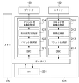
以下、本発明を実施するための最良の形態について図面を用いて説明する。図1に、本発明の一実施形態としての画像処理装置の全体ブロック図を示す。本発明の実施形態における画像処理装置はスキャン、プリント、コピーを行うMFP(Multi Functional Printer)を想定している。画像処理装置は、コントローラ101、スキャナ102、プリンタ103、通信IF104、メモリ105から構成されている。コントローラ101は、画像処理装置全体の制御を司る部分である。コントローラ101はスキャナ102やプリンタ103をはじめとする各ブロックと電気的に接続されており、高度な機能を実現する為の制御を行っている。詳細については後述する。
<First embodiment>
The best mode for carrying out the present invention will be described below with reference to the drawings. FIG. 1 shows an overall block diagram of an image processing apparatus as an embodiment of the present invention. The image processing apparatus according to the embodiment of the present invention is assumed to be an MFP (Multi Functional Printer) that performs scanning, printing, and copying. The image processing apparatus includes a
スキャナ102は原稿画像を光学的に読み取って電気的な画像信号に変換するブロックであり、密着型イメージセンサ(不図示)、読み取り駆動部(不図示)、読み取り点灯制御部(不図示)等により構成される。読み取り駆動部によって搬送される密着型イメージセンサによって原稿全体がスキャンされる際、読み取り点灯制御部によって密着型イメージセンサ内部のLEDが点灯制御される。同時に、密着型イメージセンサ内部のフォトセンサが原稿画像を光学的に読み取って、電気的な画像データに変換する。プリンタ103は電気的な画像信号を記録紙上に可視像としてプリントするブロックであり、レーザビームプリンタやインクジェットプリンタにより構成される。通信IF104は外部機器とのデータの送受を行うブロックであり、インターネット網やLANに接続したり、公衆電話回線に接続してFAX通信をおこなったり、USBインタフェースによりPC(Personal Computer)と接続する。メモリ105は、例えばDDR−SDRAMやHDDなどのメモリデバイスであり、画像データを一時的に格納するだけでなく、画像処理装置の機能を実現する為にコントローラ部が使用する制御プログラムやデータなどを格納する。
The
図2にコントローラ101のブロック図を示す。コントローラ101は、CPU(Central Processing Unit)201やスキャナ用画像処理部211、画像圧縮部212、パケット生成部213、DMAC(Direct Memory Access Controller)214、221、パケット展開部222、画像展開/回転部223、プリント用画像処理部224を含む。以下、各部の概略を説明する。CPU201はコントローラ部全体を制御する。スキャナ用画像処理部211はスキャナ102が読み込んだ画像データに対して、シェーディング補正等を施し、MTF補正、色変換処理、フィルタ処理、ガンマ処理等の各種画像処理を行う。その後、画像圧縮部212へ画像データを転送する。
FIG. 2 shows a block diagram of the
続いて、画像圧縮部212の詳細に関して説明を行う。まずページ単位のスキャナ用画像処理部211から受信した画像データから2×2画素のブロックを抽出し、そのブロック単位でデータの圧縮を行う。なお、2x2画素のブロックを最小単位として説明を進めるが、これに限るものではなく、必要に応じてブロックのサイズを変更してもよい。その際、以下で述べるデータのサイズ等は処理するブロックのサイズに応じて適時調整することとなる。
Next, details of the
[色パターン]
処理の説明の前に、2×2の4画素データ中に占める色の種類数である色数に応じて発生する組み合わせについて述べる。ここではブロックにおける画素数が4画素であるため、ブロック内に占める色数は最大4色になり、ブロック内では1〜4色の組み合わせしか存在しない。それら4色がとりうる組み合わせ(パターン)について図3を使って説明する。まずブロック内が1色の場合、4画素が同色で構成されている事になるので、その組み合わせは1通りである。次にブロック内が2色の場合を考える。2色が4画素内へレイアウトされる場合の数は、左上の画素を第1色、他方を第2色として考えると、左上以外残りの3画素へ第1色もしくは第2色が入るので、4画素同色の場合を除くと、全部で7通りの組み合わせが考えられる。次にブロック内が3色の場合を考える。3色が4画素内へレイアウトされる場合の数は、3色のうち1色だけ2度使われる場合の数と言い換える事が可能で、4画素の座標のうち、2画素が同じ色になる場合の数を求めればよい。つまり3色の場合の数は、4つの座標から2つの座標を取る組み合わせとなり、全部で6通りとなる。最後にブロック内が4色の場合は1色の場合と同様1パターンしか存在しない。これら1〜4色すべての場合の数を合計すると全部で15通りのパターンが考えられる。これらすべてのパターンを識別するためにフラグを対応付けて付与する事を考えると、データ量としては4bit必要となる。図示すると図4のようになり、以降これらのパターンに対応付けられたフラグをパターンフラグと呼ぶ。
[Color pattern]
Prior to the description of the processing, a combination that occurs in accordance with the number of colors that is the number of types of colors in 2 × 2 four-pixel data will be described. Here, since the number of pixels in the block is four, the maximum number of colors in the block is four, and there are only combinations of one to four colors in the block. The combinations (patterns) that these four colors can take will be described with reference to FIG. First, in the case of one color in the block, four pixels are configured in the same color, so there are only one combination. Next, consider the case where the block has two colors. Assuming that the two colors are laid out in four pixels, the first color or the second color enters the remaining three pixels other than the upper left, assuming that the upper left pixel is the first color and the other is the second color. Except for the case of four pixels having the same color, a total of seven combinations are possible. Next, consider a case where the block has three colors. The number of cases where three colors are laid out in four pixels can be rephrased as the number when only one of the three colors is used twice, and two of the four pixel coordinates have the same color. Find the number of cases. That is, the number in the case of three colors is a combination of taking two coordinates from four coordinates, and there are six ways in total. Finally, when there are four colors in the block, only one pattern exists as in the case of one color. When the numbers for all of these 1 to 4 colors are added up, 15 patterns can be considered in total. In consideration of assigning flags in association with each other to identify all these patterns, the data amount requires 4 bits. FIG. 4 shows the result, and the flags associated with these patterns are hereinafter referred to as pattern flags.
[画像圧縮処理]
上記のように2×2画素の取りうる組み合わせを踏まえて、画像圧縮部212にて行われる処理フローを、図5を用いて説明する。なお本実施形態において、入力としては、例えば色情報としてRGB(Red,Green,Blue)それぞれ8bitの256階調を有しており、またデータとしては8bitデータの点順次で1画素あたり24bit画像として説明を行う。しかし、この設定に限定されるものではなく、bit数に関しては必要に応じて変更してもよい。この場合、以下で説明するデータのサイズも異なってくることはいうまでも無い。
[Image compression processing]
Based on the possible combinations of 2 × 2 pixels as described above, a processing flow performed in the
まず2×2画素に分割されたブロックを入力する(S101)。そして、入力されたブロック内全ての2画素の組み合わせに対して、当該画素が有する24bitのコンペアを取る(S102)。このコンペアを取った結果、全ビット一致していた場合(すなわち、同一の画素値を有する場合)は1を出力し、不一致の場合は0を出力する。図6において、より具体的に示す。2×2画素からなるブロックの各画素において左上、右上、左下、右下の順に座標1、2、3、4とすると、2画素の組は、1−2、1−3、1−4、2−3、2−4、3−4の全部で6通りある。そのため、6回コンペアを取る必要があり、結果として6bitが出力される。例えば全画素同色の場合には、全てのコンペア結果が1を出力し、これに対し、4画素それぞれが異なる画素値を有している場合には、全てのコンペア結果が0を出力する。前述の通り、4画素で色の一致から出現しうるパターン数は15通りであるため、その6bitのコンペア結果に対して4bitのパターンフラグを割り当てて変換することが可能である(S103)。
First, a block divided into 2 × 2 pixels is input (S101). Then, for all combinations of two pixels in the input block, the 24-bit compare of the pixel is taken (S102). As a result of the comparison, when all the bits match (that is, when they have the same pixel value), 1 is output, and when they do not match, 0 is output. In FIG. 6, it shows more concretely. Assuming
4bitのパターンフラグへ変換した後、続いて4画素内で出現した色数および色画素データ(色情報)を抽出する(S104)。これにより、色取得、及び配置取得を行う。パターンフラグから、2x2画素のブロックにおける左上の画素の色を第1色とした場合の第2色以降がどの位置にあるかを求める事が出来る。なお、本実施形態においては、ブロックに含まれる画素数が4であるため、ブロックに含まれる色の数も最大4色となる。ブロックを構成する画素数が増加すれば、ブロックに含まれる最大色数も変化することとなる。 After the conversion to the 4-bit pattern flag, the number of colors appearing in the four pixels and the color pixel data (color information) are extracted (S104). Thereby, color acquisition and arrangement acquisition are performed. From the pattern flag, it is possible to determine the position of the second and subsequent colors when the color of the upper left pixel in the 2 × 2 pixel block is the first color. In the present embodiment, since the number of pixels included in the block is 4, the number of colors included in the block is also a maximum of four colors. If the number of pixels constituting the block increases, the maximum number of colors included in the block also changes.
ここで図7を参照して説明を行う。S104にて4画素内が1色で構成されていることが確定した場合には、S105にて1色(2色目以降は存在しない)であると判定する。なお、S105においては、抽出された色数が所定の数以上か否かを判定している(ここでは、単数色か否かを判定している)。そして、パターンフラグ4bitと1色目の24bitを出力する(S106)。同様に、S104にて4画素内が2色で構成されていることが確定した場合には、S107にて2色であると判定する。そして、2色目の画素値を有する画素の座標をパターンフラグより算出し、パターンフラグ4bitと2色分の画素値48bitを出力する(S108)。また、3色、4色で構成されている場合も同様の処理を行う(S109、S110、S111)。この時、ブロック内の画素の座標(左上、右上、左下、右下の順に1、2、3、4)の順にこれまで出現していなかった色データを記憶する。
Here, description will be given with reference to FIG. If it is determined in S104 that the four pixels are composed of one color, it is determined in S105 that there is one color (the second and subsequent colors do not exist). In S105, it is determined whether or not the number of extracted colors is equal to or greater than a predetermined number (in this case, it is determined whether or not there is a single color). Then, the
このように、2×2画素からなるブロック内の4色96bitの入力データを4bitのパターンフラグとそこに存在する色数分だけ画素値を取得し出力することで、比較的簡単な処理で出力データ量を削減することが可能になる。またパターンフラグを参照することで、そのブロック内の色数を特定することが可能になる。さらには、パターンフラグと色の記憶順により、ブロックに含まれる各画素が有する画素値を特定することができる。この処理を画像ブロック全てに対して行うことで、画像全面のデータ圧縮が可能になる。 In this way, the input data of 4 colors and 96 bits in a block of 2 × 2 pixels is output with relatively simple processing by acquiring and outputting the pixel values for the number of colors that are present in the 4-bit pattern flag. The amount of data can be reduced. In addition, by referring to the pattern flag, the number of colors in the block can be specified. Furthermore, the pixel value of each pixel included in the block can be specified by the order of storing the pattern flag and the color. By performing this process for all image blocks, data compression of the entire image becomes possible.
[ヘッダ情報]
パケット生成部213は、画像圧縮部212により圧縮された画像データを所定の大きさの単位(本実施形態では32×32画素とし、この単位をタイルと呼ぶ)で読み出し、タイルに所定の固定長のヘッダ情報を付与する。図8にタイルとブロックとの関係を示す。
[Header information]
The
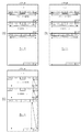
ヘッダにはページID、タイル座標、色空間、画素データのビット数、タイルのデータサイズ、回転角度情報等の情報を記述する。図9にタイルに付与されたヘッダ情報の構成例を示す。ページIDには、ページ単位にユニークなID番号を付与する。タイル座標には、そのタイルがページ単位のラスタ画像上どの位置にあるかを記述してある。ここには、X座標とY座標と2次元で座標が示されているとする。色空間には、そのタイルがRGB画像なのかCMYK画像なのかGRAY−SCALE画像なのかの識別子が記述されている。画素データのビット数には、タイル内の1画素あたりのビット長が書かれている。データサイズには、そのタイルの第2、3、4色画素データのデータサイズがByte単位で記述されている。回転角度情報には、画像の回転角度の情報が含まれており、時計回りに0°、90°、180°、270°のいずれかの角度になる。なお、ヘッダ情報はこの構成に限定されるものではない。また、回転角度の情報は、回転する単位(例えば、ページ単位、タイル単位)にて保持してもよい。 In the header, information such as page ID, tile coordinates, color space, number of bits of pixel data, tile data size, and rotation angle information is described. FIG. 9 shows a configuration example of the header information given to the tile. A unique ID number is assigned to each page ID. The tile coordinates describe where the tile is on the raster image in page units. Here, it is assumed that coordinates are shown in two dimensions, an X coordinate and a Y coordinate. The color space describes an identifier of whether the tile is an RGB image, a CMYK image, or a GRAY-SCALE image. In the bit number of pixel data, the bit length per pixel in the tile is written. In the data size, the data size of the second, third, and fourth color pixel data of the tile is described in units of bytes. The rotation angle information includes information on the rotation angle of the image, and is any one of 0 °, 90 °, 180 °, and 270 ° in the clockwise direction. The header information is not limited to this configuration. Further, the information on the rotation angle may be held in a rotating unit (for example, a page unit or a tile unit).
以後このタイルの情報とヘッダ情報とを含めたデータの単位をパケットと呼ぶことにする。パケットのデータ構造の作り方について述べる。画像圧縮部212で生成されるデータは大きくパターンフラグ・第1色画素データ・第2、3、4色画素データの3つのデータ種に分類可能である。各データのサイズは、タイルの単位である32×32画素のRGB各色8ビット画像の場合、以下のようになる。
Hereinafter, a unit of data including the tile information and the header information is referred to as a packet. Describes how to create a packet data structure. Data generated by the
パターンフラグ(各ブロック4bit):4×16×16/8=128Byte
第1色のデータサイズ(各ブロック24bit):24×16×16/8=768Byte
第2、3、4色のデータサイズ(各ブロック最大72bit):最大72×16×16/8=最大2304Byte(画像によって異なる)
これらのデータサイズを格納可能な記憶部(不図示)をパケット生成部213に用意しておき、データ種ごと領域をまとめて格納する。タイル単位で圧縮処理が終了しデータサイズが確定した後ヘッダを付加することで、図9のようなパケットのデータ構造を作ることができる。
Pattern flag (4 bits for each block): 4 × 16 × 16/8 = 128 bytes
Data size of the first color (each
Data size of second, third, and fourth colors (maximum 72 bits for each block): maximum 72 × 16 × 16/8 = maximum 2304 bytes (depending on the image)
A storage unit (not shown) capable of storing these data sizes is prepared in the
ここで第1色画素データ以降のメモリ領域に関しては、画素データがピクセル単位で量子化や符号化されることなく格納されている。つまり、1画素入力、1画素出力で完結する色処理、例えばLUTを用いた色変換や、ガンマ補正処理、行列演算を用いた色空間変換処理等は特にパターンフラグを参照する必要はなく、直接処理を行うことが可能になる。このように圧縮データを直接用いることで、メモリバス上の転送効率が向上し、かつオリジナルの画像に対して少ない画素数のデータに対して処理することになるので、高速処理が可能になる。 Here, with respect to the memory area after the first color pixel data, the pixel data is stored without being quantized or encoded in units of pixels. That is, color processing that is completed with one pixel input and one pixel output, for example, color conversion using LUT, gamma correction processing, color space conversion processing using matrix operation, etc., do not need to refer to the pattern flag directly. Processing can be performed. By directly using the compressed data in this way, the transfer efficiency on the memory bus is improved and the original image is processed with respect to data having a small number of pixels, so that high-speed processing is possible.
また前述のように(図9のように)画像データをメモリ上へ格納することで、第1色画素データ領域は、画像を2×2画素単位における左上の座標の画素をサンプリングした画像結果がメモリ上に連続して存在することになる。本実施形態で説明している画像処理装置においては、蓄積したPDL(Page Description Language)画像データやスキャンの画像データのプレビュー表示や、前述したネットワーク送信などの機能も有している。例えばプリント解像度が600dpiであったとしてもプレビューや送信時にそこまでの解像度は通常必要とされず、300dpiやそれ以下で十分な場合が多い。こういった縮小データを得る必要がある場合は、パターンフラグや第2、3、4色を用いず、第1色の画像データのみ扱うことで、簡単に半分のサイズのラスタ画像を得る事が出来る。 Further, as described above (as shown in FIG. 9), by storing the image data in the memory, the first color pixel data area is obtained by sampling the image of the pixel at the upper left coordinate in the 2 × 2 pixel unit. It exists continuously on the memory. The image processing apparatus described in the present embodiment also has functions such as preview display of accumulated PDL (Page Description Language) image data and scan image data, and network transmission described above. For example, even if the print resolution is 600 dpi, the resolution up to that is usually not required at the time of preview or transmission, and 300 dpi or less is often sufficient. When it is necessary to obtain such reduced data, a raster image having a half size can be easily obtained by using only the first color image data without using the pattern flag or the second, third, and fourth colors. I can do it.
タイルの座標とサイズ、パケットが格納されているアドレスをリストとして列挙し、パケット管理テーブルとして作成することで、任意のパケットへのアクセスが可能になる。パケット管理テーブルの例を図10に示す。このようにしてタイル単位で画像をパケットとしてメモリへ書き出すと図11のようにパケット毎にサイズが異なり、それぞれのパケットの先頭アドレスがとびとびになってしまう。そのためパケット管理テーブルを用いて、任意の座標のパケットに対する先頭アドレスを探索する。このようにタイル単位に任意のデータへのアクセスが可能になるので、画像の部分的な処理が可能になる。 By enumerating the coordinates and sizes of tiles and addresses where packets are stored as a list and creating a packet management table, it is possible to access any packet. An example of the packet management table is shown in FIG. When the image is written in the memory as a packet in the tile unit in this way, the size is different for each packet as shown in FIG. 11, and the leading address of each packet becomes discrete. Therefore, the start address for a packet with an arbitrary coordinate is searched using the packet management table. As described above, since arbitrary data can be accessed in tile units, partial processing of an image becomes possible.
さらに、パケット生成部213は生成したパケットをDMAC214に転送する。DMAC214、221は、画像データのメモリ106からの転送を制御するDMA(Direct Memory Access)機能を有している。パケット展開部222は、DMAC221からパケットを受信する。さらにパケットのヘッダから取得した回転角度情報とパターンフラグ・第1色画素データ・第2、3、4色画素データそれぞれを画像展開/回転部223に送出する。
Further, the
ここで画像展開/回転部223における処理の流れに関して説明する。画像展開/回転部223では前述したようなパターンフラグ、画素データに基づいてラスタ画像データへ戻す処理を行う。図12に画像展開/回転部223で行われる処理のフローチャートを示す。画像展開/回転部223ではまずパケット展開部222から転送されたデータのうち、回転角度情報を読み出す(S201)。そして、読み出した回転角度に応じたブロック読み出し順序を決定する(S202)。さらに、ブロック読み出し順序と同じ順序でパターンフラグを読み出す(S203)。さらに、回転角度とパターンフラグから第1色の位置を判断する(S204)。そして、回転角度情報に応じて第1色画素データを読み出す(S205)。続いて、回転角度とパターンフラグから第2,3,4色の位置を判断する(S206)。そして、色数に応じた第2、3、4色画素データを読み出す(S207)。さらに、パターンフラグにより定まる色の配置と第1色画素の位置に応じて画素データを配置する(S208)。このようにすることにより、2×2画素からなるブロックを展開、そして復号する。より具体的な処理方法に関しては図17等を用いて後述する。
Here, the flow of processing in the image development /
プリント用画像処理部224はスキャナ用画像処理された画像データに対して2値化処理、中間調処理、そしてRGBtoCMYK等色変換処理等を行い中間調画像に変換する。さらに、記録解像度にあわせて解像度変換し、画像の変倍、スムージング、濃度補正等の各種画像処理を施して高精細な画像データに変換し、レーザビームプリンタ等に出力する。
The print
[画像処理フロー]
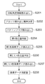
図13は、第一の実施形態における画像処理装置の動作を示すフローチャートである。第一の実施形態では、画像データがスキャナから読み込まれて時計回りに90°の回転処理が行われプリンタに出力されるまでを述べる。特に画像展開/回転部223の動作に関して詳述する。ここでの画像データのサイズは、例として64×96画素、パケット生成時のタイルの大きさは32×32画素とする。スキャナ102においてRGB3色の画像データの読み取りを行う(S301)。次に、コントローラ101のスキャナ用画像処理部211にてシェーディング処理やフィルタ処理等の画像処理を行う(S302)。そして、画像圧縮部212にて画像圧縮処理を行う(S303)。その圧縮データをパケット生成部213にてパケットに変換して生成する(S304)。その後、DMAC214を介してメモリ105へ格納して保持する(S305)。図14(A)にタイル座標(0,0)で表されるパケットのデータ構造を示す。メモリへの格納後、CPU201によりパケット管理テーブルの更新が行われる(S306)。ここで、更新される前のパケット管理テーブルを図15(A)に、そして、パケットの配置概略図を図16(A)に示す。また、更新された後の時計回りに90°回転したパケット管理テーブルを図15(B)に、そして、パケットの配置概略図を図16(B)に示す。
[Image processing flow]
FIG. 13 is a flowchart showing the operation of the image processing apparatus according to the first embodiment. In the first embodiment, a process from when image data is read from a scanner to 90 ° clockwise and output to a printer will be described. In particular, the operation of the image development /
S306にてパケット管理テーブルを更新した後、CPU201により全てのパケットのヘッダが有する回転角度情報を0°から90°に書き換える(S307)。図14(B)にパケット管理テーブルの更新とヘッダ内の回転角度情報の書き換えが終了した時点における、タイル座標(0,0)で表されるパケットのデータ構造を示す。次に全てのパケットの回転角度情報が書き換えられているか判定し(S308)、書き換えられていればパケット管理テーブルに従って、メモリ105に格納され、保持しているパケットデータを、DMAC221を介して読み込む(S309)。具体的には、更新されたパケット管理テーブルのパケット(0,0)から順番にアドレスを指定し読み出しを行う。なお、S308にて全ての書き換えが終了していないと判定された場合には、S307へ戻り、回転角度情報の書き換えが全てのブロックへ適用されるまで繰り返される。次に、パケット展開部222でパケットの展開が行われる(S310)。さらに、画像展開/回転部223にてラスタ画像データへ展開しながら回転を行う(S311)。ラスタの画像データをプリント用画像処理部224に入力し、そこでディザ法や誤差拡散法による面積階調処理を行う(S312)。これにより、画像データを形成し、プリンタ103へ出力する(S313)。
After updating the packet management table in S306, the
[画像回転/回転処理]
続いて、画像展開/回転部223における処理(S311)の詳細について述べる。図17は第一の実施形態の図13におけるS311の詳細を示したフローチャートである。まず、画像展開/回転部223は、回転角度情報を読み出す(S401)。次に、回転角度情報に応じたブロックの読み出し順序を決定する(S402)。タイル内のブロックにX座標とY座標で示される二次元のブロック座標を与えると、回転角度0°では、ブロック座標(0,0)から(1,0)、(2,0)・・・の順でブロックを読み出し、処理する。図18(A)に、回転角度0°の時のブロック読み出し順序を示す。一方、回転角度90°の場合、ブロック座標(0,15)から(0,14)、(0,13)・・・の順でブロックを読み出し、処理する。図18(B)に、回転角度90°の時のブロック読み出し順序を示す。次に、S402で決定したブロック読み出し順序に従い、パターンフラグを読み出す(S403)。図19(A)に回転角度0°におけるメモリ配置されたパケットのパターンフラグの読み出し順序を示す。図19(B)に回転角度90°におけるメモリ配置されたパケットのパターンフラグの読み出し順序を示す。次に、回転角度情報とパターンフラグより第1色がブロックのどの位置に該当するかを判断する(S404)。回転角度が0°の場合、第1色の位置はブロックの左上画素であるため、回転角度が90°では、第1色の位置はブロックの右上画素になる。
[Image rotation / rotation processing]
Next, details of the processing (S311) in the image development /
次に、回転角度情報に応じたブロックの第1色画素データを読み出す(S405)。図19(A)に回転角度0°の時、そして、図19(B)に回転角度90°の時のメモリ配置されたパケットの第1色画素データの読み出し順序を示す。続いて、S403で読み出したパターンフラグにより、処理中のブロックに第2,3,4色が存在するか判定し(S406)、存在する場合、S404で判断した第1色の位置とパターンフラグより第2,3,4色の位置を判断する(S407)。次に、回転角度情報とパターンフラグに応じてブロックの第2,3,4色画素データを読み出す(S408)。パターンフラグによっては、第2,3,4色画素データが存在しないブロックもあるため、パターンフラグを用いて第2,3,4色画素データを読み出すか否かを判断する必要がある。図19(A)に回転角度0°の時、図19(B)に回転角度90°の時の、メモリ配置されたパケットの第2,3,4色画素データの読み出し順序を示す。 Next, the first color pixel data of the block corresponding to the rotation angle information is read (S405). FIG. 19A shows the reading order of the first color pixel data of the packets arranged in the memory when the rotation angle is 0 ° and FIG. 19B shows the rotation angle of 90 °. Subsequently, it is determined whether the second, third, and fourth colors exist in the block being processed based on the pattern flag read in S403 (S406). If present, the position of the first color determined in S404 and the pattern flag are determined. The positions of the second, third, and fourth colors are determined (S407). Next, the second, third, and fourth color pixel data of the block are read according to the rotation angle information and the pattern flag (S408). Depending on the pattern flag, there are some blocks in which the second, third, and fourth color pixel data do not exist. Therefore, it is necessary to determine whether to read the second, third, and fourth color pixel data using the pattern flag. FIG. 19A shows the reading order of the second, third, and fourth color pixel data of the memory-arranged packet when the rotation angle is 0 ° and FIG. 19B is the rotation angle 90 °.
次に、S404で判断した第1色の位置にS405で読み出した第1色画素データを、S407で判断した第2,3,4色の位置にS408で読み出した第2,3,4色画素データを配置する(S409)。S406にて第2,3,4色が存在しないと判定された場合は、S404で判断した第1色の位置にS405で読み出した第1色画素データで配置を行う(S409)。パターンフラグの値が“A”の場合(すなわち、色数は第1から第3までの3色)の具体例を示す。回転角度が90°では、第1色の位置は右上画素であり、右下、左上、左下の順で第2,第3の色データは格納されている。そのため、右下が第2色・左上と左下が第3色となる。以上述べた原理により、画素データの配置を行う。全てのブロックに対して処理が終了したかを判定し(S409)、終了していればデータをプリント用画像処理部224に転送する。もちろん、各ブロックの画像展開/回転終了毎にプリント用画像処理部224に転送してもよい。S410にて全てのブロックに対する処理が終了していないと判定された場合には、S403へ戻り、全てのブロックに対して本処理が終了するまで繰り返す。図20(A)に回転処理を終えた画像の全体図を示す。
Next, the first color pixel data read in S405 at the first color position determined in S404, and the second, third, and fourth color pixels read in S408 in the second, third, and fourth color positions determined in S407. Data is arranged (S409). If it is determined in S406 that the second, third, and fourth colors do not exist, the first color pixel data read in S405 is arranged at the position of the first color determined in S404 (S409). A specific example in the case where the value of the pattern flag is “A” (that is, the number of colors is three colors from first to third) is shown. When the rotation angle is 90 °, the position of the first color is the upper right pixel, and the second and third color data are stored in the order of lower right, upper left, and lower left. Therefore, the lower right is the second color, and the upper left and lower left are the third color. Pixel data is arranged according to the principle described above. It is determined whether processing has been completed for all blocks (S409). If completed, the data is transferred to the print
以上説明してきた構成をとることで、比較的単純な圧縮方式を用い、圧縮された状態で画像データを回転可能となる。これにより、展開した後の画像データに対し回転処理を適用するよりも高速演算器もしくは専用ハードウェアやバッファ用のメモリが必要とする量が削減でき、安価な画像処理装置の提供が可能である。バッファ用のメモリを例に取り具体的な効果を述べる。バッファ用のメモリの容量と処理パフォーマンスは比例関係にあるため、例えばRGB各8ビット、32×32画素のバッファ用のメモリを用意した場合では、32×32×8×3=24KByteのメモリが削減できる。なお本実施形態では2×2画素からなるブロックを最小単位として記述していたが、これに限るものではない。また圧縮の説明の際画像データとしてRGB8bitを例として説明していたが、CMYKの色空間を取るものや、GRAYスケールのデータ、また8bit以外の画素値をとるものでも良い。
With the configuration described above, it is possible to rotate image data in a compressed state using a relatively simple compression method. As a result, it is possible to reduce the amount required for a high-speed arithmetic unit, dedicated hardware, or buffer memory, and to provide an inexpensive image processing apparatus, compared to applying rotation processing to the developed image data. . Specific effects will be described by taking a buffer memory as an example. Since the capacity of the buffer memory and the processing performance are in a proportional relationship, for example, when a buffer memory of 8 bits for RGB and 32 × 32 pixels is prepared, the memory of 32 × 32 × 8 × 3 = 24 KB is reduced. it can. In the present embodiment, a block composed of 2 × 2 pixels is described as the minimum unit, but the present invention is not limited to this. In the description of compression,
<第二の実施形態>
以下、添付図面を参照して、本発明の第二の実施形態について詳細に説明する。本実施形態では画像展開/回転部の別実施形態を説明する。本発明の第二の実施形態における画像処理装置の構成は図1と、コントローラ101の構成は図2と同一である。ただし、画像展開/回転部223内に更新前のパターンフラグと第1色の位置と、回転角度に応じて更新したパターンフラグと第1色の位置と第2,3,4色の位置の情報を記憶する手段(回転位置保持手段)を設けている。そこで図21に回転角度90°、180°、270°の時の回転前と回転後の位置関係を示す。ここで図21にて示した回転前と回転後の情報を位置情報と呼ぶ。本実施形態では、更新した後の色の位置はパターンフラグを参照した際の第1色から第4色まで色のうち、いずれの位置と等しいかを示している。
<Second Embodiment>
Hereinafter, a second embodiment of the present invention will be described in detail with reference to the accompanying drawings. In the present embodiment, another embodiment of the image development / rotation unit will be described. The configuration of the image processing apparatus according to the second embodiment of the present invention is the same as that shown in FIG. 1, and the configuration of the
本実施形態における画像処理装置の動作を示すフローチャートは、図13とほぼ同一である。第二の実施形態では、画像データがスキャナから読み込まれて時計回りに270°の回転処理が行われプリンタに出力されるまでを述べる。特に画像展開/回転部223の動作に関して詳述する。ここで、画像データのサイズは64×96画素、パケット生成時のタイルの大きさは32×32画素とする。図13のフローチャートにおいて、処理内容に第一の実施形態との差分がある。差分として、S306におけるCPU201によるパケット管理テーブルの更新と、S307におけるCPU201による全てのパケットのヘッダの回転角度情報を0°から270°への書き換えである。更新された後の時計回りに270°回転したパケット管理テーブルを図15(C)に、パケットの配置概略図を図16(C)に示す。図14(C)にパケット管理テーブルの更新とヘッダ内の回転角度情報の書き換えが終了した時点の、タイル座標(0,0)で表されるパケットのデータ構造を示す。第二の実施形態では、時計回りに270°回転を行うための、変更が行われる。
A flowchart showing the operation of the image processing apparatus in the present embodiment is almost the same as FIG. In the second embodiment, a process from when image data is read from a scanner to when it is rotated clockwise by 270 ° and output to a printer will be described. In particular, the operation of the image development /
[画像展開/回転処理]
以下、画像展開/回転部223における処理(S311)の詳細について述べる。図22は第二の実施形態の図13におけるS311に対応する処理の詳細を示したフローチャートである。まず、画像展開/回転部223は、回転角度情報を読み出す(S501)。次に、回転角度情報に応じたブロックの読み出し順序を決定する(S502)。回転角度270°の場合、ブロック座標(15,0)から(15,1)、(15,2)・・・の順でブロックを読み出し、処理する。図18(C)に、回転角度270°の時のブロック読み出し順序を示す。次に、S402で決定したブロック読み出し順序に従い、パターンフラグを読み出す(S503)。図19(C)に回転角度270°におけるメモリ配置されたパケットのパターンフラグの読み出し順序を示す。次に、回転角度に応じてパターンフラグと第1色の位置と第2,3,4色の位置を更新する(S504)。次に、回転角度情報に応じたブロックの第1色画素データを読み出す(S505)。続いて、S504で更新したパターンフラグより、処理中のブロックに第2,3,4色が存在するか否かを判定する(S506)。第2,3,4色が存在する場合、第2,3,4色画素データを読み出す(S507)。パターンフラグによっては、第2,3,4色画素データが存在しないブロックもあるため、パターンフラグを用いて第2,3,4色画素データを読み出すか否かを判定する必要がある。
[Image expansion / rotation processing]
Details of the processing (S311) in the image development /
図19(C)に回転角度270°の時のメモリ配置されたパケットの第2,3,4色画素データの読み出し順序を示す。次に、S504で更新した第1色の位置と第2,3,4色の位置からS505で読み出した第1色画素データとS508で読み出した第2,3,4色画素データを配置する(S508)。S506にて第2,3,4色が存在しないと判定された場合は、S504で更新したパターンフラグと第1色の位置にS505で読み出した第1色画素データで配置を行う(S508)。パターンフラグの値が“B”の場合(すなわち、色数は第1から第3までの3色)の具体例を示す。図21に示すように、パターンフラグが“B”で回転角度が270°の場合、回転後のパターンフラグは9であり、第1色の位置は左下に位置する画素である。さらに、左上、右下、右上の順で第2,3,4色データは格納されているため、左上と右下が第2色となり、右上が第3色となる。以上述べた方法により、位置情報を用いて画素データの配置を行う。全てのブロックに対して処理が終了したかを判定し(S509)、終了していればデータをプリント用画像処理部224に転送する。もちろん、各ブロックの画像展開/回転終了毎にプリント用画像処理部224に転送してもよい。S509にて全てのブロックが終了していないと判定された場合には、S503へ戻り、全てのブロックに対し本処理が終了するまで処理を繰り返す。図20(B)に回転処理を終えた画像の全体図を示す。
FIG. 19C shows the reading order of the second, third, and fourth color pixel data of the packet arranged in the memory when the rotation angle is 270 °. Next, the first color pixel data read in S505 and the second, third, and fourth color pixel data read in S508 from the first color position and the second, third, and fourth color positions updated in S504 are arranged ( S508). If it is determined in S506 that the second, third, and fourth colors do not exist, the pattern flag updated in S504 and the first color pixel data read in S505 are arranged at the position of the first color (S508). A specific example in the case where the value of the pattern flag is “B” (that is, the number of colors is three colors from the first to the third) is shown. As shown in FIG. 21, when the pattern flag is “B” and the rotation angle is 270 °, the rotated pattern flag is 9, and the position of the first color is a pixel located in the lower left. Furthermore, since the second, third, and fourth color data are stored in the order of upper left, lower right, and upper right, the upper left and lower right become the second color, and the upper right becomes the third color. The pixel data is arranged using the position information by the method described above. It is determined whether processing has been completed for all blocks (S509). If completed, the data is transferred to the print
なお本実施形態では2×2画素からなるブロックを最小単位として記述していたが、これに限るものではない。また圧縮の説明の際画像データとしてRGB8bitを例として説明していたが、CMYKの色空間を取るものや、GRAYスケールのデータ、また8bit以外の画素値をとるものでも良い。また、ブロックのサイズを変更した場合には、フラグパターンや扱う色の数も増減することは言うまでも無い。
In the present embodiment, a block composed of 2 × 2 pixels is described as the minimum unit, but the present invention is not limited to this. In the description of compression,
以上説明してきた構成をとることで、比較的単純な圧縮方式を用い、圧縮された状態で画像データを回転可能となる。これにより、展開した後の画像データに対し回転処理を適用するよりも高速演算器もしくは専用ハードウェアやバッファ用のメモリが必要とする量が削減でき、安価な画像処理装置の提供が可能である。 With the configuration described above, it is possible to rotate image data in a compressed state using a relatively simple compression method. As a result, it is possible to reduce the amount required for a high-speed arithmetic unit, dedicated hardware, or buffer memory, and to provide an inexpensive image processing apparatus, compared to applying rotation processing to the developed image data. .
<その他の実施形態>
また、本発明は、以下の処理を実行することによっても実現される。即ち、上述した実施形態の機能を実現するソフトウェア(プログラム)を、ネットワーク又は各種記憶媒体を介してシステム或いは装置に供給し、そのシステム或いは装置のコンピュータ(またはCPUやMPU等)がプログラムを読み出して実行する処理である。
<Other embodiments>
The present invention can also be realized by executing the following processing. That is, software (program) that realizes the functions of the above-described embodiments is supplied to a system or apparatus via a network or various storage media, and a computer (or CPU, MPU, or the like) of the system or apparatus reads the program. It is a process to be executed.
Claims (13)
前記画像データの回転角度を記憶する記憶手段と、
前記画像データにおいて、所定の数の画素からなるブロックにより構成されるタイルごとに、圧縮することによって得られた前記ブロックにおける色の配置の情報と、前記色の配置に対応する色情報と、前記画像データにおける当該タイルの位置の情報とを保持する保持手段と、
前記記憶手段にて記憶した当該画像データの回転角度に応じて前記ブロックにおける色の配置を変換し、変換された色の配置、配置に対応する色情報、及び前記タイルの位置の情報から回転後の画像データを形成する回転手段と
を有することを特徴とする画像処理装置。 An image processing apparatus capable of rotating input image data in a compressed state,
Storage means for storing a rotation angle of the image data;
In the image data, for each tile constituted by a block composed of a predetermined number of pixels, information on the color arrangement in the block obtained by compression, color information corresponding to the color arrangement, and Holding means for holding information on the position of the tile in the image data;
The color arrangement in the block is converted according to the rotation angle of the image data stored in the storage means, and the converted color arrangement, the color information corresponding to the arrangement, and the tile position information are rotated. An image processing apparatus comprising: a rotation unit that forms the image data.
前記ブロックにおけるの色の配置、及び前記色の配置に対応する色情報とを取得し、前記画像データを圧縮する取得手段と
を更に有することを特徴とする請求項1に記載の画像処理装置。 A dividing unit that divides the input image data into blocks each including a predetermined number of pixels;
The image processing apparatus according to claim 1, further comprising an acquisition unit configured to acquire a color arrangement in the block and color information corresponding to the color arrangement and compress the image data.
前記画像データの回転角度を記憶する記憶手段と、
前記画像データにおいて、所定の数の画素からなるブロックにより構成されるタイルごとに、圧縮することによって得られた前記ブロックにおける色の配置の情報と、前記色の配置に対応する色情報と、前記画像データにおける当該タイルの位置の情報とを保持する保持手段と、
前記画像データの回転角度に応じた回転前と回転後との色の配置に対応する位置情報を保持する回転位置保持手段と、
前記回転位置保持手段にて保持する位置情報に応じて回転後の対応する色の配置と色情報とを用いて回転後の画像データを形成する回転手段と
を有することを特徴とする画像処理装置。 An image processing apparatus capable of rotating input image data in a compressed state,
Storage means for storing a rotation angle of the image data;
In the image data, for each tile constituted by a block composed of a predetermined number of pixels, information on the color arrangement in the block obtained by compression, color information corresponding to the color arrangement, and Holding means for holding information on the position of the tile in the image data;
Rotation position holding means for holding position information corresponding to the arrangement of colors before and after rotation according to the rotation angle of the image data;
An image processing apparatus comprising: rotation means for forming image data after rotation using the corresponding color arrangement and color information after rotation according to position information held by the rotation position holding means .
前記画像処理装置の記憶手段が、前記画像データの回転角度を記憶する記憶工程と、
前記画像処理装置の保持手段が、前記画像データにおいて、所定の数の画素からなるブロックにより構成されるタイルごとに、圧縮することによって得られた前記ブロックにおける色の配置の情報と、前記色の配置に対応する色情報と、前記画像データにおける当該タイルの位置の情報とを保持する保持工程と、
前記画像処理装置の回転手段が、前記記憶手段にて記憶した当該画像データの回転角度に応じて前記ブロックにおける色の配置を変換し、変換された色の配置、配置に対応する色情報、及び前記タイルの位置の情報から回転後の画像データを形成する回転工程と
を特徴とする制御方法。 A control method of an image processing apparatus that enables input image data to be rotated in a compressed state,
A storage step in which the storage means of the image processing apparatus stores the rotation angle of the image data;
In the image data, the holding unit of the image processing apparatus compresses, for each tile configured by a block including a predetermined number of pixels, information on the color arrangement in the block obtained by compression, and the color A holding step for holding color information corresponding to the arrangement and information on the position of the tile in the image data;
The rotation means of the image processing device converts the color arrangement in the block according to the rotation angle of the image data stored in the storage means, and the converted color arrangement, color information corresponding to the arrangement, and A rotation step of forming rotated image data from the tile position information.
前記画像処理装置の記憶手段が、前記画像データの回転角度を記憶する記憶工程と、
前記画像処理装置の保持手段が、前記画像データにおいて、所定の数の画素からなるブロックにより構成されるタイルごとに、圧縮することによって得られた前記ブロックにおける色の配置の情報と、前記色の配置に対応する色情報と、前記画像データにおける当該タイルの位置の情報とを保持する保持工程と、
前記画像処理装置の回転位置保持手段が、前記画像データの回転角度に応じた回転前と回転後との色の配置に対応する位置情報を保持する回転位置保持工程と、
前記画像処理装置の回転手段が、前記回転位置保持工程において保持する位置情報に応じて回転後の対応する色の配置と色情報とを用いて回転後の画像データを形成する回転工程と
を有することを特徴とする制御方法。 A control method of an image processing apparatus that enables input image data to be rotated in a compressed state,
A storage step in which the storage means of the image processing apparatus stores the rotation angle of the image data;
In the image data, the holding unit of the image processing apparatus compresses, for each tile configured by a block including a predetermined number of pixels, information on the color arrangement in the block obtained by compression, and the color A holding step for holding color information corresponding to the arrangement and information on the position of the tile in the image data;
A rotational position retaining step in which the rotational position retaining means of the image processing apparatus retains positional information corresponding to the color arrangement before and after the rotation according to the rotational angle of the image data;
The rotation unit of the image processing apparatus includes a rotation step of forming image data after rotation using the corresponding color arrangement and color information after rotation according to the position information held in the rotation position holding step. A control method characterized by that.
画像データの回転角度を記憶する記憶手段、
前記画像データにおいて、所定の数の画素からなるブロックにより構成されるタイルごとに、圧縮することによって得られた前記ブロックにおける色の配置の情報と、前記色の配置に対応する色情報と、前記画像データにおける当該タイルの位置の情報とを保持する保持手段、
前記記憶手段にて記憶した当該画像データの回転角度に応じて前記ブロックにおける色の配置を変換し、変換された色の配置、配置に対応する色情報、及び前記タイルの位置の情報から回転後の画像データを形成する回転手段
として機能させるためのプログラム。 Computer
Storage means for storing the rotation angle of the image data;
In the image data, for each tile constituted by a block composed of a predetermined number of pixels, information on the color arrangement in the block obtained by compression, color information corresponding to the color arrangement, and Holding means for holding information on the position of the tile in the image data;
The color arrangement in the block is converted according to the rotation angle of the image data stored in the storage means, and the converted color arrangement, the color information corresponding to the arrangement, and the tile position information are rotated. For causing the image data to function as rotating means.
画像データの回転角度を記憶する記憶手段、
前記画像データにおいて、所定の数の画素からなるブロックにより構成されるタイルごとに、圧縮することによって得られた前記ブロックにおける色の配置の情報と、前記色の配置に対応する色情報と、前記画像データにおける当該タイルの位置の情報とを保持する保持手段、
前記画像データの回転角度に応じた回転前と回転後との色の配置に対応する位置情報を保持する回転位置保持手段、
前記回転位置保持手段にて保持する位置情報に応じて回転後の対応する色の配置と色情報とを用いて回転後の画像データを形成する回転手段
として機能させるためのプログラム。 Computer
Storage means for storing the rotation angle of the image data;
In the image data, for each tile constituted by a block composed of a predetermined number of pixels, information on the color arrangement in the block obtained by compression, color information corresponding to the color arrangement, and Holding means for holding information on the position of the tile in the image data;
Rotation position holding means for holding position information corresponding to the color arrangement before and after rotation according to the rotation angle of the image data;
A program for functioning as rotating means for forming image data after rotation using the corresponding color arrangement and color information after rotation according to position information held by the rotation position holding means.
Priority Applications (2)
| Application Number | Priority Date | Filing Date | Title |
|---|---|---|---|
| JP2010058299A JP5501041B2 (en) | 2010-03-15 | 2010-03-15 | Image processing apparatus, image processing method, and program |
| US13/023,215 US8953220B2 (en) | 2010-03-15 | 2011-02-08 | Image processing for rotation of compressed image data |
Applications Claiming Priority (1)
| Application Number | Priority Date | Filing Date | Title |
|---|---|---|---|
| JP2010058299A JP5501041B2 (en) | 2010-03-15 | 2010-03-15 | Image processing apparatus, image processing method, and program |
Publications (3)
| Publication Number | Publication Date |
|---|---|
| JP2011193279A JP2011193279A (en) | 2011-09-29 |
| JP2011193279A5 JP2011193279A5 (en) | 2013-05-02 |
| JP5501041B2 true JP5501041B2 (en) | 2014-05-21 |
Family
ID=44559698
Family Applications (1)
| Application Number | Title | Priority Date | Filing Date |
|---|---|---|---|
| JP2010058299A Expired - Fee Related JP5501041B2 (en) | 2010-03-15 | 2010-03-15 | Image processing apparatus, image processing method, and program |
Country Status (2)
| Country | Link |
|---|---|
| US (1) | US8953220B2 (en) |
| JP (1) | JP5501041B2 (en) |
Families Citing this family (8)
| Publication number | Priority date | Publication date | Assignee | Title |
|---|---|---|---|---|
| JP5393574B2 (en) * | 2010-04-08 | 2014-01-22 | キヤノン株式会社 | Image processing apparatus, image processing method, and program |
| JP5538996B2 (en) | 2010-04-30 | 2014-07-02 | キヤノン株式会社 | Image processing apparatus, image processing method, program, and storage medium |
| JP2012010088A (en) | 2010-06-24 | 2012-01-12 | Canon Inc | Image processing apparatus, control method, and program |
| JP5595151B2 (en) | 2010-07-13 | 2014-09-24 | キヤノン株式会社 | Image processing apparatus, compression method in image processing apparatus, and program |
| JP5643574B2 (en) | 2010-08-26 | 2014-12-17 | キヤノン株式会社 | Image processing apparatus and image processing method |
| EP2754712B1 (en) | 2011-09-05 | 2017-10-04 | Toray Industries, Inc. | Mutant endoglucanase |
| JP6070524B2 (en) * | 2013-12-04 | 2017-02-01 | ソニー株式会社 | Display panel, driving method, and electronic device |
| CN107230183B (en) * | 2016-03-24 | 2020-09-04 | 北大方正集团有限公司 | Image rasterization processing method and device |
Family Cites Families (20)
| Publication number | Priority date | Publication date | Assignee | Title |
|---|---|---|---|---|
| US4797945A (en) * | 1985-12-13 | 1989-01-10 | Canon Kabushiki Kaisha | Image data coding apparatus |
| DE3650764T2 (en) * | 1985-12-13 | 2002-07-11 | Canon Kk | Image processing device |
| US5204916A (en) * | 1991-08-06 | 1993-04-20 | Eastman Kodak Company | Tile-oriented technique for collectively performing image rotation, scaling and digital halftone screening |
| JP3376129B2 (en) | 1993-12-27 | 2003-02-10 | キヤノン株式会社 | Image processing apparatus and method |
| US5625759A (en) * | 1995-05-08 | 1997-04-29 | Novalogic, Inc. | Real-time video and animation playback process |
| US5684895A (en) * | 1995-05-11 | 1997-11-04 | Xerox Corporation | Method for decoding a compressed image |
| JPH09214961A (en) * | 1996-02-07 | 1997-08-15 | Kokusai Electric Co Ltd | Image data communication system |
| JPH1093805A (en) * | 1996-09-13 | 1998-04-10 | Canon Inc | Picture processing method and picture processor |
| US5751865A (en) * | 1996-09-26 | 1998-05-12 | Xerox Corporation | Method and apparatus for image rotation with reduced memory using JPEG compression |
| JPH10257488A (en) | 1997-03-12 | 1998-09-25 | Oki Data:Kk | Image coder and image decoder |
| US6956667B2 (en) * | 1999-12-24 | 2005-10-18 | Agfa Gevaert N. V. | Page composing method using stored page elements and apparatus for using the same |
| JP2002271791A (en) * | 2001-03-07 | 2002-09-20 | Ricoh Co Ltd | Image coder, image coding/decoding device, image coding/ decoding method, and program to perform the method |
| JP3790728B2 (en) | 2002-09-11 | 2006-06-28 | 株式会社東芝 | Image encoding apparatus, image decoding apparatus and methods thereof |
| JP2007143082A (en) | 2005-11-22 | 2007-06-07 | Konica Minolta Business Technologies Inc | Method and apparatus for compressing image data |
| JP2007312126A (en) * | 2006-05-18 | 2007-11-29 | Toshiba Corp | Image processing circuit |
| US7903888B2 (en) * | 2006-08-08 | 2011-03-08 | Canon Kabushiki Kaisha | Image encoding apparatus and image decoding apparatus |
| JP4495745B2 (en) * | 2007-04-18 | 2010-07-07 | キヤノン株式会社 | Image processing apparatus, image processing method, computer program, and storage medium |
| JP2008301128A (en) * | 2007-05-30 | 2008-12-11 | Fuji Xerox Co Ltd | Image processor, image-generating apparatus and program |
| JP5173867B2 (en) * | 2008-05-13 | 2013-04-03 | キヤノン株式会社 | Image encoding apparatus, image decoding apparatus, and control method thereof |
| JP5558767B2 (en) * | 2009-09-25 | 2014-07-23 | キヤノン株式会社 | Image processing apparatus and processing method thereof |
-
2010
- 2010-03-15 JP JP2010058299A patent/JP5501041B2/en not_active Expired - Fee Related
-
2011
- 2011-02-08 US US13/023,215 patent/US8953220B2/en not_active Expired - Fee Related
Also Published As
| Publication number | Publication date |
|---|---|
| US8953220B2 (en) | 2015-02-10 |
| US20110222082A1 (en) | 2011-09-15 |
| JP2011193279A (en) | 2011-09-29 |
Similar Documents
| Publication | Publication Date | Title |
|---|---|---|
| JP5501041B2 (en) | Image processing apparatus, image processing method, and program | |
| US8660347B2 (en) | Image processing apparatus and processing method therefor | |
| JP5595151B2 (en) | Image processing apparatus, compression method in image processing apparatus, and program | |
| JP5538792B2 (en) | Image processing apparatus, control method thereof, and program | |
| US8780414B2 (en) | Image processing apparatus, image processing method, and computer-readable medium for image data compression | |
| JP4755569B2 (en) | Image processing apparatus and image processing method | |
| US8401287B2 (en) | Image processing apparatus and processing method thereof | |
| JP2006341496A (en) | Complex machine | |
| JP2011254405A (en) | Image processor and image processing method | |
| JP5538996B2 (en) | Image processing apparatus, image processing method, program, and storage medium | |
| JP2010118760A (en) | Image processing apparatus | |
| US20110158523A1 (en) | Image encoding apparatus, control method, and computer-readable medium | |
| JP5441676B2 (en) | Image processing apparatus and processing method thereof | |
| JP4136573B2 (en) | Image processing method, image processing apparatus, program, and recording medium | |
| JP2005045458A (en) | Image compression method and apparatus | |
| US20100188670A1 (en) | Image processing apparatus, image processing method and program executing the image processing method | |
| JP5606223B2 (en) | Image processing apparatus and processing method thereof | |
| JP5595142B2 (en) | Image processing apparatus and image processing method | |
| JP5062633B2 (en) | Image processing apparatus, image processing method, and program | |
| JP2008160866A (en) | Image processing method and apparatus | |
| JP2006259913A (en) | Image processing device and method, and program | |
| JP2010109442A (en) | Image processing apparatus | |
| JP2003234910A (en) | Multifunction system | |
| JP2012074897A (en) | Image processing device, image processing method, and program |
Legal Events
| Date | Code | Title | Description |
|---|---|---|---|
| A521 | Written amendment |
Free format text: JAPANESE INTERMEDIATE CODE: A523 Effective date: 20130315 |
|
| A621 | Written request for application examination |
Free format text: JAPANESE INTERMEDIATE CODE: A621 Effective date: 20130315 |
|
| A977 | Report on retrieval |
Free format text: JAPANESE INTERMEDIATE CODE: A971007 Effective date: 20140121 |
|
| TRDD | Decision of grant or rejection written | ||
| A01 | Written decision to grant a patent or to grant a registration (utility model) |
Free format text: JAPANESE INTERMEDIATE CODE: A01 Effective date: 20140210 |
|
| A61 | First payment of annual fees (during grant procedure) |
Free format text: JAPANESE INTERMEDIATE CODE: A61 Effective date: 20140311 |
|
| R151 | Written notification of patent or utility model registration |
Ref document number: 5501041 Country of ref document: JP Free format text: JAPANESE INTERMEDIATE CODE: R151 |
|
| LAPS | Cancellation because of no payment of annual fees |