JP5501034B2 - Communication system, transmitter, receiver - Google Patents
Communication system, transmitter, receiver Download PDFInfo
- Publication number
- JP5501034B2 JP5501034B2 JP2010043830A JP2010043830A JP5501034B2 JP 5501034 B2 JP5501034 B2 JP 5501034B2 JP 2010043830 A JP2010043830 A JP 2010043830A JP 2010043830 A JP2010043830 A JP 2010043830A JP 5501034 B2 JP5501034 B2 JP 5501034B2
- Authority
- JP
- Japan
- Prior art keywords
- drs
- orthogonal
- unit
- propagation path
- orthogonal drs
- Prior art date
- Legal status (The legal status is an assumption and is not a legal conclusion. Google has not performed a legal analysis and makes no representation as to the accuracy of the status listed.)
- Active
Links
Images
Classifications
-
- H—ELECTRICITY
- H04—ELECTRIC COMMUNICATION TECHNIQUE
- H04B—TRANSMISSION
- H04B7/00—Radio transmission systems, i.e. using radiation field
- H04B7/02—Diversity systems; Multi-antenna system, i.e. transmission or reception using multiple antennas
- H04B7/04—Diversity systems; Multi-antenna system, i.e. transmission or reception using multiple antennas using two or more spaced independent antennas
- H04B7/0413—MIMO systems
- H04B7/0452—Multi-user MIMO systems
-
- H—ELECTRICITY
- H04—ELECTRIC COMMUNICATION TECHNIQUE
- H04B—TRANSMISSION
- H04B17/00—Monitoring; Testing
- H04B17/20—Monitoring; Testing of receivers
- H04B17/24—Monitoring; Testing of receivers with feedback of measurements to the transmitter
-
- H—ELECTRICITY
- H04—ELECTRIC COMMUNICATION TECHNIQUE
- H04B—TRANSMISSION
- H04B7/00—Radio transmission systems, i.e. using radiation field
- H04B7/02—Diversity systems; Multi-antenna system, i.e. transmission or reception using multiple antennas
- H04B7/022—Site diversity; Macro-diversity
- H04B7/024—Co-operative use of antennas of several sites, e.g. in co-ordinated multipoint or co-operative multiple-input multiple-output [MIMO] systems
-
- H—ELECTRICITY
- H04—ELECTRIC COMMUNICATION TECHNIQUE
- H04B—TRANSMISSION
- H04B7/00—Radio transmission systems, i.e. using radiation field
- H04B7/02—Diversity systems; Multi-antenna system, i.e. transmission or reception using multiple antennas
- H04B7/04—Diversity systems; Multi-antenna system, i.e. transmission or reception using multiple antennas using two or more spaced independent antennas
- H04B7/06—Diversity systems; Multi-antenna system, i.e. transmission or reception using multiple antennas using two or more spaced independent antennas at the transmitting station
- H04B7/0613—Diversity systems; Multi-antenna system, i.e. transmission or reception using multiple antennas using two or more spaced independent antennas at the transmitting station using simultaneous transmission
- H04B7/0615—Diversity systems; Multi-antenna system, i.e. transmission or reception using multiple antennas using two or more spaced independent antennas at the transmitting station using simultaneous transmission of weighted versions of same signal
- H04B7/0617—Diversity systems; Multi-antenna system, i.e. transmission or reception using multiple antennas using two or more spaced independent antennas at the transmitting station using simultaneous transmission of weighted versions of same signal for beam forming
-
- H—ELECTRICITY
- H04—ELECTRIC COMMUNICATION TECHNIQUE
- H04B—TRANSMISSION
- H04B7/00—Radio transmission systems, i.e. using radiation field
- H04B7/02—Diversity systems; Multi-antenna system, i.e. transmission or reception using multiple antennas
- H04B7/04—Diversity systems; Multi-antenna system, i.e. transmission or reception using multiple antennas using two or more spaced independent antennas
- H04B7/06—Diversity systems; Multi-antenna system, i.e. transmission or reception using multiple antennas using two or more spaced independent antennas at the transmitting station
- H04B7/0613—Diversity systems; Multi-antenna system, i.e. transmission or reception using multiple antennas using two or more spaced independent antennas at the transmitting station using simultaneous transmission
- H04B7/0615—Diversity systems; Multi-antenna system, i.e. transmission or reception using multiple antennas using two or more spaced independent antennas at the transmitting station using simultaneous transmission of weighted versions of same signal
- H04B7/0619—Diversity systems; Multi-antenna system, i.e. transmission or reception using multiple antennas using two or more spaced independent antennas at the transmitting station using simultaneous transmission of weighted versions of same signal using feedback from receiving side
- H04B7/0621—Feedback content
- H04B7/063—Parameters other than those covered in groups H04B7/0623 - H04B7/0634, e.g. channel matrix rank or transmit mode selection
-
- H—ELECTRICITY
- H04—ELECTRIC COMMUNICATION TECHNIQUE
- H04B—TRANSMISSION
- H04B7/00—Radio transmission systems, i.e. using radiation field
- H04B7/02—Diversity systems; Multi-antenna system, i.e. transmission or reception using multiple antennas
- H04B7/04—Diversity systems; Multi-antenna system, i.e. transmission or reception using multiple antennas using two or more spaced independent antennas
- H04B7/06—Diversity systems; Multi-antenna system, i.e. transmission or reception using multiple antennas using two or more spaced independent antennas at the transmitting station
- H04B7/0613—Diversity systems; Multi-antenna system, i.e. transmission or reception using multiple antennas using two or more spaced independent antennas at the transmitting station using simultaneous transmission
- H04B7/0615—Diversity systems; Multi-antenna system, i.e. transmission or reception using multiple antennas using two or more spaced independent antennas at the transmitting station using simultaneous transmission of weighted versions of same signal
- H04B7/0619—Diversity systems; Multi-antenna system, i.e. transmission or reception using multiple antennas using two or more spaced independent antennas at the transmitting station using simultaneous transmission of weighted versions of same signal using feedback from receiving side
- H04B7/0658—Feedback reduction
-
- H—ELECTRICITY
- H04—ELECTRIC COMMUNICATION TECHNIQUE
- H04J—MULTIPLEX COMMUNICATION
- H04J11/00—Orthogonal multiplex systems, e.g. using WALSH codes
- H04J11/0023—Interference mitigation or co-ordination
- H04J11/0026—Interference mitigation or co-ordination of multi-user interference
- H04J11/003—Interference mitigation or co-ordination of multi-user interference at the transmitter
- H04J11/0033—Interference mitigation or co-ordination of multi-user interference at the transmitter by pre-cancellation of known interference, e.g. using a matched filter, dirty paper coder or Thomlinson-Harashima precoder
-
- H—ELECTRICITY
- H04—ELECTRIC COMMUNICATION TECHNIQUE
- H04L—TRANSMISSION OF DIGITAL INFORMATION, e.g. TELEGRAPHIC COMMUNICATION
- H04L25/00—Baseband systems
- H04L25/02—Details ; arrangements for supplying electrical power along data transmission lines
- H04L25/0202—Channel estimation
- H04L25/0224—Channel estimation using sounding signals
-
- H—ELECTRICITY
- H04—ELECTRIC COMMUNICATION TECHNIQUE
- H04L—TRANSMISSION OF DIGITAL INFORMATION, e.g. TELEGRAPHIC COMMUNICATION
- H04L5/00—Arrangements affording multiple use of the transmission path
- H04L5/003—Arrangements for allocating sub-channels of the transmission path
- H04L5/0048—Allocation of pilot signals, i.e. of signals known to the receiver
- H04L5/0051—Allocation of pilot signals, i.e. of signals known to the receiver of dedicated pilots, i.e. pilots destined for a single user or terminal
-
- H—ELECTRICITY
- H04—ELECTRIC COMMUNICATION TECHNIQUE
- H04L—TRANSMISSION OF DIGITAL INFORMATION, e.g. TELEGRAPHIC COMMUNICATION
- H04L5/00—Arrangements affording multiple use of the transmission path
- H04L5/0001—Arrangements for dividing the transmission path
- H04L5/0003—Two-dimensional division
- H04L5/0005—Time-frequency
- H04L5/0007—Time-frequency the frequencies being orthogonal, e.g. OFDM(A) or DMT
Landscapes
- Engineering & Computer Science (AREA)
- Signal Processing (AREA)
- Computer Networks & Wireless Communication (AREA)
- Physics & Mathematics (AREA)
- Power Engineering (AREA)
- Mathematical Physics (AREA)
- Electromagnetism (AREA)
- Radio Transmission System (AREA)
- Mobile Radio Communication Systems (AREA)
Description
本発明は、移動通信技術に関する。 The present invention relates to mobile communication technology.
1.THPについて
Tomlinson Harashima Precoding (THP)は、干渉が存在する状況下で、送信装置があらかじめ干渉を把握し、送信信号から干渉をあらかじめキャンセルして受信装置に対して信号を送信する技術である。その際、送受信両装置でModulo(モジュロ、剰余)演算を行うことで、干渉をキャンセルすることによる送信電力の増加を抑圧した信号の送受信をする方法である(下記非特許文献1参照)。
1. About THP
Tomlinson Harashima Precoding (THP) is a technology in which a transmission device grasps interference in advance and cancels the interference in advance from a transmission signal and transmits a signal to the reception device in the presence of interference. In this case, a method for transmitting and receiving a signal in which an increase in transmission power due to cancellation of interference is suppressed by performing Modulo (modulo, remainder) calculation in both the transmitting and receiving apparatuses (see
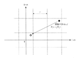
THPを用いた通信で、送受信の両側で行われるModulo演算について説明する。このModulo演算は送信信号を一定振幅以下に保つことによって送信電力を低減する処理である。具体的にいうと、Modulo演算は、送信信号のI-ch(In-phase channel), Q-ch(Qudrature channel)に対して送受信両側で既知の値τの整数倍の信号を加算することにより、当該信号が[-τ /2, τ /2]の範囲に収まる信号になるように変換する演算である。このModulo演算の一例を図24に示した。図24中ではModulo演算は、●で表される信号が○の位置に移動する処理で表され、●に摂動ベクトルd( =(-2) τ +j *(-1) τ)を加算することで○に移動している。jは虚数単位である。○はI-ch,Q-chともに原点から[-τ /2, τ /2]の範囲に収まっている。このようにModulo演算は信号の振幅を一定範囲内に収める効果を持つ。通常、Modulo幅τは、変調シンボルの平均電力を1に正規化した場合、変調方式に応じて、あらかじめ送受信側で既知な所定の値となる。例えば、QPSKではτ=2√2、16QAMでは、τ=8/√10、64QAMではτ=16/√42である。 A Modulo operation performed on both sides of transmission and reception in communication using THP will be described. This Modulo operation is a process for reducing the transmission power by keeping the transmission signal below a certain amplitude. Specifically, the Modulo operation is performed by adding a signal that is an integral multiple of a known value τ on both sides of transmission and reception to the I-ch (In-phase channel) and Q-ch (Qudrature channel) of the transmission signal. This is an operation for converting the signal so that the signal falls within the range of [−τ / 2, τ / 2]. An example of this Modulo calculation is shown in FIG. In FIG. 24, the Modulo operation is represented by a process in which the signal represented by ● moves to the position of ○, and the perturbation vector d (= (− 2) τ + j * (− 1) τ) is added to ●. I moved to ○. j is an imaginary unit. ○ is within the range of [-τ / 2, τ / 2] from the origin for both I-ch and Q-ch. Thus, the Modulo operation has the effect of keeping the signal amplitude within a certain range. Normally, when the average power of the modulation symbol is normalized to 1, the Modulo width τ is a predetermined value known in advance on the transmission / reception side according to the modulation scheme. For example, τ = 2√2 for QPSK, τ = 8 / √10 for 16QAM, and τ = 16 / √42 for 64QAM.
このModulo演算により、受信側が大きな干渉を受ける環境にあっても、干渉除去による送信電力の増加を抑えながら、信号を送信することができる。またModulo演算を式で示すと、
次に、THPの原理を説明する。所望信号をsとし、干渉をfとする。送信装置は、まず干渉fを所望信号sから減算する。THPは干渉fをあらかじめ把握しているのが前提だからである。しかし、減算した信号s - f は通常振幅が大きいため、このまま送信すると送信電力が増加してしまう。そこで、送信装置は、この信号s - f に対してModulo演算を行って、Modt(s - f )で示される信号を送信する。 Next, the principle of THP will be described. Let s be the desired signal and f be the interference. The transmitting apparatus first subtracts the interference f from the desired signal s. This is because THP assumes that the interference f is known in advance. However, since the subtracted signal s-f usually has a large amplitude, if it is transmitted as it is, the transmission power increases. Therefore, the transmission device performs a Modulo operation on the signal s − f and transmits a signal indicated by Mod t (s − f).
すると、送信装置は、送信信号をI-ch Q-chともに原点から[-τ /2, τ /2]の範囲に収めることができており、信号s - f を送るときに比べて、電力を抑圧した信号を送信できる。ここで、伝搬路の特性を1とし、雑音の影響を無視すると、受信信号はModt(s - f )+ f となる。受信装置は干渉fを受けるからである。受信装置が、この受信信号に対してModulo演算を行うと、
2.MU-MIMO THP
(全体のシステム構成)
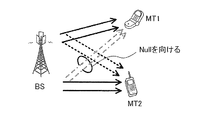
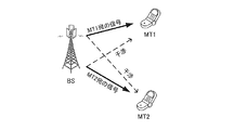
図25に示すように、基地局(Base Station: BS)が同一時刻・同一周波数で複数の端末(Mobile Terminal: MT)に対して信号を送信すると、通常は、ユーザ間干渉(Multi User Interference: MUI)が発生する。THPを用いてこのMUIを電力効率良く除去して、複数のMTを多重する方法が、ダウンリンク(Downlink: DL)のMU-MIMO(Multi-User Multi Input Multi Output)である。
2. MU-MIMO THP
(Overall system configuration)
As shown in FIG. 25, when a base station (Base Station: BS) transmits a signal to a plurality of terminals (Mobile Terminal: MT) at the same time and the same frequency, normally, multi-user interference (Multi User Interference: MUI) occurs. A method of removing the MUI efficiently using THP and multiplexing a plurality of MTs is a downlink (DL) MU-MIMO (Multi-User Multi Input Multi Output).
DL MU-MIMO THPは、BSがMTの伝搬路状態情報(Channel State Information: CSI)を全て把握していることが前提の技術である。なぜなら、上述の通りTHPは、送信装置であるBSが、受信装置であるMTの受ける干渉を把握していることが必要であり、DL MU-MIMO THPでは、その干渉を算出するために、CSIを用いる必要があるからである。 DL MU-MIMO THP is a technology based on the premise that the BS knows all MT channel state information (Channel State Information: CSI). This is because, as described above, the THP requires that the BS that is the transmission device knows the interference that the MT that is the reception device receives, and the DL MU-MIMO THP uses CSI to calculate the interference. This is because it is necessary to use.
以降、図を参照しながら、このDL MU-MIMIO THPのBSとMTの構成を説明する。今回は簡潔に説明するためにMTが2人の場合について述べるが、任意の数のMTをMU-MIMO THPで多重する場合も同様に実現できる。(下記非特許文献2参照)
Hereinafter, the BS and MT configurations of this DL MU-MIMIO THP will be described with reference to the drawings. For the sake of concise explanation, the case where there are two MTs will be described here, but the same can be realized when any number of MTs are multiplexed by MU-MIMO THP. (See Non-Patent
(BS構成図(2MTs))
BSは、各MT宛のCSIを把握しており、同時に2つのMTに同一時刻・同一周波数で信号を送信する。このとき、図25に示したように、2つのMT(MT1、MT2)が互いに干渉を受けないようにするために、MT1宛の信号がMT2に及ぼす干渉と、MT2宛の信号がMT1に及ぼす干渉という相互に及ぼし合う2つの干渉を除去する必要がある。BSは、この2つの干渉のうち一方を、THPを用いて除去し、もう一方を、線形フィルタを乗算して除去する。2つのMTとの通信を実現するための具体的なBSの一構成例を図26に示す。以下、図26に示す構成例に従ってBSの構成について説明する。
(BS configuration diagram (2MTs))
The BS knows the CSI addressed to each MT, and simultaneously transmits signals to the two MTs at the same time and the same frequency. At this time, as shown in FIG. 25, in order to prevent the two MTs (MT1, MT2) from receiving interference with each other, the interference of the signal addressed to MT1 on MT2 and the signal addressed to MT2 affect MT1. It is necessary to remove two interferences that interfere with each other. The BS removes one of the two interferences using THP and removes the other by multiplying by a linear filter. FIG. 26 shows a configuration example of a specific BS for realizing communication with two MTs. The configuration of the BS will be described below according to the configuration example shown in FIG.
(BSの構成)
まず、符号部101−1、2は、各MT宛の情報ビットを誤り訂正符号化し、各MT宛の符号化ビットを変調部103−1、2に入力する。変調部103−1、2は、入力された各MT宛の符号化ビットを変調し、各MT宛の変調信号を生成する。MT1宛の変調信号を生成した変調部103−1は、干渉算出部113と線形フィルタ乗算部115にMT1宛の変調シンボルを入力する。MT2宛の変調信号を生成した変調部103−2は、干渉減算部107にMT2宛の変調シンボルを入力する。
(Structure of BS)
First, the encoding units 101-1 and 101-2 perform error correction encoding on information bits addressed to each MT, and input the encoded bits addressed to each MT to the modulation units 103-1 and 103-2. Modulation sections 103-1 and 103-2 modulate the input coded bits addressed to each MT to generate modulated signals addressed to each MT. Modulation section 103-1 that has generated the modulation signal addressed to MT1 inputs the modulation symbol addressed to MT1 to
線形フィルタ算出部117は、BSが把握しているCSIを用いて線形フィルタと干渉係数情報を算出し、それぞれ線形フィルタ乗算部115と干渉算出部113に入力する。次に、干渉算出部113は、MT1宛の変調信号を生成した変調部103−1から入力された変調信号と干渉係数情報とを用いてMT2が受ける干渉を算出し、干渉減算部107に入力する。干渉減算部107は、MT2宛の変調信号から、MT2が受ける干渉を減算した後、その減算後の信号をModulo演算部111に入力する。Modulo演算部111は、減算後の信号に対して式(1)で示したModulo演算を施し、Modulo演算後の信号を線形フィルタ乗算部115に入力する。図26において、破線で囲んだ干渉減算部107、干渉算出部113、及びModulo演算部111を非線形空間多重部105と呼ぶ。
The linear
線形フィルタ乗算部115は、入力されたMT1宛の信号と、MT2宛の信号に対して線形フィルタを乗算する。これにより、MT2宛の信号のNullが、MT1の方向に向き、MT2宛信号がMT1に干渉を及ぼさないようになる。
The
その後、線形フィルタ乗算部115は、線形フィルタ乗算後の信号を送信部121−1、2に入力する。送信部121−1、2は、線形フィルタ乗算後の信号をデジタル/アナログ変換した後に、搬送波周波数にアップコンバージョンしてMT1及びMT2宛に信号を送信する。
Thereafter, the linear
(MT構成図(2MTs))
MT1, MT2は、BSから送信された信号を受信する。各MTは受信信号に対してBSと同じModulo演算を用いて受信処理を行う。図27を参照してMTの詳細な説明を行う。
(MT configuration diagram (2MTs))
MT1 and MT2 receive signals transmitted from the BS. Each MT performs reception processing on the received signal using the same Modulo operation as BS. The MT will be described in detail with reference to FIG.
(MTの構成)
受信部131は、アンテナATで受信した信号を搬送波周波数からベースバンドにダウンコンバージョンし、アナログ/デジタル変換を行い、ベースバンドデジタル信号を生成する。その後、受信部131は、ベースバンドデジタル信号を伝搬路補償部133に入力する。伝搬路補償部133は、ベースバンドデジタル信号に対して伝搬路補償を行って、伝搬路補償後の信号をModulo演算部135に入力する。Modulo演算部135は、伝搬路補償後の信号に対して式(1)で表されるModulo演算を施して復調部に信号を入力する。復調部137は、Modulo後の信号に対して復調を行って復調結果を復号部141に入力する。
(Configuration of MT)
The receiving
(理論説明)
図26及び図27を参照しながら説明したように、DL MU-MIMO THPの仕組みは、MT1宛の信号とMT2宛の信号が相互に及ぼし合う干渉のうち一方を、THPによって除去し、もう一方を線形フィルタの乗算によって除去することである。次は、このDL MU-MIMO THPの仕組みを理論的な側面から詳細に説明する。
(Theory explanation)
As described with reference to FIG. 26 and FIG. 27, the DL MU-MIMO THP mechanism removes one of the interferences between the signals addressed to MT1 and the signal addressed to MT2 by THP, Is removed by multiplication of a linear filter. Next, the mechanism of this DL MU-MIMO THP will be explained in detail from the theoretical side.
(変数定義)
いま、BSの持つ2本のアンテナからMT1への伝搬路の複素利得を、h11, h21とする。また同様にMT2への伝搬路の複素利得をh21, h22とする。これらの値を用いて伝搬路行列Hを、
Now, let the complex gain of the propagation path from the two antennas of the BS to MT1 be h 11 and h 21 . Similarly, let the complex gain of the propagation path to MT2 be h 21 and h 22 . Using these values, the propagation path matrix H
(線形フィルタの計算)
線形フィルタ乗算部115は、線形フィルタを用いてMT2宛の信号をMT1に対してNullを向けることで、MT2宛の信号がMT1に及ぼす干渉を除去する。この線形フィルタは、線形フィルタ乗算部115が、伝搬路行列Hのエルミート共役HHをQR分解することによって求められる。QR分解は任意の行列をユニタリ行列Qと上三角行列Rの積に分解する方法であり、HHをQR分解すると、
The
(干渉の算出)
線形フィルタにより、MT2宛の信号がMT1に及ぼす干渉を除去できたので、次はMT1宛の信号がMT2に及ぼす干渉を上述のTHPを用いて除去する。
(Calculation of interference)
The interference that the signal addressed to MT2 exerts on MT1 can be removed by the linear filter. Next, the interference that the signal addressed to MT1 affects MT2 is removed using the above-described THP.
式(2)にあるように、BSがTHPを行うためにはまず、干渉fを計算しなければならない。ここでは、MT2が伝搬路補償をした後の干渉をfとして、この値を求める。式(6)より、MT2が伝搬路補償をした後の受信信号をz2すると、
(THP)
BSは、干渉fとMT2宛の変調信号s2を用いて、干渉減算部107及びModulo演算部111で信号Modt(s2 - f )を算出し、この信号を線形フィルタ乗算部115に入力する。線形フィルタ乗算部115は、信号Modt(s2 - f )とMT1宛の信号s1に対して線形フィルタQを乗算して送信信号を算出する。ここで、図26に示した干渉減算部107、干渉算出部113、及びModulo演算部111を非線形空間多重部105と呼び、変調信号から干渉除去及びModulo演算を施して線形フィルタ乗算部115に入力する信号を計算する処理を非線形空間多重と呼ぶ。
(THP)
BS calculates signal Mod t (s 2 −f) by
(受信信号)
式(6)のs2をModt(s2 - f )に替えて受信信号を求めると、
When the received signal is obtained by changing s 2 in Equation (6) to Mod t (s 2 -f),
このようにMT1とMT2の両方で自分宛の信号を検出することができる。 In this way, the signal addressed to itself can be detected by both MT1 and MT2.
3.複数の受信アンテナを持つMTに対するマルチストリーム通信
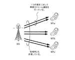
上記で説明したのは、データストリームを1つずつ別のMTに送信する方法であるが、図28に示すように、複数の受信アンテナを持ち、SU-MIMOによる複数のデータストリーム通信を行うMT同士を、さらに同一時刻・同一周波数でMU-MIMO THPによって空間多重する技術も存在する(非特許文献3参照)。この技術により、複数受信アンテナを持つMTに対しても空間リソースを有効活用することができる。このように、複数ストリーム通信を行っている時も、BSは各MT宛の各データストリームにModulo演算を施して送信している。
3. Multi-stream communication for MTs having a plurality of receiving antennas The method described above is a method of transmitting a data stream to another MT one by one. However, as shown in FIG. There is also a technique of spatially multiplexing MTs that perform a plurality of data stream communications by MIMO using MU-MIMO THP at the same time and the same frequency (see Non-Patent Document 3). With this technology, spatial resources can be effectively utilized even for MTs having multiple receiving antennas. Thus, even when performing multi-stream communication, the BS performs a Modulo operation on each data stream addressed to each MT and transmits the data stream.
4. DRSについて
DL MU-MIMO THPでは、復調用の各MT宛の固有参照信号 (Dedicated Reference Signals: DRS) を送信するときに、直交した無線リソースに各MT宛のDRSを分割する多重方法(時間分割多重や周波数分割多重やなど)を用いており、空間多重は用いられていない(特許文献1参照)。以下、直交した無線リソースに分割して配置する各MT宛のDRSを「直交DRS」と呼ぶ。直交DRSを用いるのは、もし、BSが、情報ビットを変調した信号等で構成されるデータ信号と同様にDRSをMU-MIMO THPによる空間多重をして送信すると、MTは信号の振幅がわからないためDRSに対してModulo演算ができず、Modulo演算を施されて送信されたDRSに基づいて伝搬路推定ができないからである。
4). About DRS
In DL MU-MIMO THP, when transmitting dedicated reference signals (DRS) destined for each MT for demodulation, a multiplexing method that divides the DRS destined for each MT into orthogonal radio resources (such as time division multiplexing or Frequency division multiplexing or the like) is used, and spatial multiplexing is not used (see Patent Document 1). Hereinafter, a DRS addressed to each MT that is divided into orthogonal radio resources is referred to as an “orthogonal DRS”. The orthogonal DRS is used if the BS does not know the amplitude of the signal if the BS transmits DRS by spatial multiplexing using MU-MIMO THP as well as the data signal composed of information bit modulated signal etc. Therefore, the Modulo operation cannot be performed on the DRS, and the propagation path cannot be estimated based on the DRS transmitted after the Modulo operation.
直交した無線リソースで各MTにDRSを送信する場合、BSは、あらかじめBSとMTの両方で既知のDRS (信号点平面上において複素数qで表されるとする。) を送信する。このとき、BSは、一つの直交した無線リソースで一つのMTに対してのみDRSを送信し、他のMTに対しては信号を送信しない。そのため、MTは、干渉の影響を受けずに、BSが送信したDRSを受信でき、DRSの受信信号点yをqで除算することで、伝搬路h = y/q と求めることができる。 When transmitting a DRS to each MT using orthogonal radio resources, the BS transmits a known DRS (represented by a complex number q on the signal point plane) in both the BS and the MT in advance. At this time, the BS transmits a DRS only to one MT with one orthogonal radio resource, and does not transmit a signal to other MTs. Therefore, the MT can receive the DRS transmitted by the BS without being affected by the interference, and can determine the propagation path h = y / q by dividing the received signal point y of the DRS by q.
一方、BSが、データ信号と同様にTHPによる空間多重をして、DRSを同時に複数MTに対して送信しても、MTは、伝搬路推定することができない。なぜなら、BSは、DRSに対してModulo演算を施してから送信するので、MTは基準となる信号がqではなく、信号qに対してModulo演算によって摂動ベクトルdが加算されているからである。つまり基準となる信号は、q+dであらわされる点であり、MTは、DRSの受信信号点yをq+dで除算すべきところ、dの値をあらかじめ知ることはできないので、 伝搬路hの値を推定できない。 On the other hand, even if the BS performs spatial multiplexing by THP in the same manner as the data signal and simultaneously transmits DRS to a plurality of MTs, the MT cannot estimate the propagation path. This is because the BS performs Modulo operation on the DRS and then transmits the signal, so that the reference signal is not q but the perturbation vector d is added to the signal q by Modulo operation. In other words, the reference signal is the point represented by q + d, and MT should divide the DRS received signal point y by q + d, but cannot know the value of d in advance. Cannot be estimated.
そのため、DL MU-MIMO THPは各MT宛のDRSを空間多重する方法を用いず、直交DRSを用いている (下記特許文献1参照)。
Therefore, DL MU-MIMO THP does not use a method of spatially multiplexing DRSs addressed to each MT, but uses orthogonal DRSs (see
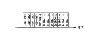
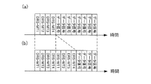
直交DRSを空間多重するMT数分だけ時間分割多重して、残りのシンボルで空間多重したデータ信号を送信する。例えば、図29(a)のDRS−MT1,DRS−MT2,…,DRS−MT4のように直交DRSを時間多重する必要がある。 Data signals that are time-division-multiplexed by the number of MTs for which orthogonal DRS is spatially multiplexed are spatially multiplexed with the remaining symbols. For example, orthogonal DRSs need to be time-multiplexed like DRS-MT1, DRS-MT2,..., DRS-MT4 in FIG.
一方で、データ信号を正確に復調又は復号するためには伝搬路推定精度を向上させる必要がある。そのため、BSが各MTに対して複数回DRSを送信し、MTがその複数のDRSを合成することが理想的である。 On the other hand, in order to accurately demodulate or decode a data signal, it is necessary to improve propagation path estimation accuracy. Therefore, it is ideal that the BS transmits the DRS multiple times to each MT, and the MT combines the plurality of DRSs.
しかしながら、複数回にわたって直交DRSを送信すると、制御情報のオーバーヘッドが増加してしまう。例えば、図29(b)のように直交DRSの送信のために消費するシンボルの数が増加し、送信データレートが大きく低下してしまう。もちろん、図29(a)と図29(b)との構成は、一例であって、この問題は、DL MU-MIMO THPによる空間多重を用いた通信システム一般に言えることである。 However, if orthogonal DRSs are transmitted multiple times, the overhead of control information increases. For example, as shown in FIG. 29B, the number of symbols consumed for orthogonal DRS transmission increases, and the transmission data rate greatly decreases. Of course, the configurations shown in FIGS. 29 (a) and 29 (b) are merely examples, and this problem is generally applicable to communication systems using spatial multiplexing based on DL MU-MIMO THP.
そこで、本発明は、MU-MIMO THPによる空間多重を用いた通信システムにおいて、送信データレートの低下を最小限に抑えながら、伝搬路推定精度を向上する方法を提供することを目的とする。 Therefore, an object of the present invention is to provide a method for improving propagation path estimation accuracy while minimizing a decrease in transmission data rate in a communication system using spatial multiplexing by MU-MIMO THP.
特開2009-182894号公報に記載されている時間多重等を行う復調用パイロットに加えて、データと同じDL MU-MIMO THPの原理により空間多重した復調用パイロットを送信する。各MTは直交した無線リソースで送信された復調用パイロットと空間多重されたパイロットを組み合わせることで二つのパイロットを所定の方法により合成して伝搬路推定する。 In addition to the demodulation pilot that performs time multiplexing described in JP-A-2009-182894, a demodulation pilot that is spatially multiplexed according to the same DL MU-MIMO THP principle as data is transmitted. Each MT combines two pilots by a predetermined method by combining a demodulating pilot transmitted with orthogonal radio resources and a spatially multiplexed pilot, and estimates a propagation path.
本発明の一観点によれば、複数の受信装置に対して、同一チャネル・同一時刻に信号を送信する、複数の送信アンテナを備えた送信装置であって、前記各受信装置宛のDRS(固有参照信号)を生成するDRS生成部と、前記DRSの少なくとも一部からなる第1のグループのDRSを用いて非直交DRSを生成する非線形空間多重部と、少なくとも前記非直交DRSを含んだ信号を送信する送信部と、を有することを特徴とする送信装置が提供される。さらに、前記DRSの少なくとも一部からなる第2のグループのDRSを用いて直交DRSを生成する直交多重部を有し、前記送信部は、前記非直交DRSと前記直交DRSを少なくとも1つずつ含んだ信号を送信することを特徴とする。 According to one aspect of the present invention, there is provided a transmission device including a plurality of transmission antennas that transmit signals to a plurality of reception devices at the same channel and at the same time, and that is a DRS (unique to each reception device). A DRS generator that generates a reference signal), a nonlinear spatial multiplexing unit that generates a non-orthogonal DRS using a DRS of a first group that includes at least a part of the DRS, and a signal including at least the non-orthogonal DRS There is provided a transmission device including a transmission unit for transmission. And an orthogonal multiplexing unit that generates an orthogonal DRS using a DRS of a second group including at least a part of the DRS, and the transmission unit includes at least one of the non-orthogonal DRS and the orthogonal DRS. It is characterized by transmitting a signal.
さらに、前記各受信装置宛のデータ信号を生成するデータ信号生成部を有し、前記非線形空間多重部は、前記データ信号に対して非線形空間多重を施し、前記送信部は、さらに前記非線形空間多重したデータ信号を前記複数の受信装置に送信することが好ましい。 And a data signal generation unit that generates a data signal addressed to each receiving device, wherein the nonlinear spatial multiplexing unit performs nonlinear spatial multiplexing on the data signal, and the transmission unit further includes the nonlinear spatial multiplexing. The transmitted data signal is preferably transmitted to the plurality of receiving devices.
さらに、伝搬路状態情報に基づいて線形フィルタと干渉係数情報とを算出する線形フィルタ算出部を有し、前記非線形空間多重部は、前記データ信号又は前記第1のグループの一部のDRSに基づいて前記各受信装置が受ける干渉を算出する干渉算出部と、前記各受信装置に対する、前記各データ信号又は前記第1のグループのDRSから、前記干渉を減算する干渉減算部と、前記干渉減算部で前記干渉を減算した少なくとも1つの前記データ信号又は前記干渉を減算した前記第1のグループに属する少なくとも1つのDRSに対してModulo演算を施すModulo演算部と、を有することを特徴とする。 And a linear filter calculating unit that calculates a linear filter and interference coefficient information based on propagation path state information, wherein the nonlinear spatial multiplexing unit is based on the DRS of the data signal or part of the first group. An interference calculating unit that calculates interference received by each receiving device, an interference subtracting unit that subtracts the interference from each data signal or DRS of the first group for each receiving device, and the interference subtracting unit A Modulo operation unit that performs a Modulo operation on at least one data signal obtained by subtracting the interference or at least one DRS belonging to the first group obtained by subtracting the interference.
複数の受信装置宛のDRSが空間多重されている非直交DRSを受信する受信部と、少なくとも前記非直交DRSに基づいて伝搬路推定を行う伝搬路推定部と、を有することを特徴とする受信装置であっても良い。 A reception unit comprising: a reception unit that receives a non-orthogonal DRS in which DRSs addressed to a plurality of reception devices are spatially multiplexed; and a propagation path estimation unit that performs propagation path estimation based on at least the non-orthogonal DRS It may be a device.
さらに、前記受信部は、直交DRSを受信し、前記伝搬路推定部は、少なくとも前記直交DRSと前記非直交DRSとに基づいて伝搬路推定を行う伝搬路推定部と、を有することが好ましい。前記伝搬路推定部は、前記直交DRSに基づいて第一の伝搬路推定を行う直交DRS推定部と、前記第一の伝搬路推定結果と前記非直交DRSとに基づいて、当該非直交DRSに加算された摂動ベクトルを推定する摂動ベクトル推定部とを有することが好ましい。前記伝搬路推定部は、前記非直交DRS、前記摂動ベクトル、及び、前記直交DRSに基づいて伝搬路推定値を算出する合成DRS推定部と、を有することが好ましい。 Furthermore, it is preferable that the reception unit receives an orthogonal DRS, and the propagation path estimation unit includes a propagation path estimation unit that performs propagation path estimation based on at least the orthogonal DRS and the non-orthogonal DRS. The propagation path estimator is configured to perform an orthogonal DRS estimation unit that performs a first propagation path estimation based on the orthogonal DRS, and to the non-orthogonal DRS based on the first propagation path estimation result and the non-orthogonal DRS. It is preferable to have a perturbation vector estimation unit that estimates the added perturbation vector. The propagation path estimation unit preferably includes a combined DRS estimation unit that calculates a propagation path estimation value based on the non-orthogonal DRS, the perturbation vector, and the orthogonal DRS.
前記受信部は、直交DRS及び複数の非直交DRSを受信し、前記伝搬路推定部は、直交DRSに基づいて伝搬路推定値を算出する直交DRS推定部と、前記伝搬路推定値と複数の前記非直交DRSの一部に基づいて、当該非直交DRSに加算された摂動べクトルをそれぞれ推定する摂動ベクトル推定部と、前記一部の非直交DRS、前記摂動ベクトル、及び、前記直交DRSに基づいて伝搬路推定値を算出する合成DRS推定部と、を有することが好ましい。 The reception unit receives an orthogonal DRS and a plurality of non-orthogonal DRSs, the propagation path estimation unit calculates an propagation path estimation value based on the orthogonal DRS, the propagation path estimation value and a plurality of propagation path estimation values Based on a part of the non-orthogonal DRS, a perturbation vector estimator for estimating the perturbation vector added to the non-orthogonal DRS, the part of the non-orthogonal DRS, the perturbation vector, and the orthogonal DRS And a combined DRS estimator that calculates a propagation path estimated value based on the estimated value.
前記摂動ベクトル推定部は、前記一部の非直交DRS以外の非直交DRSと、前記伝搬路推定値と、に基づいて、当該前記一部の非直交DRS以外の非直交DRSに加算された摂動べクトルをそれぞれ推定することが好ましい。 The perturbation vector estimator is a perturbation added to a non-orthogonal DRS other than the part of the non-orthogonal DRS based on the non-orthogonal DRS other than the part of the non-orthogonal DRS and the propagation path estimation value. It is preferable to estimate each vector.
また、複数の受信装置と、前記複数の受信装置に対して、同一チャネル・同一時刻に複数の送信アンテナを用いて信号を送信する送信装置からなる通信システムであって、前記送信装置は、前記各受信装置宛のDRS(固有参照信号)を生成するDRS生成部と、前記DRSの少なくとも一部からなる第1のグループのDRSを用いて非直交DRSを生成する非線形空間多重部と、少なくとも前記非直交DRSを含んだ信号を送信する送信部と、を有し、前記受信装置は、複数の受信装置宛のDRSが空間多重されている非直交DRSを受信する受信部と、少なくとも前記非直交DRSに基づいて伝搬路推定を行う伝搬路推定部と、を有することを特徴とする通信システムであっても良い。 In addition, the communication system includes a plurality of reception devices and a transmission device that transmits signals to the plurality of reception devices using a plurality of transmission antennas on the same channel and at the same time. A DRS generator for generating a DRS (unique reference signal) addressed to each receiving device; a non-orthogonal DRS that generates a non-orthogonal DRS using a first group of DRSs comprising at least a part of the DRS; A transmitter that transmits a signal including a non-orthogonal DRS, and the receiver includes a receiver that receives a non-orthogonal DRS in which DRSs for a plurality of receivers are spatially multiplexed, and at least the non-orthogonal A communication system characterized by having a propagation path estimation unit that performs propagation path estimation based on DRS.
また、複数の受信装置に対して、同一チャネル・同一時刻に複数の送信アンテナを用いて信号を送信する方法であって、前記各受信装置宛のDRS(固有参照信号)を生成するステップと、前記DRSの少なくとも一部からなる第1のグループのDRSを用いて非直交DRSを生成するステップと、少なくとも前記非直交DRSを含んだ信号を送信するステップと、を有する送信方法が提供される。 Further, for a plurality of receiving devices, a method of transmitting signals using a plurality of transmitting antennas at the same channel and the same time, the step of generating a DRS (specific reference signal) addressed to each receiving device; There is provided a transmission method comprising: generating a non-orthogonal DRS using a first group of DRSs composed of at least a part of the DRS; and transmitting a signal including at least the non-orthogonal DRS.
直交DRS及び非直交DRSを受信するステップと、直交DRSに基づいて伝搬路推定値を算出するステップと、前記伝搬路推定値と非直交DRSに基づいて伝搬路推定するステップと、を有することを特徴とする受信方法であっても良い。 Receiving orthogonal DRS and non-orthogonal DRS; calculating a channel estimation value based on the orthogonal DRS; and estimating a channel based on the channel estimation value and the non-orthogonal DRS. A characteristic reception method may be used.
本発明は、上記に記載の方法をコンピュータに実行させるためのプログラムであっても良く、該プログラムを記録する記録媒体でも良い。プログラムは、インターネットなどの伝送媒体によって取得されても良い。 The present invention may be a program for causing a computer to execute the method described above, or a recording medium for recording the program. The program may be acquired by a transmission medium such as the Internet.
また、複数の受信装置に対して、同一チャネル・同一時刻に信号を送信する、複数の送信アンテナを備えた送信装置で使用されるプロセッサであって、前記各受信装置宛のDRS(固有参照信号)を生成するDRS生成部と、前記DRSの少なくとも1からなる第1のグループのDRSを用いて非直交DRSを生成する非線形空間多重部と、少なくとも前記非直交DRSを含んだ信号を送信する送信部と、を有することを特徴とするプロセッサであっても良い。 A processor used in a transmission apparatus having a plurality of transmission antennas that transmits signals to a plurality of reception apparatuses at the same channel and at the same time, and that is a DRS (unique reference signal) addressed to each of the reception apparatuses. ) Generating a non-orthogonal DRS using a first group of DRSs composed of at least one of the DRSs, and transmitting a signal including at least the non-orthogonal DRSs And a processor characterized by having a unit.
また、受信装置に用いられるプロセッサであって、複数の受信装置宛のDRSが空間多重されている非直交DRSを受信する受信部と、少なくとも前記非直交DRSに基づいて伝搬路推定を行う伝搬路推定部と、を有することを特徴とするプロセッサでも良い。 Also, a processor used in the receiving device, a receiving unit that receives a non-orthogonal DRS in which DRSs addressed to a plurality of receiving devices are spatially multiplexed, and a propagation channel that performs channel estimation based on at least the non-orthogonal DRS And a processor characterized by having an estimation unit.
空間多重された非直交DRSは、一つの無線リソースで全MTに対してパイロットを送信できるので、データ信号を配置するための無線リソースを十分確保することができる。加えて、非直交DRSと直交DRSとを送信することで、伝搬路推定精度も向上することができる。 Since the spatially multiplexed non-orthogonal DRS can transmit pilots to all MTs with one radio resource, it is possible to sufficiently secure radio resources for arranging data signals. In addition, transmission accuracy can be improved by transmitting non-orthogonal DRS and orthogonal DRS.
以下、本発明の実施の形態による移動体通信技術について説明する。
<第1の実施の形態>
本発明の第1の実施の形態は、基地局(BS)が各移動局MTに対して直交DRSを送信するとともに、各MT宛のDRSを、データ信号と同様の方法で非線形空間多重して送信する。このDRSを、「非直交DRS」と呼ぶ。MTは直交DRSと非直交DRSの両方を用いて伝搬路推定する。以下、図を参照しながら本実施例の詳細な構成について説明する。
Hereinafter, a mobile communication technique according to an embodiment of the present invention will be described.
<First Embodiment>
In the first embodiment of the present invention, the base station (BS) transmits orthogonal DRS to each mobile station MT, and DRS addressed to each MT is subjected to nonlinear spatial multiplexing in the same manner as the data signal. Send. This DRS is referred to as “non-orthogonal DRS”. MT estimates the channel using both orthogonal DRS and non-orthogonal DRS. The detailed configuration of the present embodiment will be described below with reference to the drawings.
1)BSの構成
図1は、本実施の形態におけるBSの一構成例を示す機能ブロック図である。図26に示す従来例では、簡潔に説明するためにMT数とBSのアンテナ数とが2つの場合について説明したが、図1に示す構成例では、MT数が任意のN個存在する場合について説明する。
1) Configuration of BS FIG. 1 is a functional block diagram showing a configuration example of a BS in the present embodiment. In the conventional example shown in FIG. 26, the case where the number of MTs and the number of BS antennas is two has been described for the sake of brevity. However, in the configuration example shown in FIG. explain.
図1に示すように、BS(A)は、まずアンテナAT−1〜N毎に共通参照信号 (Common Reference Signals: CRS) を、CRS生成部27で生成して、送信部25−1〜NにCRSを入力する。送信部25−1〜Nは、入力されたCRSに対してデジタル/アナログ変換後を行い、アップコンバージョンし、搬送波周波数の無線信号を生成して、アンテナAT−1〜Nを介してMTにCRSを送信する。その後、MTがCRSに基づいてBSの各アンテナからの伝搬路状態を推定し、伝搬路状態情報を含む無線信号 (伝搬路状態信号) をBS(A)に送信する。
As shown in FIG. 1, the BS (A) first generates common reference signals (CRS) for each of the antennas AT-1 to AT-N by the
BSの受信部29−1〜Nは、アンテナAT−1〜Nを介して伝搬路状態信号を受信し、伝搬路状態信号をダウンコンバージョンしてベースバンドデジタル信号を生成後、伝搬路状態情報取得部31に当該ベースバンドデジタル信号を入力する。このベースバンドデジタル信号は、MTがBSに対して通知する伝搬路状態情報を含む信号である。伝搬路状態情報取得部31は、当該ベースバンドデジタル信号から伝搬路状態情報を取得し、線形フィルタ算出部23に入力する。線形フィルタ算出部33は、伝搬路状態情報から従来例に示した方法と同様の方法で線形フィルタと干渉係数情報とを算出し、線形フィルタを線形フィルタ乗算部33に、干渉係数情報を非線形空間多重部11に入力する。またMT数がN個の場合に一般化したときの、この線形フィルタ算出部33の動作を後に詳細に記述している。
BS receiving units 29-1 to 29-N receive propagation path state signals via antennas AT-1 to N, down-convert the propagation path state signals to generate baseband digital signals, and then obtain propagation path state information. The baseband digital signal is input to the
DRS生成部15は、各MTに対するDRSを生成し、非線形空間多重部11に入力する。ここでDRS生成部15が非線形空間多重部11に入力するDRSを第1のグループのDRSという。さらに、DRS生成部15は、各MTに対するDRSをもう一度生成し、直交多重部17に入力する。ここでDRS生成部15が直交多重部17に入力するDRSを第2のグループのDRSという。非線形空間多重部11は、入力された各MTに対するDRSに対して非線形空間多重を施し、非直交DRSを生成して固有信号構成部21に入力する。非線形空間多重部11の動作は、従来例の図26に示したものと同様である。但し、従来例においてはデータ信号に対して非線形空間多重をしているが、本実施の形態では、データ信号に加えてDRSにも非線形空間多重を施す。また、MT数を一般的にN個とした時の非線形空間多重部の詳細な動作を後述する。
The
また、直交多重部17は、入力されたDRSを、互いに直交する無線リソースに配置して多重し、直交DRSを生成して、固有信号構成部21に入力する。ここで、直交する無線リソースへの配置とは、MT数が4のときを例にとると、図2に示すように、時間分割多重 (Time Division Multiplexing: TDM) でもよいし、符号分割多重(Code Division Multiplexing: CDM) などを用いても良い。図2は、各MT宛の直交DRSをDRS-MT1, DRS-MT2などと示した。また後述するように直交周波数分割多重 (Orthogonal Frequency Division Multiplexing: OFDM) などを用いたマルチキャリア通信をする場合は、TDMとCDMに加えてFDMを組み合わせた多重をしてもよい。以下、一例としてTDMで直交DRSを多重する場合について説明していく。
Further, the
符号化部5−1〜Nは、各MT宛の情報ビットに誤り訂正符号化を施して符号化後のビットを変調部7−1〜Nに入力する。変調部7−1〜Nは、入力されたビットを変調して、変調信号を生成し、非線形空間多重部11に入力する。ここで、符号部5−1〜Nと変調部7−1〜Nを合わせた構成部分をデータ信号生成部3と呼ぶ。当該変調信号をデータ信号と呼ぶこととする。非線形空間多重部11は入力された各MTに対するデータ信号に対して非直交DRSと同様の非線形空間多重を施し、非線形空間多重が施されたデータ信号を生成して固有信号構成部21に入力する。
Encoding sections 5-1 to N perform error correction encoding on information bits addressed to each MT, and input the encoded bits to modulation sections 7-1 to N. The modulation units 7-1 to N modulate the input bits to generate a modulated signal and input the modulated signal to the nonlinear
固有信号構成部21は、データ信号、非直交DRS、及び直交DRSを用いて固有信号を構成する。このときのフレーム構成を例としてMT数が4のときの信号を図3に示した。非直交DRSは、データ信号と同様に、各MT宛の信号を多重しているので、1シンボル分の時間で全MTに信号を送信することができる。
The unique
固有信号構成部21は、このようにして構成した固有信号を線形フィルタ乗算部23に入力する。線形フィルタ乗算部23は、入力された固有信号に線形フィルタを乗算し、各アンテナに対応する信号を生成して送信部25−1〜Nに入力する。
送信部25−1〜Nは、入力された各アンテナに対応する信号に対してデジタル/アナログ変換を行い、アップコンバージョンし、搬送波周波数の無線信号を生成して、アンテナを介してMTに各MT宛の信号を送信する。
The
The transmitters 25-1 to 25 -N perform digital / analog conversion on the signals corresponding to the input antennas, up-convert, generate radio signals of carrier frequency, and transmit the MTs to the MTs via the antennas. Send the addressed signal.
2)MTの構成
本実施の形態におけるMTの構成例について、図4A、図4Bを用いて説明する。MT(B)の受信部51は、BSが送信したCRSを含む信号を、アンテナATを介して受信し、ダウンコンバージョンして、ベースバンドデジタル信号を生成後、信号分離部53に入力する。信号分離部53は、ベースバンドデジタル信号から、BSのアンテナ毎に対応するCRSを分離してCRS用伝搬路推定部57に入力する。CRS用伝搬路推定部57は受信したCRSに基づいて、BSから当該MTへの伝搬路状態を推定し、推定した伝搬路状態情報を伝搬路状態情報生成部61に入力する。伝搬路状態情報生成部61は、伝搬路状態情報を用いて伝搬路状態信号を送信部63に入力する。送信部63は、入力された伝搬路状態信号に対してデジタル/アナログ変換を行った後、アップコンバージョンして搬送波周波数の無線信号を生成して、アンテナATを介してBSに伝搬路状態信号を送信する。
2) Configuration of MT An example of the configuration of the MT in the present embodiment will be described with reference to FIGS. 4A and 4B. The MT (B) receiving
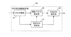
また、MTの受信部51は、直交DRS、非直交DRS、及びデータ信号を含む信号を、アンテナを介して受信し、ダウンコンバージョンしてベースバンドデジタル信号を生成後、信号分離部53に当該ベースバンドデジタル信号を入力する。信号分離部53は、当該ベースバンドデジタル信号を、直交DRS、非直交DRS、及びデータ信号に分離して、DRSをDRS用伝搬路推定部65に、データ信号を伝搬路補償部55に入力する。DRS用伝搬路推定部65は、入力された直交DRSと非直交DRSに基づいて伝搬路を推定して、伝搬路状態を示す情報を伝搬路補償部55に入力する。DRS用伝搬路推定部65の詳細な原理は後述するが、このDRS用伝搬路推定部65によって、図29(b)のように直交DRSが2つ送られてきた場合と同程度の高い精度の伝搬路推定が可能になる。
In addition, the
また、伝搬路補償部55は、伝搬路状態を示す情報を用いて、データ信号を伝搬路補償して、Modulo演算部57に入力する。Modulo演算部57は、データ信号に対してModulo演算を施し、Modulo演算を施されたデータ信号を復調部71に入力する。復調部71は、Modulo演算を施されたデータ信号を復調して、復調結果を復号部73に入力する。復号部73は入力された復調結果を用いて復号を行って情報ビットを出力する。
Further, the propagation
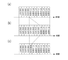
次にMTにおけるDRS用伝搬路推定部について従来の伝搬路推定方法と比較しながら詳細に説明する。従来は、各MT宛のDRSを時間分割多重して送信していた。例えば図5(a)のようなフレーム構成を用いていた。ここで、伝搬路推定精度を上げるためDRSを各MTにもう一回ずつ送ろうとすると図5(b)に示したようなフレーム構成例となる。 Next, the DRS channel estimation unit in MT will be described in detail in comparison with a conventional channel estimation method. Conventionally, DRS addressed to each MT has been time-division multiplexed and transmitted. For example, a frame configuration as shown in FIG. Here, if the DRS is sent to each MT once more in order to improve the propagation path estimation accuracy, a frame configuration example as shown in FIG. 5B is obtained.
しかし、図5(b)に示すように、MT数だけ直交したシンボルが必要であるため、その分、データ信号を送信するためのシンボルが減ってしまい、結果的に送信レートが下がってしまう。 However, as shown in FIG. 5B, since symbols orthogonal to the number of MTs are necessary, the number of symbols for transmitting the data signal is reduced correspondingly, resulting in a decrease in transmission rate.
そこで、図5(c)に示したように、時間分割した直交DRSに加えて非直交DRSを送信する。非直交DRSは1シンボルで全MTにDRSを送信できる。そのためデータ信号を割り当てる領域の減少を最小限に抑えながら、全MTにDRSを2回ずつ送信することができる。 Therefore, as shown in FIG. 5C, non-orthogonal DRS is transmitted in addition to time-divided orthogonal DRS. Non-orthogonal DRS can transmit DRS to all MTs with one symbol. Therefore, DRS can be transmitted twice to all MTs while minimizing the reduction in the area to which the data signal is allocated.
DRS用伝搬路推定部65の一構成例を図4Bに、当該部分の動作を示すフローチャートを図30に示す。ここで、各MTが推定すべき伝搬路をρとおく。(ρは後述する式(15)で表される等価伝搬路RHの各対角成分でrkk *と表される)。送信側では、直交DRSとして受信側でも既知の基準信号qを送信し、また非直交DRSとしてq+dを送信したとする。ここで、図24で説明したように、dは送信側のModulo演算によって加算されたI-ch, Q-ch方向にτの整数倍の大きさを持つ摂動ベクトルであり、本実施の形態においては、送信側の非線形空間多重部内のModulo演算によって加算されたものである。
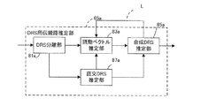
FIG. 4B shows a configuration example of the DRS propagation
また、直交DRSに対する受信信号をyorth、非直交DRSに対応する受信信号をynonorthとする。yorth及びynonorthに含まれる雑音をnorth及びnnonorthとする。ここで、MTは直交DRSが通った伝搬路と非直交DRSが通った伝搬路の変動は無視できるとして伝搬路推定を行う。 Further, the received signal with respect to the orthogonal DRS y orth, the received signal corresponding to a non-orthogonal DRS and y nonorth. The noise included in y orth and y nonorth is defined as no orth and n nonorth . Here, the MT estimates the propagation path on the assumption that fluctuations in the propagation path through which the orthogonal DRS passes and the propagation path through the non-orthogonal DRS can be ignored.
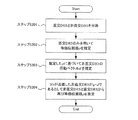
DRS用伝搬路推定部65では、まずDRS分離部81が、入力されたDRSを直交DRSと非直交DRSに分離して、直交DRSyorthを直交DRS推定部87に、非直交DRSynonorthを摂動ベクトル推定部83に入力する(ステップS201)。
In the DRS
その後、直交DRS推定部87が、直交DRSのみを用いて等価伝搬路ρを推定する。推定結果をρorthとすると、
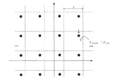
摂動ベクトル推定部83では、MTが受信した非直交DRSynonorthと直交DRS推定部87が推定したρorthを用いて、基準信号と摂動ベクトルの和q+dを推定する。具体的な推定方法を図7に示した。図7中の×印は、ynonorth/ ρorthの値である。また、図7中の●はq+dの候補点を示す。各々の●が格子点上に並んでいるのは、摂動ベクトルdの取り得る値が、I-ch, Q-ch方向にModulo幅t間隔で存在するからである。摂動ベクトル推定部83は、×で示されるynonoorth/ ρorthと最も近い候補点●を、実際BSから送信された非直交DRSであると推定する。図7では、下向きの矢印「↓」で示した●が推定結果として得られるq+dの値であり、d=1・τ+j・1・τとなっている。摂動ベクトル推定部83は、この推定結果q+dと受信した非直交DRS信号ynonorthを合成DRS推定部85に入力する(ステップS203)。
The perturbation
合成DRS推定部85では、直交DRS(基準信号: q 受信信号: yorth)と非直交DRS(基準信号: q+d 受信信号: ynonorth)という2つのDRSを用いて伝搬路推定する。ここでは一例として、最大比合成法で2つのDRSから1つの伝搬路推定結果を算出する。
The combined
この方法を用いれば、図5(c)に示したように、直交DRSに加えて非直交DRSを用いて伝搬路推定をすることができる。直交DRSしか送らない図5(a)と比較して伝送レートの低下を最小限にとどめながら伝搬路推定精度を大きく向上することができる。 If this method is used, as shown in FIG. 5C, it is possible to perform channel estimation using non-orthogonal DRS in addition to orthogonal DRS. Compared to FIG. 5A in which only orthogonal DRS is sent, the propagation path estimation accuracy can be greatly improved while minimizing the decrease in transmission rate.
なお、本実施の形態では、図6(a)に示したように、フレーム内で直交DRSを複数回以上送る場合においても適用可能である。すなわち、図6(b)のように、非直交DRSを加えることで伝送レートの低下を最小限にとどめながら伝搬路推定精度を向上することができる。このとき、各MTは、直交DRS推定部87で、受信した複数の直交DRSを、各々で推定した伝搬路推定値を平均するなど公知の技術により合成して合成DRS推定部85に入力する。なお、非直交DRSをフレーム内で複数回送信する方法については、第2の実施の形態で説明する。
In this embodiment, as shown in FIG. 6A, the present invention can also be applied to a case where orthogonal DRSs are sent a plurality of times within a frame. That is, as shown in FIG. 6B, the non-orthogonal DRS can be added to improve the propagation path estimation accuracy while minimizing the decrease in the transmission rate. At this time, each MT is combined by a known technique such as averaging the estimated channel values estimated by the orthogonal
3)MT数がNの場合
次に、MT数が任意のN個になった場合の線形フィルタ算出部33と非線形空間多重部11について詳細に説明する。MT数が任意のN個になったときでも、MT数が2のときと非線形空間多重部11以外の部分は基本的に同じ構成を持っている。
3) When the MT Number is N Next, the linear
まず、線形フィルタ算出部33の動作を詳細に説明する。ここでBSのq番目の送信アンテナからp番目のMTへの伝搬路の複素利得を表す行列をH (以下、「伝搬路行列」と呼ぶ。) で表す。また、BS側で生成した変調信号をsとおく。sはN次元複素数縦ベクトルであり、sの各成分は、情報ビットに対して符号化と変調を施した変調信号である。図8は、N個のMT宛の信号を計算しているが、このN個のMTを上から順番にMT1〜MTNとおいて、以降の説明を行う。まず線形フィルタ算出部33は、線形フィルタと干渉係数情報とを計算する。具体的には、伝搬路Hのエルミート共役H Hに対してQR分解を施す。
First, the operation of the linear
ここで求めたQを線形フィルタとして線形フィルタ乗算部23に入力する。また、線形フィルタQと実際の伝搬路Hとを合わせたものを、一つの等価的伝搬路としてみることができる。この等価伝搬路は、
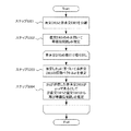
次に、非線形空間多重部11の動作について、非線形空間多重部11の詳細な構成を示す図8とフローチャート図である図9及び図10を用いて詳細に説明する。まず、データ信号が入力されたときの非線形空間多重部11の動作について説明する。最初に処理を開始し(Start)、干渉算出部41が、線形フィルタ算出部33の計算した干渉係数情報を取得する(図9中のステップS1)。その後、1からNまでの値を取る変数kに1を代入する(ステップS2)。その次に、MT1宛のデータ信号s1をv1とおく(ステップS3)。ここで、v1, …, vN は、固有信号構成部21に入力する信号とし、ステップS4からステップS10までの処理でv2, …, vN を計算する。以降、kが2〜Nまでのいずれかの値をとったときの動作を、変数kを用いて一般的に説明する。
Next, the operation of the nonlinear
まず、変数kに1を加算する(k=k+1:ステップS4)。その後、干渉算出部41で、MTkが受ける干渉信号fkを下の式で算出する(ステップS5)。
First, 1 is added to the variable k (k = k + 1: step S4). Thereafter, the
ここで、式(15)のRのp行q列成分をrpqと表した。干渉算出部41は、干渉信号fk をMTkに対応する干渉減算部41−kに入力する。次に、干渉減算部41−kは、データ信号skからfk を減算して、信号sk−fk を算出する(ステップS6)。また干渉減算部41−kは、信号sk−fkをMTkに対応するModulo演算部43−kに入力する。
Here, the p-by-q-column component of R in Expression (15) is expressed as r pq .
Modulo演算部43−2〜Nは、MT2〜MTNまでの各MTに対応する干渉減算部41−2〜Nに接続する形で配置されいる。Modulo演算部43−2〜Nは、入力された信号に対して式(1)で表されるModulo演算を行って算出した信号Mod(sk−fk)をvkとおく(ステップS7)。また、Modulo演算部はvkを干渉算出部に入力する(ステップS8)。k = N であればステップS10に進み、k = NでないならステップS4に戻って次の番号のMTのvk+1を計算する(ステップS9)。最終的に信号v = (v1, v2,…,vN)を固有信号構成部21に入力する(ステップS10)。 The Modulo operation units 43-2 to 43-N are arranged so as to be connected to the interference subtraction units 41-2 to 41-N corresponding to the MTs MT2 to MTN. The Modulo operation units 43-2 to 43-N set the signal Mod (s k −f k ) calculated by performing the Modulo operation represented by the expression (1) on the input signal as v k (step S7). . The Modulo operation unit inputs v k to the interference calculation unit (step S8). If k = N, the process proceeds to step S10. If k = N is not satisfied, the process returns to step S4 to calculate v k + 1 of the next MT (step S9). Finally, the signal v = (v 1 , v 2 ,..., V N ) is input to the unique signal configuration unit 21 (step S10).
また、ここまでは、データ信号が入力されたときの非線形空間多重部11の動作について説明したが、非直交DRSが入力された時もフローチャート図(図10)に示したように全く同じ動作を行う。図10では、データ信号skが非直交DRSqkに、干渉fkが干渉gkに、固有信号構成部21に入力する信号vが信号uに代わっている。
The operation of the nonlinear
尚、非直交DRSとデータ信号でModulo幅が異なることもある。例えば、非直交DRSがデータ信号の送信電力のX倍の送信電力で送信されるときに、Modulo演算部43−2〜Nは、Modulo幅を√X倍にする。またデータ信号の変調方式などによっても適応的に切り替えることが望ましい。 Note that the Modulo width may differ between the non-orthogonal DRS and the data signal. For example, when the non-orthogonal DRS is transmitted with a transmission power that is X times the transmission power of the data signal, the Modulo operation units 43-2 to 43-N increase the Modulo width by √X times. It is also desirable to switch adaptively depending on the data signal modulation method.
<第1の実施の形態の第1変形例>
また、ここまでは、シングルキャリアの場合を述べてきたが、第1の実施の形態は、ダウンリンク、アップリンク、又はその両方でOFDMを行うシステムに対しても適用可能である。ダウンリンクでOFDMを行うときは、第1の実施の形態で説明した方法をサブキャリア毎、または、幾つかのサブキャリアがグループ化された単位毎に行う。
<First Modification of First Embodiment>
Although the case of single carrier has been described so far, the first embodiment can also be applied to a system that performs OFDM in the downlink, the uplink, or both. When performing OFDM in the downlink, the method described in the first embodiment is performed for each subcarrier or for each unit in which several subcarriers are grouped.
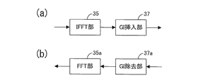
ダウンリンクでOFDM通信を行う場合に、BSの構成には、図1の線形フィルタ乗算部23と各送信部25の間に、図11(a)で表されるIFFT部35とGI(Guard Interval)挿入部37とが挿入される。また、CRS生成部27は、CRSをIFFT部35に入力する。このIFFT部35とGI挿入部37は、送信部25の数だけ存在し、各IFFT部35が線形フィルタ乗算部23と接続しており、各GI挿入部37は、各送信部25−1〜Nに接続している。IFFT部35は、線形フィルタ乗算部23から出力された信号とCRSに対し、IFFTを行い、ベースバンドデジタル信号を作成して、GI挿入部37にベースバンドデジタル信号を入力する。GI挿入部37は、ベースバンドデジタル信号に対し、GIを付加し、GIが付加された信号を送信部25−1〜Nに入力する。この2つの部分以外の動作は上に述べた方式と同様である。
When performing OFDM communication in the downlink, the BS configuration includes an
ダウンリンクでOFDM通信を行う場合に、MTの構成には、図4Aの受信部51と信号分離部53との間に、図11(b)で表されるGI除去部37aとFFT部35aが挿入される。この2つの部分以外の動作は上に述べた方式と同様である。GI除去部37aは、受信部51に入力されたベースバンドデジタル信号からGIを除去し、FFT部35aに入力する。FFT部35aは、GIが除去されたベースバンドデジタル信号に対してFFTを行い、周波数方向の信号を算出した後、当該周波数方向の信号を信号分離部53に入力する。
When performing OFDM communication in the downlink, the MT configuration includes a
アップリンクでOFDM通信を行う場合に、BSの構成には、図1の受信部29−1〜Nと伝搬路情報取得部31との間に図11(b)で表されるGI除去部37aとFFT部35aとが挿入される。このGI除去部37aとFFT部35aとは、送信部25の数Nだけ存在し、各FFT部35aが伝搬路情報取得部31と接続しており、各GI除去部は各受信部に接続している。GI除去部とFFT部の動作は、上記ダウンリンクでOFDM通信を行う場合のGI除去部とFFT部の動作と同じなので、省略する。
When performing OFDM communication in the uplink, the BS configuration includes a
アップリンクでOFDM通信を行う場合に、MTの構成には、図4Aの伝搬路状態情報生成部61と送信部63との間に、図11(a)で表されるIFFT部35とGI挿入部37とが挿入される。IFFT部35とGI挿入部37の動作は、上記アップリンクでOFDM通信を行う場合のIFFT部とGI挿入部の動作と同じであり、その説明を省略する。
When performing OFDM communication in the uplink, the MT configuration includes
また、図5(c)では、時間方向に各DRSとデータ信号を配置したが、OFDM通信を行う場合は、時間方向だけでなく、周波数方向に各DRSとデータ信号を配置しても良いし、時間と周波数方向の両方に配置しても良い。 In FIG. 5C, each DRS and data signal are arranged in the time direction. However, when OFDM communication is performed, each DRS and data signal may be arranged not only in the time direction but also in the frequency direction. It may be arranged in both time and frequency directions.
尚、本実施の形態で示した線形フィルタ算出方法以外にも、上記非特許参考文献2に記載されているMMSE規範に基づく線形フィルタを用いたMU-MIMO THPに対して本実施の形態を適用しても良いし、同じく、非特許参考文献2に記載されているようにオーダリングを用いた方法でもよい。
In addition to the linear filter calculation method shown in the present embodiment, the present embodiment is applied to the MU-MIMO THP using the linear filter based on the MMSE standard described in
また、最初に信号を算出するMT (フローチャート図(図9)及び図(図10)におけるMT1)は、他のMTから干渉を受けないため、BSが当該MT宛の信号に図8のようにModulo演算を行うこともない。そのため、当該MTにおいては、全てのDRSが直交DRSであるとみなして、各々推定した伝搬路推定値を平均するなど公知の技術により合成してもよい。 In addition, since the MT (MT1 in the flowchart (FIG. 9) and FIG. 10) that calculates the signal first is not interfered with by other MTs, the BS sends the signal addressed to the MT as shown in FIG. No Modulo operation is performed. Therefore, in the MT, all DRSs may be regarded as orthogonal DRSs, and may be combined by a known technique such as averaging the estimated channel estimation values.
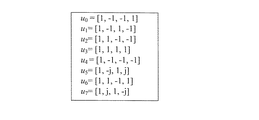
また、MTがCRSに基づいて推定した情報をBSに通知する時に、伝搬路状態を行列で表したHの各成分を示す値を量子化したものをBSに通知しても良い。もしくは、BSとMTが、図23に示したような表 (以下、「Codebook」という。) をあらかじめ共有しておき、MTがCRSに基づいて図23の8個の伝搬路情報の値の中から自分宛の伝搬路に対する0〜7の番号の1つを選択し、BSに選択した番号を通知する方法を用いても良い。もちろん図23に示したCodebookはこれに限られるものではなく、他のCodebookを用いてもよい。
Further, when the information notified by the MT based on the CRS is notified to the BS, the BS may be notified of a quantized value indicating each component of H representing the channel state in a matrix. Alternatively, BS and MT share a table as shown in FIG. 23 (hereinafter referred to as “Codebook”) in advance, and MT is based on CRS among the values of the eight channel information in FIG. Alternatively, a method may be used in which one of
また、本発明でいう「フレーム」とは、(1)DRSと、(2)当該DRSから推定した伝搬路推定結果を利用して復調・復号処理を行う信号を少なくとも含むものであって、時間方向若しくは周波数方向又はその両方で一定の幅を持った単位のことをいう。また、必ずしも一般的な意味の「フレーム」や、仕様書などに定義されている「フレーム」と一致することを必要としない。 In addition, the “frame” in the present invention includes (1) DRS and (2) at least a signal to be demodulated / decoded using a channel estimation result estimated from the DRS, A unit having a certain width in the direction and / or the frequency direction. Further, it does not necessarily need to match a “frame” having a general meaning or a “frame” defined in a specification or the like.
(チップクレームに関する説明)
また、上記方法のBSに係る機能は図1に示したように、プロセッサ1内で実行されてもよい。当該プロセッサ1は本願発明の方法を実行するDRS生成部、直交多重部、非線形空間多重部、及び送信部以外に、受信部、伝搬路情報取得部、CRS生成部、データ信号生成部を持っているがこれに限定されず、DRS生成部、非線形空間多重部、直交多重部、及び送信部のみからなっていてもよく、これらや他の機能を併せ持つような構成でもよく、限定されない。また、上記方法のMTに係る機能は図4Aに示したようにプロセッサ2内で実行されてもよい。当該プロセッサは本願の方法を実行する受信部及びDRS用伝搬路推定部以外に、信号分離部、伝搬路補償部、CRS用伝搬路推定部、伝搬路状態情報生成部、送信部、Modulo演算部、復調部、復号部を持っているがこれに限定されず、受信部及びDRS用伝搬路推定部のみからなっていてもよく、これらや他の機能を併せ持つような構成でもよく、限定されない。
(Explanation regarding chip claims)
Further, the function related to the BS of the above method may be executed in the
また、プロセッサは、半導体等のチップにより構成されても良く、その場合に、モノリシックIC又はハイブリッドICの形態又はそれらの組み合わせであっても良い。 Further, the processor may be configured by a chip such as a semiconductor, and in that case, it may be in the form of a monolithic IC or a hybrid IC or a combination thereof.
<第2の実施の形態>
上記第1の実施の形態では、非直交DRSを1つ用いて伝搬路推定を行う方法について説明した。本実施の形態では、複数の非直交DRSを合成して伝搬路推定を行う方法について説明する。
<Second Embodiment>
In the first embodiment, the method for performing propagation path estimation using one non-orthogonal DRS has been described. In this embodiment, a method for performing propagation path estimation by combining a plurality of non-orthogonal DRSs will be described.
本実施の形態におけるデータ信号、直交DRS、及び非直交DRSのフレーム構成は、第1の実施の形態と異なり、例えば図12のように表される。また、本実施の形態のBSの構成は、第1の実施の形態と同様に図1で表すことができる。MTの構成は、第1の実施の形態と同様に図4Aで表される。但し、DRS用伝搬路推定部65の構成が、図13に示した構成に置き換わる。図13は、図4Bと異なり、合成DRS推定部85aと摂動ベクトル推定部83aとの間で伝搬路推定を繰り返し行う(符号L)。このプロセスは、具体的にはフローチャート図(図14)で示される。以下、図13に示したDRS用伝搬路推定部に対応する図14の動作を、第1の実施の形態のフローチャート図(図30)と比較しながら説明する。まずDRS分離部81aが、入力されたDRSを直交DRSと非直交DRSに分離して、直交DRSを直交DRS推定部87aに、非直交DRSを摂動ベクトル推定部83aに入力する(ステップS301)。その後、直交DRS推定部87aが先に伝搬路推定を行い、直交DRSのみを用いて等価伝搬路ρを推定する(ステップS302)。ステップS301とステップS302は、第1の実施の形態におけるステップS201とステップS202の動作と同様である。次に、摂動ベクトル推定部83aは、受信した非直交DRS信号のうちの1つ(以下、「非直交DRS1」と呼ぶ。)と等価伝搬路ρを用いて、第1の実施の形態におけるステップS203と同様に、非直交DRS1の摂動ベクトルを推定して、基準信号と摂動ベクトルとの和(第1の実施の形態においてq+dという形で表したもの)、及び、実際の非直交DRS1の受信信号を合成DRS推定部85aに入力する(ステップS303)。その後、合成DRS推定部85aでは、直交DRSと非直交DRS1という2つのDRSを用いてステップS204と同様に伝搬路推定する。合成DRS推定部85aは、この値ρを出力して、再び摂動ベクトル挿入部83aに入力する(ステップS304)。
The data signal, orthogonal DRS, and non-orthogonal DRS frame configurations in the present embodiment are different from those in the first embodiment, and are represented as shown in FIG. 12, for example. Moreover, the structure of BS of this Embodiment can be represented by FIG. 1 similarly to 1st Embodiment. The configuration of the MT is represented in FIG. 4A as in the first embodiment. However, the configuration of the DRS propagation
次に、摂動ベクトル推定部83aは、ステップS304で推定したρを用いて、先ほど推定した非直交DRS1以外の非直交DRSのうち1つ(以下、「非直交DRS2」と呼ぶ。)の摂動ベクトルを推定し、基準信号と摂動ベクトルの和及び非直交DRS2の受信信号を合成DRS推定部に入力する(ステップS303)。
Next, the perturbation
合成DRS推定部85aでは、直交DRS、非直交DRS1、非直交DRS2の3つを合成して伝搬路推定を行い、新たに伝搬路推定値ρを算出する(ステップS304)。このときのrは、非直交DRS1と直交DRSのみから推定した時よりも伝搬路推定精度は向上している。以降、図14に示すように、非直交DRSの数だけステップS303とステップS304を繰り返すことで徐々に伝搬路推定精度を向上させることができる。
The combined
上記方法により、推定する順番が後に行くほど、高い伝搬路推定精度で摂動ベクトルの推定ができるため、摂動ベクトル推定部で摂動ベクトルの推定を誤ってしまう可能性を最小限に抑えることができる。 According to the above method, the perturbation vector can be estimated with higher propagation path estimation accuracy as the estimation order is later, so that the possibility that the perturbation vector estimation unit erroneously estimates the perturbation vector can be minimized.
<第1の変形例>
上記第2の実施の形態では、ここまでは、シングルキャリアの場合を述べてきたが、第1の実施の形態と同様にはダウンリンク、アップリンク、又はその両方でOFDMを行うシステムに対しても適用可能である。ダウンリンクでOFDMを行うときは、実施例1で説明した方法をサブキャリア毎に行う。
<First Modification>
In the second embodiment, the case of a single carrier has been described so far. However, as in the first embodiment, for a system that performs OFDM in the downlink, the uplink, or both. Is also applicable. When performing OFDM in the downlink, the method described in the first embodiment is performed for each subcarrier.
ダウンリンクでOFDM通信を行う場合に、BSの構成には、図1の線形フィルタ乗算部23と各送信部25の間に、図11(a)で表されるIFFT部35とGI(Guard Interval)挿入部37が挿入される。またCRS生成部27は、CRSをIFFT部35に入力する。このIFFT部35とGI挿入部37は、送信部25の数だけ設けられ、各IFFT部35が線形フィルタ乗算部23と接続しており、各GI挿入部37は各送信部25に接続している。IFFT部35は、線形フィルタ乗算部23から出力された信号とCRSに対し、IFFTを行い、ベースバンドデジタル信号を作成して、GI挿入部37にベースバンドデジタル信号を入力する。GI挿入部37は、ベースバンドデジタル信号に対し、GIを付加し、GIが付加された信号を送信部25に入力する。この2つの部分以外の動作は上に述べた方式と同様である。
When performing OFDM communication in the downlink, the BS configuration includes an
ダウンリンクでOFDM通信を行う場合に、MTの構成には、図4Aの受信部51と信号分離部53との間に、図11(b)で表されるGI除去部37aとFFT部35aが挿入される。この2つの部分以外の動作は、上に述べた方式と同様である。GI除去部37aは、受信部51に入力されたベースバンドデジタル信号からGIを除去し、FFT部35aに入力する。FFT部35aはGIが除去されたベースバンドデジタル信号に対してFFTを行い、周波数方向の信号を算出した後、当該周波数方向の信号を信号分離部53に入力する。
When performing OFDM communication in the downlink, the MT configuration includes a
アップリンクでOFDM通信を行う場合に、BSの構成には、図1の受信部29と伝搬路情報取得部31との間に図11(b)で表されるGI除去部37aとFFT部35aが挿入される。このGI除去部37aとFFT部35aは受信部29の数だけ存在し、各FFT部35aが信号分離部53と接続しており、各GI除去部37aは各受信部29に接続している。GI除去部37aとFFT部35aの動作は、上記ダウンリンクでOFDM通信を行う場合のGI除去部とFFT部の動作と同じであるため、説明を省略する。
When performing OFDM communication in the uplink, the BS configuration includes a
アップリンクでOFDM通信を行う場合に、MTの構成には、図4Aの伝搬路状態情報生成部61と送信部63との間に図11(a)で表されるIFFT部35とGI挿入部37とが挿入される。IFFT部35とGI挿入部37の動作は、上記アップリンクでOFDM通信を行う場合のIFFT部35とGI挿入部37の動作と同じであり、説明を省略する。
When performing OFDM communication in the uplink, the MT configuration includes an
また、図5(c)では、時間方向に各DRSとデータ信号を配置したが、OFDM通信を行う場合は、時間方向だけでなく、周波数方向に各DRSとデータ信号を配置しても良いし、時間と周波数方向の両方に配置しても良い。 In FIG. 5C, each DRS and data signal are arranged in the time direction. However, when OFDM communication is performed, each DRS and data signal may be arranged not only in the time direction but also in the frequency direction. It may be arranged in both time and frequency directions.
例えば、図15から図17までに示したようなフレーム構成でもよい。図15から図17までは、横軸に時間方向に連続なOFDMシンボル、縦軸に周波数方向に並べたサブキャリアを示している。図15のように、直交DRS(DRS-MT1〜DRS-MT4)を周波数分割多重し、さらに非直交DRSも周波数分割多重するフレーム構成を用いても良いし、図16のように、周波数方向に直交DRSと非直交DRSを多重しても良いし、図17のように周波数と時間の両方向に多重する方法でもよい。なお、図16(a)や図17(b)では、非直交DRSは、全MTから参照される信号となるので、フレームの中心部分に配置することで全体として伝搬路推定精度を向上している。尚、本実施の形態で示した線形フィルタ算出方法以外にも、非特許参考文献2記載されているMMSE規範に基づいた線形フィルタ算出方法を用いるMU-MIMO THPに対して本実施の形態を適用しても良いし、同じく、上記非特許参考文献2記載されているようにオーダリングを用いた方法でもよい。
For example, the frame configuration shown in FIGS. 15 to 17 may be used. 15 to 17, the horizontal axis indicates OFDM symbols continuous in the time direction, and the vertical axis indicates subcarriers arranged in the frequency direction. A frame configuration in which orthogonal DRSs (DRS-MT1 to DRS-MT4) are frequency division multiplexed as shown in FIG. 15 and non-orthogonal DRSs are also frequency division multiplexed may be used, or in the frequency direction as shown in FIG. Orthogonal DRS and non-orthogonal DRS may be multiplexed, or a method of multiplexing in both frequency and time directions as shown in FIG. In FIGS. 16 (a) and 17 (b), the non-orthogonal DRS is a signal that is referenced from all MTs, so that the channel estimation accuracy as a whole is improved by placing it in the center of the frame. Yes. In addition to the linear filter calculation method shown in the present embodiment, this embodiment is applied to MU-MIMO THP that uses a linear filter calculation method based on the MMSE norm described in
また、MTがCRSに基づいて推定した情報をBSに通知する時に、伝搬路状態を行列で表したHの各成分を示す値を量子化したものをBSに通知しても良い。もしくは、BSとMTが、図23に示したような表(以下、「Codebook」という。)をあらかじめ共有しておき、MTがCRSに基づいて図23の8個の伝搬路情報の値の中から自分宛の伝搬路に対する0〜7の番号の1つを選択し、BSに選択した番号を通知する方法を用いても良い。もちろん図23に示したCodebookはこれに限られるものではなく、他のCodebookを用いてもよい。
Further, when the information notified by the MT based on the CRS is notified to the BS, the BS may be notified of a quantized value indicating each component of H representing the channel state in a matrix. Alternatively, BS and MT share a table as shown in FIG. 23 (hereinafter referred to as “Codebook”) in advance, and MT is based on CRS among the values of the eight channel information in FIG. Alternatively, a method may be used in which one of
また、上記方法のMTに係る機能は図4Aに示したようにプロセッサ2内で実行されてもよい。当該プロセッサは、本願の方法を実行する受信部及びDRS用伝搬路推定部以外に、信号分離部、伝搬路補償部、CRS用伝搬路推定部、伝搬路状態情報生成部、送信部、Modulo演算部、復調部、復号部を持っているがこれに限定されず、受信部及びDRS用伝搬路推定部のみからなっていてもよく、これらや他の機能を併せ持つような構成でもよく、限定されない。
Further, the function relating to MT of the above method may be executed in the
<第3の実施の形態>
第1の実施の形態と第2の実施の形態においては、各MTが1つのデータ信号を同一時刻・同一周波数で受信する単一ストリーム通信の場合について説明した。本発明は、図28に示すような、複数ストリームで通信するMT同士を空間多重する状況にも適用できる。
<Third Embodiment>
In the first embodiment and the second embodiment, the case of single stream communication in which each MT receives one data signal at the same time and the same frequency has been described. The present invention can also be applied to a situation in which MTs communicating with a plurality of streams are spatially multiplexed as shown in FIG.
以下、この場合についてBS、MTの構成例を、図面を参照しながら説明する。第1の実施の形態、第2の実施の形態と同様に、先に基本的なシングルキャリア通信について説明した後に、変形例においてOFDMに拡張する場合を説明する。また、本実施の形態では、一例として各MTがMストリームずつ通信する場合について説明するが、これに限られるものではなく、各MTの通信ストリーム数が異なっていても良い。 Hereinafter, a configuration example of the BS and MT will be described with reference to the drawings. Similar to the first embodiment and the second embodiment, the basic single carrier communication will be described first, and then a case of extending to OFDM in a modification will be described. In this embodiment, a case where each MT communicates with M streams as an example will be described. However, the present invention is not limited to this, and the number of communication streams of each MT may be different.
本実施の形態のBS及びMTの動作は、第1の実施の形態及び第2の実施の形態と比較して、以下の4点が異なる。
(i)線形フィルタの算出方法
(ii)Mストリーム毎に逐次的に干渉除去する点
(iii)BSが受信フィルタをMTに通知する点
(iv)MTが受信フィルタを取得して受信信号に対して乗算する点
The BS and MT operations of the present embodiment differ from the first and second embodiments in the following four points.
(i) Linear filter calculation method
(ii) Sequential interference cancellation for each M stream
(iii) BS notifies reception filter to MT
(iv) The point that the MT acquires the reception filter and multiplies the reception signal
(i)線形フィルタの算出方法について
本実施の形態におけるBSの構成例を図18に示した。図18は、第1の実施の形態における図1と同様に、線形フィルタと干渉係数情報を算出する線形フィルタ算出部33を有している。本実施の形態における線形フィルタ算出部33は、線形フィルタと干渉係数情報に加えて、受信フィルタを算出して受信フィルタ情報生成部32aに入力する。この線形フィルタ算出部33の動作は第1の実施の形態と異なるため、後に詳細に記述する。
(i) Linear filter calculation method FIG. 18 shows a configuration example of a BS in the present embodiment. 18 includes a linear filter and a linear
(ii)Mストリーム毎に逐次的に干渉除去する点について
第1の実施の形態と第2の実施の形態に示した非線形空間多重部においては、1ストリーム単位で干渉除去していたものを、Mストリーム単位(すなわちMT単位)で干渉除去する。そのため、干渉算出部、干渉減算部、Modulo演算部はそれぞれMストリーム単位で信号を算出する。
(ii) Points for sequentially canceling interference for each M stream In the nonlinear spatial multiplexing units shown in the first embodiment and the second embodiment, what has been subjected to interference cancellation in units of one stream, Interference cancellation is performed in units of M streams (that is, in units of MT). Therefore, the interference calculation unit, the interference subtraction unit, and the Modulo calculation unit each calculate a signal in units of M streams.
図8に示した非線形空間多重部を使ってMストリーム単位での信号を算出方法を説明する。第1、第2の実施の形態では、図8の結線すべて1つのデータストリームが通ることを示していたが、本実施の形態では、各結線でM本ずつのデータストリームが通る。図18では、データ信号生成部3から入力されるデータストリームの数がMN本になっている。そのデータ信号生成部3から信号の入力を受ける非線形空間多重部(図8)の結線はN本である。これはM本ずつデータストリームが通っているからである。
A method for calculating a signal in units of M streams using the nonlinear spatial multiplexing unit shown in FIG. 8 will be described. In the first and second embodiments, it has been shown that one data stream passes through all the connections in FIG. 8, but in this embodiment, M data streams pass through each connection. In FIG. 18, the number of data streams input from the data signal
本実施の形態では、非線形空間多重部は、MT1宛のM本のデータストリームをまとめて、干渉算出部41に入力した後、干渉算出部が、MT2のM本の各ストリームそれぞれに対応するM個の干渉信号を算出して、干渉減算部41−2に入力する。その後、干渉減算部41−2はMT2宛のM本のデータストリームから、各ストリームそれぞれに対応するM個の干渉信号を減算して、減算したM本の信号をModulo演算部43−2に入力する。Modulo演算部43−2は、M本それぞれに対して式(1)で表されるModulo演算を施す。Modulo演算部43−2は、算出したM本のModulo演算後信号を干渉算出部に入力するとともに、線形フィルタ乗算部23aに入力する。
In the present embodiment, the nonlinear spatial multiplexing unit collects M data streams addressed to MT1 and inputs them to the
このように、第1、第2の実施の形態は、順番に干渉を除去していく処理を1ストリームずつ行うが、本実施の形態はM本ずつまとめて行う。このようにM本ずつ処理することが、第3の実施の形態の特徴である。 As described above, in the first and second embodiments, the process of sequentially removing the interference is performed one stream at a time, but in the present embodiment, M is performed collectively. It is a feature of the third embodiment that M is processed in this way.
(iii)受信フィルタを通知する点について
また、BSはMストリーム毎に各MT宛に同時に信号を送信するため、MTが受信したM本のストリームを分離できるようにする必要がある。そのため、BSが算出した受信フィルタを、各MTに通知する。MTは、この受信フィルタを、受信した自分宛の信号に対して乗算する。
(iii) Regarding notification of reception filter Further, since the BS simultaneously transmits a signal to each MT for each M stream, it is necessary to be able to separate M streams received by the MT. Therefore, the reception filter calculated by the BS is notified to each MT. The MT multiplies this reception filter by the received signal addressed to itself.
また、図18において、受信フィルタ情報生成部32aが新たに追加されていることがわかる。受信フィルタ情報生成部32aは、受信フィルタ情報を生成し、固有信号構成部21に入力する。固有信号構成部21は、非直交データ信号、非直交DRS、及び直交DRSを用いて固有信号を構成していたところにおいて、さらに受信フィルタ情報も含む固有信号を構成し、構成した固有信号を線形フィルタ乗算部23aに入力する。
Further, in FIG. 18, it can be seen that a reception filter
固有信号の構成は、例えば、図21のようになる。図21に示した固有信号には、各MT宛の受信フィルタ情報、各MT宛の直交DRS、非直交DRS、及びデータ信号が含まれる。各直交DRSは、受信フィルタを乗算することで分離できるため、同一MTに送信するものは空間多重できる。また、非直交DRSも同様に、受信フィルタを乗算することで分離できるため、データ信号と同様に、全てのMT宛の全ストリームに対応するDRSを空間多重できる。 The configuration of the unique signal is, for example, as shown in FIG. The unique signal shown in FIG. 21 includes reception filter information addressed to each MT, orthogonal DRS, non-orthogonal DRS, and data signal addressed to each MT. Since each orthogonal DRS can be separated by multiplying by a reception filter, those transmitted to the same MT can be spatially multiplexed. Similarly, since non-orthogonal DRSs can be separated by multiplying by reception filters, DRSs corresponding to all streams destined for all MTs can be spatially multiplexed in the same manner as data signals.
(iv)MTが受信フィルタを取得して受信信号に対して乗算する点
本実施の形態におけるMTの構成を図19に示した。図19は、M本のアンテナを持つMTの構成について示している。本実施の形態におけるMTは、第1の実施の形態のMTの構成と比較して、アンテナ数、受信部、及び送信部がM個に増えて、受信フィルタ乗算部52aと受信フィルタ取得部52bが新たに設けられている。
(iv) Point where MT acquires reception filter and multiplies reception signal MT configuration in this embodiment is shown in FIG. FIG. 19 shows the configuration of an MT having M antennas. Compared with the MT configuration of the first embodiment, the number of antennas, the number of reception units, and the number of transmission units are increased to M in the present embodiment, and the reception
データ信号、非直交DRS、直交DRS、及び受信フィルタ情報からなるMストリームの信号を受信したMTは、まず、受信フィルタ取得部52bで受信フィルタ情報から受信フィルタを取得する。受信フィルタ取得部52bは、取得した受信フィルタを受信フィルタ乗算部52aに入力する。受信フィルタ乗算部52aは、受信信号のうち、データ信号、非直交DRS、及び直交DRSに対して受信フィルタを乗算することで、Mストリームの信号を全て分離することができる。また、受信フィルタ乗算部52aは、分離したMストリームの信号を信号分離部53に入力する。以後、MTは各ストリームを完全に独立したものとして扱うことができる。
The MT that has received the M stream signal including the data signal, the non-orthogonal DRS, the orthogonal DRS, and the reception filter information first acquires the reception filter from the reception filter information by the reception
信号分離部53以降の動作は、第1の実施の形態又は第2の実施の形態と同様である。ただし、分離したMストリーム毎に信号分離、伝搬路推定などの処理を行う。また、CRSを受信するフレームに対しては、伝搬路状態を推定するため、受信フィルタ乗算部52aは何のフィルタも乗算せずにそのままCRSを信号分離部53に入力する。
The operations after the
以上の4点が、本実施の形態における、第1の実施の形態と第2の実施の形態からの変更点である。以下に線形フィルタ算出部52aの線形フィルタ、干渉係数情報、受信フィルタの算出方法について説明する。
The above four points are changes in the present embodiment from the first embodiment and the second embodiment. The linear filter, interference coefficient information, and reception filter calculation method of the linear
本実施の形態に係る線形フィルタ算出部33は、i)Null Spaceの算出、ii)MT個別フィルタの算出、iii)線形フィルタの算出、iv)干渉係数フィルタの算出の4つのプロセスを実行する。最終的に、線形フィルタ算出部33は、線形フィルタ乗算部33に線形フィルタを、干渉算出部41に干渉係数情報を、受信フィルタ情報生成部32aに受信フィルタを入力する。
The linear
ここで、線形フィルタ算出部33の動作を簡単に説明するため、まず2本のアンテナを持つMTが2つ(M=2, N=2)、BSの送信アンテナが4つ(MN=4)のときについて説明する。
Here, in order to briefly describe the operation of the linear
i)Null Spaceの算出
MT2の信号に対して乗算する線形フィルタであって、図20に示したように、MT2宛の信号がMT1に届かない状態にするフィルタを、Null Spaceという。BSの各送信アンテナからk番目のMTの受信アンテナまでの伝搬路の複素利得を2×4行列Hkで表す。ここでkはオーダリング後におけるMTの番号である。ここでは、全体の伝搬路行列は、
A linear filter that multiplies the MT2 signal and makes the signal addressed to MT2 not reach MT1 as shown in FIG. 20 is called a null space. The complex gain of the propagation path from each BS transmit antenna to the kth MT receive antenna is represented by a 2 × 4 matrix H k . Here, k is the MT number after ordering. Here, the overall channel matrix is
ここで、式(18)の右辺の左から1つ目の行列、及び3つ目の行列はそれぞれユニタリ行列である。また2つ目の行列は1行1列成分と2行2列成分だけが正の実数となる。3つ目の行列の3行目と4行目に相当する行列のエルミート共役を、 Here, the first matrix and the third matrix from the left of the right side of Equation (18) are each a unitary matrix. In the second matrix, only the 1 × 1 component and the 2 × 2 component are positive real numbers. The Hermitian conjugate of the matrix corresponding to the third and fourth rows of the third matrix,
ii)MT個別フィルタの算出
ii) Calculation of MT individual filter
iii)線形フィルタの算出
iv)干渉係数フィルタの算出
HPを等価的伝搬路とすると
iv) Interference coefficient filter calculation
If HP is an equivalent propagation path
BSはこの等価伝搬路Tを用いて干渉係数フィルタを算出する。干渉係数フィルタは、等価伝搬路Tを用いてMT2が伝搬路を補償した後に残留する干渉成分を、算出するためのフィルタてある。等価伝搬路Tの一部分のT21は、MT1宛の信号がMT2に及ぼす干渉となる信号が通る伝搬路を示している。しかし、TはMT2が伝搬路を補償する前の干渉成分を示しているため、本方式では、伝搬路補償した後の干渉信号の伝搬路を、算出することが必要である。 The BS calculates an interference coefficient filter using this equivalent propagation path T. The interference coefficient filter is a filter for calculating an interference component remaining after MT2 compensates the propagation path using the equivalent propagation path T. T 21 in a part of the equivalent propagation path T indicates a propagation path through which a signal serving as interference that the signal addressed to MT1 has on MT2 passes. However, since T represents an interference component before MT2 compensates the propagation path, in this method, it is necessary to calculate the propagation path of the interference signal after propagation path compensation.
いま、データ信号の伝搬路のみを取り出すと、
以上の計算により、干渉係数情報B−1T−Iと線形フィルタPを求めることができる。以上のようにして計算した干渉係数フィルタを干渉算出部とModulo演算切り換え部に入力し、線形フィルタを線形フィルタ乗算部に入力する。また受信フィルタは式(2-6)と式(2-7)の右辺の左から1つ目の行列のエルミート共役である。すなわち、
ここまでは、2本のアンテナを持つMTが2つ、BSの送信アンテナが4つのときについて説明したが、次に、線形フィルタ算出部の動作を、M本のアンテナを持つMTがN個有る場合について一般化して説明する。 Up to this point, the case where there are two MTs with two antennas and four BS transmission antennas has been described. Next, the operation of the linear filter calculation unit has N MTs with M antennas. The case will be generalized and described.
i)Null Spaceの算出
BSの各アンテナからk番目のMTのアンテナまでの伝搬路の複素利得をM×MN行列Hkで表す。ここでkはオーダリング後におけるMTの番号である。つまりH1に対応するMTがTHP非対応MTであり、残りのMTはTHP対応MTである。全体の伝搬路行列は、
i) Calculation of Null Space
The complex gain of the propagation path from each BS antenna to the k-th MT antenna is represented by an M × MN matrix H k . Here, k is the MT number after ordering. That is, the MT corresponding to H 1 is a THP non-compatible MT, and the remaining MTs are THP compatible MTs. The overall channel matrix is
ii)MT個別フィルタの算出
ii) Calculation of MT individual filter
iii)線形フィルタの算出
iv)干渉係数フィルタの算出
HPを等価的伝搬路とすると、
If HP is an equivalent propagation path,
また、受信フィルタの乗算を含めた等価的な伝搬路は、式(30)と式(31)より、
<第1変形例>
上記第3の実施の形態では、ここまでは、シングルキャリアの場合を述べてきたが、実施例1と同様にダウンリンク、アップリンク、又はその両方でOFDMを行うシステムに対しても適用可能である。
<First Modification>
In the third embodiment, the case of a single carrier has been described so far, but it can also be applied to a system that performs OFDM in the downlink, the uplink, or both as in the first embodiment. is there.
ダウンリンクでOFDM通信を行う場合に、BSの構成には、図18の線形フィルタ乗算部23aと各送信部25の間に図11(a)で表されるIFFT部35とGI(Guard Interval)挿入部37が挿入される。またCRS生成部27は、CRSをIFFT部35に入力する。このIFFT部35とGI挿入部37は送信部25の数MNだけ存在し、各IFFT部35が線形フィルタ乗算部23aと接続しており、各GI挿入部37は各送信部25に接続している。IFFT部35は、線形フィルタ乗算部23aから出力された信号とCRSに対し、IFFTを行い、ベースバンドデジタル信号を作成して、GI挿入部37にベースバンドデジタル信号を入力する。GI挿入部37は、ベースバンドデジタル信号に対し、GIを付加し、GIが付加された信号を送信部25に入力する。この2つの部分以外の動作は上に述べた方式と同様である。
When performing OFDM communication in the downlink, the BS configuration includes an
ダウンリンクでOFDM通信を行う場合に、MTの構成には、図19の受信部51と受信フィルタ乗算部52aの間に図11(b)で表されるGI除去部37aとFFT部35aが挿入される。この2つの部分以外の動作は上に述べた方式と同様である。GI除去部37aは、受信部51に入力されたベースバンドデジタル信号からGIを除去し、FFT部35aに入力する。FFT部35aはGIが除去されたベースバンドデジタル信号に対してFFTを行い、周波数方向の信号を算出した後、当該周波数方向の信号を受信フィルタ乗算部52aに入力する。
When performing OFDM communication in the downlink, the
アップリンクでOFDM通信を行う場合に、BSの構成には、図18の受信部29と伝搬路情報取得部31の間に図11(b)で表されるGI除去部37aとFFT部35aが挿入される。このGI除去部37aとFFT部35aは、受信部25の数MNだけ存在し、各FFT部35aが伝搬路情報取得部31と接続しており、各GI除去部37aは各受信部29に接続している。GI除去部37aとFFT部35aの動作は、上記ダウンリンクでOFDM通信を行う場合のGI除去部37aとFFT部35aの動作と同じであるため、説明を省略する。
When performing OFDM communication in the uplink, the BS configuration includes a
アップリンクでOFDM通信を行う場合に、MTの構成には、図19の伝搬路状態情報生成部61と送信部63の間に図11(a)で表されるIFFT部35とGI挿入部37が挿入される。IFFT部35とGI挿入部37の動作は、上記アップリンクでOFDM通信を行う場合のIFFT部とGI挿入部の動作と同じであるため、その説明を省略する。
When performing OFDM communication in the uplink, the MT configuration includes an
また、図21では、時間方向に各DRSとデータ信号を配置したが、OFDM通信を行う場合は、時間方向だけでなく、周波数方向に各DRSとデータ信号を配置しても良いし、時間と周波数方向の両方に配置しても良い。例えば、直交DRS(DRS-MT1〜DRS-MT4)を周波数分割多重し、さらに非直交DRSも周波数分割多重するフレーム構成用いても良いし、に周波数と時間の両方向に多重する方法でもよい。 In FIG. 21, each DRS and data signal are arranged in the time direction. However, when performing OFDM communication, each DRS and data signal may be arranged not only in the time direction but also in the frequency direction. It may be arranged in both frequency directions. For example, a frame configuration in which orthogonal DRSs (DRS-MT1 to DRS-MT4) are frequency-division multiplexed and non-orthogonal DRSs are also frequency-division multiplexed may be used, or a method of multiplexing in both frequency and time directions may be used.
<第2の変形例>
本実施の形態においては、(iii)に述べたように、BSが受信フィルタを送信し、MTがこの受信フィルタを用いてDRS及びデータ信号を各々のストリームに分離する方法ついて説明した。本第2の変形例は、BSがこの受信フィルタに関する情報を送らずに、MTがデータ信号を各々のストリームに分離する方法について説明する。
<Second Modification>
In the present embodiment, as described in (iii), a method has been described in which a BS transmits a reception filter, and an MT uses this reception filter to separate a DRS and a data signal into respective streams. In the second modification, a method will be described in which the MT separates the data signal into each stream without the BS sending information regarding the reception filter.
まず、フレーム構成を図22に示したものとする。図21と比較すると、図22に示した本変形例では、BSが受信フィルタを送信しないかわりに、各MT宛のDRSを、ストリーム毎に直交する無線リソースで送信している。図22では、MT1宛のストリーム1とストリーム2に対応する直交DRS(DRS-MT1、DRS-MT2)を送信し、同様にMT2宛のストリーム3と4に対応する直交DRSを送信する。
First, the frame configuration is as shown in FIG. Compared to FIG. 21, in the present modification shown in FIG. 22, the BS transmits the DRS addressed to each MT using radio resources orthogonal to each stream, instead of transmitting the reception filter. In FIG. 22, orthogonal DRSs (DRS-MT1, DRS-MT2) corresponding to
尚、本実施形態で示した線形フィルタ算出方法以外にも、MMSE規範に基づいた線形フィルタ算出方法を用いるMU-MIMO THPに対して、本実施例を適用しても良いし、非特許参考文献3記載されているようにオーダリングを用いた方法でもよい。 In addition to the linear filter calculation method shown in the present embodiment, this embodiment may be applied to MU-MIMO THP that uses a linear filter calculation method based on the MMSE norm. 3, a method using ordering may be used.
また、MTがCRSに基づいて推定した情報をBSに通知する時に、伝搬路状態を行列で表したHの各成分を示す値を量子化したものをBSに通知しても良い。もしくは、BSとMTが、図23に示したような表(以下、「Codebook」という。)をあらかじめ共有しておき、MTがCRSに基づいて図23の8個の伝搬路情報の値の中から自分宛の伝搬路に対する0〜7の番号の1つを選択し、BSに選択した番号を通知する方法を用いても良い。もちろん図23に示したCodebookはこれに限られるものではなく、他のCodebookを用いてもよい。
Further, when the information notified by the MT based on the CRS is notified to the BS, the BS may be notified of a quantized value indicating each component of H representing the channel state in a matrix. Alternatively, BS and MT share a table as shown in FIG. 23 (hereinafter referred to as “Codebook”) in advance, and MT is based on CRS among the values of the eight channel information in FIG. Alternatively, a method may be used in which one of
また、上記方法のBSに係る機能は図18に示したようにプロセッサ1内で実行されてもよい。当該プロセッサ1は本願の方法を実行するDRS生成部、非線形空間多重部、及び送信部以外に、受信部、伝搬路情報取得部、CRS生成部、受信フィルタ情報生成部、及びデータ信号生成部を持っているがこれに限定されず、DRS生成部、非線形空間多重部、及び送信部のみからなっていてもよく、これらや他の機能を併せ持つような構成でもよく、限定されない。
Further, the function related to the BS of the above method may be executed in the
また、上記方法のMTに係る機能は、図19に示したようにプロセッサ2内で実行されてもよい。当該プロセッサは本願の方法を実行する受信部及びDRS用伝搬路推定部以外に、信号分離部、伝搬路補償部、CRS用伝搬路推定部、伝搬路状態情報生成部、送信部、Modulo演算部、復調部、復号部、受信フィルタ乗算部、及び受信フィルタ取得部を持っているがこれに限定されず、受信部及びDRS用伝搬路推定部のみからなっていてもよく、これらや他の機能を併せ持つような構成でもよく、限定されない。なお、ここでいう、送信モード判別部とは、送信モード取得部のことを示すが、これ以外のものでもよい。
Further, the function relating to the MT of the above method may be executed in the
以下に、上記の実施の形態において共通の点について説明する。
<全実施形態における共通の説明>
上記の各実施の形態において示した基地局装置(BS)及び移動局装置(MT)が備えるアンテナの本数は、説明の便宜上、MTが通信するデータストリーム数と一致させているが、示した本数と、物理的には異なった本数のアンテナを持つMTであってもよい。例えば、あるMTが、物理的に2本のアンテナで信号を受信するが、受信した信号を1つの信号に合成する設計である場合、本発明の記載では、便宜的にアンテナが1本として扱っている。
Hereinafter, common points in the above embodiment will be described.
<Common description in all embodiments>
For convenience of explanation, the number of antennas included in the base station apparatus (BS) and mobile station apparatus (MT) shown in each of the above embodiments is the same as the number of data streams communicated by the MT. Alternatively, an MT having a physically different number of antennas may be used. For example, when an MT is physically designed to receive a signal with two antennas but combines the received signal into one signal, the description of the present invention treats the antenna as one for convenience. ing.
尚、本発明は、必ずしもTHPを用いたDL MU-MIMO通信の全てにおいて用いる必要はなく、受信SNRが高いMTにのみに限って本発明に基づいた方法でDRSを送信するなど、受信品質に応じて部分的に本発明を用いても良い。また、受信品質だけでなく、MTの移動速度や変調方式、符号化率等に応じて部分的に用いても良い。 Note that the present invention is not necessarily used in all DL MU-MIMO communication using THP, and it is possible to improve reception quality such as transmitting DRS by a method based on the present invention only for MT having a high reception SNR. Accordingly, the present invention may be partially used. Moreover, you may use partially according to not only reception quality but the moving speed of MT, a modulation system, a coding rate, etc.
例えば、受信SNRが高いMTは、適応変調符号化(AMC: Adaptive Modulation and Coding)を用いて16QAMや64QAM等の高多値数の変調方式を用いていることが多く、高多値数の変調方式は、信号点間距離が短いため、伝搬路推定精度も要求される。そのため、受信SNRが高いとき、又は高多値数の変調方式で通信を行っている時に、直交DRSに加えて非直交DRSを用いて伝搬路推定精度を高める目的で本発明を用いると有効である。また、高SNRのときに直交DRSにおいて摂動ベクトルの推定誤りが減少するため、本発明がより有効に機能すると考えられる。 For example, MTs with high received SNR often use high-multilevel modulation schemes such as 16QAM and 64QAM using adaptive modulation and coding (AMC). Since the method has a short distance between signal points, propagation path estimation accuracy is also required. Therefore, it is effective to use the present invention for the purpose of improving the propagation path estimation accuracy by using non-orthogonal DRS in addition to orthogonal DRS when the received SNR is high or when communication is performed with a high multilevel modulation scheme. is there. Further, it is considered that the present invention functions more effectively because perturbation vector estimation errors are reduced in orthogonal DRS at high SNR.
さらに、変調方式が64QAM以上の多値数のときは本発明を用いて、多値数が64QAMより少ないときは、直交DRSのみを送信するなどの従来技術を用いると、本発明と従来技術による二つのDRS送信方法からどの方法を用いているという制御情報を新たに送る必要もない。MTは変調方式さえわかれば、どのDRS送信方法を用いるか判別できるからである。 Further, when the modulation scheme is a multi-level number of 64QAM or more, the present invention is used, and when the multi-level number is less than 64QAM, the conventional technique such as transmitting only orthogonal DRS is used. There is no need to newly send control information indicating which method is used from the two DRS transmission methods. This is because the MT can determine which DRS transmission method is used as long as the modulation scheme is known.
本発明に関わる移動局装置および基地局装置で動作するプログラムは、本発明に関わる上記実施形態の機能を実現するように、CPU等を制御するプログラム(コンピュータを機能させるプログラム)である。そして、これら装置で取り扱われる情報は、その処理時に一時的にRAMに蓄積され、その後、各種ROMやHDDに格納され、必要に応じてCPUによって読み出し、修正・書き込みが行なわれる。プログラムを格納する記録媒体としては、半導体媒体(例えば、ROM、不揮発性メモリカード等)、光記録媒体(例えば、DVD、MO、MD、CD、BD等)、磁気記録媒体(例えば、磁気テープ、フレキシブルディスク等)等のいずれであってもよい。また、ロードしたプログラムを実行することにより、上述した実施形態の機能が実現されるだけでなく、そのプログラムの指示に基づき、オペレーティングシステムあるいは他のアプリケーションプログラム等と共同して処理することにより、本発明の機能が実現される場合もある。 The program that operates in the mobile station apparatus and the base station apparatus related to the present invention is a program (a program that causes a computer to function) that controls the CPU and the like so as to realize the functions of the above-described embodiments related to the present invention. Information handled by these devices is temporarily stored in the RAM at the time of processing, then stored in various ROMs and HDDs, read out by the CPU, and corrected and written as necessary. As a recording medium for storing the program, a semiconductor medium (for example, ROM, nonvolatile memory card, etc.), an optical recording medium (for example, DVD, MO, MD, CD, BD, etc.), a magnetic recording medium (for example, magnetic tape, Any of a flexible disk etc. may be sufficient. In addition, by executing the loaded program, not only the functions of the above-described embodiment are realized, but also based on the instructions of the program, the processing is performed in cooperation with the operating system or other application programs. The functions of the invention may be realized.
また市場に流通させる場合には、可搬型の記録媒体にプログラムを格納して流通させたり、インターネット等のネットワークを介して接続されたサーバコンピュータに転送したりすることができる。この場合、サーバコンピュータの記憶装置も本発明に含まれる。また、上述した実施形態における移動局装置および基地局装置の一部、または全部を典型的には集積回路であるLSIとして実現してもよい。移動局装置および基地局装置の各機能ブロックは個別にプロセッサ化してもよいし、一部、または全部を集積してプロセッサ化してもよい。また、集積回路化の手法はLSIに限らず専用回路、または汎用プロセッサで実現しても良い。また、半導体技術の進歩によりLSIに代替する集積回路化の技術が出現した場合、当該技術による集積回路を用いることも可能である。 In the case of distribution in the market, the program can be stored and distributed in a portable recording medium, or transferred to a server computer connected via a network such as the Internet. In this case, the storage device of the server computer is also included in the present invention. Moreover, you may implement | achieve part or all of the mobile station apparatus and base station apparatus in embodiment mentioned above as LSI which is typically an integrated circuit. Each functional block of the mobile station apparatus and the base station apparatus may be individually made into a processor, or a part or all of them may be integrated into a processor. Further, the method of circuit integration is not limited to LSI, and may be realized by a dedicated circuit or a general-purpose processor. In addition, when an integrated circuit technology that replaces LSI appears due to progress in semiconductor technology, an integrated circuit based on the technology can also be used.
以上、この発明の実施形態を、図面を参照して詳述してきたが、具体的な構成はこの実施形態に限られるものではなく、この発明の要旨を逸脱しない範囲の設計等も特許請求の範囲に含まれる。 The embodiment of the present invention has been described in detail with reference to the drawings. However, the specific configuration is not limited to this embodiment, and the design and the like within the scope not departing from the gist of the present invention are also claimed. Included in the range.
本発明は、通信装置に利用可能である。 The present invention is applicable to a communication device.
A…基地局、1…プロセッサ、3…データ信号生成部、5…符号部、7…変調部、11…非線形空間多重部、15…DRS生成部、17…直交多重部、21…固有信号構成部、23…線形フィルタ乗算部、25…送信部、AT…アンテナ、27…CRS生成部、29…受信部、31…伝搬路情報取得部、33…線形フィルタ算出部、B…端末局(MT)、51…受信部、53…信号分離部、55…伝搬路補償部、57…Modulo演算部、61…伝搬路状態情報生成部、63…送信部、65…DRS用伝搬路推定部、71…復調部、73…復号部。 A ... base station, 1 ... processor, 3 ... data signal generation unit, 5 ... coding unit, 7 ... modulation unit, 11 ... nonlinear spatial multiplexing unit, 15 ... DRS generation unit, 17 ... orthogonal multiplexing unit, 21 ... specific signal configuration , 23 ... linear filter multiplier, 25 ... transmitter, AT ... antenna, 27 ... CRS generator, 29 ... receiver, 31 ... propagation path information acquisition unit, 33 ... linear filter calculator, B ... terminal station (MT) , 51... Receiver, 53... Signal separator, 55... Propagation compensator, 57 .. modulo calculator, 61... Propagation state information generator, 63 .. transmitter, 65. ... demodulation unit, 73 ... decoding unit.
Claims (8)
前記伝搬路推定部は、前記直交DRSに基づいて第1の伝搬路推定を行う直交DRS推定部と、前記第1の伝搬路推定結果と前記非直交DRSとに基づいて、当該非直交DRSに加算された摂動ベクトルを推定する摂動ベクトル推定部とを有することを特徴とする受信装置。 A receiver that receives non-orthogonal DRS and orthogonal DRS in which DRSs addressed to a plurality of receiving devices are spatially multiplexed, a propagation path estimation unit that performs propagation path estimation based on at least the non-orthogonal DRS and orthogonal DRS, Have
The propagation path estimation unit performs an orthogonal DRS estimation unit that performs a first propagation path estimation based on the orthogonal DRS, a non-orthogonal DRS based on the first propagation path estimation result and the non-orthogonal DRS. And a perturbation vector estimator for estimating the added perturbation vector.
前記非直交DRS、前記摂動ベクトル、及び、前記直交DRSに基づいて伝搬路推定値を算出する合成DRS推定部と、
を有することを特徴とする請求項1に記載の受信装置。 The propagation path estimator is
A combined DRS estimator that calculates a channel estimation value based on the non-orthogonal DRS, the perturbation vector, and the orthogonal DRS;
The receiving apparatus according to claim 1 , comprising:
前記伝搬路推定部は、
直交DRSに基づいて伝搬路推定値を算出する直交DRS推定部と、
前記伝搬路推定値と複数の前記非直交DRSの一部に基づいて、当該非直交DRSに加算された摂動べクトルをそれぞれ推定する摂動ベクトル推定部と、
前記一部の非直交DRS、前記摂動ベクトル、及び、前記直交DRSに基づいて伝搬路推定値を算出する合成DRS推定部と、
を有することを特徴とする請求項1に記載の受信装置。 The receiving unit receives an orthogonal DRS and a plurality of non-orthogonal DRSs,
The propagation path estimator is
An orthogonal DRS estimator that calculates a channel estimation value based on the orthogonal DRS;
A perturbation vector estimator that estimates the perturbation vector added to the non-orthogonal DRS based on the propagation path estimation value and a part of the non-orthogonal DRS,
A combined DRS estimation unit that calculates a channel estimation value based on the non-orthogonal DRS, the perturbation vector, and the orthogonal DRS;
The receiving apparatus according to claim 1 , comprising:
前記一部の非直交DRS以外の非直交DRSと、前記伝搬路推定値と、に基づいて、当該前記一部の非直交DRS以外の非直交DRSに加算された摂動べクトルをそれぞれ推定することを特徴とする請求項3に記載の受信装置。 The perturbation vector estimation unit includes:
Based on the non-orthogonal DRS other than the part of the non-orthogonal DRS and the propagation path estimation value, each of the perturbation vectors added to the non-orthogonal DRS other than the part of the non-orthogonal DRS is estimated. The receiving apparatus according to claim 3 .
前記送信装置は、
前記各受信装置宛のDRS(固有参照信号)を生成するDRS生成部と、
前記DRSの少なくとも一部からなる第1のグループのDRSを用いて非直交DRSを生成する非線形空間多重部と、
前記DRSの少なくとも一部からなる第2のグループのDRSを用いて直交DRSを生成する直交多重部と、
前記非直交DRSと前記直交DRSを少なくとも1つずつ含んだ信号を送信する送信部と、を有し、
前記受信装置は、
複数の受信装置宛のDRSが空間多重されている非直交DRSと直交DRSとを受信する受信部と、少なくとも前記非直交DRSと直交DRSとに基づいて伝搬路推定を行う伝搬路推定部と、を有し、
前記伝搬路推定部は、前記直交DRSに基づいて第1の伝搬路推定を行う直交DRS推定部と、前記第1の伝搬路推定結果と前記非直交DRSとに基づいて、当該非直交DRSに加算された摂動ベクトルを推定する摂動ベクトル推定部とを有することを特徴とする通信システム。 A communication system comprising a plurality of reception devices and a transmission device that transmits signals to the plurality of reception devices using a plurality of transmission antennas at the same channel and the same time,
The transmitter is
A DRS generator for generating a DRS (unique reference signal) addressed to each receiving device;
A non-orthogonal DRS that generates a non-orthogonal DRS using a first group of DRSs comprising at least a portion of the DRSs;
An orthogonal multiplexing unit that generates an orthogonal DRS using a DRS of a second group including at least a part of the DRS;
A transmitter that transmits a signal including at least one of the non-orthogonal DRS and the orthogonal DRS, and
The receiving device is:
A receiver that receives non-orthogonal DRS and orthogonal DRS in which DRSs addressed to a plurality of receiving devices are spatially multiplexed, a propagation path estimation unit that performs propagation path estimation based on at least the non-orthogonal DRS and orthogonal DRS, Have
The propagation path estimation unit performs an orthogonal DRS estimation unit that performs a first propagation path estimation based on the orthogonal DRS, a non-orthogonal DRS based on the first propagation path estimation result and the non-orthogonal DRS. And a perturbation vector estimation unit that estimates the added perturbation vector.
少なくとも前記非直交DRSと前記直交DRSとに基づいて伝搬路推定を行うステップと、を有し、
前記伝搬路推定を行うステップは、前記直交DRSに基づいて第1の伝搬路推定を行うステップと、前記第1の伝搬路推定結果と前記非直交DRSとに基づいて、当該非直交DRSに加算された摂動ベクトルを推定するステップとを有することを特徴とする受信方法。 Receiving non-orthogonal DRS and orthogonal DRS in which DRSs addressed to a plurality of receiving devices are spatially multiplexed;
Performing channel estimation based on at least the non-orthogonal DRS and the orthogonal DRS, and
The step of performing the propagation path estimation includes adding a first propagation path estimation based on the orthogonal DRS, adding to the non-orthogonal DRS based on the first propagation path estimation result and the non-orthogonal DRS. Estimating the perturbation vector thus obtained.
複数の受信装置宛のDRSが空間多重されている非直交DRSと直交DRSとを受信する受信部と、
少なくとも前記非直交DRSと前記直交DRSとに基づいて伝搬路推定を行う伝搬路推定部と、を有し、
前記伝搬路推定部は、前記直交DRSに基づいて第1の伝搬路推定を行う直交DRS推定部と、前記第1の伝搬路推定結果と前記非直交DRSとに基づいて、当該非直交DRSに加算された摂動ベクトルを推定する摂動ベクトル推定部とを有することを特徴とするプロセッサ。 A processor used in a receiving device,
A receiving unit that receives a non-orthogonal DRS and an orthogonal DRS in which DRSs addressed to a plurality of receiving devices are spatially multiplexed,
A channel estimation unit that performs channel estimation based on at least the non-orthogonal DRS and the orthogonal DRS;
The propagation path estimation unit performs an orthogonal DRS estimation unit that performs a first propagation path estimation based on the orthogonal DRS, a non-orthogonal DRS based on the first propagation path estimation result and the non-orthogonal DRS. And a perturbation vector estimation unit for estimating the added perturbation vector.
Priority Applications (5)
| Application Number | Priority Date | Filing Date | Title |
|---|---|---|---|
| JP2010043830A JP5501034B2 (en) | 2010-03-01 | 2010-03-01 | Communication system, transmitter, receiver |
| US13/582,374 US8897122B2 (en) | 2010-03-01 | 2011-01-31 | Communication system, transmitter and receiver |
| EP11750432.4A EP2544393A4 (en) | 2010-03-01 | 2011-01-31 | Communication system, transmission device, reception device |
| CN2011800116110A CN102783069A (en) | 2010-03-01 | 2011-01-31 | Communication system, transmission device, reception device |
| PCT/JP2011/051854 WO2011108319A1 (en) | 2010-03-01 | 2011-01-31 | Communication system, transmission device, reception device |
Applications Claiming Priority (1)
| Application Number | Priority Date | Filing Date | Title |
|---|---|---|---|
| JP2010043830A JP5501034B2 (en) | 2010-03-01 | 2010-03-01 | Communication system, transmitter, receiver |
Publications (3)
| Publication Number | Publication Date |
|---|---|
| JP2011233944A JP2011233944A (en) | 2011-11-17 |
| JP2011233944A5 JP2011233944A5 (en) | 2013-04-18 |
| JP5501034B2 true JP5501034B2 (en) | 2014-05-21 |
Family
ID=44541987
Family Applications (1)
| Application Number | Title | Priority Date | Filing Date |
|---|---|---|---|
| JP2010043830A Active JP5501034B2 (en) | 2010-03-01 | 2010-03-01 | Communication system, transmitter, receiver |
Country Status (5)
| Country | Link |
|---|---|
| US (1) | US8897122B2 (en) |
| EP (1) | EP2544393A4 (en) |
| JP (1) | JP5501034B2 (en) |
| CN (1) | CN102783069A (en) |
| WO (1) | WO2011108319A1 (en) |
Families Citing this family (11)
| Publication number | Priority date | Publication date | Assignee | Title |
|---|---|---|---|---|
| JP5547988B2 (en) * | 2010-03-01 | 2014-07-16 | シャープ株式会社 | COMMUNICATION SYSTEM, TRANSMISSION DEVICE, RECEPTION DEVICE, COMMUNICATION METHOD |
| JP5687524B2 (en) * | 2011-03-01 | 2015-03-18 | シャープ株式会社 | Transmitting apparatus, receiving apparatus, communication system, communication method, and integrated circuit |
| JP5864200B2 (en) | 2011-05-20 | 2016-02-17 | 株式会社Nttドコモ | Receiving device, transmitting device, and wireless communication method |
| JP5804594B2 (en) * | 2011-08-05 | 2015-11-04 | シャープ株式会社 | Precoding device, precoding program and integrated circuit |
| US8934398B2 (en) * | 2011-10-07 | 2015-01-13 | Qualcomm Incorporated | System, apparatus, and method for repeater pilot signal generation in wireless communication systems |
| WO2014057840A1 (en) * | 2012-10-10 | 2014-04-17 | シャープ株式会社 | Terminal device, base station device, wireless communication system, reception method, and integrated circuit |
| JP5969374B2 (en) * | 2012-12-17 | 2016-08-17 | Kddi株式会社 | Wireless communication system and method, transmitting apparatus and method, receiving apparatus and method, and wireless communication apparatus |
| JP6254019B2 (en) * | 2014-02-28 | 2017-12-27 | 株式会社Nttドコモ | Wireless base station, user terminal, wireless communication method, and wireless communication system |
| CN110855586B (en) * | 2016-07-08 | 2022-08-26 | 北京紫光展锐通信技术有限公司 | Pilot signal transmission method |
| US11184205B2 (en) | 2018-05-10 | 2021-11-23 | Ntt Docomo, Inc. | Reception apparatus and transmission apparatus |
| US20210211247A1 (en) * | 2018-05-22 | 2021-07-08 | Ntt Docomo, Inc. | Precoding method, decoding method, transmitting device and receiving device |
Family Cites Families (9)
| Publication number | Priority date | Publication date | Assignee | Title |
|---|---|---|---|---|
| JP4350491B2 (en) * | 2002-12-05 | 2009-10-21 | パナソニック株式会社 | Wireless communication system, wireless communication method, and wireless communication apparatus |
| JP4447372B2 (en) * | 2004-05-13 | 2010-04-07 | 株式会社エヌ・ティ・ティ・ドコモ | RADIO COMMUNICATION SYSTEM, RADIO COMMUNICATION DEVICE, RADIO RECEPTION DEVICE, RADIO COMMUNICATION METHOD, AND CHANNEL ESTIMATION METHOD |
| WO2006103758A1 (en) * | 2005-03-30 | 2006-10-05 | Fujitsu Limited | Mobile terminal, wireless communication apparatus and wireless communication method |
| MX2009010074A (en) * | 2007-03-21 | 2010-03-03 | Interdigital Tech Corp | Mimo wireless communication method and apparatus for transmitting and decoding resource block structures based on a dedicated reference signal mode. |
| JP5248130B2 (en) | 2008-01-31 | 2013-07-31 | 株式会社東芝 | Wireless transmission method and apparatus |
| JP2010043825A (en) | 2008-03-14 | 2010-02-25 | Panasonic Corp | Refrigerator |
| JP5221285B2 (en) | 2008-11-05 | 2013-06-26 | 株式会社東芝 | Wireless communication apparatus and method |
| US8437300B2 (en) * | 2009-10-12 | 2013-05-07 | Samsung Electronics Co., Ltd | Method and system of multi-layer beamforming |
| WO2011090353A2 (en) * | 2010-01-22 | 2011-07-28 | 엘지전자 주식회사 | Method and apparatus for providing downlink control information in an mimo wireless communication system |
-
2010
- 2010-03-01 JP JP2010043830A patent/JP5501034B2/en active Active
-
2011
- 2011-01-31 EP EP11750432.4A patent/EP2544393A4/en not_active Withdrawn
- 2011-01-31 CN CN2011800116110A patent/CN102783069A/en active Pending
- 2011-01-31 WO PCT/JP2011/051854 patent/WO2011108319A1/en not_active Ceased
- 2011-01-31 US US13/582,374 patent/US8897122B2/en active Active
Also Published As
| Publication number | Publication date |
|---|---|
| WO2011108319A1 (en) | 2011-09-09 |
| JP2011233944A (en) | 2011-11-17 |
| US20130003641A1 (en) | 2013-01-03 |
| EP2544393A1 (en) | 2013-01-09 |
| US8897122B2 (en) | 2014-11-25 |
| EP2544393A4 (en) | 2014-10-22 |
| CN102783069A (en) | 2012-11-14 |
Similar Documents
| Publication | Publication Date | Title |
|---|---|---|
| JP5501034B2 (en) | Communication system, transmitter, receiver | |
| JP5547988B2 (en) | COMMUNICATION SYSTEM, TRANSMISSION DEVICE, RECEPTION DEVICE, COMMUNICATION METHOD | |
| US11546027B2 (en) | Base station apparatus, terminal apparatus, wireless communication system and integrated circuit | |
| CA2786810C (en) | A method and transmitter node for transmitting demodulation reference signal pattern | |
| US9191080B2 (en) | Reception device, transmission device, reception method, transmission method, program, and radio communication system | |
| JP5275835B2 (en) | Base station apparatus, terminal apparatus and radio communication system | |
| US9385819B2 (en) | Terminal device, base station device, communication system, reception method, transmission method, and communication method | |
| US9277556B2 (en) | Permitting a plurality of transmit antennas to transmit the same data to improve the reception quality through transmit diversity | |
| US9008166B2 (en) | Filter calculating device, transmitting device, receiving device, processor, and filter calculating method | |
| US8731488B2 (en) | Wireless communication apparatus and method | |
| CN104065461B (en) | Signaling method and apparatus for transmitting signal | |
| US9019919B2 (en) | Base station apparatus, terminal apparatus and wireless communication system using them | |
| JP2010028384A (en) | Radio transmitting method and apparatus | |
| JP2011259257A (en) | Base station apparatus, terminal apparatus, communication system, and communication method | |
| JP2011254183A (en) | Transmission device, reception device, radio communication system, control program, and integrated circuit | |
| JP5444353B2 (en) | Wireless communication system, base station, and wireless communication method | |
| WO2013018466A1 (en) | Receiving device, program, and integrated circuit | |
| JP5909104B2 (en) | Radio transmitting apparatus, radio receiving apparatus, radio communication system, and precoding method | |
| JP2013012831A (en) | Device, method and program for transmission device, and device, method and program for reception device, and communication system | |
| JP5676221B2 (en) | Transmitting apparatus, communication system, communication method, processor | |
| JP2013062763A (en) | Radio communication device, radio communication method and radio communication system |
Legal Events
| Date | Code | Title | Description |
|---|---|---|---|
| A521 | Request for written amendment filed |
Free format text: JAPANESE INTERMEDIATE CODE: A523 Effective date: 20130228 |
|
| A621 | Written request for application examination |
Free format text: JAPANESE INTERMEDIATE CODE: A621 Effective date: 20130228 |
|
| A131 | Notification of reasons for refusal |
Free format text: JAPANESE INTERMEDIATE CODE: A131 Effective date: 20131029 |
|
| A521 | Request for written amendment filed |
Free format text: JAPANESE INTERMEDIATE CODE: A523 Effective date: 20131216 |
|
| TRDD | Decision of grant or rejection written | ||
| A01 | Written decision to grant a patent or to grant a registration (utility model) |
Free format text: JAPANESE INTERMEDIATE CODE: A01 Effective date: 20140212 |
|
| A61 | First payment of annual fees (during grant procedure) |
Free format text: JAPANESE INTERMEDIATE CODE: A61 Effective date: 20140311 |
|
| R150 | Certificate of patent or registration of utility model |
Ref document number: 5501034 Country of ref document: JP Free format text: JAPANESE INTERMEDIATE CODE: R150 |


