JP5497635B2 - Polyolefin microporous membrane, method for producing the same, battery separator and battery - Google Patents
Polyolefin microporous membrane, method for producing the same, battery separator and battery Download PDFInfo
- Publication number
- JP5497635B2 JP5497635B2 JP2010508640A JP2010508640A JP5497635B2 JP 5497635 B2 JP5497635 B2 JP 5497635B2 JP 2010508640 A JP2010508640 A JP 2010508640A JP 2010508640 A JP2010508640 A JP 2010508640A JP 5497635 B2 JP5497635 B2 JP 5497635B2
- Authority
- JP
- Japan
- Prior art keywords
- polyolefin
- polyethylene
- stretching
- microporous membrane
- battery
- Prior art date
- Legal status (The legal status is an assumption and is not a legal conclusion. Google has not performed a legal analysis and makes no representation as to the accuracy of the status listed.)
- Active
Links
- 229920000098 polyolefin Polymers 0.000 title claims description 193
- 239000012982 microporous membrane Substances 0.000 title claims description 104
- 238000004519 manufacturing process Methods 0.000 title claims description 34
- -1 polyethylene Polymers 0.000 claims description 118
- 239000004698 Polyethylene Substances 0.000 claims description 103
- 229920000573 polyethylene Polymers 0.000 claims description 103
- 239000002904 solvent Substances 0.000 claims description 100
- 239000000243 solution Substances 0.000 claims description 52
- 230000035699 permeability Effects 0.000 claims description 38
- 229920013716 polyethylene resin Polymers 0.000 claims description 33
- 238000002844 melting Methods 0.000 claims description 26
- 230000008018 melting Effects 0.000 claims description 26
- 238000001816 cooling Methods 0.000 claims description 21
- 238000002156 mixing Methods 0.000 claims description 16
- 235000012438 extruded product Nutrition 0.000 claims description 15
- WHXSMMKQMYFTQS-UHFFFAOYSA-N Lithium Chemical compound [Li] WHXSMMKQMYFTQS-UHFFFAOYSA-N 0.000 claims description 12
- 229910052744 lithium Inorganic materials 0.000 claims description 12
- HBBGRARXTFLTSG-UHFFFAOYSA-N Lithium ion Chemical group [Li+] HBBGRARXTFLTSG-UHFFFAOYSA-N 0.000 claims description 8
- 239000008151 electrolyte solution Substances 0.000 claims description 8
- 229910001416 lithium ion Inorganic materials 0.000 claims description 8
- 229920000642 polymer Polymers 0.000 claims description 6
- OJIJEKBXJYRIBZ-UHFFFAOYSA-N cadmium nickel Chemical compound [Ni].[Cd] OJIJEKBXJYRIBZ-UHFFFAOYSA-N 0.000 claims description 3
- 238000001879 gelation Methods 0.000 claims description 3
- 229910052739 hydrogen Inorganic materials 0.000 claims description 3
- 239000001257 hydrogen Substances 0.000 claims description 3
- QELJHCBNGDEXLD-UHFFFAOYSA-N nickel zinc Chemical compound [Ni].[Zn] QELJHCBNGDEXLD-UHFFFAOYSA-N 0.000 claims description 3
- BSWGGJHLVUUXTL-UHFFFAOYSA-N silver zinc Chemical compound [Zn].[Ag] BSWGGJHLVUUXTL-UHFFFAOYSA-N 0.000 claims description 2
- 238000000034 method Methods 0.000 description 83
- 239000000203 mixture Substances 0.000 description 50
- 239000012528 membrane Substances 0.000 description 45
- 239000004699 Ultra-high molecular weight polyethylene Substances 0.000 description 39
- 229920000785 ultra high molecular weight polyethylene Polymers 0.000 description 39
- 230000008569 process Effects 0.000 description 29
- 239000010410 layer Substances 0.000 description 28
- 229920005989 resin Polymers 0.000 description 23
- 239000011347 resin Substances 0.000 description 23
- 238000009998 heat setting Methods 0.000 description 22
- 229920001903 high density polyethylene Polymers 0.000 description 21
- 239000004700 high-density polyethylene Substances 0.000 description 21
- 239000004743 Polypropylene Substances 0.000 description 18
- 229920001155 polypropylene Polymers 0.000 description 18
- 230000000052 comparative effect Effects 0.000 description 16
- 238000004898 kneading Methods 0.000 description 16
- 239000004711 α-olefin Substances 0.000 description 16
- VGGSQFUCUMXWEO-UHFFFAOYSA-N Ethene Chemical compound C=C VGGSQFUCUMXWEO-UHFFFAOYSA-N 0.000 description 15
- 239000005977 Ethylene Substances 0.000 description 15
- 238000005259 measurement Methods 0.000 description 15
- 238000009826 distribution Methods 0.000 description 14
- 239000000463 material Substances 0.000 description 14
- 229920005678 polyethylene based resin Polymers 0.000 description 13
- 229920005672 polyolefin resin Polymers 0.000 description 12
- 230000008859 change Effects 0.000 description 10
- 239000013078 crystal Substances 0.000 description 10
- 239000007788 liquid Substances 0.000 description 9
- VXNZUUAINFGPBY-UHFFFAOYSA-N 1-Butene Chemical compound CCC=C VXNZUUAINFGPBY-UHFFFAOYSA-N 0.000 description 8
- 238000004140 cleaning Methods 0.000 description 8
- 239000006185 dispersion Substances 0.000 description 8
- 238000001125 extrusion Methods 0.000 description 8
- 238000010438 heat treatment Methods 0.000 description 8
- 239000003960 organic solvent Substances 0.000 description 8
- 238000003860 storage Methods 0.000 description 8
- 229920000089 Cyclic olefin copolymer Polymers 0.000 description 7
- 239000011248 coating agent Substances 0.000 description 7
- 238000000576 coating method Methods 0.000 description 7
- 238000004132 cross linking Methods 0.000 description 7
- 229920001519 homopolymer Polymers 0.000 description 7
- 239000011148 porous material Substances 0.000 description 7
- WSSSPWUEQFSQQG-UHFFFAOYSA-N 4-methyl-1-pentene Chemical compound CC(C)CC=C WSSSPWUEQFSQQG-UHFFFAOYSA-N 0.000 description 6
- YMWUJEATGCHHMB-UHFFFAOYSA-N Dichloromethane Chemical compound ClCCl YMWUJEATGCHHMB-UHFFFAOYSA-N 0.000 description 6
- 229920001577 copolymer Polymers 0.000 description 6
- 229920001684 low density polyethylene Polymers 0.000 description 6
- 239000004702 low-density polyethylene Substances 0.000 description 6
- 230000000704 physical effect Effects 0.000 description 6
- 239000004793 Polystyrene Substances 0.000 description 5
- 229940057995 liquid paraffin Drugs 0.000 description 5
- 229910003002 lithium salt Inorganic materials 0.000 description 5
- 239000000155 melt Substances 0.000 description 5
- 229920002223 polystyrene Polymers 0.000 description 5
- 239000004094 surface-active agent Substances 0.000 description 5
- LIKMAJRDDDTEIG-UHFFFAOYSA-N 1-hexene Chemical compound CCCCC=C LIKMAJRDDDTEIG-UHFFFAOYSA-N 0.000 description 4
- 238000012935 Averaging Methods 0.000 description 4
- LFQSCWFLJHTTHZ-UHFFFAOYSA-N Ethanol Chemical compound CCO LFQSCWFLJHTTHZ-UHFFFAOYSA-N 0.000 description 4
- 239000004705 High-molecular-weight polyethylene Substances 0.000 description 4
- PPBRXRYQALVLMV-UHFFFAOYSA-N Styrene Chemical compound C=CC1=CC=CC=C1 PPBRXRYQALVLMV-UHFFFAOYSA-N 0.000 description 4
- 239000002131 composite material Substances 0.000 description 4
- 230000008602 contraction Effects 0.000 description 4
- 238000001035 drying Methods 0.000 description 4
- 239000003792 electrolyte Substances 0.000 description 4
- 159000000002 lithium salts Chemical class 0.000 description 4
- 239000004014 plasticizer Substances 0.000 description 4
- 229920003229 poly(methyl methacrylate) Polymers 0.000 description 4
- 229920001748 polybutylene Polymers 0.000 description 4
- 229920005638 polyethylene monopolymer Polymers 0.000 description 4
- 239000004926 polymethyl methacrylate Substances 0.000 description 4
- 229920002689 polyvinyl acetate Polymers 0.000 description 4
- 239000011118 polyvinyl acetate Substances 0.000 description 4
- 230000002265 prevention Effects 0.000 description 4
- QQONPFPTGQHPMA-UHFFFAOYSA-N propylene Natural products CC=C QQONPFPTGQHPMA-UHFFFAOYSA-N 0.000 description 4
- 125000004805 propylene group Chemical group [H]C([H])([H])C([H])([*:1])C([H])([H])[*:2] 0.000 description 4
- ZWEHNKRNPOVVGH-UHFFFAOYSA-N 2-Butanone Chemical compound CCC(C)=O ZWEHNKRNPOVVGH-UHFFFAOYSA-N 0.000 description 3
- RTZKZFJDLAIYFH-UHFFFAOYSA-N Diethyl ether Chemical compound CCOCC RTZKZFJDLAIYFH-UHFFFAOYSA-N 0.000 description 3
- KFZMGEQAYNKOFK-UHFFFAOYSA-N Isopropanol Chemical compound CC(C)O KFZMGEQAYNKOFK-UHFFFAOYSA-N 0.000 description 3
- OKKJLVBELUTLKV-UHFFFAOYSA-N Methanol Chemical compound OC OKKJLVBELUTLKV-UHFFFAOYSA-N 0.000 description 3
- YXFVVABEGXRONW-UHFFFAOYSA-N Toluene Chemical compound CC1=CC=CC=C1 YXFVVABEGXRONW-UHFFFAOYSA-N 0.000 description 3
- 238000009835 boiling Methods 0.000 description 3
- 239000003054 catalyst Substances 0.000 description 3
- 238000005470 impregnation Methods 0.000 description 3
- 229920001179 medium density polyethylene Polymers 0.000 description 3
- 239000004701 medium-density polyethylene Substances 0.000 description 3
- 239000000178 monomer Substances 0.000 description 3
- VLKZOEOYAKHREP-UHFFFAOYSA-N n-Hexane Chemical compound CCCCCC VLKZOEOYAKHREP-UHFFFAOYSA-N 0.000 description 3
- 239000007774 positive electrode material Substances 0.000 description 3
- 241000894007 species Species 0.000 description 3
- 239000002344 surface layer Substances 0.000 description 3
- 229910052723 transition metal Inorganic materials 0.000 description 3
- RFFLAFLAYFXFSW-UHFFFAOYSA-N 1,2-dichlorobenzene Chemical compound ClC1=CC=CC=C1Cl RFFLAFLAYFXFSW-UHFFFAOYSA-N 0.000 description 2
- YEJRWHAVMIAJKC-UHFFFAOYSA-N 4-Butyrolactone Chemical compound O=C1CCCO1 YEJRWHAVMIAJKC-UHFFFAOYSA-N 0.000 description 2
- 229910013872 LiPF Inorganic materials 0.000 description 2
- 101150058243 Lipf gene Proteins 0.000 description 2
- VVQNEPGJFQJSBK-UHFFFAOYSA-N Methyl methacrylate Chemical compound COC(=O)C(C)=C VVQNEPGJFQJSBK-UHFFFAOYSA-N 0.000 description 2
- IMNFDUFMRHMDMM-UHFFFAOYSA-N N-Heptane Chemical compound CCCCCCC IMNFDUFMRHMDMM-UHFFFAOYSA-N 0.000 description 2
- URLKBWYHVLBVBO-UHFFFAOYSA-N Para-Xylene Chemical group CC1=CC=C(C)C=C1 URLKBWYHVLBVBO-UHFFFAOYSA-N 0.000 description 2
- OFBQJSOFQDEBGM-UHFFFAOYSA-N Pentane Chemical compound CCCCC OFBQJSOFQDEBGM-UHFFFAOYSA-N 0.000 description 2
- 229920001774 Perfluoroether Polymers 0.000 description 2
- WYURNTSHIVDZCO-UHFFFAOYSA-N Tetrahydrofuran Chemical compound C1CCOC1 WYURNTSHIVDZCO-UHFFFAOYSA-N 0.000 description 2
- 229920010741 Ultra High Molecular Weight Polyethylene (UHMWPE) Polymers 0.000 description 2
- XTXRWKRVRITETP-UHFFFAOYSA-N Vinyl acetate Chemical compound CC(=O)OC=C XTXRWKRVRITETP-UHFFFAOYSA-N 0.000 description 2
- 125000001931 aliphatic group Chemical group 0.000 description 2
- 239000003963 antioxidant agent Substances 0.000 description 2
- 150000004945 aromatic hydrocarbons Chemical class 0.000 description 2
- 230000015572 biosynthetic process Effects 0.000 description 2
- 238000011088 calibration curve Methods 0.000 description 2
- 150000008280 chlorinated hydrocarbons Chemical class 0.000 description 2
- 230000006835 compression Effects 0.000 description 2
- 238000007906 compression Methods 0.000 description 2
- 125000004122 cyclic group Chemical group 0.000 description 2
- NNBZCPXTIHJBJL-UHFFFAOYSA-N decalin Chemical compound C1CCCC2CCCCC21 NNBZCPXTIHJBJL-UHFFFAOYSA-N 0.000 description 2
- DIOQZVSQGTUSAI-UHFFFAOYSA-N decane Chemical compound CCCCCCCCCC DIOQZVSQGTUSAI-UHFFFAOYSA-N 0.000 description 2
- DOIRQSBPFJWKBE-UHFFFAOYSA-N dibutyl phthalate Chemical compound CCCCOC(=O)C1=CC=CC=C1C(=O)OCCCC DOIRQSBPFJWKBE-UHFFFAOYSA-N 0.000 description 2
- SNRUBQQJIBEYMU-UHFFFAOYSA-N dodecane Chemical compound CCCCCCCCCCCC SNRUBQQJIBEYMU-UHFFFAOYSA-N 0.000 description 2
- 238000010894 electron beam technology Methods 0.000 description 2
- 150000002170 ethers Chemical class 0.000 description 2
- 238000005227 gel permeation chromatography Methods 0.000 description 2
- 230000005865 ionizing radiation Effects 0.000 description 2
- 150000002576 ketones Chemical class 0.000 description 2
- 239000002480 mineral oil Substances 0.000 description 2
- 235000010446 mineral oil Nutrition 0.000 description 2
- 239000007773 negative electrode material Substances 0.000 description 2
- BKIMMITUMNQMOS-UHFFFAOYSA-N nonane Chemical compound CCCCCCCCC BKIMMITUMNQMOS-UHFFFAOYSA-N 0.000 description 2
- 239000002736 nonionic surfactant Substances 0.000 description 2
- GLDOVTGHNKAZLK-UHFFFAOYSA-N octadecan-1-ol Chemical compound CCCCCCCCCCCCCCCCCCO GLDOVTGHNKAZLK-UHFFFAOYSA-N 0.000 description 2
- UJMWVICAENGCRF-UHFFFAOYSA-N oxygen difluoride Chemical compound FOF UJMWVICAENGCRF-UHFFFAOYSA-N 0.000 description 2
- YWAKXRMUMFPDSH-UHFFFAOYSA-N pentene Chemical compound CCCC=C YWAKXRMUMFPDSH-UHFFFAOYSA-N 0.000 description 2
- 125000005498 phthalate group Chemical class 0.000 description 2
- 238000006116 polymerization reaction Methods 0.000 description 2
- 238000002360 preparation method Methods 0.000 description 2
- 239000007787 solid Substances 0.000 description 2
- VZGDMQKNWNREIO-UHFFFAOYSA-N tetrachloromethane Chemical compound ClC(Cl)(Cl)Cl VZGDMQKNWNREIO-UHFFFAOYSA-N 0.000 description 2
- 230000000930 thermomechanical effect Effects 0.000 description 2
- 150000003624 transition metals Chemical class 0.000 description 2
- RSJKGSCJYJTIGS-UHFFFAOYSA-N undecane Chemical compound CCCCCCCCCCC RSJKGSCJYJTIGS-UHFFFAOYSA-N 0.000 description 2
- 238000005406 washing Methods 0.000 description 2
- 239000003643 water by type Substances 0.000 description 2
- 239000001993 wax Substances 0.000 description 2
- 238000004804 winding Methods 0.000 description 2
- UJPMYEOUBPIPHQ-UHFFFAOYSA-N 1,1,1-trifluoroethane Chemical group CC(F)(F)F UJPMYEOUBPIPHQ-UHFFFAOYSA-N 0.000 description 1
- WNXJIVFYUVYPPR-UHFFFAOYSA-N 1,3-dioxolane Chemical compound C1COCO1 WNXJIVFYUVYPPR-UHFFFAOYSA-N 0.000 description 1
- RYHBNJHYFVUHQT-UHFFFAOYSA-N 1,4-Dioxane Chemical compound C1COCCO1 RYHBNJHYFVUHQT-UHFFFAOYSA-N 0.000 description 1
- ROHFBIREHKPELA-UHFFFAOYSA-N 2-[(3,5-ditert-butyl-4-hydroxyphenyl)methyl]prop-2-enoic acid;methane Chemical compound C.CC(C)(C)C1=CC(CC(=C)C(O)=O)=CC(C(C)(C)C)=C1O.CC(C)(C)C1=CC(CC(=C)C(O)=O)=CC(C(C)(C)C)=C1O.CC(C)(C)C1=CC(CC(=C)C(O)=O)=CC(C(C)(C)C)=C1O.CC(C)(C)C1=CC(CC(=C)C(O)=O)=CC(C(C)(C)C)=C1O ROHFBIREHKPELA-UHFFFAOYSA-N 0.000 description 1
- JWUJQDFVADABEY-UHFFFAOYSA-N 2-methyltetrahydrofuran Chemical compound CC1CCCO1 JWUJQDFVADABEY-UHFFFAOYSA-N 0.000 description 1
- MQIUGAXCHLFZKX-UHFFFAOYSA-N Di-n-octyl phthalate Natural products CCCCCCCCOC(=O)C1=CC=CC=C1C(=O)OCCCCCCCC MQIUGAXCHLFZKX-UHFFFAOYSA-N 0.000 description 1
- OIFBSDVPJOWBCH-UHFFFAOYSA-N Diethyl carbonate Chemical compound CCOC(=O)OCC OIFBSDVPJOWBCH-UHFFFAOYSA-N 0.000 description 1
- XTHFKEDIFFGKHM-UHFFFAOYSA-N Dimethoxyethane Chemical compound COCCOC XTHFKEDIFFGKHM-UHFFFAOYSA-N 0.000 description 1
- KMTRUDSVKNLOMY-UHFFFAOYSA-N Ethylene carbonate Chemical compound O=C1OCCO1 KMTRUDSVKNLOMY-UHFFFAOYSA-N 0.000 description 1
- 241000446313 Lamella Species 0.000 description 1
- 229910010238 LiAlCl 4 Inorganic materials 0.000 description 1
- 229910015015 LiAsF 6 Inorganic materials 0.000 description 1
- 229910013063 LiBF 4 Inorganic materials 0.000 description 1
- 229910013684 LiClO 4 Inorganic materials 0.000 description 1
- 229910013870 LiPF 6 Inorganic materials 0.000 description 1
- 229910012513 LiSbF 6 Inorganic materials 0.000 description 1
- 229910021314 NaFeO 2 Inorganic materials 0.000 description 1
- 239000002033 PVDF binder Substances 0.000 description 1
- 239000004642 Polyimide Substances 0.000 description 1
- 239000004734 Polyphenylene sulfide Substances 0.000 description 1
- HCHKCACWOHOZIP-UHFFFAOYSA-N Zinc Chemical compound [Zn] HCHKCACWOHOZIP-UHFFFAOYSA-N 0.000 description 1
- 230000001133 acceleration Effects 0.000 description 1
- 239000000654 additive Substances 0.000 description 1
- 238000007605 air drying Methods 0.000 description 1
- 229910052782 aluminium Inorganic materials 0.000 description 1
- XAGFODPZIPBFFR-UHFFFAOYSA-N aluminium Chemical compound [Al] XAGFODPZIPBFFR-UHFFFAOYSA-N 0.000 description 1
- 239000002280 amphoteric surfactant Substances 0.000 description 1
- 239000003945 anionic surfactant Substances 0.000 description 1
- 230000003078 antioxidant effect Effects 0.000 description 1
- 229910021383 artificial graphite Inorganic materials 0.000 description 1
- BJQHLKABXJIVAM-UHFFFAOYSA-N bis(2-ethylhexyl) phthalate Chemical compound CCCCC(CC)COC(=O)C1=CC=CC=C1C(=O)OCC(CC)CCCC BJQHLKABXJIVAM-UHFFFAOYSA-N 0.000 description 1
- 229910052799 carbon Inorganic materials 0.000 description 1
- 239000006229 carbon black Substances 0.000 description 1
- 239000003575 carbonaceous material Substances 0.000 description 1
- 239000003093 cationic surfactant Substances 0.000 description 1
- 238000006243 chemical reaction Methods 0.000 description 1
- 239000003795 chemical substances by application Substances 0.000 description 1
- 238000003776 cleavage reaction Methods 0.000 description 1
- 239000011247 coating layer Substances 0.000 description 1
- 239000000571 coke Substances 0.000 description 1
- 239000000470 constituent Substances 0.000 description 1
- 239000002826 coolant Substances 0.000 description 1
- 239000000498 cooling water Substances 0.000 description 1
- 230000003247 decreasing effect Effects 0.000 description 1
- QHGJSLXSVXVKHZ-UHFFFAOYSA-N dilithium;dioxido(dioxo)manganese Chemical compound [Li+].[Li+].[O-][Mn]([O-])(=O)=O QHGJSLXSVXVKHZ-UHFFFAOYSA-N 0.000 description 1
- 239000003085 diluting agent Substances 0.000 description 1
- IEJIGPNLZYLLBP-UHFFFAOYSA-N dimethyl carbonate Chemical compound COC(=O)OC IEJIGPNLZYLLBP-UHFFFAOYSA-N 0.000 description 1
- 238000004090 dissolution Methods 0.000 description 1
- 238000007606 doctor blade method Methods 0.000 description 1
- 238000005516 engineering process Methods 0.000 description 1
- JBTWLSYIZRCDFO-UHFFFAOYSA-N ethyl methyl carbonate Chemical compound CCOC(=O)OC JBTWLSYIZRCDFO-UHFFFAOYSA-N 0.000 description 1
- 238000007667 floating Methods 0.000 description 1
- 238000005187 foaming Methods 0.000 description 1
- 230000004927 fusion Effects 0.000 description 1
- 238000011899 heat drying method Methods 0.000 description 1
- 238000002347 injection Methods 0.000 description 1
- 239000007924 injection Substances 0.000 description 1
- 150000002484 inorganic compounds Chemical class 0.000 description 1
- 229910010272 inorganic material Inorganic materials 0.000 description 1
- 230000010220 ion permeability Effects 0.000 description 1
- 229910052742 iron Inorganic materials 0.000 description 1
- 238000003475 lamination Methods 0.000 description 1
- ACFSQHQYDZIPRL-UHFFFAOYSA-N lithium;bis(1,1,2,2,2-pentafluoroethylsulfonyl)azanide Chemical compound [Li+].FC(F)(F)C(F)(F)S(=O)(=O)[N-]S(=O)(=O)C(F)(F)C(F)(F)F ACFSQHQYDZIPRL-UHFFFAOYSA-N 0.000 description 1
- 229910052748 manganese Inorganic materials 0.000 description 1
- GOQYKNQRPGWPLP-UHFFFAOYSA-N n-heptadecyl alcohol Natural products CCCCCCCCCCCCCCCCCO GOQYKNQRPGWPLP-UHFFFAOYSA-N 0.000 description 1
- 229910021382 natural graphite Inorganic materials 0.000 description 1
- 229910052759 nickel Inorganic materials 0.000 description 1
- 239000012188 paraffin wax Substances 0.000 description 1
- 239000008188 pellet Substances 0.000 description 1
- 230000035515 penetration Effects 0.000 description 1
- 229920001721 polyimide Polymers 0.000 description 1
- 238000001955 polymer synthesis method Methods 0.000 description 1
- 229920000069 polyphenylene sulfide Polymers 0.000 description 1
- 229920001343 polytetrafluoroethylene Polymers 0.000 description 1
- 239000004810 polytetrafluoroethylene Substances 0.000 description 1
- 229920002981 polyvinylidene fluoride Polymers 0.000 description 1
- RUOJZAUFBMNUDX-UHFFFAOYSA-N propylene carbonate Chemical compound CC1COC(=O)O1 RUOJZAUFBMNUDX-UHFFFAOYSA-N 0.000 description 1
- 230000009467 reduction Effects 0.000 description 1
- 239000003507 refrigerant Substances 0.000 description 1
- 230000002040 relaxant effect Effects 0.000 description 1
- 239000013557 residual solvent Substances 0.000 description 1
- 238000005096 rolling process Methods 0.000 description 1
- 229930195734 saturated hydrocarbon Natural products 0.000 description 1
- 230000007017 scission Effects 0.000 description 1
- RMAQACBXLXPBSY-UHFFFAOYSA-N silicic acid Chemical compound O[Si](O)(O)O RMAQACBXLXPBSY-UHFFFAOYSA-N 0.000 description 1
- 235000012239 silicon dioxide Nutrition 0.000 description 1
- 239000002356 single layer Substances 0.000 description 1
- 239000002345 surface coating layer Substances 0.000 description 1
- YLQBMQCUIZJEEH-UHFFFAOYSA-N tetrahydrofuran Natural products C=1C=COC=1 YLQBMQCUIZJEEH-UHFFFAOYSA-N 0.000 description 1
- 229910000314 transition metal oxide Inorganic materials 0.000 description 1
- 229910052720 vanadium Inorganic materials 0.000 description 1
- PXXNTAGJWPJAGM-UHFFFAOYSA-N vertaline Natural products C1C2C=3C=C(OC)C(OC)=CC=3OC(C=C3)=CC=C3CCC(=O)OC1CC1N2CCCC1 PXXNTAGJWPJAGM-UHFFFAOYSA-N 0.000 description 1
- XLYOFNOQVPJJNP-UHFFFAOYSA-N water Substances O XLYOFNOQVPJJNP-UHFFFAOYSA-N 0.000 description 1
- 239000013585 weight reducing agent Substances 0.000 description 1
- 229910052725 zinc Inorganic materials 0.000 description 1
- 239000011701 zinc Substances 0.000 description 1
Images

Classifications
-
- C—CHEMISTRY; METALLURGY
- C08—ORGANIC MACROMOLECULAR COMPOUNDS; THEIR PREPARATION OR CHEMICAL WORKING-UP; COMPOSITIONS BASED THEREON
- C08J—WORKING-UP; GENERAL PROCESSES OF COMPOUNDING; AFTER-TREATMENT NOT COVERED BY SUBCLASSES C08B, C08C, C08F, C08G or C08H
- C08J5/00—Manufacture of articles or shaped materials containing macromolecular substances
- C08J5/18—Manufacture of films or sheets
-
- C—CHEMISTRY; METALLURGY
- C08—ORGANIC MACROMOLECULAR COMPOUNDS; THEIR PREPARATION OR CHEMICAL WORKING-UP; COMPOSITIONS BASED THEREON
- C08J—WORKING-UP; GENERAL PROCESSES OF COMPOUNDING; AFTER-TREATMENT NOT COVERED BY SUBCLASSES C08B, C08C, C08F, C08G or C08H
- C08J9/00—Working-up of macromolecular substances to porous or cellular articles or materials; After-treatment thereof
- C08J9/28—Working-up of macromolecular substances to porous or cellular articles or materials; After-treatment thereof by elimination of a liquid phase from a macromolecular composition or article, e.g. drying of coagulum
-
- H—ELECTRICITY
- H01—ELECTRIC ELEMENTS
- H01M—PROCESSES OR MEANS, e.g. BATTERIES, FOR THE DIRECT CONVERSION OF CHEMICAL ENERGY INTO ELECTRICAL ENERGY
- H01M10/00—Secondary cells; Manufacture thereof
- H01M10/05—Accumulators with non-aqueous electrolyte
- H01M10/052—Li-accumulators
-
- H—ELECTRICITY
- H01—ELECTRIC ELEMENTS
- H01M—PROCESSES OR MEANS, e.g. BATTERIES, FOR THE DIRECT CONVERSION OF CHEMICAL ENERGY INTO ELECTRICAL ENERGY
- H01M10/00—Secondary cells; Manufacture thereof
- H01M10/24—Alkaline accumulators
- H01M10/30—Nickel accumulators
-
- H—ELECTRICITY
- H01—ELECTRIC ELEMENTS
- H01M—PROCESSES OR MEANS, e.g. BATTERIES, FOR THE DIRECT CONVERSION OF CHEMICAL ENERGY INTO ELECTRICAL ENERGY
- H01M10/00—Secondary cells; Manufacture thereof
- H01M10/34—Gastight accumulators
- H01M10/345—Gastight metal hydride accumulators
-
- H—ELECTRICITY
- H01—ELECTRIC ELEMENTS
- H01M—PROCESSES OR MEANS, e.g. BATTERIES, FOR THE DIRECT CONVERSION OF CHEMICAL ENERGY INTO ELECTRICAL ENERGY
- H01M50/00—Constructional details or processes of manufacture of the non-active parts of electrochemical cells other than fuel cells, e.g. hybrid cells
- H01M50/40—Separators; Membranes; Diaphragms; Spacing elements inside cells
- H01M50/403—Manufacturing processes of separators, membranes or diaphragms
- H01M50/406—Moulding; Embossing; Cutting
-
- H—ELECTRICITY
- H01—ELECTRIC ELEMENTS
- H01M—PROCESSES OR MEANS, e.g. BATTERIES, FOR THE DIRECT CONVERSION OF CHEMICAL ENERGY INTO ELECTRICAL ENERGY
- H01M50/00—Constructional details or processes of manufacture of the non-active parts of electrochemical cells other than fuel cells, e.g. hybrid cells
- H01M50/40—Separators; Membranes; Diaphragms; Spacing elements inside cells
- H01M50/409—Separators, membranes or diaphragms characterised by the material
- H01M50/411—Organic material
- H01M50/414—Synthetic resins, e.g. thermoplastics or thermosetting resins
- H01M50/417—Polyolefins
-
- H—ELECTRICITY
- H01—ELECTRIC ELEMENTS
- H01M—PROCESSES OR MEANS, e.g. BATTERIES, FOR THE DIRECT CONVERSION OF CHEMICAL ENERGY INTO ELECTRICAL ENERGY
- H01M50/00—Constructional details or processes of manufacture of the non-active parts of electrochemical cells other than fuel cells, e.g. hybrid cells
- H01M50/40—Separators; Membranes; Diaphragms; Spacing elements inside cells
- H01M50/489—Separators, membranes, diaphragms or spacing elements inside the cells, characterised by their physical properties, e.g. swelling degree, hydrophilicity or shut down properties
- H01M50/491—Porosity
-
- C—CHEMISTRY; METALLURGY
- C08—ORGANIC MACROMOLECULAR COMPOUNDS; THEIR PREPARATION OR CHEMICAL WORKING-UP; COMPOSITIONS BASED THEREON
- C08J—WORKING-UP; GENERAL PROCESSES OF COMPOUNDING; AFTER-TREATMENT NOT COVERED BY SUBCLASSES C08B, C08C, C08F, C08G or C08H
- C08J2201/00—Foams characterised by the foaming process
- C08J2201/02—Foams characterised by the foaming process characterised by mechanical pre- or post-treatments
- C08J2201/03—Extrusion of the foamable blend
-
- C—CHEMISTRY; METALLURGY
- C08—ORGANIC MACROMOLECULAR COMPOUNDS; THEIR PREPARATION OR CHEMICAL WORKING-UP; COMPOSITIONS BASED THEREON
- C08J—WORKING-UP; GENERAL PROCESSES OF COMPOUNDING; AFTER-TREATMENT NOT COVERED BY SUBCLASSES C08B, C08C, C08F, C08G or C08H
- C08J2201/00—Foams characterised by the foaming process
- C08J2201/04—Foams characterised by the foaming process characterised by the elimination of a liquid or solid component, e.g. precipitation, leaching out, evaporation
- C08J2201/05—Elimination by evaporation or heat degradation of a liquid phase
- C08J2201/0502—Elimination by evaporation or heat degradation of a liquid phase the liquid phase being organic
-
- C—CHEMISTRY; METALLURGY
- C08—ORGANIC MACROMOLECULAR COMPOUNDS; THEIR PREPARATION OR CHEMICAL WORKING-UP; COMPOSITIONS BASED THEREON
- C08J—WORKING-UP; GENERAL PROCESSES OF COMPOUNDING; AFTER-TREATMENT NOT COVERED BY SUBCLASSES C08B, C08C, C08F, C08G or C08H
- C08J2323/00—Characterised by the use of homopolymers or copolymers of unsaturated aliphatic hydrocarbons having only one carbon-to-carbon double bond; Derivatives of such polymers
- C08J2323/02—Characterised by the use of homopolymers or copolymers of unsaturated aliphatic hydrocarbons having only one carbon-to-carbon double bond; Derivatives of such polymers not modified by chemical after treatment
- C08J2323/04—Homopolymers or copolymers of ethene
-
- Y—GENERAL TAGGING OF NEW TECHNOLOGICAL DEVELOPMENTS; GENERAL TAGGING OF CROSS-SECTIONAL TECHNOLOGIES SPANNING OVER SEVERAL SECTIONS OF THE IPC; TECHNICAL SUBJECTS COVERED BY FORMER USPC CROSS-REFERENCE ART COLLECTIONS [XRACs] AND DIGESTS
- Y02—TECHNOLOGIES OR APPLICATIONS FOR MITIGATION OR ADAPTATION AGAINST CLIMATE CHANGE
- Y02E—REDUCTION OF GREENHOUSE GAS [GHG] EMISSIONS, RELATED TO ENERGY GENERATION, TRANSMISSION OR DISTRIBUTION
- Y02E60/00—Enabling technologies; Technologies with a potential or indirect contribution to GHG emissions mitigation
- Y02E60/10—Energy storage using batteries
-
- Y—GENERAL TAGGING OF NEW TECHNOLOGICAL DEVELOPMENTS; GENERAL TAGGING OF CROSS-SECTIONAL TECHNOLOGIES SPANNING OVER SEVERAL SECTIONS OF THE IPC; TECHNICAL SUBJECTS COVERED BY FORMER USPC CROSS-REFERENCE ART COLLECTIONS [XRACs] AND DIGESTS
- Y02—TECHNOLOGIES OR APPLICATIONS FOR MITIGATION OR ADAPTATION AGAINST CLIMATE CHANGE
- Y02P—CLIMATE CHANGE MITIGATION TECHNOLOGIES IN THE PRODUCTION OR PROCESSING OF GOODS
- Y02P70/00—Climate change mitigation technologies in the production process for final industrial or consumer products
- Y02P70/50—Manufacturing or production processes characterised by the final manufactured product
-
- Y—GENERAL TAGGING OF NEW TECHNOLOGICAL DEVELOPMENTS; GENERAL TAGGING OF CROSS-SECTIONAL TECHNOLOGIES SPANNING OVER SEVERAL SECTIONS OF THE IPC; TECHNICAL SUBJECTS COVERED BY FORMER USPC CROSS-REFERENCE ART COLLECTIONS [XRACs] AND DIGESTS
- Y10—TECHNICAL SUBJECTS COVERED BY FORMER USPC
- Y10T—TECHNICAL SUBJECTS COVERED BY FORMER US CLASSIFICATION
- Y10T29/00—Metal working
- Y10T29/49—Method of mechanical manufacture
- Y10T29/49002—Electrical device making
- Y10T29/49108—Electric battery cell making
-
- Y—GENERAL TAGGING OF NEW TECHNOLOGICAL DEVELOPMENTS; GENERAL TAGGING OF CROSS-SECTIONAL TECHNOLOGIES SPANNING OVER SEVERAL SECTIONS OF THE IPC; TECHNICAL SUBJECTS COVERED BY FORMER USPC CROSS-REFERENCE ART COLLECTIONS [XRACs] AND DIGESTS
- Y10—TECHNICAL SUBJECTS COVERED BY FORMER USPC
- Y10T—TECHNICAL SUBJECTS COVERED BY FORMER US CLASSIFICATION
- Y10T428/00—Stock material or miscellaneous articles
- Y10T428/249921—Web or sheet containing structurally defined element or component
- Y10T428/249953—Composite having voids in a component [e.g., porous, cellular, etc.]
- Y10T428/249987—With nonvoid component of specified composition
- Y10T428/249991—Synthetic resin or natural rubbers
- Y10T428/249992—Linear or thermoplastic
- Y10T428/249993—Hydrocarbon polymer
Landscapes
- Chemical & Material Sciences (AREA)
- Chemical Kinetics & Catalysis (AREA)
- Electrochemistry (AREA)
- General Chemical & Material Sciences (AREA)
- Engineering & Computer Science (AREA)
- Manufacturing & Machinery (AREA)
- Materials Engineering (AREA)
- Health & Medical Sciences (AREA)
- Medicinal Chemistry (AREA)
- Polymers & Plastics (AREA)
- Organic Chemistry (AREA)
- Cell Separators (AREA)
- Manufacture Of Porous Articles, And Recovery And Treatment Of Waste Products (AREA)
- Compositions Of Macromolecular Compounds (AREA)
- Secondary Cells (AREA)
Description
本発明は、透過性、突刺強度及び耐熱収縮性のバランスが適切で優れたポリオレフィン膜、微多孔膜の製造方法、かかるポリオレフィン微多孔膜からなる電池用セパレータ、かかるセパレータを用いた電池、及びかかるセパレータの用途に関する。 The present invention relates to a polyolefin film having an appropriate and excellent balance of permeability, puncture strength, and heat shrinkage resistance, a method for producing a microporous film, a battery separator comprising such a polyolefin microporous film, a battery using such a separator, and such It relates to the use of the separator.
ポリエチレン微多孔膜は主に電池用セパレータとして使用されており、特に一次及び二次のリチウムイオン電池のようなリチウム電池用のセパレータとして使用されている。そのような電池は、携帯電話やノート型パソコン等の電気・電子機器に給電するために使用することができる。近年、電気自動車やハイブリッド自動車のための電源としてリチウム二次電池を使用することが検討されている。ハイブリッド自動車のようなハイブリッド電気自動車(HEV)用電池には比較的高い出力が要求され、そのため一般的に低出力用にデザインされた電池に比べて分厚い電池用セパレータを選択する必要がある。またセパレータの高い空孔率も一般的に有効である。分厚いセパレータは、例えば内部短絡による壊滅的な電池破損の危険を低減すること等により、高出力電池の安全性を有効に改善することができる。しかし分厚いセパレータを使用すると、バッテリーの比較的高い内部電気抵抗をもたらし、高い電池出力を得るのが困難となる恐れがある。比較的低抵抗の厚い電池用セパレータは空孔率を高くすることにより得られるが、このような微多孔膜は突刺強度が低いことがあり、電池の製造が困難である恐れがある点で不利である。比較的高い空孔率のセパレータは、一般的にHEV電池用途において望ましいが、空孔率を増加させると、セパレータの耐熱収縮性が低下し、これが巻回時の容易な破膜をもたらして電極間の短絡を引き起こす恐れがあるという問題がある。以下の文献に記載のセパレータは、公知のセパレータ技術の代表例である。 Polyethylene microporous membranes are mainly used as battery separators, and in particular as separators for lithium batteries such as primary and secondary lithium ion batteries. Such a battery can be used to supply power to an electric / electronic device such as a mobile phone or a notebook computer. In recent years, the use of lithium secondary batteries as a power source for electric vehicles and hybrid vehicles has been studied. A battery for a hybrid electric vehicle (HEV) such as a hybrid vehicle is required to have a relatively high output. Therefore, it is generally necessary to select a thick battery separator as compared with a battery designed for a low output. In addition, a high porosity of the separator is generally effective. A thick separator can effectively improve the safety of high power batteries, for example by reducing the risk of catastrophic battery damage due to internal short circuits. However, using a thick separator can result in a relatively high internal electrical resistance of the battery, making it difficult to obtain a high battery output. Thick battery separators with relatively low resistance can be obtained by increasing the porosity, but such microporous membranes are disadvantageous in that the puncture strength may be low and the battery may be difficult to manufacture. It is. A separator with a relatively high porosity is generally desirable in HEV battery applications, but increasing the porosity reduces the thermal shrinkage of the separator, which leads to easy membrane breakage during winding. There is a problem that it may cause a short circuit. The separators described in the following documents are representative examples of known separator technology.
特開平11-21361号は、公知の面強度及び透気度を有する多孔性ポリエチレンフィルムを開示している。このフィルムは、粘度平均分子量が30万以上100万未満の高分子量ポリエチレン樹脂からなり、厚さ5〜50μm、透気度100秒/100 cc以上250秒/100 cc未満、空孔率範囲40〜60%、ピン刺強度350 gf/25μm以上、ピン刺伸度2.0 mm以上、及び熱収縮率(105℃、幅方向)が10%以下の特性を有する。この多孔性フィルムは、上記高分子量ポリエチレン樹脂及び可塑剤の溶融混練物をフィルム状に押出し、冷却後に40〜110℃で延伸し、可塑剤を除去した後、110〜125℃で熱処理し、1.5〜2.5倍に再延伸することにより製造される。 Japanese Patent Laid-Open No. 11-21361 discloses a porous polyethylene film having a known surface strength and air permeability. This film is made of a high molecular weight polyethylene resin having a viscosity average molecular weight of 300,000 to less than 1,000,000, thickness of 5 to 50 μm, air permeability of 100 seconds / 100 cc to 250 seconds / 100 cc, porosity range of 40 to It has characteristics of 60%, pin puncture strength of 350 gf / 25 μm or more, pin puncture elongation of 2.0 mm or more, and heat shrinkage (105 ° C., width direction) of 10% or less. This porous film is obtained by extruding a melt-kneaded product of the above high molecular weight polyethylene resin and a plasticizer into a film, stretching at 40 to 110 ° C. after cooling, removing the plasticizer, and then heat-treating at 110 to 125 ° C. Manufactured by redrawing up to 2.5 times.
特開平11-21362号は、比較的高い面強度及び突き刺し伸度を有する多孔性ポリエチレンフィルムを開示している。このフィルムは、粘度平均分子量30万超100万未満の高分子量ポリエチレン樹脂からなり、厚さ範囲5〜50μm、透気度250〜1,000秒/100 cc、空孔率範囲30〜50%、ピン刺強度400 gf/25μm以上、ピン刺伸度2.0 mm以上及び熱収縮率(105℃、幅方向)が5%以下の特性を有する。この多孔性フィルムは、上記高分子量ポリエチレン樹脂及び可塑剤の溶融混練物をフィルム状に押出し、冷却後に40〜110℃の温度範囲で延伸し、可塑剤を除去した後、110〜125℃の温度範囲で熱処理し、0.9〜1.5倍の範囲で再延伸することにより製造される。 Japanese Patent Application Laid-Open No. 11-21362 discloses a porous polyethylene film having relatively high surface strength and piercing elongation. This film is made of a high molecular weight polyethylene resin having a viscosity average molecular weight of more than 300,000 and less than 1,000,000, a thickness range of 5 to 50 μm, an air permeability of 250 to 1,000 seconds / 100 cc, a porosity range of 30 to 50%, and pin penetration. It has a strength of 400 gf / 25 μm or more, a pin piercing degree of 2.0 mm or more, and a heat shrinkage (105 ° C., width direction) of 5% or less. This porous film is obtained by extruding a melt-kneaded product of the above high molecular weight polyethylene resin and a plasticizer into a film shape, stretching in a temperature range of 40 to 110 ° C. after cooling, removing the plasticizer, and then a temperature of 110 to 125 ° C. It is manufactured by heat treatment in the range and redrawing in the range of 0.9 to 1.5 times.
日本国特許第2657430号は、孔径及び孔径分布の改良されたポリオレフィン微多孔膜を開示している。このフィルムは、分子量7×10⁵以上の成分を1重量%以上含有し、分子量分布(重量平均分子量/数平均分子量)が10〜300のポリオレフィンからなり、空孔率範囲が35〜95%で、平均貫通孔径範囲が0.05〜0.2μmで、15 mm幅の破断強度が0.2kg以上で、かつ孔径分布(最大孔径/平均貫通孔径)の値が1.5以下の特性を有する。このポリオレフィン微多孔膜は、上記ポリオレフィン及び溶剤の溶融混練物をダイより押出し、冷却してゲル状組成物を形成し、ポリオレフィンの結晶分散温度〜融点+10℃で延伸し、残存溶剤を除去し、ポリオレフィンの融点−10℃以下の温度で再延伸し、結晶分散温度〜融点の温度範囲で熱固定することにより製造される。 Japanese Patent No. 2657430 discloses a polyolefin microporous membrane with improved pore size and pore size distribution. This film contains 1% by weight or more of a component having a molecular weight of 7 × 10 5 or more, is composed of a polyolefin having a molecular weight distribution (weight average molecular weight / number average molecular weight) of 10 to 300, and has a porosity range of 35 to 95%. The average through hole diameter range is 0.05 to 0.2 μm, the breaking strength of 15 mm width is 0.2 kg or more, and the hole diameter distribution (maximum hole diameter / average through hole diameter) is 1.5 or less. This polyolefin microporous membrane is obtained by extruding a melt-kneaded product of the above polyolefin and solvent from a die, cooling to form a gel composition, stretching at a polyolefin crystal dispersion temperature to a melting point + 10 ° C., and removing the residual solvent. It is produced by redrawing at a temperature of the melting point of the polyolefin of −10 ° C. or less and heat-setting within the temperature range of the crystal dispersion temperature to the melting point.
特にHEV用電池のセパレータ用途においては、ポリオレフィン微多孔膜のさらなる改良が望まれている。特にHEV用電池に供する微多孔膜の形成における製造工程を改良することが望まれている。特に膜に使用するポリオレフィンの動的溶融粘弾性、押出したゲル状シート(成膜用溶剤を除去する前)の延伸温度、及び成膜用溶剤を除去した後の微多孔膜の延伸及び熱処理の条件について改良することが望まれている。 Particularly for use in separators for HEV batteries, further improvements in polyolefin microporous membranes are desired. In particular, it is desired to improve the manufacturing process in forming a microporous film for use in HEV batteries. In particular, the dynamic melt viscoelasticity of polyolefin used for the membrane, the stretching temperature of the extruded gel-like sheet (before removing the film-forming solvent), and the stretching and heat treatment of the microporous film after removing the film-forming solvent It is desirable to improve the conditions.
従って、透過性、突刺強度及び耐熱収縮性、特に透過性特性が改良された比較的厚い微多孔膜が望まれている。 Accordingly, a relatively thick microporous membrane with improved permeability, puncture strength and heat shrinkage resistance, particularly permeability properties, is desired.
一実施態様において、本発明は、透過性、突刺強度及び耐熱収縮性のバランスが適切で優れたポリオレフィン膜、及びかかる膜の製造方法に関する。ここで用語「バランスが優れた」は、これらの性質のうちの一つを最適化することが、他の性質の重大な低下をもたらさないことを意味する。ポリオレフィン微多孔膜は比較的厚い膜でも良い。 In one embodiment, the present invention relates to a polyolefin film having an appropriate and excellent balance of permeability, puncture strength, and heat shrinkage resistance, and a method for producing such a film. The term “balanced” here means that optimizing one of these properties does not result in a significant reduction in the other properties. The polyolefin microporous film may be a relatively thick film.
別の実施態様において、本発明はまたかかるポリオレフィン微多孔膜からなる電池用セパレータに関する。さらに別の実施態様において、本発明はまたかかるセパレータを有する電池、及びかかる電池の充電用のソース又はシンクとしての使用に関する。 In another embodiment, the present invention also relates to a battery separator comprising such a polyolefin microporous membrane. In yet another embodiment, the present invention also relates to a battery having such a separator and the use of such a battery as a source or sink for charging.
一実施態様において、本発明は、ポリエチレンを含み、以下の特性、すなわち、透気度が約20〜100 sec/100 cm3の範囲内で、突刺強度が2,450 mN以上で、105℃での熱収縮率が12%以下の全てを有するポリオレフィン微多孔膜に関する。この膜は、比較的厚い膜であってよく、例えばこの膜は約23 mm以上の厚さを有することができる。 In one embodiment, the present invention comprises polyethylene and has the following properties: a permeability of about 20-100 sec / 100 cm 3 , a puncture strength of 2450 mN or higher, and a heat at 105 ° C. The present invention relates to a polyolefin microporous membrane having a shrinkage ratio of 12% or less. The membrane can be a relatively thick membrane, for example, the membrane can have a thickness of about 23 mm or greater.
ポリエチレンは、例えば約0.01 rad/sec以上の粘弾性角周波数ω0を有しても良い。ポリエチレンのω0値は、ポリエチレンの貯蔵弾性率G'−角周波数ω曲線と、ポリエチレンの損失弾性率G''−ω曲線との交点における角周波数(G crossover-ともよぶ)を測定することにより求めることができる。この測定は、約160℃〜約220℃の範囲内の一定温度(例えば180℃の一定温度)での溶融粘弾性測定により行うことができる。 Polyethylene may have a viscoelastic angular frequency ω 0 of, for example, about 0.01 rad / sec or more. The ω 0 value of polyethylene is obtained by measuring the angular frequency (also called G crossover- ) at the intersection of the storage elastic modulus G′-angular frequency ω curve of polyethylene and the loss elastic modulus G ″ -ω curve of polyethylene. Can be sought. This measurement can be performed by melt viscoelasticity measurement at a constant temperature within a range of about 160 ° C. to about 220 ° C. (for example, a constant temperature of 180 ° C.).
別の実施態様において、本発明は、ポリオレフィン微多孔膜の製造方法に関し、これは、
(1) 第一の溶剤(プロセス溶剤又は成膜用溶剤ともよぶ)、及び一種以上のポリエチレン系樹脂(少なくとも一種のポリエチレン系樹脂が約0.01 rad/sec以上の粘弾性角周波数ω0を有する。ω0は、溶融粘弾性測定により得られる貯蔵弾性率G'及び損失弾性率G''が一致する角周波数である)を混合してポリオレフィン溶液を調製し、
(2) ポリオレフィン溶液を押し出して押出し成形体を形成し、押出し成形体を冷却して冷却押出し成形体(例えばゲル状シート)を形成し、
(3) 冷却押出し成形体を、118℃以上の温度で延伸して延伸シートを形成し、
(4) 延伸シートからプロセス溶剤を除去して溶剤除去シートを形成し、
(5) (a)再延伸前の再延伸方向の長さL1から、再延伸方向における最終的な長さL2まで、1.3L1≦L2≦1.5L1を満たすように、約127℃以下の膜温度で少なくとも一側方にさらに溶剤除去シートを延伸し、再延伸シートを127℃以下で熱固定処理するか、(b) 再延伸前の再延伸方向の長さL1から、再延伸方向における第二の長さL2まで、1.31L1≦L2≦2L1を満たすように、約127℃以下の膜温度で少なくとも一側方にさらに溶剤除去シートを延伸し、1.3L1≦L3≦1.5L1(L3は熱緩和処理後の再延伸シートの再延伸方向における長さを表す)を満たす条件で熱緩和処理する
工程を有する。任意で、工程(4)及び(5)の間において溶剤除去シートを乾燥しても良い。
In another embodiment, the present invention relates to a method for producing a polyolefin microporous membrane, which comprises
(1) A first solvent (also referred to as a process solvent or a film-forming solvent) and one or more polyethylene resins (at least one polyethylene resin has a viscoelastic angular frequency ω 0 of about 0.01 rad / sec or more). ω 0 is an angular frequency at which the storage elastic modulus G ′ and loss elastic modulus G ″ obtained by melt viscoelasticity measurement are matched) to prepare a polyolefin solution,
(2) Extruding the polyolefin solution to form an extruded molded body, cooling the extruded molded body to form a cooled extruded molded body (for example, a gel-like sheet),
(3) The cooled extruded body is stretched at a temperature of 118 ° C. or higher to form a stretched sheet,
(4) Remove the process solvent from the stretched sheet to form a solvent removal sheet,
(5) (a) From the length L 1 in the re-stretching direction before re-stretching to the final length L 2 in the re- stretching direction, about 127 so as to satisfy 1.3L 1 ≦ L 2 ≦ 1.5L 1 ° C. stretching the further solvent removal sheet on at least one side with the following film-forming temperature, or heat-re-stretched sheet at 127 ° C. or less, the length L 1 of the re-stretching direction before re-stretching (b), Until the second length L 2 in the re- stretching direction, 1.31L 1 ≦ L 2 ≦ 2L 1 is satisfied, the solvent removal sheet is further stretched at least one side at a film temperature of about 127 ° C. or less, and 1.3 L 1 ≦ L 3 ≦ 1.5 L 1 (L 3 represents a length in the re- stretching direction of the re -stretched sheet after the thermal relaxation treatment) and has a step of heat relaxation treatment. Optionally, the solvent removal sheet may be dried between steps (4) and (5).
一実施態様において、ポリオレフィン微多孔膜は単層膜である。別の実施態様において、ポリオレフィン微多孔膜は多層膜である。例えば、一実施態様において、ポリオレフィン多層微多孔膜は、第一の微多孔層材料からなる第一の層(例えば上層)と、ポリエチレンを含む第二の微多孔層材料からなる第二の層(例えば下層)との二層からなる。別の実施態様において、ポリオレフィン多層微多孔膜は三層以上を有し、第一の微多孔層材料からなる両外層(表面層又は外皮層ともよぶ)と、ポリエチレンを含む第二の微多孔層材料からなる少なくとも一層の中間(内部)層とを有する。このポリオレフィン多層微多孔膜の中間層は表面層の間に配置されており、任意で、少なくとも一つの中間層が少なくとも一方の外皮層と平面接触していても良い。さらに別の実施態様において、ポリオレフィン多層微多孔膜は三層以上を有し、第二の微多孔層材料からなる表面層と、第一の微多孔層材料からなる少なくとも一つの中間層とを有する。ポリオレフィン多層微多孔膜が三層以上を有する場合、ポリオレフィン多層微多孔膜は、第一の微多孔層材料からなる少なくとも一層と、第二の微多孔層材料からなる少なくとも一層とを有する。当業者にとっては周知であるが、ポリオレフィン多層微多孔膜は、積層、共押出し等の公知の膜製造方法により、製造することができる。 In one embodiment, the polyolefin microporous membrane is a single layer membrane. In another embodiment, the polyolefin microporous membrane is a multilayer membrane. For example, in one embodiment, the polyolefin multilayer microporous membrane comprises a first layer (eg, an upper layer) made of a first microporous layer material and a second layer made of a second microporous layer material comprising polyethylene ( For example, it consists of two layers with a lower layer). In another embodiment, the polyolefin multilayer microporous membrane has three or more layers, both outer layers (also referred to as surface layer or skin layer) made of the first microporous layer material, and a second microporous layer comprising polyethylene. And at least one intermediate (inner) layer of material. The polyolefin multilayer microporous membrane intermediate layer is disposed between the surface layers, and optionally, at least one intermediate layer may be in planar contact with at least one outer skin layer. In yet another embodiment, the polyolefin multilayer microporous membrane has three or more layers, and has a surface layer made of the second microporous layer material and at least one intermediate layer made of the first microporous layer material. . When the polyolefin multilayer microporous membrane has three or more layers, the polyolefin multilayer microporous membrane has at least one layer made of the first microporous layer material and at least one layer made of the second microporous layer material. As is well known to those skilled in the art, the polyolefin multilayer microporous membrane can be produced by a known membrane production method such as lamination or coextrusion.
本発明のポリオレフィン微多孔膜は、比較的分厚く、透過性、突刺強度及び耐熱収縮性のバランスに比較的優れている。本発明のポリオレフィン微多孔膜をセパレータとして用いたハイブリッド自動車用電池のようなHEV用電池は、一般的に適切な容量、サイクル特性及び放電特性を有する。この電池は、適切な耐熱性、耐圧縮性等の安全性及び生産性も有する。 The polyolefin microporous membrane of the present invention is relatively thick and has a relatively good balance of permeability, puncture strength, and heat shrinkage resistance. A HEV battery such as a hybrid vehicle battery using the polyolefin microporous membrane of the present invention as a separator generally has appropriate capacity, cycle characteristics and discharge characteristics. This battery also has safety and productivity such as appropriate heat resistance and compression resistance.
[1] ポリオレフィン微多孔膜の製造に使用する材料についての説明
一実施態様において、本発明はポリオレフィン溶液から製造するポリオレフィン微多孔膜に関する。ポリオレフィン溶液は、例えばプロセス溶剤及び一種以上のポリオレフィン系樹脂を混合することにより調製する。プロセス溶剤との混合の前に、複数種の樹脂の少なくとも一部を、例えば溶融混練又はドライブレンドにより混合して、ポリオレフィン組成物を調製しても良いが、これに限定されない。これらの材料について、以下詳細に説明する。
[1] Description of Materials Used for Production of Polyolefin Microporous Membrane In one embodiment, the present invention relates to a polyolefin microporous membrane produced from a polyolefin solution. The polyolefin solution is prepared, for example, by mixing a process solvent and one or more polyolefin resins. Before mixing with the process solvent, at least a part of a plurality of types of resins may be mixed by, for example, melt-kneading or dry blending to prepare a polyolefin composition, but the present invention is not limited thereto. These materials will be described in detail below.
(A) ポリオレフィン系樹脂
一実施態様において、ポリオレフィン溶液は少なくとも一種のポリオレフィン系樹脂を用いて調製する。
(A) Polyolefin Resin In one embodiment, the polyolefin solution is prepared using at least one polyolefin resin.
(1) 第一のポリオレフィン系樹脂の組成
第一のポリオレフィン系樹脂は、一般的に一種以上のポリエチレン系樹脂からなるポリエチレンを含む。一実施態様において、第一の樹脂(ポリエチレン系樹脂ともよぶ)は、(a) 超高分子量ポリエチレン(UHMWPE)又は(b) UHMWPEより低い分子量を有する第二のポリエチレンのいずれかを含む。一実施態様において、第一の樹脂は、主としてポリエチレンからなる。別の実施態様において、第一の樹脂は、本質的にポリエチレンからなる。別の実施態様において、第一の樹脂は、ポリエチレンからなり、すなわちポリエチレンのみを含む。ポリエチレン系樹脂の分子量は限定的ではない。例えばポリエチレン系樹脂の重量平均分子量(Mw)は、約1×10⁴〜約1×10⁷の範囲、約1×10⁵〜約5×10⁶の範囲、又は約2×10⁵〜約3×10⁶の範囲で良い。
(1) Composition of first polyolefin-based resin The first polyolefin-based resin generally includes polyethylene composed of one or more polyethylene-based resins. In one embodiment, the first resin (also referred to as a polyethylene-based resin) comprises either (a) ultra high molecular weight polyethylene (UHMWPE) or (b) a second polyethylene having a lower molecular weight than UHMWPE. In one embodiment, the first resin consists primarily of polyethylene. In another embodiment, the first resin consists essentially of polyethylene. In another embodiment, the first resin consists of polyethylene, i.e. comprises only polyethylene. The molecular weight of the polyethylene resin is not limited. For example, the weight average molecular weight (Mw) of the polyethylene resin is in the range of about 1 × 10 4 to about 1 × 10 7 , in the range of about 1 × 10 5 to about 5 × 10 6 , or about 2 × 10 5 to about 3 A range of × 10 6 is acceptable.
一実施態様において、ポリエチレン系樹脂はUHMWPE、UHMWPEより低いMwを有する第二のポリエチレン、又はこれらの両方を含む。ポリエチレン系樹脂について、以下詳細に説明する。 In one embodiment, the polyethylene-based resin comprises UHMWPE, a second polyethylene having a lower Mw than UHMWPE, or both. The polyethylene resin will be described in detail below.
(a) 超高分子量ポリエチレン
一実施態様において、UHMWPEは約1×10⁶以上のMwを有する。UHMWPEは、エチレンの単独重合体のみならず、エチレンではない第一のα-オレフィンを少量含有するエチレン・α-オレフィン共重合体でも良い。一実施態様において、第一のα-オレフィン(これを含む場合)は、プロピレン、ブテン-1、ペンテン-1、ヘキセン-1、4-メチルペンテン-1、オクテン-1、酢酸ビニル、メタクリル酸メチル及びスチレンからなる群から選ばれた少なくとも一種である。UHMWPEの分子量は限定的ではない。例えば、そのMwは約1×10⁶〜約15×106の範囲、約1×10⁶〜約5×10⁶の範囲、又は約1×10⁶〜約3×10⁶の範囲で良い。
(a) Ultra High Molecular Weight Polyethylene In one embodiment, the UHMWPE has a Mw of about 1 × 10 6 or greater. UHMWPE may be not only an ethylene homopolymer, but also an ethylene / α-olefin copolymer containing a small amount of a first α-olefin that is not ethylene. In one embodiment, the first α-olefin (if present) is propylene, butene-1, pentene-1, hexene-1, 4-methylpentene-1, octene-1, vinyl acetate, methyl methacrylate And at least one selected from the group consisting of styrene. The molecular weight of UHMWPE is not limited. For example, the Mw may be in the range of about 1 × 10 6 to about 15 × 10 6 , in the range of about 1 × 10 6 to about 5 × 10 6 , or in the range of about 1 × 10 6 to about 3 × 10 6 .
(b) 第二のポリエチレン
第二のポリエチレンはUHMWPEより低いMwを有する。一実施態様において、第二のポリエチレンは約1×10⁴〜約5×10⁵の範囲のMwを有する。従って、第二のポリエチレンは、高密度ポリエチレン、中密度ポリエチレン、分岐状低密度ポリエチレン及び鎖状低密度ポリエチレンからなる群から選ばれた少なくとも一種を含んで良い。好ましくは、第二のポリエチレンは高密度ポリエチレン(HDPE)である。第二のポリエチレンがHDPEである場合、HDPEのMwは、例えば約1×10⁵〜約5×10⁵の範囲、又は約2×10⁵〜約4×10⁵の範囲で良い。第二のポリエチレンは、エチレンの単独重合体のみならず、プロピレン、ブテン-1、ヘキセン-1等の少なくとも一種の第二のα-オレフィンを少量含有する共重合体でも良い。一実施態様において、第二のポリエチレン(単独重合体、共重合体又はこれらの両方)は、シングルサイト触媒により製造される。
(b) Second polyethylene The second polyethylene has a lower Mw than UHMWPE. In one embodiment, the second polyethylene has a Mw in the range of about 1 × 10 4 to about 5 × 10 5 . Therefore, the second polyethylene may include at least one selected from the group consisting of high density polyethylene, medium density polyethylene, branched low density polyethylene, and chain low density polyethylene. Preferably, the second polyethylene is high density polyethylene (HDPE). When the second polyethylene is HDPE, the Mw of HDPE can be, for example, in the range of about 1 × 10 5 to about 5 × 10 5 , or in the range of about 2 × 10 5 to about 4 × 10 5 . The second polyethylene may be not only a homopolymer of ethylene but also a copolymer containing a small amount of at least one second α-olefin such as propylene, butene-1, and hexene-1. In one embodiment, the second polyethylene (homopolymer, copolymer or both) is produced with a single site catalyst.
(c) UHMWPE及び第二のポリエチレン
一実施態様において、ポリエチレン系樹脂は、例えばUHMWPE及び第二のポリエチレンの両方を含む樹脂混合物の形で、UHMWPE及び第二のポリエチレンの両樹脂を含む。例えば、ポリエチレン系樹脂はUHMWPE及びHDPEを含んでも良い。
(c) UHMWPE and second polyethylene In one embodiment, the polyethylene-based resin comprises both UHMWPE and second polyethylene resins, for example in the form of a resin mixture comprising both UHMWPE and second polyethylene. For example, the polyethylene-based resin may include UHMWPE and HDPE.
超高分子量ポリエチレン及び第二のポリエチレンは、例えばポリオレフィン組成物及び/又はポリオレフィン溶液の調製の前又は途中で溶融混練されることにより、樹脂の形態になっていて良い。 The ultrahigh molecular weight polyethylene and the second polyethylene may be in the form of a resin, for example, by being melt-kneaded before or during the preparation of the polyolefin composition and / or the polyolefin solution.
ポリエチレン系樹脂がUHMWPE及び第二のポリエチレンを含む場合、第二のポリエチレンは、例えば約1×10⁴〜約5×10⁵のMwを有しても良い。超高分子量ポリエチレン及び第二のポリエチレンの混合物の分子量分布[重量平均分子量(Mw)/数平均分子量(Mn)]は限定されない。例えば、その分子量は約1×104〜約1×107の範囲、約1×105〜約5×106の範囲、又は約2×105〜約3×106の範囲で良い。 When the polyethylene-based resin includes UHMWPE and the second polyethylene, the second polyethylene may have a Mw of, for example, about 1 × 10 4 to about 5 × 10 5 . The molecular weight distribution [weight average molecular weight (Mw) / number average molecular weight (Mn)] of the mixture of ultrahigh molecular weight polyethylene and second polyethylene is not limited. For example, the molecular weight can be in the range of about 1 × 10 4 to about 1 × 10 7 , in the range of about 1 × 10 5 to about 5 × 10 6 , or in the range of about 2 × 10 5 to about 3 × 10 6 .
ポリオレフィン微多孔膜の用途に応じて、分子量分布を特定の範囲で選択するのが好ましく、これは例えば公知のポリマー合成方法及びブレンド法により容易に行うことができる。例えば、比較的低いシャットダウン温度を有する電池は、ポリエチレン系樹脂が比較的低い分子量のポリエチレンを多量に含む場合(この場合、分子量分布は比較的ブロードであると推測される)、一般的に製造し易い。これは、ポリエチレン系樹脂中の第二のポリエチレンの量を増加させ、その分のUHMWPEの量を減らすことにより行うことができる。 The molecular weight distribution is preferably selected within a specific range depending on the use of the polyolefin microporous membrane, and this can be easily performed by, for example, a known polymer synthesis method and blend method. For example, a battery having a relatively low shutdown temperature is generally manufactured when the polyethylene-based resin contains a large amount of polyethylene having a relatively low molecular weight (in this case, the molecular weight distribution is assumed to be relatively broad). easy. This can be done by increasing the amount of the second polyethylene in the polyethylene resin and decreasing the amount of UHMWPE accordingly.
一実施態様において、第二のポリエチレンはHDPEである。HDPEは、例えば約1×10⁵〜約5×10⁵の範囲のMwを有しても良い。 In one embodiment, the second polyethylene is HDPE. The HDPE may have a Mw in the range of about 1 × 10 5 to about 5 × 10 5 , for example.
ポリエチレン系樹脂が、UHMWPE及び第二のポリエチレンの両方を含む場合、UHMWPEの量は、ポリエチレン系樹脂中のポリエチレン質量を基準として、例えば約1質量%以上とし、残部を第二のポリエチレンとすることができる。別の実施態様において、UHMWPEの量は、ポリエチレン系樹脂中のポリエチレン質量を100%として、約1〜約60質量%の範囲である。 When the polyethylene resin contains both UHMWPE and second polyethylene, the amount of UHMWPE shall be, for example, about 1% by mass or more based on the polyethylene mass in the polyethylene resin, with the remainder being the second polyethylene. Can do. In another embodiment, the amount of UHMWPE ranges from about 1 to about 60% by weight, with 100% polyethylene weight in the polyethylene-based resin.
(2) 第一のポリオレフィン系樹脂(ポリエチレン系樹脂)の特性
(a) 動的溶融粘弾性
一般に樹脂の動的溶融粘弾性は、溶融粘弾性測定により求めた貯蔵弾性率G'−角周波数ω曲線と、損失弾性率G''−ω曲線との交点における角周波数ω0により表される。一実施態様において、ポリエチレン系樹脂は、約160℃〜約220℃の範囲内の一定温度で実施された溶融粘弾性測定による値が、約0.01 rad/sec以上又は約0.03 rad/sec以上のω0を有する。別の実施態様において、ω0は、約0.01 rad/sec〜約10 rad/secの範囲、又は約0.03 rad/sec〜約1 rad/secの範囲である。
(2) Characteristics of the first polyolefin resin (polyethylene resin)
(a) Dynamic melt viscoelasticity Generally, the dynamic melt viscoelasticity of a resin is the intersection of the storage elastic modulus G'-angular frequency ω curve obtained by melt viscoelasticity measurement and the loss elastic modulus G ''-ω curve. It is represented by the angular frequency ω 0 . In one embodiment, the polyethylene-based resin has an ω of about 0.01 rad / sec or greater, or about 0.03 rad / sec or greater, as measured by melt viscoelasticity measurements performed at a constant temperature in the range of about 160 ° C to about 220 ° C. Has 0 . In another embodiment, ω 0 is in the range of about 0.01 rad / sec to about 10 rad / sec, or in the range of about 0.03 rad / sec to about 1 rad / sec.
角周波数ω0は溶融粘弾性測定装置を用いて、以下の条件により求めることができる。
(i) 測定温度:約160〜約220℃の範囲内で一定
(ii) 固定治具:パラレルプレート(直径:8mm)
(iii) ギャップ(サンプル厚さ):0.3 mm
(iv) 測定角周波数ωの範囲:約0.00628〜約628 rad/sec
(v) 歪γ:0.5%
(vi) サンプル:約180℃で溶融プレスした成型品(厚さ:約0.5 mm、直径:約8 mm)を上記測定温度で安定させた後、約0.3 mmの厚さに圧縮。
The angular frequency ω 0 can be obtained under the following conditions using a melt viscoelasticity measuring apparatus.
(i) Measurement temperature: constant in the range of about 160 to 220 ° C
(ii) Fixing jig: Parallel plate (diameter: 8mm)
(iii) Gap (sample thickness): 0.3 mm
(iv) Measurement angular frequency ω range: about 0.00628 to about 628 rad / sec
(v) Strain γ: 0.5%
(vi) Sample: A molded product (thickness: about 0.5 mm, diameter: about 8 mm) melt-pressed at about 180 ° C. was stabilized at the above measurement temperature, and then compressed to a thickness of about 0.3 mm.
上記条件でωを変化させながらサンプルに歪γを加えて応力σを検出し、γ、σ及び両者の位相差δから下記式:
G'=(σ/γ)cosδ ・・・(2)
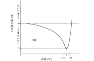
G''=(σ/γ)sinδ ・・・(3)
によりG'及びG''(単位:Pa)を求める。G'はポリエチレン系樹脂の硬さの指標であり、G''はポリエチレン系樹脂の粘性の指標である。図1に示すようにlogω−log G'曲線及びlogω−log G''曲線を作成し、これらの曲線の交点における角周波数をω0とする。
The stress σ is detected by applying strain γ to the sample while changing ω under the above conditions, and the following formula is obtained from γ, σ and the phase difference δ between the two.
G '= (σ / γ) cosδ (2)
G ″ = (σ / γ) sinδ (3)
To obtain G ′ and G ″ (unit: Pa). G ′ is an index of the hardness of the polyethylene resin, and G ″ is an index of the viscosity of the polyethylene resin. As shown in FIG. 1, a log ω-log G ′ curve and a log ω-log G ″ curve are created, and the angular frequency at the intersection of these curves is ω 0 .
パラメータω0は、以下の特性のうちの少なくとも一種が影響しても良い:重量平均分子量(Mw)、分子量分布、分岐度、分岐鎖の分子量、分岐点の分布、分子間の絡み合い度、絡み合い点間の分子量等。ポリエチレン(単独重合体又はエチレン・α-オレフィン共重合体)が直鎖状でかつ対数正規な分子量分布を有する場合、Mwが大きいほどω0は小さい。またポリエチレン(単独重合体又はエチレン・α-オレフィン共重合体)が長い分岐鎖を有すると、ω0は比較的小さい傾向がある。ω0が0.01 rad/sec未満だと、例えば十分な突刺強度を有するポリオレフィン微多孔膜の製造が困難であることがある。 The parameter ω 0 may be affected by at least one of the following characteristics: weight average molecular weight (Mw), molecular weight distribution, degree of branching, molecular weight of branched chain, distribution of branch points, degree of entanglement between molecules, entanglement Molecular weight between points. When polyethylene (homopolymer or ethylene / α-olefin copolymer) is linear and has a log-normal molecular weight distribution, ω 0 is smaller as Mw is larger. When polyethylene (homopolymer or ethylene / α-olefin copolymer) has a long branched chain, ω 0 tends to be relatively small. When ω 0 is less than 0.01 rad / sec, for example, it may be difficult to produce a polyolefin microporous film having sufficient puncture strength.
適切な範囲のω0を有するUHMWPE及び第二のポリエチレンは、例えば、公知の方法、好ましくはチーグラーナッタ触媒により製造することができる。 UHMWPE and second polyethylene having a suitable range of ω 0 can be produced, for example, by known methods, preferably by Ziegler-Natta catalysts.
(b) 分子量分布Mw/Mn
Mw/Mnは分子量分布の尺度であり、この値が大きいほど分子量分布の幅は大きい。分子量分布の選択は限定的ではない。例えば、Mw/Mnは、約5〜約300の範囲、約5〜約100の範囲、又は約5〜約30の範囲で良い。限定的ではないが、ポリエチレン系樹脂のMw/Mnが約5未満だと、比較的高い分子量のポリエチレンの量が多く、その樹脂から調製するポリオレフィン溶液を押し出すのが困難であることがある。またMw/Mnが約300超だと、樹脂が比較的低い分子量のポリエチレンを多量に含むので、十分な強度を有するポリオレフィン微多孔膜を製造するのが困難であることがある。
(b) Molecular weight distribution Mw / Mn
Mw / Mn is a measure of molecular weight distribution. The larger this value, the wider the molecular weight distribution. The choice of molecular weight distribution is not limited. For example, Mw / Mn can range from about 5 to about 300, from about 5 to about 100, or from about 5 to about 30. Although not limited, if the Mw / Mn of the polyethylene-based resin is less than about 5, the amount of polyethylene having a relatively high molecular weight is large, and it may be difficult to extrude a polyolefin solution prepared from the resin. If Mw / Mn is more than about 300, the resin contains a large amount of polyethylene having a relatively low molecular weight, and it may be difficult to produce a polyolefin microporous membrane having sufficient strength.
多段重合により、所望のMw/Mn比を有するポリエチレン系樹脂が得られる。例えば、一段目で比較的高い分子量のポリマー成分を生成し、二段目で比較的低い分子量のポリマー成分を生成する二段重合を用いることができる。必須ではないが、例えば第一のポリエチレン系樹脂がUHMWPEからなる場合、この方法を用いることができる。ポリエチレン系樹脂がUHMWPE及び第二のポリエチレンからなる場合、ポリエチレン系樹脂の所望のMw/Mn比は、第一及び第二のポリエチレンの分子量及び混合割合を選択することにより、調整することができる。 By the multistage polymerization, a polyethylene resin having a desired Mw / Mn ratio can be obtained. For example, it is possible to use a two-stage polymerization in which a polymer component having a relatively high molecular weight is produced in the first stage and a polymer component having a relatively low molecular weight is produced in the second stage. Although not essential, for example, this method can be used when the first polyethylene resin is made of UHMWPE. When the polyethylene resin is composed of UHMWPE and the second polyethylene, the desired Mw / Mn ratio of the polyethylene resin can be adjusted by selecting the molecular weight and mixing ratio of the first and second polyethylenes.
(B) 第二のポリオレフィン系樹脂
ポリエチレン系樹脂に加えて、ポリオレフィン溶液を調製するために、少なくとも第二のポリオレフィン(第二のポリオレフィン系樹脂)を用いることができる。従って、一実施態様において、ポリオレフィン溶液は、第二のポリオレフィンを含む。一実施態様において、第二のポリオレフィン(樹脂の形態)を、第一のポリオレフィン系樹脂に混合してポリオレフィン組成物を調製し、ポリオレフィン組成物をプロセス溶剤に混合してポリオレフィン溶液を調製するが、これに限定されない。その代わりに、複数種の樹脂の少なくとも一部を、順に又は同時にプロセス溶剤に混合してポリオレフィン溶液を調製しても良い。第二のポリオレフィンは、例えば以下のポリオレフィンのうちの少なくとも一種の樹脂で良い:ポリプロピレン、ポリブテン-1、ポリペンテン-1、ポリ-4-メチルペンテン-1、ポリヘキセン-1、ポリオクテン-1、ポリ酢酸ビニル、ポリメタクリル酸メチル、ポリスチレン及びエチレン・α-オレフィン共重合体。第二のポリオレフィン系樹脂は、単独重合体、第二のポリオレフィンとその他のα-オレフィンとの共重合体、又はこれらの両方を含んで良い。
(B) Second polyolefin resin In addition to the polyethylene resin, at least a second polyolefin (second polyolefin resin) can be used to prepare a polyolefin solution. Accordingly, in one embodiment, the polyolefin solution includes a second polyolefin. In one embodiment, a second polyolefin (in the form of a resin) is mixed with a first polyolefin-based resin to prepare a polyolefin composition, and the polyolefin composition is mixed with a process solvent to prepare a polyolefin solution. It is not limited to this. Instead, a polyolefin solution may be prepared by mixing at least a part of a plurality of types of resins with a process solvent in order or simultaneously. The second polyolefin may be, for example, at least one resin of the following polyolefins: polypropylene, polybutene-1, polypentene-1, poly-4-methylpentene-1, polyhexene-1, polyoctene-1, polyvinyl acetate , Polymethyl methacrylate, polystyrene, and ethylene / α-olefin copolymer. The second polyolefin-based resin may include a homopolymer, a copolymer of the second polyolefin and other α-olefin, or both.
第二のポリオレフィンを用いる一実施態様において、第二のポリオレフィンは、例えば約1×10⁴〜約4×10⁶の範囲のMwを有して良い。第二のポリオレフィンに加えて、又は第二のポリオレフィン以外に、ポリオレフィン組成物は、例えば約1×10³〜約1×10⁴の範囲のMwを有するポリエチレンワックスをさらに含んでも良い。これらの種は、望まれるポリオレフィン微多孔膜の特性(例えばメルトダウン、シャットダウン等)を大きく低下させない範囲で添加すべきである。 In one embodiment using a second polyolefin, the second polyolefin may have a Mw in the range of, for example, from about 1 × 10 4 to about 4 × 10 6 . In addition to or in addition to the second polyolefin, the polyolefin composition may further include a polyethylene wax having a Mw in the range of, for example, about 1 × 10 3 to about 1 × 10 4 . These species should be added to the extent that they do not significantly degrade the desired polyolefin microporous membrane properties (eg, meltdown, shutdown, etc.).
第二のポリオレフィンがポリプロピレンの場合、ポリプロピレンは、以下の特性のうちの一種以上を任意で有しても良い:(i) ポリプロピレンは、約1×10⁴〜約4×10⁶の範囲、又は約3×10⁵〜約3×10⁶の範囲のMwを有する;(ii) ポリプロピレンは、約1.01〜約100の範囲、又は約1.1〜約50の範囲のMw/Mnを有する;(iii) ポリプロピレンの立体規則性はアイソタクチックである;(iv) ポリプロピレンは、約90 Joules/g以上の融解熱を有する;(v) ポリプロピレンは、約160℃以上の融解ピーク(第二の融解)を有する;(vi) ポリプロピレンは、約230℃の温度及び歪み速度25 sec-1において約15以上のトルートン比を有する;(vii) ポリプロピレンは、230℃の温度及び歪み速度25 sec-1において約50,000 Pa・sec以上の伸長粘度を有する。 When the second polyolefin is polypropylene, the polypropylene may optionally have one or more of the following properties: (i) the polypropylene ranges from about 1 × 10 4 to about 4 × 10 6 , or Having a Mw in the range of about 3 × 10 5 to about 3 × 10 6 ; (ii) the polypropylene has a Mw / Mn in the range of about 1.01 to about 100, or in the range of about 1.1 to about 50; (iii) The stereoregularity of polypropylene is isotactic; (iv) polypropylene has a heat of fusion of about 90 Joules / g or more; (v) polypropylene has a melting peak (second melting) of about 160 ° C. or more. (Vi) polypropylene has a Troughton ratio of about 15 or higher at a temperature of about 230 ° C. and a strain rate of 25 sec −1 ; (vii) polypropylene has a temperature of about 50,000 at a temperature of 230 ° C. and a strain rate of 25 sec −1 . Has an extensional viscosity of Pa · sec or more.
[2] ポリオレフィン微多孔膜の製造方法
ポリオレフィン微多孔膜の製造に使用する材料の組成及び特性について述べたが、以下かかる膜の製造方法について詳細に説明する。これらに限定的されないが、第一の製造方法及び第二の製造方法の二つの製造方法について説明する。
[2] Manufacturing Method of Polyolefin Microporous Membrane The composition and characteristics of the material used for manufacturing the polyolefin microporous membrane have been described. The manufacturing method of such a membrane will be described in detail below. Although not limited to these, two manufacturing methods, the first manufacturing method and the second manufacturing method, will be described.
(A) 第一の製造方法
一実施態様において、本発明は、ポリオレフィン微多孔膜を製造する第一の方法に関する。第一の方法は、(1) ポリオレフィン組成物及びプロセス溶剤を混合してポリオレフィン溶液を調製し、(2) ポリオレフィン溶液をダイより押し出して押出し成形体を形成し、押出し成形体を冷却して冷却押出し成形体を形成し、(3) 冷却押出し成形体を延伸して延伸シートを形成し、(4) 延伸シートから成膜用溶剤を除去して溶剤除去シートを形成し、任意で溶剤除去シートを乾燥し、(5) さらに溶剤除去シートを延伸して再延伸シートを形成し、再延伸シートを熱固定処理又は熱緩和処理する工程を有する。
(A) First Production Method In one embodiment, the present invention relates to a first method for producing a polyolefin microporous membrane. The first method consists of (1) preparing a polyolefin solution by mixing the polyolefin composition and process solvent, and (2) extruding the polyolefin solution from a die to form an extruded product, and cooling and cooling the extruded product. Forming an extruded molded body, (3) stretching the cooled extruded molded body to form a stretched sheet, (4) removing the film-forming solvent from the stretched sheet to form a solvent-removed sheet, and optionally a solvent-removed sheet (5) Furthermore, the solvent removal sheet is stretched to form a restretched sheet, and the restretched sheet is heat-set or heat relaxed.
工程(5)の後、必要に応じて、熱緩和処理又は第二の熱緩和処理工程[工程(6)]、電離放射による架橋処理工程[工程(7)]、親水化処理工程[工程(8)]、表面被覆処理工程[工程(9)]等の一種以上の任意の工程を行っても良い。任意の工程の順番は限定的ではない。 After step (5), if necessary, thermal relaxation treatment or second thermal relaxation treatment step [step (6)], cross-linking treatment step by ionizing radiation [step (7)], hydrophilic treatment step [step ( 8)], surface coating treatment step [step (9)], etc., one or more arbitrary steps may be performed. The order of the optional steps is not limited.
(1) ポリオレフィン溶液の調製
上記のようなポリオレフィン系樹脂と、少なくとも一種のプロセス溶剤(希釈剤又は成膜用溶剤ともよぶ)とを混合、例えば溶融混合し、ポリオレフィン溶液を調製する。樹脂及び溶剤は、連続して、同時に、又はこれらを組合せて添加することができる。ポリオレフィン溶液は、まず少なくとも一部の樹脂を混合してポリオレフィン組成物を調製し、次いでポリオレフィン組成物と少なくとも一種の成膜用溶剤とを混合することにより(さらに任意で、残りの樹脂及び/又は追加する樹脂を混合することにより)調製しても良い。
(1) Preparation of polyolefin solution The polyolefin resin as described above and at least one process solvent (also referred to as a diluent or a film-forming solvent) are mixed, for example, melt-mixed to prepare a polyolefin solution. The resin and solvent can be added sequentially, simultaneously or in combination. The polyolefin solution is prepared by first mixing at least a portion of a resin to prepare a polyolefin composition, and then mixing the polyolefin composition and at least one film-forming solvent (and optionally, the remaining resin and / or It may be prepared by mixing additional resins).
上記のようなポリオレフィン系樹脂を含むポリオレフィン組成物を、適当な成膜用溶剤とともに、例えばドライブレンド又は溶融混練により混合して、ポリオレフィン溶液を調製しても良い。任意で、ポリオレフィン溶液に、酸化防止剤、微粉珪酸(孔形成剤)等のような一種以上の添加剤を添加しても良い。これらは、望まれるポリオレフィン微多孔膜の特性を低下させない範囲で使用する。 A polyolefin solution containing the polyolefin resin as described above may be mixed with an appropriate film forming solvent by, for example, dry blending or melt kneading to prepare a polyolefin solution. Optionally, one or more additives such as antioxidants, finely divided silicic acid (pore forming agent), etc. may be added to the polyolefin solution. These are used as long as the desired properties of the microporous polyolefin membrane are not deteriorated.
成膜用溶剤は室温で液体であるのが好ましい。いかなる理論又はモデルにも拘束されることは望まないが、液体溶剤の使用により、比較的高い延伸倍率での冷却押出し成形体の延伸を可能にする第一のポリオレフィン溶液が得られると考えられる。一実施態様において、プロセス溶剤としては、ノナン、デカン、デカリン、パラキシレン、ウンデカン、ドデカン、流動パラフィン等の脂肪族、環式脂肪族又は芳香族の炭化水素、及び沸点がこれらに対応する鉱油留分、並びにジブチルフタレート、ジオクチルフタレート等の室温では液状のフタル酸エステルからなる群から選ばれた少なくとも一種で良い。一実施態様において、液体溶剤の含有量が安定な冷却押出し成形体を得るために、単独で又は他の溶剤と組合せて、流動パラフィンのような不揮発性の液体溶剤を用いることができる。任意で、溶融混練状態ではポリオレフィンと混和するが室温では固体の溶剤を、単独で又は液体溶剤と組合せて使用しても良い。このような固体溶剤として、ステアリルアルコール、セリルアルコール、パラフィンワックス等が挙げられる。限定的ではないが、溶液が液体溶剤を含まないと、冷却押出し成形体又は得られる膜を均一に延伸するのが困難であることがある。 The film-forming solvent is preferably a liquid at room temperature. While not wishing to be bound by any theory or model, it is believed that the use of a liquid solvent provides a first polyolefin solution that allows stretching of the cooled extrudate at relatively high draw ratios. In one embodiment, the process solvent includes aliphatic, cycloaliphatic or aromatic hydrocarbons such as nonane, decane, decalin, paraxylene, undecane, dodecane, liquid paraffin, and mineral oil fractions with boiling points corresponding thereto. And at least one selected from the group consisting of liquid phthalates such as dibutyl phthalate and dioctyl phthalate at room temperature. In one embodiment, a non-volatile liquid solvent such as liquid paraffin can be used alone or in combination with other solvents in order to obtain a cooled extrudate with a stable liquid solvent content. Optionally, a solvent that is miscible with the polyolefin in the melt-kneaded state but solid at room temperature may be used alone or in combination with a liquid solvent. Examples of such a solid solvent include stearyl alcohol, seryl alcohol, and paraffin wax. Without limitation, if the solution does not contain a liquid solvent, it may be difficult to uniformly stretch the cooled extrudate or the resulting film.
プロセス溶剤の粘度は限定的なパラメータではない。例えば、液体溶剤の粘度は25℃で測定したときに約30 cSt〜約500 cSt、又は約30 cSt〜約200 cStで良い。限定的なパラメータではないが、25℃における粘度が約30 cSt未満では、ポリオレフィン溶液の発泡を避けるのが困難なことがあり、これは混練を困難にする恐れがある。一方約500 cSt超では、ポリオレフィン微多孔膜から液体溶剤を除去するのが困難なことがある。 The viscosity of the process solvent is not a limiting parameter. For example, the viscosity of the liquid solvent may be from about 30 cSt to about 500 cSt, or from about 30 cSt to about 200 cSt when measured at 25 ° C. Although not a limiting parameter, if the viscosity at 25 ° C. is less than about 30 cSt, it may be difficult to avoid foaming of the polyolefin solution, which may make kneading difficult. On the other hand, if it exceeds about 500 cSt, it may be difficult to remove the liquid solvent from the microporous polyolefin membrane.
一実施態様において、ポリオレフィン組成物を調製するのに使用した樹脂等は、例えば二軸押出機又はミキサー中で溶融混練する。ポリオレフィン組成物を調製するために、例えば、二軸押出機のような公知の押出機(又はミキサー又はミキサー・押出機)を樹脂等の混合に使用することができる。プロセス溶媒は、ポリオレフィン組成物(又はポリオレフィン組成物の調製に用いた樹脂)に、プロセスの任意の時点において添加して良い。例えば、ポリオレフィン組成物及びプロセス溶媒を溶融混練する実施態様において、(i) 溶融混練前、(ii) ポリオレフィン組成物の溶融混練の途中、又は(iii) 溶融混練後のいずれかにおいて、例えば第二の押出機中、又はポリオレフィン組成物の溶融混練に使用した押出機ゾーンの下流に位置する押出機ゾーン中において、溶融混練したポリオレフィン組成物又は部分的に溶融混練したポリオレフィン組成物にプロセス溶媒を添加することにより、溶媒をポリオレフィン組成物(又はその各構成要素)に添加して良い。 In one embodiment, the resin used to prepare the polyolefin composition is melt kneaded, for example, in a twin screw extruder or mixer. In order to prepare the polyolefin composition, for example, a known extruder (or a mixer or a mixer / extruder) such as a twin screw extruder can be used for mixing the resin and the like. The process solvent may be added to the polyolefin composition (or the resin used to prepare the polyolefin composition) at any point in the process. For example, in an embodiment in which the polyolefin composition and the process solvent are melt-kneaded, (i) before the melt-kneading, (ii) in the middle of the melt-kneading of the polyolefin composition, or (iii) after the melt-kneading, for example, the second Process solvent is added to the melt-kneaded polyolefin composition or partially melt-kneaded polyolefin composition in the extruder or in the extruder zone located downstream of the extruder zone used for melt-kneading the polyolefin composition By doing so, a solvent may be added to the polyolefin composition (or each of its constituents).
溶融混練する場合、溶融混練温度は限定的ではない。例えば、溶融混練中のポリオレフィン溶液の温度(溶融混練温度)は、例えばポリエチレン系樹脂の融点Tmより約10℃高い温度〜Tmより約120℃高い温度の範囲とすることができる。簡略化のために、この範囲をTm + 10℃〜Tm + 120℃と表す。一実施態様において、ポリエチレン系樹脂が約130℃〜約140℃の融点を有する場合、溶融混練温度は約140℃〜約250℃の範囲又は約170℃〜約240℃の範囲で良い。 In the case of melt kneading, the melt kneading temperature is not limited. For example, the temperature of the polyolefin solution during melt-kneading (melt-kneading temperature) can be, for example, in the range of about 10 ° C. higher than the melting point Tm of the polyethylene resin to about 120 ° C. higher than Tm. For simplicity, this range is expressed as Tm + 10 ° C. to Tm + 120 ° C. In one embodiment, when the polyethylene-based resin has a melting point of about 130 ° C to about 140 ° C, the melt kneading temperature can be in the range of about 140 ° C to about 250 ° C or in the range of about 170 ° C to about 240 ° C.
二軸押出機のような押出機を溶融混練に用いる場合、スクリュのパラメータは限定的ではない。例えばスクリュは、二軸押出機のスクリュの長さ(L)と直径(D)の比(L/D)で特徴付けられる。L/Dは、例えば約20〜約100の範囲、又は約35〜約70の範囲で良い。このパラメータは限定的ではないが、L/Dを約20未満にすると、溶融混練が困難になることがある。L/Dを約100超にすると、二軸押出機中のポリオレフィン溶液の過剰な滞留時間(これは望ましくない分子量の低下をもたらす可能性がある)を避けるために、より速い押出速度を要する可能性がある。限定的なパラメータではないが、二軸押出機のシリンダ(又はボア)は、例えば約40〜約100 mmの範囲の内径を有して良い。 When an extruder such as a twin screw extruder is used for melt kneading, the screw parameters are not limited. For example, a screw is characterized by the ratio (L / D) of the screw length (L) to the diameter (D) of a twin screw extruder. L / D can be, for example, in the range of about 20 to about 100, or in the range of about 35 to about 70. This parameter is not limited, but if L / D is less than about 20, melt kneading may become difficult. L / D above about 100 may require higher extrusion speeds to avoid excessive residence time of the polyolefin solution in the twin screw extruder, which may lead to undesirable molecular weight reduction There is sex. Although not a limiting parameter, the cylinder (or bore) of the twin screw extruder may have an inner diameter in the range of about 40 to about 100 mm, for example.
ポリオレフィン溶液中のポリオレフィン組成物の含有量は制限されない。一実施態様において、ポリオレフィン溶液の重量基準で、ポリオレフィン溶液中のポリオレフィン組成物の含有量は約1重量%〜約75重量%の範囲でよく、例えば約20重量%〜約70重量%の範囲でも良い。ポリオレフィン溶液中のポリオレフィン組成物の含有量は制限されないが、その含有量が約1重量%未満では、許容できる効率的な速度でのポリオレフィン微多孔膜の製造が困難であることがある。その含有量が約1重量%未満では、押し出し中におけるダイ出口でのスウェルやネックインを防止するのが困難なことがあり、そのため冷却押出し成形体を成形し支持するのが困難なことがある。一方約75重量%を超えると、冷却押出し成形体の成形が困難になることがある。 The content of the polyolefin composition in the polyolefin solution is not limited. In one embodiment, based on the weight of the polyolefin solution, the content of the polyolefin composition in the polyolefin solution may range from about 1 wt% to about 75 wt%, such as from about 20 wt% to about 70 wt%. good. The content of the polyolefin composition in the polyolefin solution is not limited, but if the content is less than about 1% by weight, it may be difficult to produce a microporous polyolefin membrane at an acceptable and efficient rate. If the content is less than about 1% by weight, it may be difficult to prevent swell and neck-in at the die exit during extrusion, and thus it may be difficult to form and support a cooled extruded product. . On the other hand, if it exceeds about 75% by weight, it may be difficult to form a cooled extruded product.
(2) 押出及び押出し成形体の冷却
一実施態様において、少なくとも一部のポリオレフィン溶液をダイから押し出し、押出し成形体を形成する。例えばポリオレフィン溶液を押し出し、第一の押出機からダイに直接導けば良い。別の実施態様において、別に付加した押出機(第二の、第三の等)を用いても良い。別の押出機は、第一の押出機に直列及び/又は並列に接続すれば良い。第一の押出機からの生成物は、冷却し、ペレット化しても良い。次いで、ペレットを、例えば溶融混練し、第二の押出機及びダイから押し出し、ゲル状成形体又はシートを形成することができる。ダイの形状は限定的ではない。例えばダイは、長方形の口金を有するシート用ダイ、二重円筒状の中空状ダイ、ホローダイ、インフレーションダイ等で良い。ダイのギャップは限定的ではない。シート用ダイの場合、一般的にダイのギャップは約0.1 mm〜約5mmである。押出中のポリオレフィン溶液の温度(すなわち押出温度)は限定的ではないが、一般的に約140℃〜約250℃の範囲である。押し出し速度は限定的ではないが、一般的に約0.2 m/分〜約15 m/分の範囲である。
(2) Extrusion and cooling of the extruded product In one embodiment, at least a portion of the polyolefin solution is extruded from a die to form an extruded product. For example, the polyolefin solution may be extruded and guided directly from the first extruder to the die. In another embodiment, a separately added extruder (second, third, etc.) may be used. Another extruder may be connected in series and / or in parallel to the first extruder. The product from the first extruder may be cooled and pelletized. The pellets can then be melt kneaded, for example, and extruded from a second extruder and die to form a gel shaped body or sheet. The shape of the die is not limited. For example, the die may be a sheet die having a rectangular base, a double cylindrical hollow die, a hollow die, an inflation die, or the like. The die gap is not critical. For sheet dies, the die gap is typically between about 0.1 mm and about 5 mm. The temperature of the polyolefin solution during extrusion (i.e., the extrusion temperature) is not critical, but generally ranges from about 140 ° C to about 250 ° C. The extrusion rate is not critical, but generally ranges from about 0.2 m / min to about 15 m / min.
一実施態様において、押出し成形体を冷却し、冷却押出し成形体を形成する。冷却は、押出し成形体がゲル化温度(すなわち、押出シートがゲル化を開始する温度)以下に到達するまでは約50℃/分以上の冷却速度で行えば良い。一実施態様において、押出し成形体を約25℃以下まで冷却する。いかなる理論又はモデルにも拘束されることは望まないが、冷却により、成膜用溶剤によって分離されたポリオレフィン領域からなるミクロ相が形成されると考えられる。一般に冷却速度が遅いと得られる冷却押出し成形体の高次構造が粗くなり、それを形成する擬似細胞単位も大きくなると考えられる。一方冷却速度が速いと密な細胞単位となる。冷却速度が50℃/分未満では、おそらく膜の結晶化度の上昇により、冷却押出し成形体の延伸(工程(4))が困難になることがある。冷却方法は限定的ではない。冷却方法として、例えば冷風、冷却水等の冷却媒体に押出し成形体を直接接触させる方法、冷媒で冷却したロールにゲル状シートを接触させる方法等を用いることができる。 In one embodiment, the extruded body is cooled to form a cooled extruded body. Cooling may be performed at a cooling rate of about 50 ° C./min or more until the extruded product reaches a gelling temperature (that is, a temperature at which the extruded sheet starts to gel) or less. In one embodiment, the extrudate is cooled to about 25 ° C. or less. While not wishing to be bound by any theory or model, it is believed that cooling forms a microphase consisting of polyolefin regions separated by a film-forming solvent. Generally, when the cooling rate is slow, the higher-order structure of the resulting cooled extruded product becomes rough, and the pseudo-cell unit forming it is considered to be larger. On the other hand, when the cooling rate is high, the cell unit becomes dense. If the cooling rate is less than 50 ° C./min, stretching of the cooled extruded product (step (4)) may become difficult, possibly due to an increase in the crystallinity of the film. The cooling method is not limited. As a cooling method, for example, a method in which an extruded product is brought into direct contact with a cooling medium such as cold air or cooling water, a method in which a gel-like sheet is brought into contact with a roll cooled with a refrigerant, or the like can be used.
(3) 延伸
一実施態様において、冷却押出し成形体を少なくとも一軸方向に延伸し、延伸シートを形成する。いかなる理論又はモデルにも拘束されることは望まないが、冷却押出し成形体は、成膜用溶剤を含むと一層均一に延伸できると考えられる。延伸方法及び延伸倍率はいずれも特に制限されない。例えば延伸方法は、(任意での加熱を伴い又は伴わずに)予め決めた倍率に冷却押出し成形体を延伸可能ないかなる方法でも良い。一実施態様において、延伸はテンター延伸、ロール延伸又はインフレーション延伸(例えば空気を用いる)の少なくとも一種により行う。限定的ではないが、延伸は一軸又は二軸で行うことができる。一軸延伸は、一方向、例えば機械(すなわち長手)方向又は横手方向への冷却押出し成形体の延伸に関わる。二軸延伸は、二方向、例えば機械方向(MD)及び横手方向(TD)の両方への冷却押出し成形体の延伸に関わる。ここで機械方向は、フィルム(この場合冷却押出し成形体)面において、フィルム形成時の移動方向にほぼ沿って配向した方向であり、すなわち製造中のフィルムの長軸方向である。横手方向は、フィルム面において、機械方向とフィルムの厚さ方向にほぼ平行な第三の軸との両方に対して直角に延びる方向である。
(3) Stretching In one embodiment, the cooled extruded product is stretched at least in a uniaxial direction to form a stretched sheet. Although not wishing to be bound by any theory or model, it is believed that the cooled extruded body can be stretched more uniformly when it contains a film-forming solvent. Neither the stretching method nor the stretching ratio is particularly limited. For example, the stretching method may be any method that can stretch the cooled extrusion-molded body at a predetermined magnification (with or without optional heating). In one embodiment, the stretching is performed by at least one of tenter stretching, roll stretching, or inflation stretching (eg, using air). Without limitation, stretching can be done uniaxially or biaxially. Uniaxial stretching involves stretching of the cooled extruded body in one direction, for example, the machine (ie, longitudinal) direction or the transverse direction. Biaxial stretching involves stretching of a cooled extruded body in two directions, for example, both the machine direction (MD) and the transverse direction (TD). Here, the machine direction is a direction oriented substantially along the moving direction during film formation on the surface of the film (in this case, the cooled extruded product), that is, the major axis direction of the film being manufactured. The transverse direction is a direction extending perpendicular to both the machine direction and a third axis substantially parallel to the thickness direction of the film on the film surface.
一実施態様において、二軸延伸を用いる。二軸延伸(二軸配向ともよぶ)の場合、同時二軸延伸、一軸及び他の軸に沿って行う逐次延伸及び多段延伸(例えば同時二軸延伸及び逐次延伸の組合せ)のいずれでも良い。一実施態様において、同時二軸延伸を用いる。 In one embodiment, biaxial stretching is used. In the case of biaxial stretching (also referred to as biaxial orientation), any of simultaneous biaxial stretching, sequential stretching performed along one axis and another axis, and multistage stretching (for example, a combination of simultaneous biaxial stretching and sequential stretching) may be used. In one embodiment, simultaneous biaxial stretching is used.
延伸倍率は限定的ではない。一実施態様において、一軸延伸の場合、直線的な延伸の倍率は約2倍以上か、約3〜約30倍で良い。一実施態様において、二軸延伸の場合、直線的な延伸の倍率は、例えば少なくとも2方向、例えば機械方向及び横手方向において、約3倍以上で良い。別の実施態様において、二軸延伸における面積倍率は、少なくとも約9倍か、少なくとも約16倍か、少なくとも約25倍で良い。限定的ではないが、面積倍率を少なくとも約9倍とすると、比較的高い突刺強度を有するポリオレフィン微多孔膜の製造が容易となる。面積倍率を400倍超とすると、冷却押出し成形体の裂けを伴わないで延伸装置を操作するのが困難になることがある。 The draw ratio is not limited. In one embodiment, in the case of uniaxial stretching, the linear stretching ratio may be about 2 times or more, or about 3 to about 30 times. In one embodiment, in the case of biaxial stretching, the linear stretching ratio may be, for example, about 3 times or more in at least two directions, such as the machine direction and the transverse direction. In another embodiment, the area magnification in biaxial stretching may be at least about 9 times, at least about 16 times, or at least about 25 times. Although not limited, when the area magnification is at least about 9, production of a polyolefin microporous membrane having a relatively high puncture strength is facilitated. If the area magnification is more than 400 times, it may be difficult to operate the stretching apparatus without tearing the cooled extruded product.
延伸温度は、ゲル状シートのポリエチレン系樹脂が超高分子量ポリエチレン、それ以外のポリエチレン、又はポリエチレン組成物のいずれの場合であっても、118℃以上とし、118℃〜ポリエチレン系樹脂の融点Tm+10℃にするのが好ましく、118℃以上融点Tm未満の範囲にするのがより好ましい。延伸温度が118℃未満では、耐熱収縮性(105℃)や耐溶融収縮性が低い。延伸温度が融点Tm+10℃を超えるとポリエチレン系樹脂が溶融し、延伸による分子鎖の配向ができない。 The stretching temperature is 118 ° C. or higher, regardless of whether the polyethylene resin of the gel sheet is ultrahigh molecular weight polyethylene, other polyethylene, or a polyethylene composition, and the melting point of the polyethylene resin Tm + 10 ° C. Preferably, the temperature is in the range of 118 ° C. or higher and lower than the melting point Tm. When the stretching temperature is less than 118 ° C, the heat shrinkage resistance (105 ° C) and the melt shrinkage resistance are low. When the stretching temperature exceeds the melting point Tm + 10 ° C., the polyethylene resin is melted and the molecular chain cannot be oriented by stretching.
UHMWPE、第二のポリエチレン、及びポリエチレン組成物(UHMWPE及び第二のポリエチレンからなる)は一般的に約130℃〜約140℃のTmを有し、約90℃〜約100℃のTcdを有する。TcdはASTM D4065による動的粘弾性の温度特性から求めることができる。 The UHMWPE, the second polyethylene, and the polyethylene composition (consisting of UHMWPE and the second polyethylene) generally have a Tm of about 130 ° C to about 140 ° C and a Tcd of about 90 ° C to about 100 ° C. Tcd can be determined from the temperature characteristics of dynamic viscoelasticity according to ASTM D4065.
いかなる理論又はモデルにも拘束されることは望まないが、以上のような延伸によりポリエチレン結晶ラメラ間の開裂が起こり、ポリエチレン相が微細化し、多数のフィブリルが形成されると考えられる。その結果、延伸により、比較的大きな細孔径を有し、比較的高い機械的強度を有するポリオレフィン微多孔膜を容易に製造できる。このようなポリオレフィン微多孔膜は、電池用セパレータ用途に特に適していると考えられる。 Although not wishing to be bound by any theory or model, it is considered that the above-described stretching causes cleavage between polyethylene crystal lamellae, and the polyethylene phase is refined to form a large number of fibrils. As a result, a polyolefin microporous film having a relatively large pore diameter and a relatively high mechanical strength can be easily produced by stretching. Such a polyolefin microporous membrane is considered to be particularly suitable for battery separator applications.
任意で、延伸は、厚さ方向(すなわち、ポリオレフィン微多孔膜の表面にほぼ直角な方向)に温度分布が存在する条件で行っても良い。この場合、機械的強度が改善されたポリオレフィン微多孔膜の製造が容易となる。その方法の詳細は日本国特許第3347854号に記載されている。 Optionally, the stretching may be performed under the condition that a temperature distribution exists in the thickness direction (that is, a direction substantially perpendicular to the surface of the polyolefin microporous membrane). In this case, it becomes easy to produce a polyolefin microporous film having improved mechanical strength. Details of this method are described in Japanese Patent No. 3347854.
(4) プロセス溶剤の除去
一実施態様において、溶剤を除去したシートを形成するために、延伸シートからプロセス溶剤の少なくとも一部を除去(置換)する。プロセス溶剤を除去(洗浄又は置換)するために、第二の溶媒(置換用又は洗浄用溶媒ともよぶ)を用いても良い。いかなる理論又はモデルにも拘束されることは望まないが、延伸シート中に生成したポリオレフィン相は、プロセス溶剤相から分離されているので、プロセス溶剤を除去すると、微細な三次元網目構造を形成するフィブリルからなり、三次元的に不規則に連通する孔を有する多孔質の膜が得られると考えられる。
(4) Removal of process solvent In one embodiment, at least a portion of the process solvent is removed (replaced) from the stretched sheet to form a sheet from which the solvent has been removed. In order to remove (clean or replace) the process solvent, a second solvent (also referred to as a replacement or cleaning solvent) may be used. Although not wishing to be bound by any theory or model, the polyolefin phase produced in the stretched sheet is separated from the process solvent phase, so forming a fine three-dimensional network structure when the process solvent is removed. It is considered that a porous film made of fibrils and having pores communicating irregularly in three dimensions can be obtained.
プロセス溶剤を溶解又は置換することができる限り、洗浄溶媒は制限されない。適した洗浄溶媒として、例えばペンタン、ヘキサン、ヘプタン等の飽和炭化水素、塩化メチレン、四塩化炭素等の塩素化炭化水素、ジエチルエーテル、ジオキサン等のエーテル類、メチルエチルケトン等のケトン類、三フッ化エタン,C6F14,C7F16等の鎖状フルオロカーボン、C5H3F7等の環状ハイドロフルオロカーボン、C4F9OCH3,C4F9OC2H5等のハイドロフルオロエーテル、C4F9OCF3,C4F9OC2F5等のパーフルオロエーテル等の易揮発性溶媒の少なくとも一種が挙げられる。 The cleaning solvent is not limited as long as the process solvent can be dissolved or replaced. Suitable washing solvents include, for example, saturated hydrocarbons such as pentane, hexane and heptane, chlorinated hydrocarbons such as methylene chloride and carbon tetrachloride, ethers such as diethyl ether and dioxane, ketones such as methyl ethyl ketone, and trifluoroethane Chain fluorocarbons such as C 6 F 14 and C 7 F 16 , cyclic hydrofluorocarbons such as C 5 H 3 F 7, hydrofluoroethers such as C 4 F 9 OCH 3 and C 4 F 9 OC 2 H 5 , C Examples thereof include at least one kind of readily volatile solvent such as perfluoroether such as 4 F 9 OCF 3 and C 4 F 9 OC 2 F 5 .
プロセス溶剤の除去方法は制限されず、公知の溶剤除去方法を含めて、溶剤の大部分を除去することができる限りいずれの方法でも用いることができる。例えば、延伸シートは、洗浄溶媒に浸漬する方法、洗浄溶媒をシャワーする方法、又はこれらの組合せにより洗浄することができる。洗浄溶媒の使用量は限定的ではないが、一般的にプロセス溶剤の除去に用いる方法に依存する。例えば、洗浄溶媒は、延伸シートの重量を基準として、約300〜約30,000重量部使用することができる。そうするのが一般に望ましいが、必ずしも延伸シートから全てのプロセス溶剤を除去する必要はない。溶剤除去工程後に、延伸シート中にかなりの量の溶剤が残留すると、所望の空孔率を有する膜の製造が困難になることがある。従って、一実施態様において、延伸シート中に残留するプロセス溶剤の量が、延伸シートの重量を基準として、約1重量%未満になるまで、延伸ゲル状シートからプロセス溶剤を除去する。任意で、溶剤除去シートは乾燥しても良い。 The method for removing the process solvent is not limited, and any method can be used as long as most of the solvent can be removed, including known solvent removal methods. For example, the stretched sheet can be cleaned by a method of immersing in a cleaning solvent, a method of showering a cleaning solvent, or a combination thereof. The amount of the cleaning solvent used is not limited, but generally depends on the method used to remove the process solvent. For example, the cleaning solvent can be used in an amount of about 300 to about 30,000 parts by weight based on the weight of the stretched sheet. While it is generally desirable to do so, it is not necessary to remove all process solvent from the stretched sheet. If a considerable amount of solvent remains in the stretched sheet after the solvent removal step, it may be difficult to produce a film having a desired porosity. Thus, in one embodiment, the process solvent is removed from the stretched gel sheet until the amount of process solvent remaining in the stretched sheet is less than about 1% by weight, based on the weight of the stretched sheet. Optionally, the solvent removal sheet may be dried.
乾燥する場合、乾燥シートを形成するために、溶剤除去シートは、洗浄溶媒(又はいずれかの揮発性種)の少なくとも一部を除去することができるいずれかの方法により、乾燥することができる。例えば、膜を、加熱乾燥法又は風乾法等により乾燥することができる。乾燥温度は限定的ではない。例えば、乾燥温度は上記Tcd以下、任意でTcd(ASTM D-4065)より5℃以上低くても良い。UHMWPE、第二のポリエチレン及びポリエチレン組成物は、約90℃〜約100℃の範囲の結晶分散温度を有する。乾燥は、ポリオレフィン微多孔膜を100重量%(乾燥重量)として、残存洗浄溶媒が5重量%以下になるまで行うのが好ましく、3重量%以下になるまで行うのがより好ましい。乾燥が不十分であると、後の熱処理でポリオレフィン微多孔膜の空孔率が低下し、透過性が悪化する。 When dried, the solvent removal sheet can be dried by any method that can remove at least a portion of the wash solvent (or any volatile species) to form a dry sheet. For example, the film can be dried by a heat drying method or an air drying method. The drying temperature is not critical. For example, the drying temperature may be Tcd or less, and optionally 5 ° C. or more lower than Tcd (ASTM D-4065). UHMWPE, the second polyethylene and the polyethylene composition have a crystal dispersion temperature in the range of about 90 ° C to about 100 ° C. Drying is preferably performed until the residual micro solvent is 100% by weight (dry weight) and the residual washing solvent is 5% by weight or less, and more preferably 3% by weight or less. If the drying is insufficient, the porosity of the polyolefin microporous membrane is lowered by the subsequent heat treatment, and the permeability is deteriorated.
(5) 再延伸
乾燥シートは、少なくとも一軸方向、すなわち少なくとも一側方にさらに延伸する(工程(3)の延伸と区別するために、再延伸又はドライ延伸とも呼ぶ)。延伸方法の選択は限定的ではなく、例えばテンタークリップを用いる機械延伸等の公知の延伸方法を用いることができる。
(5) Re-stretching The dried sheet is further stretched in at least one axial direction, that is, at least one side (also referred to as re-stretching or dry stretching in order to distinguish it from stretching in step (3)). The selection of the stretching method is not limited. For example, a known stretching method such as mechanical stretching using a tenter clip can be used.
限定的ではないが、延伸は一軸又は二軸で行うことができる。二軸延伸の場合、ほぼ直角方向(例えば機械方向及び横手方向)に同時に行うか、一方向及び他の方向に順に行うことができる。一実施態様において、同時二軸延伸を用いる。なお再延伸は通常延伸ゲル状シートから得られた長尺シート状の微多孔膜に対して行うので、再延伸におけるMD方向及びTD方向とゲル状シートの延伸におけるMD方向及びTD方向とは一致する。これは他の製造方法例でも同じである。 Without limitation, stretching can be done uniaxially or biaxially. In the case of biaxial stretching, it can be performed simultaneously in substantially perpendicular directions (for example, the machine direction and the transverse direction), or sequentially in one direction and the other direction. In one embodiment, simultaneous biaxial stretching is used. Since re-stretching is usually performed on a long sheet-like microporous membrane obtained from a stretched gel-like sheet, the MD direction and TD direction in re-stretching coincide with the MD direction and TD direction in stretching the gel-like sheet. To do. The same applies to other examples of the manufacturing method.
任意であるが、再延伸はシートを昇温した状態(再延伸温度)で行っても良い。再延伸の温度は、例えば約127℃以下、又はポリエチレン系樹脂の結晶分散温度Tcd〜127℃の範囲内である。 Although optional, re-stretching may be performed in a state where the sheet is heated (re-stretching temperature). The temperature of redrawing is, for example, about 127 ° C. or less, or a crystal dispersion temperature Tcd to 127 ° C. of the polyethylene resin.
再延伸温度が約127℃を超えると、比較的高い透過性及び比較的低い溶融直前の熱収縮率を有するポリオレフィン微多孔膜を製造するのが困難となることがある。一方再延伸温度がTcd未満では、ポリオレフィン微多孔膜のポリオレフィンを軟化するのが困難となることがあり、そのためドライ延伸中の破膜及び均一性の欠如を招くことがある。一実施態様において、再延伸の少なくとも一軸方向への倍率は約1.3〜約1.5倍の範囲にする。一軸延伸の場合、例えばシートの長手方向(機械方向)又は横手方向にほぼ平行な方向への倍率は約1.3〜約1.5倍で良い。例えば、溶剤除去シートは、再延伸前の再延伸方向の長さL1から、再延伸方向における最終的な長さL2まで、1.3L1≦L2≦1.5L1を満たすように、約127℃以下の膜温度でシートの少なくとも一方向に延伸することができる。
If the restretching temperature exceeds about 127 ° C., it may be difficult to produce a polyolefin microporous membrane having a relatively high permeability and a relatively low heat shrinkage just before melting. On the other hand, if the redrawing temperature is lower than Tcd, it may be difficult to soften the polyolefin of the polyolefin microporous membrane, and this may lead to film breakage and lack of uniformity during dry drawing. In one embodiment, the at least uniaxial magnification of redrawing ranges from about 1.3 to about 1.5 times. In the case of uniaxial stretching, for example, the magnification in the direction substantially parallel to the longitudinal direction (machine direction) or the transverse direction of the sheet may be about 1.3 to about 1.5 times. For example, the solvent-removable sheet is approximately about to satisfy 1.3L 1 ≦ L 2 ≦ 1.5L 1 from the length L 1 in the re-stretch direction before re-stretching to the final length L 2 in the re- stretch direction. The sheet can be stretched in at least one direction of the sheet at a film temperature of 127 ° C. or less.
二軸延伸の場合、倍率は長手及び横手方向の両方に約1.3倍〜約1.5倍の範囲とすれば良い。例えば長手及び横手方向における倍率は、それぞれ独立に選択することができ、互いに同じでも異なっても良い。一実施態様において、長手及び横手方向において同倍率で二軸延伸を行う。 In the case of biaxial stretching, the magnification may be in the range of about 1.3 times to about 1.5 times in both the longitudinal and transverse directions. For example, the magnifications in the longitudinal and transverse directions can be selected independently, and may be the same or different from each other. In one embodiment, biaxial stretching is performed at the same magnification in the longitudinal and transverse directions.
延伸倍率を約1.3倍未満とすると、十分な透過性を有するポリオレフィン微多孔膜を製造するのが困難となる恐れがある。一方約1.5 倍超とすると、十分な耐熱収縮性(105℃)及び耐溶融収縮性を有するポリオレフィン微多孔膜を製造するのが困難となる恐れがある。再延伸の後、再延伸シートを熱固定処理して膜を製造しても良い。 If the draw ratio is less than about 1.3 times, it may be difficult to produce a polyolefin microporous membrane having sufficient permeability. On the other hand, if it exceeds about 1.5 times, it may be difficult to produce a polyolefin microporous membrane having sufficient heat shrinkage resistance (105 ° C.) and melt shrinkage resistance. After re-stretching, the re-stretched sheet may be heat set to produce a film.
熱固定処理は、荷重(又は張力もしくは圧縮のいずれか)をシートに掛けた状態でシートを加熱する処理に関する。熱固定処理によってシート中のポリオレフィンの結晶が安定化し、ラメラが均一化されると考えられる。熱固定処理は、例えば約127℃以下、又は約60〜約127℃の温度で行うことができる。熱固定処理温度を127℃超とすると、十分な透過性及び空孔率を有する微多孔膜の製造が困難となる恐れがある。熱固定処理の方法は限定されないが、例えばテンター方式又はロール方式のような公知の方法で良い。 The heat setting process relates to a process of heating a sheet with a load (or either tension or compression) applied to the sheet. It is considered that the polyolefin crystal in the sheet is stabilized by the heat setting treatment, and the lamella is made uniform. The heat setting treatment can be performed, for example, at a temperature of about 127 ° C. or lower, or about 60 to about 127 ° C. If the heat setting treatment temperature exceeds 127 ° C., it may be difficult to produce a microporous membrane having sufficient permeability and porosity. The method of heat setting treatment is not limited, but may be a known method such as a tenter method or a roll method.
(6) 熱緩和処理
必須ではないが、ポリオレフィン微多孔膜を熱緩和処理しても良い。熱緩和処理は、シートに応力をかけずに加熱する点で、熱固定処理と異なる。熱緩和処理の方法は限定されず、公知の熱緩和処理方法を用いることができる。熱緩和処理は、例えばベルトコンベアを具備する加熱炉、又はエアフローティング方式加熱炉を用いて行うことができる。また熱固定処理後テンターを緩めて、そのまま熱緩和処理を施しても良い。
(6) Thermal relaxation treatment Although not essential, the polyolefin microporous membrane may be subjected to thermal relaxation treatment. The thermal relaxation treatment is different from the heat fixing treatment in that the sheet is heated without applying stress. The method of heat relaxation treatment is not limited, and a known heat relaxation treatment method can be used. The heat relaxation treatment can be performed using, for example, a heating furnace equipped with a belt conveyor or an air floating heating furnace. Further, after the heat setting treatment, the tenter may be loosened and the heat relaxation treatment may be performed as it is.
熱緩和処理中のポリオレフィン微多孔膜の温度(熱緩和処理温度)は限定されないが、例えば約127℃以下、又は約60〜約127℃で良い。熱緩和処理温度を127℃超とすると、十分な透過性及び空孔率を有するポリオレフィン微多孔膜の製造が困難となる恐れがある。用いる条件によるが、ポリオレフィン微多孔膜は熱緩和処理中に収縮することがあるが、これは許容することができる。これらの条件下での熱緩和処理により、膜の少なくとも一方向において、膜の収縮率を約50%以下、又は約30%以下に容易に抑制することができる。収縮率は、膜の軸(例えば機械方向軸、横手方向軸)に沿って測定した熱緩和処理前のサイズを、熱緩和処理後の膜の同じ方向におけるサイズで除し、百分率に換算したものである。 The temperature of the polyolefin microporous membrane during the thermal relaxation treatment (thermal relaxation treatment temperature) is not limited, and may be, for example, about 127 ° C. or less, or about 60 to about 127 ° C. If the thermal relaxation treatment temperature is higher than 127 ° C., it may be difficult to produce a polyolefin microporous membrane having sufficient permeability and porosity. Depending on the conditions used, the polyolefin microporous membrane may shrink during the thermal relaxation treatment, which is acceptable. By the thermal relaxation treatment under these conditions, the contraction rate of the film can be easily suppressed to about 50% or less, or about 30% or less in at least one direction of the film. Shrinkage ratio is the percentage before the thermal relaxation treatment measured along the film axis (for example, the machine direction axis and the transverse direction axis) divided by the size in the same direction of the film after the thermal relaxation treatment, and converted to a percentage. It is.
(7) 架橋処理
一実施態様において、ポリオレフィン微多孔膜に対して、例えばα線、β線、γ線、電子線等の電離放射線の照射により架橋処理を施しても良い。電子線の照射の場合、例えば約0.1〜100 Mradの電子線量で良く、例えば約100〜約300 kVの加速電圧で良い。架橋処理により、十分に上昇したメルトダウン温度を有するポリオレフィン微多孔膜を容易に製造することができる。
(7) Crosslinking treatment In one embodiment, the polyolefin microporous membrane may be subjected to a crosslinking treatment by irradiation with ionizing radiation such as α rays, β rays, γ rays, and electron beams. In the case of electron beam irradiation, for example, an electron dose of about 0.1 to 100 Mrad may be used, and for example, an acceleration voltage of about 100 to about 300 kV may be used. By the crosslinking treatment, a polyolefin microporous film having a sufficiently high meltdown temperature can be easily produced.
(8) 親水化処理
一実施態様において、ポリオレフィン微多孔膜に親水化処理を施してもよく、これによりポリオレフィン微多孔膜を一層親水化することができる。親水化処理は、例えばモノマーグラフト、界面活性剤処理、コロナ放電等の一種以上により行うことができる。モノマーグラフトを用いる場合、架橋処理後に行うことができる。
(8) Hydrophilization treatment In one embodiment, the polyolefin microporous membrane may be subjected to a hydrophilic treatment, whereby the polyolefin microporous membrane can be further hydrophilized. The hydrophilization treatment can be performed by one or more of monomer grafting, surfactant treatment, corona discharge, and the like. When a monomer graft is used, it can be performed after the crosslinking treatment.
界面活性剤処理の一実施態様において、界面活性剤処理はノニオン系界面活性剤、カチオン系界面活性剤、アニオン系界面活性剤及び両イオン系界面活性剤のいずれも使用できる。一実施態様において、ノニオン系界面活性剤を用いる。界面活性剤処理の方法は限定されない。例えば、界面活性剤を水又はメタノール、エタノール、イソプロピルアルコール等の低級アルコールに溶解してなる溶液中にポリオレフィン微多孔膜を浸漬するか、微多孔膜に、例えばドクターブレード法により溶液を塗布すればよい。 In one embodiment of the surfactant treatment, any of a nonionic surfactant, a cationic surfactant, an anionic surfactant, and an amphoteric surfactant can be used for the surfactant treatment. In one embodiment, a nonionic surfactant is used. The method for treating the surfactant is not limited. For example, if a polyolefin microporous membrane is immersed in a solution obtained by dissolving a surfactant in water or a lower alcohol such as methanol, ethanol, isopropyl alcohol, or the solution is applied to the microporous membrane by, for example, a doctor blade method Good.
(9) 表面被覆処理
熱固定処理後の微多孔膜は、多孔質体で表面を被覆又はコートすることにより、電池用セパレータとして用いた場合のメルトダウン特性が向上する。例えば、ポリプロピレン多孔質体;ポリビニリデンフルオライド、ポリテトラフルオロエチレン等のフッ素系樹脂多孔質体;ポリイミド、ポリフェニレンスルフィド等を用いることができる。コーティング材料のMwは限定的ではないが、例えば約5,000〜約500,000の範囲内で良い。コーティング材料の溶解性は限定的ではないが、25℃における100 gのトルエンに対して約0.5 g以上で良い。一実施態様において、コーティング材料はポリプロピレンである。このポリプロピレンは、ラセミダイアドの分率が、例えば約0.12〜約0.88であっても良い。ラセミダイアドは、連なった2つの単量体単位が互いに鏡像異性の関係にある構成単位である。表面被覆層は、例えば上記被覆層用の樹脂とその良溶媒とを含む溶液を微多孔膜に塗布し、良溶媒を除去して樹脂濃度を上げることにより、樹脂相と良溶媒相とに分離した構造とした後、良溶媒の残部を除去することにより形成できる。
(9) Surface coating treatment The microporous membrane after the heat setting treatment is coated or coated with a porous material to improve the meltdown characteristics when used as a battery separator. For example, a polypropylene porous body; a fluororesin porous body such as polyvinylidene fluoride and polytetrafluoroethylene; polyimide, polyphenylene sulfide and the like can be used. The Mw of the coating material is not limited, but may be in the range of about 5,000 to about 500,000, for example. The solubility of the coating material is not critical, but can be about 0.5 g or more for 100 g of toluene at 25 ° C. In one embodiment, the coating material is polypropylene. The polypropylene may have a racemic dyad fraction of, for example, about 0.12 to about 0.88. Racemic dyad is a structural unit in which two linked monomer units are in an enantiomeric relationship with each other. The surface coating layer is separated into a resin phase and a good solvent phase by, for example, applying a solution containing the above resin for the coating layer and its good solvent to the microporous membrane and removing the good solvent to increase the resin concentration. After forming the above structure, it can be formed by removing the remainder of the good solvent.
(B) 第二の製造方法
本発明のポリオレフィン微多孔膜を製造する第二の方法は、第一の製造方法と同じ工程(1)〜(4)を有する。第二の方法は、延伸条件及び熱処理条件において第一の方法と異なっている。熱緩和処理の後、上記と同じ熱固定処理、架橋処理、親水化処理、表面被覆処理等のいずれかを、必要に応じて、任意の順で行っても良い。
(B) Second Production Method The second method for producing the polyolefin microporous membrane of the present invention has the same steps (1) to (4) as the first production method. The second method is different from the first method in stretching conditions and heat treatment conditions. After the heat relaxation treatment, any of the same heat setting treatment, crosslinking treatment, hydrophilization treatment, surface coating treatment, and the like as described above may be performed in any order as necessary.
第二の製造方法の再延伸工程は、再延伸を二段階で行うこと以外、第一の製造方法(A)と同じで条件で行うことができる。第一段階において、シートを、第二の製造方法の再延伸倍率である1.31倍〜2倍の範囲内で再延伸する。例えば、再延伸前の再延伸方向の長さL1から、再延伸方向における第二の長さL2まで、1.31L1≦L2≦2 L1を満たすように、約127℃以下の膜温度で少なくとも一方向にさらに溶剤除去シートを延伸し、第二段階において、再延伸シートを以下のように熱緩和処理する。再延伸温度は、例えばほぼポリエチレンの結晶分散温度Tcd〜約127℃の範囲内にすればよい。
The redrawing step of the second production method can be carried out under the same conditions as in the first production method (A) except that the redrawing is performed in two stages. In the first stage, the sheet is restretched within the range of 1.31 times to 2 times that is the redrawing ratio of the second production method. For example, a film of about 127 ° C. or less so as to satisfy 1.31L 1 ≦ L 2 ≦ 2 L 1 from the length L 1 in the re-stretch direction before re-stretching to the second length L 2 in the re- stretch direction The solvent-removed sheet is further stretched in at least one direction at a temperature, and in the second stage, the restretched sheet is subjected to a thermal relaxation treatment as follows. The redrawing temperature may be, for example, in the range of about the crystal dispersion temperature Tcd of polyethylene to about 127 ° C.
熱緩和処理は、シートに荷重を掛けず、例えばテンタークリップを緩めた状態で、約60℃〜約127℃の範囲内の温度で行えば良い。熱緩和処理は、1.30L1≦L3≦1.5L1(L3は熱緩和処理後の再延伸シートの再延伸方向における長さを表し、L1は上記第一段階と同じである)を満たす条件で行う。L3<1.3L1となると、十分な透過性を有するポリオレフィン微多孔膜の製造が困難となる。一方L3>1.5L1となると、105℃における十分な耐熱収縮性及び十分な耐溶融収縮性を有するポリオレフィン微多孔膜の製造が困難となる。熱緩和処理工程のその他の条件は第一の方法(A)における熱緩和処理工程と同じで良い。
The thermal relaxation treatment may be performed at a temperature in the range of about 60 ° C. to about 127 ° C. without applying a load to the sheet, for example, with the tenter clip loosened. The thermal relaxation treatment is 1.30L 1 ≦ L 3 ≦ 1.5L 1 (L 3 represents the length in the re- stretching direction of the re -stretched sheet after the thermal relaxation treatment, and L 1 is the same as in the first stage). Perform under conditions that meet. When L 3 <1.3L 1, it becomes difficult to produce a polyolefin microporous membrane having sufficient permeability. On the other hand, when L 3 > 1.5L 1, it becomes difficult to produce a polyolefin microporous film having sufficient heat shrinkage resistance at 105 ° C. and sufficient melt shrinkage resistance. Other conditions of the thermal relaxation treatment step may be the same as those of the thermal relaxation treatment step in the first method (A).
[3] ポリオレフィン微多孔膜の物性及び組成
(A) 膜の物性
一実施態様において、本発明は、ポリエチレンを含むポリオレフィン微多孔膜に関し、以下の物性、約20〜100 sec/100 cm3の範囲内の透気度、2,450 mN以上の突刺強度、及び12%以下の105℃での熱収縮率の全てを有する。この膜は比較的厚くて良く、例えば約23μm以上の厚さを有しても良い。
[3] Physical properties and composition of polyolefin microporous membrane
(A) Physical Properties of Membrane In one embodiment, the present invention relates to a polyolefin microporous membrane comprising polyethylene, the following physical properties, air permeability in the range of about 20 to 100 sec / 100 cm 3 , and puncture of 2,450 mN or more Has all of strength and thermal shrinkage at 105 ° C. of 12% or less. This film may be relatively thick, for example having a thickness of about 23 μm or more.
以下これらの物性について詳細に説明する。任意で有して良い物性についても説明する。
(1) 23μm以上の平均膜厚
一実施態様において、ポリオレフィン微多孔膜は、約23μm以上の平均膜厚を有する。一実施態様において、平均膜厚は約23〜約50μmの範囲内、又は約23〜約35μm
の範囲内である。平均膜厚は、例えば膜の機械方向に沿って5mmの間隔で接触厚さ計により膜厚を測定し、膜厚の測定値を平均することにより求めることができる。この厚さが23μm未満では、特にHEV用電池の内部短絡に対する十分な防止性を有するポリオレフィン微多孔膜の製造が困難である。微多孔膜の平均膜厚は、上記製造方法において主として押出し成形体の厚さ及び延伸倍率を適宜調整することにより制御することができる。
These physical properties will be described in detail below. The physical properties that may be optionally included will also be described.
(1) Average film thickness of 23 μm or more In one embodiment, the polyolefin microporous film has an average film thickness of about 23 μm or more. In one embodiment, the average film thickness is in the range of about 23 to about 50 μm, or about 23 to about 35 μm.
Is within the range. The average film thickness can be obtained, for example, by measuring the film thickness with a contact thickness meter at an interval of 5 mm along the machine direction of the film and averaging the measured values of the film thickness. When the thickness is less than 23 μm, it is difficult to produce a polyolefin microporous film having sufficient prevention against internal short-circuits in HEV batteries. The average film thickness of the microporous membrane can be controlled mainly by appropriately adjusting the thickness of the extruded product and the draw ratio in the above production method.
(2) 50〜90%の空孔率
ポリオレフィン微多孔膜の空孔率が約50%未満では、特にHEV用電池において、十分な電解質輸送性を有する電池の製造が困難であることがある。一方約90%を超えると、HEV用電池のセパレータとして使用するために十分な強度を有するポリオレフィン微多孔膜の製造が困難であることがある。一般的にHEV用電池は、内部短絡を十分に防止するために比較的強いセパレータを必要とする。一実施態様において、膜の空孔率は約50〜約80%の範囲内である。
(2) Porosity of 50 to 90% When the porosity of the polyolefin microporous membrane is less than about 50%, it may be difficult to produce a battery having sufficient electrolyte transportability, particularly in a battery for HEV. On the other hand, if it exceeds about 90%, it may be difficult to produce a polyolefin microporous membrane having sufficient strength to be used as a separator for HEV batteries. In general, HEV batteries require a relatively strong separator in order to sufficiently prevent internal short circuits. In one embodiment, the porosity of the membrane is in the range of about 50 to about 80%.
(3) 20〜100秒/100 cm3の透気度
ポリオレフィン微多孔膜は、一般的に約20〜約100秒/100 cm3の範囲内の透気度(膜厚20μmに換算)を有する。透気度は、JIS P8117に準拠して、例えば王研式透気度計(旭精工株式会社製、EGO-1T)を用いて以下のようにして測定する。膜厚T1の微多孔膜に対してJIS P8117に準拠して測定した透気度P1を、式:P2=(P1×20)/T1により、膜厚を20μmとしたときの透気度P2に換算する。膜の透気度が約20〜約100秒/100 cm3であると、一般的に比較的大きな容量及び良好なサイクル特性を有するHEV用電池の製造が容易である。透気度が100秒/100 cm3超になると、十分な容量を有する電池の製造が困難となる恐れがある。一方透気度が20秒/100 cm3未満では、電池内部の温度上昇時に十分なシャットダウン特性を有する電池の製造が困難であることがある。
(3) Air permeability of 20 to 100 seconds / 100 cm 3 A polyolefin microporous membrane generally has an air permeability in the range of about 20 to about 100 seconds / 100 cm 3 (converted to a film thickness of 20 μm). . In accordance with JIS P8117, the air permeability is measured as follows using, for example, an Oken type air permeability meter (manufactured by Asahi Seiko Co., Ltd., EGO-1T). The air permeability P 1 measured according to JIS P8117 for a microporous film with a film thickness T 1 is 20 μm when the film thickness is 20 μm according to the formula: P 2 = (P 1 × 20) / T 1 It converted to air permeability P 2. When the air permeability of the membrane is about 20 to about 100 seconds / 100 cm 3, it is generally easy to produce a HEV battery having a relatively large capacity and good cycle characteristics. If the air permeability exceeds 100 seconds / 100 cm 3 , it may be difficult to produce a battery having a sufficient capacity. On the other hand, if the air permeability is less than 20 seconds / 100 cm 3 , it may be difficult to produce a battery having sufficient shutdown characteristics when the temperature inside the battery rises.
(4) 2,450 mN以上の突刺強度(膜厚20μmに換算)
ポリオレフィン微多孔膜の突刺強度(膜厚20μmに換算)が2,450 mN未満では、内部短絡に対する十分な防止性を有するHEV用電池の製造が困難である。一実施態様において、ポリオレフィン微多孔膜の突刺強度は約2,750 mN以上である。突刺強度の値は、膜厚20μmに換算されている。その測定方法は以下の通りである。先端が球面(曲率半径R:0.5 mm)の直径1mmの針で、膜厚T1の膜を2mm/秒の速度で突刺したときの最大荷重を測定した。最大荷重の測定値L1を、式:L2=(L1×20)/T1により、膜厚を20μmとしたときの最大荷重L2に換算し、突刺強度とした。
(4) Puncture strength of 2,450 mN or more (converted to a film thickness of 20 μm)
When the piercing strength (converted to a film thickness of 20 μm) of the polyolefin microporous film is less than 2,450 mN, it is difficult to produce an HEV battery having sufficient prevention against internal short circuit. In one embodiment, the microporous polyolefin membrane has a puncture strength of about 2,750 mN or greater. The value of puncture strength is converted to a film thickness of 20 μm. The measuring method is as follows. A spherical end surface (radius of curvature R: 0.5 mm) in diameter 1mm needle The maximum load was measured when piercing the film having a thickness T 1 at a speed of 2 mm / sec. The measured value L 1 of the maximum load was converted into the maximum load L 2 when the film thickness was 20 μm by the formula: L 2 = (L 1 × 20) / T 1 and used as the puncture strength.
(5) 約49,000 kPa以上の引張破断強度
ASTM D882により測定したポリオレフィン微多孔膜の引張破断強度が長手方向及び横手方向のいずれにおいても約49,000 kPa以上であると、HEV用電池の製造時及び使用時に破膜の心配がない。引張破断強度は、例えば幅10 mmの短冊状試験片を用いてASTM D882により測定することができる。
(5) Tensile rupture strength of about 49,000 kPa or more
When the tensile fracture strength of the microporous polyolefin membrane measured by ASTM D882 is about 49,000 kPa in both the longitudinal direction and the transverse direction, there is no concern about membrane breakage during the manufacture and use of the HEV battery. The tensile strength at break can be measured by ASTM D882 using, for example, a strip-shaped test piece having a width of 10 mm.
(6) 12%以下の熱収縮率
ポリオレフィン微多孔膜の熱収縮率(膜を約105℃に8時間保持した後)が、長手方向及び横手方向ともに約12%を超えると、特にセパレータの端部近傍において、内部短絡に対する十分な防止性を有する電池の製造が困難であることがある。一実施態様において、特に膜をHEV用電池のセパレータとして用いる場合、熱収縮率は長手方向及び横手方向ともに約10%以下である。熱収縮率は、例えば膜を105℃に8時間保持したときの長手方向及び横手方向の収縮率をそれぞれ3回ずつ測定し、平均することにより求めることができる。
(6) Thermal shrinkage of 12% or less If the thermal shrinkage of the polyolefin microporous membrane (after holding the membrane at about 105 ° C for 8 hours) exceeds about 12% in both the longitudinal and transverse directions, it is especially the end of the separator. In the vicinity of the part, it may be difficult to manufacture a battery having sufficient prevention against internal short circuit. In one embodiment, particularly when the membrane is used as a separator for an HEV battery, the thermal shrinkage is about 10% or less in both the longitudinal direction and the transverse direction. The thermal contraction rate can be obtained, for example, by measuring and averaging the contraction rates in the longitudinal direction and the lateral direction when the film is held at 105 ° C. for 8 hours, respectively.
(7) 25%以下の溶融直前の最大収縮率
図2から明らかなように、荷重下でポリオレフィン微多孔膜を昇温させると、微多孔膜は収縮し続け、温度Tで寸法変化率(収縮率)が最大となる。温度Tを超えると、微多孔膜は急激に伸びる。いかなる理論又はモデルにも拘束されることは望まないが、これはこれらの条件下で膜の全部又は一部が溶融状態になることによると考えられる。温度Tにおける(溶融直前の)最大収縮率は耐溶融収縮性の指標となる。
(7) Maximum shrinkage immediately before melting of 25% or less As is clear from FIG. 2, when the temperature of the polyolefin microporous membrane is increased under load, the microporous membrane continues to shrink, and the dimensional change rate (shrinkage at temperature T). Rate) is maximized. When the temperature T is exceeded, the microporous membrane grows rapidly. Although not wishing to be bound by any theory or model, this is believed to be due to the fact that all or part of the film becomes molten under these conditions. The maximum shrinkage rate (immediately before melting) at temperature T is an index of resistance to melt shrinkage.
約135〜約145℃の温度範囲内における微多孔膜の横手方向の溶融直前の最大収縮率が25%を超えると、電池のセパレータ端部が収縮し、正極と負極が直接接触してしまう恐れがあるので、内部短絡に対する十分な防止性を有するHEVの製造が困難であることがある。 If the maximum shrinkage immediately before melting in the transverse direction of the microporous membrane in the temperature range of about 135 to about 145 ° C exceeds 25%, the end of the battery separator may shrink and the positive electrode and negative electrode may be in direct contact with each other Therefore, it may be difficult to manufacture HEV having sufficient prevention against internal short circuit.
最大収縮率は以下のようにして測定することができる。微多孔膜の横手方向が長手方向となるように切り出した3mm×50 mmの短冊状サンプルを、熱機械的分析装置(セイコーインスツルメンツ株式会社製、TMA/SS6000)に、チャック間距離を10 mmとしてセットした。サンプルの下端に2gfの荷重をかけながら5℃/minの速度で昇温し、寸法変化を測定した。23℃における寸法に対する寸法変化率を算出し、図2に示す温度−寸法変化率曲線を得た。135〜145℃の温度範囲における寸法変化率の最大値Pを溶融直前の最大収縮率とした。 The maximum shrinkage can be measured as follows. A 3 mm x 50 mm strip sample cut so that the transverse direction of the microporous membrane is the longitudinal direction, using a thermomechanical analyzer (manufactured by Seiko Instruments Inc., TMA / SS6000) with a chuck distance of 10 mm I set it. While applying a load of 2 gf to the lower end of the sample, the temperature was increased at a rate of 5 ° C./min, and the dimensional change was measured. The dimensional change rate relative to the size at 23 ° C. was calculated, and the temperature-dimensional change rate curve shown in FIG. 2 was obtained. The maximum value P of the dimensional change rate in the temperature range of 135 to 145 ° C. was taken as the maximum shrinkage immediately before melting.
以下ポリオレフィン微多孔膜の組成について詳細に説明する。 Hereinafter, the composition of the polyolefin microporous membrane will be described in detail.
(B) 膜の組成
一実施態様において、ポリオレフィン微多孔膜は、(a) 超高分子量ポリエチレン及び/又は(b) 超高分子量ポリエチレンより低い分子量を有する第二のポリエチレンを含む。
(B) Membrane Composition In one embodiment, the polyolefin microporous membrane comprises (a) ultra high molecular weight polyethylene and / or (b) a second polyethylene having a lower molecular weight than the ultra high molecular weight polyethylene.
ポリオレフィン微多孔膜は、一般的にポリオレフィン溶液の調製に用いたポリオレフィンを含む。一般的にポリオレフィン微多孔膜の重量基準で1重量%未満の量であれば、少量の洗浄溶媒及び/又は成膜用溶剤が残留しても良い。製造中にポリオレフィンの分子量が少し低下することもあるが、これは許容することができる。一実施態様において、製造中に分子量の低下があったとしても、ポリオレフィン溶液のMw/Mnに対する、膜中のポリオレフィンのMw/Mn値の違いは、約50%以下、約10%以下、約1%以下又は約0.1%以下である。 The polyolefin microporous membrane generally contains the polyolefin used to prepare the polyolefin solution. In general, a small amount of a cleaning solvent and / or a film-forming solvent may remain as long as the amount is less than 1% by weight based on the weight of the polyolefin microporous film. While the molecular weight of the polyolefin may be slightly reduced during manufacture, this is acceptable. In one embodiment, the difference in the Mw / Mn value of the polyolefin in the membrane relative to the Mw / Mn of the polyolefin solution, even if there is a decrease in molecular weight during manufacture, is about 50% or less, about 10% or less, about 1 % Or less or about 0.1% or less.
従って、一実施態様において、ポリオレフィン微多孔膜は、例えば約1×10⁶以上のMwを有するUHMWPEを含む。UHMWPEは、エチレンの単独重合体のみならず、エチレンではない第一のα-オレフィンを少量含有するエチレン・α-オレフィン共重合体でも良い。一実施態様において、第一のα-オレフィン(これを含む場合)は、プロピレン、ブテン-1、ペンテン-1、ヘキセン-1、4-メチルペンテン-1、オクテン-1、酢酸ビニル、メタクリル酸メチル又はスチレンからなる。一実施態様において、超高分子量ポリエチレンのMwは、約1×10⁶〜約15×106の範囲、約1×10⁶〜約5×10⁶の範囲、又は約1×10⁶〜約3×10⁶の範囲である。 Thus, in one embodiment, the polyolefin microporous membrane comprises UHMWPE having a Mw of, for example, about 1 × 10 6 or greater. UHMWPE may be not only an ethylene homopolymer, but also an ethylene / α-olefin copolymer containing a small amount of a first α-olefin that is not ethylene. In one embodiment, the first α-olefin (if present) is propylene, butene-1, pentene-1, hexene-1, 4-methylpentene-1, octene-1, vinyl acetate, methyl methacrylate Or it consists of styrene. In one embodiment, the Mw of the ultra high molecular weight polyethylene ranges from about 1 × 10 6 to about 15 × 10 6 , about 1 × 10 6 to about 5 × 10 6 , or about 1 × 10 6 to about 3 The range is × 10 6 .
一実施態様において、ポリオレフィン微多孔膜は、例えば約1×10⁴〜約5×10⁵の範囲内のMwを有する第二のポリエチレンを含む。例えば、第二のポリエチレンは、高密度ポリエチレン、中密度ポリエチレン、分岐状低密度ポリエチレン及び鎖状低密度ポリエチレンからなる群から選ばれた少なくとも一種からなるものであって良い。一実施態様において、第二のポリエチレンは高密度ポリエチレンである。第二のポリエチレンが高密度ポリエチレンである場合、そのMwは、一般的に約1×10⁵〜約5×10⁵の範囲内、又は任意で約2×10⁵〜約4×10⁵の範囲内である。第二のポリエチレンは、エチレンの単独重合体のみならず、プロピレン、ブテン-1、ヘキセン-1等の少なくとも一種の第二のα-オレフィンを少量含有する共重合体でも良い。一実施態様において、第二のポリエチレン(単独重合体、共重合体又はこれらの両方)は、シングルサイト触媒により製造される。 In one embodiment, the polyolefin microporous membrane comprises a second polyethylene having a Mw, for example in the range of about 1 × 10 4 to about 5 × 10 5 . For example, the second polyethylene may be made of at least one selected from the group consisting of high density polyethylene, medium density polyethylene, branched low density polyethylene, and chain low density polyethylene. In one embodiment, the second polyethylene is high density polyethylene. When the second polyethylene is high density polyethylene, its Mw is generally in the range of about 1 × 10 5 to about 5 × 10 5 , or optionally in the range of about 2 × 10 5 to about 4 × 10 5 . Is within. The second polyethylene may be not only a homopolymer of ethylene but also a copolymer containing a small amount of at least one second α-olefin such as propylene, butene-1, and hexene-1. In one embodiment, the second polyethylene (homopolymer, copolymer or both) is produced with a single site catalyst.
一実施態様において、ポリオレフィン微多孔膜中のポリエチレンは、本質的にUHMWPE及び第二のポリエチレンからなるか、これらのみからなる。別の実施態様において、ポリエチレンは、超高分子量ポリエチレン及び高密度ポリエチレンからなる。UHMWPE及び第二のポリエチレンは、一般的にポリオレフィン組成物の説明で述べたのと同じ特性及び特徴を有する。 In one embodiment, the polyethylene in the polyolefin microporous membrane consists essentially of or consists only of UHMWPE and the second polyethylene. In another embodiment, the polyethylene consists of ultra high molecular weight polyethylene and high density polyethylene. UHMWPE and the second polyethylene generally have the same properties and characteristics as described in the description of the polyolefin composition.
ポリエチレンに加えて、ポリオレフィン微多孔膜はさらに第二のポリオレフィンを含んでも良い。第二のポリオレフィンは、ポリプロピレン、ポリブテン-1、ポリペンテン-1、ポリ-4-メチルペンテン-1、ポリヘキセン-1、ポリオクテン-1、ポリ酢酸ビニル、ポリメタクリル酸メチル、ポリスチレン及びエチレン・α-オレフィン共重合体からなる群から少なくとも一種選ばれたもので良い。第二のポリオレフィンは、単独重合体、第二のポリオレフィンと他のα-オレフィンとの共重合体、又はこれら両方であっても良い。 In addition to polyethylene, the polyolefin microporous membrane may further contain a second polyolefin. The second polyolefin is polypropylene, polybutene-1, polypentene-1, poly-4-methylpentene-1, polyhexene-1, polyoctene-1, polyvinyl acetate, polymethyl methacrylate, polystyrene, and ethylene / α-olefin. At least one selected from the group consisting of polymers may be used. The second polyolefin may be a homopolymer, a copolymer of the second polyolefin and another α-olefin, or both.
一実施態様において、第二のポリオレフィンを用いる場合、第二のポリオレフィンは、例えば約1×10⁴〜約4×10⁶の範囲内のMwを有しても良い。 In one embodiment, when a second polyolefin is used, the second polyolefin may have a Mw, for example in the range of about 1 × 10 4 to about 4 × 10 6 .
第二のポリオレフィンに加えて、又は第二のポリオレフィン以外に、ポリオレフィン微多孔膜は、例えば約1×10³〜約1×10⁴の範囲内のMwを有するポリエチレンワックスをさらに含んでも良い。 In addition to or in addition to the second polyolefin, the polyolefin microporous membrane may further comprise a polyethylene wax having a Mw in the range of about 1 × 10 3 to about 1 × 10 4 , for example.
[4] 電池用セパレータ
このように、本発明のポリオレフィン微多孔膜は、分厚くて良く、かつ適切な透過性、突刺強度及び耐熱収縮性を有するので、電池用セパレータ、特にHEV用電池のセパレータとして使用することができる。
[4] Battery Separator As described above, the polyolefin microporous membrane of the present invention may be thick and has appropriate permeability, puncture strength, and heat shrinkage resistance. Therefore, as a battery separator, particularly a separator for HEV batteries. Can be used.
[5] 電池
一実施態様において、ポリオレフィン微多孔膜は、リチウムイオン二次電池、リチウムポリマー二次電池、ニッケル−水素二次電池、ニッケル−カドミウム二次電池、ニッケル−亜鉛二次電池、銀−亜鉛二次電池等の一次及び二次の電池用のセパレータとして用いることができ、特にリチウムイオン二次電池用セパレータとして用いることができる。簡略化のために、以下リチウムイオン二次電池について説明するが、本発明はこれに限定されない。
[5] Battery In one embodiment, the polyolefin microporous membrane comprises a lithium ion secondary battery, a lithium polymer secondary battery, a nickel-hydrogen secondary battery, a nickel-cadmium secondary battery, a nickel-zinc secondary battery, a silver- It can be used as a separator for primary and secondary batteries such as a zinc secondary battery, and particularly as a separator for lithium ion secondary batteries. For simplification, a lithium ion secondary battery will be described below, but the present invention is not limited to this.
リチウム二次電池は、正極、負極、及びこれらの間に配置したセパレータを有する。セパレータは、一般的に電解液(電解質)を含有している。電極の構造は特に限定されず、公知の構造であって良い。例えば、円盤状の正極及び負極が対向するように配設された電極構造(コイン型)、平板状の正極及び負極が交互に積層され、これらの間に少なくとも一枚のセパレータが配置された電極構造(積層型)、帯状の正極及び負極が重ねられて巻回された電極構造(捲回型)等にすることができる。 The lithium secondary battery has a positive electrode, a negative electrode, and a separator disposed between them. The separator generally contains an electrolytic solution (electrolyte). The structure of the electrode is not particularly limited, and may be a known structure. For example, an electrode structure (coin type) arranged so that a disc-shaped positive electrode and a negative electrode face each other, a plate-shaped positive electrode and a negative electrode are alternately stacked, and at least one separator is disposed therebetween A structure (stacked type), an electrode structure in which a belt-like positive electrode and a negative electrode are stacked and wound (winding type), and the like can be used.
正極は、一般的に集電体と、その表面に形成され、リチウムイオンを吸蔵放出可能な正極活物質を含む層とを有する。正極活物質としては、例えば遷移金属酸化物、リチウムと遷移金属との複合酸化物(リチウム複合酸化物)、遷移金属硫化物等の無機化合物等が挙げられ、遷移金属としては、V、Mn、Fe、Co、Ni等が挙げられる。一実施態様において、リチウム複合酸化物としては、ニッケル酸リチウム、コバルト酸リチウム、マンガン酸リチウム、α-NaFeO2型構造を母体とする層状リチウム複合酸化物等が挙げられる。負極は、一般的に集電体と、その表面に形成され、負極活物質を含む層とを有する。負極活物質としては、例えば天然黒鉛、人造黒鉛、コークス類、カーボンブラック等の炭素質材料が挙げられる。 The positive electrode generally includes a current collector and a layer that is formed on the surface thereof and includes a positive electrode active material that can occlude and release lithium ions. Examples of the positive electrode active material include transition metal oxides, composite oxides of lithium and transition metals (lithium composite oxides), inorganic compounds such as transition metal sulfides, and the transition metals include V, Mn, Fe, Co, Ni etc. are mentioned. In one embodiment, examples of the lithium composite oxide include lithium nickelate, lithium cobaltate, lithium manganate, and a layered lithium composite oxide based on an α-NaFeO 2 type structure. The negative electrode generally has a current collector and a layer formed on the surface thereof and containing a negative electrode active material. Examples of the negative electrode active material include carbonaceous materials such as natural graphite, artificial graphite, cokes, and carbon black.
電解液はリチウム塩を有機溶媒に溶解することにより得られる。有機溶媒及びリチウム塩は限定されず、公知のものを用いることができる。リチウム塩としては、例えばLiClO4、LiPF6、LiAsF6、LiSbF6、LiBF4、LiCF3SO3、LiN(CF3SO2)2、LiC(CF3SO2)3、Li2B10Cl10、LiN(C2F5SO2)2、LiPF4(CF3)2、LiPF3(C2F5)3、低級脂肪族カルボン酸リチウム塩、LiAlCl4等が挙げられる。これらは単独で用いても良いし、2種以上の混合物として用いても良い。有機溶媒としては、高沸点(電池のシャットダウン温度に比較して)及び高誘電率の有機溶媒が挙げられる。適した有機溶媒として、エチレンカーボネート、プロピレンカーボネート、エチルメチルカーボネート、γ-ブチロラクトン等が挙げられる。またテトラヒドロフラン、2-メチルテトラヒドロフラン、ジメトキシエタン、ジオキソラン、ジメチルカーボネート、ジエチルカーボネート、及びこれらの混合物を含む同類等の低沸点及び低粘度の有機溶媒が挙げられる。高誘電率の有機溶媒は一般的に粘度が高く、その逆もまた同様であるので、高粘度及び低粘度の溶媒の混合物を用いても良い。 The electrolytic solution can be obtained by dissolving a lithium salt in an organic solvent. An organic solvent and lithium salt are not limited, A well-known thing can be used. Examples of the lithium salt include LiClO 4 , LiPF 6 , LiAsF 6 , LiSbF 6 , LiBF 4 , LiCF 3 SO 3 , LiN (CF 3 SO 2 ) 2 , LiC (CF 3 SO 2 ) 3 , Li 2 B 10 Cl 10 , LiN (C 2 F 5 SO 2 ) 2 , LiPF 4 (CF 3 ) 2 , LiPF 3 (C 2 F 5 ) 3 , a lower aliphatic carboxylic acid lithium salt, LiAlCl 4 and the like. These may be used alone or as a mixture of two or more. Organic solvents include high boiling point (compared to battery shutdown temperature) and high dielectric constant organic solvents. Suitable organic solvents include ethylene carbonate, propylene carbonate, ethyl methyl carbonate, γ-butyrolactone, and the like. Further, organic solvents having a low boiling point and a low viscosity such as tetrahydrofuran, 2-methyltetrahydrofuran, dimethoxyethane, dioxolane, dimethyl carbonate, diethyl carbonate, and the like containing a mixture thereof can be used. A high dielectric constant organic solvent generally has a high viscosity, and vice versa, so a mixture of high and low viscosity solvents may be used.
電池を組み立てる際、一般的にセパレータに電解液を含浸させる。これによりセパレータ(微多孔膜)にイオン透過性を付与することができる。その代わりに、電池は、組み立てに先立って電解液を含浸させても良い。含浸方法は限定されず、公知の含浸方法を用いることができる。例えば、含浸処理は微多孔膜を常温で電解液に浸漬することにより行うことができる。 When assembling a battery, the separator is generally impregnated with an electrolytic solution. Thereby, ion permeability can be imparted to the separator (microporous membrane). Alternatively, the battery may be impregnated with an electrolyte prior to assembly. The impregnation method is not limited, and a known impregnation method can be used. For example, the impregnation treatment can be performed by immersing the microporous membrane in an electrolytic solution at room temperature.
電池の組み立て方法は限定されず、公知の電池の組み立て方法を用いることができる。例えば、円筒型電池を組み立てる場合、正極シート、微多孔膜からなるセパレータ、及び負極シートをこの順に積層し、巻回する。巻回体の短絡を防止するために、第二のセパレータが必要であることがある。得られた巻回体を電池缶に挿入し、電解液を含浸させ、次いで安全弁を備えた正極端子を兼ねる電池蓋をガスケットを介してかしめる。 The battery assembly method is not limited, and a known battery assembly method can be used. For example, when assembling a cylindrical battery, a positive electrode sheet, a separator made of a microporous film, and a negative electrode sheet are laminated in this order and wound. A second separator may be necessary to prevent shorting of the wound body. The obtained wound body is inserted into a battery can, impregnated with an electrolytic solution, and then a battery lid also serving as a positive electrode terminal provided with a safety valve is caulked through a gasket.
本発明を以下の実施例によりさらに詳細に説明する。 The invention is illustrated in more detail by the following examples.
[6] 実施例
実施例1
重量平均分子量(Mw)が2.5×10⁶の超高分子量ポリエチレン(UHMWPE)18質量%と、Mwが2.8×10⁵の高密度ポリエチレン(HDPE)82質量%とからなるポリエチレン(PE)組成物99.625質量部に、酸化防止剤としてテトラキス[メチレン-3-(3,5-ジターシャリーブチル-4-ヒドロキシフェニル)-プロピオネート]メタン0.375質量部をドライブレンドした。PE組成物について、180℃で溶融粘弾性測定装置(型番:RheoStress-300、Haake社製)により測定した貯蔵弾性率(G')及び損失弾性率(G'')が一致する角周波数ω0は0.114 rad/secであった。また同PE組成物の融点は135℃であり、結晶分散温度Tcdは90℃であった。
[6] Example Example 1
99.625 Polyethylene (PE) composition comprising 18% by mass of ultra high molecular weight polyethylene (UHMWPE) having a weight average molecular weight (Mw) of 2.5 × 10 6 and 82% by mass of high density polyethylene (HDPE) having an Mw of 2.8 × 10 5 To the parts by mass, 0.375 parts by mass of tetrakis [methylene-3- (3,5-ditertiarybutyl-4-hydroxyphenyl) -propionate] methane as an antioxidant was dry blended. For the PE composition, the angular frequency ω 0 at which the storage elastic modulus (G ′) and loss elastic modulus (G ″) measured by a melt viscoelasticity measuring apparatus (model number: RheoStress-300, manufactured by Haake) at 180 ° C. are the same. Was 0.114 rad / sec. The melting point of the PE composition was 135 ° C., and the crystal dispersion temperature Tcd was 90 ° C.
UHMWPE及びHDPEのMw及びMw/Mnは以下の条件でゲルパーミエーションクロマトグラフィー(GPC)法により求めた(以下同じ)。
・測定装置:Waters Corporation製GPC-150C
・カラム:昭和電工株式会社製Shodex UT806M
・カラム温度:135℃
・溶媒(移動相):o-ジクロルベンゼン
・溶媒流速:1.0 ml/分
・試料濃度:0.1 質量%(溶解条件:135℃/1h)
・インジェクション量:500μl
・検出器:Waters Corporation製ディファレンシャルリフラクトメーター
・検量線:単分散ポリスチレン標準試料を用いて得られた検量線から、所定の換算定数を用いて作成した。
Mw and Mw / Mn of UHMWPE and HDPE were determined by gel permeation chromatography (GPC) method under the following conditions (the same applies hereinafter).
・ Measurement device: GPC-150C made by Waters Corporation
・ Column: Shodex UT806M manufactured by Showa Denko KK
-Column temperature: 135 ° C
・ Solvent (mobile phase): o-dichlorobenzene ・ Solvent flow rate: 1.0 ml / min ・ Sample concentration: 0.1% by mass (dissolution condition: 135 ° C./1 h)
・ Injection volume: 500μl
-Detector: Differential refractometer manufactured by Waters Corporation-Calibration curve: Prepared from a calibration curve obtained using a monodisperse polystyrene standard sample using a predetermined conversion constant.
得られた混合物25質量部を強混練タイプの二軸押出機(内径58 mm、L/D=52.5)に投入し、二軸押出機のサイドフィーダーから流動パラフィン[50 cst(40℃)]75質量部を供給し、230℃及び250 rpmの条件で溶融混練して、ポリエチレン溶液を調製した。このポリエチレン溶液を二軸押出機に設けたTダイから押し出し、50℃に温調した冷却ロールで引き取りながら冷却し、厚さ1.6 mmのゲル状シートを形成した。得られたゲル状シートを、テンター延伸機により118.5℃で長手方向及び横手方向ともに5倍に同時二軸延伸した。 25 parts by mass of the obtained mixture was put into a strong kneading type twin screw extruder (inner diameter 58 mm, L / D = 52.5), and liquid paraffin [50 cst (40 ° C.)] 75 from the side feeder of the twin screw extruder. Mass parts were supplied and melt-kneaded at 230 ° C. and 250 rpm to prepare a polyethylene solution. This polyethylene solution was extruded from a T-die provided in a twin-screw extruder and cooled while being drawn with a cooling roll adjusted to 50 ° C. to form a 1.6 mm thick gel-like sheet. The obtained gel-like sheet was simultaneously biaxially stretched 5 times in both the longitudinal direction and the transverse direction at 118.5 ° C. by a tenter stretching machine.
延伸ゲル状シートを20 cm×20 cmのアルミニウム枠板に固定し、25℃に温調した塩化メチレン浴中に浸漬し、100 rpmで3分間揺動しながら流動パラフィンを除去した。洗浄した膜を室温で風乾し、バッチ式延伸機を用いて123℃で横手方向に1.4倍に再延伸し、得られた再延伸シートをバッチ式延伸機に固定したまま123℃で10分間熱固定処理し、平均膜厚25.0μmのポリエチレン微多孔膜を作製した。平均膜厚は、微多孔膜の10.5 cmの幅にわたって2.5 mmの長手方向間隔で接触厚さ計により膜厚を測定し、膜厚の測定値を平均することにより求めた(以下同じ)。 The stretched gel sheet was fixed to a 20 cm × 20 cm aluminum frame plate, immersed in a methylene chloride bath adjusted to 25 ° C., and liquid paraffin was removed while swinging at 100 rpm for 3 minutes. The washed membrane is air-dried at room temperature, re-stretched 1.4 times in the transverse direction at 123 ° C using a batch-type stretching machine, and the resulting re-stretched sheet is heated at 123 ° C for 10 minutes while being fixed to the batch-type stretching machine. The polyethylene microporous film having an average film thickness of 25.0 μm was prepared by fixing. The average film thickness was determined by measuring the film thickness with a contact thickness meter over a width of 10.5 cm of the microporous film at a longitudinal interval of 2.5 mm and averaging the measured values of the film thickness (the same applies hereinafter).
実施例2
延伸温度を119.5℃とし、再延伸条件を122.5℃で横手方向に1.6倍とし、次いで再延伸前を基準として横手方向の長さが1.4倍に122.5℃で熱緩和処理した以外実施例1と同様にして、平均膜厚24.7μmのポリエチレン微多孔膜を作製した。
Example 2
Same as Example 1 except that the stretching temperature was 119.5 ° C., the re-stretching condition was 122.5 ° C. and 1.6 times in the transverse direction, and then the length in the transverse direction was 1.4 times the length before re-stretching at 122.5 ° C. Thus, a polyethylene microporous film having an average film thickness of 24.7 μm was produced.
実施例3
配合割合がUHMWPE30質量%及びHDPE70質量%のPE組成物を調製した。このPE組成物は0.0343 rad/secのω0、135℃の融点、及び100℃の結晶分散温度Tcdを有していた。同組成物を用い、ポリエチレン溶液の濃度を23質量%とし、再延伸条件を123℃で横手方向に1.6倍とし、次いで再延伸前を基準として横手方向の長さが1.4倍に123℃で熱緩和処理した以外実施例1と同様にして、平均膜厚25.6μmのポリエチレン微多孔膜を作製した。
Example 3
A PE composition having a blending ratio of UHMWPE of 30% by mass and HDPE of 70% by mass was prepared. This PE composition had an ω 0 of 0.0343 rad / sec, a melting point of 135 ° C., and a crystal dispersion temperature Tcd of 100 ° C. Using the same composition, the polyethylene solution concentration was 23% by mass, the redrawing conditions were 1.6 times in the transverse direction at 123 ° C, and then the length in the transverse direction was 1.4 times that at 123 ° C. A polyethylene microporous membrane having an average film thickness of 25.6 μm was prepared in the same manner as in Example 1 except that the relaxation treatment was performed.
実施例4
延伸温度を119.7℃とし、再延伸条件を126.3℃で横手方向に1.45倍とし、熱固定処理温度を126.3℃とした以外実施例1と同様にして、平均膜厚25.0μmのポリエチレン微多孔膜を作製した。
Example 4
A polyethylene microporous membrane having an average film thickness of 25.0 μm was prepared in the same manner as in Example 1 except that the stretching temperature was 119.7 ° C., the re-stretching condition was 126.3 ° C., 1.45 times in the transverse direction, and the heat setting treatment temperature was 126.3 ° C. Produced.
実施例5
延伸温度を118℃とし、再延伸条件を124.5℃で横手方向に1.45倍とし、熱固定処理温度を124.5℃とした以外実施例1と同様にして、平均膜厚25.0μmのポリエチレン微多孔膜を作製した。
Example 5
A polyethylene microporous membrane with an average film thickness of 25.0 μm was prepared in the same manner as in Example 1 except that the stretching temperature was 118 ° C., the re-stretching conditions were 124.5 ° C., 1.45 times in the transverse direction, and the heat setting treatment temperature was 124.5 ° C. Produced.
比較例1
Mwが2.5×10⁶のUHMWPE 18質量%と、Mwが2.5×10⁵のHDPE 82質量%とからなるPE組成物を調製した。このPE組成物は0.0038 rad/secのω0、135℃の融点、及び90℃の結晶分散温度Tcdを有していた。同組成物を用い、ゲル状シートの厚さを1.7 mmとし、延伸温度を119.7℃とし、再延伸及び熱固定処理の温度を110℃とした以外実施例1と同様にして、平均膜厚30.0μmのポリエチレン微多孔膜を作製した。
Comparative Example 1
A PE composition comprising 18% by mass of UHMWPE having an Mw of 2.5 × 10 6 and 82% by mass of HDPE having an Mw of 2.5 × 10 5 was prepared. This PE composition had an ω 0 of 0.0038 rad / sec, a melting point of 135 ° C., and a crystal dispersion temperature Tcd of 90 ° C. Using the same composition, the average film thickness was 30.0 in the same manner as in Example 1 except that the gel sheet thickness was 1.7 mm, the stretching temperature was 119.7 ° C., and the re-stretching and heat setting treatment temperature was 110 ° C. A microporous polyethylene microporous membrane was prepared.
比較例2
ゲル状シートの厚さを1.8 mmとし、延伸温度を119.7℃とし、再延伸及び熱固定処理の温度を125℃とした以外実施例1と同様にして、平均膜厚26.0μmのポリエチレン微多孔膜を作製した。
Comparative Example 2
A polyethylene microporous membrane having an average film thickness of 26.0 μm as in Example 1 except that the gel sheet thickness is 1.8 mm, the stretching temperature is 119.7 ° C., and the temperature for re-stretching and heat setting is 125 ° C. Was made.
比較例3
延伸温度を118℃とし、再延伸温度及び熱固定処理温度を127.5℃とした以外実施例1と同様にして、平均膜厚25.4μmのポリエチレン微多孔膜を作製した。
Comparative Example 3
A polyethylene microporous film having an average film thickness of 25.4 μm was prepared in the same manner as in Example 1 except that the stretching temperature was 118 ° C., and the re-stretching temperature and the heat setting treatment temperature were 127.5 ° C.
比較例4
延伸温度を115.5℃とし、再延伸及び熱固定処理の温度を128℃とした以外実施例1と同様にして、平均膜厚23.8μmのポリエチレン微多孔膜を作製した。
Comparative Example 4
A polyethylene microporous membrane having an average film thickness of 23.8 μm was prepared in the same manner as in Example 1 except that the stretching temperature was 115.5 ° C., and the temperature for re-stretching and heat setting was 128 ° C.
比較例5
延伸温度を119.2℃とし、再延伸及び熱固定処理の温度を128℃とした以外実施例1と同様にして、平均膜厚24.1μmのポリエチレン微多孔膜を作製した。
Comparative Example 5
A polyethylene microporous membrane having an average film thickness of 24.1 μm was prepared in the same manner as in Example 1 except that the stretching temperature was 119.2 ° C., and the temperature for re-stretching and heat setting was 128 ° C.
比較例6
延伸温度を117℃とし、再延伸条件を124.5℃で横手方向に1.45倍とし、熱固定処理温度を124.5℃とした以外実施例1と同様にして、平均膜厚25.0μmのポリエチレン微多孔膜を作製した。
Comparative Example 6
A polyethylene microporous membrane having an average film thickness of 25.0 μm was prepared in the same manner as in Example 1 except that the stretching temperature was 117 ° C., the re-stretching conditions were 124.5 ° C., 1.45 times in the transverse direction, and the heat setting treatment temperature was 124.5 ° C. Produced.
比較例7
延伸温度を118℃とし、再延伸条件を124.5℃で横手方向に1.25倍とし、熱固定処理温度を124.5℃とした以外実施例1と同様にして、平均膜厚25.0μmのポリエチレン微多孔膜を作製した。
Comparative Example 7
A polyethylene microporous membrane having an average film thickness of 25.0 μm was prepared in the same manner as in Example 1 except that the stretching temperature was 118 ° C., the re-stretching conditions were 124.5 ° C., 1.25 times in the transverse direction, and the heat setting treatment temperature was 124.5 ° C. Produced.
比較例8
延伸温度を118℃とし、再延伸条件を124.5℃で横手方向に1.6倍とし、熱固定処理温度を124.5℃とした以外実施例1と同様にして、平均膜厚25.0μmのポリエチレン微多孔膜を作製した。
Comparative Example 8
A polyethylene microporous membrane having an average film thickness of 25.0 μm was prepared in the same manner as in Example 1 except that the stretching temperature was 118 ° C., the re-stretching conditions were 124.5 ° C., 1.6 times in the transverse direction, and the heat setting treatment temperature was 124.5 ° C. Produced.
実施例1〜5及び比較例1〜8で得られたポリエチレン微多孔膜の物性を以下の方法で測定した。結果を表1に示す。 The physical properties of the polyethylene microporous membranes obtained in Examples 1 to 5 and Comparative Examples 1 to 8 were measured by the following methods. The results are shown in Table 1.
(1) 透気度(sec/100 cm3)
透気度は王研式透気度計(旭精工株式会社製、EGO-1T)により測定した。JIS P8117に準拠して測定した透気度を、式:P2=(P1×20)/T1により、膜厚を20μmとしたときの透気度P2に換算した。
(1) Air permeability (sec / 100 cm 3 )
The air permeability was measured with a Oken type air permeability meter (Asahi Seiko Co., Ltd., EGO-1T). The air permeability measured according to JIS P8117 was converted to the air permeability P 2 when the film thickness was 20 μm by the formula: P 2 = (P 1 × 20) / T 1 .
(2) 空孔率(%)
公知の方法(質量法)により測定した。
(2) Porosity (%)
It measured by the well-known method (mass method).
(3) 突刺強度(mN)
先端が球面(曲率半径R:0.5 mm)の直径1mmの針で、微多孔膜を2mm/秒の速度で突刺したときの最大荷重を測定した。
(3) Puncture strength (mN)
The maximum load was measured when the microporous membrane was pierced at a speed of 2 mm / sec with a 1 mm diameter needle having a spherical tip (radius of curvature R: 0.5 mm).
(4) 引張破断強度及び引張破断伸度
幅10 mmの短冊状試験片を用いてASTM D882により測定した。
(4) Tensile rupture strength and tensile rupture elongation Measured by ASTM D882 using a strip-shaped test piece having a width of 10 mm.
(5) 熱収縮率(%)
微多孔膜を105℃に8時間保持したときの長手方向及び横手方向の収縮率をそれぞれ3回ずつ測定し、平均することにより求めた。
(5) Heat shrinkage rate (%)
The shrinkage in the longitudinal direction and the transverse direction when the microporous membrane was held at 105 ° C. for 8 hours was measured three times each and obtained by averaging.
(6) 溶融直前の最大収縮率
微多孔膜の横手方向が長手方向となるように切り出した3mm×50 mmの短冊状サンプルを、熱機械的分析装置(セイコーインスツルメンツ株式会社製、TMA/SS6000)に、チャック間距離を10 mmとしてセットした。サンプルの下端に2gfの荷重をかけながら5℃/minの速度で昇温し、寸法変化を測定した。23℃における寸法に対する寸法変化率を算出し、図2に示す温度−寸法変化率曲線を得た。135〜145℃の温度範囲における寸法変化率(収縮率)の最大値Pを溶融直前の最大収縮率とした。
(6) Maximum shrinkage immediately before melting A thermomechanical analyzer (TMA / SS6000, manufactured by Seiko Instruments Inc.) is used to cut a 3 mm x 50 mm strip sample cut so that the transverse direction of the microporous membrane is the longitudinal direction. In addition, the distance between chucks was set to 10 mm. While applying a load of 2 gf to the lower end of the sample, the temperature was increased at a rate of 5 ° C./min, and the dimensional change was measured. The dimensional change rate relative to the size at 23 ° C. was calculated, and the temperature-dimensional change rate curve shown in FIG. 2 was obtained. The maximum value P of the dimensional change rate (shrinkage rate) in the temperature range of 135 to 145 ° C. was taken as the maximum shrinkage rate immediately before melting.
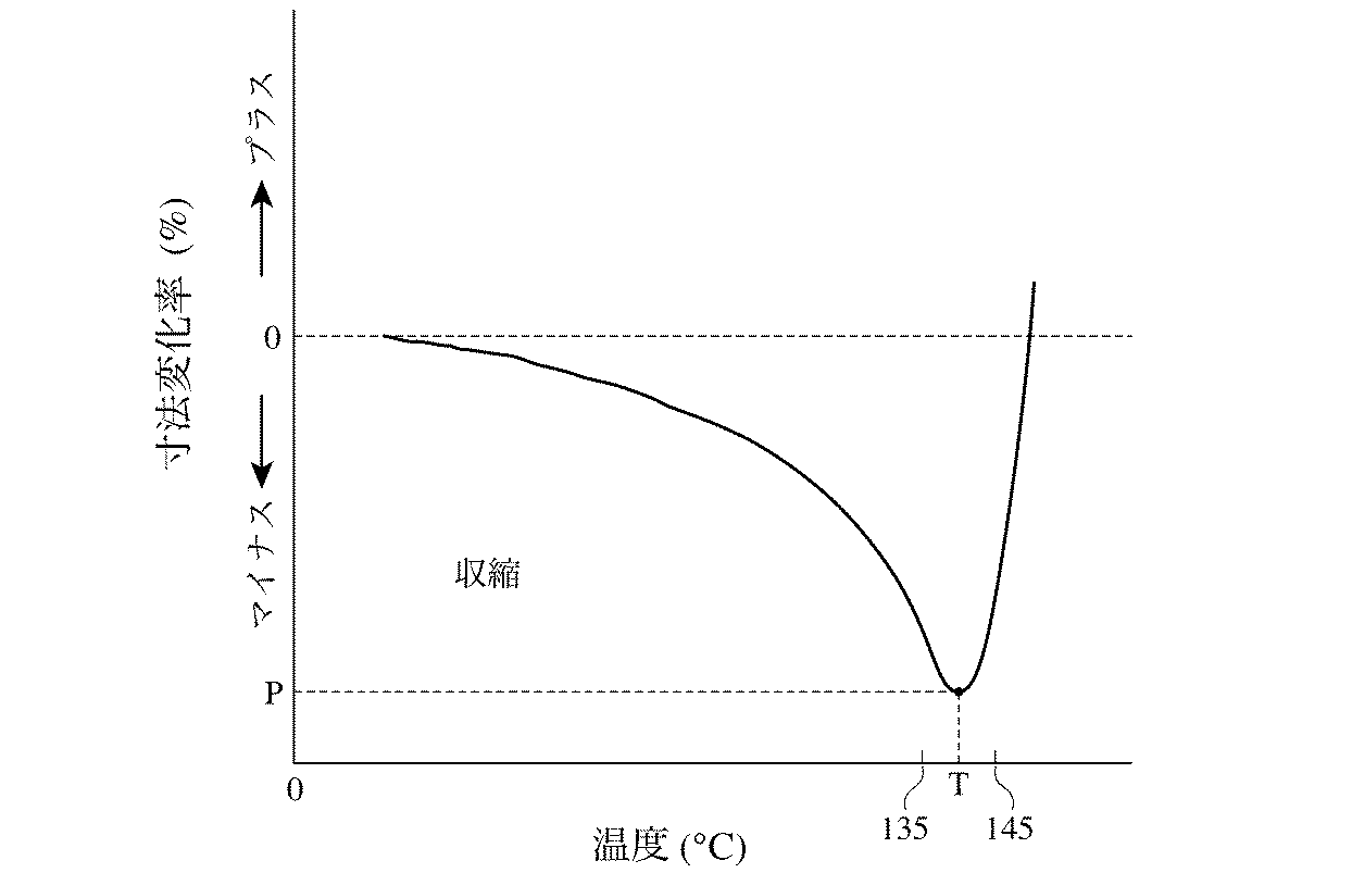
表1(続き)
表1(続き)
注:(1) Mwは重量平均分子量を表す。
(2) 溶融粘弾性測定により得られた貯蔵弾性率(G')及び損失弾性率(G'')が一致した角周波数。測定温度:180℃。
(3) MDは長手方向を表す。
(4) TDは横手方向を表す。
(5) L 3 は微多孔膜の熱緩和処理後の再延伸方向の長さを表す。
(6) L1は微多孔膜の再延伸前の再延伸方向の長さを表す。
Note: (1) Mw represents the weight average molecular weight.
(2) Angular frequency at which the storage elastic modulus (G ') and loss elastic modulus (G'') obtained by melt viscoelasticity measurement match. Measurement temperature: 180 ° C.
(3) MD represents the longitudinal direction.
(4) TD represents the lateral direction.
(5) L 3 represents the length in the re- stretching direction after the thermal relaxation treatment of the microporous membrane.
(6) L 1 represents the length of the microporous membrane in the re - stretching direction before re- stretching.
表1から明らかなように、実施例1〜5の微多孔膜は、ω0が0.01 rad/sec以上のPE組成物を用いて、118℃以上で延伸し、(a) 1.3〜1.5倍の範囲内で127℃以下で再延伸した後127℃以下で熱固定処理するか、(b) 式(1):1.3L1≦L 3 ≦1.5L1(ただしL1は微多孔膜の再延伸前の再延伸方向の長さであり、L 3 は微多孔膜の熱緩和処理後の再延伸方向の長さである)を満たすように、127℃以下で再延伸した後127℃以下で熱緩和処理することにより得た。これらの条件を満たしているので、これらの膜は、平均膜厚が23μm以上でありながら、20〜100 sec/100 cm3の範囲内の透気度、2,450 mN以上の突刺強度、及び12%以下の熱収縮率(105℃)を有すると考えられる。
As is clear from Table 1, the microporous membranes of Examples 1 to 5 were stretched at 118 ° C. or higher using a PE composition having an ω 0 of 0.01 rad / sec or higher, and (a) 1.3 to 1.5 times higher. Within the range, re-stretch at 127 ° C or lower and then heat-set at 127 ° C or lower, or (b) Formula (1): 1.3L 1 ≤ L 3 ≤ 1.5L 1 (where L 1 is the re-stretch of the microporous membrane) L 3 is the length in the previous re- stretching direction, and L 3 is the length in the re- stretching direction after the thermal relaxation treatment of the microporous membrane). Obtained by relaxation treatment. Since these conditions are met, these films have an average film thickness of 23 μm or more, air permeability in the range of 20-100 sec / 100 cm 3 , puncture strength of 2,450 mN or more, and 12% It is considered to have the following heat shrinkage (105 ° C.).
これに対して、比較例1及び2の微多孔膜は、ω0が0.01 rad/sec未満のPE組成物を用いたので、実施例1〜5の微多孔膜より突刺強度が劣っていた。比較例3の微多孔膜は、再延伸及び熱固定処理の温度が127℃超であるので、実施例1〜5の微多孔膜より透過性が劣っていた。比較例4の微多孔膜は、延伸温度が118℃未満で、再延伸及び熱固定処理の温度が127℃超であるので、実施例1〜5の微多孔膜より空孔率が低く、透過性及び耐溶融収縮性が劣っていた。比較例5の微多孔膜は、再延伸及び熱固定処理の温度が127℃超であるので、実施例1〜5の微多孔膜より透過性が劣り、空孔率も低かった。比較例6の微多孔膜は、延伸温度が118℃未満であるので、実施例1〜5の微多孔膜より耐熱収縮性が劣っていた。比較例7の微多孔膜は、再延伸の倍率が1.3倍未満であるので、実施例1〜5の微多孔膜より透過性が劣っていた。比較例8の微多孔膜は、再延伸の倍率が1.5倍超であるにもかかわらず、実施例1〜5の微多孔膜より耐熱収縮性が劣っていた。これは上記式(1)を満たす熱緩和処理を行っていないためと考えられる。 On the other hand, the microporous membranes of Comparative Examples 1 and 2 were inferior in puncture strength to the microporous membranes of Examples 1 to 5 because the PE composition having an ω 0 of less than 0.01 rad / sec was used. The microporous membrane of Comparative Example 3 was inferior in permeability to the microporous membranes of Examples 1 to 5 because the temperature of re-stretching and heat setting treatment was higher than 127 ° C. The microporous membrane of Comparative Example 4 has a lower stretching rate than the microporous membranes of Examples 1 to 5 because the stretching temperature is less than 118 ° C., and the temperature of the re-stretching and heat setting treatment exceeds 127 ° C. And melt shrinkage resistance were inferior. The microporous membrane of Comparative Example 5 had a lower retentivity and lower porosity than the microporous membranes of Examples 1 to 5 because the temperature of re-stretching and heat setting treatment exceeded 127 ° C. Since the stretching temperature of the microporous membrane of Comparative Example 6 was less than 118 ° C., the heat shrinkage resistance was inferior to that of the microporous membranes of Examples 1 to 5. The microporous membrane of Comparative Example 7 was inferior in permeability to the microporous membranes of Examples 1 to 5 because the redraw ratio was less than 1.3 times. The microporous membrane of Comparative Example 8 was inferior in heat shrinkage to the microporous membranes of Examples 1 to 5, despite the redrawing ratio exceeding 1.5 times. This is presumably because the thermal relaxation treatment satisfying the above formula (1) was not performed.
最後に、本発明の実施態様について以下の通り記載する。
[1] (1) 成膜用溶剤、及び0.01 rad/sec以上の粘弾性角周波数ω0(溶融粘弾性測定により得られる貯蔵弾性率G'及び損失弾性率G''が一致する角周波数)を有するポリエチレン系樹脂を混合してポリオレフィン溶液を調製し、
(2) 前記ポリオレフィン溶液を押し出して押出し成形体を形成し、前記押出し成形体を前記押出し成形体のゲル化温度以下まで冷却して冷却押出し成形体を形成し、
(3) 前記冷却押出し成形体を、約118℃以上の温度で延伸して延伸シートを形成し、
(4) 前記延伸シートから少なくとも一部の前記成膜用溶剤を除去して溶剤除去シートを形成し、
(5) (a) 再延伸前の再延伸方向の長さL1から、再延伸方向における最終的な長さL2まで、1.3L1≦L2≦1.5L1を満たすように、約127℃以下の膜温度でシートの少なくとも一側方にさらに前記溶剤除去シートを延伸し、再延伸シートを127℃以下で熱固定処理するか、
(b) 再延伸前の再延伸方向の長さL1から、再延伸方向における第二の長さL2まで、1.31L1≦L2≦2L1を満たすように、約127℃以下の膜温度でシートの少なくとも一側方にさらに前記溶剤除去シートを延伸し、1.3L1≦L3≦1.5L1(L3は熱緩和処理後の再延伸シートの再延伸方向における長さを表す)を満たす条件で熱緩和処理するポリオレフィン微多孔膜の製造方法。
[2] [1]に記載の方法において、さらに工程(4)と(5)の間に、前記溶剤除去シート中の少なくとも一部の揮発性の種を除去する工程を有する方法。
[3] [1]又は[2]に記載の方法において、さらに以下の工程:(6) 前記ポリオレフィン膜を熱緩和処理する工程、(7) 前記ポリオレフィン膜を架橋する工程、(8) 前記ポリオレフィン膜を親水化処理する工程、及び(9) 前記ポリオレフィン膜を多孔性物質でコーティングする工程のうちの少なくとも一つを任意の順で行う方法。
[4] [1]〜[3]のいずれかに記載の方法において、前記成膜用溶剤が、脂肪族、環式脂肪族又は芳香族の炭化水素、鉱油留分及びフタル酸エステルのうちの一種以上である方法。
[5] [1]〜[4]のいずれかに記載の方法において、前記第一の溶剤が、25℃の温度で約30〜約500 cStの粘度を有する流動パラフィンである方法。
[6] [1]〜[5]のいずれかに記載の方法において、(a) 前記ポリエチレン系樹脂と前記成膜用溶剤の混合を、ほぼ前記ポリエチレン系樹脂の融点から、前記ポリエチレン系樹脂の融点より約80℃高い温度の範囲で、二軸押出機中で溶融混練することにより行い、
(b) 前記ポリオレフィン溶液中の前記ポリオレフィンの量を、前記ポリオレフィン溶液の質量基準で、約1〜約75質量%の範囲とし、
(c) 長方形の口金を有し、約0.1〜約5mmの範囲のギャップを有する少なくとも一つのシート用ダイに、前記ポリオレフィン溶液を導き、押出しの間前記ポリオレフィン溶液を約140℃〜約250℃の温度に保持し、前記ポリオレフィン溶液の押出し速度を約0.2 m/分〜約15 m/分の範囲とし、
(d) 前記冷却工程(2)を50℃/分以上の冷却速度で行い、
(e) 前記延伸工程(3)を、前記冷却押出し成形体の第一及び第二の側方の少なくとも一方において約9〜約400倍の範囲の延伸倍率で行い、
(f) 塩素化炭化水素、エーテル、ケトン、鎖状フルオロカーボン、環状ハイドロフルオロカーボン、パーフルオロエーテル及びこれらの混合物である揮発性溶媒のうちの一種以上を含む洗浄溶媒により、前記延伸シートから前記成膜用溶剤を除去する方法。
[7] [1]〜[6]のいずれかに記載の方法において、前記ポリエチレン系樹脂が、(i) 約1×10⁶以上のMwを有するポリエチレン、(ii) 1×10⁶未満のMwを有するポリエチレン、又は(i)及び(ii)の両方を含む方法。
[8] [1]〜[7]のいずれかに記載の方法において、前記ポリオレフィン溶液が、ポリプロピレン、ポリブテン-1、ポリペンテン-1、ポリ-4-メチルペンテン-1、ポリヘキセン-1、ポリオクテン-1、ポリ酢酸ビニル、ポリメタクリル酸メチル、ポリスチレン及びエチレン・α-オレフィン共重合体からなる群から選ばれた少なくとも一種のポリエチレン系樹脂以外のポリオレフィンをさらに含む方法。
[9] [1]〜[8]のいずれかに記載の方法において、前記ポリエチレン系樹脂が、超高分子量ポリエチレン及び高密度ポリエチレンを含み、前記ポリオレフィン溶液が、さらに約1×10⁴〜約4×10⁶の範囲のMwを有するポリプロピレンを含む方法。
[10] [1]〜[9]のいずれかに記載の方法により製造されたポリオレフィン微多孔膜。
[11] (a) 透気度が20〜100 sec/100 cm3の範囲であり、(b) 突刺強度が2,450 mN以上であり、(c) 105℃での熱収縮率が12%以下であるポリオレフィン微多孔膜。
[12] [11]に記載の膜において、膜厚が約23μm以上である膜。
[13] [12]に記載の膜において、0.01 rad/sec以上の粘弾性角周波数ω0(溶融粘弾性測定により得られる貯蔵弾性率G'及び損失弾性率G''が一致する角周波数)を有するポリエチレンを含む膜。
[14] [11]〜[13]のいずれかに記載の膜において、前記ポリエチレンが、(i) 約1×10⁶以上のMwを有するポリエチレン、(ii) 1×10⁶未満のMwを有するポリエチレン、又は(i)及び(ii)の両方を含む膜。
[15] [14]に記載の膜において、前記約1×10⁶以上のMwを有するポリエチレンがエチレンホモポリマーである膜。
[16] [14]に記載の膜において、前記1×10⁶未満のMwを有するポリエチレンが、高密度ポリエチレン、中密度ポリエチレン、分岐状低密度ポリエチレン及び鎖状低密度ポリエチレンのうちの少なくとも一種である膜。
[17] [16]に記載の膜において、前記1×10⁶未満のMwを有するポリエチレンが、約1×10⁵〜約5×10⁵の範囲のMwを有する高密度ポリエチレンである膜。
[18] [14]に記載の膜において、ポリプロピレン、ポリブテン-1、ポリペンテン-1、ポリ-4-メチルペンテン-1、ポリヘキセン-1、ポリオクテン-1、ポリ酢酸ビニル、ポリメタクリル酸メチル、ポリスチレン及びエチレン・α-オレフィン共重合体からなる群から選ばれた少なくとも一種の第二のポリオレフィンをさらに含む膜。
[19] [18]に記載の膜において、前記ポリエチレンが超高分子量ポリエチレン及び高密度ポリエチレンであり、前記第二のポリオレフィンがポリプロピレンである膜。
[20] [10]〜[19]のいずれかに記載の膜からなる電池用セパレータ。
[21] 電解液、負極、正極並びに前記負極及び前記正極の間に配置されたセパレータを有し、前記セパレータが、0.01 rad/sec以上の粘弾性角周波数ω0(溶融粘弾性測定により得られる貯蔵弾性率G'及び損失弾性率G''が一致する角周波数)を有するポリエチレンを含み、(a) 12%以下の105℃での熱収縮率、(b) 約20〜100 sec/100 cm3の範囲の透気度(前記セパレータを電池に入れる前に測定)、(c) 2,450 mN以上の突刺強度、及び(d) 約23μm以上の膜厚を有する電池。
[22] [21]に記載の電池において、前記電池が、リチウムイオン二次電池、リチウムポリマー二次電池、ニッケル−水素二次電池、ニッケル−カドミウム二次電池、ニッケル−亜鉛二次電池、又は銀−亜鉛二次電池である電池。
[23] [21]又は[22]に記載の電池において、前記正極が、集電体と、その上に設けられたリチウムイオンを吸蔵放出可能な正極活物質層とを有する電池。
[24] [21]〜[23]のいずれかに記載の電池において、前記電解液が、有機溶媒に溶解したリチウム塩を含む電池。
[25] (1) 成膜用溶剤、及び0.01 rad/sec以上の粘弾性角周波数ω0(溶融粘弾性測定により得られる貯蔵弾性率G'及び損失弾性率G''が一致する角周波数)を有するポリエチレン系樹脂を混合してポリオレフィン溶液を調製し、
(2) 前記ポリオレフィン溶液を押し出して押出し成形体を形成し、前記押出し成形体を前記押出し成形体のゲル化温度以下まで冷却して冷却押出し成形体を形成し、
(3) 前記冷却押出し成形体を、約118℃以上の温度で延伸して延伸シートを形成し、
(4) 前記延伸シートから少なくとも一部の前記成膜用溶剤を除去して溶剤除去シートを形成し、
(5) (a) 再延伸前の再延伸方向の長さL1から、再延伸方向における最終的な長さL2まで、1.3L1≦L2≦1.5L1を満たすように、約127℃以下の膜温度でシートの少なくとも一側方にさらに前記溶剤除去シートを延伸し、再延伸シートを127℃以下で熱固定処理するか、
(b) 再延伸前の再延伸方向の長さL1から、再延伸方向における第二の長さL2まで、1.31L1≦L2≦2L1を満たすように、約127℃以下の膜温度でシートの少なくとも一側方にさらに前記溶剤除去シートを延伸し、1.3L1≦L3≦1.5L1(L3は熱緩和処理後の再延伸シートの再延伸方向における長さを表す)を満たす条件で熱緩和処理し、
(6) 前記セパレータの第一の表面の近傍に負極を配置し、前記セパレータの第二の表面の近傍に正極を配置し、リチウムイオンを含む電解液を前記セパレータに含浸させる電池の製造方法。
[26] [25]に記載の方法において、前記電池が二次電池である方法。
[27] [25]又は[26]に記載の方法において、前記セパレータが、(a) 12%以下の105℃での熱収縮率、(b) 約20〜100 sec/100 cm3の範囲の透気度(工程(6)の前に測定)、(c) 2,450 mN以上の突刺強度、及び(d) 約23μm以上の膜厚を有する方法。
[28] [25]〜[27]のいずれかに記載の方法において、さらに前記電池を、充電用のソース又はシンクとして用いる方法。
Finally, embodiments of the present invention are described as follows.
[1] (1) Film-forming solvent and viscoelastic angular frequency ω 0 of 0.01 rad / sec or more (the angular frequency at which the storage elastic modulus G ′ and loss elastic modulus G ″ obtained by melt viscoelasticity measurement coincide) A polyolefin solution is prepared by mixing a polyethylene resin having
(2) Extruding the polyolefin solution to form an extruded molded body, cooling the extruded molded body to a temperature below the gelation temperature of the extruded molded body to form a cooled extruded molded body,
(3) The cooled extruded body is stretched at a temperature of about 118 ° C. or higher to form a stretched sheet,
(4) removing at least a portion of the film-forming solvent from the stretched sheet to form a solvent removal sheet,
(5) (a) From the length L 1 in the re-stretching direction before re-stretching to the final length L 2 in the re- stretching direction, about 127 so as to satisfy 1.3L 1 ≦ L 2 ≦ 1.5L 1 The solvent removal sheet is further stretched on at least one side of the sheet at a film temperature of ℃ or less, or the re-stretched sheet is heat-set at 127 ℃ or less,
(b) A film of about 127 ° C. or less so as to satisfy 1.31L 1 ≦ L 2 ≦ 2L 1 from the length L 1 in the re-stretch direction before re-stretching to the second length L 2 in the re- stretch direction The solvent-removed sheet is further stretched on at least one side of the sheet at a temperature, and 1.3 L 1 ≦ L 3 ≦ 1.5 L 1 (L 3 represents the length in the re- stretching direction of the re -stretched sheet after the thermal relaxation treatment) The manufacturing method of the polyolefin microporous film which heat-treats on the conditions which satisfy | fill.
[2] The method according to [1], further comprising a step of removing at least a part of volatile species in the solvent removal sheet between the steps (4) and (5).
[3] In the method according to [1] or [2], the following steps are further performed: (6) a step of thermally relaxing the polyolefin film, (7) a step of crosslinking the polyolefin film, (8) the polyolefin A method of performing at least one of a step of hydrophilizing the membrane and (9) a step of coating the polyolefin membrane with a porous material in an arbitrary order.
[4] In the method according to any one of [1] to [3], the film-forming solvent is selected from the group consisting of aliphatic, cycloaliphatic or aromatic hydrocarbons, mineral oil fractions, and phthalates. A method that is more than one kind.
[5] The method according to any one of [1] to [4], wherein the first solvent is liquid paraffin having a viscosity of about 30 to about 500 cSt at a temperature of 25 ° C.
[6] In the method according to any one of [1] to [5], (a) the mixing of the polyethylene resin and the film-forming solvent is performed from the melting point of the polyethylene resin approximately from the melting point of the polyethylene resin. Performed by melting and kneading in a twin screw extruder at a temperature range about 80 ° C higher than the melting point,
(b) the amount of the polyolefin in the polyolefin solution is in the range of about 1 to about 75 mass% based on the mass of the polyolefin solution;
(c) directing the polyolefin solution to at least one sheet die having a rectangular base and having a gap in the range of about 0.1 to about 5 mm; and during extrusion, the polyolefin solution is about 140 ° C to about 250 ° C. Holding the temperature, the extrusion rate of the polyolefin solution is in the range of about 0.2 m / min to about 15 m / min,
(d) performing the cooling step (2) at a cooling rate of 50 ° C./min or more,
(e) The stretching step (3) is performed at a stretching ratio in the range of about 9 to about 400 times on at least one of the first and second sides of the cooled extrudate.
(f) Forming the film from the stretched sheet with a cleaning solvent containing one or more of volatile solvents which are chlorinated hydrocarbons, ethers, ketones, chain fluorocarbons, cyclic hydrofluorocarbons, perfluoroethers and mixtures thereof. To remove the solvent.
[7] The method according to any one of [1] to [6], wherein the polyethylene-based resin is (i) polyethylene having Mw of about 1 × 10 6 or more, (ii) Mw of less than 1 × 10 6 Or a process comprising both (i) and (ii).
[8] In the method according to any one of [1] to [7], the polyolefin solution is polypropylene, polybutene-1, polypentene-1, poly-4-methylpentene-1, polyhexene-1, polyoctene-1 And a method further comprising at least one polyolefin other than polyethylene resin selected from the group consisting of polyvinyl acetate, polymethyl methacrylate, polystyrene, and ethylene / α-olefin copolymers.
[9] In the method according to any one of [1] to [8], the polyethylene-based resin includes ultrahigh molecular weight polyethylene and high-density polyethylene, and the polyolefin solution is further about 1 × 10 4 to about 4 A process comprising polypropylene having a Mw in the range of 10 6 .
[10] A polyolefin microporous membrane produced by the method according to any one of [1] to [9].
[11] (a) an air permeability in the range of 20~100 sec / 100 cm 3, ( b) is a pin puncture strength of 2,450 mN or more, (c) a thermal shrinkage at 105 ° C. is 12% or less A polyolefin microporous membrane.
[12] The film according to [11], wherein the film thickness is about 23 μm or more.
[13] In the film according to [12], a viscoelastic angular frequency ω 0 of 0.01 rad / sec or more (an angular frequency at which a storage elastic modulus G ′ and a loss elastic modulus G ″ obtained by melt viscoelasticity measurement coincide) A membrane comprising polyethylene having
[14] In the membrane according to any one of [11] to [13], the polyethylene has (i) polyethylene having an Mw of about 1 × 10 6 or more, and (ii) an Mw of less than 1 × 10 6 A membrane comprising polyethylene or both (i) and (ii).
[15] The membrane according to [14], wherein the polyethylene having an Mw of about 1 × 10 6 or more is an ethylene homopolymer.
[16] In the film according to [14], the polyethylene having an Mw of less than 1 × 10 6 is at least one of high density polyethylene, medium density polyethylene, branched low density polyethylene, and chain low density polyethylene. A membrane.
[17] The membrane according to [16], wherein the polyethylene having an Mw of less than 1 × 10 6 is a high-density polyethylene having an Mw in the range of about 1 × 10 5 to about 5 × 10 5 .
[18] In the film according to [14], polypropylene, polybutene-1, polypentene-1, poly-4-methylpentene-1, polyhexene-1, polyoctene-1, polyvinyl acetate, polymethyl methacrylate, polystyrene, and A film further comprising at least one second polyolefin selected from the group consisting of ethylene / α-olefin copolymers.
[19] The membrane according to [18], wherein the polyethylene is ultrahigh molecular weight polyethylene and high-density polyethylene, and the second polyolefin is polypropylene.
[20] A battery separator comprising the film according to any one of [10] to [19].
[21] An electrolyte, a negative electrode, a positive electrode, and a separator disposed between the negative electrode and the positive electrode, the separator having a viscoelastic angular frequency ω 0 (obtained by melt viscoelasticity measurement of 0.01 rad / sec or more) (A) thermal shrinkage at 105 ° C. of 12% or less, (b) about 20-100 sec / 100 cm A battery having an air permeability in the range of 3 (measured before inserting the separator into the battery), (c) a puncture strength of 2,450 mN or more, and (d) a film thickness of about 23 μm or more.
[22] The battery according to [21], wherein the battery is a lithium ion secondary battery, a lithium polymer secondary battery, a nickel-hydrogen secondary battery, a nickel-cadmium secondary battery, a nickel-zinc secondary battery, or A battery which is a silver-zinc secondary battery.
[23] The battery according to [21] or [22], wherein the positive electrode includes a current collector and a positive electrode active material layer provided thereon that can occlude and release lithium ions.
[24] The battery according to any one of [21] to [23], wherein the electrolytic solution contains a lithium salt dissolved in an organic solvent.
[25] (1) Solvent for film formation and viscoelastic angular frequency ω 0 of 0.01 rad / sec or more (an angular frequency at which the storage elastic modulus G ′ and loss elastic modulus G ″ obtained by melt viscoelasticity measurement coincide) A polyolefin solution is prepared by mixing a polyethylene resin having
(2) Extruding the polyolefin solution to form an extruded molded body, cooling the extruded molded body to a temperature below the gelation temperature of the extruded molded body to form a cooled extruded molded body,
(3) The cooled extruded body is stretched at a temperature of about 118 ° C. or higher to form a stretched sheet,
(4) removing at least a portion of the film-forming solvent from the stretched sheet to form a solvent removal sheet,
(5) (a) From the length L 1 in the re-stretching direction before re-stretching to the final length L 2 in the re- stretching direction, about 127 so as to satisfy 1.3L 1 ≦ L 2 ≦ 1.5L 1 The solvent removal sheet is further stretched on at least one side of the sheet at a film temperature of ℃ or less, or the re-stretched sheet is heat-set at 127 ℃ or less,
(b) A film of about 127 ° C. or less so as to satisfy 1.31L 1 ≦ L 2 ≦ 2L 1 from the length L 1 in the re-stretch direction before re-stretching to the second length L 2 in the re- stretch direction The solvent-removed sheet is further stretched on at least one side of the sheet at a temperature, and 1.3 L 1 ≦ L 3 ≦ 1.5 L 1 (L 3 represents the length in the re- stretching direction of the re -stretched sheet after the thermal relaxation treatment) Heat relaxation treatment under conditions that satisfy
(6) A battery manufacturing method in which a negative electrode is disposed in the vicinity of the first surface of the separator, a positive electrode is disposed in the vicinity of the second surface of the separator, and the separator is impregnated with an electrolytic solution.
[26] The method according to [25], wherein the battery is a secondary battery.
[27] In the method according to [25] or [26], the separator is (a) a thermal shrinkage rate at 105 ° C. of 12% or less, and (b) in the range of about 20 to 100 sec / 100 cm 3 . A method having air permeability (measured before step (6)), (c) a puncture strength of 2,450 mN or more, and (d) a film thickness of about 23 μm or more.
[28] The method according to any one of [25] to [27], wherein the battery is further used as a charging source or sink.
Claims (6)
(1) 成膜用溶剤、及び0.01 rad/sec以上の粘弾性角周波数ω0を有するポリエチレン系樹脂を混合してポリオレフィン溶液を調製し、
(2) 前記ポリオレフィン溶液を押し出して押出し成形体を形成し、前記押出し成形体を前記押出し成形体のゲル化温度以下まで冷却して冷却押出し成形体を形成し、
(3) 前記冷却押出し成形体を、118℃以上の温度で延伸して延伸シートを形成し、
(4) 前記延伸シートから少なくとも一部の前記成膜用溶剤を除去して溶剤除去シートを形成し、
(5) (a)再延伸前の再延伸方向の長さL1から、再延伸方向における最終的な長さL2まで、1.3L1≦L2≦1.5L1を満たすように、127℃以下の膜温度でシートの少なくとも一側方にさらに前記溶剤除去シートを延伸し、再延伸シートを127℃以下で熱固定処理するか、
(b)再延伸前の再延伸方向の長さL1から、再延伸方向における第二の長さL2まで、1.31L1≦L2≦2L1を満たすように、127℃以下の膜温度でシートの少なくとも一側方にさらに前記溶剤除去シートを延伸し、1.3L1≦L3≦1.5L1(L3は熱緩和処理後の再延伸シートの再延伸方向における長さを表す)を満たす条件で熱緩和処理する
ことを特徴とするポリオレフィン微多孔膜の製造方法。 A method for producing the polyolefin microporous membrane according to claim 1 or 2,
(1) A polyolefin solution is prepared by mixing a film-forming solvent and a polyethylene resin having a viscoelastic angular frequency ω 0 of 0.01 rad / sec or more,
(2) Extruding the polyolefin solution to form an extruded molded body, cooling the extruded molded body to a temperature below the gelation temperature of the extruded molded body to form a cooled extruded molded body,
(3) The cooled extruded product is stretched at a temperature of 118 ° C. or higher to form a stretched sheet,
(4) removing at least a portion of the film-forming solvent from the stretched sheet to form a solvent removal sheet,
(5) (a) From the length L 1 in the re-stretching direction before re-stretching to the final length L 2 in the re- stretching direction, 127 ° C. so as to satisfy 1.3L 1 ≦ L 2 ≦ 1.5L 1 The solvent removal sheet is further stretched on at least one side of the sheet at the following film temperature, and the restretched sheet is heat-set at 127 ° C. or lower,
(b) From the length L 1 in the re-stretching direction before re-stretching to the second length L 2 in the re- stretching direction, a film temperature of 127 ° C. or less so as to satisfy 1.31L 1 ≦ L 2 ≦ 2L 1 Then, the solvent-removed sheet is further stretched on at least one side of the sheet, and 1.3L 1 ≦ L 3 ≦ 1.5L 1 (L 3 represents the length in the re- stretching direction of the re -stretched sheet after the thermal relaxation treatment) A method for producing a polyolefin microporous membrane, wherein a thermal relaxation treatment is performed under a satisfying condition.
6. The battery according to claim 5, wherein the battery is a lithium ion secondary battery, a lithium polymer secondary battery, a nickel-hydrogen secondary battery, a nickel-cadmium secondary battery, a nickel-zinc secondary battery, or a silver-zinc. A battery characterized by being a secondary battery.
Priority Applications (1)
| Application Number | Priority Date | Filing Date | Title |
|---|---|---|---|
| JP2010508640A JP5497635B2 (en) | 2007-08-31 | 2008-08-29 | Polyolefin microporous membrane, method for producing the same, battery separator and battery |
Applications Claiming Priority (4)
| Application Number | Priority Date | Filing Date | Title |
|---|---|---|---|
| JP2007226898 | 2007-08-31 | ||
| JP2007226898 | 2007-08-31 | ||
| PCT/JP2008/066030 WO2009028737A1 (en) | 2007-08-31 | 2008-08-29 | Microporous polyolefin membrane, its production method, battery separator and battery |
| JP2010508640A JP5497635B2 (en) | 2007-08-31 | 2008-08-29 | Polyolefin microporous membrane, method for producing the same, battery separator and battery |
Publications (3)
| Publication Number | Publication Date |
|---|---|
| JP2010538097A JP2010538097A (en) | 2010-12-09 |
| JP2010538097A5 JP2010538097A5 (en) | 2011-09-29 |
| JP5497635B2 true JP5497635B2 (en) | 2014-05-21 |
Family
ID=40387432
Family Applications (1)
| Application Number | Title | Priority Date | Filing Date |
|---|---|---|---|
| JP2010508640A Active JP5497635B2 (en) | 2007-08-31 | 2008-08-29 | Polyolefin microporous membrane, method for producing the same, battery separator and battery |
Country Status (5)
| Country | Link |
|---|---|
| US (1) | US8414663B2 (en) |
| JP (1) | JP5497635B2 (en) |
| KR (1) | KR101477176B1 (en) |
| CN (1) | CN101796108B (en) |
| WO (1) | WO2009028737A1 (en) |
Families Citing this family (39)
| Publication number | Priority date | Publication date | Assignee | Title |
|---|---|---|---|---|
| JP5614746B2 (en) | 2009-03-06 | 2014-10-29 | 国立大学法人群馬大学 | Method for producing ultra high molecular weight polyethylene film |
| JP2013166804A (en) * | 2010-06-04 | 2013-08-29 | Toray Battery Separator Film Co Ltd | Polyolefin microporous membrane, separator for battery and battery |
| WO2012090632A1 (en) * | 2010-12-28 | 2012-07-05 | 旭化成イーマテリアルズ株式会社 | Polyolefin porous membrane and method of producing the same |
| CN102751459B (en) | 2011-04-22 | 2016-03-23 | 天津东皋膜技术有限公司 | Rear cross-linked rubber, the micro-porous septum of composite polyolefine material nanometer and manufacture method thereof |
| KR20140048147A (en) * | 2011-06-08 | 2014-04-23 | 도레이 카부시키가이샤 | Porous polypropylene film and process for manufacturing same |
| WO2013031795A1 (en) * | 2011-08-31 | 2013-03-07 | 三井化学株式会社 | Polyolefin resin composition and applications thereof |
| WO2013099539A1 (en) * | 2011-12-26 | 2013-07-04 | 東レバッテリーセパレータフィルム株式会社 | Polyolefin microporous film, polyolefin microporous film roll, method for producing polyolefin microporous film or polyolefin microporous film roll, and separator for batteries using polyolefin microporous film or polyolefin microporous film roll |
| CN102627796B (en) * | 2012-04-11 | 2015-06-03 | 中国科学院化学研究所 | Polyethylene composition for manufacturing lithium battery diaphragm |
| TWI453114B (en) * | 2012-05-11 | 2014-09-21 | Entire Technology Co Ltd | Manufacturing method for porous composite film |
| KR101611229B1 (en) * | 2013-01-31 | 2016-04-11 | 제일모직 주식회사 | Method for manufacturing separator, the separator, and battery using the separator |
| KR101350602B1 (en) * | 2013-02-12 | 2014-01-13 | 삼성토탈 주식회사 | The production methods of polyolefin separators including far-infrared and/or tenter annealing devices |
| JP5857151B2 (en) * | 2013-02-27 | 2016-02-10 | 東レバッテリーセパレータフィルム株式会社 | Polyolefin porous membrane, battery separator using the same, and production method thereof |
| CN103342849B (en) * | 2013-07-24 | 2015-06-03 | 黑龙江省化工研究院 | Modified polyethylene material for preventing and curing soil loss |
| KR101523433B1 (en) * | 2013-10-11 | 2015-05-27 | 주식회사 효성 | Multilayered microporous film with excellent heat-resistance and preparation method thereof |
| CN103951881B (en) * | 2014-04-12 | 2016-06-08 | 安徽江威精密制造有限公司 | A kind of resistance to high pressure is resisted and is worn electrical condenser metallized film and its preparation method |
| KR20160002447A (en) * | 2014-06-30 | 2016-01-08 | 제일모직주식회사 | Porous polyolefin separator and a method for preparing the same |
| JP6202062B2 (en) * | 2014-09-30 | 2017-09-27 | 住友化学株式会社 | Method for measuring strength of polarizing film and polarizing plate |
| JP7156942B2 (en) * | 2015-09-18 | 2022-10-19 | セルガード エルエルシー | Improved membranes, calendered microporous membranes, battery separators, and related methods |
| US10153474B1 (en) * | 2015-09-30 | 2018-12-11 | Apple Inc. | Separators having improved temperature ranges for battery shutdown |
| JP5969683B1 (en) * | 2015-11-30 | 2016-08-17 | 住友化学株式会社 | Nonaqueous electrolyte secondary battery separator, nonaqueous electrolyte secondary battery laminate separator, nonaqueous electrolyte secondary battery member, and nonaqueous electrolyte secondary battery |
| JP6822070B2 (en) * | 2016-02-17 | 2021-01-27 | 東ソー株式会社 | Ultra-high molecular weight polyethylene composition and stretched microporous membrane made of it |
| JP6878841B2 (en) * | 2016-03-11 | 2021-06-02 | 東ソー株式会社 | Separator made of ultra high molecular weight polyethylene composition |
| US9966591B1 (en) | 2016-12-19 | 2018-05-08 | StoreDot Ltd. | Electrode stack production methods |
| WO2018116295A1 (en) * | 2016-12-19 | 2018-06-28 | StoreDot Ltd. | Layer preparation, treatment, transfer and lamination in cell stack assembly processes for lithium ion batteries |
| US10033023B2 (en) | 2016-12-19 | 2018-07-24 | StoreDot Ltd. | Surface activation in electrode stack production and electrode-preparation systems and methods |
| JP6986873B2 (en) * | 2017-06-27 | 2021-12-22 | 住友化学株式会社 | Synthetic resin microporous film, separator for power storage device and power storage device |
| EP3677625B1 (en) | 2017-08-31 | 2021-12-08 | Asahi Kasei Kabushiki Kaisha | Polyolefin microporous membrane |
| WO2019073595A1 (en) * | 2017-10-13 | 2019-04-18 | Necエナジーデバイス株式会社 | Lithium-ion secondary battery |
| CN113226525A (en) * | 2018-12-27 | 2021-08-06 | 3M创新有限公司 | Asymmetric hollow fiber membranes and methods of making and using the same |
| CN113226526B (en) * | 2018-12-27 | 2024-05-14 | 舒万诺知识产权公司 | Hollow fiber membranes with nucleating agents and methods of making and using the same |
| KR102642401B1 (en) * | 2019-03-13 | 2024-02-28 | 주식회사 엘지화학 | Manufacturing method of crosslinked polyolefin separator |
| US20220389203A1 (en) * | 2019-10-08 | 2022-12-08 | Asahi Kasei Kabushiki Kaisha | Polyolefin Microporous Membrane |
| WO2022006217A1 (en) * | 2020-07-01 | 2022-01-06 | Celanese International Corporation | Polymer composition and membranes made therefrom with improved mechanical strength |
| US20240006624A1 (en) * | 2020-12-14 | 2024-01-04 | Amtek Research International Llc | Free-standing, ion-selective composite membranes |
| JP7609507B2 (en) * | 2020-12-25 | 2025-01-07 | 旭化成バッテリーセパレータ株式会社 | Molding resin raw material composition, microporous membrane resin raw material composition, and manufacturing method thereof |
| KR102592442B1 (en) * | 2021-11-26 | 2023-10-25 | 더블유스코프코리아 주식회사 | A separator and a method for manufacturing the same |
| CN114883742B (en) * | 2022-05-17 | 2023-02-28 | 东华大学 | A kind of preparation method of porous low-shrinkage polypropylene diaphragm for lithium ion battery |
| JP7750917B2 (en) * | 2023-02-17 | 2025-10-07 | 旭化成株式会社 | Polyethylene composition and molded article |
| JP7661441B2 (en) * | 2023-02-17 | 2025-04-14 | 旭化成株式会社 | Polyethylene composition and molded article |
Family Cites Families (12)
| Publication number | Priority date | Publication date | Assignee | Title |
|---|---|---|---|---|
| JP2657430B2 (en) | 1991-01-30 | 1997-09-24 | 東燃株式会社 | Polyolefin microporous membrane and method for producing the same |
| JPH1121361A (en) | 1997-07-07 | 1999-01-26 | Mitsubishi Chem Corp | Polyethylene resin porous film |
| JPH1121362A (en) | 1997-07-07 | 1999-01-26 | Mitsubishi Chem Corp | Polyethylene resin porous film |
| CA2275891C (en) * | 1997-10-23 | 2008-12-23 | Tonen Chemical Corporation | Method of producing highly permeable microporous polyolefin membrane |
| DE19983047B4 (en) * | 1998-03-24 | 2005-12-15 | Asahi Kasei Chemicals Corporation | Microporous polyolefin membrane |
| WO2000020493A1 (en) * | 1998-10-01 | 2000-04-13 | Tonen Chemical Corporation | Microporous polyolefin film and process for producing the same |
| WO2000049074A1 (en) * | 1999-02-19 | 2000-08-24 | Tonen Chemical Corporation | Polyolefin microporous film and method for preparing the same |
| JP4794098B2 (en) * | 2001-09-28 | 2011-10-12 | 東レ東燃機能膜合同会社 | Method for producing polyolefin microporous membrane |
| JP4195810B2 (en) * | 2002-12-16 | 2008-12-17 | 東燃化学株式会社 | Polyolefin microporous membrane and production method and use thereof |
| US20070012617A1 (en) * | 2003-09-05 | 2007-01-18 | Sadakatsu Suzuki | Method for producing micro-porous film of thermoplastic resin |
| RU2418821C2 (en) * | 2005-03-31 | 2011-05-20 | Тонен Кемикал Корпорейшн | Method of producing microporous polyolefin membranes and microporous membranes |
| KR101340393B1 (en) * | 2005-11-24 | 2013-12-11 | 도레이 배터리 세퍼레이터 필름 주식회사 | Microporous polyolefin membrane, process for producing the same, separator for cell, and cell |
-
2008
- 2008-08-29 JP JP2010508640A patent/JP5497635B2/en active Active
- 2008-08-29 KR KR1020107007054A patent/KR101477176B1/en active Active
- 2008-08-29 CN CN2008801051183A patent/CN101796108B/en active Active
- 2008-08-29 US US12/675,737 patent/US8414663B2/en active Active
- 2008-08-29 WO PCT/JP2008/066030 patent/WO2009028737A1/en not_active Ceased
Also Published As
| Publication number | Publication date |
|---|---|
| JP2010538097A (en) | 2010-12-09 |
| CN101796108B (en) | 2012-08-22 |
| WO2009028737A1 (en) | 2009-03-05 |
| US8414663B2 (en) | 2013-04-09 |
| CN101796108A (en) | 2010-08-04 |
| KR20100082830A (en) | 2010-07-20 |
| KR101477176B1 (en) | 2014-12-29 |
| US20100209745A1 (en) | 2010-08-19 |
Similar Documents
| Publication | Publication Date | Title |
|---|---|---|
| JP5497635B2 (en) | Polyolefin microporous membrane, method for producing the same, battery separator and battery | |
| JP5312450B2 (en) | Polyolefin multilayer microporous membrane, method for producing the same, battery separator and battery | |
| JP5202826B2 (en) | Polyethylene microporous membrane, method for producing the same, and battery separator | |
| TWI402172B (en) | Microporous polyolefin membrane, its production method, battery separator, and battery | |
| JP5250261B2 (en) | Polyolefin microporous membrane and battery separator and battery using the same | |
| JP5596768B2 (en) | Polyethylene microporous membrane and battery separator | |
| KR101372983B1 (en) | Microporous polyolefin membrane, its production method, battery separator, and battery | |
| JP5422562B2 (en) | Polymer microporous membrane | |
| JP4902455B2 (en) | Polyolefin multilayer microporous membrane, method for producing the same, battery separator and battery | |
| KR101389781B1 (en) | Microporous polyolefin membrane, its production method, battery separator, and battery | |
| CN101855751B (en) | Microporous membranes and methods for making and using such membranes | |
| JP5450929B2 (en) | Polyolefin multilayer microporous membrane, method for producing the same, battery separator and battery | |
| JP5250262B2 (en) | Polyolefin microporous membrane and method for producing the same, battery separator and battery | |
| JP5450944B2 (en) | Polyolefin microporous membrane, battery separator and battery | |
| US20090042008A1 (en) | Microporous polyolefin membrane, its production method, battery separator and battery | |
| KR20220069831A (en) | Polyolefin microporous membrane, battery separator and secondary battery |
Legal Events
| Date | Code | Title | Description |
|---|---|---|---|
| A711 | Notification of change in applicant |
Free format text: JAPANESE INTERMEDIATE CODE: A711 Effective date: 20110331 |
|
| A521 | Request for written amendment filed |
Free format text: JAPANESE INTERMEDIATE CODE: A523 Effective date: 20110810 |
|
| A621 | Written request for application examination |
Free format text: JAPANESE INTERMEDIATE CODE: A621 Effective date: 20110810 |
|
| A131 | Notification of reasons for refusal |
Free format text: JAPANESE INTERMEDIATE CODE: A131 Effective date: 20130827 |
|
| A521 | Request for written amendment filed |
Free format text: JAPANESE INTERMEDIATE CODE: A523 Effective date: 20131007 |
|
| TRDD | Decision of grant or rejection written | ||
| A01 | Written decision to grant a patent or to grant a registration (utility model) |
Free format text: JAPANESE INTERMEDIATE CODE: A01 Effective date: 20140225 |
|
| A61 | First payment of annual fees (during grant procedure) |
Free format text: JAPANESE INTERMEDIATE CODE: A61 Effective date: 20140306 |
|
| R150 | Certificate of patent or registration of utility model |
Ref document number: 5497635 Country of ref document: JP Free format text: JAPANESE INTERMEDIATE CODE: R150 |
|
| R250 | Receipt of annual fees |
Free format text: JAPANESE INTERMEDIATE CODE: R250 |
|
| S111 | Request for change of ownership or part of ownership |
Free format text: JAPANESE INTERMEDIATE CODE: R313111 |
|
| R350 | Written notification of registration of transfer |
Free format text: JAPANESE INTERMEDIATE CODE: R350 |