JP5496891B2 - Conveyor and transmission belt - Google Patents
Conveyor and transmission belt Download PDFInfo
- Publication number
- JP5496891B2 JP5496891B2 JP2010523584A JP2010523584A JP5496891B2 JP 5496891 B2 JP5496891 B2 JP 5496891B2 JP 2010523584 A JP2010523584 A JP 2010523584A JP 2010523584 A JP2010523584 A JP 2010523584A JP 5496891 B2 JP5496891 B2 JP 5496891B2
- Authority
- JP
- Japan
- Prior art keywords
- belt
- conveyor
- trunnion
- strip
- scraper
- Prior art date
- Legal status (The legal status is an assumption and is not a legal conclusion. Google has not performed a legal analysis and makes no representation as to the accuracy of the status listed.)
- Expired - Fee Related
Links
Images


Classifications
-
- B—PERFORMING OPERATIONS; TRANSPORTING
- B65—CONVEYING; PACKING; STORING; HANDLING THIN OR FILAMENTARY MATERIAL
- B65G—TRANSPORT OR STORAGE DEVICES, e.g. CONVEYORS FOR LOADING OR TIPPING, SHOP CONVEYOR SYSTEMS OR PNEUMATIC TUBE CONVEYORS
- B65G17/00—Conveyors having an endless traction element, e.g. a chain, transmitting movement to a continuous or substantially-continuous load-carrying surface or to a series of individual load-carriers; Endless-chain conveyors in which the chains form the load-carrying surface
- B65G17/30—Details; Auxiliary devices
- B65G17/38—Chains or like traction elements; Connections between traction elements and load-carriers
-
- B—PERFORMING OPERATIONS; TRANSPORTING
- B65—CONVEYING; PACKING; STORING; HANDLING THIN OR FILAMENTARY MATERIAL
- B65G—TRANSPORT OR STORAGE DEVICES, e.g. CONVEYORS FOR LOADING OR TIPPING, SHOP CONVEYOR SYSTEMS OR PNEUMATIC TUBE CONVEYORS
- B65G15/00—Conveyors having endless load-conveying surfaces, i.e. belts and like continuous members, to which tractive effort is transmitted by means other than endless driving elements of similar configuration
- B65G15/30—Belts or like endless load-carriers
- B65G15/48—Belts or like endless load-carriers metallic
-
- B—PERFORMING OPERATIONS; TRANSPORTING
- B65—CONVEYING; PACKING; STORING; HANDLING THIN OR FILAMENTARY MATERIAL
- B65G—TRANSPORT OR STORAGE DEVICES, e.g. CONVEYORS FOR LOADING OR TIPPING, SHOP CONVEYOR SYSTEMS OR PNEUMATIC TUBE CONVEYORS
- B65G19/00—Conveyors comprising an impeller or a series of impellers carried by an endless traction element and arranged to move articles or materials over a supporting surface or underlying material, e.g. endless scraper conveyors
- B65G19/18—Details
- B65G19/20—Traction chains, ropes, or cables
Landscapes
- Engineering & Computer Science (AREA)
- Mechanical Engineering (AREA)
- Structure Of Belt Conveyors (AREA)
- Belt Conveyors (AREA)
- Rollers For Roller Conveyors For Transfer (AREA)
Description
本発明は、ある場所から別の場所へ物品を移送するのに使用することができ、すなわち伝動ベルトとして使用することができるコンベヤのような、ベルトおよびコンベヤに関するが、必ずしもそれだけに限定されない。 The present invention relates to, but is not necessarily limited to, belts and conveyors, such as conveyors that can be used to transfer articles from one location to another, i.e. used as a transmission belt.
従来技術では、エンドレス・ベルトまたはチェーンの形態のコンベヤが周知である。チェーンまたはロープを備え、ベルトに沿ったある点で駆動されるエンドレス・ベルトは、その表面に直接載せるか、またはベルトに連結されたバケットなどから懸吊して品物を運ぶことができる。そのようなシステムが、欧州特許出願公開第0352047号に記載されている。
In the prior art, conveyors in the form of endless belts or chains are well known. An endless belt comprising a chain or rope and driven at some point along the belt can carry items directly on its surface or suspended from a bucket or the like connected to the belt. Such a system is described in
互いに接合されたリンクを備えるチェーンおよび他のベルトは、それらが固着しないように頻繁に潤滑する必要があることは周知である。そのような潤滑は不都合である。 It is well known that chains and other belts with links joined together need to be frequently lubricated to prevent them from sticking. Such lubrication is inconvenient.
別の知られているシステムは、いわゆるフローティング・フライト・スクレーパ・コンベヤである。このコンベヤは、通常、進行方向に沿って移動する2つのエンドレス・チェーンと、進行方向に対して横切る方向で両チェーン間に取り付けられた複数のスクレーパ・バーとを備え、スクレーパ・バーはチェーンに対して枢動可能に取り付けられている。そのような場合には、通常は穀類などのばら材である移送物は、コンベヤがその中に取り付けられている外筐に沿ってスクレーパ・バーによって掻引される。 Another known system is the so-called floating flight scraper conveyor. This conveyor usually comprises two endless chains that move along the direction of travel, and a plurality of scraper bars mounted between the chains in a direction transverse to the direction of travel, with the scraper bars attached to the chain. It is pivotally attached to it. In such cases, the transport, usually a bulk material such as cereal, is scraped by a scraper bar along the outer casing in which the conveyor is mounted.
本発明の第1の態様によれば、コンベヤまたは伝動ベルトを形成するベルトであって、実質的に非伸張性であるが弾性的に可撓であり、互いに強固に固定されてエンドレス・ベルトを形成する少なくとも1つの、しかし好ましくは複数の平らな細片を備えるベルトが提供される。 According to a first aspect of the present invention, a belt forming a conveyor or transmission belt, which is substantially non-stretchable but elastically flexible and is firmly fixed to each other to form an endless belt. A belt is provided comprising at least one but preferably a plurality of flat strips to form.
全ての細片が互いに強固に固定されているので、潤滑などの必要が無い。細片の可撓の性質は、それら細片が、コンベヤを案内する任意の案内ホイールなどの周りに曲げることができ、したがって継ぎ手の必要がないことを意味する。ベルトが曲がることによって、互いに擦れ合う部品の必要性をなくすことができるので、典型的にはチェーンに基づくシステムなどの従来技術に比較して、この種のコンベヤによって発せられる騒音もまた低減することができる。そのコンベヤは、伝動ベルトとしても利用することができる。そのような場合、物品を運ぶために使用する代わりに、ベルトは、ある要素から別の要素へ運動を伝達するために使用することができる。 Since all the strips are firmly fixed to each other, there is no need for lubrication or the like. The flexible nature of the strips means that they can be bent around any guide wheel or the like that guides the conveyor, thus eliminating the need for a joint. As the belt bends, the need for parts to rub against each other can be eliminated, so that the noise emitted by this type of conveyor can also be reduced as compared to conventional techniques such as chain-based systems. it can. The conveyor can also be used as a transmission belt. In such a case, instead of being used to carry the article, the belt can be used to transfer motion from one element to another.
以後、複数の細片に言及する場合、別段文脈で必要とされない限り、単数も含めることに留意されたい。 Note that hereinafter, when referring to a plurality of strips, the singular is also included unless otherwise required by the context.
好ましくは、互いに細片は一定の間隔で締結され、細片は、これを達成するために、一定の間隔をおいて鍵形にされ得る。細片は一定の長さとすることができる。 Preferably, the strips are fastened together at regular intervals, and the strips can be keyed at regular intervals to achieve this. The strip can be of a certain length.
好ましい実施形態では、細片はばね鋼などの金属または金属素材を含む。ばね鋼は、その弾性特性および引張強度が本発明によって必要とされる通りのものであるので、細片を製作するのに特に好都合な材料であることが分かっている。ばね鋼はまた、現行の最新の製造技術を用いて、製造するのがより経済的であり、加工するのに好都合である。 In a preferred embodiment, the strip comprises a metal such as spring steel or a metal material. Spring steel has been found to be a particularly convenient material for making strips because its elastic properties and tensile strength are as required by the present invention. Spring steel is also more economical to manufacture and convenient to process using current state-of-the-art manufacturing techniques.
好ましくは、細片は細長く、また長さ方向でその面外へ曲げる際に弾性的に可撓である。好ましくは、細片は、幅方向でその面外へ曲げるのが、長さ方向でその面外へ曲げるよりも難しい。細片同士は、通常、引張強度が低下することのない連継する細片の短い両端部を接合するようにして、長さ方向に接合することができる。 Preferably, the strip is elongated and elastically flexible when bent out of plane in the longitudinal direction. Preferably, the strip is more difficult to bend out of the plane in the width direction than it is out of the plane in the length direction. The strips can usually be joined in the length direction by joining the short ends of the continuous strips without decreasing the tensile strength.
コンベヤは、エンドレス・ベルト沿いに間隔をおいてエンドレス・ベルトに固定された複数のトラニオンを備えることができる。トラニオンの使用は、ベルトがコンベヤの他の部品とより容易に相互作用することができるので、有用である。トラニオンは、ベルトに固定されたほぼ円筒形の本体を備えることができ、円筒形本体の軸は、ベルトの長さに直角をなすが、細片の面内にある。したがって、そのような位置に固定されたトラニオンは、エンドレス・ベルトに力を加えるのに使用することができる。 The conveyor may comprise a plurality of trunnions secured to the endless belt at intervals along the endless belt. The use of trunnions is useful because the belt can more easily interact with other parts of the conveyor. The trunnion can comprise a generally cylindrical body secured to the belt, the axis of the cylindrical body being perpendicular to the length of the belt but in the plane of the strip. Thus, a trunnion fixed in such a position can be used to apply force to the endless belt.
トラニオンそれぞれが、円筒形本体上に嵌められたローラを備えることができ、ローラは本体に対して自由に回転することができる。これによって、ベルトが、そうでなければその上を摺動するであろう物体上を転がり走行することができ、それによって、摩擦が減少する。しかし、トラニオンがローラを備えるとは限らず、そのような場合、トラニオン、またはトラニオンがその上を摺動する物体のいずれかを、低摩擦プラスチック材などの低摩擦材料から製作してもよい。 Each trunnion can include a roller fitted on the cylindrical body, the roller being free to rotate relative to the body. This allows the belt to roll over an object that would otherwise slide on it, thereby reducing friction. However, the trunnion does not necessarily comprise a roller, and in such a case either the trunnion or the object on which the trunnion slides may be made from a low friction material such as a low friction plastic material.
トラニオンは、エンドレス・ベルトに沿って、一定の間隔で、好ましくは正確な間隔で設けることができる。このために、細片は、トラニオンおよび/またはローラを配置するべく鍵形にされ得る。細片は、一定の長さのものとすることができ、それぞれ一定の位置に鍵形が形成され得る。これは、トラニオンを一定間隔で確実に配置するのに好都合な態様である。一定間隔で配置することは、それによって、エンドレス・ベルトを駆動するのにトラニオンを使用することができるので、有利である。 Trunnions can be provided along the endless belt at regular intervals, preferably precisely. For this purpose, the strips can be keyed to place trunnions and / or rollers. The strips can be of a certain length and each can be keyed at a certain position. This is an advantageous way to ensure that the trunnions are placed at regular intervals. Arranging at regular intervals is advantageous because it allows the trunnion to be used to drive the endless belt.
コンベヤは、細片の面内で互いに同一平面内にある2つの前述のエンドレス・ベルトを備えることができる。2つのベルトは、通常一定の間隔で互いに接合され得る。ベルトはまた、各トラニオンが両方のベルトに固定されることにより、トラニオンによって接合され得る。トラニオンとは別々に2つのベルトを接合すると、ベルトへのトラニオンの組付けが大いに容易になる。 The conveyor can comprise two aforementioned endless belts that are coplanar with each other in the plane of the strip. The two belts can usually be joined together at regular intervals. The belts can also be joined by trunnions, with each trunnion being secured to both belts. Joining the two belts separately from the trunnion greatly facilitates the assembly of the trunnion to the belt.
好ましくは、各トラニオンの円筒形本体は2つの端部を有する。すなわち、一方のベルトに好ましくは鍵形部分で係合する第1の端部と、他方のベルトに好ましくは鍵形部分で係合する第2の端部である。これにより、ベルトが駆動されるときトラニオンに掛かる捩じり力が減少する。ローラが、通常、トラニオンがほぼ対称になるように、第1の端部と第2の端部との間の本体に配置され得る。 Preferably, the cylindrical body of each trunnion has two ends. That is, a first end engaged with one belt, preferably with a key-shaped portion, and a second end engaged with the other belt, preferably with a key-shaped portion. This reduces the torsional force applied to the trunnion when the belt is driven. A roller can typically be placed in the body between the first and second ends so that the trunnion is substantially symmetrical.
コンベヤは、エンドレス・ベルトに係合する少なくとも1つの駆動または案内ホイールを備えることができ、それらホイールは、ベルトに沿うトラニオンと同じ間隔でその外周周りに配置された窪みを有する少なくとも1つのほぼ円形のスプロケットを備える。窪みは、ローラまたはトラニオンの本体を受け入れるような寸法および形状とすることができる。ホイールはまた、前記ベルトまたは各ベルトがホイールの周りを通るときのそれらの支持部を備えることができ、その支持部は円筒形円盤を備えることができ、使用中、ベルトはその円盤の外周縁部上に支持される。そのような円盤は2枚あってもよく、それら円盤は、スプロケットと同軸にその両側に取り付けられ得る。 The conveyor can include at least one drive or guide wheel that engages an endless belt, the wheel having at least one generally circular shape with indentations disposed about its outer periphery at the same spacing as the trunnions along the belt. Equipped with a sprocket. The recess may be sized and shaped to receive a roller or trunnion body. The wheel can also comprise a support for said belt or each belt as it passes around the wheel, the support can comprise a cylindrical disk, and in use, the belt is the outer periphery of the disk. Supported on the part. There may be two such disks, which can be mounted on both sides coaxially with the sprocket.
トラニオンの代わりに、またはそれに追加して、エンドレス・ベルトが、一定間隔で配置された駆動スロットを備えることができ、コンベヤが、突出した歯を通常用いてスロットに係合するような形状の駆動ホイールを備えることができる。これは、コンベヤが伝動ベルトとして使用される場合に特に適用され、それは、他の物品をベルト自体に装着することを必要とする可能性が殆どないからである。 Instead of or in addition to the trunnion, the endless belt can be provided with regularly spaced drive slots, and the conveyor is configured to engage the slots normally using protruding teeth A wheel can be provided. This is particularly true when the conveyor is used as a transmission belt, as it is unlikely that other articles will need to be attached to the belt itself.
各トラニオンは、駆動スロット内に設けることができる。駆動スロットは、トラニオンがベルトの長さに沿う方向に付勢されたとき、トラニオンがベルトに段差を介して付勢力を伝達するように配置された段差をその外周に有することができる。したがって、外周に、トラニオンの両側に離間配置された2つの段差があり得る。 Each trunnion can be provided in a drive slot. The drive slot may have a step on its outer periphery arranged such that when the trunnion is urged in a direction along the length of the belt, the trunnion transmits a urging force to the belt through the step. Therefore, there can be two steps on the outer periphery that are spaced apart on both sides of the trunnion.
駆動ホイールがトラニオン用の窪みを備えている場合に、駆動ホイールはまた、ベルトの駆動スロットに係合するように配置された複数の案内ピンを備えることができる。この案内ピンは、トラニオンを駆動ホイールに確実に正確に係合させる。案内ピンは、硬化鋼から形成することができる。 Where the drive wheel includes trunnion depressions, the drive wheel may also include a plurality of guide pins arranged to engage the drive slots of the belt. This guide pin ensures that the trunnion engages the drive wheel accurately. The guide pin can be formed from hardened steel.
駆動ホイールを形成するために、コンベヤは、駆動ホイールを回転的に駆動することができるように配置された電気または油圧モータなどの駆動手段を備えることができ、それにより、好ましくはトラニオンを駆動ホイールに係合させることによってエンドレス・ベルトを駆動する。あるいは、案内ホイールを形成するには、ホイールは動力なしでよい。 In order to form the drive wheel, the conveyor can be equipped with drive means such as an electric or hydraulic motor arranged so that the drive wheel can be driven in rotation, thereby preferably driving the trunnion to the drive wheel. To drive the endless belt. Alternatively, the wheel may be unpowered to form a guide wheel.
通常、案内ホイールを設ける場合には、ホイールはまた、張力装置も備えることができ、それによってエンドレス・ベルトのテンションを制御することができる。通常、前記エンドレス・ベルトまたは各エンドレス・ベルトはホイールを廻って通り、張力装置は、ホイールの軸に、その軸に垂直な力を加えるように配置される。これにより、前記ベルトまたは各ベルトのテンションを制御することができる。 Typically, if a guide wheel is provided, the wheel can also be equipped with a tensioning device, whereby the tension of the endless belt can be controlled. Typically, the endless belt or each endless belt passes around the wheel, and the tensioning device is arranged to apply a force perpendicular to the axis of the wheel. Thereby, the tension of the belt or each belt can be controlled.
ベルトは、バケットやスクレーパなどの搬送器用の支持部を備えることができる。前記支持部または各支持部はトラニオンに備えることができる。支持部は、前記エンドレス・ベルトまたは各エンドレス・ベルトから離れて延出するアームを備えることができる。アームから懸吊されるバケットを設けることができる。 The belt can include a support for a transporter such as a bucket or a scraper. The said support part or each support part can be provided in a trunnion. The support portion may include the endless belt or an arm extending away from each endless belt. A bucket suspended from the arm can be provided.
代替形態では、搬送器用の支持部が、細片の面外へ弾性的に曲げることができる、細片の屈曲可能部分を備えることができる。したがって、これにより、支持部に関して「ばね復帰」を形成することができ、その結果、支持部が、屈曲可能部分によって中立位置に付勢される。屈曲可能部分は、溝によって画成されるベルトのタングの形態であり得る。溝は、タングをベルト本体の内側に設ける場合にはU字形であってもよく、一方、タングをベルトの長手方向縁部に設けるために溝をベルトの縁部に設ける場合にはL字形であってもよい。 In an alternative, the support for the transporter can comprise a bendable portion of the strip that can be elastically bent out of the plane of the strip. Thus, this can form a “spring return” with respect to the support, with the result that the support is biased to the neutral position by the bendable part. The bendable portion may be in the form of a belt tongue defined by a groove. The groove may be U-shaped when the tongue is provided inside the belt body, while the groove is L-shaped when the groove is provided at the belt edge to provide the tongue at the longitudinal edge of the belt. There may be.
ベルトは、搬送器用の支持部、または搬送器自体によって互いに接合され得る。この場合、支持部はさらに、屈曲可能部分に取り付けられたバーを備えることができ、バケットまたは他の搬送器が任意選択的にバーに取り付けられる。搬送器はカムを備えることができ、そのとき、コンベヤは、コンベヤが動くとカムが追従するカム面をさらに備えることができ、それによって前記ベルトまたは各ベルトに対する搬送器の向きが制御される。 The belts can be joined together by a support for the transporter or by the transporter itself. In this case, the support may further comprise a bar attached to the bendable portion, and a bucket or other transporter is optionally attached to the bar. The transporter can comprise a cam, at which time the conveyor can further comprise a cam surface that the cam follows as the conveyor moves, thereby controlling the orientation of the transporter relative to the belt or each belt.
搬送器がスクレーパを備える場合、スクレーパの中立位置はベルトの面内にあり得る。スクレーパは、適切な面と協働してコンベヤの適切な位置でスクレーパを中立位置から押し出すカム部分を備えることができる。コンベヤが駆動または案内ホイールをも備える場合には、ホイールもまた適切な面として作用し得る。したがって、スクレーパは、所望されないときは行路外へ畳まれているが、必要なときには有効な位置に付勢させることができる。 If the transporter comprises a scraper, the neutral position of the scraper may be in the plane of the belt. The scraper can include a cam portion that cooperates with an appropriate surface to push the scraper out of the neutral position at an appropriate position on the conveyor. If the conveyor is also equipped with a drive or guide wheel, the wheel can also act as a suitable surface. Thus, the scraper is folded out of the way when not desired, but can be biased to an effective position when necessary.
エンドレス・ベルト上の、細片が互いに接合される点では、2つの細片間に重ね合わせ部分が形成され得る。すなわち、結合箇所では、細片同士の面が平行に重ね合わさるように、平らな細片の一方が他方の細片に重なり得る。細片は、重複領域で連結され得る。トラニオンは、重ね合わせ部分で複数の細片を共に保持することができ、少なくとも1つ、好ましくは少なくとも2つのトラニオンが、各重ね合わせ部分に設けられ得る。 At the point on the endless belt where the strips are joined together, an overlap can be formed between the two strips. That is, at the joining location, one of the flat strips can overlap the other strip so that the surfaces of the strips overlap in parallel. The strips can be joined at overlapping regions. The trunnion can hold a plurality of strips together in the overlapping portion, and at least one, and preferably at least two trunnions can be provided in each overlapping portion.
次いで、単なる例示として、添付図面を参照して記載される本発明の実施形態が以下に続く。 Then, by way of example only, embodiments of the invention described below with reference to the accompanying drawings follow.
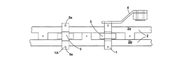
本発明の第1の実施形態によるコンベヤ・システムが、図1〜5、および7に示され、2つのエンドレス・ベルト2a、2bを備える。これらのベルトのそれぞれは、複数の細長く平らなばね鋼製の細片を備える。それら細片は、長さ方向に強固に接合されて、エンドレス・ベルト2a、2bを形成する。2つのベルトは、各細片対を連結するタブ1aによって接合される。細片を長さ方向でその面外へ曲げることに関する細片の弾性特性によって、細片によって形成されたベルトをそれ自体の上に(矢印20の方向に)曲げ戻すことが可能になり、それによってエンドレス・ベルトが形成される。
A conveyor system according to a first embodiment of the invention is shown in FIGS. 1-5 and 7 and comprises two
ベルトに沿って一定間隔で、トラニオン1が設けられる。これらトラニオンが、2つのベルトを一定の正確な間隔で連結する。トラニオンは、一方のベルトから他方のベルトに延在し両ベルトに強固に取り付けられた円筒形本体1bと、両ベルト2間で本体に回転可能に取り付けられたローラ3とを備える。2つのベルトはタブによって互いに接合されているので、トラニオンを正確な位置に組み付けることは比較的容易である。
トラニオン1には、また、バケットなどの搬送器用の取付け点を設けることもでき、図1にはバケットを取り付けることができるバケット・アーム4が示されている。
The
図2および3は、どのようにトラニオン1をエンドレス・ベルトに固定するかを示す。各細片は、その長さに沿って一定間隔で規則的に配置された鍵形部分5を有する。これら鍵形部分は、トラニオン1の本体1aにあるスロット7に係合する。各鍵形部分は、また、孔5aを有する。対応する孔6が、トラニオン1の実施形態に見られ、図3a〜3cのA位置に示されている。このトラニオン1が鍵形部分5にわたって正確に取り付けられると、孔5aおよび孔6が整合し、孔5a、6を貫通させてピン(図示せず)を通して、トラニオンをエンドレス・ベルトに沿って正確な間隔で確実に配置することができる。ピンは、実質的に引張りまたは長手方向荷重を受けない。これは、引張りまたは長手方向荷重は、トラニオンを鍵形部分5に配置することによって取り除かれるからである。
2 and 3 show how the
代替のトラニオン1が、図3aおよび3bにBで示されている。それは、射出成形プラスチックで形成され、ピン16を用いて鋼細片を貫通してピン留めされている。同じピン16が、バケット・アーム4をトラニオン本体の端部に連結するために使用されているが、アーム4およびトラニオンを一体部品として射出成形することもできる。
An
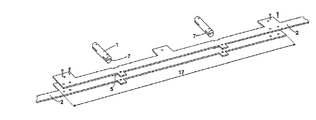
エンドレス・ベルトを製作するために連継する2つの細片を連結するところが、添付図面の図4a〜4cに示されている。両細片2が、その長さに沿って重複領域17の端から端へ重なり合う。この重複領域は、2つのトラニオン1取付け点および連結タブ1aを包含する。トラニオン1は、鍵形部分5を跨いで取り付けられ、2つの細片2により増加した厚さを受け入れるために特別な厚さのスロット7を有する。連継する細片を互いに位置決めする、トラニオンのピン18が図4bに示されている。それに加えて、あるいはその代わりに、細片は19に示すように固定することができる。
The connection of two strips that are joined to produce an endless belt is shown in FIGS. 4a-4c of the accompanying drawings. Both strips 2 overlap along the length of the
エンドレス・ベルト2を案内し、駆動するのに使用される駆動ホイール10aおよび案内ホイール10bが、添付図面の図5および7に示されている。ホイール10a、10bは、ローラ3の寸法および形状に対合する窪み12を有するスプロケット・ホイールの形態のホイールである。スプロケット・ホイールの外周周りの窪みの正確な間隔はエンドレス・ベルトに沿ったトラニオンの間隔にマッチする。使用中、ローラは窪み12に係合し、そのときエンドレス・ベルトは、スプロケット・ホイール10a、10bの両側に同軸に取り付けられ、直径がそれらにマッチする2つの支持ホイール20上に支持される。
A
駆動ホイール10aの場合は、モータ9が、ベルト駆動部8を用いてスプロケット・ホイール10aを駆動する。モータ9が駆動ホイール10aを回転させると、窪み12が、ローラ3に係合し、それらローラ3、そしてトラニオン1、したがってエンドレス・ベルト2をホイール周りに動かす。これによって、エンドレス・ベルト2を全長に亘って移動させる。
In the case of the
図5bに示される案内ホイール10bは、無動力であり、したがって、たとえば駆動ホイール10aによって駆動されるなど、エンドレス・ベルトのいかなる移動によっても回転する。しかし、エンドレス・ベルト2のテンションを制御するために、テンション装置13が設けられている。この装置が、案内ホイール10b用に移動可能な車軸を形成し、それによって、案内ホイールがエンドレス・ベルトに対して移動して、ベルトのテンションを制御することができる。
The
代替のベルトが、添付図面の図3dに示される。そのベルトは、正確な間隔で切り取られた切抜き部30を有するスロット付き単一細片から形成される。そのベルトは、切抜き部30に係合することができる突出歯34を有する、図8に示される駆動ホイールと共に使用される。
An alternative belt is shown in Figure 3d of the accompanying drawings. The belt is formed from a single slotted strip with
細片は、バケット・アーム4などを装着するためのクリアランスを可能にする長手方向窪みを備える。さらに、細片は、ベルトを形成する複数の細片が正確に互いに接合され得るようにする鍵形部分31を有する。
The strip is provided with a longitudinal recess that allows clearance for mounting a bucket arm 4 or the like. In addition, the strip has a key-shaped
図6a〜6dは、その他の図のコンベヤ・システムに可能な使用法を示す。2つの上記のコンベヤ・システム14が設けられており、トラニオン1はそれぞれバケット・アーム4を備える。コンベヤ・システム14は互いに同一平面にあるが、互いに離隔している。各システム14のトラニオン1は整合している。両コンベヤ・システム14間で、バケット18が、対応するバケット・アーム4の各対の間に取り付けられている。
6a-6d show possible uses for the conveyor system of the other figures. Two of the
このバケット・コンベヤ・システムは、欧州特許出願公開第0352047号に記載のバケット・コンベヤ・システムとして十分に使用することができる。例示的システムが、添付図面の図6cおよび6dに概略的に示される。コンベヤは、14として示されている。図6cの視点では、細片の長い薄い側方が見え、図6dでは細片の面が見える。
This bucket conveyor system can be used satisfactorily as the bucket conveyor system described in
図6cおよび6dの配置では、バケット18は、その配置の最下部のロード点15で積載される。駆動ホイール10aが、エンドレス・ベルトにシステムを廻って移動させ、バケットをアンロード点16および17まで駆動する。複数の案内ホイール10bが、コンベヤ・システムの行路のあちこちに、コンベヤ・システムの行路を変更しようとする度毎に設けられ、実際には各端部および角部に設けられる。
In the arrangement of FIGS. 6c and 6d, the
この実施形態、実際には、本発明のコンベヤ・システムは全体として、従来技術のコンベアに比較して可動部分の数が削減され、潤滑の必要性が低減され、引張強度が改善されているので、有利である。そのコンベヤ・システムは、バケット・コンベヤ、スラット・タイプ、プラットホーム・タイプ、またはトレイ・タイプ・コンベヤ、垂直トレイまたは折畳式プラットホーム・コンベヤ、ドラッグ・リンク・コンベヤ、管状フライト・タイプ・コンベヤなど、様々なコンベヤ・システムに関して使用することができる。 In this embodiment, in fact, the conveyor system of the present invention as a whole has a reduced number of moving parts, reduced need for lubrication and improved tensile strength compared to prior art conveyors. Is advantageous. Its conveyor systems include bucket conveyor, slat type, platform type, or tray type conveyor, vertical tray or foldable platform conveyor, drag link conveyor, tubular flight type conveyor, etc. Can be used with any conveyor system.
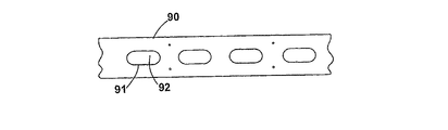
本発明の第2の実施形態では、本発明によるコンベヤは、伝動ベルトとして使用することもできる。これが、添付図面の図9a〜9cに示されている。図9a〜9cに示されるベルトは、様々な状況にいかにベルトを適合させることができるかを示すために、ベルトの幅だけを変化させている。図9aは幅25mmのバー、図9bは幅20mmのバー、図9cは幅15mmのバーを示す。 In a second embodiment of the invention, the conveyor according to the invention can also be used as a transmission belt. This is illustrated in Figures 9a-9c of the accompanying drawings. The belt shown in FIGS. 9a-9c only changes the width of the belt to show how it can be adapted to various situations. 9a shows a 25 mm wide bar, FIG. 9b shows a 20 mm wide bar, and FIG. 9c shows a 15 mm wide bar.
各ベルト90は、前と同様、複数のばね鋼または弾性的に変形可能なプラスチックの細片を備える。伝動ベルト90は、ベルトの中心線92に沿って一定間隔で配置された一連の孔91を備える。細片のそれぞれは、たとえば3つまたは5つの複数の孔91を有することができ、少なくとも1つの孔で両細片が重なり合うように互いに接合され得る。
Each
したがって、これらのベルトは、添付図面の図8に示されるような駆動ホイールと共に使用することができる。そのベルトは、伝動部材に可動部品を必要としないという利点を有して、伝動チェーンまたはベルトを置き換えるのに好都合に使用することができる。さらに、ベルトの弾性特性は、ベルトを張る必要性を減少させ、または完全に無くすことができることを意味し、伝動システムの複雑さが取り除かれる。 Therefore, these belts can be used with a drive wheel as shown in FIG. 8 of the accompanying drawings. The belt can be advantageously used to replace a transmission chain or belt, with the advantage of not requiring moving parts in the transmission member. Furthermore, the elastic properties of the belt mean that the need to tension the belt can be reduced or eliminated completely, eliminating the complexity of the transmission system.
本発明の第3の実施形態を、添付図面の図10〜12に見ることができる。図面の図11から分かるように、この実施形態は2つのベルト100を備え、その1つがより詳細に添付図面の図10に示されている。各ベルト100は、以前に説明した通り、重ね合わせて締結された複数の細片を備える。細片は、ばね鋼から製作される。細片、したがって各ベルトは、添付図面の図8に示される形態の駆動ホイールに係合することができる、一定間隔で配置された駆動孔101を有する。
A third embodiment of the present invention can be seen in FIGS. As can be seen from FIG. 11 of the drawings, this embodiment comprises two
ベルト100は、また、細片を切り抜き、一定間隔で配置されたU字形溝102を備える。各溝は、ベルトにタング103を画成する。細片がばね鋼から製造されているので、タング103は、ベルトの面外へ弾性的に曲げることができるが、ばね鋼細片の弾性変形による本来のばね力によってベルトの面内の中立位置に付勢されて戻る。
The
これが、本実施形態のコンベヤ・システムで利用される。添付図面の図11に示すように、コンベヤ・システムは、2つのベルト100を連結する。支持バー104が、各ベルト100から1つずつのタング103の対を連結する。したがって、各支持バー104は、ベルトの面外へ動かすことができるが、ベルトとの接触位置へ付勢されて戻る。
This is used in the conveyor system of this embodiment. As shown in FIG. 11 of the accompanying drawings, the conveyor system connects two
各支持バー104は、その上にバケット105を担持する。添付図面の図11の支持バー104a上のバケットは明瞭化のために省かれている。したがって、バケットは、タング103の付勢作用に対抗する何らかの力がバケットに働かない限り、普通はベルト100の面内にあり、その開口面もベルトの面内位置にある。
Each
この実施形態のコンベヤ・システムの要素を添付図面の図12a〜12cに見ることができる。バケット105はそれぞれ、バケット105から突出するカム106を備える。カムがいかなる面とも係合していない場合は、カムは、ベルトに対するバケットの運動に主要な作用を及ぼさず、バケットは、その重量およびタングのばね力に応答する。しかし、カム106が面107a、107bに係合すると、カムは、バケットを通常の位置から押し出すことができる。
The elements of the conveyor system of this embodiment can be seen in Figures 12a-12c of the accompanying drawings. Each
したがって、これは、ベルト100に対するバケット105の向きを制御するために使用することができる。図12a〜12bでは、ベルトが、垂直に曲がりくねる行路を辿るとき、カムが、バケットを水平に保つために使用されている。面107a、107bを適切な角度で設けることによって、バケットを図のように水平にし、またはバケットの中味を空にするためにひっくり返すことでさえ、バケットをいかなる所望の角度にでも設定することができる。
This can therefore be used to control the orientation of the
図12cでは、カムは使用されていないが、バケット105自体が、それ自体を面107cに載せて配向している。
In FIG. 12c, no cams are used, but the
本発明によるコンベヤの第4の実施形態が、添付図面の図13〜16に示されている。前例同様、この実施形態は、長さ方向に接合された複数の平らな鋼細片から構成されたベルト200を備える。ベルト200は、外筐201の中を通る。この実施形態は、穀類などのばら材を外筐の内側に沿って掻引することによって移動させるためにスクレーパを使用する。ベルトは、規則的なタブ202a、202bを備え、それらタブは、ベルトを構成する細片の鋼材から切り出されているのでばね状である。駆動スプロケット214もまた設けられている。
A fourth embodiment of a conveyor according to the invention is shown in FIGS. 13-16 of the accompanying drawings. Like the previous example, this embodiment comprises a
2種類のタブ202aが設けられている。中央タブ202aは、ベルト200の中心部で、内部の切抜き部分203に設けられている。このタブは、添付図面の図15に示される(図13に輪郭が示される)中央スクレーパ205を備える。中央スクレーパ206は、タブ202aに強固に取り付けられた装着部分と、アーム208上で装着部分206から延出するスクレーパ部分207とを備える。
Two types of
他方の種類のタブは、側方タブ202bである。それは、インデント209によってベルト200の側部内側に取り付けられる。このタブ202bは、添付図面の図13に輪郭が、添付図面の図14にはより詳細に示される側方スクレーパ210を備える。やはり、その側方スクレーパは、装着部分211と、アーム213上で装着部分211から延出するスクレーパ部分212とを備える。
The other type of tab is a
側方スクレーパ205と中央スクレーパ210とは極めて類似しており、側方スクレーパ210の取付け手段211が、ベルトの両側のインデント209内に取り付けられるので、非対称である点と、アーム213が、スクレーパ部分212とその側面部で接合する点とが異なるだけであることがわかる。中央スクレーパの装着手段206は対称であり、アーム208は、スクレーパ部分207の側面中央部でスクレーパに接合する。
The
この配置の効果を、図13の平面図に対応する側面図を示す添付図面の図16に見ることができる。この図は、スクレーパの1つが、外筐201の壁の間で遊動することができることを示す。3つの異なる位置A、B、およびCに示されているスクレーパは、負荷および何らかの外力がそのスクレーパに掛けられているか否かに応じて、そのスクレーパのタブ202a/202bによるばね力に対抗して枢動することができる。
The effect of this arrangement can be seen in FIG. 16 of the accompanying drawings showing a side view corresponding to the plan view of FIG. This figure shows that one of the scrapers can move between the walls of the
両方のタイプのタブおよびスクレーパを共に使用することができるが、通常、いずれか一方のみが使用される。 Both types of tabs and scrapers can be used together, but usually only one is used.
そのようなコンベヤを使用したコンベヤ・システムが添付図面の図17に示される。ベルト200は、エンドレスであり、複数のプーリ250上を通過し、それらプーリのいくつかまたは全ては駆動することができ、それによって、駆動スプロケット214を用いてベルト200を駆動する。テンションプーリ250aが、ベルトのテンションを制御するために設けられている。
A conveyor system using such a conveyor is shown in FIG. 17 of the accompanying drawings. The
コンベヤ・システムは、ばら材が外筐201に投入される捕捉区域251で移送する材料を取り込む。ここでは中央スクレーパ205として示されるスクレーパが、矢印252の方向にベルトが駆動されるにつれて、材料を外筐201の側面に抗して掻引する。
The conveyor system takes in the material to be transferred in the
スクレーパは、ベルトがプーリ250からプーリ250へ最短ルートに沿って通るので、外筐の縁部に対するベルトの位置に基づいてその位置が定まり、これは、捕捉区域251上の垂直直線部252に見ることができ、そこでは、スクレーパ205が、移送する材料を担持しながら外筐の一方の側面から他方の側面へ遊動する。
As the belt passes along the shortest route from
選択的に開けることができる開口254が、移送する材料の排出区域を形成し、その材料は捕捉区域251から排出区域254まで移送されたことになる。
The
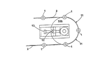
本実施形態によるコンベヤの第5の実施形態を、添付図面の図18および19に見ることができる。この実施形態は、エンドレス・ベルトを形成するために長さ方向に接合された複数の平らな鋼細片の形態の2つのベルト300を備える。ベルトは、その面内に延在するタブ301を備え、タブは、それらが製作された鋼の弾性特性によって、実効的にばね状である。一方のベルトのタブ301は、他方のベルトのタブと整合している。
A fifth embodiment of a conveyor according to this embodiment can be seen in FIGS. 18 and 19 of the accompanying drawings. This embodiment comprises two
整合するタブ301の各対は、それらの間に遊動スクレーパ302を取り付けるために使用される。遊動スクレーパは、各タブ301に装着されるアーム303を備える。アームは、ベルト300の面にほぼ垂直な面内にあるが、ベルト300の長さに平行なループの形態である。ループの端部は互いに平行でありタブに装着され、ループは、タブ301から延出して離れるにつれて幅広になる。ループの形状は対称である。
Each pair of matching
スクレーパ部分304が、2つのアーム303の間で、2つのループの内側に取り付けられている。スクレーパ部分304は、2つのアーム間のバーとして形成されている。スクレーパ部分304は、ループの、タブ303から最も遠い部分に取り付けられており、その結果、スクレーパ302は全体として対称面を有する。この対称面は、タブがその残りのベルトに整合したとき、ベルト300の面と同一平面になり、そのとき、タブ301によってスクレーパに加えられるばね力を考慮すると、スクレーパは中立位置にある。
A
そのようなコンベヤを使用したコンベヤ・システムを添付図面の図20および21に見ることができる。図20は装置の下側半分を示し、図21は上端を示す。 A conveyor system using such a conveyor can be seen in FIGS. 20 and 21 of the accompanying drawings. FIG. 20 shows the lower half of the device and FIG. 21 shows the upper end.
図17のコンベヤ・システムと同様に、ベルト300は、一連のプーリ350(以下に説明されるプーリ350a、350bを含めて)によって規定される行路上を走行し、それらの間で最短ルートを取る。ベルト300は外筐351内を走行する。
Similar to the conveyor system of FIG. 17,
コンベヤ・システムは、ばら材が外筐351に投入される捕捉区域352からばら材を移送する。コンベヤは、矢印353で示される方向に、プーリ350の駆動用のプーリによって駆動される。
The conveyor system transfers the bulk material from a
ベルト300が、捕捉区域352に隣接するようなプーリ350の1つの上を走行している場所では、アーム303は、中立位置から押し出され、それによって、スクレーパ302がベルトから外へ出される。アームを適切な形状にすることによって、図20および21に示されるように、スクレーパをベルト300に対して実質的に垂直にすることが可能である。そのような位置で、スクレーパは、ばら材を外筐351の内側に沿って掻引する。
Where the
ベルト300がプーリ上を走行していない場所では、スクレーパ302のこの実質的に垂直な位置は、ランプ354上にベルトを走行させることによって達成することができる。そのようなランプは、捕捉区域352の最下部のプーリ350aから最上部のプーリ350bまでの垂直直線部355の全長に亘って形成される。このようにして、ばら材(357で示される)は、捕捉区域352からコンベヤ・システムの上端まで全行程を掻引される。
Where the
しかし、ベルトが最上部のプーリ350bに達すれば、それより先にランプは無い。したがって、スクレーパ302は、ベルトに引っ込み、ベルトと同一面、すなわち中立位置になる。次いで、移送しているばら材を、排出区域356を通して排出することができる。
However, if the belt reaches the
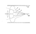
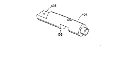
本発明で使用する代替ベルト400を、添付図面の図22〜24に見ることができる。このベルトは、図示の形状を形成するようにレーザ切断されたばね鋼の単一細片を備える。それにより、縁部が、容易に円滑になり、面取りすることができ、その結果、ベルトは、適切ないかなる面上でも円滑に走行することができる。
An
ベルトは、複数の駆動スロット401を備える。これらスロットは、ほぼ、ベルト400の長さに沿う直線で平行な両側部と、丸い両端部とを有するスロットの形態である。直線側部はそれぞれ、合致点に段差402を有し、その結果、段差402でスロットの幅が狭くなる。
The belt includes a plurality of
トラニオン403が各スロットに取り付けられ、1つだけが、図22に示されている。より詳細に図23aおよび23bに見ることができるように、トラニオンは、2つの切欠き部405を有する円筒形本体404を備える。ローラ408が本体404上に設けられている。両切欠き部は、スロット401の広い方の部分に隣接するベルトの金属部分、すなわちスロットが作られた後に残ったベルトの部分と同じ幅である。
A
トラニオンは、スロットの広い方の部分に、しかし段差に直ぐ隣接して、図23aに示すように取り付けられる。トラニオンがベルト上に配置されると、固定部406(1つだけ図示されている)を切欠き部に嵌め込んで本体404と固定部406との間にベルトを挟み込むことができ、次いで、その3つの物品をピン407によって固定することができる。
The trunnion is attached as shown in FIG. 23a to the wider part of the slot, but immediately adjacent to the step. When the trunnion is placed on the belt, the fixing portion 406 (only one is shown) can be fitted into the notch, and the belt can be sandwiched between the
このベルトは、添付図面の図24aおよび24bに示される駆動ホイール410と共に使用することができる。このホイール410は、前述の実施形態のような窪み411を有して、トラニオン403のローラ408を係合する。ホイールはまた、確実に、ベルト400をホイール410に対して正確に配置してトラニオン403を窪み411に係合させるために、スロット401の狭い部分に係合する硬化鋼案内スタッド412を有する。
This belt can be used with the
トラニオン403が窪み411内に入れば、駆動ホイールは、ベルト400を動かすためにベルトに力を加えることができる。切欠き部405の幅によって、この力が、トラニオンを通してベルトへ、段差402を用いて伝達される。これは、たとえばピン407に頼るよりも信頼性が高い。
Once the
Claims (13)
実質的に非伸張性であるが弾性的に可撓であり、長さ方向に強固に互いに固定されてエンドレス・ベルトを形成する少なくとも1つの平らな細片を備え、
一定の間隔で配置された駆動スロットを備え、
前記駆動スロットの各々は、段差がある外周を有し、
前記コンベヤが、前記ベルト沿いに間隔をおいて前記ベルトに固定された複数のトラニオンを備え、
各トラニオンが、前記駆動スロットに取り付けられており、
前記駆動スロットに前記段差が配置されることによって、前記トラニオンが前記ベルトの前記長さに沿った方向で力を加えられると、前記トラニオンが付勢力を前記段差を通じて前記ベルトに伝える
ことを特徴とするベルト。 A belt forming a conveyor or transmission belt,
Comprising at least one flat strip that is substantially non-stretchable but elastically flexible and is firmly fixed to one another in length to form an endless belt;
With drive slots arranged at regular intervals,
Each of said driving slot, have a periphery which is stepped,
The conveyor comprises a plurality of trunnions secured to the belt at intervals along the belt;
Each trunnion is mounted in the drive slot;
By arranging the step in the driving slot, the trunnion transmits a biasing force to the belt through the step when the trunnion is applied in a direction along the length of the belt. A belt characterized by that.
前記円筒形本体の軸が、前記ベルトの長さに対して直角をなすが、前記細片または各細片の面内にあることを特徴とする請求項1に記載のベルト。The belt according to claim 1, wherein the axis of the cylindrical body is perpendicular to the length of the belt but in the plane of the strip or each strip.
前記ホイールが、前記ベルトに沿う前記トラニオンと同じ間隔でその外周周りに離間配置された窪みを有する少なくとも1つの略円形のスプロケットを備えることを特徴とする請求項1から請求項3までのいずれか1項に記載のベルト。4. The wheel according to claim 1, wherein the wheel comprises at least one substantially circular sprocket having indentations spaced about its outer periphery at the same spacing as the trunnion along the belt. The belt according to item 1.
前記コンベヤが、前記コンベヤが動くと前記カムが追従するカム面を備え、それによって前記ベルトまたは各ベルトに対する前記搬送器の向きを制御することを特徴とする請求項7又は請求項8に記載のベルト。9. The conveyor of claim 7 or 8, wherein the conveyor comprises a cam surface that the cam follows as the conveyor moves, thereby controlling the orientation of the conveyor relative to the belt or each belt. belt.
Applications Claiming Priority (3)
| Application Number | Priority Date | Filing Date | Title |
|---|---|---|---|
| GBGB0717231.5A GB0717231D0 (en) | 2007-09-05 | 2007-09-05 | Conveyors |
| GB0717231.5 | 2007-09-05 | ||
| PCT/GB2008/002998 WO2009030913A2 (en) | 2007-09-05 | 2008-09-05 | Conveyors and transmission belts |
Publications (3)
| Publication Number | Publication Date |
|---|---|
| JP2010537921A JP2010537921A (en) | 2010-12-09 |
| JP2010537921A5 JP2010537921A5 (en) | 2011-10-06 |
| JP5496891B2 true JP5496891B2 (en) | 2014-05-21 |
Family
ID=38640247
Family Applications (1)
| Application Number | Title | Priority Date | Filing Date |
|---|---|---|---|
| JP2010523584A Expired - Fee Related JP5496891B2 (en) | 2007-09-05 | 2008-09-05 | Conveyor and transmission belt |
Country Status (9)
| Country | Link |
|---|---|
| US (1) | US8689969B2 (en) |
| EP (1) | EP2195264B1 (en) |
| JP (1) | JP5496891B2 (en) |
| CN (1) | CN101835699B (en) |
| AU (1) | AU2008294561B2 (en) |
| CA (1) | CA2736028A1 (en) |
| ES (1) | ES2409555T3 (en) |
| GB (1) | GB0717231D0 (en) |
| WO (1) | WO2009030913A2 (en) |
Families Citing this family (6)
| Publication number | Priority date | Publication date | Assignee | Title |
|---|---|---|---|---|
| AU2011239765A1 (en) * | 2010-04-13 | 2012-11-29 | George Terah Gough | Conveyor |
| GB201007399D0 (en) | 2010-05-04 | 2010-06-16 | Gough George T | Conveyors and transmission belts |
| WO2013010558A1 (en) * | 2011-07-19 | 2013-01-24 | Transnorm System Gmbh | Curved belt conveyor and chain for the said conveyor |
| CN103350863A (en) * | 2013-07-04 | 2013-10-16 | 大连佳林设备制造有限公司 | Vertical-type scrap iron scraper conveyor |
| CN109110387A (en) * | 2018-08-14 | 2019-01-01 | 徐州恒伟纸制品包装有限公司 | A kind of packaging steel conveyer belt |
| CN117233000B (en) * | 2023-11-14 | 2024-03-08 | 河南国智工程管理有限公司 | Semi-automatic impact testing machine |
Family Cites Families (24)
| Publication number | Priority date | Publication date | Assignee | Title |
|---|---|---|---|---|
| DE363894C (en) | 1921-08-23 | 1922-11-14 | Joseph Willemann | Steel conveyor belt made of several parallel longitudinal strips |
| US1508481A (en) | 1923-08-18 | 1924-09-16 | Sonesson August Erland | Metal belt |
| US2646161A (en) | 1950-09-29 | 1953-07-21 | United States Steel Corp | Transversely slotted metal belt for conveying and guiding strip traveling at high speed |
| US3728066A (en) | 1970-11-30 | 1973-04-17 | Vmw Ranshofen Berndorf Ag | Joint for endless belts |
| US3772930A (en) * | 1971-12-22 | 1973-11-20 | Caterpillar Tractor Co | Metal belt drive |
| US3851536A (en) * | 1973-02-16 | 1974-12-03 | Rockwell International Corp | Power transmission belt |
| DE2655487A1 (en) * | 1976-12-08 | 1978-06-15 | Zinser Textilmaschinen Gmbh | Conveyor belt with trunnions holding sleeves or spools upright - esp. for automatic sleeve changing mechanism in textile spinning or twisting machine |
| US4267921A (en) * | 1978-09-21 | 1981-05-19 | The Goodyear Tire & Rubber Company | Anti-backbend belts |
| US4890722A (en) | 1985-07-26 | 1990-01-02 | Refac International, Limited | Method and apparatus for conveying materials |
| JPH0752088Y2 (en) | 1988-12-29 | 1995-11-29 | トキワ工業株式会社 | Conveyor belt structure |
| CN2050415U (en) * | 1989-06-19 | 1990-01-03 | 陈文生 | Refractory conveying band and driving device |
| US5037359A (en) | 1989-06-30 | 1991-08-06 | U.S. Philips Corporation | Transmission system, motor drive comprising such a transmission system and wheel and belt for such a transmission system or motor drive |
| US4946028A (en) | 1989-07-26 | 1990-08-07 | Eichmann Harry A | Conveyor belt treatment |
| DE4244760C2 (en) | 1992-07-17 | 1994-11-03 | Scholtz Conrad Gmbh | Pocket conveyor |
| JPH06286843A (en) | 1993-03-31 | 1994-10-11 | Sharp Corp | Conveyor |
| CH687560A5 (en) | 1993-04-21 | 1996-12-31 | Hans Zeller | Drive assembly. |
| JPH0683617U (en) * | 1993-05-19 | 1994-11-29 | 株式会社フジテツモーテクニカルサービス | Belt for net conveyor |
| CN2190101Y (en) * | 1994-02-21 | 1995-02-22 | 赵振永 | Conveyer with cast crawlers |
| US6164432A (en) * | 1998-11-17 | 2000-12-26 | Roberts Polypro, Inc. | Apparatus for feeding articles |
| FI111100B (en) | 2000-01-31 | 2003-05-30 | Outokumpu Oy | Bands for continuous heat treatment of a material layer |
| ITBO20010370A1 (en) | 2001-06-12 | 2002-12-12 | Ima Spa | DEVICE FOR THE REMOVABLE COUPLING TO A METALLIC BELT CONVEYOR OF HOUSING FOR CONTAINERS |
| DE102004008165A1 (en) | 2004-02-10 | 2005-08-25 | Ekkehard Rath | Metal cog belt has square or circular apertures in its surface and is made by welding ends of strip together |
| US7191894B2 (en) | 2005-04-04 | 2007-03-20 | Laitram, L.L.C. | Variable angled-roller belt and conveyor |
| FI117982B (en) | 2006-01-20 | 2007-05-15 | Metso Paper Inc | Metal belt manufacture for use in paper/board machine or in finishing machine, includes placing metal belt blanks narrower than final belt width side-by-side and/or in succession, and welding joints by friction welding |
-
2007
- 2007-09-05 GB GBGB0717231.5A patent/GB0717231D0/en not_active Ceased
-
2008
- 2008-09-05 JP JP2010523584A patent/JP5496891B2/en not_active Expired - Fee Related
- 2008-09-05 AU AU2008294561A patent/AU2008294561B2/en not_active Expired - Fee Related
- 2008-09-05 CA CA2736028A patent/CA2736028A1/en not_active Abandoned
- 2008-09-05 CN CN200880112666.9A patent/CN101835699B/en not_active Expired - Fee Related
- 2008-09-05 ES ES08806203T patent/ES2409555T3/en active Active
- 2008-09-05 WO PCT/GB2008/002998 patent/WO2009030913A2/en active Application Filing
- 2008-09-05 EP EP08806203A patent/EP2195264B1/en not_active Not-in-force
- 2008-09-05 US US12/676,657 patent/US8689969B2/en active Active
Also Published As
| Publication number | Publication date |
|---|---|
| EP2195264A2 (en) | 2010-06-16 |
| GB0717231D0 (en) | 2007-10-17 |
| US8689969B2 (en) | 2014-04-08 |
| US20110048901A1 (en) | 2011-03-03 |
| EP2195264B1 (en) | 2013-01-16 |
| AU2008294561A1 (en) | 2009-03-12 |
| WO2009030913A2 (en) | 2009-03-12 |
| ES2409555T3 (en) | 2013-06-27 |
| WO2009030913A3 (en) | 2009-06-04 |
| CA2736028A1 (en) | 2009-03-12 |
| CN101835699A (en) | 2010-09-15 |
| JP2010537921A (en) | 2010-12-09 |
| AU2008294561B2 (en) | 2014-01-16 |
| CN101835699B (en) | 2014-12-24 |
Similar Documents
| Publication | Publication Date | Title |
|---|---|---|
| JP5496891B2 (en) | Conveyor and transmission belt | |
| US9555972B2 (en) | Conveyor belt and belt constituent members | |
| US7762388B2 (en) | Belt of a chain conveyor with innovative drive links | |
| US8991593B2 (en) | Chain conveyor | |
| EP2165948B1 (en) | Link for a modular conveyor belt with a transverse belt | |
| JPH11208859A (en) | Conveying system | |
| JP2018513078A (en) | Conveyor system with transfer belt | |
| JP2013506610A (en) | Belt conveyor with modular intermediate drive belt | |
| EP1663820B1 (en) | Modular conveyor belt and module for such a belt | |
| JPH0729683B2 (en) | Handling device with conveyor belt | |
| US9162829B2 (en) | Conveyor | |
| US20050109579A1 (en) | Pallet conveyor | |
| JP2006111394A (en) | Bucket conveyor | |
| NL1026601C2 (en) | Conveyor belt comprising elastic and rigid parts, has pivoting spacers provided between these belt parts | |
| JP2004189416A (en) | Conveyer belt | |
| JP3834518B2 (en) | Transport device | |
| NL1028857C2 (en) | Conveyor with belt comprising rigid sections, eliminates play between these sections using belt length correction device | |
| WO2007092882A2 (en) | Conveyor with edge guides | |
| NL1031667C2 (en) | Endless conveyor belt comprising rigid sections, has belt length correction device for eliminating play between these sections | |
| NL1034765C1 (en) | Conveyor belt comprising rigid elements, has means for absorbing and dissipating transport force before and after bends | |
| JP2019202849A (en) | Bucket conveyor |
Legal Events
| Date | Code | Title | Description |
|---|---|---|---|
| A521 | Written amendment |
Free format text: JAPANESE INTERMEDIATE CODE: A523 Effective date: 20110816 |
|
| A621 | Written request for application examination |
Free format text: JAPANESE INTERMEDIATE CODE: A621 Effective date: 20110816 |
|
| A977 | Report on retrieval |
Free format text: JAPANESE INTERMEDIATE CODE: A971007 Effective date: 20130419 |
|
| A131 | Notification of reasons for refusal |
Free format text: JAPANESE INTERMEDIATE CODE: A131 Effective date: 20130430 |
|
| A601 | Written request for extension of time |
Free format text: JAPANESE INTERMEDIATE CODE: A601 Effective date: 20130729 |
|
| A602 | Written permission of extension of time |
Free format text: JAPANESE INTERMEDIATE CODE: A602 Effective date: 20130805 |
|
| A601 | Written request for extension of time |
Free format text: JAPANESE INTERMEDIATE CODE: A601 Effective date: 20130820 |
|
| A602 | Written permission of extension of time |
Free format text: JAPANESE INTERMEDIATE CODE: A602 Effective date: 20130827 |
|
| A521 | Written amendment |
Free format text: JAPANESE INTERMEDIATE CODE: A523 Effective date: 20131024 |
|
| TRDD | Decision of grant or rejection written | ||
| A01 | Written decision to grant a patent or to grant a registration (utility model) |
Free format text: JAPANESE INTERMEDIATE CODE: A01 Effective date: 20140204 |
|
| A61 | First payment of annual fees (during grant procedure) |
Free format text: JAPANESE INTERMEDIATE CODE: A61 Effective date: 20140305 |
|
| R150 | Certificate of patent or registration of utility model |
Ref document number: 5496891 Country of ref document: JP Free format text: JAPANESE INTERMEDIATE CODE: R150 |
|
| LAPS | Cancellation because of no payment of annual fees |