JP5494183B2 - Automatic harvesting equipment - Google Patents
Automatic harvesting equipment Download PDFInfo
- Publication number
- JP5494183B2 JP5494183B2 JP2010100009A JP2010100009A JP5494183B2 JP 5494183 B2 JP5494183 B2 JP 5494183B2 JP 2010100009 A JP2010100009 A JP 2010100009A JP 2010100009 A JP2010100009 A JP 2010100009A JP 5494183 B2 JP5494183 B2 JP 5494183B2
- Authority
- JP
- Japan
- Prior art keywords
- fruit
- photographing
- crop
- automatic harvesting
- image processing
- Prior art date
- Legal status (The legal status is an assumption and is not a legal conclusion. Google has not performed a legal analysis and makes no representation as to the accuracy of the status listed.)
- Active
Links
Images


Description
本発明は、野菜や果物等の果実の収穫を自動的に行う自動収穫装置に関する。 The present invention relates to an automatic harvesting apparatus that automatically harvests fruits such as vegetables and fruits.
近年、画像処理技術やロボット技術等の進展に伴って、果実の収穫を自動的に行う自動収穫装置の開発が盛んに行われている。現在、農業従事者の高齢化が深刻な問題となっており、今後も就農人口が減少傾向にあることから、少ない人手で効率的に果実を収穫することができる自動収穫装置の期待が高まっている。また、近年では、果実の安定供給のために、閉鎖的又は半閉鎖的な空間内で植物を計画的に生産する植物工場の稼働が始まっている。このような植物工場においても、省力化等のために自動収穫装置が用いられている。 In recent years, with the progress of image processing technology, robot technology, and the like, automatic harvesting devices that automatically harvest fruits have been actively developed. At present, the aging of farmers has become a serious problem, and since the farming population is decreasing, the expectation of an automatic harvesting device that can efficiently harvest fruits with fewer human resources is increasing. Yes. In recent years, a plant factory that systematically produces plants in a closed or semi-closed space has started to stably supply fruits. Even in such a plant factory, an automatic harvesting apparatus is used for labor saving and the like.
以下の特許文献1には、CCD(Charge Coupled Device:電荷結合素子)カメラによる2位置ステレオ撮像を行って果実(キュウリ)までの距離を的確に検出し、果実の収穫量を向上させる自動収穫装置が開示されている。具体的には、CCDカメラをスライドさせる前に撮像した第1画像における果実の位置が、画像面の中心線から左右側に偏位した位置にあれば、CCDカメラをその偏位している側へスライドして第2画像を撮影し、これら第1,第2画像に基づいて果実までの距離を検出している。
The following
ところで、自動収穫装置は、基本的にはCCDカメラ等を用いて得られた画像に基づいて収穫すべき果実を検出し、その検出結果に基づいて果実の収穫を行うものである。このため、従来の自動収穫装置は、一定方向に集中して生っている果実や葉等に隠れていない果実であれば自動的に収穫が可能であるものの、生っている方向がバラバラな果実や葉等に隠れた果実の収穫は困難であった。 By the way, the automatic harvesting apparatus basically detects a fruit to be harvested based on an image obtained using a CCD camera or the like, and harvests the fruit based on the detection result. For this reason, the conventional automatic harvesting device can automatically harvest fruits that are concentrated in a certain direction or fruits that are not hidden in the leaves, but the direction in which they are grown varies. It was difficult to harvest fruits hidden behind fruits and leaves.
従って、従来は、自動収穫装置にて収穫すべき果実が葉等に隠れず、且つ一定方向に集中するように、果実の栽培方法を工夫する必要があった。例えば、上記の特許文献1では、ツタが絡まる支柱を自動収穫装置の走行路に向けて傾けた状態でキュウリを栽培することにより、収穫すべき果実であるキュウリの実が葉に隠れず、且つ上下方向を向くようにしている。
Therefore, conventionally, it has been necessary to devise a fruit cultivation method so that the fruits to be harvested by the automatic harvesting apparatus are not hidden by the leaves and concentrated in a certain direction. For example, in the above-mentioned
しかしながら、自動収穫装置で収穫すべき果実は、キュウリのような棒状の形状であって空中にぶら下がった状態で生るものばかりではない。例えば、リンゴや柿のような球体形状であって枝になるものもあれば、イチゴのような略円錐形状であって地表に生るものもある。このため、果実の栽培方法を工夫しても自動収穫装置の目線からは果実が葉等に隠れてしまうことが考えられる。従来自動収穫装置では、このような果実の収穫を効率的に行うことができないという問題があった。 However, the fruit to be harvested by the automatic harvesting device is not only a cucumber-like rod-like shape that grows in the air hanging state. For example, some of them have a spherical shape like apples and strawberries and become branches, while others have a substantially conical shape like strawberries and grow on the ground. For this reason, even if it devises the cultivation method of a fruit, it is possible that a fruit hides in a leaf etc. from the viewpoint of an automatic harvesting apparatus. Conventional automatic harvesting devices have a problem that such fruits cannot be efficiently harvested.
本発明は、上記事情に鑑みてなされたものであり、葉等に隠れた状態の果実であっても自動的に収穫することができる自動収穫装置を提供することを目的とする。 This invention is made | formed in view of the said situation, and it aims at providing the automatic harvesting apparatus which can be automatically harvested even if it is the fruit of the state hidden in the leaf.
上記課題を解決するために、本発明の自動収穫装置は、収穫すべき果実が生る農作物を撮影する撮影装置(15)と、前記撮影装置で撮影された画像から特定される前記果実を収穫する収穫装置(14)とを備える自動収穫装置(1〜3)において、前記撮影装置によって撮影が行われている状態で、前記農作物の葉を揺動させる揺動装置(12、14)と、前記揺動装置が前記農作物の葉を揺動させているときに前記撮影装置で撮影される複数の画像に対して所定の画像処理を行い、前記葉に隠れた前記果実を特定する画像処理装置(C11、C21)とを備えることを特徴としている。
また、本発明の自動収穫装置は、前記揺動装置が、前記農作物に向けた送風を行うことにより、前記農作物の葉を揺動させる送風装置(12)であることを特徴としている。
また、本発明の自動収穫装置は、前記送風装置の位置又は姿勢の少なくとも一方を制御して、前記農作物に向けた送風を異なる方向から行わせる駆動制御装置(C12)を備えることを特徴としている。
また、本発明の自動収穫装置は、前記揺動装置が、前記農作物の一部を把持して振動させることにより、前記農作物の葉を揺動させることを特徴としている。
また、本発明の自動収穫装置は、前記収穫装置が、収穫すべき果実を把持するとともに、前記揺動装置を兼ねることを特徴としている。
また、本発明の自動収穫装置は、前記揺動装置が、前記農作物に取り付けられて前記農作物を振動させる振動装置(32)に対して振動の開始及び停止を指示することにより、前記農作物の葉を揺動させることを特徴としている。
また、本発明の自動収穫装置は、前記画像処理装置が、前記撮影装置で撮影される複数の画像を積算する処理を行い、積算値の大きな部分を前記果実と特定することを特徴としている。
また、本発明の自動収穫装置は、前記画像処理装置が、前記撮影装置で撮影される複数の画像の変化部分毎の周波数分析を行い、周波数が低い部分を前記果実と特定することを特徴としている。
In order to solve the above-mentioned problems, an automatic harvesting apparatus of the present invention harvests the fruit specified by an image capturing device (15) that captures a crop from which a fruit to be harvested grows, and an image captured by the image capturing device. In an automatic harvesting device (1-3) comprising a harvesting device (14), a swinging device (12, 14) for swinging the leaves of the crop in a state where photographing is performed by the photographing device; An image processing device that performs predetermined image processing on a plurality of images photographed by the photographing device when the rocking device is rocking the leaves of the crop, and identifies the fruit hidden in the leaves (C11, C21).
Moreover, the automatic harvesting apparatus of the present invention is characterized in that the swing device is a blower device (12) that swings the leaves of the crop by blowing air toward the crop.
Moreover, the automatic harvesting apparatus of the present invention is characterized by including a drive control device (C12) that controls at least one of the position or posture of the blower device and blows air toward the farm products from different directions. .
Moreover, the automatic harvesting apparatus of the present invention is characterized in that the swinging device swings the leaves of the crop by gripping and vibrating a part of the crop.
Moreover, the automatic harvesting device of the present invention is characterized in that the harvesting device holds a fruit to be harvested and also serves as the swinging device.
Further, in the automatic harvesting apparatus of the present invention, the swinging device instructs the vibration device (32) attached to the crop to vibrate the crop to start and stop the vibration, thereby Is characterized by swinging.
The automatic harvesting apparatus of the present invention is characterized in that the image processing apparatus performs a process of integrating a plurality of images photographed by the photographing apparatus, and identifies a portion having a large integrated value as the fruit.
In the automatic harvesting device of the present invention, the image processing device performs frequency analysis for each changed portion of a plurality of images photographed by the photographing device, and identifies a portion having a low frequency as the fruit. Yes.
本発明によれば、振動装置によって農作物の葉を揺動させつつ撮影装置で農作物を撮影し、撮影装置で撮影される複数の画像に対して所定の画像処理を行って葉に隠れた果実を特定しているため、葉等に隠れた状態の果実であっても自動的に収穫することができるという効果がある。 According to the present invention, a crop is photographed by a photographing device while swinging a crop leaf by a vibration device, and a predetermined image processing is performed on a plurality of images photographed by the photographing device to remove a fruit hidden in the leaf. Since it is specified, there is an effect that even a fruit hidden in a leaf or the like can be automatically harvested.
以下、図面を参照して本発明の実施形態による自動収穫装置について詳細に説明する。尚、以下では、理解を容易にするために、農作物がリンゴの木であって収穫すべき果実がリンゴの実である場合を例に挙げて説明するが、本発明は他の野菜や果物の果実を収穫する自動収穫装置にも適用可能である。 Hereinafter, an automatic harvesting apparatus according to an embodiment of the present invention will be described in detail with reference to the drawings. In the following, in order to facilitate understanding, the case where the crop is an apple tree and the fruit to be harvested is an apple fruit will be described as an example. However, the present invention is not limited to other vegetables and fruits. It can also be applied to an automatic harvesting device that harvests fruits.
また、以下では、図中に設定したXYZ直交座標系を参照しつつ自動収穫装置が備える各部材の位置関係について説明する。このXYZ直交座標系は、XY平面が水平面に平行な面に設定されており、Z軸が鉛直上方向に設定されている。尚、自動収穫装置の進行方向はY方向であるものとし、農作物であるリンゴの木は自動収穫装置の走行経路の+X側に自動収穫装置の進行方向であるY方向に沿って植林されているとする。 Moreover, the positional relationship of each member with which an automatic harvesting apparatus is provided is demonstrated below, referring the XYZ rectangular coordinate system set in the figure. In this XYZ orthogonal coordinate system, the XY plane is set to a plane parallel to the horizontal plane, and the Z axis is set to the vertically upward direction. The traveling direction of the automatic harvesting device is assumed to be the Y direction, and the apple tree as a crop is planted along the Y direction, which is the traveling direction of the automatic harvesting device, on the + X side of the traveling path of the automatic harvesting device. And
〔第1実施形態〕
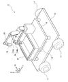
図1は、本発明の第1実施形態による自動収穫装置の外観を模式的に示す斜視図である。図1に示す通り、本実施形態の自動収穫装置1は、平面視形状が略矩形形状の車台10に支持される4つの車輪11と、車台10上に設けられる送風機12(揺動装置、送風装置)、送風機駆動機構13、マニピュレータ14(収穫装置)、画像センサ15(撮影装置)、収穫籠16、バッテリ17、及びコントローラ18とを備えており、車輪11によって走行しつつ、収穫すべき果実であるリンゴの実を自動的に収穫する。
[First Embodiment]
FIG. 1 is a perspective view schematically showing the external appearance of the automatic harvesting apparatus according to the first embodiment of the present invention. As shown in FIG. 1, the
4つの車輪11は、車台11の左右方向(±X方向)の前側(+Y側)及び後側(−Y側)にそれぞれ配設されており、モータ(図示省略)の動力によって駆動され、車台10の左右方向に沿う回転軸の周りで回転可能に車台10に支持されている。尚、車台11の左側に配設された車輪11と右側に配設された車輪11との駆動量を変えることにより自動収穫装置1の進行方向を変更することができる。
The four
送風機12は、車台11の右端側(+X側)に配設されており、例えば多翼ファンを回転させてリンゴの木に向けて送風を行う。この送風機12は、リンゴの木に向けた送風によってリンゴの木の葉を揺動させるために設けられる。送風機駆動機構13は、送風機12を下部から支持しており、コントローラ18の制御の下で送風機12の位置及び姿勢を変える機構である。
The
具体的に、送風機駆動機構13は、車台11の右端側に設けられたY方向に延びるレール13aに沿って移動可能に、且つZ方向に伸縮自在に構成されており、支持する送風機12の車台10上におけるY方向の位置及びZ方向の位置を変えることができる。また、送風機駆動機構13は、その上端部付近が図中のθ方向及びφ方向に回動可能に構成されており、Z軸及びY軸の周りで送風機12を首振りさせて送風機12の姿勢を変えることができる。
Specifically, the
マニピュレータ14は、複数の関節を有するアーム部14aと、アーム部14aの先端部に取り付けられたハンド部14bとを備える所謂ロボットアームであり、車台10の中央部に設けられた棚板19の上部に取り付けられている。このマニピュレータ14は、コントローラ18の制御の下で、画像センサ15で撮影された画像から特定されるリンゴの実をハンド部14bで把持して収穫する。尚、マニピュレータ14のアーム部14aの長さや関節数、及びハンド部14bの大きさや形状は、収穫すべき果実に応じて適宜変更が可能である。
The
画像センサ15は、例えばCCDカメラ等のカメラを備えており、収穫すべき果実であるリンゴの実が生るリンゴの木を撮影する。この画像センサ15は、マニピュレータ14のアーム部14aの先端にハンド部14bとともに取り付けられており、マニピュレータ14を操作することにより、画像センサ15によって撮影される位置及び角度を変えることが可能である。尚、詳細は後述するが、画像センサ15で撮影された画像は、コントローラ18で所定の画像処理が施されて収穫すべき果実であるリンゴの実が特定される。
The
収穫籠17は、マニピュレータ14によって収穫されたリンゴの実を収容する籠であり、棚板19の上部に設けられている。バッテリ17は、車台の後側に取り付けられたニッケル水素電池、リチウムイオン電池等の二次電池であり、車輪11、送風機12、送風機駆動機構13、マニピュレータ14、画像センサ15、及びコントローラ18を動作させるための電力を供給する。
The
コントローラ18は、自動収穫装置1の動作を統括して制御する。例えば、車輪11を駆動する不図示のモータの駆動量を制御して自動収穫装置1の走行制御を行う。また、マニピュレータ14を制御して画像センサ15によるリンゴの木の撮影位置を設定するとともに、画像センサ15で撮影された画像に対して所定の画像処理を行って収穫すべきリンゴの実を特定する。また、画像センサ15でリンゴの木を撮影するときに、送風機12及び送風機駆動機構13を制御してリンゴの木の葉を揺動させる。更に、マニピュレータ14を制御して、上記の画像処理によって特定されたリンゴの実を収穫させる。
The
図2は、本発明の第1実施形態による自動収穫装置の制御系の構成を示すブロック図である。尚、図2においては、図1に示した構成に相当するブロックについては、図1に示した符号と同じ符号を付している。また、図2中の走行機構Dは、自動収穫装置1を走行させる機構であって、図1に示した4つの車輪11とこれらを個別に駆動する付図視のモータからなる機構である。
FIG. 2 is a block diagram showing the configuration of the control system of the automatic harvesting apparatus according to the first embodiment of the present invention. In FIG. 2, blocks corresponding to the configuration shown in FIG. 1 are denoted by the same reference numerals as those shown in FIG. A traveling mechanism D in FIG. 2 is a mechanism that causes the
図2に示す通り、コントローラ18は、画像処理部C11(画像処理装置)、送風機駆動制御部C12(駆動制御装置)、アーム駆動制御部C13、及び走行制御部14を備えている。画像処理部C11は、画像センサ15で撮影された画像に対して所定の画像処理を行って収穫すべきリンゴの実を特定する。具体的には、画像センサ15で撮影された複数の画像を積算する処理(或いは、重ね合わせ処理)及びエッジ検出処理を行い、積算値の大きな部分であってリンゴの実の輪郭の形状に近似する部分をリンゴの実であると特定する。
As shown in FIG. 2, the
本実施形態では、リンゴの木を画像センサ15で撮影するときに、送風機12によってリンゴの木の葉を揺動させながら撮影してる。風が吹き付けられるとリンゴの木の葉は軽量であるため容易に揺動するのに対し、リンゴの実はその重みのために揺動しにくい。このため、画像センサ15で撮影される画像内におけるリンゴの実の位置は殆ど変わらないのに対し、リンゴの木の葉の位置は頻繁に変わる。このような性質を利用し、画像処理部C11は、画像の積算値の大きな部分であってリンゴの実の輪郭の形状に近似する部分をリンゴの実であると特定している。
In this embodiment, when the apple tree is photographed by the
送風機駆動制御部C12は、送風機駆動機構13を制御して、車台10上における送風機12のY方向の位置及びZ方向の位置、並びに送風機12のZ軸及びY軸の周りでの送風機12の首振り量を変える。送風機駆動制御部C12が送風機駆動機構13を制御して送風機12の位置及び首振り量を変えるのは、リンゴの木に向けた送風を異なる方向から行ってリンゴの木の葉の揺れ方を変えることにより、リンゴの木の実の検出精度を高めるためである。尚、送風機駆動制御部C12は、送風機12による送風の開始及び停止も制御する。
The blower drive control unit C12 controls the
アーム駆動制御部C13は、マニピュレータ14の動作を制御する。具体的に、アーム駆動制御部C13は、マニピュレータ14のアーム部14aに設けられている複数の間接の角度、及びアーム部14aのZ軸周りの回転量を制御することにより、ハンド部14b及び画像センサ15の位置及び姿勢を設定する。また、マニピュレータ14のハンド部14bを制御して、収穫すべきリンゴの実等を把持するか否かを制御する。
The arm drive control unit C13 controls the operation of the
走行制御部C14は、走行機構Dをなす不図示のモータ(車輪11を駆動するモータ)の駆動量を制御することにより、動収穫装置1の走行制御を行う。具体的に、4つの車輪11の回転速度及び回転方向を同じにして自動収穫装置1を+Y方向又は−Y方向に沿って移動させる。また、車台11の左側に配設された車輪11と右側に配設された車輪11との駆動量を変えて自動収穫装置1の進行方向を変更する。更には、車台11の左側に配設された車輪11と右側に配設された車輪11との回転方向を変えて自動収穫装置1を回転させる。
The traveling control unit C14 performs traveling control of the
次に、上記構成における自動収穫装置1の収穫時の動作について説明する。図3は、本発明の第1実施形態による自動収穫装置の収穫時の動作を示すフローチャートである。まず、コントローラ18の走行制御部C14が走行機構Dを制御して自動収穫装置1を走行させ、収穫すべきリンゴの実が生っているリンゴの木の近傍に自動収穫装置1を移動させる。
Next, the operation | movement at the time of harvesting of the
自動収穫装置1の移動が完了すると、コントローラ18のアーム駆動制御部C13がマニピュレータ14を制御し、マニピュレータ14のハンド部14b及び画像センサ15を対象物(リンゴの木)の近傍に移動させる(ステップS11)。ハンド部14b及び画像センサ15の移動が完了し、画像センサ15によって撮影すべき位置及び方向が設定されると、画像センサ15によってリンゴの木の撮影(計測)が開始され、画像センサ15からコントローラ18に対して撮影された画像の画像データが出力される(ステップS12)。尚、コントローラ18に出力された画像データは、画像処理部C11に記憶される。
When the movement of the
画像センサ15による撮影が開始されると、コントローラ18の送風機駆動制御部C12が送風機12を制御して、リンゴの木に対する送風を開始させる(ステップS13)。送風機12による送風が開始されると、送風機駆動制御部C12は送風機駆動機構13を制御して送風機12を駆動させる(ステップS14)。具体的には、送風機12をレール13aに沿ってY方向に移動させたり、送風機12をZ方向に移動させることによって送風機12の位置を変える。また、送風機駆動機構13の上端部付近をθ方向に回動させたり、φ方向に回動させることにより、送風機12を首振りさせて送風機12の姿勢を変える。
When shooting by the
次に、コントローラ18は、送風機駆動機構13による送風機12の駆動が完了したか否かを判断する(ステップS15)。例えば、送風機12がレール13aの一端から他端への移動の途中であって、送風機12の移動がが完了していない場合には、ステップS15の判断は「NO」になり、ステップS15の判断を繰り返す。これに対し、例えばレール13aの他端への移動が完了した場合には、ステップS15の判断は「YES」になり、送風機12による送風を停止して送風機12を初期位置(例えば、レール13aの一端)に移動させる制御が送風機駆動制御部C12によって行われ(ステップS16)、画像センサ15によるリンゴの木の撮影(計測)が終了する(ステップS17)。
Next, the
以上の処理が完了すると、画像処理部C11は、記憶した画像データに対して所定の画像処理を行って実と葉とを区分けする(ステップS18)。具体的には、画像データを積算するとともにエッジを検出し、積算値の大きな部分であってリンゴの実の輪郭の形状に近似する部分を抽出してリンゴの実を特定する。画像処理部C11によってリンゴの実が特定されると、アーム駆動制御部C13によってマニピュレータ14が制御され、特定されたリンゴの実がマニピュレータ14のハンド部14bに把持されて収穫籠17に収穫される(ステップS19)。
When the above processing is completed, the image processing unit C11 performs predetermined image processing on the stored image data and classifies fruits and leaves (step S18). Specifically, the image data is integrated and the edge is detected, and the part having a large integrated value that approximates the shape of the outline of the apple fruit is extracted to specify the fruit of the apple. When the fruit of the apple is specified by the image processing unit C11, the
尚、複数のリンゴの実が特定された場合には、マニピュレータ14によって順次収穫される。また、収穫すべきリンゴの実が生っているリンゴの木が他にもある場合には、コントローラ18の走行制御部C14によって走行機構Dが制御され、次のリンゴの木の近傍への自動収穫装置1の移動が行われる。そして、図3に示す処理が行われて、そのリンゴの木に生っているリンゴの実の収穫が同様に行われる。
When a plurality of apple fruits are specified, they are sequentially harvested by the
また、以上の説明では、画像センサ15によって撮影される位置及び方向が固定された状態でリンゴの木が撮影される例について説明したが、画像センサ15によって撮影される位置は固定しつつ、撮影される方向を変えても良い。また、以上では、画像センサ15による撮影が行われている間に、送風機駆動機構13によって送風機12が駆動(位置の移動及び首振り)される例について説明したが、必要がなければ送風機12の駆動は省略してもい。
In the above description, the example in which the apple tree is photographed in a state where the position and direction photographed by the
〔第2実施形態〕
図4は、本発明の第2実施形態による自動収穫装置の外観を模式的に示す斜視図である。尚、図4においては、図1に示した構成と同じものについては同一の符号を付してある。図4に示す通り、本実施形態の自動収穫装置2は、図1に示す自動収穫装置1が備える送風機12、送風機駆動機構13、及びレール13aを省略し、ハンド部14bとは別個に画像センサ15を移動させることができるサブアーム21をマニピュレータ14に取り付けた構成である。
[Second Embodiment]
FIG. 4 is a perspective view schematically showing the appearance of the automatic harvesting apparatus according to the second embodiment of the present invention. In FIG. 4, the same components as those shown in FIG. As shown in FIG. 4, the
以上の構成の自動収穫装置2は、リンゴの木の一部(例えば、リンゴの木の枝や幹)をマニピュレータ14のハンド部14bで把持して震動させることにより、リンゴの木の葉を揺動させるものである。このように、本実施形態では、マニピュレータ14を、リンゴの実を収穫する収穫装置として用いるだけではなく、リンゴの木の葉を揺動させる揺動装置として用いている。
The
ここで、前述した第1実施形態の自動収穫装置1のように、画像センサ15がハンド部14bとともにマニピュレータ14のアーム部14aの先端に取り付けられていたのでは、ハンド部14bを震動させる度に画像センサ15も震動してしまい、撮影位置及び撮影方向が定まらない。このため、本実施形態では、先端に画像センサ15が取り付けられたサブアーム21をマニピュレータ14に取り付け、ハンド部14bと画像センサ15とを別個に移動可能にしている。これにより、ハンド部14bを震動させた場合であっても、画像センサ15によって撮影される位置及び方向を固定することができる。
Here, when the
図5は、本発明の第2実施形態による自動収穫装置の制御系の構成を示すブロック図である。尚、図5においては、図2に示したブロックと同じブロックについては同一の符号を付している。図5に示す通り、本実施形態において、コントローラ18は、画像処理部C21(画像処理装置)、アーム駆動制御部C22、及び走行制御部14を備える構成である。つまり、図5に示すコントローラ18は、図2に示すコントローラの送風機駆動制御部C12を省略し、画像処理部C11及びアーム駆動制御部C12に代えて画像処理部C21及びアーム駆動制御部C22を設けた構成である。
FIG. 5 is a block diagram showing the configuration of the control system of the automatic harvesting apparatus according to the second embodiment of the present invention. In FIG. 5, the same blocks as those shown in FIG. 2 are denoted by the same reference numerals. As shown in FIG. 5, in the present embodiment, the
画像処理部C21は、画像センサ15で撮影された画像に対して所定の画像処理を行って収穫すべきリンゴの実を特定する。具体的には、画像センサ15で撮影された複数の画像の変化部分毎の周波数分析を行い、周波数が低い部分をリンゴの実であると特定する。ここで、リンゴの木の枝等をマニピュレータ14のハンド部14bで把持して震動させたときに、リンゴの木の葉は容易に揺動するのに対し、リンゴの実はその重みのために揺動しにくい。従って、リンゴの実が揺動する周波数はリンゴの木の葉が揺動する周波数よりも低い傾向がある。このような性質を利用し、画像処理部C21は、画像センサ15で撮影された複数の画像の変化部分毎の周波数分析を行い、周波数が低い部分をリンゴの実であると特定している。
The image processing unit C21 performs predetermined image processing on the image photographed by the
アーム駆動制御部C22は、サブアーム21が取り付けられたマニピュレータ14の動作を制御する。具体的に、アーム駆動制御部C22は、図2に示すアーム駆動制御部C13と同様に、マニピュレータ14のアーム部14aに設けられている複数の間接の角度、及びアーム部14aのZ軸周りの回転量を制御することにより、ハンド部14bの位置及び姿勢を設定する。また、マニピュレータ14のハンド部14bを制御して、収穫すべきリンゴの実等を把持するか否かを制御する。これらの制御に加えて、アーム駆動制御部C22は、アブアーム21の関節の角度等を制御することにより、サブアーム21の先端に取り付けられている画像センサ15の位置及び姿勢を設定する。
The arm drive control unit C22 controls the operation of the
次に、上記構成における自動収穫装置2の収穫時の動作について説明する。図6は、本発明の第2実施形態による自動収穫装置の収穫時の動作を示すフローチャートである。まず、第1実施形態と同様に、コントローラ18の走行制御部C14が走行機構Dを制御して自動収穫装置2を走行させ、収穫すべきリンゴの実が生っているリンゴの木の近傍に自動収穫装置2を移動させる。
Next, the operation | movement at the time of harvesting of the
自動収穫装置2の移動が完了すると、コントローラ18のアーム駆動制御部C22がマニピュレータ14を制御し、サブアーム21の先端に取り付けられている画像センサ15を対象物(リンゴの木)の近傍に移動させる(ステップS21)。具体的には、リンゴの木から1〜5m程度離間した位置に画像センサ15を移動させる。画像センサ15の移動が完了し、画像センサ15によって撮影すべき位置及び方向が設定されると、画像センサ15によってリンゴの木の撮影(計測)が開始され、画像センサ15からコントローラ18に対して撮影された画像の画像データが出力される(ステップS22)。尚、コントローラ18に出力された画像データは、画像処理部C21に記憶される。
When the movement of the
画像センサ15による撮影が開始されると、コントローラ18のアーム駆動制御部C22は、マニピュレータ14を制御してハンド部14bによってリンゴの木の一部(例えば、リンゴの木の茎)を把持させ(ステップS23)、ハンド部14bを一定周期で振動させる(ステップS24)。これにより、リンゴの木のハンド部14bに把持された部分が振動してリンゴの木の葉が揺動する。尚、ハンド部14bが振動している間は、サブアーム21の先端に取り付けられている画像センサ15の位置及び姿勢は固定されたままである。
When shooting by the
以上の動作が継続されると、リンゴの木の一部が振動している状態で画像センサ15で撮影された複数の画像データが画像処理部C21に記憶される。画像処理部C21は、記憶された画像データを用いて周波数分析を行う(ステップS25)。具体的には、画像センサ15で撮影された複数の画像の変化部分毎の周波数分析を行い、周波数が低い部分をリンゴの実であると特定する。
When the above operation is continued, a plurality of image data photographed by the
次に、コントローラ18は、画像処理部C21によってリンゴの実の位置が検出された否かを判断する(ステップS26)。画像処理部C21でリンゴの実の位置が検出されなかった場合にはステップS26の判断結果は「NO」になり、コントローラ18は、アーム駆動制御部C22に対してマニピュレータ14の振動周期(ハンド部14bの振動周期)を変更させる(ステップS27)。そして、新たに設定された振動周期でハンド部14bを振動させてリンゴの木の撮影を行い(ステップS24)、新たに得られた画像データを用いた周波数分析が行われる(ステップS25)。
Next, the
これに対し、画像処理部C21でリンゴの実の位置が検出された場合にはステップS26の判断結果は「YES」になる。すると、コントローラ18はアーム駆動制御部C22に対して検出されたリンゴの実を収穫させる指示を行う。かかる指示がなされると、アーム駆動制御部C22によってマニピュレータ14が制御され、特定されたリンゴの実がマニピュレータ14のハンド部14bに把持されて収穫籠17に収穫される(ステップS28)。
On the other hand, when the actual position of the apple is detected by the image processing unit C21, the determination result in step S26 is “YES”. Then, the
尚、第1実施形態と同様に、複数のリンゴの実が特定された場合には、マニピュレータ14によって順次収穫される。また、収穫すべきリンゴの実が生っているリンゴの木が他にもある場合には、コントローラ18の走行制御部C14によって走行機構Dが制御され、次のリンゴの木の近傍への自動収穫装置2の移動が行われる。そして、図6に示す処理が行われて、そのリンゴの木に生っているリンゴの実の収穫が同様に行われる。
As in the first embodiment, when a plurality of apple fruits are specified, they are sequentially harvested by the
ここで、前述したサブアーム21は、ハンド部14bと画像センサ15とが別個に移動可能であれば、マニピュレータ14の任意の位置に取り付けられていて良い。また、画像センサ15を移動させる機構(サブアーム21)は、必ずしもマニピュレータ14に取り付けられている必要はなく、図7に示す通り、マニピュレータ14とは別個に設けられていても良い。
Here, the
図7は、本発明の第2実施形態による自動収穫装置の変形例を模式的に示す斜視図である。図7に示す自動収穫装置2は、2つのマニピュレータ14,21を備えている。マニピュレータ14は、複数の関節を有するアーム部14aと、アーム部14aの先端部に取り付けられたハンド部14bとを備えている。これに対し、マニピュレータ21は、アーム部14aと同様の複数の関節を有するアーム部からなり、その先端部に画像センサ15が取り付けられている。図7に示す構成にしても、ハンド部14bと画像センサ15とを別個に移動させることができるため、ハンド部14bによってリンゴの木の一部を振動させながら画像センサ15による撮影を行うことができる。
FIG. 7 is a perspective view schematically showing a modification of the automatic harvesting apparatus according to the second embodiment of the present invention. The
〔第3実施形態〕
図8は、本発明の第3実施形態による自動収穫装置の外観を模式的に示す斜視図である。尚、図8においては、図1に示した構成と同じものについては同一の符号を付してある。図8に示す通り、本実施形態の自動収穫装置3は、図1に示す自動収穫装置1が備える送風機12、送風機駆動機構13、及びレール13aを省略し、車台10の右端に振動コマンド送信機31を設けた構成である。
[Third Embodiment]
FIG. 8 is a perspective view schematically showing the appearance of the automatic harvesting apparatus according to the third embodiment of the present invention. In FIG. 8, the same components as those shown in FIG. 1 are denoted by the same reference numerals. As shown in FIG. 8, the
本実施形態の自動収穫装置3は、予めリンゴの木Trに取り付けられた振動装置32に対して振動コマンドを送信して振動装置32の振動の開始及び停止を指示することにより、リンゴの木の葉を揺動させるものである。つまり、本実施形態の自動収穫装置3は、リンゴの木Trの一部を振動させるための振動機構は備えておらず、外部に設けられた振動機構(振動装置32)を振動させるものである。
The
振動コマンド送信機31は、コントローラ18の制御の下で振動装置32を振動させるための振動コマンドを送信する機器であり、例えば電波や赤外線等を用いて振動コマンドを送信する。振動装置32は、例えばリンゴの木Trの幹に取り付けられており、振動コマンド送信機31から振動コマンドが送信された場合に、リンゴの木Trの幹を振動させることによって、リンゴの木の葉を揺動させるものである。
The
図9は、本発明の第3実施形態による自動収穫装置の制御系の構成を示すブロック図である。尚、図9においては、図2又は図5に示したブロックと同じブロックについては同一の符号を付している。図9に示す通り、本実施形態において、コントローラ18は、画像処理部C21、振動制御部C31、アーム駆動制御部C13、及び走行制御部14を備える構成である。つまり、図9に示すコントローラ18は、図2に示すコントローラの画像処理部C11に代えて図5に示す画像処理部C21を設け、図2に示す送風機駆動制御部C12に代えて振動制御部C31を設けた構成である。
FIG. 9 is a block diagram showing the configuration of the control system of the automatic harvesting apparatus according to the third embodiment of the present invention. In FIG. 9, the same blocks as those shown in FIG. 2 or FIG. As shown in FIG. 9, in the present embodiment, the
振動制御部C31は、振動コマンド送信機31を制御して振動装置32に向けて振動コマンドを送信させることにより振動装置32を振動させる。尚、図9に示す通り、振動装置32は、振動コマンド送信機31から送信される振動コマンドを受信する振動コマンドを受信する振動コマンド受信機33を備えている。
The vibration control unit C31 controls the
次に、上記構成における自動収穫装置3の収穫時の動作について説明する。図10は、本発明の第3実施形態による自動収穫装置の収穫時の動作を示すフローチャートである。まず、第1,第2実施形態と同様に、コントローラ18の走行制御部C14が走行機構Dを制御して自動収穫装置3を走行させ、収穫すべきリンゴの実が生っているリンゴの木の近傍に自動収穫装置3を移動させる。
Next, the operation | movement at the time of harvesting of the
自動収穫装置3の移動が完了すると、コントローラ18のアーム駆動制御部C13がマニピュレータ14を制御し、マニピュレータ14のハンド部14b及び画像センサ15を対象物(リンゴの木)の近傍に移動させる(ステップS31)。ハンド部14b及び画像センサ15の移動が完了し、画像センサ15によって撮影すべき位置及び方向が設定されると、画像センサ15によってリンゴの木の撮影(計測)が開始され、画像センサ15からコントローラ18に対して撮影された画像の画像データが出力される(ステップS32)。尚、コントローラ18に出力された画像データは、画像処理部C21に記憶される。
When the movement of the
画像センサ15による撮影が開始されると、コントローラ18の振動制御部C31は、振動コマンド送信機31を制御して振動装置32に向けて送信コマンドを送信させる。これにより、リンゴの木Trに取り付けられた振動装置32が一定周期で振動してリンゴの木の葉が揺動する(ステップS33)。
When shooting by the
以上の動作が継続されると、リンゴの木の一部が振動している状態で画像センサ15で撮影された複数の画像データが画像処理部C21に記憶される。画像処理部C21は、記憶された画像データを用いて周波数分析を行う(ステップS34)。具体的には、画像センサ15で撮影された複数の画像の変化部分毎の周波数分析を行い、周波数が低い部分をリンゴの実であると特定する。
When the above operation is continued, a plurality of image data photographed by the
次に、コントローラ18は、画像処理部C21によってリンゴの実の位置が検出された否かを判断する(ステップS35)。画像処理部C21でリンゴの実の位置が検出されなかった場合にはステップS35の判断結果は「NO」になり、コントローラ18は、振動制御部C31に対して振動装置32の振動周期を変更させる(ステップS36)。そして、新たに設定された振動周期で振動装置32を振動させてリンゴの木の撮影を行い(ステップS33)、新たに得られた画像データを用いた周波数分析が行われる(ステップS34)。
Next, the
これに対し、画像処理部C21でリンゴの実の位置が検出された場合にはステップS35の判断結果は「YES」になる。すると、コントローラ18は、アーム駆動制御部C13に対して検出されたリンゴの実を収穫させる指示を行う。かかる指示がなされると、アーム駆動制御部C13によってマニピュレータ14が制御され、特定されたリンゴの実がマニピュレータ14のハンド部14bに把持されて収穫籠17に収穫される(ステップS37)。
On the other hand, when the actual position of the apple is detected by the image processing unit C21, the determination result in step S35 is “YES”. Then, the
尚、本実施形態においても、第1,第2実施形態と同様に、複数のリンゴの実が特定された場合には、マニピュレータ14によって順次収穫される。また、収穫すべきリンゴの実が生っているリンゴの木が他にもある場合には、コントローラ18の走行制御部C14によって走行機構Dが制御され、次のリンゴの木の近傍への自動収穫装置3の移動が行われる。そして、図10に示す処理が行われて、そのリンゴの木に生っているリンゴの実の収穫が同様に行われる。
In this embodiment as well, as in the first and second embodiments, when a plurality of apple fruits are specified, they are sequentially harvested by the
以上の通り、前述した第1〜第3実施形態の自動収穫装置1〜3は、リンゴの木の葉を揺動させつつリンゴの木を撮影し、撮影された画像から収穫すべき果実であるリンゴのみを特定している。具体的に、第1実施形態では送風機12によってリンゴの木に対する送風を行って葉を揺動させ、第2実施形態ではマニピュレータ14によってリンゴの木の枝等を振動させて葉を動揺させ、第3実施形態ではリンゴの木に取り付けられた振動装置を振動させて葉を揺動させている。このため、葉等に隠れた状態のリンゴの実であっても自動的に収穫することが可能である。
As described above, the
以上、本発明の実施形態による自動収穫装置について説明したが、本発明は上記実施形態に制限されず、本発明の範囲内で自由に変更が可能である。例えば、上記実施形態では、車輪11を駆動することによって移動する自動収穫装置を例に挙げて説明した。しかしながら、予め敷設されたレール上を移動する自動収穫装置にも本発明を適用することができる。また、前述した各実施形態における車台10の形状、並びに、車台10上における送風機12、送風機駆動機構13、マニピュレータ14、画像センサ15、収穫籠16、バッテリ17、及びコントローラ18の配置はあくまでも一例であって、これらは収穫すべき果実の種類等に応じて適宜変更可能である。
As mentioned above, although the automatic harvesting apparatus by embodiment of this invention was demonstrated, this invention is not restrict | limited to the said embodiment, It can change freely within the scope of the present invention. For example, in the above embodiment, the automatic harvesting apparatus that moves by driving the
1〜3 自動収穫装置
12 送風機
14 マニピュレータ
15 画像センサ
32 振動装置
C11 画像処理部
C12 送風機駆動制御部
C21 画像処理部
1-3
Claims (6)
前記撮影装置によって撮影が行われている状態で、前記農作物に向けた送風を行うことにより、前記農作物の葉を揺動させる送風装置と、
前記送風装置の位置又は姿勢の少なくとも一方を制御して、前記農作物に向けた送風を異なる方向から行わせる駆動制御装置と、
前記送風装置が前記農作物の葉を揺動させているときに前記撮影装置で撮影される複数の画像に対して所定の画像処理を行い、前記葉に隠れた前記果実を特定する画像処理装置と
を備えることを特徴とする自動収穫装置。 In an automatic harvesting device comprising a photographing device for photographing a crop from which a fruit to be harvested grows, and a harvesting device for harvesting the fruit identified from an image photographed by the photographing device,
In a state in which photographing by the imaging device is being performed, by performing the air blowing toward the crop, a blower for swinging leaves the crop,
A drive control device that controls at least one of the position or posture of the blower device and blows air toward the crops from different directions;
An image processing device that performs predetermined image processing on a plurality of images photographed by the photographing device when the blower is swinging a leaf of the crop, and identifies the fruit hidden in the leaf; An automatic harvesting device comprising:
前記撮影装置によって撮影が行われている状態で、前記農作物の一部を把持して振動させることにより、前記農作物の葉を揺動させる揺動装置と、
前記揺動装置が前記農作物の葉を揺動させているときに前記撮影装置で撮影される複数の画像に対して所定の画像処理を行い、前記葉に隠れた前記果実を特定する画像処理装置と
を備えることを特徴とする自動収穫装置。 In an automatic harvesting device comprising a photographing device for photographing a crop from which a fruit to be harvested grows, and a harvesting device for harvesting the fruit identified from an image photographed by the photographing device,
A rocking device that rocks the leaves of the crops by gripping and vibrating a part of the crops while being photographed by the photographing device;
An image processing device that performs predetermined image processing on a plurality of images photographed by the photographing device when the rocking device is rocking the leaves of the crop, and identifies the fruit hidden in the leaves And an automatic harvesting device.
前記撮影装置によって撮影が行われている状態で、前記農作物に取り付けられて前記農作物を振動させる振動装置に対して振動の開始及び停止を指示することにより、前記農作物の葉を揺動させる揺動装置と、
前記揺動装置が前記農作物の葉を揺動させているときに前記撮影装置で撮影される複数の画像に対して所定の画像処理を行い、前記葉に隠れた前記果実を特定する画像処理装置と
を備えることを特徴とする自動収穫装置。 In an automatic harvesting device comprising a photographing device for photographing a crop from which a fruit to be harvested grows, and a harvesting device for harvesting the fruit identified from an image photographed by the photographing device,
Oscillation that causes the leaves of the crop to swing by instructing the vibration device attached to the crop to vibrate the crop while initiating shooting by the imaging device. Equipment,
An image processing device that performs predetermined image processing on a plurality of images photographed by the photographing device when the rocking device is rocking the leaves of the crop, and identifies the fruit hidden in the leaves And an automatic harvesting device.
Priority Applications (1)
| Application Number | Priority Date | Filing Date | Title |
|---|---|---|---|
| JP2010100009A JP5494183B2 (en) | 2010-04-23 | 2010-04-23 | Automatic harvesting equipment |
Applications Claiming Priority (1)
| Application Number | Priority Date | Filing Date | Title |
|---|---|---|---|
| JP2010100009A JP5494183B2 (en) | 2010-04-23 | 2010-04-23 | Automatic harvesting equipment |
Publications (2)
| Publication Number | Publication Date |
|---|---|
| JP2011229406A JP2011229406A (en) | 2011-11-17 |
| JP5494183B2 true JP5494183B2 (en) | 2014-05-14 |
Family
ID=45319422
Family Applications (1)
| Application Number | Title | Priority Date | Filing Date |
|---|---|---|---|
| JP2010100009A Active JP5494183B2 (en) | 2010-04-23 | 2010-04-23 | Automatic harvesting equipment |
Country Status (1)
| Country | Link |
|---|---|
| JP (1) | JP5494183B2 (en) |
Cited By (3)
| Publication number | Priority date | Publication date | Assignee | Title |
|---|---|---|---|---|
| KR20180066527A (en) * | 2016-12-09 | 2018-06-19 | 엠티코리아(주) | Automatic device for harvesting chili |
| CN111011004A (en) * | 2019-12-28 | 2020-04-17 | 河南理工大学 | Picking equipment |
| JP2021023212A (en) * | 2019-08-05 | 2021-02-22 | 井関農機株式会社 | Harvesting vehicle |
Families Citing this family (13)
| Publication number | Priority date | Publication date | Assignee | Title |
|---|---|---|---|---|
| JP5914880B2 (en) * | 2012-11-09 | 2016-05-11 | パナソニックIpマネジメント株式会社 | Plant growing device |
| KR101685414B1 (en) * | 2013-11-05 | 2016-12-14 | 울산과학기술원 | Fruit tree cultivation using robot arm |
| JP6330552B2 (en) * | 2014-07-30 | 2018-05-30 | カシオ計算機株式会社 | Plant growth state determination apparatus, plant growth state determination method, and program |
| JP6738570B2 (en) * | 2015-11-17 | 2020-08-12 | 国立大学法人宇都宮大学 | Distributed collaborative processing system |
| JP6853591B2 (en) * | 2017-05-17 | 2021-03-31 | inaho株式会社 | Agricultural work equipment, agricultural work management system, and programs |
| CN108702942A (en) * | 2018-07-26 | 2018-10-26 | 浙江理工大学 | A kind of adaptive eccentric vibration apparatus towards the harvesting of woods fruit |
| CN109197160B (en) * | 2018-09-12 | 2020-05-15 | 华南农业大学 | Guava picking robot and implementation method thereof |
| JP7321910B2 (en) | 2019-12-02 | 2023-08-07 | 株式会社クボタ | agricultural robot |
| JP7214612B2 (en) * | 2019-12-02 | 2023-01-30 | 株式会社クボタ | agricultural robot |
| CN110972707A (en) * | 2020-01-08 | 2020-04-10 | 江苏农牧科技职业学院 | Citron fruit picking device and method |
| EP4173467A1 (en) | 2020-06-24 | 2023-05-03 | Kubota Corporation | Agricultural robot |
| EP4173464A1 (en) | 2020-06-24 | 2023-05-03 | Kubota Corporation | Agricultural robot and assistance system for agricultural robot |
| CN112243698B (en) * | 2020-10-22 | 2021-08-13 | 安徽农业大学 | Automatic walnut picking and collecting method based on multi-sensor fusion technology |
Family Cites Families (5)
| Publication number | Priority date | Publication date | Assignee | Title |
|---|---|---|---|---|
| JPS4938207Y2 (en) * | 1972-01-14 | 1974-10-19 | ||
| JP3139068B2 (en) * | 1991-08-29 | 2001-02-26 | 井関農機株式会社 | Fruit and vegetable grasping method for fruit and vegetable harvesters |
| JPH05168335A (en) * | 1991-12-19 | 1993-07-02 | Iseki & Co Ltd | Visual monitor for fruit harvesting robot |
| JP3506779B2 (en) * | 1994-10-07 | 2004-03-15 | 株式会社クボタ | Fruit and vegetable harvest target detection system |
| JPH11281480A (en) * | 1998-03-31 | 1999-10-15 | Omron Corp | Image pickup device and method |
-
2010
- 2010-04-23 JP JP2010100009A patent/JP5494183B2/en active Active
Cited By (5)
| Publication number | Priority date | Publication date | Assignee | Title |
|---|---|---|---|---|
| KR20180066527A (en) * | 2016-12-09 | 2018-06-19 | 엠티코리아(주) | Automatic device for harvesting chili |
| JP2021023212A (en) * | 2019-08-05 | 2021-02-22 | 井関農機株式会社 | Harvesting vehicle |
| JP7251396B2 (en) | 2019-08-05 | 2023-04-04 | 井関農機株式会社 | harvest vehicle |
| CN111011004A (en) * | 2019-12-28 | 2020-04-17 | 河南理工大学 | Picking equipment |
| CN111011004B (en) * | 2019-12-28 | 2021-08-03 | 河南理工大学 | Picking equipment |
Also Published As
| Publication number | Publication date |
|---|---|
| JP2011229406A (en) | 2011-11-17 |
Similar Documents
| Publication | Publication Date | Title |
|---|---|---|
| JP5494183B2 (en) | Automatic harvesting equipment | |
| US9468146B2 (en) | Harvesting machine for formally trained orchards | |
| JP2010207118A (en) | End effector for harvesting fruit | |
| KR100784830B1 (en) | Harvesting robot system for bench cultivation type strawberry | |
| US20060150602A1 (en) | Method and apparatus for remotely assisted harvester | |
| US11477942B2 (en) | Robotic fruit harvesting machine with fruit-pair picking and hybrid motorized-pneumatic robot arms | |
| JP2012110256A (en) | Fruit stem cutter | |
| CN109605375A (en) | A kind of control method of intelligence Tomato-harvesting robot | |
| JP2024505669A (en) | Robotic harvesting system with gantry system | |
| AU2021252434A1 (en) | Produce picking device, system and method | |
| CN209983105U (en) | Harvester | |
| JP7067034B2 (en) | Harvest carrier | |
| CN105766219A (en) | Crank-rocker roll-vibrating mechanism for picking Chinese wolfberry fruit | |
| JP5818240B2 (en) | Fruit pattern cutting device | |
| KR102542825B1 (en) | Crop Harvesting Robot Apparat | |
| AU2010257276A1 (en) | Fruit harvesting apparatus | |
| WO2022091092A1 (en) | System and method for indoor crop management | |
| KR102219315B1 (en) | Automatic harvesting robots for agricultural products using a ground-contacting circular movement device | |
| JP7223659B2 (en) | fruit and vegetable harvester | |
| JP7152351B2 (en) | Harvesting method and fruit and vegetable harvesting device | |
| CN210130123U (en) | Harvester with tripod head camera device | |
| KR20180066527A (en) | Automatic device for harvesting chili | |
| WO2020140490A1 (en) | Harvester with gimbal camera device | |
| JP7065493B2 (en) | Fruit harvester | |
| WO2023203726A1 (en) | Image acquisition device |
Legal Events
| Date | Code | Title | Description |
|---|---|---|---|
| RD04 | Notification of resignation of power of attorney |
Free format text: JAPANESE INTERMEDIATE CODE: A7424 Effective date: 20120117 |
|
| A621 | Written request for application examination |
Free format text: JAPANESE INTERMEDIATE CODE: A621 Effective date: 20130220 |
|
| A977 | Report on retrieval |
Free format text: JAPANESE INTERMEDIATE CODE: A971007 Effective date: 20131017 |
|
| A131 | Notification of reasons for refusal |
Free format text: JAPANESE INTERMEDIATE CODE: A131 Effective date: 20131022 |
|
| A521 | Written amendment |
Free format text: JAPANESE INTERMEDIATE CODE: A523 Effective date: 20131220 |
|
| TRDD | Decision of grant or rejection written | ||
| A01 | Written decision to grant a patent or to grant a registration (utility model) |
Free format text: JAPANESE INTERMEDIATE CODE: A01 Effective date: 20140204 |
|
| A61 | First payment of annual fees (during grant procedure) |
Free format text: JAPANESE INTERMEDIATE CODE: A61 Effective date: 20140217 |
|
| R151 | Written notification of patent or utility model registration |
Ref document number: 5494183 Country of ref document: JP Free format text: JAPANESE INTERMEDIATE CODE: R151 |
|
| R250 | Receipt of annual fees |
Free format text: JAPANESE INTERMEDIATE CODE: R250 |
|
| R250 | Receipt of annual fees |
Free format text: JAPANESE INTERMEDIATE CODE: R250 |