JP5490018B2 - Counter-mounted viscous liquid dispenser and its mounting system - Google Patents
Counter-mounted viscous liquid dispenser and its mounting system Download PDFInfo
- Publication number
- JP5490018B2 JP5490018B2 JP2010540195A JP2010540195A JP5490018B2 JP 5490018 B2 JP5490018 B2 JP 5490018B2 JP 2010540195 A JP2010540195 A JP 2010540195A JP 2010540195 A JP2010540195 A JP 2010540195A JP 5490018 B2 JP5490018 B2 JP 5490018B2
- Authority
- JP
- Japan
- Prior art keywords
- counter
- viscous liquid
- container
- mounting system
- liquid dispenser
- Prior art date
- Legal status (The legal status is an assumption and is not a legal conclusion. Google has not performed a legal analysis and makes no representation as to the accuracy of the status listed.)
- Active
Links
- 239000007788 liquid Substances 0.000 title claims description 90
- 230000007246 mechanism Effects 0.000 claims description 66
- 230000000295 complement effect Effects 0.000 claims description 14
- 125000006850 spacer group Chemical group 0.000 claims description 8
- 230000008878 coupling Effects 0.000 claims description 7
- 238000010168 coupling process Methods 0.000 claims description 7
- 238000005859 coupling reaction Methods 0.000 claims description 7
- 239000012530 fluid Substances 0.000 claims description 6
- 238000009434 installation Methods 0.000 claims description 4
- 238000005086 pumping Methods 0.000 claims description 2
- 230000004913 activation Effects 0.000 description 10
- 238000000034 method Methods 0.000 description 10
- 230000033001 locomotion Effects 0.000 description 9
- 239000000344 soap Substances 0.000 description 6
- 239000006210 lotion Substances 0.000 description 4
- 230000005540 biological transmission Effects 0.000 description 3
- 230000006378 damage Effects 0.000 description 3
- 238000003825 pressing Methods 0.000 description 3
- 238000004519 manufacturing process Methods 0.000 description 2
- 238000003466 welding Methods 0.000 description 2
- 241000238366 Cephalopoda Species 0.000 description 1
- 239000000853 adhesive Substances 0.000 description 1
- 238000004026 adhesive bonding Methods 0.000 description 1
- 230000001070 adhesive effect Effects 0.000 description 1
- 239000000428 dust Substances 0.000 description 1
- 230000005484 gravity Effects 0.000 description 1
- 238000003780 insertion Methods 0.000 description 1
- 230000037431 insertion Effects 0.000 description 1
- 230000002093 peripheral effect Effects 0.000 description 1
- 238000007789 sealing Methods 0.000 description 1
- 239000002453 shampoo Substances 0.000 description 1
- XLYOFNOQVPJJNP-UHFFFAOYSA-N water Substances O XLYOFNOQVPJJNP-UHFFFAOYSA-N 0.000 description 1
Images


Classifications
-
- A—HUMAN NECESSITIES
- A47—FURNITURE; DOMESTIC ARTICLES OR APPLIANCES; COFFEE MILLS; SPICE MILLS; SUCTION CLEANERS IN GENERAL
- A47K—SANITARY EQUIPMENT NOT OTHERWISE PROVIDED FOR; TOILET ACCESSORIES
- A47K5/00—Holders or dispensers for soap, toothpaste, or the like
- A47K5/06—Dispensers for soap
- A47K5/12—Dispensers for soap for liquid or pasty soap
- A47K2005/1218—Table mounted; Dispensers integrated with the mixing tap
Landscapes
- Health & Medical Sciences (AREA)
- Public Health (AREA)
- Devices For Dispensing Beverages (AREA)
- Containers And Packaging Bodies Having A Special Means To Remove Contents (AREA)
- Coating Apparatus (AREA)
Description
本発明は、一般的に、ハンドソープやハンドローションなどの粘性液体を供給するためのカウンタ取付け型粘性液体ディスペンサ及びその取付けシステムに関する。 The present invention generally relates to a counter-mounted viscous liquid dispenser and its mounting system for supplying viscous liquids such as hand soaps and hand lotions.
多種多様のカウンタ取付け型の粘性液体ディスペンサ(「インカウンタ(in-counter)」粘性液体ディスペンサとも呼ばれる)が当該技術分野で知られている。インカウンタ粘性液体ディスペンサの技術分野における1つの問題は、空になった容器への粘性液体の補充である。いくつかの容器は、ディスペンサヘッドを取り外し、アダプタを取り付け、アダプタに補充容器を取り付けることにより、カウンタの上側から粘性液体が補充されるように構成されている。粘性液体は、重力によって補充容器からディスペンサ容器へ移動する。しかし、このようなタイプの補充手段では、しばしば液漏れが生じ、粘性液体の損失が発生するため、漏出またはこぼれた粘性液体を清浄するための時間や手間が必要となる場合が多い。 A wide variety of counter-mounted viscous liquid dispensers (also referred to as “in-counter” viscous liquid dispensers) are known in the art. One problem in the technical field of in-counter viscous liquid dispensers is the refilling of empty containers with viscous liquids. Some containers are configured to be refilled with viscous liquid from the upper side of the counter by removing the dispenser head, attaching an adapter, and attaching a refill container to the adapter. The viscous liquid moves from the refill container to the dispenser container by gravity. However, in such a type of replenishment means, liquid leakage often occurs and loss of viscous liquid occurs, so that time and labor are often required to clean up leaked or spilled viscous liquid.
市販されている別のアンダーカウンタディスペンスシステムでは、粘性液体の補充は、空になった容器を取り外し、空になった容器の代わりに粘性液体が充満されている新しい容器を取り付けることにより行われる。現在市販されているこのシステムの問題点は、補充容器を取り付ける際に、補充容器を連結手段に対して正確に位置合わせする必要があることである。これは、このようなシステムのポンプを作動させる要素は一般的に粘性液体供給流路の中心軸に対して中心を外れて(すなわち、流路の外側に)配置されているので、粘性液体を供給するためには、補充容器は特定の向きで(流路の中心軸に対して特定の周角度で)ディスペンスシステムに取り付ける必要があるためである。この問題のいくかの解決策は、補充容器を様々な互いに異なる位置に取り付けることができるように、補充容器内のポンプを作動させるポンプ作動要素にアクチュエータロッドを係合させるためのアクチュエータ開口部を追加的に複数設けることである。しかし、このようなシステムでは、補充容器をディスペンスシステムに取り付ける方向は依然として限定されている。2つ以上の方向からの取り付けが可能になったとしても、カウンタの下側での作業中に、補充容器を連結手段に対して正確に位置合わせすることは依然として困難な作業である。 In another commercially available undercounter dispensing system, viscous liquid replenishment is accomplished by removing an empty container and replacing it with a new container filled with viscous liquid. The problem with this system currently on the market is that when the refill container is installed, the refill container needs to be accurately aligned with the coupling means. This is because the elements that actuate the pumps of such systems are generally located off-center (ie, outside the flow path) with respect to the central axis of the viscous liquid supply flow path. This is because in order to supply, the refill container must be attached to the dispensing system in a specific orientation (at a specific circumferential angle with respect to the central axis of the flow path). Some solutions to this problem include an actuator opening for engaging the actuator rod with the pump actuating element that operates the pump in the refill container so that the refill container can be mounted in various different positions. It is to additionally provide a plurality. However, in such systems, the direction of attaching the refill container to the dispensing system is still limited. Even if it is possible to mount from more than one direction, it is still difficult to accurately align the refill container with respect to the connecting means during the operation under the counter.
一般的に、カウンタ取付け型のディスペンサは、取付けアセンブリの一部であるディスペンサヘッドを有する。一般的に、ディスペンサヘッドは、ディスペンサヘッドのカウンタ係合面から延出する剛性チューブを有する。この剛性チューブは、カウンタを貫通して、カウンタの下側へ延びている。ディスペンサを取り付けるためには、ディスペンサの剛性チューブをカウンタに形成された孔に挿入する。剛性チューブは、ディスペンサヘッドと反対側に位置するその端部が、カウンタの上面の上方からカウンタの孔を通ってカウンタの下面の下方へ延びるのに十分な長さを有している。カウンタに形成された孔のサイズは、剛性チューブはカウンタを通過できるが、ディスペンサヘッドはカウンタを通過できないようなサイズである。すなわち、ディスペンサのディスペンサヘッドのサイズは、カウンタの孔よりも大きい。一般的に、剛性チューブの外周にはねじ部が設けられている。締結ナットなどの締結部材を、剛性チューブのねじ部と螺合させ、カウンタの下面と係合するまで絞める。締結部材を絞めることにより、ディスペンサをカウンタに固定することができる。このような取付け機構の例は、Lewisに付与された米国特許第6,142,342号明細書(特許文献1)に示されている。 Generally, counter-mounted dispensers have a dispenser head that is part of a mounting assembly. Generally, a dispenser head has a rigid tube that extends from a counter engaging surface of the dispenser head. The rigid tube extends through the counter to the lower side of the counter. To attach the dispenser, the rigid tube of the dispenser is inserted into a hole formed in the counter. The rigid tube has a length sufficient for its end located opposite the dispenser head to extend from above the upper surface of the counter, through the hole in the counter, and below the lower surface of the counter. The size of the hole formed in the counter is such that the rigid tube can pass through the counter but the dispenser head cannot pass through the counter. That is, the size of the dispenser head of the dispenser is larger than the hole of the counter. Generally, a threaded portion is provided on the outer periphery of the rigid tube. A fastening member such as a fastening nut is screwed into the threaded portion of the rigid tube and is tightened until it engages with the lower surface of the counter. By squeezing the fastening member, the dispenser can be fixed to the counter. An example of such an attachment mechanism is shown in US Pat. No. 6,142,342 issued to Lewis.
このタイプの取付け機構は、カウンタ取付け型のソープディスペンサをカウンタに取り付けるのには効果的だが、特にディスペンサの使用場所にカウンタが設置された後は、このタイプの取付け機構を用いてカウンタ取付け型のソープディスペンサをカウンタに設置することは困難である場合が多い。これは、カウンタが設置された後にそのカウンタに上述した取付けシステムを有する粘性液体ディスペンサを取り付ける際は、締結器具を絞めたり、ディスペンサを適切な向きに配置したりするために、設置作業者はカウンタの上方及び下方の両方で作業する必要があるからである。化粧室のカウンタの下方の作業スペースは限られている場合が多いため、カウンタ設置型ソープディスペンサの設置作業は困難であり、時間及び/またはコストもかかる。その結果、公衆トイレにおいてそのようなディスペンサの1つを交換するためには、公衆トイレを或る期間閉鎖すること、2人の作業者が互いに協力して作業すること、及び/または取付けシステムへ適切にアクセスするために設置されているカウンタの上面を取り除くことが必要がある。 This type of attachment mechanism is effective for attaching a counter-mounted soap dispenser to the counter, but especially after the counter has been installed at the place where the dispenser is used, this type of attachment mechanism is used. It is often difficult to install a soap dispenser on a counter. This is because when installing a viscous liquid dispenser having the mounting system described above on the counter after it has been installed, the installation operator must use the counter to tighten the fasteners and position the dispenser in the proper orientation. This is because it is necessary to work both above and below. Since the work space below the counter in the restroom is often limited, it is difficult to install the counter-installed soap dispenser, and it takes time and / or cost. As a result, to replace one such dispenser in a public toilet, the public toilet is closed for a period of time, two workers work together, and / or to an attachment system. It is necessary to remove the top surface of the counter installed for proper access.
ディスペンサは、時間が経過すると、様々な理由により作動不能になる。公衆トイレでは、このようなディスペンサは、一部のユーザにより損傷及び/または破壊される場合もある。その場合、破壊されたディスペンサは新しいものと交換する必要がある。また、従来の取付けシステムを使用して取り付けられているディスペンサを交換する場合も、交換作業は困難であり時間がかかる。これは、作動不能のディスペンサを取り外すためには、上述した取付け工程を逆から行う必要があるからである。あるいは、作動不能のディスペンサをカウンタから切り取ることもできる。その場合は、設置作業者は追加的な工具を持参する必要がある。加えて、カウンタの切除すなわち破壊は、カウンタの上面に対して損傷を与えることとなる。 The dispenser becomes inoperable over time for various reasons. In public toilets, such dispensers may be damaged and / or destroyed by some users. In that case, the destroyed dispenser must be replaced with a new one. Also, when replacing a dispenser that is mounted using a conventional mounting system, the replacement operation is difficult and time consuming. This is because in order to remove the inoperable dispenser, it is necessary to reverse the mounting process described above. Alternatively, inoperable dispensers can be cut from the counter. In that case, the installer needs to bring additional tools. In addition, excision or destruction of the counter will damage the upper surface of the counter.
したがって、当該技術分野では、カウンタ取付け型の粘性液体ディスペンサの取り付け及び交換を容易にすることが求められている。加えて、当該技術分野では、インカウンタディスペンサを補充するための容易で簡便な方法が求められている。 Accordingly, there is a need in the art to facilitate the mounting and replacement of counter-mounted viscous liquid dispensers. In addition, there is a need in the art for an easy and simple method for refilling the in-counter dispenser.
概略的に述べると、本発明は、現在使用されているカウンタ取付け型の粘性液体ディスペンス装置よりも優れたカウンタ取付け型の粘性液体ディスペンス装置を提供する。本発明は、補充された容器を簡単に取り付ける方法を含む、粘性液体ディスペンスの技術分野において求められていることに対する解決策を提供する。本発明はまた、カウンタ取付け型粘性液体ディスペンサをカウンタに取り付ける際に、設置作業者がカウンタの下側で作業する必要のない取付けシステムを提供する。 Generally speaking, the present invention provides a counter-mounted viscous liquid dispensing device that is superior to the counter-mounted viscous liquid dispensing device currently in use. The present invention provides a solution to what is needed in the art of viscous liquid dispensing, including a method for easily mounting a refilled container. The present invention also provides an attachment system that does not require the installer to work under the counter when attaching the counter-mounted viscous liquid dispenser to the counter.
本発明の一実施形態では、カウンタ取付け型の粘性液体ディスペンサと共に使用される容器アセンブリが提供される。前記容器アセンブリは、或る量の粘性液体を保持するための容器ハウジングを含む。前記容器ハウジングは、容器本体部と、容器本体部に固定される上側部分とを有する。前記上側部分は、中心軸と、取付け要素とを含む。前記取付け要素は、ディテント要素を有する可動部材、または、ディテント要素と係合するように構成された凹部を有する静止部材であり得る。前記容器アセンブリは、前記容器ハウジング内に設置され、前記容器ハウジングの前記上側部分に画定された液体出口から前記粘性液体をくみ上げる働きを有するポンプ装置を含む。また、前記容器アセンブリは、前記ポンプ装置を作動させるベく、前記上側部分の前記中心軸に沿って配置されたポンプ作動要素を含む。 In one embodiment of the present invention, a container assembly for use with a counter-mounted viscous liquid dispenser is provided. The container assembly includes a container housing for holding a quantity of viscous liquid. The container housing has a container main body and an upper portion fixed to the container main body. The upper portion includes a central axis and a mounting element. The attachment element can be a movable member having a detent element or a stationary member having a recess configured to engage the detent element. The container assembly includes a pumping device that is installed in the container housing and serves to draw the viscous liquid from a liquid outlet defined in the upper portion of the container housing. The container assembly also includes a pump actuation element disposed along the central axis of the upper portion to actuate the pump device.
本発明の別の実施形態では、容器アセンブリ及び固定アセンブリを備えるカウンタ取付け型のディスペンス装置が提供される。前記容器アセンブリは、或る量の粘性液体を保持するための容器ハウジングを含む。この容器ハウジングは、中心軸と、取付け要素とを含む上側部分を有する。前記取付け要素は、少なくとも1つの突起部をその表面に有する可動部材または凹部を有する静止部材からなる。前記容器アセンブリはまた、前記容器ハウジング内に設置されたポンプ装置を含む。前記ポンプ装置は、前記容器ハウジングの前記上側部分に画定された液体出口から前記粘性液体をくみ上げる働きを有する。前記ポンプ装置を作動させる働きを有するポンプ作動要素がさらに設けられる。前記ポンプ作動要素は、前記上側部分の前記中心軸に沿って配置される。このディスペンス装置は、カウンタに取り付けられる固定アセンブリをさらに備える。この固定アセンブリは、カウンタに取り付けられるディスペンサヘッドと、前記ディスペンサヘッドに直接的または間接的に連結される連結部材とを含む。この連結部材は、前記上側部分の前記取付け要素に対して相補的な相補的取付け要素を有する。前記上側部分の前記取付け要素が少なくとも1つの突起部を有する可動部材である場合は、前記連結部材は少なくとも1つの凹部を有する静止部材であり、前記上側部分の前記取付け要素が少なくとも1つの凹部を有する静止部材である場合は、前記連結部材は少なくとも1つの突起部を有する可動部材である。 In another embodiment of the present invention, a counter-mounted dispensing device is provided that includes a container assembly and a stationary assembly. The container assembly includes a container housing for holding a quantity of viscous liquid. The container housing has an upper portion that includes a central shaft and a mounting element. The attachment element comprises a movable member having at least one protrusion on its surface or a stationary member having a recess. The container assembly also includes a pump device installed within the container housing. The pump device serves to draw up the viscous liquid from a liquid outlet defined in the upper portion of the container housing. A pump operating element having a function of operating the pump device is further provided. The pump actuation element is disposed along the central axis of the upper portion. The dispensing device further includes a fixed assembly attached to the counter. The securing assembly includes a dispenser head attached to a counter and a connecting member coupled directly or indirectly to the dispenser head. The connecting member has a complementary attachment element that is complementary to the attachment element of the upper portion. When the attachment element of the upper part is a movable member having at least one protrusion, the connecting member is a stationary member having at least one recess, and the attachment element of the upper part has at least one recess. In the case of a stationary member, the connecting member is a movable member having at least one protrusion.
本発明の別の実施形態では、粘性液体ディスペンサをカウンタに取り付けるための取付けシステムが提供される。この取付けシステムは、細長い構造体と、固定機構係合部材とを含む。前記細長い構造体は、近位端と、遠位端と、前記近位端から前記遠位端まで延びる中空シャフトと、前記近位端またはその近傍に設けられ前記カウンタの上面に直接的または間接的に載置されるように構成されたフランジと、前記フランジと前記遠位端との間に前記シャフトに沿って設けられ、前記カウンタの下面と直接的または間接的に係合するように構成された固定機構とを有する。前記固定機構係合部材は、前記近位端またはその近傍に設けられ、前記細長い構造体を前記カウンタに固定すべく、前記固定機構を固定位置に配置させるように構成される。 In another embodiment of the invention, an attachment system for attaching a viscous liquid dispenser to a counter is provided. The attachment system includes an elongated structure and a locking mechanism engagement member. The elongated structure includes a proximal end, a distal end, a hollow shaft extending from the proximal end to the distal end, and a direct or indirect surface on or near the proximal end. A flange configured to be mounted on the surface, and provided along the shaft between the flange and the distal end and configured to engage directly or indirectly with a lower surface of the counter Fixing mechanism. The fixing mechanism engaging member is provided at or near the proximal end, and is configured to place the fixing mechanism in a fixing position so as to fix the elongated structure to the counter.
本発明のディスペンス装置、容器及び取付けシステムを提供することにより、従来の粘性液体ディスペンス装置の欠点を最小化することができる。 By providing the dispensing device, container and mounting system of the present invention, the disadvantages of conventional viscous liquid dispensing devices can be minimized.
定義 Definition
本開示に使用される場合、「含む」という用語及び「含む」という語根からの他の派生語は、任意の言及された特徴、要素、整数、工程、部品の存在を明示する、限定の意味を伴わない用語を意図しており、1又は複数の特徴、要素、整数、工程、部品又はそれらのグループの存在あるいは追加を排除するものではないことに留意すべきである。 As used in this disclosure, the term “comprising” and other derivatives derived from the term “comprising” are meant to be limiting, indicating the presence of any referenced feature, element, integer, process, part It should be noted that the terminology is not intended and is not intended to exclude the presence or addition of one or more features, elements, integers, steps, parts or groups thereof.
「水平」、「垂直」、「上」、「下」という用語は全て相対的な語を意図しており、図面を参照するためにだけ用いられるものであることを理解すべきである。 It should be understood that the terms “horizontal”, “vertical”, “upper”, “lower” are all intended relative terms and are used only for reference to the drawings.
本発明の詳細な説明 Detailed Description of the Invention
本発明は、維持が容易なインカウンタ型の粘性液体ディスペンサを提供する。また、設置及び交換が容易な粘性液体ディスペンサシステムが提供される。本発明の粘性液体ディスペンサシステムは、新しく設置されたカウンタまたは既存のカウンタに取り付けることができる。 The present invention provides an in-counter type viscous liquid dispenser that is easy to maintain. A viscous liquid dispenser system that is easy to install and replace is also provided. The viscous liquid dispenser system of the present invention can be attached to a newly installed counter or an existing counter.
以下の詳細な説明は、本明細書の一部を形成するとともに本発明の具体的な例示的実施例を図示した図面を参照しながらなされている。これら実施例は、当業者が本発明を実施できるように十分詳細に記述されているが、他の実施形態を用い得ることや、構成的な、論理的なまたはその他の変更が本発明の精神と範囲を逸脱することなく可能であることを理解すべきである。したがって、以下の詳細な説明は、限定的な意味で解釈されるべきでなく、本発明の範囲は、添付の請求項及びそれらの同等物によって規定される。 DETAILED DESCRIPTION The following detailed description is made with reference to the drawings, which form a part of this specification and illustrate specific exemplary embodiments of the invention. These examples are described in sufficient detail to enable those skilled in the art to practice the invention, but other embodiments may be used and structural, logical, or other changes may be made to the spirit of the invention. It should be understood that this is possible without departing from the scope. The following detailed description is, therefore, not to be taken in a limiting sense, and the scope of the present invention is defined by the appended claims and their equivalents.
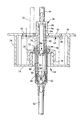
図1は、一般的な公衆トイレのカウンタ11に設置された本発明のディスペンサ装置10を示す。図示のように、ディスペンサ装置は、洗面ボウル16に隣接して配置されたカウンタ上側部分14を有するディスペンサ部12を含む。図示のように、カウンタ上側部分14は、供給口20を有するディスペンサヘッド18を含む。供給口20は、ディスペンサヘッド18から延出している。供給口20は、ソープ剤または他の粘性流体をユーザの手に供給するために、従来の方法で配置及び構成されている。意図せずに粘性液体がディスペンサ装置から供給された場合に、粘性液体がカウンタ11ではなく洗面ボウル16内に落下するように、図示のように、供給口20は洗面ボウル16の上方に配置されている。ディスペンサ装置から粘性流体を供給する際は、ユーザは作動ボタン22を押してポンプを作動させ、或る量の粘性液体をユーザの手に供給する。あるいは、ディスペンサ装置は、供給口の下方におけるユーザの手の存在を検出することができるように配置された電子センサ21を有することができる。電子センサ21が供給口の下方におけるユーザの手の存在を検出すると、電子的手段が作動し、或る量の粘性液体がユーザの手に供給される。
FIG. 1 shows a
ディスペンサ部12は、カウンタ下側部分24を含む。カウンタ下側部分24は、ディスペンサ部12をカウンタに固定するための取付けシステム25を有する。取付けシステム25は、細長いチューブ26を有する。細長いチューブ26は、一般に細長い中空チューブであり、カウンタ11に画定された孔を通って延びている。「中空」とは、細長いチューブ26が、細長いチューブ26の近位端26P(カウンタ11の上側に位置する)から細長いチューブ26の遠位端26D(カウンタ11の下側に位置する)まで延びる通路または流路(図1では図示しない)を有することを意味する。細長いチューブ26は、該チューブのカウンタ11の上側に位置する終端部にフランジ23が有する。フランジ23は、カウンタ11の孔よりも大きいサイズを有し、細長いチューブ26がカウンタ11から抜け落ちないように保持する役割を果たす。図1に示すように、取付けシステム25はまた、カウンタ11の下方に延びる細長いチューブ26の一部と係合した固定機構28を有する。図1に示した取付けシステムは、本発明で使用し得る取付けシステムの1つのタイプである。他のタイプの取付けシステムも使用し得ることに留意されたい。図1に示した取付けシステム25では、細長いチューブ26の外周面にねじ部が形成されており、固定機構28は細長いチューブ26のねじ部と螺合することができるナットである。図1に示した取付けシステム25の代わりに使用し得る他の取付けシステムには、本発明の別の実施形態で説明する取付けシステムが含まれる。本発明の別の実施形態の取付けシステムの詳細は後述する。
The
カウンタ下側部分24はまた、細長いチューブ26の遠位端26Dに設けられた連結部材30を有する。連結部材30は、その上側部分29が、細長いチューブ26の遠位端26Dに取り外し可能に結合されている。連結部材30は、ディスペンサ装置10から供給する粘性液体を収容している容器アセンブリ32を支持する。容器アセンブリ32は、容器アセンブリ32内の粘性液体が使い果たされたときに容器アセンブリを取り外して交換することができるように、連結部材30の下端部31(容器連結面とも呼ばれる)に取り外し可能に連結されている。
The
図2を参照して、容器アセンブリ32は、容器本体部36と容器上側部分38とを有する容器ハウジング34を含む。容器本体部36は、ディスペンサ装置から供給する粘性液体を収容し保持する役割を果たす。容器上側部分38は、容器本体部36に取り外し可能にまたは恒久的に固定されている。例えば、容器上側部分38は、超音波溶接、接着剤、または他の適切な手段を用いて、容器本体部36に封止され得る。容器上側部分38を容器本体部から取り外し可能に構成することが望ましい場合は、容器上側部分38及び容器本体部36に互いに螺合するねじ部をそれぞれ形成するなどの公知の方法を用いて、容器上側部分38を容器本体部36に結合させることができる。また、他の同様の方法を用いて、容器上側部分38を容器本体部36に取り外し可能に固定することもできる。
With reference to FIG. 2, the
図2に示すように、容器ハウジングの容器上側部分38はまた、取付け要素40を有する。取付け要素は、容器アセンブリ32をディスペンサ装置10の残りの部分に連結させる役割を果たす。本発明では、取付け要素40は、連結部材30により形成される面(容器連結面)に対して、あらゆる回転角度で係合させることができるように設計されている。すなわち、容器上側部分38に設けられた取付け要素40と連結部材30とが、連結部材30の前記面においてあらゆる回転角度で互いに係合することができる。したがって、容器アセンブリ32を連結部材30に連結させる際に、従来のように両者が互いに或る特定の周角度となるように位置合わせする必要はない。
As shown in FIG. 2, the container
本発明では、容器上側部分38の取付け要素40は、連結部材30に設けられた相補的な取付け要素と係合するように構成されている。容器32をディスペンサ装置10の残りの部分に連結させるために本発明で使用し得る取付け要素としては、ディテント(detent)要素を有する可動部材、またはディテント要素と係合するように構成された凹部を有する静止部材がある。ディテント要素を有する可動部材の例には、カラーがボールベアリングから離れたときに前後に移動し、カラーがボールベアリングの周囲に位置したときロックするように構成されたクイック連結具が含まれる。ディテント要素を有する別の可動部材を、図3及び図4Aに示す。図4Aは、ディテント要素を有する可動部材の拡大図である。
In the present invention, the mounting
図4Aに示すように、可動部材140は、ディテント要素141を有する。可動部材140は、支点142を中心として動作可能である。ディテント要素141は、可動部材140における支点142とは反対側の端部に位置する。可動部材140は、支点142とディテント要素141との間の位置にアーム143を有し得る。アーム143は、直立部分144を有し得る。直立部分144は、ユーザが可動部材140に対してディテント要素141の方向に力を加えることを可能にする。可動部材140をディテント要素241の方向に動かすことにより、ディテント要素141と連結部材との係合を解除し、容器32または容器上側部分38を連結部材30から取り外すことができる。
As shown in FIG. 4A, the
図4Aに示すように、使用中に容器アセンブリ32を所定位置に保持すべくディテント要素141と接触し係合する連結部材30は、ディテント要素141と係合するように構成された凹部131を有している。凹部131は、連結部材30の下端部31から突出したリップ部132により形成される。凹部131のサイズ及び形状は、ディテント要素141と容易に係合することができるが、ディテント要素141が凹部131内で遊離するほどは大きくないようなサイズ及び形状にするべきである。
As shown in FIG. 4A, the connecting
凹部を形成するリップ部132は、傾斜または湾曲した下面133を有し得る。加えて、ディテント要素141は、傾斜または湾曲した上面145を有し得る。図4Aに示すように、リップ部の下面及びディテント要素の上面が湾曲または傾斜した形状を有することにより、容器34の連結部材30への取り付けがより容易になる。これは、図4Bに示すように、容器ハウジング34を上側方向に移動させてディテント要素141を連結部材30のリップ部下面133に押し付けたときに、ディテント要素141をリップ下面133の外縁部134へ向けて緩やかに押し進めることができるからである。このことにより、ディテント要素141を凹部131と係合させることを可能にする方向150へ、可動部材140を動かすことができる。ディテント要素141の先端部148がリップ132の外縁部134の上側にくると、可動部材140に作用している力が解放され、可動部材は図4Aに示す係合位置に位置することとなり、これにより、容器アセンブリ32が連結部材に連結される。
The
容器32を連結部材から取り外すときは、図4Cに示すように、アームの直立部分144に対して力146を加える。このことにより可動部材140を動かすことができ、これにより、ディテント要素141を凹部131から脱離させることができる。ディテント要素141を凹部131から脱離させた後、図4Cに示すように、容器32を下側方向147に引っ張ることにより容器32を連結部材30から取り外すことができる。
When the
図5に示すように、連結部材30は、その下面(すなわち容器係合面)31及び凹部131が円形である限りはあらゆる形状をとり得る。円形の凹部131を有することにより、容器ハウジング34の容器上側部分38に設けられたディテント要素が有する可動部材140を、容器係合面31の下方向または面方向におけるあらゆる方向から、凹部131に係合させることが可能となる。このことにより、連結部材30の下面31の周囲のあらゆる方向から、ディテント要素141を凹部131に適切に係合させることが可能となる。本発明の一実施形態では、可動部材140及びディテント要素141は、図2及び図6に示すように、円狐を描くように形成されている。ディテント要素141の半径(曲率)は、連結部材30の凹部131の半径(曲率)と略一致する。このことにより、容器アセンブリ32の容器上側部分38と連結部材30の下面31との適切な連結を確実に行うことができる。
As shown in FIG. 5, the connecting
一般的に、容器アセンブリ32の容器上側部分38には、2個以上の可動部材140が設けられている。一般的に、最大で約20個の可動部材140を設けることができる。可動部材140及びそれに関連するディテント要素141は一般的に、2個の可動部材140が互いに容器上側部分38の直径方向の反対側に配置されるように、偶数個設けられる。偶数個の可動部材140を互いに容器上側部分38の反対側の側面に配置することにより、容器上側部分38の結合部材30への十分な連結を実現することができる。本発明の特定の一実施形態では、図6に示すように、可動部材140は2個1組にして、容器上側部分38の両側に配置される。容器上側部分38の両側に可動部材140を2個1組にして配置することにより、連結部材30への容器アセンブリ32の連結中に1個のディテント要素140が壊れた場合でも、容器アセンブリ32を連結部材30に連結した状態を維持することができる。加えて、可動部材140及びディテント要素141は一般的に、図1及び図2に示すように、容器上側部分38の周囲の2箇所にのみ設けられる。可動部材及びディテント要素は、容器上側部分38の周囲の2箇所よりも多い箇所に設けることもできることに留意されたい。しかし、その場合は、容器アセンブリを連結部材から取り外す際に全てのディテント要素141の係合を同時に解除する必要があるので、連結部材からの容器アセンブリの取り外しはより難しいものとなる。
Generally, the container
図1、図2、図3、図4A、図4B及び図4Cに示すように、ディテント要素141は、容器アセンブリ32の容器上側部分38の可動部材140に設けられる。しかし、容器アセンブリ32の容器上側部分38に凹部を設け、連結部材30の下面31に可動部材140及びディテント要素141を設けることも可能である。そのような構成は、図1ないし図5に示した実施形態と同様に作用する。しかし、連結部材30への容器アセンブリ32の連結及び取り外しを何度も繰り返すとディテント要素141は損耗するので、図1ないし図5に示した実施形態の方が好適である。ディテント要素141を容器アセンブリ32の容器上側部分38に設けた場合は、容器を交換するたびにディテント要素141も交換されるからである。
As shown in FIGS. 1, 2, 3, 4A, 4B, and 4C, the
図1、図2、図3、図4A、図4B及び図4Cに示すように、ディテント要素141は、容器アセンブリの中央軸1から見て外側を向くように配置される。しかし、ディテント要素141は、容器アセンブリの中央軸1の方を向くように配置することもできる。そのような場合は、と相補的な取付け部材に形成された凹部は、連結部材30の外側に露出することとなる(図示せず)。作動における唯一の差異は、可動部材の支点142の位置を、ディテント要素141とアーム143の取付け点との間に配する必要があることである。これは、ディテント要素を凹部131から脱離させる際に、可動部材140及び戻り止め141を互いに反対方向に動くように構成する必要があるからである。
As shown in FIGS. 1, 2, 3, 4A, 4B and 4C, the
図5に示すように、連結部材30は、その中央領域に、開口部137をさらに有する。開口部137は、連結部材30を細長い中空チューブ26の遠位端26Dに取り付けたときに、細長いチューブ26の遠位端26Dから近位端26Pまで延びる細長いチューブ26の中空部分または通路と連通する。したがって、細長いチューブ26の中空部分は、連結部材30の下側へ延びることとなる。また、ディスペンサヘッド18の供給口20も、細長いチューブ26の中空部分と連通する。
As shown in FIG. 5, the connecting
再び図2を参照して、容器ハウジング34は、容器上側部分38の流体出口46から延出する柔軟性の供給チューブ44を有する。この流体出口46は、容器ハウジング34内に収容されているポンプ装置(後述する)の出口に接続されている。容器ハウジング34が連結部材30に連結されているときは、供給チューブ44は、連結部材30の開口部137に挿入され、細長いチューブ26の中空部分を通って、ディスペンサヘッド18及び供給口26へ延びる。供給チューブ44の長さは、その先端部48が供給口20の端部をちょうど超えた位置に位置するように設定される。流れを向上させるために、図3に示すように、端部48は半球形であり得る。ディスペンサヘッド18及び供給口20内に延在する柔軟性の供給チューブを有することにより、粘性液体を供給する際に、粘性液体がディスペンサヘッド18及び供給口20の内面と接触することがなくなる。また、容器アセンブリ32を交換するたびに供給チューブ44が新しいものに取り替えられることとなるので、ディスペンサヘッド18の出口を定期的に清浄する必要をなくするまたは減らすことができる。
Referring again to FIG. 2, the
容器上側部分38はまた、容器上側部分38の中心線の周りに位置するアクチュエータ開口部50を画定する。本発明の一実施形態では、図2に示すように、流体出口46は、アクチュエータ開口部50の中央に位置する。図3に見ることができるように、アクチュエータ開口部50は、ポンプを作動させて1回分の粘性液体を供給するためにアクチュエータロッド52がポンプ作動要素64と係合することができるようにするための単一の開口部である。図3に明確に示すように、ディスペンサヘッド18が手動式のディスペンサヘッドである場合、ディスペンサ部はアクチュエータロッド52を有する。アクチュエータロッド52は、容器アセンブリ32を連結部材30に連結したときに、ディスペンサヘッド18から、細長いチューブ26の中空部分、連結部材30の開口部137、及びアクチュエータ開口部50を通って下方に延びる。
The container
作動ボタン22を押すことにより、ポンプを手動で作動させることができる。つまり、ユーザが作動ボタン22を押すとポンプが作動し、或る量の粘性液体を容器から供給口20へポンプで供給するように構成されている。あるいは、ユーザが作動ボタン22を押すと電気モータが作動し、電気モータによりポンプを作動させるように構成することもできる。本発明の別の実施形態では、センサ21を使用してユーザを検出し、ユーザが検出されたときに電気モータを駆動させてポンプを作動させるように構成することもできる。ポンプを電気的に作動させる方法の詳細については後述する。
By pressing the
一般的に、ディスペンサヘッド18が図3に示すような手動式のディスペンサヘッドである場合、作動ボタン22がアクチュエータロッド52に直接的または間接的に接続されている。図3に示すように、アクチュエータロッド52は、連結要素54を介して、ロッド部品56に連結されている。ロッド部品56は、作動ボタン22に結合されている。したがって、ユーザが作動ボタン22を押すと、アクチュエータロッド52は、垂直下側方向に動かされる。
Generally, when the
ポンプ装置58は、粘性液体60を吸込みチューブ62内に引き込むために、容器32内に設置されている。粘性液体は、ポンプ58を通って、供給チューブ44から押し出される。ポンプは、作動開口部50に位置合わせされた係合部分を有するポンプ作動要素64の上下往復運動により作動させられる。したがって、ユーザが作動ボタン22を押したとき、アクチュエータロッド52の自由遠位端がポンプ作動要素64の係合部分を押圧する。
The
ポンプ装置58は、製造効率を向上させるために、幅広く入手可能な「在庫」部品から構成することが好適である。具体的には、ポンプ装置58は、容器に詰められたローション(例えばシャンプーなど)と共に広範に使用されるタイプの一般的なローションポンプであることが好ましい。いくつかの用途においてこのために好適であり得るそのようなポンプの1つは、マルマー社(Calmar, Inc.)製のSD−200型である。様々な他のタイプのローションポンプも市販されており、例えばショットサイズなどの様々な変数に応じて使用可能である。後述するように、ポンプ装置は、容器アセンブリ32内で使用するために、種々の方法で改変され得る。
The
本発明において使用することができる例示的なポンプについてのより良い理解を得るために、図7を参照して説明する。図示のように、ポンプ装置58は、ポンプシリンダ68内に配置されたピストン66を含む。ポンプ58は、チャプレット72によって、ポンプシリンダ68に対して軸方向に固定された関係に維持されたキャップ要素70をさらに含む。キャップ要素70は、有利なことに、ポンプ装置58を容器アセンブリ32内に設置するのに使用される。
To gain a better understanding of an exemplary pump that can be used in the present invention, it will be described with reference to FIG. As shown, the
図7に見ることができるように、容器アセンブリ32は、容器ハウジング34に固定的に連結されたポンプ取付け要素74を含む。一般的に、ポンプ取付け要素74は、容器ハウジングの上側部分38の一部であり得る。図示した実施形態では、例えば、取付け要素74は、ねじ部76を有するディスク状部材として構成される。図示のように、ねじ部76の外側ねじが、キャップ要素70の内側ねじと螺合する。取付け要素74の周辺部は、溶接、接着または他の適切な手段により、ポンプ取付け要素74の壁部78に接合される。壁部78は、図示のように、容器上側部分38の下面まで延びる。容器ハウジング34へのポンプアセンブリ58の取り付けは、他の適切な手段を用いて行うこともできる。
As can be seen in FIG. 7, the
ポンプ作動要素64は、ポンプのピストン66に結合されている。図示した実施形態では、ポンプ作動要素64は、円筒状部分79と、係合部分80を形成するディスク状のフランジとを有するように構成されている。ポンプ作動要素64は、容器アセンブリの中心軸の近傍に配置されている。ポンプ作動要素64の上下方向の往復運動により、シリンダ内でピストン66を上下方向に移動させる。ピストン66は、ヘリカルばね82の付勢力により、通常は上側方向に付勢されている。
粘性液体が適切に流れるようにするために、ポンプ装置58には一対のチェックバルブ84及び86がさらに設けられる。ポンプシリンダ68の基底部に配置されたチェックバルブ84は、ピストン64を上側方向に移動させたときに、粘性液体が下側ポンプチャンバ88内に吸い込まれることを可能にする。一方、チェックバルブ86は、ピストン64を下側方向に移動させたときに、粘性液体が上側ポンプチャンバ90内に注入されることを可能にする。その結果、粘性液体が柔軟性チューブ44に注入され、柔軟性チューブ44を通じて供給されることとなる。様々な構造のチェックバルブが考えられるが、図示した実施形態では、一般的なボール・シート型バルブを用いている。典型的な形態では、図示のように、適切なケージ92が下側チャンバ88内に設けられる。
In order to allow the viscous liquid to flow properly, the
図示のように、エゼクタ(排出装置)94は、液体出口46のチューブ受容部分96の内部で往復運動する。ここでは適切なOリングシールの形態のシール要素98が、エゼクタ94の外面とチューブ受容部分96の内面との間に延在して設けられている。したがって、粘性液体は、柔軟性チューブ44内にのみより完全に導入される。
As shown, the
一般的に、ポンプ装置58は、容器アセンブリ32の容器ハウジング34の容器上側部分38内に収容される。あるいは、ポンプ装置58は、容器本体部36内に収容される。しかし、製造の容易さという観点から、ポンプ装置は通常は容器アセンブリ32の容器上側部分38内に配置される。
Generally, the
図3に示すように、ポンプは手動で作動される。つまり、ユーザが作動ボタン22を押すと、ポンプが作動し、容器から供給口20に或る量の粘性液体が供給される。本発明の別の実施形態では、ポンプは電動で作動される。粘性液体の電動式ディスペンスシステムの一例が図8に示されている。電動で作動されるポンプは、様々な方法で作動させることができる。1つの方法は、ディスペンサヘッドまたはその近傍に設置された作動ボタン22をユーザが押すことか、あるいは、供給口20の下方におけるユーザの手の存在を検出するセンサ23を設置することである。
As shown in FIG. 3, the pump is operated manually. That is, when the user presses the
図8に見ることができるように、粘性液体の電動式ディスペンスシステムは、ディスペンサヘッド18と、細長いチューブ26と、モータハウジング102と、電源ハウジング104と、連結部材30と、容器アセンブリ32とを含む。基本的に、この構成は、モータハウジング102が細長いチューブ26と連結部材30との間に配置されたことを除いては、前述したディスペンスシステムの構成と同様または同一である。加えて、電源ハウジング104は、モータと電気的に接続される電源を収容する。ディスペンサヘッド18は、ポンプに連結されたモータを作動させるのに使用される作動ボタン22及び/またはセンサ23を有する。作動ボタン22及び/またはセンサ23は、モータと電気的に接続される。一般的に、作動ボタン22及び/またはセンサは、供給口20の下方におけるユーザの手の存在、またはユーザが作動ボタン22を押したことを検出するのに使用される制御回路を有する制御パネル(図示せず)と電気的に接続される。加えて、制御回路は、ユーザが1回分の粘性液体を受け取るように、モータを所定期間作動させるのに使用される。センサ及び作動ボタン用の制御回路は当業者には公知であり、例えば、この引用により本明細書に組み込まれる、Muderlakらに付与された米国特許第6,929,150号明細書(特許文献2)に記載されている。
As can be seen in FIG. 8, the viscous liquid motorized dispensing system includes a
この粘性液体電動式ディスペンスシステムでは、連結部材30は、モータハウジング102及び電源ハウジング104に連結される。あるいは、モータハウジング102は、連結部材30と一体化される。つまり、モータハウジング102及び連結部材30は単一の部材として構成される。一般的に、電源ハウジング104は、交換が必要となったときに交換することができるように、モータハウジングから分離させることができる。すなわち、電源ハウジングは、モータハウジングとの連結を解除することが可能であり、かつモータハウジングと再び連結させることが可能である。電源ハウジング104からモータハウジングに電力を伝達させることができるように、モータハウジング及び電源の両方に電気接触子が設けられ得る。電源がモータハウジングに取り付けられたときに電気的接続がなされるように、電気接触子は互いに相補的な関係となるように設置される。
In this viscous liquid electric dispensing system, the connecting
モータハウジング102の可能性のある構成についてのより良い理解を得るために、図9A、図9B、図9C及び図9Dを参照して説明する。モータハウジング102は、モータ110、ギア111、112を収容する。ギア111、112は、モータ110、及びアクチュエータロッド52Eを駆動する追加的なギア113と噛合する。モータにより駆動されるアクチュエータロッド52Eは、モータハウジング102内に収容されており、連結部材30の下面31に設けられた開口部からモータハウジング102の外部へ延出する。モータ駆動式のアクチュエータロッド52Eは、任意の方法を用いて駆動させることができる。粘性液体の電動式ディスペンスシステムの典型的な作動は図3に示したのと同様のやり方で行われ、モータ駆動式のアクチュエータロッド52をポンプ作動要素64と係合させてポンプ作動要素58を下側に押し、ポンプ58を1回または複数回作動させることにより、ディスペンサヘッド18の供給口20から1回分の粘性液体を排出する。
To gain a better understanding of the possible configuration of the
作動させたモータからモータ駆動式アクチュエータロッド52Eへの動力の伝達は、様々な方法が用いて行われ得る。例えば、モータは、一連のホイール、ギア、または、ポンプ作動要素64まで延在しポンプ作動要素と係合するアクチュエータロッド52Eへの他のエネルギー伝達手段を駆動させる。アクチュエータロッド52Eを駆動させるのに使用される例示的な手段を意図する本発明の一実施形態では、図9A及び図9Bに示すように、駆動ホイール113は、ギア本体の周辺部115の近傍の或る領域から延出するポストすなわちシャフト114を有する。モータ110がモータ駆動式ホイール111を回転させると、モータ駆動式ホイール111は、1若しくは複数のホイール112を回転させる。図9Aでは、単一のホイール112が図示されているが、ポンプが制御された方法で駆動されるように、アクチュエータ駆動ホイール113の回転速度を減少させるために複数のホイールを設けることが望ましい。当業者であれば、アクチュエータ駆動ホイール113が適切な速度で回転するように駆動ホイールの回転比を選択することが可能であろう。本明細書においては「ホイール」なる用語は、それ自体が複数のホイールを有するものや、ギアなどの他のホイール様機構などを含む、あらゆるホイール様機構を包含することを意図することに留意されたい。ギアは使用中に滑りにくいので、ギアを用いることが一般的には望ましい。
Transmission of power from the activated motor to the motor-driven
図9Bに示すように、アクチュエータ駆動ホイール113は、その非中心領域から延びるシャフト114を有する。ホイール113が回転すると、シャフト114は矢印125の方向に上下移動する。シャフト114は、アクチュエータガイド部材122に設けられた水平チャンネル120に嵌合している。水平チャンネル120は、一般的に水平軸2方向に形成されている。水平チャンネル120は、アクチュエータガイド部材120の側面の一方から延出する2つの水平突起121及び121´によって形成される。アクチュエータ駆動ホイール113が回転すると、シャフト114が円軌道を描いて移動し、垂直軸1方向の垂直移動125(図9B参照)及び水平軸2方向の水平移動126(図9C参照)を行う。シャフト114の垂直移動125は、アクチュエータガイド部材122を垂直軸1方向に上下移動させ、それにより、モータ駆動式アクチュエータロッド52Eを垂直軸1方向に上下運動させる。アクチュエータガイド部材122に設けられた水平チャンネル120の下側には、アクチュエータロッドが配置されている。アクチュエータガイド部材122は、垂直軸方向に上下移動するが、左右方向または前後方向には移動しないように、所定の位置に保持される。アクチュエータガイド部材122は、例えばアクチュエータガイド部材122の左右両側部が水平軸方向の所定位置に保持されるように垂直ガイドスロット123を設けることにより、所定の位置に保持される。このような垂直ガイドスロット123は、図9B、図9C及び図9Dに示すように、モータハウジング102内に設けることができる。
As shown in FIG. 9B, the
上述したように、シャフト114はまた、水平軸2方向の水平移動126も行う。この水平移動は、基本的には不要である。シャフトがアクチュエータガイド部材内の水平チャンネル120に沿って水平軸2方向に水平移動することにより、この水平移動を相殺することができる。このようにして、水平チャンネル120により、シャフト114の基本的には不要な水平移動126を制御することができる。
As described above, the
粘性液体の電動式ディスペンスシステムはまた、さらなる特徴を有し得る。例えば、ディスペンサヘッド18に、ユーザを認識したこと、電池の残量が低下したこと、容器内のソープが空になったこと、またはモータの故障などの他の状態の表示などの様々な事象を知らせるための表示灯を設けることができる。そのような表示灯の例には、例えばLED(発光ダイオード)などの消費電力が低いものが含まれる。
The viscous liquid motorized dispensing system may also have additional features. For example, the
本発明の粘性液体電動式ディスペンスシステムの電源には、使い捨て型のDC電池(図示せず)が含まれ得る。あるいは、前記電源は、電源全体が単一ユニットして交換する必要がある閉鎖系システムであり得る。また図示しないが、ACからDCへ変換するアダプタも、粘性液体ディスペンサに対して別の電源を提供するために使用され得る。この実施形態は、粘性液体ディスペンサがACコンセントのすぐ近くに設置される場合や、中央に配置された適切な構造及び電力の変圧器から複数のディスペンサに電力供給することが所望される場合に、特に有用である。モータに電力を供給するのに使用される電池の数は、ディスペンサのために選択されたモータの種類に依存する。本発明に用い得る使い捨て型の電池には、9ボルトの電池、1.5ボルトの電池(例えば単1電池や単2電池)、または他の同様の電池が含まれる。モータに供給される電力がモータに適合さえすれば、使用するために選択される電池の正確な種類は、本発明にとって重要ではない。粘性液体ディスペンサの使用頻度が低い場合は、充電可能な電池を使用することができる。ディスペンサが明るい場所で使用される場合は、電池は、ソーラー充電式の電池を使用することができる。 The power source of the viscous liquid electric dispensing system of the present invention may include a disposable DC battery (not shown). Alternatively, the power source may be a closed system where the entire power source needs to be replaced as a single unit. Also, although not shown, an adapter that converts from AC to DC can also be used to provide another power source for the viscous liquid dispenser. This embodiment may be used when a viscous liquid dispenser is installed in the immediate vicinity of an AC outlet or when it is desired to power multiple dispensers from a centrally located appropriate structure and power transformer. It is particularly useful. The number of batteries used to power the motor depends on the type of motor selected for the dispenser. Disposable batteries that can be used in the present invention include 9 volt batteries, 1.5 volt batteries (eg, single batteries or single batteries), or other similar batteries. As long as the power supplied to the motor is compatible with the motor, the exact type of battery selected for use is not critical to the present invention. When the use frequency of the viscous liquid dispenser is low, a rechargeable battery can be used. If the dispenser is used in a bright place, the battery can be a solar rechargeable battery.
本発明の別の実施形態では、粘性液体ディスペンサをカウンタに取り付けるための取付けシステムが提供される。本発明のこの実施形態についての理解を得るために、図10及び図11を参照して説明する。取付けシステム200は、近位端204と、遠位端206と、近位端204から遠位端206まで延在する中空シャフト208とを有する細長い構造体226を含む。近位端204またはその近傍に、フランジ201が設けられている。フランジ201は、細長いチューブ226が、カウンタ11の孔(図示せず)から抜け落ちないようにする役割を果たす。固定機構212が、フランジ201と遠位端206との間に、細長いチューブ226の側面に沿って配置されている。固定機構212はまた、中空シャフト208の側面に沿って配置されている。固定機構212は、近位端204またはその近傍に配置された固定機構係合部材214と連結される。固定機構係合部材214は、固定機構212と係合可能に連結される。固定機構係合部材214の第1の端部216は、固定機構212を固定位置に移動させるために、固定機構係合部材214を回転させる手段を有する。固定機構係合部材214を回転させる手段の例には、例えばマイナスドライバ、プラスドライバ、トルクスドライバ、六角ドライバなどの、一般的なねじ回しと係合するようにデザインされた頭部が含まれる。
In another embodiment of the invention, an attachment system for attaching a viscous liquid dispenser to a counter is provided. To gain an understanding of this embodiment of the invention, reference is made to FIGS.
取付けシステム200は、カウンタに取り付けたときに、固定機構212がカウンタ11の下面と直接的または間接的に係合し、フランジ201がカウンタ11の上面上に直接的または間接的に載置されるように構成されている。固定機構係合部材214の第2の端部217は、細長い構造体226の遠位端またはその近傍の所定位置に保持される。固定機構係合部材214は、固定機構212をカウンタ11の下面と係合する位置まで移動させることにより、固定機構212を固定位置に配置させるように構成されている。固定機構係合部材214を回転させることにより、固定機構212は上側方向235へ移動させられる。
When the mounting
この取付けシステムは、カウンタ11とフランジ201との間に配置されるガスケット202を随意的に有し得る。ガスケット202は、水やほこりがカウンタ11とフランジ201との間に侵入し、カウンタ11に形成された細長いチューブ226の挿入孔を通過して落下しないように、カウンタ11とフランジ201との間にシールを形成する役割を果たす。ガスケット202はまた、フランジ201によってもたらされ得る損傷からカウンタ11を保護する役割を果たす。カウンタ11の下側には、細長いチューブ226を取り囲むようにして、随意的なスペーサ218が設置される。固定機構212と係合するための清潔な係合面を提供するために、スペーサ218はカウンタの下面と係合接触するようにデザインされている。このスペーサは随意的なものであり、カウンタ11に孔を形成したときにカウンタ11の下面が損傷した場合にのみ必要とされる。いずれにせよ、スペーサ218は、取付けシステム200のカウンタ11への良好な取り付けを提供することができる。
This mounting system may optionally have a
本発明の一実施形態では、固定機構係合部材214は、細長い構造体226の近位端204の近傍から、細長い構造体226の側面及び中空シャフト208の側面に沿って下側へ延びるねじ部材であり得る。固定機構212は、上側部分230及び下側部分232を有する移動可能なウイング状部材であり得る。上側部分230は、細長い構造体226から外側へ延出しており、下側部分232は細長い構造体226に隣接して配置されている。固定機構212をガイドするために、固定機構212は、フランジ201の下側及び遠位端206の上側において細長い構造体226の側面に設けられたチャンネル234内に配置され得る。図10及び図11に示すように、細長い構造体226の両側面に沿って、2つのチャンネル234が設けられている。チャンネル234は、固定機構の下側部分232をチャンネル内に位置させることにより、固定機構212をガイドする役割を果たす。固定機構212は、ねじ部材215と直接的に螺合させられるか、あるいは、ねじ部材15と間接的に螺合させられる。「直接的に螺合させられる」とは、固定機構212の一部をねじ部材215と螺合させることを意味する。「ねじ部材と間接的に螺合させられる」とは、ねじ部材215を回転させたときに固定機構212が上下方向に移動するようにして、ナットなどの部材をねじ部材215と螺合させることを意味する。ナットは、ナットを回転させなければ固定機構212がねじ部材215上で上下方向に移動しないようにして、固定機構212をねじ部材215上の所定位置に保持する役割を果たす。
In one embodiment of the present invention, the locking
図10及び図11に示す取付けシステムをカウンタに取り付けるために、フランジ201を有する細長い構造体226がカウンタ11の孔に挿入される。一般的に、固定機構212は、細長い構造体226の遠位端206の近傍においてチャンネル234内に配置される。随意的に、細長い構造体226をカウンタ11の前記孔に挿入する前に、ガスケット202が、カウンタ11の上面における前記孔の周囲に配置されるか、あるいは細長い部材に装着される。必要または所望に応じて、随意的なスペーサ218が、細長い構造体226を取り囲むように設けられる。次に、固定機構係合部材214の上端216を回転させて、固定機構212を上側方向235へ移動させる(図11参照)。固定機構係合部材をそれ以上回転させることができなくなるまで回転させ、固定機構212をカウンタ11の下面までか、あるいはスペーサ218(設けられた場合は)まで移動させる(図11A参照)。フランジ201と固定機構212とでカウンタ11を挟むことにより、取付けシステムをカウンタの所定位置に保持する。
To attach the mounting system shown in FIGS. 10 and 11 to the counter, an
本発明に用い得る取付けシステムの別の実施形態を図12に示す。本発明のこの実施形態では、取付けシステム200は、近位端204と、遠位端206と、近位端204から遠位端206まで延在する中空シャフト208とを有する細長い構造体226を含む。近位端204またはその近傍に、フランジ201が設けられている。フランジ201は、細長いチューブ226が、カウンタ(図12では図示せず)に形成された孔(図示せず)から抜け落ちないようにする役割を果たす。中空シャフト208の遠位端206またはその近傍にはカラー240が設けられている。カラー240は、ねじ部245を有する中空のねじ部材244を受容しかつねじ部材244と係合するように構成された内面242を有する。内面242を中空のねじ部材244を受容しかつねじ部材244と係合するように構成する方法の1つは、内面242に相補的なねじ部243を形成することである。細長い構造体226はまた、カラー240とフランジ201との間に配置された折り畳み可能なスリーブ部分246を有する。この折り畳み可能なスリーブ部分246は、様々な公知の方法により作成することができ、例えば、細長いチューブ226の或る領域を他の領域よりも弱く形成することにより、または、細長いチューブ226の側面に沿って1若しくは複数の線を形成することにより、または、細長いチューブ226の側面に沿ってスリットを形成することにより作成することができる。中空のねじ部材244は、ねじ部材244の頂部247の近傍に位置する開口249からねじ部材244の底部251まで延びる通路250を有する。
Another embodiment of a mounting system that can be used with the present invention is shown in FIG. In this embodiment of the invention,
取付けシステム200をカウンタに固定するために、図12に示すように、中空のねじ部材244を細長い構造体226の近位端204に挿入する。中空のねじ部材244のねじ部245が、カラー240の内面242に形成されたねじ部243と螺合する。ねじ部材244の頂面247は、図12Aに示すようなねじ回しなどのトルクデバイスと係合するように形成された溝部を有する。例えば、例えばプラスドライバやマイナスドライバなどのねじ回りと係合する溝248が形成されている。あるいは、開口部249を、六角ドライバまたは他の同様のドライバと係合するように形成することもできる。中空ねじ部材244のねじ部245を、カラー240の内面242のネジ部243と係合させた後、中空ねじ部材244を回転させる。
To secure the mounting
中空ねじ部材244を所定の方向に回転させると、カラー240がフランジ201に向かって移動する。このことにより、図12Bに示すように、カラー240がカウンタの下面ともう少しで係合する位置にくるまで折り畳み可能部分246が折り畳まれ、それにより、取付けシステムがカウンタ11に固定される。本明細書において説明した取付けシステムはいずれも、カウンタ11の上方から作業者が1人で設置することができる。
When the
上述した取付けシステムは、ディスペンサヘッドを細長いチューブ226の一部として有していないので、取付けシステムのフランジ201または細長いチューブ226の近位端206は、使用時にディスペンサヘッド(図示せず)を取付けシステム上の所定位置に保持し固定するように設計された係合部材260、262をさらに有する。本発明の一実施形態では、ディスペンサヘッドは、フランジ201上に設けられた係合部材と係合するように構成された相補的な係合部材を有する。係合部材の例には、フランジ部材201上に設けられた、ディテント要素260及び突起部262を有する係合部材が含まれる。フランジ部材201はまた、係合部材を取り付ける方向を設置作業者に示す表示部を含む。
Since the mounting system described above does not have a dispenser head as part of the
各取付けシステムの細長いチューブ226の各実施形態の遠位端206は、細長いチューブ226の遠位端をディスペンスシステムの他の部材(例えば、モータハウジング、連結部材、または他の部分)に連結することを可能にする連結手段を有する。例えば、細長いチューブ226の遠位端206は、ディスペンスシステムの他の部分と好ましくは取り外し可能に互いに連結することを可能にする、溝、凹部、戻り止め、または他の同様の機構を有し得る。
The
例えば図1に示すようなディスペンサヘッド18は、フランジから取り外し可能に作成することもできる。図13は、ディスペンサヘッド18の底面図である。図示のように、ディスペンサヘッド18は、底部プレート310と供給口20との間に配置された電子センサ21を有し得る。このセンサ21は、供給口20の下方におけるユーザの手の存在を検出するように設計されている。ユーザの手の存在が検出されたとき、センサはモータに信号を送信してポンプを作動させ、1回分の粘性液体をユーザの手に供給する。センサのための電力及びポンプへの信号は、その端部にコネクタ306を有する電線305を通じて伝達される。電線305は、細長いチューブ226の中空シャフト208を通じて下方に延び、モータハウジング内に設けられた電気コネクタに接続される。電線305は、モータハウジングまで届くのに十分な長さを有している。
For example, the
また、図13に示すように、底部プレートは、細長いチューブ226の中空シャフト208の位置に位置合わせされる開口部312を有する。開口部312は、通路315を介して供給口20に接続される。このことにより、図3に示したのと同じようにして、柔軟性の供給チューブ44を細長いチューブ26内に配置し、供給口20の先端部に到達させることが可能となる。
Also, as shown in FIG. 13, the bottom plate has an
底部プレート310は、フランジ201上に存在する係合機構260及び262に対して相補的な取付け手段を有する。相補的な係合機構の例には、例えば、ディスペンサヘッド18の底部プレート310に設けられた切欠部320が含まれる。切欠部320は、フランジ210に設けられた係合機構260と互いに係合するように構成されており、係合機構260と互いに係合することによりディスペンサヘッド18をフランジ210に固定する。加えて、底部プレートは、フランジ201の突起部に対して相補的な凹部322を有し得る。この特定の種類の係合部材または相補的な係合部材は、ディスペンサヘッド18を取り替える必要がある場合にディスペンサヘッドを取り外すことができるようにして係合機構がディスペンサヘッド18を細長いチューブ226に固定的に保持すること以外は、本発明にとって重要でない。
The
別の実施形態では、ディスペンサヘッドが図3に示したような手動式のディスペンサヘッドである場合は、ディスペンサヘッド18は、開口部312から延びるアクチュエータロッドを有し得る。
In another embodiment, if the dispenser head is a manual dispenser head as shown in FIG. 3, the
本発明では、本発明の取付けシステムを、本発明のディスペンサ装置と組み合わせて使用することができる。 In the present invention, the mounting system of the present invention can be used in combination with the dispenser apparatus of the present invention.
以上、本発明の様々な実施形態について説明したが、本発明の精神及び範囲から逸脱することなく形状及び細部を変更してもよいことは、当業者であれば理解できるであろう。したがって、前述の詳細な説明は限定ではなく例示を意図しており、添付の特許請求の範囲及びその全ての均等物は、本発明の範囲を規定することを意図している。 While various embodiments of the invention have been described above, those skilled in the art will appreciate that changes may be made in form and detail without departing from the spirit and scope of the invention. Accordingly, the foregoing detailed description is intended to be illustrative rather than limiting, and the appended claims and all equivalents are intended to define the scope of the invention.
Claims (17)
近位端、遠位端、前記近位端から前記遠位端まで延びる中空シャフト、前記近位端またはその近傍に設けられ前記カウンタの上面に直接的または間接的に載置されるように構成されたフランジ、及び前記フランジと前記遠位端との間に前記シャフトに沿って設けられ、前記カウンタの下面と直接的または間接的に係合するように構成された固定機構を有する細長い構造体と、
前記近位端またはその近傍に設けられ、前記細長い構造体を前記カウンタに固定すべく、前記固定機構を固定位置に配置させるように構成された固定機構係合部材と、
前記フランジと前記近位端との間に配置され、前記粘性液体ディスペンサのディスペンサヘッドを前記取付けシステムに固定する役割を果たすディスペンサヘッド固定部材とを含むことを特徴とする取付けシステム。 An attachment system for attaching a counter-mounted viscous liquid dispenser to a counter ,
Proximal end, distal end, hollow shaft extending from the proximal end to the distal end, provided at or near the proximal end and configured to be mounted directly or indirectly on the upper surface of the counter And an elongated structure having a locking mechanism disposed along the shaft between the flange and the distal end and configured to directly or indirectly engage the lower surface of the counter When,
A securing mechanism engaging member provided at or near the proximal end and configured to place the securing mechanism in a secured position to secure the elongated structure to the counter ;
The flange and the disposed between the proximal end, the mounting system comprising a serving dispenser head fixing member for fixing the dispenser head of the viscous fluid dispenser to the mounting system.
前記ディスペンサヘッド固定部材が、前記フランジ上に設けられ、前記ディスペンサヘッドに設けられた相補的な要素を係合する係合部材を含み、The dispenser head fixing member includes an engagement member provided on the flange and engaging a complementary element provided on the dispenser head;
前記係合要素は、ディテント要素及び突起部を含むことを特徴とする取付けシステム。The attachment system, wherein the engagement element includes a detent element and a protrusion.
前記遠位端から前記シャフトを取り囲むようにして前記シャフトに取り付けられ、前記カウンタの前記下面及び前記固定機構と係合接触するスペーサをさらに含むことを特徴とする取付けシステム。 The mounting system according to claim 1 or 2 ,
An attachment system further comprising a spacer attached to the shaft so as to surround the shaft from the distal end and in engagement with the lower surface of the counter and the fixing mechanism.
近位端、遠位端、前記近位端から前記遠位端まで延びる中空シャフト、前記近位端またはその近傍に設けられ前記カウンタの上面に直接的または間接的に載置されるように構成されたフランジ、及び前記フランジと前記遠位端との間に前記シャフトに沿って設けられ、前記カウンタの下面と直接的または間接的に係合するように構成された固定機構を有する細長い構造体と、
前記近位端またはその近傍に設けられ、前記細長い構造体を前記カウンタに固定すべく、前記固定機構を固定位置に配置させるように構成された固定機構係合部材と、
前記遠位端から前記シャフトを取り囲むようにして前記シャフトに取り付けられ、前記カウンタの前記下面及び前記固定機構と係合接触するスペーサとを含むことを特徴とする取付けシステム。 An attachment system for attaching a counter-mounted viscous liquid dispenser to a counter,
Proximal end, distal end, hollow shaft extending from the proximal end to the distal end, provided at or near the proximal end and configured to be mounted directly or indirectly on the upper surface of the counter And an elongated structure having a locking mechanism disposed along the shaft between the flange and the distal end and configured to directly or indirectly engage the lower surface of the counter When,
A securing mechanism engaging member provided at or near the proximal end and configured to place the securing mechanism in a secured position to secure the elongated structure to the counter;
An attachment system comprising a spacer attached to the shaft so as to surround the shaft from the distal end and in engagement with the lower surface of the counter and the fixing mechanism .
前記固定機構係合部材が、前記細長い構造体の前記近位端の近傍から、前記シャフトの側面に沿って下側へ延びるねじ部材を含み、
前記固定機構が、前記シャフトから外側へ延出する上側部分と前記シャフトに隣接して設置された下側部分とを有し前記ねじ部材と螺合するように構成された可動ウイングを含むことを特徴とする取付けシステム。 The mounting system according to any one of claims 1 to 4 ,
The locking mechanism engaging member includes a screw member extending downwardly along the side of the shaft from near the proximal end of the elongated structure;
The fixing mechanism includes a movable wing having an upper portion extending outward from the shaft and a lower portion disposed adjacent to the shaft and configured to be screwed with the screw member. Installation system featuring.
前記シャフトが、その外面に少なくとも1つのチャンネルを有し、
前記ウイングの前記下側部分が前記チャンネル内に位置し、かつ前記ウイングの前記上側部分が前記チャンネルから外側へ延出するようにして、前記ウイング及び前記ネジ部材が前記チャンネル内に配置されるように構成したことを特徴とする取付けシステム。 The mounting system according to claim 5 ,
The shaft has at least one channel on its outer surface;
The wing and the screw member are disposed in the channel such that the lower portion of the wing is located in the channel and the upper portion of the wing extends outward from the channel. An installation system characterized by comprising
前記シャフトが2つのチャンネルを有し、各チャンネル内に前記ウイング及び前記ねじ部が配置されるように構成したことを特徴とする取付けシステム。 The mounting system according to claim 6 ,
The mounting system, wherein the shaft has two channels, and the wing and the screw portion are arranged in each channel.
前記中空シャフトが、前記遠位端またはその近傍に設けられ、ねじ部材と係合可能に形成された内面を有するカラーと、前記カラーと前記フランジとの間に設けられた折り畳み可能なスリーブ部分とを含み、
前記固定機構係合部材が、前記シャフトの前記近位端から前記カラーまで延在し、前記カラーの前記内面と螺合するねじ部材を含み、
前記固定機構係合部材を所定の方向に回転させたときに、前記カラーが前記フランジに向かって移動し、それにより前記折り畳み可能スリーブが外側に広がるようにして折り畳まれて前記カウンタの前記下面と係合するように構成したことを特徴とする取付けシステム。 The mounting system according to any one of claims 1 to 4 ,
A collar having an inner surface provided at or near the distal end thereof and formed to be engageable with a screw member; and a foldable sleeve portion provided between the collar and the flange; Including
The locking mechanism engaging member includes a screw member extending from the proximal end of the shaft to the collar and threadably engaged with the inner surface of the collar;
When the fixing mechanism engaging member is rotated in a predetermined direction, the collar moves toward the flange, whereby the foldable sleeve is folded so as to spread outward, and the lower surface of the counter is An attachment system configured to engage.
前記遠位端が、前記細長い構造体を前記ディスペンサシステムのカウンタ下側部分に連結させるための連結手段をさらに含むことを特徴とする取付けシステム。 The mounting system according to any one of claims 1 to 4 ,
An attachment system , wherein the distal end further comprises connection means for connecting the elongated structure to a lower counter portion of the dispenser system .
前記カウンタと前記フランジとの間に配置されるように構成されたガスケットをさらに含むことを特徴とする取付けシステム。 The mounting system according to any one of claims 1 to 4 ,
The mounting system further comprising a gasket configured to be disposed between the counter and the flange.
請求項1乃至10のいずれかに記載の前記取付けシステムと、
前記取付けシステムに固定されるディスペンサヘッドと、
粘性液体を収容する容器アセンブリと、
前記取付けシステムの細長い構造体と前記容器アセンブリとに取り付けられる連結部材とを含み、
前記容器アセンブリが、
(i)中心軸を有し、かつ少なくとも1つのディテント要素をその表面に有する可動部材またはディテント要素と係合するべき凹部を有する静止部材からなる取付け要素を備える上側部分を有する容器ハウジングと、
(ii)前記容器ハウジング内に設置され、前記容器ハウジングの前記上側部分に画定された液体出口から前記粘性液体をくみ上げる働きを有するポンプ装置と、
(iii)前記ポンプ装置を作動させるベく、前記上側部分の前記中心軸に沿って配置されたポンプ作動要素とを含み、
前記連結部材が
前記上側部分の前記取付け要素に対して相補的であり、前記上側部分の前記取付け要素が少なくとも1つのディテント要素を有する可動部材である場合は少なくとも1つの凹部を含む静止部材であり、前記上側部分の前記取付け要素が少なくとも1つの凹部を有する静止部材である場合は少なくとも1つのディテント要素を含む可動部材である相補的取付け要素を有することを特徴とする粘性液体ディスペンサ装置。 A counter-mounted viscous liquid dispenser device,
The mounting system according to any of claims 1 to 10 ,
A dispenser head fixed to the mounting system;
A container assembly containing a viscous liquid;
An elongate structure of the attachment system and a coupling member attached to the container assembly ;
The container assembly comprises:
(I) a container housing having an upper portion with a central axis and having an attachment element consisting of a movable member having at least one detent element on its surface or a stationary member having a recess to be engaged with the detent element ;
(Ii) a pump device installed in the container housing and having a function of pumping the viscous liquid from a liquid outlet defined in the upper portion of the container housing;
(Iii) a pump actuating element disposed along the central axis of the upper portion to actuate the pump device;
A stationary member comprising at least one recess when the connecting member is complementary to the mounting element of the upper portion and the mounting element of the upper portion is a movable member having at least one detent element ; the attachment element viscous liquid dispenser apparatus, characterized in that it have a complementary attachment element is a movable member including at least one detent element when a stationary member having at least one recess of the upper portion.
前記取付け要素が、ディテント要素を有する可動部材からなることを特徴とする粘性液体ディスペンサ装置。 A viscous liquid dispenser device according to claim 11 ,
The viscous liquid dispenser device characterized in that the attachment element comprises a movable member having a detent element.
前記可動部材が、該可動部材における前記ディテント要素とは反対側の端部に設けられた支点を中心として動作可能であることを特徴とする粘性液体ディスペンサ装置。 A viscous liquid dispenser device according to claim 12 ,
The viscous liquid dispenser device , wherein the movable member is operable around a fulcrum provided at an end of the movable member opposite to the detent element.
少なくとも2つの前記可動部材を、前記容器ハウジングの直径方向において互いに反対側に配置されるようにして前記容器ハウジングに設置したことを特徴とする粘性液体ディスペンサ装置。 A viscous liquid dispenser device according to claim 13 ,
The viscous liquid dispenser device characterized in that at least two movable members are disposed on the container housing so as to be disposed on opposite sides in the diameter direction of the container housing.
4つの前記可動部材を2個1組にして、前記容器ハウジングの直径方向において各組が互いに反対側に配置されるようにして前記容器ハウジングに設置したことを特徴とする粘性液体ディスペンサ装置。 A viscous liquid dispenser device according to claim 14 ,
The viscous liquid dispenser device according to claim 1, wherein two sets of the four movable members are set as one set, and the sets are arranged on the container housing such that the sets are arranged on opposite sides in the diameter direction of the container housing.
前記可動部材が、前記支点と前記ディテント要素との間に、前記可動部材と平行に配置された直立部分を有するアーム部材をさら備えることを特徴とする粘性液体ディスペンサ装置。 A viscous liquid dispenser device according to claim 13 ,
The viscous liquid dispenser device , wherein the movable member further includes an arm member having an upright portion disposed in parallel with the movable member between the fulcrum and the detent element.
前記ポンプ装置が、前記容器ハウジングの前記上側部分内に配置されたことを特徴とする粘性液体ディスペンサ装置。 A viscous liquid dispenser device according to claim 11 ,
The viscous liquid dispenser device , wherein the pump device is disposed in the upper portion of the container housing.
Applications Claiming Priority (3)
| Application Number | Priority Date | Filing Date | Title |
|---|---|---|---|
| US12/006,130 US8100299B2 (en) | 2007-12-31 | 2007-12-31 | Counter-mounted viscous liquid dispenser and mounting system |
| US12/006,130 | 2007-12-31 | ||
| PCT/IB2008/055267 WO2009087510A2 (en) | 2007-12-31 | 2008-12-12 | Counter-mounted viscous liquid dispenser and mounting system |
Publications (3)
| Publication Number | Publication Date |
|---|---|
| JP2011514173A JP2011514173A (en) | 2011-05-06 |
| JP2011514173A5 JP2011514173A5 (en) | 2012-02-02 |
| JP5490018B2 true JP5490018B2 (en) | 2014-05-14 |
Family
ID=40796874
Family Applications (1)
| Application Number | Title | Priority Date | Filing Date |
|---|---|---|---|
| JP2010540195A Active JP5490018B2 (en) | 2007-12-31 | 2008-12-12 | Counter-mounted viscous liquid dispenser and its mounting system |
Country Status (10)
| Country | Link |
|---|---|
| US (1) | US8100299B2 (en) |
| EP (2) | EP2252524B1 (en) |
| JP (1) | JP5490018B2 (en) |
| KR (1) | KR101593246B1 (en) |
| CN (1) | CN101910013B (en) |
| AU (1) | AU2008346138B2 (en) |
| BR (1) | BRPI0819561B1 (en) |
| CA (1) | CA2708410C (en) |
| RU (1) | RU2010132113A (en) |
| WO (1) | WO2009087510A2 (en) |
Families Citing this family (33)
| Publication number | Priority date | Publication date | Assignee | Title |
|---|---|---|---|---|
| WO2010048576A2 (en) * | 2008-10-24 | 2010-04-29 | Bobrick Washroom Equipment, Inc. | Automated fluid dispenser |
| US8371474B2 (en) * | 2009-12-01 | 2013-02-12 | Kimberly-Clark Worldwide, Inc. | Fluid dispenser |
| CA2737012C (en) | 2011-04-08 | 2018-07-24 | Gotohti.Com Inc. | Personal compliance dispenser |
| CA2773801C (en) * | 2011-04-08 | 2019-08-06 | Gotohti.Com Inc. | Dispenser with sound generators |
| US20130075420A1 (en) | 2011-09-23 | 2013-03-28 | Paul Francis Tramontina | Fluid Dispenser with Cleaning/Maintenance Mode |
| US8770440B2 (en) * | 2012-07-30 | 2014-07-08 | Ableman International Company Ltd. | Countertop automatic foam soap dispenser |
| US9172266B2 (en) * | 2013-02-19 | 2015-10-27 | Gojo Industries, Inc. | Power systems for touch free dispensers and refill units containing a power source |
| US20140060889A1 (en) * | 2012-08-29 | 2014-03-06 | Dean Pournaras | Removable Protective Terminal Shield |
| US9271613B2 (en) | 2013-02-15 | 2016-03-01 | Delta Faucet Company | Electronic soap dispenser |
| US8800815B1 (en) | 2013-02-25 | 2014-08-12 | Pibed Limited | Container for use with a counter mounted dispensing system |
| US8950628B2 (en) * | 2013-03-15 | 2015-02-10 | San Jamar, Inc. | Through surface dual function fluid dispensing system |
| EP3048941A1 (en) * | 2013-09-26 | 2016-08-03 | Gojo Industries, Inc. | Modular point of care dispenser system |
| JP5678247B1 (en) * | 2013-10-02 | 2015-02-25 | アメミヤ機器株式会社 | Automatic soap solution dispenser |
| US9706883B2 (en) * | 2014-02-16 | 2017-07-18 | Mac Faucets, Llc | Fluid dispensing system |
| US10034584B2 (en) | 2014-03-04 | 2018-07-31 | Gojo Industries, Inc. | Fluid dispenser and fluid refill system for fluid dispenser |
| CN105314237B (en) * | 2014-10-29 | 2017-04-05 | 张道敬 | Pump pressure type medicinal liquid distributes bottle |
| EP3277142B1 (en) | 2015-04-01 | 2020-10-14 | Ecolab USA Inc. | Flexible mounting system for hand hygiene dispensers |
| US11058261B2 (en) | 2015-07-15 | 2021-07-13 | Gojo Industries, Inc. | Bulk refill protection sensor for dispensing system |
| US10349786B2 (en) * | 2015-07-27 | 2019-07-16 | Jorge Maercovich | Automatic foam soap dispenser |
| MX2018004725A (en) * | 2015-10-21 | 2018-11-29 | Bobrick Inc | Conduit for filling a fluid reservoir and methods for filling a fluid reservoir. |
| EP3399896B1 (en) | 2016-01-05 | 2020-06-17 | Gojo Industries, Inc. | Systems and methods for monitoring and controlling dispenser fluid refill |
| CA2942640C (en) | 2016-09-21 | 2023-06-27 | Op-Hygiene Ip Gmbh | Pump for under counter dispensing system |
| US10373477B1 (en) | 2016-09-28 | 2019-08-06 | Gojo Industries, Inc. | Hygiene compliance modules for dispensers, dispensers and compliance monitoring systems |
| US10278549B1 (en) | 2016-10-31 | 2019-05-07 | Gpcp Ip Holdings Llc | Counter-mounted skincare product dispenser |
| WO2018170059A1 (en) * | 2017-03-14 | 2018-09-20 | Gojo Industries, Inc. | Refilling systems, refillable containers and method for refilling containers |
| CN107310295A (en) * | 2017-08-02 | 2017-11-03 | 上海英雄金笔厂丽水有限公司 | Push type ink-adding appliance |
| US11297983B2 (en) | 2019-09-03 | 2022-04-12 | Peter Bai | Countermount foam dispenser |
| US11234563B2 (en) | 2019-09-03 | 2022-02-01 | Peter Bai | Countermount foam dispenser |
| US11992164B2 (en) | 2019-09-03 | 2024-05-28 | Peter Bai | Counter mount foam dispenser |
| CN216036167U (en) * | 2020-11-12 | 2022-03-15 | 顶光国际有限公司 | Cordless counter top dispenser and container assembly |
| EP4280924A1 (en) | 2021-01-20 | 2023-11-29 | Ecolab Usa Inc. | Product dispenser holder with compliance module |
| WO2024119196A1 (en) * | 2022-12-03 | 2024-06-06 | Freeman Wilks | Washable faucet lever with crank activated detergent dispenser |
| WO2024119199A1 (en) * | 2022-12-03 | 2024-06-06 | Freeman Wilks | Faucet with washable lever and cam-activated detergent dispenser |
Family Cites Families (26)
| Publication number | Priority date | Publication date | Assignee | Title |
|---|---|---|---|---|
| US614342A (en) * | 1898-11-15 | Egg-tester | ||
| JPS60101447U (en) | 1983-12-17 | 1985-07-10 | 紀伊産業株式会社 | sealed container |
| US5226566A (en) | 1990-09-05 | 1993-07-13 | Scott Paper Company | Modular counter mounted fluid dispensing apparatus |
| US5240147A (en) | 1991-02-26 | 1993-08-31 | Scott Paper Company | Secured disposable liquid soap dispenser |
| DE9106675U1 (en) | 1991-05-31 | 1991-07-18 | CWF-Chemie Frankfurt GmbH, 6457 Maintal | Soap dispenser |
| JPH07178009A (en) * | 1993-12-24 | 1995-07-18 | Toto Ltd | Toilet seat fitting device |
| FR2726810B1 (en) * | 1994-11-10 | 1997-01-31 | Soc D Promotion Rech Et Innova | MANUALLY CONTROLLED DOSING PUMP FOR BOTTLE WITH DEFORMABLE ENVELOPE |
| US5476197A (en) | 1995-01-27 | 1995-12-19 | Bobrick Washroom Equipment, Inc. | Spout assembly for fluid dispenser |
| US5515882A (en) | 1995-06-22 | 1996-05-14 | Hennis; Ronald H. | Apparatus for installation of a fixture on a surface |
| GB9521218D0 (en) | 1995-10-17 | 1995-12-20 | Frost F C Ltd | Soap dispenser |
| JP3653851B2 (en) * | 1996-03-29 | 2005-06-02 | 株式会社Inax | Water soap dispenser |
| US5725132A (en) * | 1996-09-25 | 1998-03-10 | Contico International, Inc. | Dispenser with snap-fit container connection |
| JPH1150510A (en) * | 1997-07-31 | 1999-02-23 | Toto Ltd | Sanitary washing device and western style toilet bowl |
| US6334226B1 (en) * | 1997-10-22 | 2002-01-01 | Toto Ltd. | Faucet support member |
| US6142342A (en) | 1999-05-28 | 2000-11-07 | Kimberly-Clark Worldwide, Inc. | Counter-mounted viscous liquid dispenser having improved reservoir assembly |
| US6119901A (en) | 1999-06-03 | 2000-09-19 | Bobrick Washroom Equipment, Inc. | Rotatable coupling for fluid dispenser |
| US6651851B2 (en) | 1999-09-15 | 2003-11-25 | Technical Concepts, Llc | System and method for dispensing soap |
| US6385798B1 (en) | 2000-12-22 | 2002-05-14 | Moen Incorporated | Top mount faucet valve body |
| US6571407B1 (en) | 2001-03-16 | 2003-06-03 | Loren Skarie | Faucet retainers |
| US7527174B2 (en) | 2004-01-16 | 2009-05-05 | Masco Corporation Of Indiana | Stationary soap dispenser assembly |
| JP2005324801A (en) | 2004-05-12 | 2005-11-24 | Kyowa Industrial Co Ltd | Cap for aerosol container |
| EP1877628A2 (en) * | 2005-03-14 | 2008-01-16 | Masco Corporation Of Indiana | Quick change mounting system for a faucet |
| US7815074B2 (en) * | 2005-07-25 | 2010-10-19 | Joseph S Kanfer | Counter mounted dispensing system |
| US7753087B2 (en) * | 2005-10-19 | 2010-07-13 | Kutol Products Company, Inc. | Product dispensing system |
| US7766189B2 (en) | 2006-02-14 | 2010-08-03 | Technical Concepts, Llc | Universal hub for a fluid dispenser |
| JP5029866B2 (en) * | 2006-07-20 | 2012-09-19 | Toto株式会社 | Water soap dispenser |
-
2007
- 2007-12-31 US US12/006,130 patent/US8100299B2/en active Active
-
2008
- 2008-12-12 EP EP08869242.1A patent/EP2252524B1/en active Active
- 2008-12-12 BR BRPI0819561-7A patent/BRPI0819561B1/en active IP Right Grant
- 2008-12-12 CA CA2708410A patent/CA2708410C/en active Active
- 2008-12-12 JP JP2010540195A patent/JP5490018B2/en active Active
- 2008-12-12 WO PCT/IB2008/055267 patent/WO2009087510A2/en active Application Filing
- 2008-12-12 CN CN2008801235702A patent/CN101910013B/en active Active
- 2008-12-12 EP EP15155922.6A patent/EP2915470B1/en active Active
- 2008-12-12 KR KR1020107014375A patent/KR101593246B1/en active IP Right Grant
- 2008-12-12 AU AU2008346138A patent/AU2008346138B2/en active Active
- 2008-12-12 RU RU2010132113/12A patent/RU2010132113A/en not_active Application Discontinuation
Also Published As
| Publication number | Publication date |
|---|---|
| EP2915470B1 (en) | 2019-09-11 |
| EP2252524A2 (en) | 2010-11-24 |
| EP2252524B1 (en) | 2017-06-28 |
| RU2010132113A (en) | 2012-02-10 |
| AU2008346138A1 (en) | 2009-07-16 |
| CN101910013A (en) | 2010-12-08 |
| CN101910013B (en) | 2012-08-22 |
| JP2011514173A (en) | 2011-05-06 |
| CA2708410C (en) | 2015-11-24 |
| US20090166381A1 (en) | 2009-07-02 |
| EP2915470A1 (en) | 2015-09-09 |
| KR20100099711A (en) | 2010-09-13 |
| KR101593246B1 (en) | 2016-02-11 |
| WO2009087510A3 (en) | 2009-12-03 |
| AU2008346138B2 (en) | 2013-10-10 |
| US8100299B2 (en) | 2012-01-24 |
| BRPI0819561B1 (en) | 2019-11-05 |
| WO2009087510A2 (en) | 2009-07-16 |
| CA2708410A1 (en) | 2009-07-16 |
| BRPI0819561A2 (en) | 2015-09-29 |
| EP2252524A4 (en) | 2014-07-16 |
Similar Documents
| Publication | Publication Date | Title |
|---|---|---|
| JP5490018B2 (en) | Counter-mounted viscous liquid dispenser and its mounting system | |
| RU2552863C2 (en) | Fluid medium outfeed device | |
| RU2506211C2 (en) | Anti-dripping fluid dispenser | |
| US6467651B1 (en) | System and method for dispensing soap | |
| US6651851B2 (en) | System and method for dispensing soap | |
| AU1494301A (en) | System and method for dispensing soap |
Legal Events
| Date | Code | Title | Description |
|---|---|---|---|
| A521 | Request for written amendment filed |
Free format text: JAPANESE INTERMEDIATE CODE: A523 Effective date: 20111208 |
|
| A621 | Written request for application examination |
Free format text: JAPANESE INTERMEDIATE CODE: A621 Effective date: 20111208 |
|
| RD02 | Notification of acceptance of power of attorney |
Free format text: JAPANESE INTERMEDIATE CODE: A7422 Effective date: 20120220 |
|
| A977 | Report on retrieval |
Free format text: JAPANESE INTERMEDIATE CODE: A971007 Effective date: 20130222 |
|
| A131 | Notification of reasons for refusal |
Free format text: JAPANESE INTERMEDIATE CODE: A131 Effective date: 20130305 |
|
| TRDD | Decision of grant or rejection written | ||
| A01 | Written decision to grant a patent or to grant a registration (utility model) |
Free format text: JAPANESE INTERMEDIATE CODE: A01 Effective date: 20140225 |
|
| A61 | First payment of annual fees (during grant procedure) |
Free format text: JAPANESE INTERMEDIATE CODE: A61 Effective date: 20140225 |
|
| R150 | Certificate of patent or registration of utility model |
Ref document number: 5490018 Country of ref document: JP Free format text: JAPANESE INTERMEDIATE CODE: R150 |
|
| R250 | Receipt of annual fees |
Free format text: JAPANESE INTERMEDIATE CODE: R250 |
|
| R250 | Receipt of annual fees |
Free format text: JAPANESE INTERMEDIATE CODE: R250 |
|
| R250 | Receipt of annual fees |
Free format text: JAPANESE INTERMEDIATE CODE: R250 |
|
| R250 | Receipt of annual fees |
Free format text: JAPANESE INTERMEDIATE CODE: R250 |
|
| R250 | Receipt of annual fees |
Free format text: JAPANESE INTERMEDIATE CODE: R250 |
|
| R250 | Receipt of annual fees |
Free format text: JAPANESE INTERMEDIATE CODE: R250 |
|
| R250 | Receipt of annual fees |
Free format text: JAPANESE INTERMEDIATE CODE: R250 |
|
| R250 | Receipt of annual fees |
Free format text: JAPANESE INTERMEDIATE CODE: R250 |