JP5487397B2 - Method for producing the surface structure of a metal press sheet, endless belt or embossing roll, apparatus for applying the method, and use of the produced press sheet, endless belt or cylindrical embossing roll - Google Patents
Method for producing the surface structure of a metal press sheet, endless belt or embossing roll, apparatus for applying the method, and use of the produced press sheet, endless belt or cylindrical embossing roll Download PDFInfo
- Publication number
- JP5487397B2 JP5487397B2 JP2010187911A JP2010187911A JP5487397B2 JP 5487397 B2 JP5487397 B2 JP 5487397B2 JP 2010187911 A JP2010187911 A JP 2010187911A JP 2010187911 A JP2010187911 A JP 2010187911A JP 5487397 B2 JP5487397 B2 JP 5487397B2
- Authority
- JP
- Japan
- Prior art keywords
- laser
- surface structure
- structure according
- focusing
- coordinate
- Prior art date
- Legal status (The legal status is an assumption and is not a legal conclusion. Google has not performed a legal analysis and makes no representation as to the accuracy of the status listed.)
- Active
Links
- 238000000034 method Methods 0.000 title claims abstract description 74
- 238000004519 manufacturing process Methods 0.000 title claims abstract description 30
- 238000004049 embossing Methods 0.000 title claims abstract description 27
- 229910052751 metal Inorganic materials 0.000 title claims description 6
- 239000002184 metal Substances 0.000 title claims description 6
- 238000012545 processing Methods 0.000 claims abstract description 21
- 238000012876 topography Methods 0.000 claims abstract description 11
- 239000002023 wood Substances 0.000 claims abstract description 7
- 239000000835 fiber Substances 0.000 claims abstract description 6
- 239000004575 stone Substances 0.000 claims abstract description 4
- 239000000919 ceramic Substances 0.000 claims abstract description 3
- 238000006243 chemical reaction Methods 0.000 claims abstract 2
- 239000000463 material Substances 0.000 claims description 21
- 230000003287 optical effect Effects 0.000 claims description 10
- 230000000712 assembly Effects 0.000 claims description 9
- 238000000429 assembly Methods 0.000 claims description 9
- 238000005259 measurement Methods 0.000 claims description 4
- 230000006978 adaptation Effects 0.000 claims description 3
- 239000003638 chemical reducing agent Substances 0.000 claims description 3
- 229910052500 inorganic mineral Inorganic materials 0.000 claims description 2
- 239000011707 mineral Substances 0.000 claims description 2
- 238000002360 preparation method Methods 0.000 claims description 2
- 238000003825 pressing Methods 0.000 claims description 2
- SYHGEUNFJIGTRX-UHFFFAOYSA-N methylenedioxypyrovalerone Chemical compound C=1C=C2OCOC2=CC=1C(=O)C(CCC)N1CCCC1 SYHGEUNFJIGTRX-UHFFFAOYSA-N 0.000 claims 1
- 238000012986 modification Methods 0.000 claims 1
- 230000004048 modification Effects 0.000 claims 1
- 230000001419 dependent effect Effects 0.000 abstract description 4
- 238000012937 correction Methods 0.000 abstract description 2
- 230000001276 controlling effect Effects 0.000 abstract 4
- 239000002994 raw material Substances 0.000 abstract 1
- 230000001105 regulatory effect Effects 0.000 abstract 1
- 238000005530 etching Methods 0.000 description 19
- 239000010410 layer Substances 0.000 description 14
- 238000003754 machining Methods 0.000 description 6
- LFQSCWFLJHTTHZ-UHFFFAOYSA-N Ethanol Chemical compound CCO LFQSCWFLJHTTHZ-UHFFFAOYSA-N 0.000 description 5
- 238000005034 decoration Methods 0.000 description 5
- VYZAMTAEIAYCRO-UHFFFAOYSA-N Chromium Chemical compound [Cr] VYZAMTAEIAYCRO-UHFFFAOYSA-N 0.000 description 4
- 230000008901 benefit Effects 0.000 description 4
- 238000004140 cleaning Methods 0.000 description 3
- 238000007650 screen-printing Methods 0.000 description 3
- KFZMGEQAYNKOFK-UHFFFAOYSA-N Isopropanol Chemical compound CC(C)O KFZMGEQAYNKOFK-UHFFFAOYSA-N 0.000 description 2
- 238000011161 development Methods 0.000 description 2
- 238000005516 engineering process Methods 0.000 description 2
- 235000019441 ethanol Nutrition 0.000 description 2
- 230000010365 information processing Effects 0.000 description 2
- 230000000873 masking effect Effects 0.000 description 2
- 238000005457 optimization Methods 0.000 description 2
- 238000012805 post-processing Methods 0.000 description 2
- 230000010076 replication Effects 0.000 description 2
- 229920005989 resin Polymers 0.000 description 2
- 239000011347 resin Substances 0.000 description 2
- 230000003746 surface roughness Effects 0.000 description 2
- 229920001187 thermosetting polymer Polymers 0.000 description 2
- QYEXBYZXHDUPRC-UHFFFAOYSA-N B#[Ti]#B Chemical compound B#[Ti]#B QYEXBYZXHDUPRC-UHFFFAOYSA-N 0.000 description 1
- OKTJSMMVPCPJKN-UHFFFAOYSA-N Carbon Chemical compound [C] OKTJSMMVPCPJKN-UHFFFAOYSA-N 0.000 description 1
- 229920000877 Melamine resin Polymers 0.000 description 1
- 239000006057 Non-nutritive feed additive Substances 0.000 description 1
- 238000004364 calculation method Methods 0.000 description 1
- 229910052799 carbon Inorganic materials 0.000 description 1
- 238000000576 coating method Methods 0.000 description 1
- 230000007547 defect Effects 0.000 description 1
- 238000001514 detection method Methods 0.000 description 1
- 238000004090 dissolution Methods 0.000 description 1
- 238000007730 finishing process Methods 0.000 description 1
- 230000004927 fusion Effects 0.000 description 1
- 238000010438 heat treatment Methods 0.000 description 1
- 238000012544 monitoring process Methods 0.000 description 1
- -1 organosilyl compound Chemical class 0.000 description 1
- 230000035515 penetration Effects 0.000 description 1
- 238000007747 plating Methods 0.000 description 1
- 238000005498 polishing Methods 0.000 description 1
- 238000007781 pre-processing Methods 0.000 description 1
- 238000007639 printing Methods 0.000 description 1
- 238000003672 processing method Methods 0.000 description 1
- 239000011241 protective layer Substances 0.000 description 1
- 238000000746 purification Methods 0.000 description 1
- 230000003362 replicative effect Effects 0.000 description 1
- 238000005488 sandblasting Methods 0.000 description 1
- 239000000126 substance Substances 0.000 description 1
- 239000002344 surface layer Substances 0.000 description 1
Images

Classifications
-
- B—PERFORMING OPERATIONS; TRANSPORTING
- B44—DECORATIVE ARTS
- B44C—PRODUCING DECORATIVE EFFECTS; MOSAICS; TARSIA WORK; PAPERHANGING
- B44C1/00—Processes, not specifically provided for elsewhere, for producing decorative surface effects
- B44C1/22—Removing surface-material, e.g. by engraving, by etching
- B44C1/228—Removing surface-material, e.g. by engraving, by etching by laser radiation
-
- B—PERFORMING OPERATIONS; TRANSPORTING
- B23—MACHINE TOOLS; METAL-WORKING NOT OTHERWISE PROVIDED FOR
- B23K—SOLDERING OR UNSOLDERING; WELDING; CLADDING OR PLATING BY SOLDERING OR WELDING; CUTTING BY APPLYING HEAT LOCALLY, e.g. FLAME CUTTING; WORKING BY LASER BEAM
- B23K26/00—Working by laser beam, e.g. welding, cutting or boring
- B23K26/08—Devices involving relative movement between laser beam and workpiece
- B23K26/0869—Devices involving movement of the laser head in at least one axial direction
- B23K26/0876—Devices involving movement of the laser head in at least one axial direction in at least two axial directions
- B23K26/0884—Devices involving movement of the laser head in at least one axial direction in at least two axial directions in at least in three axial directions, e.g. manipulators, robots
-
- B—PERFORMING OPERATIONS; TRANSPORTING
- B23—MACHINE TOOLS; METAL-WORKING NOT OTHERWISE PROVIDED FOR
- B23K—SOLDERING OR UNSOLDERING; WELDING; CLADDING OR PLATING BY SOLDERING OR WELDING; CUTTING BY APPLYING HEAT LOCALLY, e.g. FLAME CUTTING; WORKING BY LASER BEAM
- B23K26/00—Working by laser beam, e.g. welding, cutting or boring
- B23K26/352—Working by laser beam, e.g. welding, cutting or boring for surface treatment
- B23K26/355—Texturing
-
- B—PERFORMING OPERATIONS; TRANSPORTING
- B23—MACHINE TOOLS; METAL-WORKING NOT OTHERWISE PROVIDED FOR
- B23K—SOLDERING OR UNSOLDERING; WELDING; CLADDING OR PLATING BY SOLDERING OR WELDING; CUTTING BY APPLYING HEAT LOCALLY, e.g. FLAME CUTTING; WORKING BY LASER BEAM
- B23K26/00—Working by laser beam, e.g. welding, cutting or boring
- B23K26/36—Removing material
- B23K26/361—Removing material for deburring or mechanical trimming
-
- B—PERFORMING OPERATIONS; TRANSPORTING
- B23—MACHINE TOOLS; METAL-WORKING NOT OTHERWISE PROVIDED FOR
- B23K—SOLDERING OR UNSOLDERING; WELDING; CLADDING OR PLATING BY SOLDERING OR WELDING; CUTTING BY APPLYING HEAT LOCALLY, e.g. FLAME CUTTING; WORKING BY LASER BEAM
- B23K26/00—Working by laser beam, e.g. welding, cutting or boring
- B23K26/36—Removing material
- B23K26/362—Laser etching
-
- B—PERFORMING OPERATIONS; TRANSPORTING
- B30—PRESSES
- B30B—PRESSES IN GENERAL
- B30B15/00—Details of, or accessories for, presses; Auxiliary measures in connection with pressing
- B30B15/06—Platens or press rams
- B30B15/062—Press plates
-
- B—PERFORMING OPERATIONS; TRANSPORTING
- B30—PRESSES
- B30B—PRESSES IN GENERAL
- B30B3/00—Presses characterised by the use of rotary pressing members, e.g. rollers, rings, discs
- B30B3/005—Roll constructions
-
- B—PERFORMING OPERATIONS; TRANSPORTING
- B44—DECORATIVE ARTS
- B44B—MACHINES, APPARATUS OR TOOLS FOR ARTISTIC WORK, e.g. FOR SCULPTURING, GUILLOCHING, CARVING, BRANDING, INLAYING
- B44B5/00—Machines or apparatus for embossing decorations or marks, e.g. embossing coins
- B44B5/02—Dies; Accessories
- B44B5/026—Dies
-
- B—PERFORMING OPERATIONS; TRANSPORTING
- B30—PRESSES
- B30B—PRESSES IN GENERAL
- B30B5/00—Presses characterised by the use of pressing means other than those mentioned in the preceding groups
- B30B5/04—Presses characterised by the use of pressing means other than those mentioned in the preceding groups wherein the pressing means is in the form of an endless band
Abstract
Description
本発明は、少なくとも1つのレーザーを使用して、金属製プレスシート、エンドレスベルト又は円筒形エンボスロールの表面構造を製造する方法、及びその方法を適用するための装置に関する。 The present invention relates to a method for producing a metal press sheet, an endless belt or a cylindrical embossing roll surface structure using at least one laser, and an apparatus for applying the method.
プレスシート又はエンドレスベルトは、家具産業のために適合する装飾を備えた、例えば木質材料プレートのような材料プレートの製造に必要である。別の使用可能性として、ラミネートパネル又はラミネートフロアパネルの製造がある。使用される材料プレートは、MDF製またはHDF製の芯を備え、その際少なくとも片面に異なるライニング材が取り付けられており、このライニング材は例えば1つの化粧板と1つの保護層(表張り層)から成ってよい。使用される材料プレートの反りを防止するため、一般に同じく裏面も対応するライニング材が備えられ、その結果1回のプレスで材料プレートがプレスシート又はエンドレスベルトの使用下で相互にプレス加工されることが可能になる。この場合、好ましくは加熱プレスが使用される。なぜなら異なるライニング材に熱硬化性樹脂、例えばメラミン樹脂などが浸透し、及びそれゆえに熱の影響下で芯の表面と融合する結果となるからである。ここでは、使用される装飾層は構造化されていてよく、その際に例えば木装飾又はタイル装飾が印刷され、又は各使用目的に合わせて人工的に形成された構造が使用される。特に、木装飾、タイル装飾又は自然石表面の自然に忠実な模造を改善するため、及び特定の光沢レベルを達成するため、備えられる構造の陰画を具備したプレスシート及びエンドレスベルトが使用される。製造された、装飾層とエンボス模様を備えた材料プレートの品質は、ここではデジタル化された印刷技術及びプレスシート表面をデジタル化して製造することで特別に適合させて調整したことにより、天然木パネル又はそれに匹敵する素材に非常に近づくほどの高い精度を達成している。特定の光沢レベルに調整することにより、さらに必要に応じて、観察者にとって天然の木表面または他の素材の印象に近づく、反射又は陰影付けを生じさせる手段がもたらされる。 Press sheets or endless belts are necessary for the production of material plates, for example wood material plates, with decorations that are suitable for the furniture industry. Another possibility is the manufacture of laminated panels or laminated floor panels. The material plate used has a core made of MDF or HDF, with different lining materials attached to at least one side, which lining material is, for example, one decorative board and one protective layer (upholstery layer) May consist of In order to prevent warpage of the material plates used, the corresponding lining material is generally provided on the back side as well, so that the material plates are pressed together using a press sheet or endless belt in one press. Is possible. In this case, a hot press is preferably used. This is because thermosetting resins such as melamine resins penetrate into different lining materials and thus result in fusion with the core surface under the influence of heat. Here, the decorative layer used may be structured, in which case, for example, a wood decoration or tile decoration is printed, or a structure artificially formed for each purpose of use is used. In particular, press sheets and endless belts with negatives of the structure provided are used to improve the natural faithful imitation of wood decoration, tile decoration or natural stone surfaces, and to achieve specific gloss levels. The quality of the manufactured material plate with the decorative layer and the embossed pattern was adjusted here by digitizing the printing technology and the press sheet surface to make a special adaptation and adjustment. It achieves high accuracy that is very close to the panel or comparable material. Adjusting to a specific gloss level also provides a means to create reflections or shading that, if necessary, bring the viewer closer to the impression of a natural wood surface or other material.
上述の結果に到達するため、プレスシート、エンドレスベルト又は円筒形エンボスロールの製造には高い品質基準が設けられ、この品質基準は特に、企図された化粧板とぴったり合うような製造を可能にする。プレスシート及びエンドレスベルトは、ここでは短周期プレスにおいてプレスシートで覆われる上型と下型として、又はエンドレスベルトでのダブルバンドプレスに使用され、その際同時に素材層のエンボス加工及び加熱が実行され、その結果熱硬化性樹脂が溶解と硬化によって芯と結合される。それとは逆に、エンボスロールは材料プレートの表面上を転がされ、同様に構造化のために使用される。 In order to reach the above-mentioned results, there is a high quality standard for the production of press sheets, endless belts or cylindrical embossing rolls, this quality standard in particular making it possible to produce exactly the intended decorative board. . Press sheets and endless belts are used here as upper and lower molds covered with press sheets in short cycle presses or in double band presses with endless belts, at the same time embossing and heating of the material layers are carried out As a result, the thermosetting resin is bonded to the core by dissolution and curing. In contrast, the embossing roll is rolled over the surface of the material plate and is used for structuring as well.
プレスシート、エンドレスベルト又はエンボスロールを製造するために、従来技術ではエッチングレジストを用いて対応する構造化を前処理した金属製表面に作り、表面上に第一の構造を生成するため及びそれに続くエッチングレジストの除去のために後続してエッチング過程を行う方法が公知である。この作業過程は、希望する表面品質によって何度も前後して繰り返すことができ、その結果、プレスシート表面又はエンドレスベルト表面への特に深い侵入が得られ、及びその上に希望の構造図像の粗構造化又は微細構造化を個々に行うことができる。加えて、例えば前処理したプレート上に、洗浄完了後、スクリーン印刷法によってマスクを付け、引き続いてエッチング処理し、及び所望の表面構造を生成し、その際にシルクスクリーン印刷を大型のプレートに付け、引き続いてプレート全体にわたって表面エッチングする。盛り上がった表面構造を構成するすべての範囲は、ここでは付けられたマスクによって覆われ、その結果表面エッチングは、直接エッチング液によって腐食させることのできる範囲でのみ実行される。エッチングされた範囲は、こうして所望の構造のエッチングくぼみを形成する。エッチングの完了後、表面が洗浄されて特にマスクが除去され、その結果別の作業過程によって表面は例えば硬質クロムメッキなどの別の仕上げ過程で処理されることができる。 In order to produce press sheets, endless belts or embossing rolls, the prior art uses an etching resist to create the corresponding structuring on the pretreated metal surface, to produce the first structure on the surface and subsequent. A method for performing a subsequent etching process for removing the etching resist is known. This working process can be repeated many times depending on the desired surface quality, so that a particularly deep penetration into the press sheet surface or endless belt surface is obtained and on which the desired structural image is roughened. Structuring or microstructuring can be performed individually. In addition, for example, on a pre-treated plate, after cleaning is complete, a mask is applied by screen printing, followed by etching, and the desired surface structure is produced, with silk screen printing applied to the large plate. Subsequently, the surface is etched over the entire plate. All the areas constituting the raised surface structure are covered here by the applied mask, so that the surface etching is carried out only to the extent that it can be corroded directly by the etchant. The etched area thus forms an etching recess of the desired structure. After the etching is complete, the surface is cleaned and in particular the mask is removed, so that the surface can be treated in another finishing process, for example hard chrome plating, by another working process.
別法として、写真法を使用する方法がある。この方法では、まず感光性の層が塗布される。この層は続いて備えられたマスクに応じて表面構造を作成するために露光される。次には写真層の現像が必要である。その間には広範囲にわたるすすぎ過程が実施され、それによって後続の作業ステップのために表面が準備され、洗浄されることができる。写真層の現像後、同じくエッチングテンプレート又はエッチングレジストと呼ばれる1つのマスクが生成される。この方法で生成されたマスクの再現性には問題がある。なぜなら、2回以上の露光過程及びエッチング過程を相前後して行わなければならない場合、感光性の層を露光するためのネガ又はポジを感光性の層に対して正確に同じ位置に位置決めしなければならないため、いっそう複雑な三次元的構造をプレスシート又はエンドレスベルトの表面上に付けなければならないからである。これに特に問題があるのは、感光性の層の露光のためのネガ又はポジが直接その上に載せられた場合であり、及びネガ又はポジがその感光性の層の上に正確で同じ間隔を空けていない場合である。ここでマスク付けの再現性は、特に写真法においては高い画像精度の達成が常に保証されるとは限らない。また、三次元的構造が複数の相前後して必要な露光過程及びエッチング過程によって達成されなければならず、その際に各マスク付けの間に1回のエッチング過程が実施される場合、その他の問題が生じる可能性がある。正確な位置決め及び対応するマスクの必要数により、プレスシート又はエンドレスベルトの製造は非常に複雑で費用が高くなる。ここでは表面構造の解像度は付けるべきマスク及び使用される方法に大きく依存し、及びさらには相当数の作業ステップが必要であり、その際特に、プレスシート又はエンドレスベルトの大きさによって手間のかかる取り扱いが必要となる。 Another method is to use a photographic method. In this method, a photosensitive layer is first applied. This layer is subsequently exposed to create a surface structure depending on the mask provided. Next, development of the photographic layer is necessary. In the meantime, an extensive rinsing process is performed, whereby the surface can be prepared and cleaned for subsequent work steps. After development of the photographic layer, a mask is created, also called an etching template or etching resist. There is a problem with the reproducibility of the mask generated by this method. This is because if two or more exposure processes and etching processes must be performed in succession, the negative or positive for exposing the photosensitive layer must be positioned exactly at the same position with respect to the photosensitive layer. This is because a more complicated three-dimensional structure must be applied on the surface of the press sheet or endless belt. This is particularly problematic when the negative or positive for the exposure of the photosensitive layer is placed directly on it, and the negative or positive is exactly the same distance above the photosensitive layer. This is a case where there is no space. Here, the reproducibility of masking is not always guaranteed to achieve high image accuracy, particularly in photographic methods. In addition, if a three-dimensional structure must be achieved by a plurality of necessary exposure processes and etching processes, and if one etching process is performed between each masking, Problems can arise. Due to the exact positioning and the required number of corresponding masks, the production of press sheets or endless belts is very complex and expensive. Here, the resolution of the surface structure is highly dependent on the mask to be applied and the method used, and even a considerable number of work steps are required, in particular in the case of laborious handling depending on the size of the press sheet or endless belt. Is required.
最近は、写真法又はスクリーン印刷法の代りに、付与すべきマスクを直接例えばインクジェットプリンタでプレスシート上に施す方法に移行しており、その際デジタルデータが使用される。この処置によって精確な図を正確に何度も同じ表面範囲に施すことが可能になり、その結果特に深い構造化が、つまり表面のエッチングが実行可能である。しかしこの方法でも、環境に優しいとは見なされ難い一連のエッチングプロセスが必要である。 Recently, instead of the photographic method or the screen printing method, a shift has been made to a method in which a mask to be applied is directly applied on a press sheet by, for example, an ink jet printer, and digital data is used at that time. This procedure makes it possible to apply an accurate figure to the same surface area over and over again, so that particularly deep structuring, i.e. surface etching, can be carried out. However, even this method requires a series of etching processes that are not considered environmentally friendly.
本発明の課題は、プレスシート及びエンドレスベルトの表面を加工し、及びその際に環境に優しい技術を用いることのできる、新しい方法を提示することである。 The object of the present invention is to present a new method by which the surfaces of press sheets and endless belts can be processed and environmentally friendly techniques can be used.
本発明に従い、この方法課題を解決するために、金属製プレスシート、エンドレスベルト又は円筒形エンボスロールの表面構造を、レーザーを使用して製造することが企図され、その際この方法はあらかじめ規定可能な表面構造を複写するために以下のステップを含んでいる。
−キャプチャーした表面構造の3Dトポグラフィのデジタルデータの準備及び使用
−x座標及びy座標に張られた平面で少なくとも1つのレーザーの位置制御を行うためのデジタルデータの使用
−少なくとも1つのレーザー光線を集束するためのz座標の使用
−少なくとも1つのレーザー光線を使用して表面の一部を除去
In accordance with the present invention, to solve this method problem, it is contemplated that the surface structure of a metal press sheet, endless belt or cylindrical embossing roll is manufactured using a laser, the method being predefinable. The following steps are included to duplicate the surface structure.
-Preparation and use of 3D topography digital data of the captured surface structure-Use of digital data to control the position of at least one laser in a plane stretched in the x and y coordinates-Focus at least one laser beam Use z-coordinate to remove part of the surface using at least one laser beam
本発明のさらなる有利な実施形態は、従属請求項によって開示される。 Further advantageous embodiments of the invention are disclosed by the dependent claims.
これまで使用されている技術に比べて、プレスシート、エンドレスベルト及びエンボスロールはレーザーを使用して構造化され、その際にレーザーは表面を一部除去することで直接達成するべき表面構造を生成する。この方法は多数の利点を備えている。まず、表面構造の作成後にアフターエッチングが希望されてレーザーを使用してエッジを丸める場合を除いて、この方法によってエッチング過程が放棄可能であることを指摘しなければならない。 Compared to the technology used so far, press sheets, endless belts and embossing rolls are structured using a laser, which in turn creates a surface structure to be achieved directly by removing part of the surface To do. This method has a number of advantages. First, it should be pointed out that the etching process can be abandoned by this method, except when after etching is desired after the surface structure is created and the edge is rounded using a laser.
さらに、レーザービームはデジタルデータを使用して精確に制御することができ、その結果ほとんど同じ表面構造の再製造を繰り返して行うことができる。そのために必要なことは、キャプチャーした表面構造を複製した3Dトポグラフィのデジタルデータを用意することだけである。このデータは、レーザーおよび/またはレーザースライドの制御のためにx座標及びy座標に張られた1つのレベルで使用され、その結果データを使用してレーザーを決まった位置に動かすことができる。希望の深さ構造に達成可能にするため、さらにレーザービームの合焦を絶え間なく変化させるためのデータ(z座標)が使用され、その結果選択した表面構造に応じて盛り上がった部分と掘り下げられた部分が形成される。これによって、レーザーを使用して表面の一部除去を行い、及びそれを同じに保たれた高い精度で、非常に優れた解像度で、平面のx方向及びy方向でも、また高さでも(z座標)行う手段が形成される。本発明に従った方法により、ここでは表面の粗構造化が、しかし同様に表面の微細構造化も実施され、その結果エッチング過程が不要になり、エッチング過程の実施が必要になるのは、例えばエッジや稜を追加的に丸める必要がある場合である。 Furthermore, the laser beam can be precisely controlled using digital data, so that re-production of almost the same surface structure can be repeated. All that is necessary is to prepare 3D topography digital data that replicates the captured surface structure. This data is used at one level stretched in the x and y coordinates for laser and / or laser slide control, so that the data can be used to move the laser to a fixed position. In order to be able to achieve the desired depth structure, further data (z-coordinates) were used to continuously change the focus of the laser beam, resulting in swells and digs in depending on the selected surface structure. A part is formed. This uses a laser to remove a portion of the surface and keep it the same with high accuracy and very good resolution, both in the x- and y-direction and at the height (z Coordinates) means to do. By the method according to the invention, here a rough structuring of the surface, but also a fine structuring of the surface, is carried out, so that no etching process is required, and the etching process must be carried out, for example This is a case where an edge or a ridge needs to be additionally rounded.
その他の重要な利点は、デジタルデータによって表面の再現が任意の頻度で、及び複雑な制御措置なしで可能であることである。その際操作人員の監視作業を最小に限定することができる。 Another important advantage is that the digital data allows surface reproduction at any frequency and without complicated control measures. At that time, the monitoring work of the operator can be limited to the minimum.
さらに別の利点として、手間がかかり環境にも負荷のかかるエッチング過程を省略することができることが挙げられる。 Yet another advantage is that an etching process that is laborious and burdensome to the environment can be omitted.
表面加工の速度を上げるため、ここでは加工のために複数のレーザーを平面の1つの座標方向で使用してよく、これらのレーザーはこの平面のもう1つの座標の方向に一緒に移動させられる。こうして、大型のプレスシート及びエンドレスベルトの場合に加工時間が格段に削減される。これに対してエンボスロールでは、必要に応じて複数のレーザーをロール縦軸の方向に配置することで十分である In order to increase the speed of surface machining, multiple lasers may be used here for machining in one coordinate direction of the plane, and these lasers are moved together in the direction of the other coordinate of this plane. Thus, the processing time is significantly reduced in the case of large press sheets and endless belts. On the other hand, with an embossing roll, it is sufficient to arrange a plurality of lasers in the direction of the roll longitudinal axis as necessary.
使用されるレーザーに応じて、及びそこから生じるレーザー出力に応じて、レーザービームの合焦は最大で表面から深さ250μmまで行われる。通例、プレスシート、エンドレスベルト及びエンボスロールのための深部構造化は100μmで十分である。レーザービームの、相応して高いパルス繰り返し周波数により、ここでは表面層の一部除去を伴う連続的な作業プロセスを中断することなく可能にし、その際レーザービームのガイドはレーザー光学素子を使用して、高い調整速度で実行することができ、それによって加工時間が低減される。 Depending on the laser used and on the laser power resulting therefrom, the focusing of the laser beam takes place up to a depth of 250 μm from the surface. Typically, 100 μm is sufficient for deep structuring for press sheets, endless belts and embossing rolls. The correspondingly high pulse repetition frequency of the laser beam makes it possible here without interrupting a continuous working process with partial removal of the surface layer, the laser beam being guided using laser optics. Can be carried out at a high adjustment speed, thereby reducing the machining time.
本発明の別の実施形態では、少なくとも1つのレーザーの合焦は、表面とレーザー光学素子間に生じた距離変化によってもたらされる。通常、加工するべきプレスシート又はエンドレスベルトは加工装置上に置かれ、その加工装置は例えば幅2.3m、長さ6mという大きさがあるため、面全体にわたってわずかな差異しか生じない。これにより、レーザー光学素子と表面の間の距離を同時に計ることで、合焦に関して絶え間なく補償することができる。この処置により、加工するべき構造は、場合によってプレスシート又はエンドレスベルトの起伏がわずかな場合でも、高い精度で実施可能得あることが保証される。ここで特に有利には、生じた深さ構造の精確な加工が保証されるように、1つまたは複数のレーザービームが直角(z座標)に対してある角度をもって表面に当たる。類似の利点は、エンボスロールの加工においても達成される。その際、距離変化は既存の湾曲によってもたらされ、それを考慮に入れることができる。 In another embodiment of the invention, focusing of the at least one laser is effected by a distance change that occurs between the surface and the laser optical element. Usually, a press sheet or an endless belt to be processed is placed on a processing apparatus, and the processing apparatus has a size of, for example, a width of 2.3 m and a length of 6 m. Thereby, by measuring the distance between the laser optical element and the surface at the same time, it is possible to continuously compensate for focusing. This measure ensures that the structure to be processed can be implemented with high precision, even if the press sheet or endless belt is slightly undulated. Particularly advantageously here, one or more laser beams impinge on the surface at an angle with respect to a right angle (z-coordinate) so as to ensure an accurate machining of the resulting depth structure. Similar benefits are achieved in the processing of embossing rolls. In doing so, the distance change is brought about by the existing curvature, which can be taken into account.
レーザービームの合焦は、ここでは直径2nmから10nmで行われ、通常50Wから500W、好ましくは10Wから100W、特に好ましくは20Wから40Wのエネルギーを備えたファイバーレーザーが使用される。出力20Wから40W、波長532nm又は1064nm、及びパルス持続時間100ナノ秒でパルスエネルギー1mJ、及び繰り返し周波数20kHzから80kHzのパルス状のファイバーレーザーが特に有利である。このレーザーを使用して、連続的な表面除去が精確な方法で、表面に許容できない模写不具合が生じることなく、又は作業速度が落ちることなく、同時に高速レーザービーム制御が可能になる。 The focusing of the laser beam is carried out here with a diameter of 2 nm to 10 nm, and a fiber laser with an energy of typically 50 W to 500 W, preferably 10 W to 100 W, particularly preferably 20 W to 40 W is used. Particularly advantageous is a pulsed fiber laser with an output of 20 W to 40 W, a wavelength of 532 nm or 1064 nm, a pulse duration of 100 nanoseconds, a pulse energy of 1 mJ, and a repetition frequency of 20 kHz to 80 kHz. Using this laser, high-speed laser beam control is possible at the same time without causing unacceptable replication defects on the surface or reducing the working speed in an accurate manner with continuous surface removal.
使用するレーザーは、ビームスプレッダーと合焦装置から成る1つのレーザーアセンブリから構成されている。まず、レーザーから出るビームはビームスプレッダーによって拡張され、続いて合焦装置を使って改めて合焦され、その結果制御された加工は面全体でも深さでも行うことができる。最初に実施されるビーム拡張およびそれに続く合焦の方法は、ここでは特に実用的であることが判明している。なぜなら、このようにして、より大きな面及び深さを、固定されたレーザー位置で捉えることができるからである。 The laser used is composed of one laser assembly consisting of a beam spreader and a focusing device. First, the beam emitted from the laser is expanded by a beam spreader and subsequently refocused using a focusing device, so that controlled machining can be performed on the entire surface or at depth. The first beam expansion and subsequent focusing method has proved to be particularly practical here. This is because a larger surface and depth can thus be captured at a fixed laser position.
より高いエネルギーを備えたレーザーを使用する場合、そのようなレーザーアセンブリにはレーザーとビームスプレッダーの間にレーザーレデューサを補足配置し、その結果ビームスプレッダー及び合焦装置の後で表面に当たるレーザービームを適切な形に弱めることができる。この処置によって、加工のために最適だと判明した希望のレベルにレーザーエネルギーを弱めることが可能になる。 When using a laser with a higher energy, such a laser assembly is supplemented with a laser reducer between the laser and the beam spreader, so that the laser beam hitting the surface after the beam spreader and focusing device is adequate. Can be weakened. This procedure allows the laser energy to be reduced to a desired level that has been found to be optimal for processing.
レーザーアセンブリのために使用されている合焦装置は、ここでは表面から10cmから100cmの距離に配置されており、その際により大きな距離の場合、より大きな面が、同じ合焦装置を備えたレーザービームによって、レーザーの配置が固定した配置で把握可能である。ただ1つのレーザーを使用するか、又は必要に応じて複数のレーザーを使用するかどうかに応じて、レーザーは表面のそれぞれただ1つの一部を捉え、その結果レーザーアセンブリを固定した状態で加工するべきワークピース、この場合はプレスシート又はエンドレスベルトに対してレーザーアセンブリを移動させるかは又は必要に応じてワークピース自体を移動させることが必要になる。こうして、エンドレスベルト又はプレスシートを大面積で構造化することを可能にするために、複数の部分範囲を連続して加工する手段が形成される。前述したように、ここでは選択可能な部分面は特に表面に対する合焦装置の高さに依存しおり、その結果特定の間隔を規定した後にレーザーの最適化を実行可能であり、その際同時にそのような部分範囲のベース面を合焦装置によって固定することができる。 The focusing device used for the laser assembly is here arranged at a distance of 10 cm to 100 cm from the surface, with a larger surface being the laser with the same focusing device for larger distances. The beam can be grasped by a fixed arrangement of the laser. Depending on whether only one laser is used or if multiple lasers are used as needed, the laser captures only one part of the surface, thus processing the laser assembly in a fixed state. It may be necessary to move the laser assembly relative to the workpiece to be moved, in this case a press sheet or an endless belt, or to move the workpiece itself as required. In this way, means are provided for continuously processing a plurality of partial ranges in order to be able to structure the endless belt or press sheet with a large area. As mentioned above, the selectable partial surface here depends in particular on the height of the focusing device relative to the surface, so that a laser optimization can be carried out after defining a certain distance, at the same time as such It is possible to fix the base surface of a certain partial range by the focusing device.
このような理由から、プレスシートの表面全体を幅約2.3m、長さ約6mに分離することが、又はエンドレスベルトを場合によって繰り返される表面構造のリピートとは無関係に多数の部分範囲に分離することが必要である。各部分範囲は、ここでは順次1つのレーザーによって加工されるか又は複数のレーザーが使用され、それによって同時に複数の部分範囲が平行して加工可能である。このために、レーザーアセンブリの固定位置が選択され、各合焦装置を使用して各部分範囲が走査され、その際に3Dトポグラフィのデジタルデータが使用され、そのような部分範囲のx座標及びy座標がデジタルデータからフィルタリングされ、合焦装置の制御のために使用される。こうして選択された部分範囲のx座標及びy座標が完全にカバーされ、その際にそれに続く部分範囲に応じて同じ形で制御が可能である。これに対して高さ構造は深さでの合焦によって達成され、その結果z座標の模写がキャプチャーした表面構造に従って可能になる。ここで規定された部分範囲は、レーザー光学素子の高さ及び使用するレーザーに依存して、10cmから800cm、好ましくは50cmから500cmのエッジ長さを備える。規定部分範囲のそれぞれは、これにより1つのレーザー及びそれに属するレーザー光学素子の1つによって加工され、その際に個々が1つ1つのレーザーによって順に、規定された部分範囲全体で加工可能である。別法として、1つの座標方向にある複数のレーザーを、及び必要に応じて間隔をあけて複数のアセンブリを同じ座標方向に追加して使用することができる。 For this reason, the entire surface of the press sheet can be separated into a width of about 2.3 m and a length of about 6 m, or the endless belt can be separated into a number of sub-ranges regardless of the repeated surface structure. It is necessary to. Each subrange is processed here sequentially by one laser or a plurality of lasers are used, whereby a plurality of subranges can be processed in parallel at the same time. For this purpose, a fixed position of the laser assembly is selected, and each subrange is scanned using each focusing device, in which case 3D topographic digital data is used, the x-coordinate and y of such subrange. Coordinates are filtered from the digital data and used for focusing device control. The x-coordinate and y-coordinate of the subrange selected in this way are completely covered, and can be controlled in the same way depending on the subrange that follows. On the other hand, the height structure is achieved by focusing at depth, so that replication of the z coordinate is possible according to the captured surface structure. The subrange defined here comprises an edge length of 10 cm to 800 cm, preferably 50 cm to 500 cm, depending on the height of the laser optical element and the laser used. Each of the defined sub-ranges is thereby processed by one laser and one of the laser optical elements belonging to it, whereby each can be processed in sequence by the individual lasers in the entire defined sub-range. Alternatively, multiple lasers in one coordinate direction can be used, and multiple assemblies can be added in the same coordinate direction, optionally spaced.
例えばプレスシート又はエンドレスベルトの支持又はレーザーアセンブリのスライドガイドが原因で生じる各部分範囲の境界範囲での問題を、部分範囲が互いに直角に並んでおらず場合によって縁部分が曲線形状の場合に回避するため、好ましくはレーザーによって全く加工されないか又はわずかに加工されるプレスシート又はエンドレスベルトの表面のこの範囲が接するように最適化されて仕上げられるよう企図される。こうして部分範囲全体において考えられるエッジ問題が回避でき、細部まで忠実な表面構造の再現がもたらされる。この方法は、プレスシート又はエンドレスベルトの主な範囲に渡るか、又は異なる個々の部分範囲に分離しなければならない大面積の構造を加工する場合に実行する価値がある。 Avoid problems at the boundaries of each sub-range due to, for example, support of press sheets or endless belts or laser assembly slide guides when the sub-ranges are not aligned at right angles to each other and sometimes the edges are curved Therefore, it is intended to be optimized and finished so that this area of the surface of the press sheet or endless belt that is preferably not processed at all or slightly processed by the laser touches. This avoids possible edge problems in the entire subrange, resulting in a faithful reproduction of the surface structure to the finest details. This method is worth performing when processing large area structures that must span the main range of press sheets or endless belts or be separated into different individual sub-ranges.
本発明の別の実施形態では、表面上にレーザー装置位置及び/又は合焦装置位置の連続制御が可能な測定ポイントがあり、その結果制御によってレーザービームの適合及び修正が可能になる。表面にある測定ポイントは、補助レーザーを使用して、又は別の測定過程で把握することができ、レーザービームガイドの修正に援用することができる。こうして、大型のプレスシート、エンドレスベルト及びエンボスロールの場合でも、いつでもレーザービームを常時修正でき、大きな面でも正確な位置を守ることのできる手段が得られる。 In another embodiment of the invention, there are measurement points on the surface that allow continuous control of the laser device position and / or focusing device position, so that the control allows adaptation and correction of the laser beam. Measurement points on the surface can be ascertained using an auxiliary laser or in a separate measurement process and can be used to modify the laser beam guide. In this way, even in the case of large press sheets, endless belts and embossing rolls, it is possible to always correct the laser beam at any time, and to obtain a means capable of protecting the accurate position even on a large surface.
本発明に従った方法のために、好ましくは、例えば木表面などの自然に成長する材料、自然石表面などの天然鉱物、又はセラミック表面などの人造の構造を複製した表面構造のデジタルデータが使用される。ここでは、この表面構造を該当する材料から型取りし、デジタルデータに変換する手段が得られ、その結果これをレーザー制御に提供することができる。 For the method according to the invention, preferably digital data of a surface structure replicating a man-made structure such as a naturally growing material such as a wood surface, a natural mineral such as a natural stone surface or a ceramic surface is used. Is done. Here, a means is obtained to mold this surface structure from the corresponding material and convert it into digital data, which can then be provided for laser control.
表面構造の検知には、デジタルデータを生成する3Dスキャナーが提案され、その際第一の実施態様では、偏向可能なミラーを使用して見本の表面全体を実物どおりに把握できるか、又は少なくとも1つのミラーで偏向されたレーザービーム及びそこから受け取った反射から表面構造の模写が可能である。別法として、デジタルデータの計算のために3Dトポグラフィの固定を使用することができる、表面構造のグレースケール画像の使用がある。その場合は表面レベル及び各グレースケールのために定められた最低段階を決定した状態で、スケーリングを実行し、その結果グレースケール画像を使用して3Dトポグラフィを生成することができ、この3Dトポグラフィはデジタルデータに変換され、再度レーザー制御のために使用される。ここで得られたデータは、必要に応じて他のデータフォーマットに変換でき、その際にインターポレーション及びデータ編集により、多数のデータを適切な数に減らすことができ、その結果合焦装置の制御を最適化することができる。グレースケール画像が使用できる場合、これを例えばデジタルカメラなどの画像撮影によって作成し、続いて画像ノイズを除去し、手動又はコンピュータ情報処理支援の後処置によってグレースケール画像の8ビットマップを得る。 For the detection of surface structures, 3D scanners that generate digital data have been proposed, in which the first embodiment can use a deflectable mirror to capture the entire surface of the sample in real life, or at least 1 The surface structure can be replicated from the laser beam deflected by two mirrors and the reflection received therefrom. An alternative is the use of grayscale images of surface structures that can use 3D topography fixation for the calculation of digital data. In that case, scaling can be performed with the surface level and the minimum steps defined for each grayscale determined, so that the 3D topography can be generated using the grayscale image. It is converted to digital data and used again for laser control. The data obtained here can be converted to other data formats as necessary, and at that time, a large number of data can be reduced to an appropriate number by interpolation and data editing. Control can be optimized. If a grayscale image is available, it is created by taking an image, such as a digital camera, followed by removing image noise and obtaining an 8-bit map of the grayscale image manually or by post-processing aids in computer information processing.
本発明に従った方法は、プレスシート、エンドレスベルト又はエンボスロールを事前処理することで完全なものに仕上げられる。ここで事前処理とは機械的な清掃及びイソプロパノール、エタノール又はエチルアルコールによる浄化である。さらに、特に続いてレーザービームを使用して加工することのできる清浄な表面を得るために、例えば有機シリル化合物などのプライマーを使用した処理を行ってよい。さらに、レーザービームを使用した加工の前にプレスシート、エンドレスベルト又はエンボスロールの表面に化学的な前処理を行うという方法があり、それによって反射が防止される。 The process according to the invention is finished to perfection by pre-processing the press sheet, endless belt or embossing roll. Here, the pretreatment means mechanical cleaning and purification with isopropanol, ethanol or ethyl alcohol. Furthermore, in order to obtain a clean surface that can be subsequently processed using a laser beam, a treatment using a primer such as an organosilyl compound may be performed. Furthermore, there is a method in which the surface of the press sheet, endless belt or embossing roll is subjected to chemical pretreatment before processing using a laser beam, thereby preventing reflection.
プレスシート、エンドレスベルト又はエンボスロールの構造化が完了した後、後処理のために1つ又は複数のコーティングを施してよい。例えばプレスシート、エンドレスベルト又はエンボスロールの全面をクロムメッキしてよく、好ましくは硬質クロムメッキ又はダイヤモンド型カーボン又はホウ化チタンでコーティングしてよく、これによってプレスシート、エンドレスベルト及びエンボスロールの耐用年数が延びる。特別な方法では、さらに別の処置によって所望の表面光沢レベルがクロムメッキされた表面を後処理することによって得られる。それは例えば機械研摩、サンドブラスト又は類似の方法であり、又は別の層、特にさまざまな光沢レベルをもたらすクロム層に施してよい。 After the structuring of the press sheet, endless belt or embossing roll is complete, one or more coatings may be applied for post processing. For example, the entire surface of the press sheet, endless belt or embossing roll may be chrome plated, preferably hard chrome plated or coated with diamond-type carbon or titanium boride, so that the service life of the press sheet, endless belt and embossing roll is Is extended. In a special way, the desired surface gloss level is obtained by post-treating the chrome-plated surface by yet another treatment. It may be applied, for example, by mechanical polishing, sandblasting or similar methods, or may be applied to another layer, in particular a chrome layer that provides various gloss levels.
プレスシート、エンドレスベルト又はエンボスロールの加工は、ここではほぼ水平の、しかし同様に垂直の位置で実施してよく、これはどのレーザーアセンブリを使用するか、及びどの加工方法を好都合な方法と見るかで異なる。 The processing of the press sheet, endless belt or embossing roll may here be carried out in a substantially horizontal but also vertical position, which sees which laser assembly to use and which processing method is the preferred method It is different.
本発明に従った方法を実施するために、さらに1つの装置が提案される。この装置は、加工するべき素材のための支持装置、ビーム拡張装置及び合焦装置を備えた少なくとも1つのレーザー、及びx座標及びy座標に張られた平面上の任意の位置にレーザーアセンブリを動かすためのスライドガイド、並びにその位置まで移動するための独立した駆動エレメント及びレーザー光学素子の位置移動と合焦のための制御装置を含み、その結果レーザービームが目標に合わせてプレスシート又はエンドレスベルトの表面に向けられることができ、所与の3Dトポグラフィに従って表面構造を複製することができる。 A further apparatus is proposed for carrying out the method according to the invention. This device moves the laser assembly to any position on a plane stretched in the x and y coordinates, and at least one laser with a support device for the material to be processed, a beam expansion device and a focusing device A slide guide for moving the laser beam to the position and a control device for moving and focusing the position of the laser optical element, so that the laser beam of the press sheet or endless belt can be adjusted to the target. It can be directed to the surface and can replicate the surface structure according to a given 3D topography.
本発明に従った装置は、ここでは複数のレーザーアセンブリを備えており、これらのアセンブリは詳細には、ビーム拡張装置 及び合焦装置を備えた少なくとも1つのレーザーから構成され、及び1つの座標方向に平面上に配置されている。これらのレーザーアセンブリは、ここではプレスシート又はエンドレスベルトの加工のために平面の1つの座標方向に配置されており、一緒に平面の別の座標方向に向かって移動し、その結果、表面全体の加工が可能になっている。移動の速度を上げるため、別のレーザーアセンブリが互いに間隔をあけて配置されてよく、これらのアセンブリは平行して動かされる。 The device according to the invention here comprises a plurality of laser assemblies, which in particular consist of at least one laser with a beam expanding device and a focusing device, and one coordinate direction Are arranged on a plane. These laser assemblies are here arranged in one coordinate direction of the plane for the processing of press sheets or endless belts and move together in another coordinate direction of the plane, so that Processing is possible. To increase the speed of movement, separate laser assemblies may be spaced apart from one another and these assemblies are moved in parallel.
各レーザーの合焦装置は、ここでは表面に対して10cmから100cmの距離を空けて配置されており、及びそれゆえにエッジ長さ10cmから800cm、好ましくは50cmから500cmの平面を合焦装置を使用して把握できる。こうして、レーザーアセンブリ全体、又は必要に応じてただ1つの単独レーザーアセンブリを、プレスシート又はエンドレスベルトに対して決まった位置に移動させ、続いて企図された部分範囲の加工を実施することが可能になる。この加工が終了した後、プレスシート又はエンドレスベルトの表面全体が加工されるまで、レーザーアセンブリ全体は段階的に移動することができる。表面加工に使用されるレーザーアセンブリが多くなればなるほど、表面加工を実施する方法が効率的に実施でき、その際1つ又は複数のレーザーアセンブリが1つの座標方向上に配置され、これらが段階的に別の座標方向へ移動される。 The focusing device of each laser is here arranged at a distance of 10 cm to 100 cm with respect to the surface, and therefore uses a focusing device with a plane with an edge length of 10 cm to 800 cm, preferably 50 cm to 500 cm. Can be grasped. In this way, it is possible to move the entire laser assembly or, if necessary, a single laser assembly to a fixed position with respect to the press sheet or endless belt and subsequently carry out the intended sub-range machining. Become. After this processing is complete, the entire laser assembly can be moved in stages until the entire surface of the press sheet or endless belt is processed. The more laser assemblies that are used for surface processing, the more efficiently the method of performing the surface processing can be performed, with one or more laser assemblies arranged in one coordinate direction, Moved to another coordinate direction.
載せられたプレスシート又はエンドレスベルトに起伏が生じることを防止するため、多数の部分面が支持面上に形成され、その際に部分面内には真空装置用の吸引開口部が備えられている。こうしてプレスシートは吸引開口部で吸引され、最適な保持及び各位置への固定がもたらされ、その際同時に必要に応じてはプレスシート又はエンドレスベルトの起伏をわずかな差異になるよう均一にすることが保証される。わずかな差異が存在する場合は、表面に対する距離制御及び適切な合焦装置制御を使用して差異が検知されて調整される。加工のためにここではプレスシート又はエンドレスベルトが水平又は垂直の位置で加工され、この平らな位置で真空吸引装置を使用して保持される。ここで使用される作業台はそれゆえに、生じる可能性のある高さの不正確さが最初から排除できるよう、表面研削された表面を備えている。 In order to prevent the undulation from occurring on the placed press sheet or endless belt, a large number of partial surfaces are formed on the support surface, and at that time, suction openings for vacuum devices are provided in the partial surfaces. . In this way, the press sheet is sucked through the suction opening to provide optimum holding and fixing in each position, at the same time making the press sheet or endless belt undulation even with a slight difference if necessary. It is guaranteed. If there is a slight difference, the difference is detected and adjusted using distance control to the surface and appropriate focus control. Here, for processing, a press sheet or endless belt is processed in a horizontal or vertical position and held in this flat position using a vacuum suction device. The workbench used here is therefore provided with a surface-ground surface so that any height inaccuracies that may occur can be eliminated from the outset.
最後に本発明は、本発明による方法に従い、材料プレートを精確な構造が要求される構造化された表面プレス加工及び/又はエンボス加工するための、本発明による装置を使用して製造されるプレスシート、エンドレスベルト又は円筒形のエンボスロールの使用に関する。 Finally, the present invention is a press manufactured using the apparatus according to the invention for the structured surface pressing and / or embossing of a material plate, which requires a precise structure, according to the method according to the invention. It relates to the use of a sheet, an endless belt or a cylindrical embossing roll.
本発明は以下に1つの実施例を使用して再度説明され、及び本発明に従った方法を実施するための1つの装置が示される。 The invention will be described again below using one embodiment and an apparatus for carrying out the method according to the invention is shown.
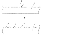
図1は、上側が通常金属製のプレスシート1の部分断面図である。加工するべき表面2は加工前に製造方法に応じて普通の表面粗さ3を備えている。プレスシート1の事前洗浄完了後、発明に従ったレーザー方法で表面構造4が生成され、この表面構造の盛り上がった範囲5及び深さのある範囲6は下側の部分図に示されている。盛り上がった範囲5も深さのある範囲6も、さらに微細構造化7を備えている。プレスシート1の表面の全体の構造化は、発明に従ったレーザー方法を使用して生成され、その際合焦装置 (レーザー光学素子)を適切に制御することによってレーザービームが深みで合焦される。その上、レーザーアセンブリがプレスシート1に対して移動される前に、合焦装置を使用してプレスシートの特定の部分範囲の把握が加工のために行われる。図1は、微細構造化7及び粗構造化を示している。これらの構造化は明確化のために模式的に示されるが、その際に深さプロフィルは最大250μm、好ましくは100μmの寸法で形成されることを前提としている。 FIG. 1 is a partial sectional view of a press sheet 1 whose upper side is usually made of metal. The surface 2 to be processed has a normal surface roughness 3 according to the manufacturing method before processing. After the pre-cleaning of the press sheet 1 is completed, a surface structure 4 is produced with the laser method according to the invention, the raised area 5 and the deep area 6 of this surface structure being shown in the lower partial view. The raised area 5 and the deep area 6 are further provided with a microstructure 7. The entire structuring of the surface of the press sheet 1 is generated using the laser method according to the invention, in which the laser beam is focused in depth by appropriately controlling the focusing device (laser optical element). The Moreover, before the laser assembly is moved relative to the press sheet 1, a specific partial area of the press sheet is grasped for processing using a focusing device. FIG. 1 shows a microstructure 7 and a coarse structure. These structurings are shown schematically for the sake of clarity, assuming that the depth profile is formed with dimensions of up to 250 μm, preferably 100 μm.
図2は本発明の方法を適用するための装置101の平面図である。この装置は、多数の個々の平坦面103から作られた支持面104を備えた1つの支持台102から構成されており、支持台の上にはプレスシート105が載せられる。平坦面103にはそれぞれ1つの吸引開口部106が形成されており、吸引開口部106が図示していない真空ポンプを使用してプレスシート105を平坦面103上に引きつけ、それによって作業プロセス中にプレスシート105の位置がずれないよう確保している。
FIG. 2 is a plan view of an
示された実施例には装置101が水平位置に配置されているが、プレスシート105を加工するためにこれを垂直位置又は垂直に対して傾いた位置に配置することが簡単にできる。プレスシート105の最も長い伸長部に沿ってガイドレール107、108が形成され、その上を駆動モータ111、112を使用してスライドガイド109、110に沿って移動可能であり、駆動モータ111、112は制御装置113、好ましくはコンピュータ情報処理支援の制御装置によって制御可能である。駆動モータ111、112を使用して、レーザーアセンブリがX軸及びY軸方向に移動させられる。レーザーアセンブリ114は、1つのレーザー、1つのビームスプレッダー及び1つの合焦装置から構成され、その際必要に応じて、使用されるレーザーの種類によって1つのレーザーレデューサが追加で投入されてよい。レーザーアセンブリ又は必要に応じて1つの座標方向に隣り合って配置されている複数のレーザーを使用して、プレスシート105の表面加工が行われる。本方法をの速度を上げるため、複数のレーザーアセンブリを一列に、つまり1つの座標方向に必要に応じてあらかじめ定義された間隔を空けてこの列上に配置され、レーザーアセンブリはそれぞれ同時にその対応するプレスシート105の表面の部分範囲を加工でき、その結果これに対応した作業時間の時間短縮を伴う最適化を行うことができる。
In the embodiment shown, the
1 プレスシート
2 表面
3 表面粗さ
4 表面構造
5 盛り上がった範囲
6 深さのある範囲
7 微細構造化
101 装置
102 支持台
103 平坦面
104 支持台
105 プレスシート
107 ガイドレール
108 ガイドレール
109 スライドガイド
110 スライドガイド
111 駆動モータ
112 駆動モータ
113 制御装置
114 レーザーアセンブリ
DESCRIPTION OF SYMBOLS 1 Press sheet 2 Surface 3 Surface roughness 4 Surface structure 5 Raised range 6 Depth range 7
Claims (24)
キャプチャーした表面構造の3Dトポグラフィのデジタルデータの準備及び使用、
x座標及びy座標に張られた平面で少なくとも1つの前記レーザーの位置制御を行うための前記デジタルデータの使用、
少なくとも1つのレーザービームを使用して前記表面の一部除去、
前記表面の一部除去を所定の深さにするために、前記レーザービームの合焦を変化させ、前記合焦を変化させるために、前記3Dトポグラフィのデジタルデータのz座標の使用、
を含む前記表面構造を製造するための方法。 In a method for producing a surface structure of a metal press sheet (1), endless belt or cylindrical embossing roll using at least one laser, the following steps are performed to replicate a predefinable surface structure:
Preparation and use of digital data of 3D topography of captured surface structures;
Use of the digital data for controlling the position of at least one of said laser with a plane stretched in the x and y coordinates,
Removing a portion of the surface using at least one laser beam;
Using the z-coordinate of the digital data of the 3D topography to change the focus of the laser beam to change the focus to a predetermined depth of partial removal of the surface ;
A method for manufacturing the surface structure comprising:
The method for producing a surface structure according to any one of claims 1 to 6, wherein a fiber laser having an energy of 5W to 500W is used as the laser.
Wherein the boundary of the partial region is determined to match the raw range of surfaces, a method for producing a surface structure according to claim 12.
14. A method for manufacturing a surface structure according to claim 12 or 13, characterized in that the determined subrange is an edge length of 10 to 800 cm , depending on the laser used.
19. A method for manufacturing a surface structure according to any one of the preceding claims, characterized by the conversion of captured digital data by interpolation and data reduction for controlling laser optics .
The method according to claim 20 or 21, characterized in that the focusing device is arranged at a distance of 10 cm to 100 cm with respect to the surface, and one surface comprises an edge length of 10 cm to 800 cm. Device for applying.
24. Manufactured according to the method of any one of claims 1 to 19 , or according to any one of claims 20 to 23, for pressing and / or embossing a material plate with a structured surface. Use of press sheets (1), endless belts or cylindrical embossing rolls produced with the apparatus described in 1.
Applications Claiming Priority (2)
| Application Number | Priority Date | Filing Date | Title |
|---|---|---|---|
| EP09010921.6 | 2009-08-26 | ||
| EP09010921A EP2289708B1 (en) | 2009-08-26 | 2009-08-26 | Method for producing a surface structure of a metallic pressed sheet, continuous ribbon or embossing roller |
Publications (2)
| Publication Number | Publication Date |
|---|---|
| JP2011079300A JP2011079300A (en) | 2011-04-21 |
| JP5487397B2 true JP5487397B2 (en) | 2014-05-07 |
Family
ID=42111629
Family Applications (1)
| Application Number | Title | Priority Date | Filing Date |
|---|---|---|---|
| JP2010187911A Active JP5487397B2 (en) | 2009-08-26 | 2010-08-25 | Method for producing the surface structure of a metal press sheet, endless belt or embossing roll, apparatus for applying the method, and use of the produced press sheet, endless belt or cylindrical embossing roll |
Country Status (13)
| Country | Link |
|---|---|
| US (1) | US9446622B2 (en) |
| EP (1) | EP2289708B1 (en) |
| JP (1) | JP5487397B2 (en) |
| CN (1) | CN102049956B (en) |
| AT (1) | ATE538946T1 (en) |
| CA (1) | CA2713817C (en) |
| DK (1) | DK2289708T3 (en) |
| ES (1) | ES2377277T3 (en) |
| PL (1) | PL2289708T3 (en) |
| PT (1) | PT2289708E (en) |
| RS (1) | RS52165B (en) |
| RU (1) | RU2568634C2 (en) |
| SI (1) | SI2289708T1 (en) |
Families Citing this family (40)
| Publication number | Priority date | Publication date | Assignee | Title |
|---|---|---|---|---|
| EP2626216B1 (en) * | 2011-03-10 | 2018-07-11 | HUECK Rheinische GmbH | Method for processing a structured surface of an embossing tool and the embossing tool |
| FR2974758B1 (en) | 2011-05-04 | 2014-05-02 | Commissariat Energie Atomique | DEVICE AND METHOD FOR ENGRAVING A PATTERN |
| DE102011079083A1 (en) * | 2011-07-13 | 2013-01-17 | Trumpf Werkzeugmaschinen Gmbh + Co. Kg | Method for processing a workpiece and a machining device |
| US10183318B2 (en) * | 2011-09-23 | 2019-01-22 | Boegli-Gravures S.A. | Method and device for producing a structured surface on a steel embossing roller |
| DE102012100915A1 (en) * | 2012-02-03 | 2013-08-22 | Sandvik Surface Solutions Division Of Sandvik Materials Technology Deutschland Gmbh | Method for producing etch-resistant structures |
| JP5849821B2 (en) * | 2012-03-29 | 2016-02-03 | 大日本印刷株式会社 | Shadow unevenness removal apparatus, shadow unevenness removal method, and program |
| EP2679402B1 (en) * | 2012-06-26 | 2015-08-05 | Hueck Rheinische GmbH | Method for producing a surface structure with a pressurized water jet |
| DE102012107827A1 (en) * | 2012-08-24 | 2014-02-27 | Sandvik Surface Solutions Division Of Sandvik Materials Technology Deutschland Gmbh | Method for producing gloss effects on pressing tools |
| ES2661954T3 (en) * | 2012-11-07 | 2018-04-04 | Akzenta Paneele + Profile Gmbh | Procedure for the manufacture of a decorated wall or floor panel |
| DE102013010160A1 (en) * | 2013-06-19 | 2015-01-08 | Hueck Rheinische Gmbh | Process for producing a material plate by means of a press plate or endless belt, and press plate or endless belt and material plate |
| EP2839970B1 (en) * | 2013-08-21 | 2017-11-01 | Hueck Rheinische GmbH | Method for producing a hydrophobic or superhydrophobic surface topography |
| PL2848424T3 (en) * | 2013-09-13 | 2020-05-18 | Hueck Rheinische Gmbh | Method for producing a surface structure on a pressing tool by the application of metal coatings |
| DE102014210798A1 (en) | 2014-06-05 | 2015-12-17 | Fraunhofer-Gesellschaft zur Förderung der angewandten Forschung e.V. | Mold, process for its manufacture and use, and plastic film and plastic component |
| EP3047932B1 (en) | 2015-01-21 | 2018-12-26 | Agie Charmilles New Technologies SA | Method of laser ablation for engraving of a surface with patch optimization, with corresponding software and machine tool |
| US10563309B1 (en) | 2015-10-13 | 2020-02-18 | Kings Mountain International, Inc. | Method for creating a textured press plate |
| DE202015007762U1 (en) | 2015-11-10 | 2016-01-18 | Rolf Espe | Press tool formed as a press plate, which consists of a non-metallic material |
| CN106881525B (en) * | 2015-12-15 | 2019-06-18 | 新代科技股份有限公司 | Laser machine control system and its control method |
| KR20180104633A (en) * | 2016-01-22 | 2018-09-21 | 타타 스틸 네덜란드 테크날러지 베.뷔. | Laser texturing of steel strips |
| DE102017206082A1 (en) * | 2017-04-10 | 2018-10-11 | Siemens Aktiengesellschaft | Mold for producing surface-structured components made of a ceramic fiber composite material and method for its production and component of a ceramic fiber composite material |
| EP3421168B1 (en) * | 2017-06-29 | 2022-11-16 | GF Machining Solutions AG | Method for defining a sequence of relative positionings of a laser head in relation to a part ; method for machining a surface of a part by a laser using such method for defining ; corresponding computer program product and storage medium |
| CN107649563B (en) * | 2017-09-19 | 2019-06-07 | 浙江康家宝炊具有限公司 | The production method of cookware outer surface decorative pattern and the pot of application this method manufacture |
| CN107521276A (en) * | 2017-10-11 | 2017-12-29 | 苏州富通高新材料科技股份有限公司 | A kind of sheet material exterior trim machine |
| CN108857110A (en) * | 2018-09-29 | 2018-11-23 | 柯丁宁 | A kind of anti-collision device of laser cutting machine |
| DE102019121861A1 (en) * | 2019-08-14 | 2021-02-18 | Hueck Rheinische Gmbh | Method and device for producing a pressing tool |
| DE102019124004A1 (en) | 2019-09-06 | 2021-03-11 | Hueck Rheinische Gmbh | Press tool, workpiece, method for producing a pressing tool and method for producing a workpiece |
| CN110893556B (en) * | 2019-11-23 | 2021-04-20 | 上海永茂泰汽车零部件有限公司 | Multifunctional milling machine and control method thereof |
| CN111702326B (en) * | 2020-06-18 | 2022-03-25 | 青岛自贸激光科技有限公司 | Laser surface processing method and system |
| CN111850640A (en) * | 2020-07-10 | 2020-10-30 | 张麟敏 | Electroplated dark chromium layer surface structured metal pressing plate and preparation method thereof |
| CN112894144A (en) * | 2020-12-25 | 2021-06-04 | 瓯锟科技温州有限公司 | Metal plate strip texturing device based on laser and texturing method thereof |
| CN112829501A (en) * | 2021-02-01 | 2021-05-25 | 夏前兵 | Stone-like coating relief processing technology |
| CN112895700A (en) * | 2021-02-01 | 2021-06-04 | 夏前兵 | Surface treatment system for paper printing |
| CN112934588A (en) * | 2021-02-01 | 2021-06-11 | 夏前兵 | Automatic processing system for surface texture of stone-like coating |
| CN113001038B (en) * | 2021-03-05 | 2022-11-25 | 赣州市恒邦金属制品有限公司 | Laser cutting device with function is collected to sweeps |
| CN113714648A (en) * | 2021-07-09 | 2021-11-30 | 上海交通大学 | Ship part laser coding system and method |
| DE102021131839B4 (en) * | 2021-12-02 | 2023-11-23 | Hueck Rheinische Gmbh | Method for producing a pressing tool with deep structuring |
| EP4286160A1 (en) * | 2022-06-03 | 2023-12-06 | Gravion GmbH & Co. KG | Embossing roll |
| DE102022116424A1 (en) | 2022-06-30 | 2024-01-04 | Hueck Rheinische Gmbh | Pressing tool for pressing material panels in heating presses |
| DE102022116423A1 (en) | 2022-06-30 | 2024-01-04 | Hueck Rheinische Gmbh | Pressing tool and method for producing a pressing tool |
| CN116021167A (en) * | 2023-03-07 | 2023-04-28 | 苏州天准科技股份有限公司 | LDI etching equipment suitable for large-size product |
| CN116275536B (en) * | 2023-03-16 | 2024-03-12 | 中船重工安谱(湖北)仪器有限公司 | Chip silk screen removing device and method |
Family Cites Families (30)
| Publication number | Priority date | Publication date | Assignee | Title |
|---|---|---|---|---|
| US4987443A (en) * | 1990-04-03 | 1991-01-22 | Sawyer Jr Sterling S | Method and apparatus for imaging press plates |
| DE4033230A1 (en) * | 1990-10-19 | 1992-04-23 | Hueck Fa E | Surface textures on metal press platens - are produced on plates or endless bands by subjecting surface to laser beam, controlling platen movements and beam intensity by computer |
| US5124524A (en) * | 1990-11-15 | 1992-06-23 | Laser Design Inc. | Laser alignment and control system |
| JPH08152430A (en) * | 1994-11-29 | 1996-06-11 | Seiko Instr Inc | Microscope with aligning function |
| EP0734827A1 (en) * | 1995-03-28 | 1996-10-02 | Saueressig Gmbh & Co. | Embossing tools for treating materials with a tacky surface during the forming process |
| US5880430A (en) * | 1995-08-11 | 1999-03-09 | Wein; Joseph H. | Method and apparatus for laser engraving |
| JPH09141385A (en) * | 1995-11-15 | 1997-06-03 | Toyota Motor Corp | Lamination molding method for sand casting mold and production of casting by using the same |
| CN2247070Y (en) * | 1995-12-07 | 1997-02-12 | 中国科学院力学研究所 | Numerically controlled laser graphic machining system |
| US5916461A (en) * | 1997-02-19 | 1999-06-29 | Technolines, Llc | System and method for processing surfaces by a laser |
| US6801334B1 (en) * | 1998-05-28 | 2004-10-05 | Fuji Photo Film Co., Ltd. | Index print producing method, image processing system, image processing method and image processing device |
| JP2001314984A (en) * | 2000-05-01 | 2001-11-13 | Rofin Marubeni Laser Kk | Marking method for metal mold by laser and apparatus therefor |
| RU2177881C1 (en) * | 2000-09-25 | 2002-01-10 | Общество с ограниченной ответственностью "Лазер График" | Method and device for formation of preset image inside the transparent solid material by means of pulsed laser beam |
| DE10148759B8 (en) * | 2000-10-02 | 2005-06-30 | Laser 2000 Gmbh | A method of producing a laser engraving in a surface of a substrate |
| DE10110922B4 (en) * | 2001-03-07 | 2004-08-05 | Benecke-Kaliko Ag | Process for the preparation of an embossing roll of silicone rubber for continuously embossing the surface of a thermoplastic film |
| US6664498B2 (en) * | 2001-12-04 | 2003-12-16 | General Atomics | Method and apparatus for increasing the material removal rate in laser machining |
| DE10202752B4 (en) * | 2002-01-25 | 2004-09-23 | Benecke-Kaliko Ag | Process for producing a molded part which is deep-drawn from a thermoplastic film and embossing roller for embossing the surface of a thermoplastic film intended for deep-drawing purposes |
| US6617543B1 (en) * | 2002-04-11 | 2003-09-09 | Shih-Sheng Yang | Method of making pattern for decorative piece |
| US6787734B2 (en) * | 2002-07-25 | 2004-09-07 | Matsushita Electric Industrial Co., Ltd. | System and method of laser drilling using a continuously optimized depth of focus |
| DE60327206D1 (en) * | 2002-07-25 | 2009-05-28 | Panasonic Corp | Laser drilling system and method using a continuously optimized sharpness |
| IL161904A0 (en) * | 2004-05-10 | 2005-11-20 | Starboard Technologies Ltd | |
| DE102004041434B4 (en) * | 2004-08-27 | 2013-10-10 | Credit Card Supplies | Method for producing a embossing plate for a hot-cold laminating press with three-dimensional structures |
| JP2008515643A (en) * | 2004-10-07 | 2008-05-15 | パワーレイズ・リミテッド | Hard material processing apparatus and processing method using laser having irradiance in the range of 106 to 109 Wcm-2 and repetition rate in the range of 10 to 50 kHz |
| EP1650839A1 (en) * | 2004-10-20 | 2006-04-26 | Wavelight Laser Technologie AG | Fiber laser arrangement |
| JP2006168260A (en) * | 2004-12-17 | 2006-06-29 | Kofu Casio Co Ltd | Manufacturing method of mold for molding light guide plate, mold for molding light guide plate, and light guide plate |
| GB2421477B (en) * | 2004-12-24 | 2008-02-27 | Sara Lee Corp | A method and apparatus for shaping of fabrics |
| JP2006224107A (en) * | 2005-02-15 | 2006-08-31 | Mitsubishi Electric Corp | Method and apparatus of laser beam machining |
| ATE446159T1 (en) * | 2005-05-31 | 2009-11-15 | Trumpf Werkzeugmaschinen Gmbh | LASER PROCESSING MACHINE WITH LASER PROCESSING NOZZLE ADJUSTMENT FOR ALIGNING THE LASER BEAM WITH THE LASER PROCESSING NOZZLE HOLE |
| EP1964622B1 (en) * | 2005-12-13 | 2013-01-23 | NGK Insulators, Ltd. | Method of forming an image pattern on surface of a metallic glass member |
| JP5000247B2 (en) * | 2006-09-25 | 2012-08-15 | 富士フイルム株式会社 | Imaging lens |
| DE102006051658A1 (en) * | 2006-11-02 | 2008-05-08 | Mitsubishi Polyester Film Gmbh | Multilayer, white, laser-cut polyester film |
-
2009
- 2009-08-26 AT AT09010921T patent/ATE538946T1/en active
- 2009-08-26 PL PL09010921T patent/PL2289708T3/en unknown
- 2009-08-26 SI SI200930196T patent/SI2289708T1/en unknown
- 2009-08-26 PT PT09010921T patent/PT2289708E/en unknown
- 2009-08-26 RS RS20120092A patent/RS52165B/en unknown
- 2009-08-26 DK DK09010921.6T patent/DK2289708T3/en active
- 2009-08-26 ES ES09010921T patent/ES2377277T3/en active Active
- 2009-08-26 EP EP09010921A patent/EP2289708B1/en active Active
-
2010
- 2010-08-25 JP JP2010187911A patent/JP5487397B2/en active Active
- 2010-08-25 CA CA2713817A patent/CA2713817C/en active Active
- 2010-08-26 RU RU2010135970/12A patent/RU2568634C2/en active
- 2010-08-26 US US12/807,066 patent/US9446622B2/en active Active
- 2010-08-26 CN CN201010511156.8A patent/CN102049956B/en active Active
Also Published As
| Publication number | Publication date |
|---|---|
| RU2010135970A (en) | 2012-03-10 |
| CA2713817A1 (en) | 2011-02-26 |
| PL2289708T3 (en) | 2012-05-31 |
| DK2289708T3 (en) | 2012-02-27 |
| ATE538946T1 (en) | 2012-01-15 |
| JP2011079300A (en) | 2011-04-21 |
| CN102049956A (en) | 2011-05-11 |
| SI2289708T1 (en) | 2012-04-30 |
| CA2713817C (en) | 2017-04-11 |
| EP2289708B1 (en) | 2011-12-28 |
| EP2289708A1 (en) | 2011-03-02 |
| US9446622B2 (en) | 2016-09-20 |
| RS52165B (en) | 2012-08-31 |
| PT2289708E (en) | 2012-01-24 |
| RU2568634C2 (en) | 2015-11-20 |
| CN102049956B (en) | 2014-11-19 |
| US20110048254A1 (en) | 2011-03-03 |
| ES2377277T3 (en) | 2012-03-26 |
Similar Documents
| Publication | Publication Date | Title |
|---|---|---|
| JP5487397B2 (en) | Method for producing the surface structure of a metal press sheet, endless belt or embossing roll, apparatus for applying the method, and use of the produced press sheet, endless belt or cylindrical embossing roll | |
| KR102187168B1 (en) | Method for producing a hydrophobic or superhydrophobic surface topography | |
| JP6495898B2 (en) | Method and apparatus for forming a three-dimensional surface structure of a press tool | |
| JP5544623B2 (en) | Method for machining a structured surface | |
| CA2865974C (en) | Method for producing a surface structure with a water-jet device | |
| CN103231619A (en) | Preparation equipment for large-size fine embossed metal plate | |
| JP2011521805A5 (en) | ||
| CN111215765B (en) | Processing method for processing precise photosensitive hole by ultraviolet laser and laser equipment | |
| CN102091863B (en) | Laser processing device and laser processing method | |
| CN114535812B (en) | Laser direct writing-laser scanning induction cooperative method for surface of sheet micropore group | |
| JP2011125867A (en) | Laser beam machining method | |
| JP3212033U (en) | Engraving equipment | |
| CN109061949A (en) | The production method of alignment film printing version | |
| CN101987554B (en) | Laser engraving device | |
| Booth et al. | Laser micromachining techniques for industrial MEMS applications | |
| JP2004148329A (en) | Processing roll manufacturing method, and processing roll | |
| RU2561904C2 (en) | Method of obtaining wide-format art drawing on front surface of natural leather using laser engraving machine | |
| KR20060119609A (en) | Laser marking device of mask moving type | |
| JP2011020347A (en) | Ultrasonic machining device | |
| JPS63192583A (en) | Laser engraving method | |
| KR20080067908A (en) | Laser marking device of mask moving type |
Legal Events
| Date | Code | Title | Description |
|---|---|---|---|
| A521 | Request for written amendment filed |
Free format text: JAPANESE INTERMEDIATE CODE: A523 Effective date: 20110818 |
|
| A977 | Report on retrieval |
Free format text: JAPANESE INTERMEDIATE CODE: A971007 Effective date: 20120426 |
|
| A131 | Notification of reasons for refusal |
Free format text: JAPANESE INTERMEDIATE CODE: A131 Effective date: 20120515 |
|
| A601 | Written request for extension of time |
Free format text: JAPANESE INTERMEDIATE CODE: A601 Effective date: 20120813 |
|
| A602 | Written permission of extension of time |
Free format text: JAPANESE INTERMEDIATE CODE: A602 Effective date: 20120820 |
|
| A521 | Request for written amendment filed |
Free format text: JAPANESE INTERMEDIATE CODE: A523 Effective date: 20120913 |
|
| A131 | Notification of reasons for refusal |
Free format text: JAPANESE INTERMEDIATE CODE: A131 Effective date: 20130402 |
|
| A521 | Request for written amendment filed |
Free format text: JAPANESE INTERMEDIATE CODE: A523 Effective date: 20130610 |
|
| TRDD | Decision of grant or rejection written | ||
| A01 | Written decision to grant a patent or to grant a registration (utility model) |
Free format text: JAPANESE INTERMEDIATE CODE: A01 Effective date: 20131224 |
|
| A61 | First payment of annual fees (during grant procedure) |
Free format text: JAPANESE INTERMEDIATE CODE: A61 Effective date: 20140123 |
|
| R150 | Certificate of patent or registration of utility model |
Ref document number: 5487397 Country of ref document: JP Free format text: JAPANESE INTERMEDIATE CODE: R150 |
|
| R250 | Receipt of annual fees |
Free format text: JAPANESE INTERMEDIATE CODE: R250 |
|
| R250 | Receipt of annual fees |
Free format text: JAPANESE INTERMEDIATE CODE: R250 |
|
| R250 | Receipt of annual fees |
Free format text: JAPANESE INTERMEDIATE CODE: R250 |
|
| R250 | Receipt of annual fees |
Free format text: JAPANESE INTERMEDIATE CODE: R250 |
|
| R250 | Receipt of annual fees |
Free format text: JAPANESE INTERMEDIATE CODE: R250 |
|
| R250 | Receipt of annual fees |
Free format text: JAPANESE INTERMEDIATE CODE: R250 |
|
| R250 | Receipt of annual fees |
Free format text: JAPANESE INTERMEDIATE CODE: R250 |
|
| R250 | Receipt of annual fees |
Free format text: JAPANESE INTERMEDIATE CODE: R250 |