JP5485286B2 - Endoscopic end cap for suturing tissue - Google Patents
Endoscopic end cap for suturing tissue Download PDFInfo
- Publication number
- JP5485286B2 JP5485286B2 JP2011534660A JP2011534660A JP5485286B2 JP 5485286 B2 JP5485286 B2 JP 5485286B2 JP 2011534660 A JP2011534660 A JP 2011534660A JP 2011534660 A JP2011534660 A JP 2011534660A JP 5485286 B2 JP5485286 B2 JP 5485286B2
- Authority
- JP
- Japan
- Prior art keywords
- tissue
- side wall
- medical device
- distal
- interior space
- Prior art date
- Legal status (The legal status is an assumption and is not a legal conclusion. Google has not performed a legal analysis and makes no representation as to the accuracy of the status listed.)
- Active
Links
- 238000004891 communication Methods 0.000 claims description 5
- 238000001125 extrusion Methods 0.000 claims description 5
- 239000000463 material Substances 0.000 claims description 4
- 210000001519 tissue Anatomy 0.000 description 92
- 238000000034 method Methods 0.000 description 22
- 238000010586 diagram Methods 0.000 description 8
- 210000001035 gastrointestinal tract Anatomy 0.000 description 6
- 238000012800 visualization Methods 0.000 description 6
- 229920003023 plastic Polymers 0.000 description 5
- 239000004033 plastic Substances 0.000 description 5
- 210000002784 stomach Anatomy 0.000 description 4
- 238000012986 modification Methods 0.000 description 3
- 230000004048 modification Effects 0.000 description 3
- 210000000214 mouth Anatomy 0.000 description 3
- 230000003287 optical effect Effects 0.000 description 3
- 238000001356 surgical procedure Methods 0.000 description 3
- 241001465754 Metazoa Species 0.000 description 2
- 210000003484 anatomy Anatomy 0.000 description 2
- 210000000436 anus Anatomy 0.000 description 2
- 230000008878 coupling Effects 0.000 description 2
- 238000010168 coupling process Methods 0.000 description 2
- 238000005859 coupling reaction Methods 0.000 description 2
- 229920001971 elastomer Polymers 0.000 description 2
- 239000004744 fabric Substances 0.000 description 2
- 210000003736 gastrointestinal content Anatomy 0.000 description 2
- 208000015181 infectious disease Diseases 0.000 description 2
- 210000000056 organ Anatomy 0.000 description 2
- 210000001215 vagina Anatomy 0.000 description 2
- 241000894006 Bacteria Species 0.000 description 1
- 239000004698 Polyethylene Substances 0.000 description 1
- 230000003187 abdominal effect Effects 0.000 description 1
- NIXOWILDQLNWCW-UHFFFAOYSA-N acrylic acid group Chemical group C(C=C)(=O)O NIXOWILDQLNWCW-UHFFFAOYSA-N 0.000 description 1
- 239000000853 adhesive Substances 0.000 description 1
- 230000001070 adhesive effect Effects 0.000 description 1
- 238000001574 biopsy Methods 0.000 description 1
- 210000004204 blood vessel Anatomy 0.000 description 1
- 210000001124 body fluid Anatomy 0.000 description 1
- 239000010839 body fluid Substances 0.000 description 1
- 210000004534 cecum Anatomy 0.000 description 1
- 210000005069 ears Anatomy 0.000 description 1
- 239000000806 elastomer Substances 0.000 description 1
- 210000003238 esophagus Anatomy 0.000 description 1
- 239000012530 fluid Substances 0.000 description 1
- 230000036512 infertility Effects 0.000 description 1
- 210000000936 intestine Anatomy 0.000 description 1
- 238000002357 laparoscopic surgery Methods 0.000 description 1
- 230000014759 maintenance of location Effects 0.000 description 1
- 210000001331 nose Anatomy 0.000 description 1
- 210000003200 peritoneal cavity Anatomy 0.000 description 1
- 229920001643 poly(ether ketone) Polymers 0.000 description 1
- 229920000058 polyacrylate Polymers 0.000 description 1
- 229920002239 polyacrylonitrile Polymers 0.000 description 1
- -1 polyethylene Polymers 0.000 description 1
- 229920000573 polyethylene Polymers 0.000 description 1
- 229920000642 polymer Polymers 0.000 description 1
- 229920000915 polyvinyl chloride Polymers 0.000 description 1
- 239000004800 polyvinyl chloride Substances 0.000 description 1
- 230000002265 prevention Effects 0.000 description 1
- 238000011084 recovery Methods 0.000 description 1
- 239000005060 rubber Substances 0.000 description 1
- 238000009958 sewing Methods 0.000 description 1
- 238000009810 tubal ligation Methods 0.000 description 1
- 238000009423 ventilation Methods 0.000 description 1
Images


Classifications
-
- A—HUMAN NECESSITIES
- A61—MEDICAL OR VETERINARY SCIENCE; HYGIENE
- A61B—DIAGNOSIS; SURGERY; IDENTIFICATION
- A61B17/00—Surgical instruments, devices or methods, e.g. tourniquets
- A61B17/04—Surgical instruments, devices or methods, e.g. tourniquets for suturing wounds; Holders or packages for needles or suture materials
- A61B17/0401—Suture anchors, buttons or pledgets, i.e. means for attaching sutures to bone, cartilage or soft tissue; Instruments for applying or removing suture anchors
-
- A—HUMAN NECESSITIES
- A61—MEDICAL OR VETERINARY SCIENCE; HYGIENE
- A61B—DIAGNOSIS; SURGERY; IDENTIFICATION
- A61B1/00—Instruments for performing medical examinations of the interior of cavities or tubes of the body by visual or photographical inspection, e.g. endoscopes; Illuminating arrangements therefor
- A61B1/00064—Constructional details of the endoscope body
- A61B1/00071—Insertion part of the endoscope body
- A61B1/0008—Insertion part of the endoscope body characterised by distal tip features
- A61B1/00087—Tools
-
- A—HUMAN NECESSITIES
- A61—MEDICAL OR VETERINARY SCIENCE; HYGIENE
- A61B—DIAGNOSIS; SURGERY; IDENTIFICATION
- A61B1/00—Instruments for performing medical examinations of the interior of cavities or tubes of the body by visual or photographical inspection, e.g. endoscopes; Illuminating arrangements therefor
- A61B1/012—Instruments for performing medical examinations of the interior of cavities or tubes of the body by visual or photographical inspection, e.g. endoscopes; Illuminating arrangements therefor characterised by internal passages or accessories therefor
- A61B1/018—Instruments for performing medical examinations of the interior of cavities or tubes of the body by visual or photographical inspection, e.g. endoscopes; Illuminating arrangements therefor characterised by internal passages or accessories therefor for receiving instruments
-
- A—HUMAN NECESSITIES
- A61—MEDICAL OR VETERINARY SCIENCE; HYGIENE
- A61B—DIAGNOSIS; SURGERY; IDENTIFICATION
- A61B17/00—Surgical instruments, devices or methods, e.g. tourniquets
- A61B17/04—Surgical instruments, devices or methods, e.g. tourniquets for suturing wounds; Holders or packages for needles or suture materials
- A61B17/0487—Suture clamps, clips or locks, e.g. for replacing suture knots; Instruments for applying or removing suture clamps, clips or locks
-
- A—HUMAN NECESSITIES
- A61—MEDICAL OR VETERINARY SCIENCE; HYGIENE
- A61B—DIAGNOSIS; SURGERY; IDENTIFICATION
- A61B17/00—Surgical instruments, devices or methods, e.g. tourniquets
- A61B17/00234—Surgical instruments, devices or methods, e.g. tourniquets for minimally invasive surgery
- A61B2017/00292—Surgical instruments, devices or methods, e.g. tourniquets for minimally invasive surgery mounted on or guided by flexible, e.g. catheter-like, means
- A61B2017/00296—Surgical instruments, devices or methods, e.g. tourniquets for minimally invasive surgery mounted on or guided by flexible, e.g. catheter-like, means mounted on an endoscope
-
- A—HUMAN NECESSITIES
- A61—MEDICAL OR VETERINARY SCIENCE; HYGIENE
- A61B—DIAGNOSIS; SURGERY; IDENTIFICATION
- A61B17/00—Surgical instruments, devices or methods, e.g. tourniquets
- A61B17/04—Surgical instruments, devices or methods, e.g. tourniquets for suturing wounds; Holders or packages for needles or suture materials
- A61B17/0401—Suture anchors, buttons or pledgets, i.e. means for attaching sutures to bone, cartilage or soft tissue; Instruments for applying or removing suture anchors
- A61B2017/0409—Instruments for applying suture anchors
-
- A—HUMAN NECESSITIES
- A61—MEDICAL OR VETERINARY SCIENCE; HYGIENE
- A61B—DIAGNOSIS; SURGERY; IDENTIFICATION
- A61B17/00—Surgical instruments, devices or methods, e.g. tourniquets
- A61B17/04—Surgical instruments, devices or methods, e.g. tourniquets for suturing wounds; Holders or packages for needles or suture materials
- A61B17/0401—Suture anchors, buttons or pledgets, i.e. means for attaching sutures to bone, cartilage or soft tissue; Instruments for applying or removing suture anchors
- A61B2017/0417—T-fasteners
Landscapes
- Health & Medical Sciences (AREA)
- Life Sciences & Earth Sciences (AREA)
- Surgery (AREA)
- General Health & Medical Sciences (AREA)
- Public Health (AREA)
- Veterinary Medicine (AREA)
- Nuclear Medicine, Radiotherapy & Molecular Imaging (AREA)
- Animal Behavior & Ethology (AREA)
- Molecular Biology (AREA)
- Engineering & Computer Science (AREA)
- Biomedical Technology (AREA)
- Heart & Thoracic Surgery (AREA)
- Medical Informatics (AREA)
- Biophysics (AREA)
- Radiology & Medical Imaging (AREA)
- Physics & Mathematics (AREA)
- Pathology (AREA)
- Optics & Photonics (AREA)
- Rheumatology (AREA)
- Surgical Instruments (AREA)
Description
本発明は、概括的には、組織を縫合するための医療システム、装置及び方法に、より具体的には、組織の開口部を内視鏡を使用して縫合することに関する。 The present invention relates generally to medical systems, devices, and methods for suturing tissue, and more specifically to suturing an opening in tissue using an endoscope.
臓器及び血管の壁には、開口部又は穿孔が自然に生じ、又は意図的に若しくは無意図的に形成し得る。これらの開口部は、身体の隣接臓器へのアクセスを得るために使用することができ、そのような技法は一般に経管腔的処置と呼ばれている。例えば、70年以上も前にクルドスコピーが開発されており、同技法は盲嚢に開口部を形成することによって経膣的に腹膜腔にアクセスすることを伴う。このアクセスは、医療専門家が、数多くの解剖学的構造を目視で調べられるようにすると共に、バイオプシー又は卵管結紮の様な他の手術など、各種処置を施すことができる。他の体内管腔を使って様々な体腔へのアクセスを得るための数多くの経管腔的処置も開発されている。口、鼻、耳、肛門又は膣などの自然開口部はそのような体内管腔及び空洞へのアクセスを提供できる。消化管の体内管腔は多くは内視鏡的に診察され、すべて低侵襲的なやり方で、腹膜腔及び他の体腔へのアクセスを提供するのに利用できる。 Openings or perforations occur naturally in the walls of organs and blood vessels, or can be intentionally or unintentionally formed. These openings can be used to gain access to adjacent organs of the body, and such techniques are commonly referred to as transluminal procedures. For example, Kurdscopy has been developed more than 70 years ago, and the technique involves transvaginally accessing the peritoneal cavity by forming an opening in the cecum. This access allows medical professionals to visually examine numerous anatomical structures and perform various procedures such as biopsy or other surgeries such as tubal ligation. A number of transluminal procedures have also been developed to gain access to various body cavities using other body lumens. Natural openings such as the mouth, nose, ears, anus or vagina can provide access to such body lumens and cavities. The body lumen of the gastrointestinal tract is often examined endoscopically and can be used to provide access to the peritoneal and other body cavities, all in a minimally invasive manner.
従来の観血的手術又は腹腔鏡下手術と比べて、経腔的処置は、腹部切開(又は他の外部切開)及び合併症につながる切開を排除することにより、より低侵襲となり、また、術後回復時間を短縮し、痛みを減少させ、外見を改善する。その一方で、開口部及び体腔への適当な導管を提供すること、該導管を通して操作でき且つ体腔内で操作できる堅牢な医療装置、導管の不稔性、体腔への通気の維持、開口部の適切な閉合、及び感染の防止などの経腔的処置への課題が残っている。例えば、開口部が胃又は腸の様な消化管の体壁に形成されるとき、胃の内容物、腸の内容物又は他の体液が隣接する体腔内へなだれ込む事態を起こす可能性がある。細菌を含んだ液が消化管の外へ移動すると、望まれない、また場合によっては致死的な感染を引き起こす可能性がある。 Compared to conventional open surgery or laparoscopic surgery, transluminal procedures are less invasive by eliminating abdominal incisions (or other external incisions) and incisions that lead to complications, and surgery Reduce post recovery time, reduce pain and improve appearance. On the other hand, providing an appropriate conduit to the opening and body cavity, a robust medical device that can be manipulated through and within the body cavity, sterility of the conduit, maintaining ventilation to the body cavity, Challenges to transluminal treatment such as proper closure and prevention of infection remain. For example, when an opening is formed in the body wall of the gastrointestinal tract, such as the stomach or intestine, it can cause the stomach contents, intestinal contents or other body fluids to sag into the adjacent body cavity. If the fluid containing bacteria moves out of the digestive tract, it can cause unwanted and sometimes fatal infections.
自然に生じているか、意図的に形成された或いは意図的でなく形成された穿孔を永久に閉合し、また組織が適切に治癒できるようにするために、縫合糸や、接着剤、クリップ、組織アンカーなどを使用して、多くの医療装置及び方法が開発されてきた。そのような装置類の1つは、胃腸管内などの穿孔を内視鏡を使用して閉合することを目的としている。従って、穿孔の閉合を容易にするために内視鏡に取り付ける様々な医療装置が提案されてきた。これらのいくつかの医療装置は、吸引力を使用して、縫合又はアンカー配置のために組織を正しい位置に配置し、他のものは、組織把持具又は他の装置を使用して組織を正しい位置に配置している。 Sutures, adhesives, clips, tissue to permanently close perforations that are naturally occurring, intentionally or unintentionally formed, and to allow the tissue to heal properly Many medical devices and methods have been developed using anchors and the like. One such device is intended to close a perforation, such as in the gastrointestinal tract, using an endoscope. Accordingly, various medical devices have been proposed that are attached to an endoscope to facilitate closure of the perforation. Some of these medical devices use suction to place the tissue in the correct position for suture or anchor placement, others use the tissue grasper or other device to place the tissue correctly. Placed in position.
本発明は組織の穿孔を縫合するための医療装置、システム、及び方法を提供して、内視鏡的に及び/又は腹腔鏡的に使用することができ、且つ該穿孔の完全な閉合のために穿孔の周りに簡単で信頼でき且つ制御可能な縫合糸の配置を提供する。本発明の教示に従って構成されている医療装置の一実施形態は、概ね、組織アンカーを使用して組織の開口部を縫合するための内視鏡で使用するエンドキャップを含んでいる。該エンドキャップは環状の側壁によって画定される管形状を有しており、側壁は内部空間を画定している。側面開口部が、さらに環状の側壁によって画定され、内部空間と連通している。側面開口部は、縫合のために内部空間内で組織を受け入れて配置するサイズである。支持リブが、内部空間内で側面開口部より遠位側に配置されている。該支持リブは、側壁の第1の位置から側壁の第2の位置まで横方向に延在している。支持リブ及び側壁は穿刺穴を画定し、組織アンカーの長さより大きいサイズであって、アンカーが穿刺穴及び側面開口部を通って自由に内部空間を出ることを可能にしている。 The present invention provides medical devices, systems and methods for suturing tissue perforations that can be used endoscopically and / or laparoscopically and for complete closure of the perforations. It provides a simple, reliable and controllable suture arrangement around the perforation. One embodiment of a medical device constructed in accordance with the teachings of the present invention generally includes an end cap for use with an endoscope for suturing a tissue opening using a tissue anchor. The end cap has a tubular shape defined by an annular side wall, and the side wall defines an interior space. A side opening is further defined by the annular side wall and communicates with the interior space. The side openings are sized to receive and place tissue within the interior space for suturing. A support rib is disposed distal to the side opening in the internal space. The support ribs extend laterally from a first position on the side wall to a second position on the side wall. The support ribs and side walls define a puncture hole and are sized larger than the length of the tissue anchor, allowing the anchor to leave the interior space freely through the puncture hole and the side openings.
医療装置のより詳細な態様によると、穿刺穴及び側面開口部は、エンドキャップの同じ側面に位置していて、好ましくは線上で相互に係合している。支持リブは、好ましくは、長手方向に方向付けられ、側面開口部より遠位側の内部空間の部分を二分している。また、エンドキャップは端部壁を有してもよく、そこに支持リブが、端部壁と側壁に沿った第1及び第2の位置の間に延在することが好ましい。好適な構成では、端部壁を通した可視化を可能にする内視鏡に端部壁の大部分が見えるように配置されており、好ましくは、エンドキャップは光学グレードプラスチックで形成される。支持リブのエッジは支持面を画定し、且つ側面開口部によって露出される側壁の一部分と共に、縫合の間、組織を支持するための環状の支持面を画定している。 According to a more detailed aspect of the medical device, the puncture hole and the side opening are located on the same side of the end cap, preferably in line with each other. The support rib is preferably oriented longitudinally and bisects the portion of the interior space distal to the side opening. The end cap may also have an end wall in which support ribs preferably extend between the first and second positions along the end wall and the side wall. In a preferred configuration, an endoscope that allows visualization through the end wall is positioned so that most of the end wall is visible, and preferably the end cap is made of optical grade plastic. The edges of the support ribs define a support surface and, together with a portion of the sidewall exposed by the side opening, define an annular support surface for supporting tissue during suturing.
本発明の教示に従って構成される医療システムの一実施形態は、概括的には、内視鏡、針アセンブリおよびエンドキャップを含んでいる。該内視鏡は長手方向の軸線を画定している作業チャンネルを有している。針アセンブリは遠位端と針のルーメンを画定している針を有している。組織アンカーは該針のルーメン内に摺動可能に収容されており、該組織アンカーに縫合糸が取り付けられている。針アセンブリは内視鏡の作業チャンネル内に摺動可能に収容されている。エンドキャップは、近位の内部空間、中間の内部空間、および遠位の内部空間を画定する環状の側壁を有している。近位の内部空間は、内視鏡の遠位端を収容するサイズである。側壁は、中間の内部空間と連通している側面開口部を画定し、該側面開口部に組織を収容するサイズである。エンドキャップは、遠位の内部空間のアンカー押し出し部を画定するために、環状の側壁と遠位の内部空間を二分する支持リブを含んでいる。アンカー押し出し部は、組織アンカーが長手方向の向きであるとき、該アンカー押し出し部に組織アンカーを収容するサイズである。 One embodiment of a medical system constructed in accordance with the teachings of the present invention generally includes an endoscope, a needle assembly, and an end cap. The endoscope has a working channel that defines a longitudinal axis. The needle assembly has a needle defining a distal end and a needle lumen. A tissue anchor is slidably received within the lumen of the needle and a suture is attached to the tissue anchor. The needle assembly is slidably received in the working channel of the endoscope. The end cap has an annular side wall that defines a proximal interior space, an intermediate interior space, and a distal interior space. The proximal interior space is sized to accommodate the distal end of the endoscope. The side wall is sized to define a side opening in communication with the intermediate interior space and to receive tissue in the side opening. The end cap includes a support rib that bisects the annular sidewall and the distal interior space to define an anchor extrusion in the distal interior space. The anchor push-out portion is sized to accommodate the tissue anchor in the anchor push-out portion when the tissue anchor is in the longitudinal direction.
医療システムのより詳細な態様によると、遠位の内部空間のアンカー押し出し部は内視鏡の作業チャンネルと周方向に並んでいる。遠位の内部空間のアンカー押し出し部は側面開口部と直接連通しており、それらの間には構造体が存在しない。遠位の内部空間の押し出し部と中間の内部空間の間の領域は、好ましくは該領域を通して長手方向の向きで組織アンカーを通過させるサイズである穿刺穴を画定している。 According to a more detailed aspect of the medical system, the distal inner space anchor pusher is circumferentially aligned with the working channel of the endoscope. The anchor extrusion in the distal interior space is in direct communication with the side opening and there is no structure between them. The region between the distal interior space extrusion and the intermediate interior space defines a puncture hole that is preferably sized to pass the tissue anchor through the region in a longitudinal orientation.
また本発明の教示に従って、前述の医療装置及びシステムを利用する組織の開口部を縫合するための方法が提供される。医療装置のエンドキャップは内視鏡の遠位端に取り付けられる。該内視鏡および医療装置は開口部に隣接した第1の部位に導入され、組織がエンドキャップの中間の内部空間内に配置される。針アセンブリは組織と穿刺穴を通して遠位方向に進められる。組織アンカーは遠位の内部空間に配備され、針アセンブリは組織を通して近位方向に引き戻される。次に、組織が中間の内部空間内に留まっている間に、内視鏡および医療装置は開口部の周辺に沿って動かすことができ、それにより、組織アンカーが穿刺穴を通って直接後方に通過して側面開口部から抜け出る。針アセンブリは開口部に隣接した第2の部位において組織を貫通して遠位方向に進められ、第2の組織アンカーが配備される。縫合糸の自由端は、開口部を閉合するために締め付けられる。 Also in accordance with the teachings of the present invention, a method for suturing a tissue opening utilizing the medical devices and systems described above is provided. The end cap of the medical device is attached to the distal end of the endoscope. The endoscope and medical device are introduced into a first site adjacent to the opening and the tissue is placed in an internal space intermediate the end cap. The needle assembly is advanced distally through the tissue and the puncture hole. The tissue anchor is deployed in the distal interior space and the needle assembly is pulled proximally through the tissue. The endoscope and medical device can then be moved along the perimeter of the opening while the tissue remains in the intermediate interior space so that the tissue anchor is directly posteriorly through the puncture hole Pass through the side opening. The needle assembly is advanced distally through the tissue at a second site adjacent to the opening and a second tissue anchor is deployed. The free end of the suture is tightened to close the opening.
当該方法のより詳細な態様によると、縫合糸の自由端は、組織アンカーを相互により近く引き寄せて開口部を閉合するために、近位方向に引く。好ましくは、複数の組織アンカーは1本の縫合糸に結合され、それぞれの組織アンカーは摺動可能に縫合糸に取り付けられる。その結果、該方法はさらに、開口部の周りの複数の組織アンカーを位置決めするステップと、各組織アンカーの間の距離を縮め且つ開口部の周りの組織を押し縮めて開口部を閉合するために、縫合糸の各端部を巾着縫合式に引っ張るステップとを含むことができる。 According to a more detailed aspect of the method, the free ends of the suture are pulled proximally to pull the tissue anchors closer together and close the opening. Preferably, the plurality of tissue anchors are coupled to a single suture and each tissue anchor is slidably attached to the suture. As a result, the method further includes positioning a plurality of tissue anchors around the opening and reducing the distance between each tissue anchor and compressing the tissue around the opening to close the opening. Pulling each end of the suture into a purse string suture.
本明細書の一部に組み入れられ、本明細書の一部を形成する添付図面は、本発明のいくつかの態様を示し、本明細書の記述と共に本発明の原理について説明するのに役立っている。 The accompanying drawings, which are incorporated in and form a part of this specification, illustrate several aspects of the present invention and, together with the description of the specification, serve to explain the principles of the invention. Yes.
本願では、「近位」という用語は医療処置中に概ね医師に向かっている方向を指し、「遠位」という用語は医療処置中に概ね患者の生体構造内の目標部位に向かっている方向を指している。 In this application, the term “proximal” refers to the direction generally toward the physician during the medical procedure, and the term “distal” refers generally to the direction toward the target site within the patient's anatomy during the medical procedure. pointing.
ここで図を見ると、図1と図2は、本発明の教示により構成された、組織12の穿孔10(例えば図6参照)を縫合閉鎖するための医療システム20を示している。一般に、医療システム20は概括的には内視鏡22を備え、針アセンブリ24及び医療装置26が内視鏡22とともに使用するために適用される。内視鏡22は、当業者に既知のどのような内視鏡であってもよく、従って、様々な長さ、直径、及び機能を有することができる。内視鏡22は概ね長手方向の軸線14を画定しており、作業チャンネル28は内視鏡22を通って長手方向に延在している。針アセンブリ24は、作業チャンネル28内に収容され、図2に最も分かり易く示されている様に、針のルーメン32を有する針30を有し、該ルーメンは縫合糸36が接続された1つ以上の組織アンカー34を収容している。当技術分野で知られているように、スタイレット38又は他の押し出し要素が、針のルーメン32内でアンカー34を押し出すのに通常適している。同様に、針のシース40が針30の鋭い遠位先端24の露出を保護及び調整するために備えられてもよい。
Turning now to the figures, FIGS. 1 and 2 illustrate a
医療装置26は、概括的には、内部空間46を画定する管状又は環状の側壁44を有するエンドキャップ42を含み、該内部空間は針アセンブリ24を使用して組織12を縫合するための側面開口部48を通してアクセス可能である。内部空間46の近位部分46pは内視鏡22の遠位端を収容するサイズである。当技術分野で知られているように、エンドキャップ42は、内視鏡22上でのエンドキャップ42の選択的保持のために、内視鏡22と摩擦によって係合する構造とされてもよいが、エンドキャップ42を内視鏡22に結合するための他の手段が使用されてもよい。従って、内視鏡22及び医療装置26は、図に示す結合形態で患者の身体内を通って行き来するようになされている。
The
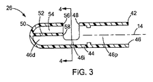
ここで図3と図4を見ると、医療装置26は断面図で示されている。環状の側壁44は内部空間46を画定しており、その部分は近位の内部空間46p、中間の内部空間46i、及び遠位の内部空間46dを含んでいる。中間の内部空間46iに隣接して、側壁44は組織12が内部空間46に入る側面開口部48を画定している。好ましくは、医療装置26は側壁44の遠位端に位置する端部壁50も含んでいる。端部壁50は、遠位の内部空間46dを囲み、内視鏡22が、本明細書により詳細に論じられるエンドキャップ42を通して可視化できる光学グレードプラスチックで構成されることが好ましい。
3 and 4, the
また、医療装置26は遠位の内部空間46dの環状の側壁44を二分する支持リブ52を含んでいる。支持リブ52の一方の側に、遠位の内部空間46dのアンカー押し出し部54があり、該アンカー押し出し部は支持リブ52と側壁44の間の空間によって画定される。遠位の内部空間46dのアンカー押し出し部54は、針アセンブリ24、特に針30及び組織アンカー34を収容するサイズである。図4に最も分かり易く示されている様に、支持リブ52は側壁の第1の位置52aから側壁の第2の位置52bに延在している。従って、また、支持リブ52と側壁44はそれらの間に穿刺穴56を画定し、該穿刺穴はアンカー押し出し部54が中間の内部空間46iと交わる領域である。本明細書でさらに詳細に説明するように、支持リブ52のエッジ58は支持面を画定して、側面開口部48によって露出された側壁の部分と共に、縫合中の組織を支持するための環状の支持面を画定している。アンカー押し出し部54は、線、すなわち側壁44によって画定された穿刺穴56の曲線を挟んで側面開口部48と交わる。
The
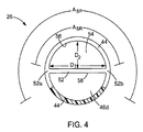
穿刺穴56は半円の形状であり、該形状は(エンドキャップ42の管状又は環状の形状によって決まる他の形状であってもよいが)、最大径D1及び最小径D2によって画定される。好ましくは、最大径D1は(図5に示す)組織アンカー34の長さLAより大きく、最小径D2は組織アンカー34の長さLA未満の大きさである。これは、遠位の内部空間46dのアンカー押し出し部54内に組織アンカー34を正しく配置するのに役立つ。別の実施例では、最大径D1と最小径D2の両方が組織アンカー34の長さLAより大きくてもよい。どちらの場合でも、組織アンカー34が長手方向の向き、即ち、該組織アンカーの軸線37が横向きに延在し、概ね長手方向の軸線14に垂直(即ち、垂線の約15度以内)である向きにある間、遠位の内部空間46dのアンカー押し出し部54は組織アンカー34を受け入れるサイズである。同様に、組織アンカー34は、長手方向の向きで穿刺穴56を貫通することができる。遠位の内部空間46dのアンカー押し出し部54が、いかなる介在物もなしに側面開口部48と直接連通しており、組織アンカー34の容易な通過を可能にしていることが、当業者により認識されるであろう。
好ましくは、側壁44は図示のように円形の断面形状を有しており、側壁44の第1の位置52aと第2の位置52bは約180度未満の円弧ASRに広がり、他の実施例では、ASRは約180度である。側面開口部48は支持リブ52によって二分された第1の円弧ASRより大きい第2の円弧ASPに広がっている。従って、図4に最も分かり易く示されている様に、支持リブ52のエッジ58及び露出した側壁44が概ねD字形状を有する支持面を画定している(例えば、図4に示すハッチングしていない部分を参照)。
Preferably, the
図3に最も分かり易く示されている様に、支持リブ52は、また、長手方向に延在して、端部壁50と係合している。支持リブ52の長手方向部分は側面開口部48の長手方向位置に隣接した支持面(即ち、エッジ58)を形成している。図示された実施形態では、端部壁50は、医療システム20に非外傷性の先端を付与する半球形状を有しているが、平坦又は円錐などの他の形状を取ってもよい。特に、端部壁50の大部分が内視鏡22に見えるように配置され(例えば、図8参照)、それにより、端部壁50を介した可視化を可能にしている。そのようなものとして、医療装置26、特にエンドキャップ42はそれを通して可視化を可能にする光学グレードプラスチックで形成されることが好ましい。適当なプラスチックには、アクリル、ポリアクリレート、ポリアクリロニトリル、ポリ塩化ビニル、ポリエーテルケトン、及びポリエチレンが含まれるが、これらに限定されない。
As best shown in FIG. 3, the
図5に示すように、組織アンカー34は、アンカー部材が縫合糸36に対して摺動可能である形態であることが好ましい。図5に1つの好ましい組織アンカー34を示すが、該組織アンカーは摺動可能に縫合糸36を受け入れるワイヤーループ35を有している。この組織アンカー及び他の組織アンカーのさらなる詳細は2007年11月25日出願の米国特許出願第11/946,565号、及び1992年6月23日発行の米国特許第5,123,914号に開示されており、その全体を参照により本明細書に援用する。
As shown in FIG. 5, the
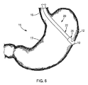
医療システム20及びその医療装置26を利用するための1つの適した方法を、図6から図13を参照してこれより説明していく。図6に示すように、食道16や胃17などの胃腸管15の上部は口(図示せず)を通してアクセスすることができる。内視鏡又は他の可視化装置の補助の有無にかかわらず、切断器を、胃壁又は胃組織12の開口部10を形成するために使用することができる。ワイヤーガイド、拡張器、および他の医療装置が、経管腔的処置を行うために開口部10を通して使用される。該方法のこれらの初期のステップを、参照目的及び背景状況を供与するために説明しており、本発明の医療システム20は身体内の任意の組織を内視鏡的に縫合するために使用できることが認識されるであろう。同様に、医療システム20は任意の自然開口部(例えば、口、肛門、膣、耳、鼻)並びに腹腔鏡処置又は類似の処置中に作られるものなどの意図的に形成された開口部を通して使用することができる。当業者によって認識されるように、体内管腔の組織によって画定される身体開口部10は、意図的に形成され又は自然に生じ得て、また、体内管腔は胃腸管の一部分又は任意の他の体内管腔を含むことができる。
One suitable method for utilizing the
図1と図6に示すように、医療装置26及びそのエンドキャップ42は、内視鏡22の遠位端に取り付けられている。医療システム20を開口部10に隣接した位置に導入し、図7に示すように、エンドキャップ42の遠位部を開口部10に通過させる。図8に示すように、医療システム20は、組織12が側面開口部48を通過して、内部空間46、特に中間の内部空間46i内に配置されるように操作される。内視鏡22の可視化要素23は内部空間46内で組織12の配置を可視化でき、内部空間46内に組織12がないときは、医療装置26の向こう側をエンドキャップ42の端部壁50を通して遠位方向に可視化できる。
As shown in FIGS. 1 and 6, the
図8に示すように、開口部10に隣接する組織12の第1の部位に配置された医療システム20を使用して、針アセンブリ24及びその針30は、内視鏡22の作業チャンネル28を通し、次に穿刺穴56を通って、遠位の内部空間46dのアンカー押し出し部54の中へ遠位方向に進められる。特に、支持リブ52の近位エッジ58、並びに側壁44の露出部分は、針30がそこを通って進められるときに組織12を支持する。医療システム20の近位端では、遠位の内部空間46dのアンカー押し出し部54に組織アンカー34を配置するために、針アセンブリ24のスタイレット38を針30に対して動かすことができる。
As shown in FIG. 8, using a
次に、図10に示すように、針アセンブリ24を内視鏡22の作業チャンネル28を通して近位方向に取り出すことができ、それにより、組織12の遠位側に組織アンカー34を残して組織12から該針アセンブリを取り除くことができる。縫合糸36は組織12を通過し、該縫合糸の一方の端部は作業チャンネル28、及び/又は、結合用の針30を通って追加の組織アンカー34及び医療システム20の近位端まで続いている。縫合糸36のもう一方の自由端は、側面開口部48を通り、医療システム20の外側に沿って体外の位置まで通り抜けており、それによって、縫合糸36の両端を医療専門家が操作することができる。
Next, as shown in FIG. 10, the
医療装置26及びエンドキャップ42の構造により、組織アンカー34は遠位の内部空間46dのアンカー押し出し部54を通って図10に示す長手方向の向きに移動することができる。同様に、穿刺穴56及び側面開口部48は、そこを通して組織アンカー34が直接通過するのを可能にしており、それにより、医療システム20を組織12の開口部10の周辺に沿って、開口部10に隣接する第2の部位まで摺動させることができる。医療システムが動かされると、組織アンカー34は、側面開口部48を通して簡単に医療装置26を出て、配備された第1の部位に残ることになる。医療システム20は開口部10の周辺に沿って摺動する必要はなく、組織12から横方向に離れて、該組織が内部空間46を出て、その後第2の部位が、さらなる組織アンカー34の配備のために特定され、標的とされ得るように動かすこともできる。
The structure of the
図11に示すように、複数の組織アンカー34が組織12の開口部10の周辺付近に配備され、縫合糸36の大部分が組織12の近位側に残る。複数の組織アンカー34は、概ね円形形態などで開口部10の周りに配備することができるが、ジグザグ形態など任意の数及び任意の構成のアンカー配備も使用することができる。縫合糸36の自由端36a、36bの両方が、開口部10を閉合するため、医療専門家により個別に操作するために体内管腔及び外口を通って近位方向に延在する。図13に示すように、特に端部36a、36bは、各組織アンカー34の間の距離を縮めるように張力をかけ、巾着縫合式に開口部10を閉合するために、開口部10の周りの組織12を圧縮することができる。縫合ロック60は、縫合糸36の端部36a、36bを一体に結合して、張力を維持するために使用することができ、また、縫合糸36は、当業者によって容易に理解されるように、結び目又は他の方法若しくは装置を使用することで結合することができる。幾つかの典型的な縫合ロックが2008年5月22日出願の米国特許出願第12/125、525号、及び2008年8月13日出願の米国特許出願第12/191、001号に開示されており、その開示全体を参照として本明細書に援用する。
As shown in FIG. 11, a plurality of tissue anchors 34 are deployed near the periphery of the
概括的に前述した方法が、体内管腔を通して組織装置を組織に配置するステップを含んでいることが当業者に認識され、当該システム、装置、および方法が、人又は動物の体及び体内管腔に関係する又は関係しないあらゆる材料層(例えば、織物、布、重合体、エラストマー、プラスチック、及びゴム)に使用できることが認識されるであろう。例えば、該システム、装置、および方法は、人又は動物の体への適用を見出すことができる、又は見出すことができない1つ以上の材料層を通して装置を配置するために、及び同様に身体組織でない材料層の穴又は穿孔を閉合するために、実験室と工業環境で使用することができる。 It will be appreciated by those skilled in the art that the method generally described above includes placing a tissue device into tissue through a body lumen, and the system, device, and method can be applied to a human or animal body and body lumen. It will be appreciated that any layer of material related to or not related to (e.g. fabrics, fabrics, polymers, elastomers, plastics and rubbers) can be used. For example, the system, device, and method are for positioning the device through one or more material layers that may or may not be found to be applied to the human or animal body, and likewise not body tissue Can be used in laboratory and industrial environments to close holes or perforations in material layers.
以上、本発明の様々な実施形態について、例示と説明を目的に述べてきた。それにより、本発明を余すところなく説明する意図も、開示されている厳密な実施形態に限定する意図もない。上記教示の観点から、数多くの修正又は変型が可能である。考察されている実施形態は、本発明の原理及びその実際の適用を最適に例示し、それにより、当業者が、考えられる特定の使用に適応させた様々な修正を施して利用することができるように、本発明を様々な実施形態で選択し記載した。全てのその様な修正及び変型は、付随の特許請求の範囲の請求項によって、それら請求項が公平、法的、且つ公正に権利を有するとされる一定の許容幅によって解釈された上に定まる本発明の範囲に含まれる。 The various embodiments of the present invention have been described above for purposes of illustration and description. It is thereby not intended to be exhaustive or to limit the invention to the precise embodiments disclosed. Many modifications or variations are possible in light of the above teaching. The discussed embodiments optimally illustrate the principles of the invention and its practical application so that those skilled in the art can make use of various modifications adapted to the particular use envisaged. Thus, the present invention has been selected and described in various embodiments. All such modifications and variations are determined by the appended claims, after being construed with a certain tolerance to which they are entitled fairly, legally and fairly. It is included in the scope of the present invention.
10 穿孔
10 開口部
12 組織
14、37 軸線
20 医療システム
22 内視鏡
23 可視化要素
24 針アセンブリ
26 医療装置
28 作業チャンネル
30 針
32 針のルーメン
34 組織アンカー
36 縫合糸
36a、36b 自由端
40 針のシース
42 鋭い遠位先端
42 エンドキャップ
44 側壁
44 環状の側壁
46d 遠位の内部空間
46i 中間の内部空間
46p 近位部分、近位の内部空間
46 内部空間
48 側面開口部
50 端部壁
52 支持リブ
52a 第1の位置
52b 第2の位置
54 アンカー押し出し部
56 穿刺穴
58 エッジ
60 縫合ロック
ASP 第2の円弧
ASR 第1の円弧
D1 最大径
D2 最小径
LA 長さ
DESCRIPTION OF
Claims (13)
内部空間を画定する環状の側壁によって画定された管形状を有するエンドキャップと、
前記環状の側壁によって画定される側面開口部であって、前記内部空間と連通し、前記内部空間内に前記組織を収容し配置できるサイズとされた側面開口部と、
前記内部空間内で前記側面開口部より遠位に配置された支持リブであって、前記側壁の第1の位置から前記側壁の第2の位置まで横方向に延在し且つ前記側面開口部から前記長手方向に延在し前記側面開口部より遠位にある、前記内部空間の一部を二分している支持リブと、を備え、
前記支持リブと前記側壁はその間に穿刺穴を画定し、前記穿刺穴は前記組織アンカーの長さより大きい最大径を有し、前記支持リブの近位エッジが縫合の間、前記内部空間の前記組織を支持するように位置した支持面を画定している、医療装置。 A medical device for use with an endoscope defining a longitudinal axis for suturing a tissue opening using a tissue anchor, comprising:
An end cap having a tubular shape defined by an annular side wall defining an interior space;
A side opening defined by the annular side wall, the side opening being in communication with the interior space and sized to receive and place the tissue in the interior space;
A support rib disposed distal to the side opening in the internal space, extending laterally from a first position of the side wall to a second position of the side wall and from the side opening A support rib that extends in the longitudinal direction and is distal to the side opening and bisects a portion of the interior space ;
The support rib and the side wall define a puncture hole therebetween, the puncture hole having a maximum diameter greater than the length of the tissue anchor, and the proximal edge of the support rib during the suturing while the tissue in the internal space A medical device defining a support surface positioned to support the device.
作業チャンネルを有し、長手方向の軸線を画定する内視鏡と、
遠位端及び針のルーメンを画定する針、前記針のルーメン内に摺動可能に収容される組織アンカー、並びに前記組織アンカーに取り付けられた縫合糸を有し、前記内視鏡の前記作業チャネル内に摺動可能に収容されている針アセンブリと、をさらに備えており、
前記内部空間は近位の内部空間と、中間の内部空間と、遠位の内部空間とを有し、前記近位の内部空間は前記内視鏡の遠位端を収容するサイズであり、前記側面開口部は前記中間の内部空間と連通し、前記支持リブは前記遠位の内部空間を二分して前記遠位の内部空間のアンカー押し出し部を画定している、医療システム。 A medical system comprising the medical device according to claim 1,
An endoscope having a working channel and defining a longitudinal axis;
The working channel of the endoscope having a needle defining a distal end and a needle lumen, a tissue anchor slidably received within the needle lumen, and a suture attached to the tissue anchor A needle assembly slidably received within the needle assembly,
Said inner space is proximal inner space of having an intermediate internal space, and a distal inner space, the inner space of the proximal is sized to accommodate the distal end of the endoscope, the A medical system, wherein a side opening communicates with the intermediate interior space, and the support rib bisects the distal interior space to define an anchor extrusion of the distal interior space.
Applications Claiming Priority (3)
| Application Number | Priority Date | Filing Date | Title |
|---|---|---|---|
| US10933708P | 2008-10-29 | 2008-10-29 | |
| US61/109,337 | 2008-10-29 | ||
| PCT/US2009/062057 WO2010051250A1 (en) | 2008-10-29 | 2009-10-26 | Endoscope endcap for suturing tissue |
Publications (3)
| Publication Number | Publication Date |
|---|---|
| JP2012507360A JP2012507360A (en) | 2012-03-29 |
| JP2012507360A5 JP2012507360A5 (en) | 2012-11-22 |
| JP5485286B2 true JP5485286B2 (en) | 2014-05-07 |
Family
ID=41416227
Family Applications (1)
| Application Number | Title | Priority Date | Filing Date |
|---|---|---|---|
| JP2011534660A Active JP5485286B2 (en) | 2008-10-29 | 2009-10-26 | Endoscopic end cap for suturing tissue |
Country Status (6)
| Country | Link |
|---|---|
| US (1) | US8376932B2 (en) |
| EP (1) | EP2348950B1 (en) |
| JP (1) | JP5485286B2 (en) |
| AU (1) | AU2009308996B2 (en) |
| CA (1) | CA2741530C (en) |
| WO (1) | WO2010051250A1 (en) |
Families Citing this family (11)
| Publication number | Priority date | Publication date | Assignee | Title |
|---|---|---|---|---|
| US8317679B2 (en) * | 2008-10-06 | 2012-11-27 | Cook Medical Technologies Llc | Endcap for safely deploying tissue anchors |
| JP5587981B2 (en) * | 2009-05-01 | 2014-09-10 | クック メディカル テクノロジーズ エルエルシー | Medical system, device and method for suturing perforations |
| US8894667B2 (en) | 2010-03-09 | 2014-11-25 | University Of Louisville Research Foundation, Inc. | Endoscopic closure device |
| US8771173B2 (en) * | 2010-12-14 | 2014-07-08 | Saint Joseph's Translational Research Institute, Inc. | Access device for surgery |
| CN203468565U (en) * | 2011-03-10 | 2014-03-12 | 松下电器产业株式会社 | Endoscopic camera and endoscopic device |
| US20130023904A1 (en) * | 2011-07-20 | 2013-01-24 | Yoshinori Morita | Suturing method |
| CN110623696A (en) | 2014-06-15 | 2019-12-31 | 安奇拉医疗有限公司 | Apparatus and method for suturing tissue |
| US9861356B2 (en) | 2014-10-01 | 2018-01-09 | Brainchild Surgical Devices Llc | Suturing device and method |
| US20170046507A1 (en) * | 2015-08-10 | 2017-02-16 | International Business Machines Corporation | Continuous facial recognition for adaptive data restriction |
| DE102016208624B4 (en) * | 2016-05-19 | 2018-02-15 | Universität Ulm | Apparatus for modifying an endoscope, modified endoscope and its use in gastrointestinal endoscopy and a method for suturing a wound |
| WO2018087769A1 (en) | 2016-11-13 | 2018-05-17 | Anchora Medical Ltd. | Minimally-invasive tissue suturing device |
Family Cites Families (29)
| Publication number | Priority date | Publication date | Assignee | Title |
|---|---|---|---|---|
| US5059201A (en) * | 1989-11-03 | 1991-10-22 | Asnis Stanley E | Suture threading, stitching and wrapping device for use in open and closed surgical procedures |
| GB9405790D0 (en) * | 1994-03-23 | 1994-05-11 | Univ London | Sewing device |
| US7744613B2 (en) * | 1999-06-25 | 2010-06-29 | Usgi Medical, Inc. | Apparatus and methods for forming and securing gastrointestinal tissue folds |
| US6358197B1 (en) * | 1999-08-13 | 2002-03-19 | Enteric Medical Technologies, Inc. | Apparatus for forming implants in gastrointestinal tract and kit for use therewith |
| US6719763B2 (en) * | 2000-09-29 | 2004-04-13 | Olympus Optical Co., Ltd. | Endoscopic suturing device |
| US6997931B2 (en) * | 2001-02-02 | 2006-02-14 | Lsi Solutions, Inc. | System for endoscopic suturing |
| US8142448B2 (en) * | 2001-11-26 | 2012-03-27 | Olympus Corporation | Endoscopic instruments for suturing tissues in a body cavity |
| US20030225312A1 (en) * | 2002-03-18 | 2003-12-04 | Anthony Kalloo | Endoscopic system for treating inside of body cavity |
| US8105342B2 (en) * | 2002-05-08 | 2012-01-31 | Apollo Endosurgery, Inc. | Apparatus for ligating/suturing living tissues and system for resecting/suturing living tissues |
| JP4373146B2 (en) * | 2002-07-11 | 2009-11-25 | オリンパス株式会社 | Endoscopic suturing device |
| US20040158125A1 (en) * | 2002-09-06 | 2004-08-12 | Aznoian Harold M. | Integrated endoscope and accessory treatment device |
| US6908427B2 (en) * | 2002-12-30 | 2005-06-21 | PARÉ Surgical, Inc. | Flexible endoscope capsule |
| WO2004069056A1 (en) * | 2003-02-04 | 2004-08-19 | Kiyoshi Hashiba | Endoscopic suturing apparatus |
| CN1822794B (en) * | 2003-05-16 | 2010-05-26 | C.R.巴德有限公司 | Single intubation, multi-stitch endoscopic suturing system |
| US7431694B2 (en) * | 2003-05-16 | 2008-10-07 | Ethicon Endo-Surgery, Inc. | Method of guiding medical devices |
| US7815565B2 (en) * | 2003-05-16 | 2010-10-19 | Ethicon Endo-Surgery, Inc. | Endcap for use with an endoscope |
| JP4217587B2 (en) * | 2003-11-26 | 2009-02-04 | オリンパス株式会社 | Endoscope cap |
| WO2005065554A1 (en) * | 2004-01-08 | 2005-07-21 | Olympus Corporation | Anastomosis device and method of excising wall portion of in vivo luminal organ |
| US7211093B2 (en) * | 2004-01-14 | 2007-05-01 | Lsi Solutions, Inc. | Sew-right running stitch instrument |
| JP4700384B2 (en) * | 2004-04-07 | 2011-06-15 | オリンパス株式会社 | Medical ligature suturing apparatus and medical ligature suturing system |
| JP4643328B2 (en) * | 2004-04-07 | 2011-03-02 | オリンパス株式会社 | Medical ligature suturing device |
| US8172857B2 (en) * | 2004-08-27 | 2012-05-08 | Davol, Inc. | Endoscopic tissue apposition device and method of use |
| JP4302602B2 (en) * | 2004-09-24 | 2009-07-29 | オリンパス株式会社 | Endoscopic treatment tool, endoscopic treatment system, and support adapter |
| US7645286B2 (en) * | 2005-05-20 | 2010-01-12 | Neotract, Inc. | Devices, systems and methods for retracting, lifting, compressing, supporting or repositioning tissues or anatomical structures |
| US7731727B2 (en) * | 2006-04-26 | 2010-06-08 | Lsi Solutions, Inc. | Medical instrument to place a pursestring suture, open a hole and pass a guidewire |
| US20080097152A1 (en) * | 2006-07-20 | 2008-04-24 | David Stefanchik | Braided endoscope accessories |
| US8088062B2 (en) * | 2007-06-28 | 2012-01-03 | Ethicon Endo-Surgery, Inc. | Interchangeable endoscopic end effectors |
| US8888792B2 (en) * | 2008-07-14 | 2014-11-18 | Ethicon Endo-Surgery, Inc. | Tissue apposition clip application devices and methods |
| US8241204B2 (en) * | 2008-08-29 | 2012-08-14 | Ethicon Endo-Surgery, Inc. | Articulating end cap |
-
2009
- 2009-10-26 CA CA2741530A patent/CA2741530C/en active Active
- 2009-10-26 JP JP2011534660A patent/JP5485286B2/en active Active
- 2009-10-26 WO PCT/US2009/062057 patent/WO2010051250A1/en active Application Filing
- 2009-10-26 AU AU2009308996A patent/AU2009308996B2/en active Active
- 2009-10-26 US US12/605,763 patent/US8376932B2/en active Active
- 2009-10-26 EP EP09745205.6A patent/EP2348950B1/en active Active
Also Published As
| Publication number | Publication date |
|---|---|
| CA2741530C (en) | 2017-01-24 |
| CA2741530A1 (en) | 2010-05-06 |
| EP2348950A1 (en) | 2011-08-03 |
| AU2009308996B2 (en) | 2013-05-09 |
| JP2012507360A (en) | 2012-03-29 |
| AU2009308996A1 (en) | 2010-05-06 |
| EP2348950B1 (en) | 2015-03-18 |
| WO2010051250A1 (en) | 2010-05-06 |
| US8376932B2 (en) | 2013-02-19 |
| US20100121140A1 (en) | 2010-05-13 |
Similar Documents
| Publication | Publication Date | Title |
|---|---|---|
| JP5485286B2 (en) | Endoscopic end cap for suturing tissue | |
| AU2009204417B2 (en) | Medical systems and devices for endoscopically suturing perforations | |
| US8939897B2 (en) | Methods for closing a gastrotomy | |
| JP5539897B2 (en) | Device for delivering an anchor device into the wall of a body passage | |
| US6988987B2 (en) | Guide tube | |
| US8480657B2 (en) | Detachable distal overtube section and methods for forming a sealable opening in the wall of an organ | |
| US7967842B2 (en) | Integrated securement and closure apparatus | |
| JP5894930B2 (en) | Medical instrument and method for suturing tissue | |
| US8317679B2 (en) | Endcap for safely deploying tissue anchors | |
| WO2011047229A1 (en) | Otomy closure device | |
| US20130324795A1 (en) | Three-dimensional retractor | |
| EP1507481B1 (en) | A device for transfixing and joining tissue | |
| US20070156165A1 (en) | Percutaneous transgastric gastroplication and transgastric minimally invasive surgery | |
| US8152835B2 (en) | Methods for the placement of sutures in tissue | |
| Kanehira et al. | Wedge gastric and Endo-gastric resection |
Legal Events
| Date | Code | Title | Description |
|---|---|---|---|
| A711 | Notification of change in applicant |
Free format text: JAPANESE INTERMEDIATE CODE: A711 Effective date: 20120206 |
|
| A521 | Request for written amendment filed |
Free format text: JAPANESE INTERMEDIATE CODE: A523 Effective date: 20121005 |
|
| A621 | Written request for application examination |
Free format text: JAPANESE INTERMEDIATE CODE: A621 Effective date: 20121005 |
|
| A977 | Report on retrieval |
Free format text: JAPANESE INTERMEDIATE CODE: A971007 Effective date: 20130925 |
|
| A131 | Notification of reasons for refusal |
Free format text: JAPANESE INTERMEDIATE CODE: A131 Effective date: 20131001 |
|
| A521 | Request for written amendment filed |
Free format text: JAPANESE INTERMEDIATE CODE: A523 Effective date: 20140106 |
|
| TRDD | Decision of grant or rejection written | ||
| A01 | Written decision to grant a patent or to grant a registration (utility model) |
Free format text: JAPANESE INTERMEDIATE CODE: A01 Effective date: 20140128 |
|
| A61 | First payment of annual fees (during grant procedure) |
Free format text: JAPANESE INTERMEDIATE CODE: A61 Effective date: 20140219 |
|
| R150 | Certificate of patent or registration of utility model |
Ref document number: 5485286 Country of ref document: JP Free format text: JAPANESE INTERMEDIATE CODE: R150 |
|
| R250 | Receipt of annual fees |
Free format text: JAPANESE INTERMEDIATE CODE: R250 |
|
| R250 | Receipt of annual fees |
Free format text: JAPANESE INTERMEDIATE CODE: R250 |
|
| R250 | Receipt of annual fees |
Free format text: JAPANESE INTERMEDIATE CODE: R250 |
|
| R250 | Receipt of annual fees |
Free format text: JAPANESE INTERMEDIATE CODE: R250 |
|
| R250 | Receipt of annual fees |
Free format text: JAPANESE INTERMEDIATE CODE: R250 |
|
| R250 | Receipt of annual fees |
Free format text: JAPANESE INTERMEDIATE CODE: R250 |
|
| R250 | Receipt of annual fees |
Free format text: JAPANESE INTERMEDIATE CODE: R250 |
|
| R250 | Receipt of annual fees |
Free format text: JAPANESE INTERMEDIATE CODE: R250 |