JP5485006B2 - Turbine airflow rectifier - Google Patents
Turbine airflow rectifier Download PDFInfo
- Publication number
- JP5485006B2 JP5485006B2 JP2010104701A JP2010104701A JP5485006B2 JP 5485006 B2 JP5485006 B2 JP 5485006B2 JP 2010104701 A JP2010104701 A JP 2010104701A JP 2010104701 A JP2010104701 A JP 2010104701A JP 5485006 B2 JP5485006 B2 JP 5485006B2
- Authority
- JP
- Japan
- Prior art keywords
- air
- perforated
- longitudinal axis
- wall
- fuel
- Prior art date
- Legal status (The legal status is an assumption and is not a legal conclusion. Google has not performed a legal analysis and makes no representation as to the accuracy of the status listed.)
- Expired - Fee Related
Links
Images


Classifications
-
- F—MECHANICAL ENGINEERING; LIGHTING; HEATING; WEAPONS; BLASTING
- F23—COMBUSTION APPARATUS; COMBUSTION PROCESSES
- F23R—GENERATING COMBUSTION PRODUCTS OF HIGH PRESSURE OR HIGH VELOCITY, e.g. GAS-TURBINE COMBUSTION CHAMBERS
- F23R3/00—Continuous combustion chambers using liquid or gaseous fuel
- F23R3/02—Continuous combustion chambers using liquid or gaseous fuel characterised by the air-flow or gas-flow configuration
- F23R3/04—Air inlet arrangements
-
- F—MECHANICAL ENGINEERING; LIGHTING; HEATING; WEAPONS; BLASTING
- F23—COMBUSTION APPARATUS; COMBUSTION PROCESSES
- F23M—CASINGS, LININGS, WALLS OR DOORS SPECIALLY ADAPTED FOR COMBUSTION CHAMBERS, e.g. FIREBRIDGES; DEVICES FOR DEFLECTING AIR, FLAMES OR COMBUSTION PRODUCTS IN COMBUSTION CHAMBERS; SAFETY ARRANGEMENTS SPECIALLY ADAPTED FOR COMBUSTION APPARATUS; DETAILS OF COMBUSTION CHAMBERS, NOT OTHERWISE PROVIDED FOR
- F23M9/00—Baffles or deflectors for air or combustion products; Flame shields
- F23M9/02—Baffles or deflectors for air or combustion products; Flame shields in air inlets
Landscapes
- Engineering & Computer Science (AREA)
- Chemical & Material Sciences (AREA)
- Combustion & Propulsion (AREA)
- Mechanical Engineering (AREA)
- General Engineering & Computer Science (AREA)
- Jet Pumps And Other Pumps (AREA)
- Nozzles (AREA)
Description
本発明は広義にはタービンエンジンに関し、具体的には、空気室内の空気分布を改善する空気流整流システムに関する。 The present invention relates generally to turbine engines and, more particularly, to an air flow rectification system that improves air distribution within an air chamber.
タービンエンジンなどの様々なエンジンにおいて、燃料と空気の混合はエンジン性能及び排出量に影響する。例えば、ガスタービンエンジンには、燃焼器内での燃料空気混合を促進するため1以上の燃料ノズルを用いて空気及び燃料を取り入れるものがある。ノズルをタービンのヘッドエンド部に配置し、空気流を取り入れて燃料入力と混合するように構成することがある。しかし、空気流が複数のノズル間で一様に分配されないことがあり、燃料と空気の混合にばらつきを生じる。さらに、単一ノズルの実施形態では、タービン燃焼器のヘッドエンドの幾何形状のため、空気流がノズル内で一様でなくなることがある。燃料ノズル内での不均一な流れは燃料との不適当な混合を招いて、タービンエンジンの性能及び効率を低下させてしまう。その結果、ヘッドエンドに入る空気流は、各ノズル内への及び複数のノズル間での空気の不均一な流れのため、排出量の増大及び性能の低下を起こすおそれがある。 In various engines, such as turbine engines, fuel and air mixing affects engine performance and emissions. For example, some gas turbine engines incorporate air and fuel using one or more fuel nozzles to promote fuel-air mixing within the combustor. A nozzle may be located at the head end of the turbine and configured to take an air flow and mix with the fuel input. However, the air flow may not be evenly distributed among the plurality of nozzles, resulting in variations in the mixing of fuel and air. Further, in a single nozzle embodiment, the air flow may not be uniform within the nozzle due to the geometry of the turbine combustor head end. Non-uniform flow within the fuel nozzle leads to inadequate mixing with the fuel, reducing the performance and efficiency of the turbine engine. As a result, the air flow entering the head end can cause increased emissions and reduced performance due to the non-uniform flow of air into each nozzle and between multiple nozzles.
本願出願当初の特許請求の範囲に記載された発明の幾つかの実施形態について要約する。これらの実施形態は、特許請求の範囲に記載された発明の技術的範囲を限定するものではなく、本発明の可能な形態を簡単にまとめたものである。実際、本発明は、以下に記載する実施形態と同様のものだけでなく、異なる様々な実施形態を包含する。 Several embodiments of the invention described in the scope of claims of the present application will be summarized. These embodiments do not limit the technical scope of the invention described in the claims, but simply summarize possible forms of the invention. Indeed, the invention is not limited to the embodiments set forth below but encompasses various different embodiments.
第1の実施形態では、システムはタービンエンジンを備える。タービンエンジンは燃焼器を備える。燃焼器は燃焼室を備える。燃焼器は空気室も備える。燃焼器はさらに、燃焼室と空気室の間に仕切板を備える。さらに、燃焼器は、仕切板を通って延在する燃料ノズルを備える。燃料ノズルは、空気室内の空気入口と燃焼室内の出口とを有する有する。燃焼器は、空気室への空気供給経路に沿って空気室に設けられた空気流整流器も備える。空気流整流器は、空気供給経路からの空気流を、空気室の中央部に向けて内側に転向させるように構成された有孔転向羽根を備える。 In a first embodiment, the system comprises a turbine engine. The turbine engine includes a combustor. The combustor includes a combustion chamber. The combustor also includes an air chamber. The combustor further includes a partition plate between the combustion chamber and the air chamber. Further, the combustor includes a fuel nozzle that extends through the partition plate. The fuel nozzle has an air inlet in the air chamber and an outlet in the combustion chamber. The combustor also includes an air flow rectifier provided in the air chamber along an air supply path to the air chamber. The air flow rectifier includes a perforated turning vane configured to turn the air flow from the air supply path inward toward the center of the air chamber.
第2の実施形態では、システムは、タービン燃焼器の燃焼室から隔てられた空気室に装着されるように構成された空気流整流器を備える。空気流整流器は、タービン燃焼器の軸に対して軸方向及び半径方向に空気流を向けるように構成された有孔環状壁を備える。さらに、空気流整流器は、1以上の燃料ノズルの空気入口に空気流を均一に供給するように構成されている。 In a second embodiment, the system comprises an airflow rectifier configured to be mounted in an air chamber separated from a combustion chamber of a turbine combustor. The airflow rectifier comprises a perforated annular wall configured to direct the airflow axially and radially with respect to the turbine combustor axis. Further, the airflow rectifier is configured to uniformly supply an airflow to the air inlet of one or more fuel nozzles.
第3の実施形態では、システムはタービン燃焼器を備える。タービン燃焼器は燃焼室を備える。タービン燃焼器は、燃焼生成物の流れに対して燃焼室の上流にヘッドエンドも備える。ヘッドエンドは、ヘッドエンドに設けられた燃料ノズルを備える。燃料ノズルは、タービン燃焼器の長手軸に対して第1の軸方向位置に空気入口を備える。ヘッドエンドは、ヘッドエンドに設けられた空気流整流器も備える。空気流整流器は、長手軸に対して第2の軸方向位置に配置される。第1の軸方向位置は第2の軸方向位置とは異なる。 In a third embodiment, the system comprises a turbine combustor. The turbine combustor includes a combustion chamber. The turbine combustor also includes a head end upstream of the combustion chamber for the flow of combustion products. The head end includes a fuel nozzle provided at the head end. The fuel nozzle includes an air inlet at a first axial position relative to the longitudinal axis of the turbine combustor. The head end also includes an air flow rectifier provided at the head end. The airflow rectifier is disposed at a second axial position relative to the longitudinal axis. The first axial position is different from the second axial position.
本発明の上記その他の特徴、態様及び利点については、図面と併せて以下の詳細な説明を参照することによって理解を深めることができるであろう。図面を通して、同様の部材には同様の符号を付した。 These and other features, aspects and advantages of the present invention may be better understood by reference to the following detailed description taken in conjunction with the drawings in which: Throughout the drawings, like reference numerals are used for like members.
以下、本発明の1以上の特定の実施形態について説明する。これらの実施形態を簡潔に説明するため、現実の実施に際してのあらゆる特徴について本明細書に記載しないこともある。実施化に向けての開発に際して、あらゆるエンジニアリング又は設計プロジェクトの場合と同様に、実施毎に異なる開発者の特定の目標(システム及び業務に関連した制約に従うことなど)を達成すべく、実施に特有の多くの決定を行う必要があることは明らかであろう。さらに、かかる開発努力は複雑で時間を要することもあるが、本明細書の開示内容に接した当業者にとっては日常的な設計、組立及び製造にすぎないことも明らかである。 The following describes one or more specific embodiments of the present invention. In an effort to provide a concise description of these embodiments, all features in an actual implementation may not be described herein. As with any engineering or design project, when developing for implementation, implementation-specific to achieve specific developer goals (such as complying with system and operational constraints) that vary from implementation to implementation It will be clear that many decisions need to be made. Furthermore, while such development efforts may be complex and time consuming, it will be apparent to those of ordinary skill in the art who have access to the disclosure herein only routine design, assembly and manufacture.
本発明の様々な実施形態の構成要素について紹介する際、単数形で記載したものは、その構成要素が1以上存在することを意味する。「含む」、「備える」及び「有する」という用語は内包的なものであり、記載した構成要素以外の追加の要素が存在していてもよいことを意味する。作動パラメータ及び/又は環境条件の例は、開示した実施形態以外のパラメータ/条件を除外するものではない。さらに、本発明の「一実施形態」又は「実施形態」という場合、その実施形態に記載された特徴をもつ別の実施形態が存在することを除外するものではない。 When introducing components of various embodiments of the present invention, what is written in the singular means that there are one or more of the components. The terms “comprising”, “comprising” and “having” are inclusive and mean that there may be additional elements other than the listed components. Examples of operating parameters and / or environmental conditions do not exclude parameters / conditions other than the disclosed embodiments. Furthermore, references to “one embodiment” or “an embodiment” of the present invention do not exclude the presence of other embodiments having the features described in that embodiment.
以下で詳しく説明する通り、、タービンエンジンの性能を向上させ、排出量を低減するため、空気流整流器及び関連構造の様々な実施形態を用いることができる。例えば、開示した空気流整流器をガスタービン燃焼器のヘッドエンド領域に配置すれば、空気流整流器によって1以上の燃料ノズルへの空気流の分布及び均一性を改善することができる。空気流整流器は、複数の燃料ノズル間(2以上の燃料ノズルが存在する場合)での空気流の均一性を改善するとともに、各燃料ノズル(例えば、各燃料ノズルの周囲の空気流整流器)に入る空気流の均一性も改善するように構成される。 As described in detail below, various embodiments of airflow rectifiers and related structures can be used to improve turbine engine performance and reduce emissions. For example, if the disclosed airflow rectifier is placed in the head end region of a gas turbine combustor, the airflow rectifier can improve the distribution and uniformity of the airflow to one or more fuel nozzles. The air flow rectifier improves the uniformity of the air flow between multiple fuel nozzles (when there are two or more fuel nozzles) and at each fuel nozzle (eg, the air flow rectifier around each fuel nozzle). It is configured to improve the uniformity of the incoming air flow.
例えば、空気流整流器の実施形態は有孔転向羽根を含んでいてもよく、有孔転向羽根は、燃焼器の長手軸に沿って直径が変化する環状構造体である。具体的には、有孔転向羽根は凸状でも凹状でもよく、有孔転向羽根は、燃焼器の長手軸に沿って空気流を軸方向及び半径方向内側及び外側に向けるように構成される。半径方向及び軸方向を含めた複数の方向に空気を向けることによって、有孔転向羽根は、大規模な流動構造を小さな流動構造へと分解し、もって燃焼器のヘッドエンドの空気室内で均衡した空気質量流を生じるように構成される。 For example, airflow rectifier embodiments may include perforated turning vanes, which are annular structures that vary in diameter along the longitudinal axis of the combustor. Specifically, the perforated turning vanes may be convex or concave, and the perforated turning vanes are configured to direct the air flow axially and radially inward and outward along the longitudinal axis of the combustor. By directing air in multiple directions including radial and axial directions, the perforated turning vane breaks up the large flow structure into a small flow structure, thus balancing in the air chamber at the combustor head end Configured to produce an air mass flow.
別の実施形態では、有孔転向羽根は円錐形でも環状の幾何形状でもよく、空気流を空気室内で軸方向及び半径方向に向けるように構成してもよい。さらに、有孔転向羽根は有孔円筒又は壁に連結してもよく、有孔円筒又は壁は空気を半径方向に向けるように構成された環状構造であってもよい。有孔環状壁又は円筒を、有孔転向羽根と共に用いると、空気室内の流動構造を壊して、空気室内の1以上の燃料ノズルに一様に均衡して空気を分配することができる。 In another embodiment, the perforated turning vane may be conical or annular geometry and may be configured to direct the air flow axially and radially within the air chamber. Further, the perforated turning vane may be connected to a perforated cylinder or wall, and the perforated cylinder or wall may be an annular structure configured to direct air radially. When a perforated annular wall or cylinder is used with a perforated turning vane, the flow structure in the air chamber can be broken to evenly distribute the air to one or more fuel nozzles in the air chamber.
したがって、1以上の燃料ノズルへの空気の改善・均衡した流れによって、燃焼器内での空気と燃料の混合の予測性を高めることができ、性能が改善される。さらに、有孔転向羽根環状部材を含む有孔空気流整流器は、燃料ノズルに入る空気流を均一化して個々の燃料ノズルへの流れを改善できる。有孔転向羽根環状部材を含む有孔空気流整流器は、ヘッドエンドの空気室に分配される空気を均一化し均衡させることができ、複数の燃料ノズル間での吸気量の一様な分布が確保される。こうして、燃料ノズル間での空気の均一な分布によって燃焼性能が向上し、もって排出量が低減するとともにシステム効率が向上する。 Thus, the improved and balanced flow of air to one or more fuel nozzles can increase the predictability of air and fuel mixing in the combustor and improve performance. In addition, a perforated airflow rectifier that includes a perforated turning vane annular member can improve the flow to individual fuel nozzles by equalizing the airflow entering the fuel nozzles. A perforated airflow rectifier that includes a perforated turning vane annular member can equalize and balance the air distributed to the air chamber at the head end, ensuring a uniform distribution of intake air among multiple fuel nozzles Is done. Thus, the uniform distribution of air between the fuel nozzles improves combustion performance, thereby reducing emissions and improving system efficiency.
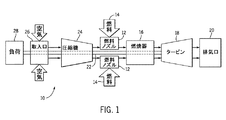
次いで図面のうち、まず図1を参照すると、タービンシステム10の実施形態のブロック図が示してある。以下で詳しく説明する通り、開示したタービンシステム10では、空気流整流器を用いて、タービンシステム10の性能を改善するとともに排出量を低減することができる。タービンシステム10は、液体又はガス燃料(例えば天然ガス及び/又は水素リッチ合成ガス)を用いて、タービンシステム10を運転し得る。図に示すように、複数の燃料ノズル12で、燃料供給14を取り込んで燃料と空気を混合し、空気燃料混合気を燃焼器16に分配する。空気燃料混合気は燃焼器16内の燃焼室で燃焼して、高温加圧排気ガスを生成する。燃焼器16は排気ガスをタービン18を通して排気口20へと送る。排気ガスがタービン18を通過する際に、ガスが1以上のタービン動翼に作用して、システム10の軸に沿ってシャフト22を回転させる。図に示すように、シャフト22を、タービンシステム10の様々な構成要素(例えば、圧縮機24)に接続してもよい。圧縮機24も動翼を備えており、動翼はシャフト22に連結してもよい。シャフト22が回転すると圧縮機24内の動翼も回転し、その結果、空気取入口26からの空気が、圧縮機24を通る間に圧縮されて燃料ノズル12及び/又は燃焼器16に入る。シャフト22は、負荷28に接続していてもよい。負荷28は、車両でもよいし、定常負荷(例えば発電所における発電機又は航空機のプロペラなと)でもよい。当然のことながら、負荷28は、タービンシステム10の回転出力によってパワー供給することができる任意の好適な装置を含んでいてもよい。
Referring now to FIG. 1 of the drawings, a block diagram of an embodiment of a
図2に、図1に概略的に示したタービンシステム10の実施形態の側断面図を示す。タービンシステム10は、1以上の燃焼器16の内部に配置された1以上の燃料ノズル12を備える。動作時には、空気が、空気取入口26を通ってタービンシステム10に入る。空気を圧縮機24において加圧してもよい。圧縮空気を次に、燃焼器16内でガスと混合して燃焼を図ってもよい。例えば、燃料ノズル12から燃料空気混合気を燃焼器16内に、最適な燃焼、排出、燃料消費、及びパワー出力に適した比率で噴射してもよい。燃焼によって高温加圧排気ガスが発生する。高温加圧排気ガスによって次に、タービン18内の1以上の動翼30が駆動され、シャフト22したがって圧縮機24及び負荷28が回転する。タービン動翼30が回転することによってシャフト22が回転し、その結果、圧縮機24内の動翼32が、取入口26によって受け取られた空気を吸い込んで加圧する。
FIG. 2 illustrates a cross-sectional side view of an embodiment of the
以下で詳しく説明する通り、タービンシステム10の実施形態は、燃料ノズル12に入る空気の流れを改善するために、ある構造及び構成要素を燃焼器16のヘッドエンド内に備え、その結果、性能が改善されて排出が低下する。例えば、空気流整流器(有孔転向羽根を含む)を、空気室に至る空気流路に配置してもよい。有孔転向羽根によって、空気が、一様で均衡した方法で送られて、燃料ノズル12に入る空気の分布が改善され、その結果、燃料空気混合気比率が改善されて、その比率の精度が高まる。
As will be described in detail below, embodiments of the
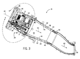
図3は、1以上の燃料ノズル12を有する燃焼器16の実施形態の側断面図である。燃料ノズル12は、ヘッドエンド領域34から圧縮空気を吸い込むように配置してもよい。端部カバー36が、燃料及び/又は加圧ガスを燃料ノズル12に送る導管又は経路を備えていてもよい。圧縮機24からの圧縮空気38が、燃焼器16に、燃焼器流れスリーブ42と燃焼器ライナ44との間に形成された環状通路40を通って流れ込む。圧縮空気38はヘッドエンド領域34に流れ込む。ヘッドエンド領域34には、複数の燃料ノズル12が含まれている。特に、ある実施形態では、ヘッドエンド領域34は、ヘッドエンド領域34の中央の長手軸46を通って延在する中央の燃料ノズル12と、中央の長手軸46の周りに配置された複数の外部燃料ノズル12とを備えていてもよい。しかし他の実施形態では、ヘッドエンド領域34は、中央の長手軸46を通って延在する1つの燃料ノズル12のみを備えていてもよい。ヘッドエンド領域34内の燃料ノズル12の特定の構成は、特定の設計間で変わってもよい。
FIG. 3 is a cross-sectional side view of an embodiment of a
しかし一般的に、ヘッドエンド領域34に流れ込む圧縮空気38は、燃料ノズル12に、吸気口穿孔48を有するノズル吸気流整流器を通って流れ込んでもよい。吸気口穿孔48は燃料ノズル12の外部の円筒壁に配置してもよい。以下でより詳しく説明する通り、空気流整流器50があると、圧縮空気38がヘッドエンド領域34に送られたときに、圧縮空気38の大規模な流動構造(例えば、単一の環状噴流)を小さな流動構造へと壊すことがある。さらに、空気流整流器50は、空気流を、異なる燃料ノズル12間での空気流分布の均一性が高まる仕方で案内するか又は送る。その結果、各個々の燃料ノズル12に入る空気流の均一性も改善される。したがって、圧縮空気38の分配がより一様になって、ヘッドエンド領域34内の燃料ノズル12間で空気取り入れがバランスされることがある。圧縮空気38は燃料ノズル12に吸気口穿孔48を介して入った後に、燃料と混合して、燃焼器ライナ44の内部容積52を通って流れる(矢印54で示す)。空気及び燃料の混合物は燃焼キャビティ56に流れこむ。燃焼キャビティ56は燃焼ゾーンとして機能してもよい。燃焼キャビティ56から出た加熱された燃焼ガスが、タービンノズル58に流れ込み(矢印60で示す)、そこで燃焼ガスがタービン18に送出される。
In general, however, the
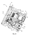
図4は、図3の線4−4で囲まれたヘッドエンド領域34の実施形態の側断面図である。図に示すように、圧縮空気38がヘッドエンド領域34に入ってもよく、方向を変えて燃料ノズル12の吸気口穿孔48に入ってもよい(矢印62で示す)。前述したように、燃料ノズル12内では、圧縮空気38を燃料及び/又は加圧ガス64と混合してもよい。燃料及び/又は加圧ガス64は、燃料ノズル12に、端部カバー36を通る導管及びバルブを通して導入される。空気/燃料混合気66を次に、ヘッドエンド領域34から燃焼器ライナ44の内部容積52(図3に示す)に送ってもよい。
4 is a cross-sectional side view of an embodiment of the
図4に示すように、燃料ノズル12に入る前に、ヘッドエンド領域34に流れ込む圧縮空気38は空気流整流器50を通ってもよい。空気流整流器50は、ヘッドエンド領域34内の空気室68に配置されている。空気室68は、空気流ダンプ領域又は空気流反転領域と記述してもよい。なぜならば、空気流が、より大きな体積の中に拡がるとともに、方向を上流流れ方向から下流流れ方向へと反転させるからである。前述したように、圧縮空気38が燃料ノズル12に入る均一性を高めることを確実にすることによって、空気流整流器50による燃焼器16の性能の改善が行なわれることがある。特に、空気流整流器50によって、燃料ノズル12間で圧縮空気38が均一に分配されるとともに、個々のノズル断面に渡って圧縮空気38が均一に分配される。言い換えれば、空気流整流器50は、燃料ノズル12の吸気口穿孔48の中に圧縮空気38の流れを均一に供給して、複数の燃料ノズル12間で圧縮空気38の流れを均一に分配するように、構成されている。具体的には、空気流整流器50は、圧縮空気38の流れを、ヘッドエンド領域34の中央の長手軸46に対して軸方向及び半径方向に向けるように構成されている。 図に示すように、空気流整流器50は、圧縮空気38流れを高めることに寄与する2つの主な特徴を備えていてもよい。特に、空気流整流器50は、圧縮空気38を空気室68の中央部に向かって転向させるように構成された有孔転向羽根70を備えていてもよい。具体的には、有孔転向羽根70は、圧縮空気38の方向を燃料ノズル12の吸気口穿孔48の方へゆるやかに変えてもよい。例えば、有孔転向羽根70のある実施形態は一般的に、空気流の方向を、1以上の角度の付いた構造又は湾曲形構造を用いて変える。これらの構造の角度は少なくとも、長手軸に対して0、10、20、30、40、50、60、70、又は80度より大きくてもよい。有孔転向羽根70は、ヘッドエンド領域34の中央の長手軸46の周りに配置された有孔環状壁72を備えていてもよい。有孔環状壁72は、中央の長手軸46に沿って直径が変わってもよい。例えば、図4に示すように、有孔環状壁72は、中央の長手軸46に沿って燃焼器端部74からヘッドエンド76へと直径が徐々に小さくなってもよい。ある実施形態では、有孔環状壁72は、中央の長手軸46に沿って直線的に収束又は発散する複数の円錐壁を備えていてもよい。例えば、図4に示すように、有孔環状壁72は、第1の有孔環状壁78と、第1の有孔環状壁78が接続される第2の有孔壁80とを備えていてもよい。図に示すように、第1の有孔環状壁78は中央の長手軸46に向かって徐々に収束しているだけであり、一方で、第2の有孔壁80は中央の長手軸46に向かってより急激に集束している。実際、以下でより詳しく説明する通り、有孔環状壁72は、燃料ノズル12に向かう圧縮空気38の流れを高めることがある様々な構成及び配置を備えていてもよい。
ある実施形態では、有孔環状壁72に加えて、空気流整流器50は、有孔円筒82を備えていてもよい。本質的に、有孔円筒82は、有孔環状壁72に接続しヘッドエンド領域34の燃焼器端部74に向かって後方に延在する空気流整流器50の内部有孔環状壁であってもよい。図4に示すように、有孔円筒82は、ヘッドエンド領域34の中央の長手軸46の周りに配置された有孔円筒壁を構成してもよい。有孔円筒82は、中央の長手軸46に沿って直径が略一定であってもよい。特に、ある実施形態では、有孔円筒82及び有孔環状壁72は互いに略同心であってもよい。一般的に、有孔円筒82は、圧縮空気38の方向を燃料ノズル12の方に最適な方法で変える際に、有孔環状壁72を補ってもよい。
As shown in FIG. 4, the
In some embodiments, in addition to the perforated
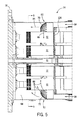
図5は、ヘッドエンド領域34の実施形態の別の側断面図である。前述したように、圧縮空気38はヘッドエンド領域34に入って空気流整流器50に渡って流れてもよい。図5に示すように、ある実施形態では、空気流整流器50は有孔転向羽根70のみを備えていてもよい。圧縮空気38が空気流整流器50に渡って流れるときに、圧縮空気38を、ヘッドエンド領域34の中央の長手軸46に対して軸方向84及び半径方向86の両方に送ってもよい。一般的に、軸方向84に送られた圧縮空気38は、ヘッドエンド領域34の半径方向の周囲に沿った燃料ノズル12に向かって集中し、一方で、半径方向86に送られた圧縮空気38は、中央の長手軸46の近くに配置された燃料ノズル12に向かってより分散される。こうして圧縮空気38が燃料ノズル12間でより一様に分配される場合があり、圧縮空気38がヘッドエンド領域34に入る近くで燃料ノズル12に向かって集中するのとは対照的である。例えば、矢印88は、ヘッドエンド領域34において複数の燃料ノズル12間でより一様に分配された圧縮空気38を例示している。ある実施形態では、有孔転向羽根70を燃料ノズル、整流器などの特定の配置に合わせて調整してもよい。例えば、有孔転向羽根70の調整を、有孔転向羽根70の角度、幾何形状、及び長さを調整する一方で穿孔の数、サイズ、及び分布も調整することによって行なってもよい。
FIG. 5 is another cross-sectional side view of an embodiment of the
図6は、図5の線分6−6に沿って見たヘッドエンド領域34の例示的実施形態の正面断面図であり、燃料ノズル12間で圧縮空気38の半径方向に均一な分布を示す。ヘッドエンド領域34は複数の燃料ノズル12を備えていてもよい。特に、ある実施形態では、ヘッドエンド領域34は、1つの中心に配置された燃料ノズル90と、中心に配置された燃料ノズル90の周りに半径方向に配置された複数の燃料ノズル92、94、96、98、及び100とを備えていてもよい。前述したように、空気流整流器50は、圧縮空気38が燃料ノズル90、92、94、96、98、及び100間で均一に分散されるとともに各個々の燃料ノズルの周りに均一に分散されるのを確実にするのに役立つことがある。例えば、中心に配置された燃料ノズル90に対する空気速度ベクトル102と、半径方向に配置された燃料ノズル92、94、96、98、及び100に対する空気速度ベクトル104、106、108、110、及び112とを示して、圧縮空気38が空気流整流器50によってどのように均一に分散され得るかを示す。図に示すように、空気速度ベクトル102、104、106、108、110、及び112の大きさは、燃料ノズル90、92、94、96、98、及び100のすべてに対して実質的に同様であってもよい。言い換えれば、空気速度は、燃料ノズル90、92、94、96、98、及び100のそれぞれの中へと実質的に同じであってもよい。
FIG. 6 is a front cross-sectional view of an exemplary embodiment of the
場合によっては、空気流整流器50を用いないと、外部燃料ノズル92、94、96、98、及び100の付近における高速度によって、外部燃料ノズル92、94、96、98、及び100の空気が不足し、一方で、中心に配置された燃料ノズル90に過剰に供給される傾向となることがある。空気流整流器50によって、外部燃料ノズル92、94、96、98、及び100の付近における接線方向の速度が減少し、その結果、外部燃料ノズル92、94、96、98、及び100の周りの静的な圧力が増加して、空気のより均一な分布が可能になる。
In some cases, without the
また、空気流整流器50を用いた場合、各個々の燃料ノズル90、92、94、96、98、及び100に対して、空気速度ベクトル102、104、106、108、110、及び112の大きさは、特定の燃料ノズル90、92、94、96、98、及び100の円周に沿って実質的に同様となることがある。例えば、半径方向に配置された燃料ノズル92の円周に沿った空気速度ベクトル104のそれぞれの大きさは、実質的に同じとなることがある。これは、やはり、少なくとも部分的には、空気流整流器50によって、本来は行なわれ得ない仕方で圧縮空気38を均一に分配できるということに起因している。
Also, when
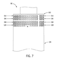
さらに、図7は、図6の燃料ノズルの1つ(例えば、92)の例示的実施形態の矢視7−7部分側断面図であり、圧縮空気38の軸方向に均一な分布を示す。特に、燃料ノズル92に対して、空気速度ベクトル114、116、118、及び120が、燃料ノズル92の長さに沿った複数の軸方向位置に例示されている。特に、空気速度ベクトル114は燃料ノズル92のヘッドエンド122付近であってもよく、空気速度ベクトル120は燃料ノズル92の燃焼器端部124付近であってもよい。言い換えれば、空気速度ベクトル120の方が、圧縮空気38がヘッドエンド領域34に入る場所に近くてもよい一方で、空気速度ベクトル114の方が、圧縮空気38がヘッドエンド領域34に入る場所から遠くてもよい。
In addition, FIG. 7 is a partial cross-sectional side view of the exemplary embodiment of one of the fuel nozzles of FIG. 6 (eg, 92) taken along the line 7-7, showing a uniform distribution of the
図7に示すように、空気速度ベクトル114、116、118、及び120の大きさはすべて、実質的に同様なことがある。言い換えれば、空気速度は、対応する軸方向位置のそれぞれにおいて実質的に同じであることがある。これは、燃料ノズル92に対して、圧縮空気38がどのように軸方向により均一に分散され得るかを例示している。
As shown in FIG. 7, the magnitudes of the
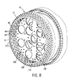
次に図5に戻って、ヘッドエンド領域34の空気室68を仕切板126(別の状況では「キャップ」として知られる)によって燃焼器16から分離してもよい。図8は、仕切板126及び空気流整流器50の例示的実施形態の斜視図である。図8に示すように、仕切板126は、燃料ノズル12を収容して支持するための複数の開口部128を備えていてもよい。特に、開口部128は、燃料ノズル12の外部の円筒壁に対して封止を形成するように構成してもよい。ある実施形態では、図に示すように、空気流整流器50に付随する有孔円筒82が仕切板126に接続していてもよい。さらに、ある実施形態では、燃料ノズル12を副仕切板132の開口部130間に配置して、ヘッドエンド領域34の空気室68を燃焼器16からさらに隔離してもよい。ある実施形態では、仕切板126、132間のスペースに予混合アセンブリを配置してもよい。
Returning now to FIG. 5, the
前述したように、空気流整流器50の有孔転向羽根70によって、ヘッドエンド領域34の燃料ノズル12間において圧縮空気38の均一な分布が可能になることがある。図8に示すように、有孔転向羽根70は、軸46の周りの周方向において断面が実質的に一定である円環形状を備えていてもよい。しかし、環状の有孔転向羽根70の特定の断面プロファイルは変わってもよい。例えば、穿孔の幾何形状、分布、及び穿孔のサイズは、軸46に対して軸方向、半径方向、及び/又は周方向において一定でも可変でもよい。例示した実施形態では、有孔環状壁72上の穿孔73は、有孔円筒82上の穿孔83よりも、サイズが小さく、より密接に互いに詰められている。さらに、穿孔73は直径が一定であり、一方で、穿孔83は上流方向に直径が小さくなっている。穿孔の幾何形状、分布、及び穿孔のサイズの他の様々な組み合わせも実施してよい。
As described above, the
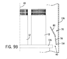
図9A〜9Hは、空気流整流器50の有孔転向羽根70の例示的実施形態の部分断面プロファイル図である。図9Aに、図3及び図4に示す空気流整流器50に対応する有孔転向羽根70の部分断面プロファイルを示す。具体的には、例示した有孔転向羽根70は、第1の有孔環状壁78と、第1の有孔環状壁78が接続される第2の有孔環状壁80とを備える。例示した実施形態では、第1の有孔環状壁78はヘッドエンド領域34の中央の長手軸46に向かって徐々に集束しているだけであり、一方で、第2の有孔壁80は中央の長手軸46に向かってより急激に収束している。しかし一般的に、有孔転向羽根70の例示した実施形態が備える断面プロファイルは、2つの直線的に収束する有孔壁部分78、80を備えるものである。例示した実施形態では、第1の有孔環状壁78の前縁134はヘッドエンド領域34の外壁136の内面に接続していてもよい。しかし、図9Bに示すように、第1の有孔環状壁78の前縁134はヘッドエンド領域34の外壁136に接続していなくてもよい。さらに、ある実施形態では、第1の有孔環状壁78の前縁134を、圧縮空気38がヘッドエンド領域34に流れ込むときに通る環状通路40内の半径方向中心に置いてもよい。この結果、有孔転向羽根70の周りの空気流に対して環状の間隙が形成されてもよい。
9A-9H are partial cross-sectional profile views of an exemplary embodiment of the perforated turning
図9Cに、図5及び図8に示す空気流整流器50と一致する有孔転向羽根70の部分断面プロファイルを示す。具体的には、例示した有孔転向羽根70は、湾曲形有孔環状壁138を備える。例示した実施形態では、湾曲形有孔環状壁138は、ヘッドエンド領域34の中央の長手軸46に向かう凹面形状である。しかし他の実施形態では、その代わりに、湾曲形有孔環状壁138はわずかに凸面であってもよい。さらに、ある実施形態では、有孔転向羽根70は、様々な程度の湾曲(例えば、C形状、U形状、J形状、S形状など)を伴う複数の壁部分を備えていてもよい。例示した実施形態では、湾曲形有孔環状壁138の前縁140はヘッドエンド領域34の外壁136に接続していてもよい。しかし、図9Dに示すように、湾曲形有孔環状壁138の前縁140はヘッドエンド領域34の外壁136に接続していなくてもよい。さらに、ある実施形態では、湾曲形有孔環状壁138の前縁140を、圧縮空気38がヘッドエンド領域34に流れ込むときに通る環状通路40内の半径方向中心に置いてもよい。この場合もやはり、これによって、有孔転向羽根70の周りの空気流に対して環状の間隙が形成されることがある。
FIG. 9C shows a partial cross-sectional profile of the perforated turning
しかし、これらの直線及び曲線断面は、有孔転向羽根70に対して用いてもよい断面のタイプの一部でしかない。さらに、より複雑な形状を用いてもよい。例えば、図9Eに、L字形有孔転向羽根70に対する部分断面プロファイルを示す。図に示すように、有孔転向羽根70は、ヘッドエンド領域34の中央の長手軸46に向かって直線的に収束する第1の有孔壁142と、第1の有孔壁142に接続され、やはり中央の長手軸46に向かって直線的に収束する第2の有孔壁144とを備えていてもよい。しかし第2の有孔壁144は、仕切板126に向かって後方を向き、第1の有孔壁142と第2の有孔壁144との間でL字形部分を形成している。ある実施形態では、第1の有孔壁142と第2の有孔壁144との間の形状は略三角形であってもよいが、第1及び第2の有孔壁142、144は完全に直線でなくてもよい。むしろ、第1及び第2の有孔壁142、144は曲線であるがそれでも両者の間に略三角形が形成されている状態であってもよい。図9A〜9Dに関して前述したように、有孔転向羽根70の前縁146は、ヘッドエンド領域34の外壁136に接続していてもよいし接続されていなくてもよい。
However, these straight and curved cross sections are only some of the types of cross sections that may be used for
図9Fに、フック形有孔転向羽根70に対する部分断面プロファイルを示す。図に示すように、有孔転向羽根70は、ヘッドエンド領域34の中央の長手軸46に向かって直線的に収束する第1の有孔壁148と、第1の有孔壁148に接続され、やはり中央の長手軸46に向かって直線的に収束する第2の有孔壁150とを備えていてもよい。しかし第2の有孔壁150は、仕切板126に向かって後方を向いている。さらに、空気流整流器50は、第3の有孔壁152を備えていてもよい。第3の有孔壁152は、第2の有孔壁150に接続しているが、中央の長手軸46から離れるように発散する一方で、ヘッドエンド領域34の外壁136に向かって後方を向き、第1の有孔壁148と第2の有孔壁150と第3の有孔壁152との間にフック形部分を形成している。ある実施形態では、第1の有孔壁148と第2の有孔壁150と第3の有孔壁152との間の形状は略矩形であってもよいが、第1、第2、及び第3の有孔壁148、150、152は完全に直線になっていなくてもよい。むしろ、第1、第2、及び第3の有孔壁148、150、152は曲線であるがそれでもそれらの間に略矩形形状が形成されている状態であってもよい。この場合もやはり、図9A〜9Dに関して前述したように、有孔転向羽根70の前縁154は、ヘッドエンド領域34の外壁136に接続していてもよいし接続されていなくてもよい。
FIG. 9F shows a partial cross-sectional profile for the hook-shaped
図9G及び9Hに、有孔転向羽根70に対するある程度同様の他の2つの部分断面プロファイルを示す。例えば、図9Gに示すのは、3/4トーラス158を伴う有孔壁156を備える有孔転向羽根70の部分断面プロファイルである。さらに、他の量の湾曲(例えば、一周の少なくとも50、60、70、80、又は90%)の有孔壁156を用いてもよい。こうして有孔壁156は、略環状の仕方でそれ自体に向かって後方に丸くなっている。同様に、図9Hに、圧縮空気38がヘッドエンド領域34に流れ込むときに通る環状通路40に向かって後方を向く湾曲形後縁162を伴う有孔壁160を備える有孔転向羽根70の部分断面プロファイルを示す。これらの実施形態のそれぞれに対して、有孔転向羽根70の断面プロファイルの特定の形状は変わってもよい。しかし一般的に、実施形態は、湾曲形有孔壁の後縁が環状通路40に向かって後方を向く有孔転向羽根70の断面プロファイルを備える。この場合もやはり、図9A〜9Dに関して前述したように、図9G及び9Hに示す有孔転向羽根70の前縁164、166は、ヘッドエンド領域34の外壁136に接続していてもよいし接続されていなくてもよい。
9G and 9H show two other partial cross-sectional profiles that are somewhat similar to the perforated turning
図9E〜9Hに示す有孔転向羽根70の実施形態のそれぞれは、圧縮空気38の流れがヘッドエンド領域34の空気室68に入ることをある程度まで直接妨げることがある後縁の特定の特徴を共有している。例えば、図10は、有孔転向羽根70の例示的実施形態の一部の斜視図である。具体的には、図10に示す有孔転向羽根70は図9Hの有孔転向羽根70であり、圧縮空気38がヘッドエンド領域34に流れ込むときに通る環状通路40に向かって後方を向く湾曲形後縁162を備えるものである。圧縮空気38がヘッドエンド領域34の空気室68に入るときに、湾曲形後縁162によって圧縮空気38の流れが実質的に妨げられることがある。これをある程度軽減するために、後縁162は「城構え」又は「ジグザグ形」の設計を備えていてもよい。この設計は、後縁162において切り取り部分168を含んでいる。ある実施形態では、切り取り部分168は矩形であってもよいが、他の切り取り部分形状(例えば、三角形、円形など)を用いてもよい。切り取り部分168によって、圧縮空気38の完全速度が後縁162において発生することが防止されることがある。
Each of the perforated turning
逆に、図9A〜9Hに記載された有孔転向羽根70のある実施形態は、圧縮空気38の流れがヘッドエンド領域34の空気室68に入ることをある程度まで直接妨げる後縁を備えてはいない。例えば、図9A〜9Dに示す有孔転向羽根70の実施形態は、圧縮空気38を空気室68により徐々に送り直す断面プロファイルを備えている。こうして図9A〜9Dに示す実施形態は、ある実施形態では、有孔壁の代わりに一枚壁を用いてもよい。一枚壁を用いると、圧縮空気38を案内羽根70の壁を通して送ることができないことがあるが、一枚壁によってやはり、圧縮空気38がヘッドエンド領域34の中央の長手軸46に向かって送り直されるため、燃料ノズル12に対する空気分布の均一化を促進する。また、穿孔を用いる実施形態では、穿孔のサイズ、数、及び分布を変えてもよい。
Conversely, certain embodiments of the perforated turning
本明細書に記載した空気流整流器50の実施形態は、多くの方法で有益なことがある。特に、空気流整流器50によって燃料ノズル12間で圧縮空気38のより均一な分布が形成されるため、同様に、均一な静圧場が燃料ノズル12の空気入口の周りに存在する。さらに、均一な静圧によって、すべての燃料ノズル12を通る均衡した空気質量流が可能になり、その結果、空気及び燃料の混合の均一化を促進する。さらに、各燃料ノズル12は実質的に同様の量の空気流を受けるため、単一の燃料ノズル12の設計を用いてもよく、その結果、ハードウェア又は初期コスト費用が下がる。さらに、空気及び燃料の混合がより一定になるため、排出が改善されることがある。他の利益として、燃料ノズル12における空気プロファイルがより均一であることを挙げてもよい。この結果、燃料ノズル12の保炎性能をより良好にすることができる。特に、燃料ノズル12における空気プロファイルがより均一であるために、速度が低下したゾーンが生じる可能性は低い。このようなゾーンがあると、火炎が燃料ノズル12の内部に固定されてハードウェアを破壊する可能性がある。
The
本明細書の説明では、例を用いて、最良の形態を含む本発明を開示するとともに、当業者も本発明を実施できるように、例えば任意の装置又はシステムを作り及び用いること、並びに取り入れられた任意の方法を行なうことができるようにしている。本発明の特許可能な範囲は、請求項によって規定されるとともに、当業者に想起される他の例を含んでもよい。このような他の例は、請求項の文字通りの言葉使いと違わない構造要素を有するか、又は請求項の文字通りの言葉使いとの差が非実質的である均等な構造要素を含む場合には、請求項の範囲内であることが意図されている。 The description herein uses examples to disclose the invention, including the best mode, and to make and use, for example, any apparatus or system that enables those skilled in the art to practice the invention. Any way you can do it. The patentable scope of the invention is defined by the claims, and may include other examples that occur to those skilled in the art. Such other examples have structural elements that do not differ from the literal wording of the claim, or include equivalent structural elements that are insubstantial to the literal wording of the claim. It is intended to be within the scope of the claims.
Claims (9)
燃焼室(52)と、
燃焼室(52)の周囲に設けられたライナ(44)と、
ライナ(44)の周囲に設けられたスリーブ(42)と、
ライナ(44)とスリーブ(42)の間の空気供給経路(38)と、
空気室(68)と、
燃焼器の長手軸に関して軸方向に燃焼室(52)と空気室(68)との間に設けられた仕切板(126)と、
仕切板(126)を通って延在する燃料ノズル(12)であって、空気室(68)内の空気入口と燃焼室(52)内の出口とを有する燃料ノズル(12)と、
空気室(68)への空気供給経路(38)に沿って空気室(68)に配置された空気流整流器(50)であって、長手軸を中心として空気供給経路(38)と重なる半径方向位置で周方向に延在する第1の有孔転向壁(70)を備える空気流整流器(50)と
を備えており、第1の有効転向壁(70)が、燃焼室(52)から上流方向に向かって空気供給経路(38)を流れる空気流の第1の部分(84)を通過させるように構成された第1の複数の開口を有しているとともに、第1の有効転向壁(70)が空気供給経路(38)から上流に長手軸に向かって内側に傾斜していていて空気供給経路(38)からの空気流の第2の部分(88)を空気室(68)の中央部に向けて内側に転向させる、システム。 A system Ru comprising a turbine engine (10), a combustor provided in the turbine engine (10) (16),
A combustion chamber (52);
A liner (44) provided around the combustion chamber (52);
A sleeve (42) provided around the liner (44);
An air supply path (38) between the liner (44) and the sleeve (42);
An air chamber (68);
A partition plate (126) provided between the combustion chamber (52) and the air chamber (68) in the axial direction with respect to the longitudinal axis of the combustor;
A fuel nozzle (12) extending through the partition plate (126) having an air inlet in the air chamber (68) and an outlet in the combustion chamber (52);
An air chamber (68) to place air flow rectifiers along the air supply path of the air chamber (68) (38) (50), radially overlapping the air supply path (38) about the longitudinal axis An air flow rectifier (50) comprising a first perforated turning wall (70) extending circumferentially at a position;
So that the first effective turning wall (70) passes the first portion (84) of the airflow flowing through the air supply path (38) from the combustion chamber (52) in the upstream direction. An air supply path having a first plurality of openings configured and having a first effective turning wall (70) inclined inward toward the longitudinal axis upstream from the air supply path (38). the second portion of the air flow from (38) to (88) deflect inwardly towards the central portion of the air chamber (68), the system.
A plurality of fuel nozzles (12) extending through the divider plate (126) is provided, and the airflow rectifier (50) is configured to evenly distribute the airflow among the plurality of fuel nozzles (12). The system according to any one of claims 1 to 8.
Applications Claiming Priority (2)
| Application Number | Priority Date | Filing Date | Title |
|---|---|---|---|
| US12/434,505 | 2009-05-01 | ||
| US12/434,505 US8234872B2 (en) | 2009-05-01 | 2009-05-01 | Turbine air flow conditioner |
Publications (3)
| Publication Number | Publication Date |
|---|---|
| JP2010261706A JP2010261706A (en) | 2010-11-18 |
| JP2010261706A5 JP2010261706A5 (en) | 2013-06-13 |
| JP5485006B2 true JP5485006B2 (en) | 2014-05-07 |
Family
ID=42813871
Family Applications (1)
| Application Number | Title | Priority Date | Filing Date |
|---|---|---|---|
| JP2010104701A Expired - Fee Related JP5485006B2 (en) | 2009-05-01 | 2010-04-30 | Turbine airflow rectifier |
Country Status (5)
| Country | Link |
|---|---|
| US (1) | US8234872B2 (en) |
| JP (1) | JP5485006B2 (en) |
| CN (1) | CN101876437A (en) |
| CH (1) | CH700993A8 (en) |
| DE (1) | DE102010016543A1 (en) |
Families Citing this family (58)
| Publication number | Priority date | Publication date | Assignee | Title |
|---|---|---|---|---|
| US8522555B2 (en) * | 2009-05-20 | 2013-09-03 | General Electric Company | Multi-premixer fuel nozzle support system |
| US20110000215A1 (en) * | 2009-07-01 | 2011-01-06 | General Electric Company | Combustor Can Flow Conditioner |
| CN102422083B (en) * | 2009-08-13 | 2014-07-16 | 三菱重工业株式会社 | Combustor |
| US8590311B2 (en) * | 2010-04-28 | 2013-11-26 | General Electric Company | Pocketed air and fuel mixing tube |
| US8991187B2 (en) * | 2010-10-11 | 2015-03-31 | General Electric Company | Combustor with a lean pre-nozzle fuel injection system |
| US9423132B2 (en) * | 2010-11-09 | 2016-08-23 | Opra Technologies B.V. | Ultra low emissions gas turbine combustor |
| TWI429854B (en) * | 2010-12-17 | 2014-03-11 | Grand Mate Co Ltd | Detection and Compensation of Gas Safety Supply |
| JP6110854B2 (en) * | 2011-08-22 | 2017-04-05 | トクァン,マジェドTOQAN, Majed | Tangential annular combustor with premixed fuel air for use in gas turbine engines |
| US9267687B2 (en) | 2011-11-04 | 2016-02-23 | General Electric Company | Combustion system having a venturi for reducing wakes in an airflow |
| US8899975B2 (en) | 2011-11-04 | 2014-12-02 | General Electric Company | Combustor having wake air injection |
| US9033699B2 (en) * | 2011-11-11 | 2015-05-19 | General Electric Company | Combustor |
| US8438851B1 (en) * | 2012-01-03 | 2013-05-14 | General Electric Company | Combustor assembly for use in a turbine engine and methods of assembling same |
| US9134023B2 (en) * | 2012-01-06 | 2015-09-15 | General Electric Company | Combustor and method for distributing fuel in the combustor |
| US20130192234A1 (en) * | 2012-01-26 | 2013-08-01 | General Electric Company | Bundled multi-tube nozzle assembly |
| US9163839B2 (en) * | 2012-03-19 | 2015-10-20 | General Electric Company | Micromixer combustion head end assembly |
| US9353949B2 (en) | 2012-04-17 | 2016-05-31 | Siemens Energy, Inc. | Device for improved air and fuel distribution to a combustor |
| US9534781B2 (en) | 2012-05-10 | 2017-01-03 | General Electric Company | System and method having multi-tube fuel nozzle with differential flow |
| US20140182304A1 (en) * | 2012-12-28 | 2014-07-03 | Exxonmobil Upstream Research Company | System and method for a turbine combustor |
| US9803865B2 (en) | 2012-12-28 | 2017-10-31 | General Electric Company | System and method for a turbine combustor |
| WO2014071120A2 (en) * | 2012-11-02 | 2014-05-08 | General Electric Company | System and method for a turbine combustor |
| US9631815B2 (en) * | 2012-12-28 | 2017-04-25 | General Electric Company | System and method for a turbine combustor |
| WO2014071123A2 (en) * | 2012-11-02 | 2014-05-08 | General Electric Company | System and method for a turbine combustor |
| US20140123649A1 (en) * | 2012-11-07 | 2014-05-08 | Juan E. Portillo Bilbao | Acoustic damping system for a combustor of a gas turbine engine |
| US9151503B2 (en) | 2013-01-04 | 2015-10-06 | General Electric Company | Coaxial fuel supply for a micromixer |
| US9765973B2 (en) | 2013-03-12 | 2017-09-19 | General Electric Company | System and method for tube level air flow conditioning |
| US9528444B2 (en) | 2013-03-12 | 2016-12-27 | General Electric Company | System having multi-tube fuel nozzle with floating arrangement of mixing tubes |
| US9534787B2 (en) | 2013-03-12 | 2017-01-03 | General Electric Company | Micromixing cap assembly |
| US9228747B2 (en) * | 2013-03-12 | 2016-01-05 | Pratt & Whitney Canada Corp. | Combustor for gas turbine engine |
| US9671112B2 (en) | 2013-03-12 | 2017-06-06 | General Electric Company | Air diffuser for a head end of a combustor |
| US9759425B2 (en) * | 2013-03-12 | 2017-09-12 | General Electric Company | System and method having multi-tube fuel nozzle with multiple fuel injectors |
| US9651259B2 (en) | 2013-03-12 | 2017-05-16 | General Electric Company | Multi-injector micromixing system |
| US9546789B2 (en) * | 2013-03-15 | 2017-01-17 | General Electric Company | System having a multi-tube fuel nozzle |
| US9303873B2 (en) | 2013-03-15 | 2016-04-05 | General Electric Company | System having a multi-tube fuel nozzle with a fuel nozzle housing |
| US9784452B2 (en) | 2013-03-15 | 2017-10-10 | General Electric Company | System having a multi-tube fuel nozzle with an aft plate assembly |
| JP6239247B2 (en) * | 2013-03-15 | 2017-11-29 | 三菱重工業株式会社 | Gas turbine combustor |
| US9316397B2 (en) | 2013-03-15 | 2016-04-19 | General Electric Company | System and method for sealing a fuel nozzle |
| US9291352B2 (en) * | 2013-03-15 | 2016-03-22 | General Electric Company | System having a multi-tube fuel nozzle with an inlet flow conditioner |
| US9322553B2 (en) | 2013-05-08 | 2016-04-26 | General Electric Company | Wake manipulating structure for a turbine system |
| US9739201B2 (en) | 2013-05-08 | 2017-08-22 | General Electric Company | Wake reducing structure for a turbine system and method of reducing wake |
| US9435221B2 (en) | 2013-08-09 | 2016-09-06 | General Electric Company | Turbomachine airfoil positioning |
| US10436039B2 (en) * | 2013-11-11 | 2019-10-08 | United Technologies Corporation | Gas turbine engine turbine blade tip cooling |
| US20150338101A1 (en) * | 2014-05-21 | 2015-11-26 | General Electric Company | Turbomachine combustor including a combustor sleeve baffle |
| US9803864B2 (en) * | 2014-06-24 | 2017-10-31 | General Electric Company | Turbine air flow conditioner |
| US9964308B2 (en) * | 2014-08-19 | 2018-05-08 | General Electric Company | Combustor cap assembly |
| US9835333B2 (en) * | 2014-12-23 | 2017-12-05 | General Electric Company | System and method for utilizing cooling air within a combustor |
| US10139109B2 (en) | 2016-01-07 | 2018-11-27 | Siemens Energy, Inc. | Can-annular combustor burner with non-uniform airflow mitigation flow conditioner |
| US20170226929A1 (en) * | 2016-02-09 | 2017-08-10 | General Electric Company | Fuel injector covers and methods of fabricating same |
| JP6723768B2 (en) * | 2016-03-07 | 2020-07-15 | 三菱重工業株式会社 | Burner assembly, combustor, and gas turbine |
| CN108869041B (en) * | 2017-05-12 | 2020-07-14 | 中国联合重型燃气轮机技术有限公司 | Front end steering scoop for a gas turbine |
| CN107166389A (en) * | 2017-06-29 | 2017-09-15 | 佛山市豹鼎厨具设备有限公司 | A kind of gas burner |
| US10969107B2 (en) * | 2017-09-15 | 2021-04-06 | General Electric Company | Turbine engine assembly including a rotating detonation combustor |
| US10890329B2 (en) | 2018-03-01 | 2021-01-12 | General Electric Company | Fuel injector assembly for gas turbine engine |
| US10935245B2 (en) | 2018-11-20 | 2021-03-02 | General Electric Company | Annular concentric fuel nozzle assembly with annular depression and radial inlet ports |
| US11286884B2 (en) | 2018-12-12 | 2022-03-29 | General Electric Company | Combustion section and fuel injector assembly for a heat engine |
| US11073114B2 (en) | 2018-12-12 | 2021-07-27 | General Electric Company | Fuel injector assembly for a heat engine |
| US11156360B2 (en) | 2019-02-18 | 2021-10-26 | General Electric Company | Fuel nozzle assembly |
| JP6841968B1 (en) * | 2020-09-04 | 2021-03-10 | 三菱パワー株式会社 | Perforated plate of gas turbine combustor, gas turbine combustor and gas turbine |
| CN113091093A (en) * | 2021-05-13 | 2021-07-09 | 中国联合重型燃气轮机技术有限公司 | Air dome and nozzle for gas turbine |
Family Cites Families (11)
| Publication number | Priority date | Publication date | Assignee | Title |
|---|---|---|---|---|
| DE69916911T2 (en) * | 1998-02-10 | 2005-04-21 | Gen Electric | Burner with uniform fuel / air premix for low-emission combustion |
| JP3364169B2 (en) * | 1999-06-09 | 2003-01-08 | 三菱重工業株式会社 | Gas turbine and its combustor |
| DE10050248A1 (en) * | 2000-10-11 | 2002-04-18 | Alstom Switzerland Ltd | Pre-mixing burner comprises swirl burner with inner chamber, with widening passage, injector with adjustable elements. |
| US6438959B1 (en) * | 2000-12-28 | 2002-08-27 | General Electric Company | Combustion cap with integral air diffuser and related method |
| US7377036B2 (en) * | 2004-10-05 | 2008-05-27 | General Electric Company | Methods for tuning fuel injection assemblies for a gas turbine fuel nozzle |
| US8062027B2 (en) * | 2005-08-11 | 2011-11-22 | Elster Gmbh | Industrial burner and method for operating an industrial burner |
| US7770395B2 (en) * | 2006-02-27 | 2010-08-10 | Mitsubishi Heavy Industries, Ltd. | Combustor |
| US7762074B2 (en) * | 2006-04-04 | 2010-07-27 | Siemens Energy, Inc. | Air flow conditioner for a combustor can of a gas turbine engine |
| US20080104961A1 (en) * | 2006-11-08 | 2008-05-08 | Ronald Scott Bunker | Method and apparatus for enhanced mixing in premixing devices |
| US8117845B2 (en) * | 2007-04-27 | 2012-02-21 | General Electric Company | Systems to facilitate reducing flashback/flame holding in combustion systems |
| US20100260591A1 (en) * | 2007-06-08 | 2010-10-14 | General Electric Company | Spanwise split variable guide vane and related method |
-
2009
- 2009-05-01 US US12/434,505 patent/US8234872B2/en not_active Expired - Fee Related
-
2010
- 2010-04-20 DE DE102010016543A patent/DE102010016543A1/en not_active Withdrawn
- 2010-04-28 CH CH00631/10A patent/CH700993A8/en not_active Application Discontinuation
- 2010-04-30 CN CN2010101753240A patent/CN101876437A/en active Pending
- 2010-04-30 JP JP2010104701A patent/JP5485006B2/en not_active Expired - Fee Related
Also Published As
| Publication number | Publication date |
|---|---|
| US8234872B2 (en) | 2012-08-07 |
| CH700993A2 (en) | 2010-11-15 |
| JP2010261706A (en) | 2010-11-18 |
| DE102010016543A1 (en) | 2010-11-04 |
| CH700993A8 (en) | 2011-01-31 |
| US20100275601A1 (en) | 2010-11-04 |
| CN101876437A (en) | 2010-11-03 |
Similar Documents
| Publication | Publication Date | Title |
|---|---|---|
| JP5485006B2 (en) | Turbine airflow rectifier | |
| JP6203530B2 (en) | Fuel / air premixing system for turbine engines | |
| US8850821B2 (en) | System for fuel injection in a fuel nozzle | |
| JP6059424B2 (en) | Curved contour axial direction-radial diffuser | |
| JP5883594B2 (en) | Turbine exhaust plenum | |
| JP5631627B2 (en) | Multi-premixer fuel nozzle support system | |
| JP5947515B2 (en) | Turbomachine with mixing tube element with vortex generator | |
| US9297535B2 (en) | Fuel/air mixing system for fuel nozzle | |
| JP2010276334A (en) | Method and device for injecting air and fuel in turbine | |
| US20120111013A1 (en) | System for directing air flow in a fuel nozzle assembly | |
| EP3303929B1 (en) | Combustor arrangement | |
| JP6200678B2 (en) | Turbine combustor system with aerodynamic feed cap | |
| JP6826792B2 (en) | Fuel nozzle assembly | |
| JP2009047411A (en) | Turbo machine diffuser | |
| JP2011094951A (en) | Apparatus for conditioning airflow passing through nozzle | |
| US10012098B2 (en) | Mid-section of a can-annular gas turbine engine to introduce a radial velocity component into an air flow discharged from a compressor of the mid-section | |
| JP2016166728A (en) | Air shield for fuel injector of combustor | |
| JP2013253769A (en) | Combustor assembly having fuel pre-mixer | |
| US10550729B2 (en) | Asymmetric gas turbine exhaust diffuser | |
| US9803864B2 (en) | Turbine air flow conditioner | |
| US20130081731A1 (en) | Exhaust gas diffuser | |
| US11215364B2 (en) | Combustor, gas turbine | |
| US20190353054A1 (en) | Exhaust system for a gas turbine engine | |
| US11209163B2 (en) | Gas turbine combustor, manufacturing method for gas turbine and gas turbine combustor |
Legal Events
| Date | Code | Title | Description |
|---|---|---|---|
| A521 | Written amendment |
Free format text: JAPANESE INTERMEDIATE CODE: A523 Effective date: 20130425 |
|
| A621 | Written request for application examination |
Free format text: JAPANESE INTERMEDIATE CODE: A621 Effective date: 20130425 |
|
| TRDD | Decision of grant or rejection written | ||
| A01 | Written decision to grant a patent or to grant a registration (utility model) |
Free format text: JAPANESE INTERMEDIATE CODE: A01 Effective date: 20140121 |
|
| A977 | Report on retrieval |
Free format text: JAPANESE INTERMEDIATE CODE: A971007 Effective date: 20140123 |
|
| A61 | First payment of annual fees (during grant procedure) |
Free format text: JAPANESE INTERMEDIATE CODE: A61 Effective date: 20140219 |
|
| R150 | Certificate of patent or registration of utility model |
Ref document number: 5485006 Country of ref document: JP Free format text: JAPANESE INTERMEDIATE CODE: R150 |
|
| LAPS | Cancellation because of no payment of annual fees |