JP5484904B2 - Method and apparatus for transmitting radiation pressure caused by light waves - Google Patents
Method and apparatus for transmitting radiation pressure caused by light waves Download PDFInfo
- Publication number
- JP5484904B2 JP5484904B2 JP2009521849A JP2009521849A JP5484904B2 JP 5484904 B2 JP5484904 B2 JP 5484904B2 JP 2009521849 A JP2009521849 A JP 2009521849A JP 2009521849 A JP2009521849 A JP 2009521849A JP 5484904 B2 JP5484904 B2 JP 5484904B2
- Authority
- JP
- Japan
- Prior art keywords
- light
- prism
- engine
- modeling
- energy
- Prior art date
- Legal status (The legal status is an assumption and is not a legal conclusion. Google has not performed a legal analysis and makes no representation as to the accuracy of the status listed.)
- Active
Links
- 230000005855 radiation Effects 0.000 title claims description 48
- 238000000034 method Methods 0.000 title claims description 40
- 230000003287 optical effect Effects 0.000 claims description 70
- 230000006835 compression Effects 0.000 claims description 27
- 238000007906 compression Methods 0.000 claims description 27
- 230000005540 biological transmission Effects 0.000 claims description 21
- 238000010521 absorption reaction Methods 0.000 claims description 18
- 230000004907 flux Effects 0.000 claims description 12
- 238000004364 calculation method Methods 0.000 claims description 4
- 238000010438 heat treatment Methods 0.000 claims description 4
- 238000009825 accumulation Methods 0.000 claims description 2
- 238000012545 processing Methods 0.000 claims description 2
- 239000010453 quartz Substances 0.000 description 50
- VYPSYNLAJGMNEJ-UHFFFAOYSA-N silicon dioxide Inorganic materials O=[Si]=O VYPSYNLAJGMNEJ-UHFFFAOYSA-N 0.000 description 50
- 230000006870 function Effects 0.000 description 22
- 238000010586 diagram Methods 0.000 description 21
- 239000000463 material Substances 0.000 description 15
- 230000000903 blocking effect Effects 0.000 description 13
- 238000013461 design Methods 0.000 description 12
- 230000007246 mechanism Effects 0.000 description 12
- 230000005684 electric field Effects 0.000 description 8
- 238000006243 chemical reaction Methods 0.000 description 7
- 238000012546 transfer Methods 0.000 description 7
- 230000002441 reversible effect Effects 0.000 description 6
- 230000002123 temporal effect Effects 0.000 description 6
- 238000002834 transmittance Methods 0.000 description 6
- 230000008859 change Effects 0.000 description 5
- 230000000694 effects Effects 0.000 description 5
- 238000002310 reflectometry Methods 0.000 description 5
- 230000008901 benefit Effects 0.000 description 4
- 230000003321 amplification Effects 0.000 description 3
- 230000003993 interaction Effects 0.000 description 3
- 238000003199 nucleic acid amplification method Methods 0.000 description 3
- 230000008569 process Effects 0.000 description 3
- 239000000243 solution Substances 0.000 description 3
- 238000001228 spectrum Methods 0.000 description 3
- 230000004075 alteration Effects 0.000 description 2
- 238000013459 approach Methods 0.000 description 2
- 239000003638 chemical reducing agent Substances 0.000 description 2
- 239000013078 crystal Substances 0.000 description 2
- 230000005611 electricity Effects 0.000 description 2
- 230000004048 modification Effects 0.000 description 2
- 238000012986 modification Methods 0.000 description 2
- 230000009467 reduction Effects 0.000 description 2
- 238000011946 reduction process Methods 0.000 description 2
- 238000004088 simulation Methods 0.000 description 2
- 239000007787 solid Substances 0.000 description 2
- 239000011800 void material Substances 0.000 description 2
- RYGMFSIKBFXOCR-UHFFFAOYSA-N Copper Chemical compound [Cu] RYGMFSIKBFXOCR-UHFFFAOYSA-N 0.000 description 1
- 230000009471 action Effects 0.000 description 1
- 230000003213 activating effect Effects 0.000 description 1
- 230000002776 aggregation Effects 0.000 description 1
- 238000004220 aggregation Methods 0.000 description 1
- 238000004458 analytical method Methods 0.000 description 1
- 230000002457 bidirectional effect Effects 0.000 description 1
- 230000008602 contraction Effects 0.000 description 1
- 229910052802 copper Inorganic materials 0.000 description 1
- 239000010949 copper Substances 0.000 description 1
- 230000008878 coupling Effects 0.000 description 1
- 238000010168 coupling process Methods 0.000 description 1
- 238000005859 coupling reaction Methods 0.000 description 1
- 230000003247 decreasing effect Effects 0.000 description 1
- 230000001419 dependent effect Effects 0.000 description 1
- 239000006185 dispersion Substances 0.000 description 1
- 238000006073 displacement reaction Methods 0.000 description 1
- 238000004146 energy storage Methods 0.000 description 1
- 238000005516 engineering process Methods 0.000 description 1
- 230000005284 excitation Effects 0.000 description 1
- 230000005669 field effect Effects 0.000 description 1
- 230000006872 improvement Effects 0.000 description 1
- 210000003000 inclusion body Anatomy 0.000 description 1
- 230000000977 initiatory effect Effects 0.000 description 1
- 238000002347 injection Methods 0.000 description 1
- 239000007924 injection Substances 0.000 description 1
- 230000010354 integration Effects 0.000 description 1
- 230000001678 irradiating effect Effects 0.000 description 1
- 230000031700 light absorption Effects 0.000 description 1
- 238000004519 manufacturing process Methods 0.000 description 1
- 239000002245 particle Substances 0.000 description 1
- 230000010287 polarization Effects 0.000 description 1
- 238000010248 power generation Methods 0.000 description 1
- 230000001902 propagating effect Effects 0.000 description 1
- 230000036962 time dependent Effects 0.000 description 1
- 230000007704 transition Effects 0.000 description 1
- 230000005641 tunneling Effects 0.000 description 1
- 230000037303 wrinkles Effects 0.000 description 1
Images


Classifications
-
- G—PHYSICS
- G01—MEASURING; TESTING
- G01J—MEASUREMENT OF INTENSITY, VELOCITY, SPECTRAL CONTENT, POLARISATION, PHASE OR PULSE CHARACTERISTICS OF INFRARED, VISIBLE OR ULTRAVIOLET LIGHT; COLORIMETRY; RADIATION PYROMETRY
- G01J1/00—Photometry, e.g. photographic exposure meter
- G01J1/56—Photometry, e.g. photographic exposure meter using radiation pressure or radiometer effect
-
- F—MECHANICAL ENGINEERING; LIGHTING; HEATING; WEAPONS; BLASTING
- F03—MACHINES OR ENGINES FOR LIQUIDS; WIND, SPRING, OR WEIGHT MOTORS; PRODUCING MECHANICAL POWER OR A REACTIVE PROPULSIVE THRUST, NOT OTHERWISE PROVIDED FOR
- F03G—SPRING, WEIGHT, INERTIA OR LIKE MOTORS; MECHANICAL-POWER PRODUCING DEVICES OR MECHANISMS, NOT OTHERWISE PROVIDED FOR OR USING ENERGY SOURCES NOT OTHERWISE PROVIDED FOR
- F03G6/00—Devices for producing mechanical power from solar energy
- F03G6/06—Devices for producing mechanical power from solar energy with solar energy concentrating means
- F03G6/062—Parabolic point or dish concentrators
-
- G—PHYSICS
- G02—OPTICS
- G02B—OPTICAL ELEMENTS, SYSTEMS OR APPARATUS
- G02B17/00—Systems with reflecting surfaces, with or without refracting elements
- G02B17/004—Systems comprising a plurality of reflections between two or more surfaces, e.g. cells, resonators
-
- G—PHYSICS
- G02—OPTICS
- G02B—OPTICAL ELEMENTS, SYSTEMS OR APPARATUS
- G02B26/00—Optical devices or arrangements for the control of light using movable or deformable optical elements
- G02B26/08—Optical devices or arrangements for the control of light using movable or deformable optical elements for controlling the direction of light
- G02B26/0816—Optical devices or arrangements for the control of light using movable or deformable optical elements for controlling the direction of light by means of one or more reflecting elements
-
- G—PHYSICS
- G02—OPTICS
- G02B—OPTICAL ELEMENTS, SYSTEMS OR APPARATUS
- G02B5/00—Optical elements other than lenses
- G02B5/04—Prisms
- G02B5/045—Prism arrays
-
- Y—GENERAL TAGGING OF NEW TECHNOLOGICAL DEVELOPMENTS; GENERAL TAGGING OF CROSS-SECTIONAL TECHNOLOGIES SPANNING OVER SEVERAL SECTIONS OF THE IPC; TECHNICAL SUBJECTS COVERED BY FORMER USPC CROSS-REFERENCE ART COLLECTIONS [XRACs] AND DIGESTS
- Y02—TECHNOLOGIES OR APPLICATIONS FOR MITIGATION OR ADAPTATION AGAINST CLIMATE CHANGE
- Y02E—REDUCTION OF GREENHOUSE GAS [GHG] EMISSIONS, RELATED TO ENERGY GENERATION, TRANSMISSION OR DISTRIBUTION
- Y02E10/00—Energy generation through renewable energy sources
- Y02E10/40—Solar thermal energy, e.g. solar towers
- Y02E10/46—Conversion of thermal power into mechanical power, e.g. Rankine, Stirling or solar thermal engines
Landscapes
- Physics & Mathematics (AREA)
- Engineering & Computer Science (AREA)
- General Physics & Mathematics (AREA)
- Optics & Photonics (AREA)
- Chemical & Material Sciences (AREA)
- Life Sciences & Earth Sciences (AREA)
- Sustainable Development (AREA)
- Sustainable Energy (AREA)
- Combustion & Propulsion (AREA)
- Spectroscopy & Molecular Physics (AREA)
- General Engineering & Computer Science (AREA)
- Mechanical Engineering (AREA)
- Mechanical Light Control Or Optical Switches (AREA)
- Lasers (AREA)
- Investigating Or Analysing Materials By Optical Means (AREA)
- Optical Elements Other Than Lenses (AREA)
- Measuring Fluid Pressure (AREA)
- Optical Radar Systems And Details Thereof (AREA)
Description
本出願は、2006年7月26日出願の米国特許仮出願出願番号第60/833、336号(現在係属中)の出願日付の恩典を請求する。上述の出願は、あらゆる目的で引用によって本明細書に組み込まれており、本発明の開示の一部を成している。 This application claims the benefit of the filing date of US Provisional Application No. 60 / 833,336 (currently pending), filed July 26, 2006. The above application is incorporated herein by reference for all purposes and forms part of the disclosure of the present invention.
本発明は、一般的に電磁光波に存在するエネルギを利用する方法及び装置に関する。特に、本発明は、光波における放射圧の利用に関する。本発明はまた、光波を伝達又はそうでなければ操作し、及び/又は光波によって生じる放射圧を伝達する方法及び装置に関する。 The present invention relates generally to a method and apparatus for utilizing energy present in electromagnetic light waves. In particular, the present invention relates to the use of radiation pressure in light waves. The invention also relates to a method and apparatus for transmitting or otherwise manipulating light waves and / or transmitting radiation pressure caused by light waves.
本発明の一態様では、光波によって生じる放射圧を伝達する方法を提供する。本方法は、最初の透過表面と、各々が最初の透過表面に対してある一定の角度で位置決めされた1対の反射面とを含む近全反射面を有する反射プリズムを位置決めする段階を伴う。次に、光波は、光波が透過表面に対してほぼ垂直であり、かつそれを通過するように反射プリズムの方向に誘導される。光波は、更に、第1及び次に第2の反射面から反射し、透過表面を通じてプリズムを出射する。このようにして、反射する光波によって伝達される放射圧が、プリズムに対して作用する。 In one aspect of the invention, a method for transmitting radiation pressure caused by light waves is provided. The method involves positioning a reflective prism having a near total reflective surface that includes an initial transmissive surface and a pair of reflective surfaces each positioned at an angle relative to the initial transmissive surface. The light wave is then directed in the direction of the reflecting prism so that the light wave is substantially perpendicular to the transmission surface and passes through it. The light wave is further reflected from the first and then second reflection surfaces and exits the prism through the transmission surface. In this way, the radiation pressure transmitted by the reflected light wave acts on the prism.
別の態様では、光波によって生じる放射圧を伝達するための装置を提供する。装置は、光波の伝播を閉じ込めるように構成された閉じ込めチャンバ、並びに開放モード及び遮断モードで選択的に作動可能な光学スイッチを含む。開放モードでは、光学スイッチは、光波を閉じ込めチャンバに入射させ、遮断モードでは、光学スイッチは、閉じ込めチャンバからの光波の漏出を阻止する。装置は、更に、閉じ込めチャンバの一端に位置決めされた反射ミラーを含む。反射ミラーは、近全反射面を有する。光学スイッチ及び反射ミラーは、光学スイッチが反射ミラーの方向に閉じ込めチャンバ内に光波を導入するように作動可能であるように、かつ光波が近全反射面に対して反射し、放射圧をして反射ミラーに作用させるように位置決めされる。 In another aspect, an apparatus for transmitting radiation pressure caused by light waves is provided. The apparatus includes a confinement chamber configured to confine light wave propagation, and an optical switch that is selectively operable in an open mode and a cut-off mode. In the open mode, the optical switch causes a light wave to enter the confinement chamber, and in the cut-off mode, the optical switch prevents leakage of the light wave from the confinement chamber. The apparatus further includes a reflective mirror positioned at one end of the containment chamber. The reflection mirror has a near-total reflection surface. The optical switch and the reflective mirror are adapted so that the optical switch is operable to introduce a light wave into the confinement chamber in the direction of the reflective mirror, and the light wave is reflected against the near-total reflection surface to produce a radiation pressure. Positioned to act on the reflecting mirror.
別の態様では、光波によって生じる放射圧を伝達するための装置を提供する。装置は、近全反射面(NTRS)を有する反射プリズムを含み、反射プリズムは、透過表面及び1対の反射面を有する石英プリズムである。装置は、光波が透過表面を通過して反射面から反射し、それによって光波によって伝達された放射圧をしてNTRSに作用させるように、反射プリズムの方向に、かつ透過表面に対してほぼ垂直に光波を誘導するように位置決めされた光波源も含む。 In another aspect, an apparatus for transmitting radiation pressure caused by light waves is provided. The apparatus includes a reflective prism having a near total reflective surface (NTRS), which is a quartz prism having a transmissive surface and a pair of reflective surfaces. The apparatus is substantially perpendicular to the direction of the reflective prism and to the transmissive surface so that the light wave passes through the transmissive surface and reflects off the reflective surface, thereby exerting radiation pressure transmitted by the light wave on the NTRS. A light wave source positioned to direct light waves into the light source.
本発明の別の態様では、光波を伝達及び/又はそうでなければ操作する方法及び装置を提供する。本発明の別の態様では、インタフェースによって及び/又はインタフェースを通じて光波を伝達する方法及び装置を提供する。より具体的には、本発明は、開放と遮断(又は、透過と反射の状態又はモード)の間でインタフェースを作動させる、すなわち、切り換える方法及び装置を提供する。好ましくは、切り換え作動は、インタフェースの全屈折率を操作する段階を伴う。好ましいモードでは、本方法は、圧縮によって境界インタフェースを排除する段階を伴う。 In another aspect of the invention, methods and apparatus are provided for transmitting and / or otherwise manipulating light waves. In another aspect of the invention, a method and apparatus for transmitting light waves by and / or through an interface is provided. More specifically, the present invention provides a method and apparatus for operating, i.e. switching, an interface between open and blocked (or transmissive and reflective states or modes). Preferably, the switching operation involves manipulating the total refractive index of the interface. In a preferred mode, the method involves eliminating the boundary interface by compression.
本発明のこれら及び他の特徴及び利点は、以下の好ましい実施形態の詳細説明及び図面から当業者には明らかであろう。 These and other features and advantages of the present invention will be apparent to those skilled in the art from the following detailed description of the preferred embodiment and the drawings.
本出願は、米国特許出願出願番号第10/836、774号及び国際特許出願番号PCT/US2004/008495に関連し、これらの開示内容は、あらゆる目的で引用によって本明細書に組み込まれている。これらの開示内容の実質的な部分は、本明細書の詳細説明に提供しており、本発明の様々な態様に対する背景及び前後関係としての役割を達成する。 This application is related to US patent application Ser. No. 10 / 836,774 and International Patent Application No. PCT / US2004 / 008495, the disclosures of which are incorporated herein by reference for all purposes. A substantial portion of these disclosures is provided in the detailed description of the specification and serves as background and context for various aspects of the invention.
本発明以前の装置及び/又は方法を示すために図1〜7を提供する。本発明による装置及び方法を示すために図8〜20を紹介する。本発明の様々な態様をこれらの付加的な図内に例示する。 1-7 are provided to illustrate the apparatus and / or method prior to the present invention. 8 to 20 are introduced to illustrate the apparatus and method according to the present invention. Various aspects of the invention are illustrated in these additional figures.
一般的に、本発明は、光波固有の又は光波から取得可能な放射圧の利用に関する。放射圧源は、光源によって供給されるか、又はより具体的には、光源から本発明の装置の中又は内に誘導される伝播する電磁波によって供給される。本発明はまた、一般的に、そのような光波を伝達又はそうでなければ操作する方法及び装置に関する。本発明の光子エンジンの作動は、本発明のこの態様の採用を伴っている。一般的に、電磁波は、切り換えモードで機能する少なくとも1つの作動可能プリズムを通じて閉じ込めチャンバ内に誘導される。好ましい実施形態では、1次プリズム及び2次プリズムが用いられ、相互に作動して、第1のプリズムに入射する光を反射すること又は光を閉じ込めチャンバ内へと通過させることのいずれかを行う光スイッチ注入弁が形成される。 In general, the present invention relates to the use of radiation pressure inherent to or obtainable from light waves. The radiation pressure source is supplied by a light source or, more specifically, by a propagating electromagnetic wave that is guided from the light source into or into the device of the present invention. The present invention also generally relates to a method and apparatus for transmitting or otherwise manipulating such light waves. The operation of the photon engine of the present invention involves the adoption of this aspect of the present invention. In general, electromagnetic waves are guided into the containment chamber through at least one actuable prism that functions in a switching mode. In a preferred embodiment, a primary prism and a secondary prism are used and work together to either reflect light incident on the first prism or pass light into the containment chamber. An optical switch injection valve is formed.
光スイッチの作動(図1〜7に関して下記に解説する)は、2つの個々の媒体(すなわち、プリズム)をこれらの媒体が1つの媒体として作用するようにインタフェースに沿って圧縮することができるという光学現象に基づいている。最初に、光は、1次プリズムに所定の角度で導入される。光スイッチが遮断又は非作動モードにある時には、光は、1次プリズムの背面又は壁で反射する。スイッチを開放し、作動モードに入れるために、1次及び2次プリズム、すなわち、第1及び第2の個々媒体は、外部駆動デバイスの作動によって互いに対して圧縮される(又はより具体的には、2次プリズムが、1次プリズムに対して又はそれに向かって圧縮する)。この圧縮を行う上で、2つのプリズムの境界、すなわち、共通面は除去され、2つの媒体は1つの媒体として機能する。一般的に、この境界は、プリズム材料とは異なる屈折率を有する空隙又は真空によって形成するか、又は設けることができる(遮断モードにおいて)。従って、第1のプリズム内に誘導された光は、第2のプリズムとの境界を通過し、第2のプリズムを通過して閉じ込めチャンバに入射する。光が、閉じ込めチャンバ内に移動可能に装着された反射ミラーに対して垂直な角度で閉じ込めチャンバに入射し、その後閉じ込めチャンバ内で伝播するように、光を1次プリズムに所定の角度で誘導することは更に有利である。 Actuation of the optical switch (discussed below with respect to FIGS. 1-7) says that two individual media (i.e. prisms) can be compressed along the interface so that these media act as one media. Based on optical phenomena. Initially, light is introduced into the primary prism at a predetermined angle. When the optical switch is in the blocking or non-operating mode, the light is reflected from the back or wall of the primary prism. In order to open the switch and enter the operating mode, the primary and secondary prisms, ie the first and second individual media, are compressed (or more specifically) with respect to each other by the actuation of an external drive device. The secondary prism compresses against or towards the primary prism). In performing this compression, the boundary between the two prisms, that is, the common surface is removed, and the two media function as one media. In general, this boundary can be formed or provided by a gap or vacuum having a different index of refraction than the prism material (in blocking mode). Therefore, the light guided into the first prism passes through the boundary with the second prism, passes through the second prism, and enters the confinement chamber. The light is directed to the primary prism at a predetermined angle so that the light is incident on the confinement chamber at an angle perpendicular to a reflective mirror movably mounted in the confinement chamber and then propagates in the confinement chamber. It is further advantageous.
光が閉じ込めチャンバ内に閉じ込められると、光スイッチは遮断される。すなわち、閉じ込めチャンバ内の光波又は光は、柱列構造を維持し、閉じ込めチャンバ内で連続して伝播する。より厳密には、閉じ込められた光は、第1の反射ミラーにおいて垂直な角度で反射し、次に、2次プリズムの面に対してほぼ45°の角度又は他の所定の角度で反射し、更に第2のミラーにおいて同じく垂直な角度で反射する。これらの3つの反射は、既知の所定の時間フレーム内で繰り返される完全なサイクルを構成する。また、時間フレームは、好ましくは、開放モード及び遮断モード間の光スイッチの作動頻度の1/2に対応する。各サイクル中に、放射圧が2つのミラー表面へ又は2つのミラー表面によって伝送され、それによって光波のエネルギが機械的仕事、すなわち、ミラーの移動に変換又は転換されるように、光は、3つの反射面の間で高速度で循環する。好ましい実施形態では、ミラーは、エンジンとして作動するようにピストンに作動的に接続され、シリンダアセンブリ(シリンダは、好ましくは、光を吸収しない)内に収容される。 When light is confined within the confinement chamber, the optical switch is turned off. That is, the light wave or light in the confinement chamber maintains a columnar structure and propagates continuously in the confinement chamber. More precisely, the confined light is reflected at an angle perpendicular to the first reflecting mirror and then reflected at an angle of approximately 45 ° or some other predetermined angle with respect to the surface of the secondary prism, Further, the light is reflected at the same angle at the second mirror. These three reflections constitute a complete cycle that repeats within a known predetermined time frame. Also, the time frame preferably corresponds to one half of the frequency of operation of the optical switch between the open mode and the cutoff mode. During each cycle, the light is transmitted to or from two mirror surfaces so that the energy of the light wave is converted or converted into mechanical work, i.e. mirror movement. Circulates at high speed between two reflecting surfaces. In a preferred embodiment, the mirror is operably connected to the piston to operate as an engine and is housed in a cylinder assembly (the cylinder preferably does not absorb light).
本発明の説明を容易にするために、ある一定の概念の簡単な説明を最初に提供する。 In order to facilitate the description of the present invention, a brief description of certain concepts is first provided.
本発明の方法の対象物である光波は、電磁波である。電磁波は、線形運動量を輸送し、これは、ある一定の表面上に、その表面を電磁波上の光で照射することによって機械的圧力を及ぼすことを可能にする。この圧力は、個々の光の光子に対しては小さいことを理解すべきである。しかし、十分な数の光子が与えられると、有意な機械的圧力を得ることができる。 The light wave that is the object of the method of the present invention is an electromagnetic wave. Electromagnetic waves transport linear momentum, which makes it possible to exert a mechanical pressure on a certain surface by irradiating the surface with light on the electromagnetic wave. It should be understood that this pressure is small for individual light photons. However, given a sufficient number of photons, significant mechanical pressure can be obtained.
マクスウェル(J.C.)は、完全に吸収される平行な光ビームに対して結果として生じる運動量pは、エネルギUを光の速度cで割ったものであることを示している。 Maxwell (JC) shows that the resulting momentum p for a perfectly absorbed parallel light beam is the energy U divided by the speed of light c.
(式1)
![]()
![]()
光ビームが完全に反射された場合には、反射への垂直入射において結果として生じる運動量は、全吸収値の2倍である。 If the light beam is completely reflected, the resulting momentum at normal incidence to the reflection is twice the total absorption value.
(式2)
![]()
![]()
これらの例は、運動量移行におけるスペクトルの2つの端部を表している。一端では、完全に吸収されたビームは、完全非弾性の場合を明示し、この場合は粒子が共に粘着し、大部分の運動エネルギは、一般的に熱エネルギ又は変形のような別の形態のエネルギへと損失する。スペクトルの他端では、完全に反射されたビームは、運動エネルギが保存される完全な弾性衝突を明示する。 These examples represent the two ends of the spectrum at momentum transfer. At one end, the fully absorbed beam manifests the case of complete inelasticity, where the particles stick together, and most of the kinetic energy is generally in another form, such as thermal energy or deformation. Loss to energy. At the other end of the spectrum, a fully reflected beam manifests a complete elastic collision where kinetic energy is conserved.
図2を参照して、以下の数節は、本発明による装置及び方法、すなわち、エンジンによって達成されるパワーの計算を提供する。この計算は、力(F)、時間(T)、仕事(W)、及びパワー(P)という4つの区域に分割することができる。 Referring to FIG. 2, the following sections provide a calculation of the power achieved by the apparatus and method according to the present invention, ie, the engine. This calculation can be divided into four areas: force (F), time (T), work (W), and power (P).
マクスウェル[2]は、入射に対して垂直の角度で全反射する平行光ビームに対して、結果として生じる運動量pは、エネルギUを2倍し、光の速度で割ったものであることを示している。 Maxwell [2] shows that for a collimated light beam that is totally reflected at an angle perpendicular to the incident, the resulting momentum p is twice the energy U and divided by the speed of light. ing.
(式3)
![]()
![]()
この圧力は、ビームをその初期長さliから圧縮長さlcへと圧縮することによって増倍することができる。増倍されたビームは、初期放射圧p0を有して時間0(ゼロ)において光子エンジン閉じ込めチャンバに入射し、この放射圧p0は、次式によって求められる。 This pressure can be multiplied by compressing the beam from its initial length l i to the compressed length l c . Is multiplied beam, initial radiation pressure p a 0 time 0 in (zero) incident on the photon engine containment chamber, the radiation pressure p 0 is calculated by the following equation.
(式4)

放射圧の変化は、反射率(関与媒質による吸収を含む)、可動反射面によって引き起こされる赤方偏移、及び光スイッチによる透過率によって説明することができる。 The change in radiation pressure can be explained by the reflectance (including absorption by the participating medium), the red shift caused by the movable reflecting surface, and the transmittance by the optical switch.
(式5)
![]()
![]()
上述の式を任意の時間nへと一般化すると、跳ね返りnに対する放射圧pnは、次式によって求められる。 Generalizing the above equation to arbitrary time n, radiation pressure p n for bounce n is calculated by the following equation.
(式6)
ビームがミラー上に入射する時間は、赤方偏移の関数である。各赤方偏移の後にビーム長さは増加し、それによって入射時間が増大する。 The time that the beam is incident on the mirror is a function of the redshift. The beam length increases after each red shift, thereby increasing the incidence time.
(式7)
![]()
![]()
上式を任意の時間nへと一般化すると、入射時間は、次式で示される。 When the above equation is generalized to an arbitrary time n, the incident time is expressed by the following equation.
(式8)
任意の時間nにおけるピストンヘッドの速度増加Δvnは、次式によって計算される。 The piston head speed increase Δv n at any time n is calculated by the following equation:
(式9)
![]()
![]()
時間zにおける速度vzは、時間0からzにわたってvの総和を取ることによって計算される。
The velocity v z at time z is calculated by taking the sum of v from
(式10)
(式11)
![]()
![]()
(式12)
(式13)
![]()
![]()
光子エンジンによって発生する仕事Wは、次式によって計算される。 The work W generated by the photon engine is calculated by the following equation.
(式14)
![]()
![]()
(式15)
総和は、べき級数解を用いて書き直すことができる。その結果は、短い形式の支配的仕事方程式である。 The sum can be rewritten using a power series solution. The result is a short form of the dominant work equation.
(式16)
ここで図1〜7に移ると、これらの図は、本発明による装置のいくつかの実施形態を示している。具体的には、図1、3、5、及び7の各々は、本発明による例示的光子エンジン、及びこの光子エンジンと共に用いるための同じく本発明による様々なデバイスを示している。また、これらの図は、本発明による光波を伝達するか又はそうでなければ操作するためのデバイスも示している。本発明のデバイスのうちの1つは、圧縮境界光スイッチである。これらのデバイスのうちの別のものは、中に導入される光波の強度を高めるために、この光波を増倍又は分割することができる(すなわち、閉じ込めチャンバ内への導入の前に)1次プリズムである。 Turning now to FIGS. 1-7, these figures show some embodiments of the device according to the invention. Specifically, FIGS. 1, 3, 5, and 7 each illustrate an exemplary photon engine according to the present invention and various devices also according to the present invention for use with the photon engine. These figures also show a device for transmitting or otherwise manipulating light waves according to the present invention. One of the devices of the present invention is a compression boundary optical switch. Another of these devices can multiply or split this light wave (ie, prior to introduction into the containment chamber) to increase the intensity of the light wave introduced therein. It is a prism.
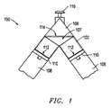
図1は、各々が本発明により光又は光波を操作又はそうでなければ伝達し、及び/又は放射圧を利用して機械的仕事を発生させるシステム及び/又は装置100の概略図である。特に、装置100は、装置100内に導入されるか、又は装置100によって操作される光波によって生じる放射線を利用する光子エンジン100である。好ましくは、本発明の光子エンジン100は、光波を受光するための1次プリズム106、1次プリズム106と作動的及び集合的に関連付けられた2次プリズム107、及び閉じ込めチャンバ102(図1の破線で示している)を含む。1次プリズム106及び2次プリズム108は、面と面で(又は、壁と壁で)当接し、圧縮境界インタフェース114を形成するように置かれる。上記に簡潔に解説したように、インタフェース114は、1つのモードにおいて、実際には2つの面の間に閉鎖可能又は圧縮可能な空気又は真空の間隙を含むことができ、これに対しては、図1a及び1bに関連してより詳しく解説する。
FIG. 1 is a schematic diagram of a system and / or
例示的光子エンジン100は、ピストンハウジング又はシリンダ108、ピストンアセンブリ110、及び反射ミラー112の実質的に同一の対を更に含む。閉じ込めチャンバ102は、2次プリズム107の前面、シリンダ108、及びミラー112によって形成される。高反射ミラー112は、可動ピストン110の平坦な表面上に装着される。ミラー112及びピストン112は、シリンダ108内を一緒に進む。下記において更に説明することになるが、ピストンアセンブリ110は、クランクシャフトアセンブリなどと機械的に接続することができる。
図1から明らかなように、反射ミラー112及びピストンアセンブリ110の移動は、閉じ込めチャンバ102の容積が、2次プリズムの少なくともいずれかの側で増大又は減少することを可能にする。好ましくは、ミラー112は、同調して移動することになる(より大きなピストン/クランクシャフトアセンブリの一部として)。更に、1次プリズム106と2次プリズム107の間の圧縮境界114は、同じく本発明による光スイッチによって制御される。上述のように、光スイッチは、空隙の閉鎖を駆動して(圧縮により)光が閉じ込めチャンバ102内へと通過することを可能にする圧電駆動機構116を用いて作動させることができる。従って、駆動機構116の作動は、制御された方式で光スイッチ114の開放及び遮断モードを決める。
As is apparent from FIG. 1, movement of the
好ましくは、光子エンジン100は、1次プリズム106及び2次プリズム107において石英材料を利用する。より具体的には、光子エンジン100は、圧電効果及び内部全反射(TIR)という石英の性質の2つの基本的な原理に基づいて作動する圧縮境界光スイッチを提供する。圧電効果は、石英が電界内に配置された時に発生する。具体的には、石英は、電界の存在の中で膨張する。石英の結晶構造は、3つの主軸X、Y、Zを有する。結晶構造のX軸に沿って方向付けられた電界を配置することにより、石英は、電界の方向に基づいて膨張又は収縮することになる。電界がX軸に沿って圧縮を生じる場合には、石英は、Y軸に沿って又はY軸において膨張することになる。膨張中にY軸に沿って石英を拘束することにより、石英内でY軸に沿って応力が発生する。X軸に沿って方向付けられた電界によるこの応力の発生、及びその結果として生じるY軸における歪みは、2つの石英(すなわち、1次プリズム106及び2次プリズム107)を圧縮するのに利用される。
Preferably, the
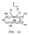
図1aは、遮断又は非作動モードにある間の圧縮境界インタフェース114の詳細図を示している。このモードでは、1次プリズム106の背面106cは、2次プリズム107の前面107cから分離している。スネルの法則及び入射角が与えられると、両方のプリズムの屈折率は、開放モードにおける光スイッチの作動を容易にするのに十分に類似である(例えば、好ましくは、互いに約5%から約20%の範囲内)。また、両方のプリズムにおける屈折率は、遮断モードにおける光スイッチの作動を容易にするのに十分に空隙(又は空間)と異なっている。その結果、空隙170が、2つの面106c、107cの間に設けられる。ここの説明では、空隙170及び面106c、107cを指す上で圧縮境界又はインタフェース114を用いる。また図1Aは、石英又は1次プリズム106の座標又は軸X、Yを示している。一般的に、空隙170は、遮断又は非作動モードで約2000ナノメートルから50ナノメートルの深さ、より好ましくは、約1000ナノメートルから100ナノメートルの間の深さを有することになる。
FIG. 1a shows a detailed view of the
図1bは、圧電駆動機構116の作動を受けた圧縮境界114の圧縮を示している。その結果、電界の印加又は励起を受けて、空隙170は、約100ナノメートル〜0ナノメートルへと圧縮される。上述のように、電界の印加は、X軸線方向の収縮を生じ、この収縮により、Y方向に応力が発生する(石英材料又は面106cがY方向に膨張することが阻止される結果として)。好ましくは、駆動機構116の適用は、1次プリズム106及び2次プリズム107の両方、又はより具体的には面106c及び107の両方に対して行われることになる。好ましくは、空隙170は、約100ナノメートル〜約0ナノメートル、より好ましくは、約50ナノメートル〜約0ナノメートルの深さへと圧縮されることになる。
FIG. 1 b shows the compression of the
更に、図1a及び1bを本発明による1次プリズム106及び/又は圧縮境界170を通じての光波AAの伝達を示すために用いる。図1aでは、光波AAは、約45°の入射角で背面106cに衝突する。空隙170によって同様に与えられる屈折率に起因して、光波AAは、TIRによって入射角に対してほぼ90°の方向に反射する。図1bでは、空隙170が実質的に排除され、2次プリズム107の石英材料が1次プリズム106のものと実質的に同様であるから、2つの面106c、107cは、ただ1つの媒体として機能する。すなわち、異なる屈折率の効果(空隙170によって与えられる)が排除される。従って、光波AAは、遮られることなく面106c及び2次プリズム107の面107cを通過する。
1a and 1b are further used to illustrate the transmission of the light wave AA through the
スネルの法則は、放射線又は電磁波が一方の媒体から他方の媒体へと通過する時の効果を説明する。その結果として生じる角度は、両方の媒体の屈折率における入射角の関数である。スネルの法則の結果が虚数であった場合には、電磁波はTIRである。本発明による光子エンジン100は、この現象を利用して、光波を1次プリズム内に閉じ込める(更に別の実施形態に関連して説明するように)。
Snell's law describes the effect of radiation or electromagnetic waves passing from one medium to the other. The resulting angle is a function of the angle of incidence at the refractive index of both media. If the result of Snell's law is an imaginary number, the electromagnetic wave is TIR. The
圧電圧縮によるTIRとTIR境界の除去とのカプリングにより、本発明による光スイッチを提供する。停止モードでは電圧が印加されず、光はTIRであり、閉じ込めチャンバ112の外側に留まる。電圧が印加された時、光スイッチは作動モードであると呼び、TIR境界は除去される。それにより、光波は、圧縮境界又はインタフェースCCを通過して閉じ込めチャンバ112内に入ることが可能になる。従って、本発明の方法の重要な段階は、光を捕捉又は閉じ込めるように、光スイッチをオンに作動して、次に迅速にオフにすることである。
The coupling of TIR by piezoelectric compression and removal of the TIR boundary provides an optical switch according to the present invention. In stop mode, no voltage is applied and the light is TIR and remains outside the
好ましくは、駆動機構116は、信号を圧電石英又はプリズム106、107に送信する高電圧、低電流(ほぼ静電的)の電源を含む。機械的接続は、例えば、1次及び2次プリズム106、107の適切な面に付着された銅板によって設けられる。駆動機構は、非常に迅速な(ギガヘルツ)パルスでの切り換えを達成するために電界効果トランジスタを更に含む。最も好ましくは、パルスは、ナノ秒で開き、次にミリ秒で停止する。
Preferably, the
図2は、ピストン210及びミラー212を含む可動アセンブリの一実施形態の概略図である。このアセンブリは、質量m(及び特定の面積)及び反射率Εによって特徴付けられる。作動時には、ミラー表面は、圧縮境界214を通じて2次プリズム207内に透過する放射線による距離dにわたる光束p1によって照射される。放射圧pは、ミラー212及びピストンアセンブリ210に対して作用する機械的力を集合的に発生させる。 FIG. 2 is a schematic diagram of one embodiment of a movable assembly that includes a piston 210 and a mirror 212. This assembly is characterized by mass m (and specific area) and reflectivity wrinkles. In operation, the mirror surface is illuminated by a light flux p 1 over a distance d due to radiation transmitted through the compression boundary 214 into the secondary prism 207. The radiation pressure p collectively generates a mechanical force acting on the mirror 212 and the piston assembly 210.
ここで図3に移ると、本発明による代替実施形態の光子エンジン300が例示されている。同様の要素を指す上で同様の参照番号を用いている図示の変形では、1次プリズム306は、2次プリズム307に隣接して位置する。特に、1次プリズム306の背面306cは、2次プリズム307の前面307cから分離され、1次プリズム306と閉じ込めチャンバ302の間に圧縮境界インタフェース314が形成される。この実施形態では、境界インタフェース314は、八角形断面のスイッチ要素を形成する。設計及び作動の全ての他の態様では、光子エンジン300は、図1に示しているものと実質的に同様である。図1の光子エンジン100と同様に、光子エンジン300は、1対のシリンダ308、その中に移動可能に収容されたピストン310、及びピストン310の上に装着された高反射ミラー312を含む。
Turning now to FIG. 3, an alternative
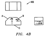
図4a及び4bは、本発明における1次プリズムとしての使用に適する様々な幾何学構成のプリズム406を示している。好ましくは、プリズム406は、1.45よりも大きい屈折率を有する結晶石英材料で作られる。実際には、光波がそこを通過するか、又はそこから反射することになる高度に研磨された表面を形成することが重要である。図4のプリズム406では、面A、B、及びCが、この目的で研磨される。
FIGS. 4a and
図5は、本発明により放射エネルギを異なる形態のエネルギ又は仕事へと変換するためのシステム501の概略図を示している。システム501は、上述のように光子エンジン500を利用する。更に、システム501は、「3M(登録商標)」の放射光膜によって覆うか又は被覆することができる内側放物表面を有する1次集光ミラー541を利用する。システム501は、少なくとも、1次集光装置541の上方に装着され、1次集光装置541の内側放物表面から反射する光波を反射するように位置決めされた2次集光装置ミラー540を更に含むか又は利用することができる。2次集光装置540は、より小さい表面によって特徴付けられるが、有利な態様においては、外面上を「3M(登録商標)」の放射光膜で覆うか又は被覆することができる。このシステムには、2次集光装置ミラー540及び1次集光装置ミラー541からの集中光を光子エンジン500に伝達するための光誘導器545を更に装備することができる。好ましくは、システム501は、スタンド及び基部アセンブリ544、並びにシステム501を放射線源に向って方向付けするための指向コントローラ543を含むことになる。
FIG. 5 shows a schematic diagram of a
図6a及び6bは、本発明の光子エンジンの変形、特に多シリンダ光子エンジン600を更に例示する概略図である。またこれらの2つの図は、本発明のエンジン600の作動も例示している。図6aは、同調して往復運動する2つのシリンダ608、608’を含むエンジン600の正面図を提供している。図6bの側立面図には、光子エンジン600の一方の側の4つのシリンダ608を示している。シリンダ608は、クランクシャフトアセンブリ611に作動的に接続したピストンアセンブリ610の進行を可能にする。
6a and 6b are schematic diagrams further illustrating a variation of the photon engine of the present invention, in particular a
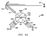
図6aに移ると、光子エンジン600は、八角形状の2次プリズム607に背面及び前面606c、607cそれぞれによって少なくとも部分的に形成された圧縮境界インタフェース614を通じて隣接して位置決めされた同様の形状の1次プリズム606を含む。2次プリズム607は、シリンダ608、608’、及び従ってシリンダ608、608’の各々内のミラー612及びピストン610と連通する。図6bの側立面図には、4つの1次プリズム606及び4つの2次プリズム607を示しており、各対は、1対又は1列のシリンダ608及びピストン610、並びにシリンダ608内に位置するクランクアセンブリ611と作動的に関連付けられる。
Turning to FIG. 6a, a
図6aに移ると、圧縮境界インタフェース614は、プリズム圧電駆動機構616によって作動的に駆動されて、上述のように圧縮境界光スイッチ(CBLS)の開放又は遮断を作動する。図6aでは、光スイッチが遮断位置にあることを示すために、614aによって表しているインタフェースを用いており(破線で)、一方で光スイッチが遮断位置にあることを表すために、参照番号614bを用いている。図6aは、光子エンジン600の外部に設けられた光波源617を更に例示している。光波617は、最初に集光装置ミラー618によって捕捉又は集中され、1次プリズム606内へと瞬間放射線として再方向付けされる(矢印AAを参照されたい)。光波AAは、背面606cに約45°の入射角で衝突する。光スイッチが遮断位置(破線及び参照番号614aによって表している)にある場合には、光波AAは、インタフェース614aで反射し(破線を参照されたい)、プリズム606の別の面を通じて再方向付けされる(そして1次プリズム606を出射する)。
Turning to FIG. 6a, the compression boundary interface 614 is operatively driven by a prism
インタフェース614が開放位置(実線及び614bによって表している)にある時には、光波AAは、インタフェース614bを通じて進み、矢印AA’によって示しているように、閉じ込めチャンバ602に入射し、背面606に衝突する。更に、プリズム606及び608は、光波AA’が閉じ込めチャンバ608内に入射し、シリンダ608内に真っ直ぐに誘導されるように構成される。すなわち、光波AA’は、好ましくは、ほぼ垂直な角度でミラー表面612に接触し、その結果、高度の反射率が得られる。例示しているように、反射光波は、開放インタフェース614bに向ってほぼ真正面に反射して戻るが、この時にインタフェースは遮断位置にあり、反射光波は、約45°の角度でインタフェースに衝突する。従って、反射光波AA’は、遮断インタフェース614bで閉じ込めチャンバ602の第2のシリンダ608の方向に反射する。上述のように、反射光波AA’は、同様にほぼ垂直の向きで第2のミラー612に衝突し、垂直の向きで反射して戻る(高度の反射率で)。従って、光波AA’は、光波AA’が第2のミラー612に達するまでに進んだ同じ経路に沿って反射する。1つの点では、所定の光路は、構成要素の中でも特にプリズム606、607、シリンダ608、608’の向きによって定められる。そのような所定の光路を図6の双方向矢印AA’で表している。
When the interface 614 is in the open position (represented by the solid line and 614b), the light wave AA travels through the interface 614b and enters the confinement chamber 602 and impinges on the
同じく前に説明したように、ミラー612の表面上の光波AA’の接触は、この表面上に放射圧を発生させる。この放射圧は、図6で「X」で表している距離だけミラー612及びピストン610アセンブリを変位させるように作用する(それによって仕事が発生する)。更に、この変位は、クランクシャフトアセンブリ611を回転させ、それによって機械的エネルギが発生する。別のモードでは、光スイッチの開放及び遮断により、光が、2次プリズム607の内側の放射線の振動数に関連する時間スケールで2次プリズム607内に入射することが可能になるように、駆動機構614は、振動数変調モードで作動させることができる。このようにして、ピストン612アセンブリ上の放射圧が強化される。
As also previously described, the contact of the light wave AA 'on the surface of the
図7の概略図は、本発明による更に別の代替実施形態の光子エンジンを示しており、同様の要素を表す上で同様の参照番号を用いている。特に、図7aは、1次プリズム706内に組み込まれた光ビーム拡大器/縮小器762を利用する1次プリズム706及び2次プリズム707の構成を示している。具体的には、光ビーム拡大器/縮小器770は、光ビームを複数回分割し、それをそれ自体の上に再方向付けし、それによって最終的に閉じ込めチャンバ702a内に導入される光波の強度を高めるように機能する。
The schematic diagram of FIG. 7 shows yet another alternative embodiment photon engine according to the present invention, wherein like reference numerals are used to indicate like elements. In particular, FIG. 7 a shows the configuration of a
図7の実施形態では、1次プリズム706aは八角形状を有し、従って、8つの面又は壁708a〜708hを有する(これらのうちの一部のみを示している)。前の実施形態と同様に、1次プリズム706は、好ましくは、石英材料で作られる。1次プリズム706は、第1の面708aから延びる突出部760を含む。好ましくは、ビーム入口760は、集中円形状を有する。更に、1次プリズム706の別の面706cは、2次プリズム708の前面707cと隣接し、そこから分離して位置決めされ、圧縮境界インタフェース714が形成される。上述のように、インタフェース714は、本発明による適正な駆動機構による作動に基づいて圧縮境界光スイッチを形成する。
In the embodiment of FIG. 7, the
図7bの詳細図を参照すると、本発明の更に別の態様では、1次プリズム706には、1次プリズム706の内部に位置決めされ、石英材料706’内に組み込まれた光ビーム拡大器/縮小器762が装備される。図7c及び7dは、拡大器/縮小器762の更に詳細な図を提供している。
Referring to the detail view of FIG. 7b, in yet another aspect of the present invention, the
図7dに戻ると、光拡大器/縮小器762は、石英材料706’内に組み込まれた切子石英ブロックである。物理的には、光拡大器/縮小器762は、中に同心空気インタフェース786が切削された石英材料706’の彫刻された円形区域である。切子石英ブロック762は、所定の直径を有する到着光ビームAA上の中心に置かれている。図7bに示しているように、石英ブロック762(すなわち、光拡大器/縮小器762)は、石英−空気インタフェースの1組の同心45°切子面を設ける。クロスハッチング区域は、1次プリズム706の石英材料706’、並びに石英ブロック762の石英材料706’’を示している。残りのクロスハッチングのない区域は、石英材料のない空気又は真空インタフェース782である。より重要なことには、これらの空気インタフェース782は、石英材料のものとは異なる光学的性質(すなわち、屈折率)を有する。図7b、及び図7cの平面図は、同様に同心インタフェースの外側円筒を形成する同心ミラー780を示している。下記に説明することになるが、ミラー780は、作動中に最外側直径同心円筒の光を反射し、それによって光路を逆転し、光縮小処理を開始するように機能する。
Returning to FIG. 7d, the light expander /
図7dの概略図には、本発明の光拡大器/縮小器762が、1次プリズム706を通じて進む光ビームAAを如何に伝達又はそうでなければ操作するかということが例示されている。伝達の第1のモードでは、光ビームAAEは、45°の石英−空気インタフェース784上で反射する。各入射ビームは、外向き方向の2回の90°反射を受け、それによってビーム直径が大きい(拡大)直径へと変換される。逆進モードでは、光ビームAACは、石英−空気インタフェース784に再度当たり、直径をより小さい(縮小)直径に変換する2つの90°反射を再度受ける。
The schematic diagram of FIG. 7d illustrates how the light expander /
従って、光拡大器/縮小器762は、光拡大、光反射、及び光縮小という3つの作動をもたらす。光反射(AAL)は、光ビームAAが最大同心円筒まで拡大された時点で発生する。この発生は、光AALの方向を逆転するミラー780の反射によって促される。光ビームが完全に拡大されて縮小された状態で、光スイッチ(圧縮境界インタフェース714)が始動され、それにより、図7gに示しているように閉じ込めチャンバ702を2つの方向に流し込むことが可能になる。図7hは、ビーム束が1次プリズム706内で増倍された後に結果として生じるミラー710及びピストンアセンブリ712に対して作用するビームパターンを示している。光の全てが閉じ込めチャンバ702内に注入されると、光スイッチは遮断位置に戻され、それがもたらすビームは、閉じ込めチャンバ702内に閉じ込められる。従って、1次プリズム706からの光ビーム束の増倍は、より高いパワー出力を生じる。
Accordingly, the light expander /
図7e及び7fは、圧縮境界光スイッチが遮断又は停止モードにある間の1次プリズム706の一般的な作動を示している。集光された光ビームAAは、ほぼ垂直の角度でビーム入口760を通じて1次プリズム706内に導入される。好ましくは、ビーム入口760は、1次プリズム706内に導入される光ビームAAが、背面706c及び圧縮境界インタフェース714の方向に誘導されるように位置する。最初に、光スイッチは、遮断又は反射段階にある。従って、光ビームAAは、ほぼ垂直の角度で1次プリズム706の別の面706eに向って反射する。この反射光ビームAAの入射角は、光ビームAAが、同様にプリズム面706e(及びその後の面706g)をほぼ垂直な角度で反射することになるようなものである。従って、図7eに例示しているように、光ビームAAは、最初に、内部全反射に起因して1次プリズム706の周囲を回転する。
FIGS. 7e and 7f show the general operation of the
好ましくは、集光されたビームAAは、1次プリズム706に入射して、ビーム拡大器/縮小器762に入射する前に3回の光反射を受ける。光ビームAAが拡大器/縮小器762に入射する方向は、ビームAAが拡大されるか又は縮小されるかを決める。図7eでは、光ビームAAは、1次プリズム706内で時計回り方向に周回するように示している。この方向では、ビーム拡大器/縮小器762内への光ビームの入射は、ビームAAが拡大される結果を生じる。逆に、光ビームAAは、1次プリズム内で反時計回り方向に向けることができる。図7fに例示しているように、光ビームAAは、結果として生じる光ビームが縮小されることになるように拡大器/縮小器762に入射する。各周回及びビーム拡大器/縮小器内への導入により、結果として生じる光ビームAAは、同心円筒の次のレベルへと拡大又は縮小する。しかし、拡大は、最大レベルの同心円筒にある反射ミラー780によって制限される。この時点で、光ビームAAの方向は逆転され、それによって縮小処理が再始動される。
Preferably, the collected beam AA enters the
付加的な本発明の特徴、及び/又は前に説明したように放射線を利用し、及び/又は光波及び放射圧を伝達するための装置及び/又は方法への改善を示すために図8〜20を提供する。例示及び便宜目的で、主に光子エンジンを背景として図及び本発明を以下に説明する(図1〜7に関して前に説明されているように)。しかし、本発明は、様々な本発明の概念のそのような特定的かつ例示的な構成及び用途に限定すべきではない。これらの様々な概念を他の構成内で、更に他の用途において採用することができることを意図しており、これは、当業者には明らかであろう。そのような他の構成及び他の用途は、本発明によって想定されている。 8-20 to illustrate additional inventive features and / or improvements to the apparatus and / or method for utilizing radiation and / or transmitting light waves and radiation pressure as previously described. I will provide a. For purposes of illustration and convenience, the figures and the present invention are described below (as previously described with respect to FIGS. 1-7), primarily in the context of a photon engine. However, the invention should not be limited to such specific and exemplary configurations and applications of various inventive concepts. It is contemplated that these various concepts can be employed in other configurations and in other applications, as will be apparent to those skilled in the art. Such other configurations and other applications are envisioned by the present invention.
例えば、本発明の装置及び方法の様々な態様は、切り換え及び光学関連用途を含む厳密な伝達作動に採用することができることを想定している。特定の用途では、光増幅、発電、及び/又は可動反射面の使用は、関連しない場合がある。例えば、これらの態様は、厳密な切り換え及び/又は制御作動では用いられない場合がある。しかし、そのような更に別の用途は、本発明による光波における放射圧の利用、及び/又は光波(又は放射圧)を伝達する段階を伴うことに注意されたい。 For example, it is envisioned that various aspects of the apparatus and method of the present invention can be employed in strict transmission operations including switching and optical related applications. In certain applications, light amplification, power generation, and / or the use of movable reflective surfaces may not be relevant. For example, these aspects may not be used in strict switching and / or control operations. It should be noted, however, that such further applications involve the use of radiation pressure in light waves and / or the transmission of light waves (or radiation pressure) according to the present invention.
図8は、本発明の好ましい実施形態に従って光ビームによって伝えられる放射圧を機械的仕事に変換するためのエンジン800(光子エンジン)の概略図である。この好ましい実施形態では、光子エンジン800は、余熱を低減するために光ビームを赤方偏移する段階を有する新しい熱制御技術を採用する。この好ましいモードは、可動ミラーにおける近全反射面(NTRS)、及びこのミラーに移動可能に関連付けられ、直列に位置決めされた複数の共振圧電アクチュエータを用いる。この実施形態では、反射面及び可動ミラーは可動プリズム内に設けられる。好ましいモードでは、機械的仕事は、電気出力への変換の前に、NTRSを通じて可動プリズム及び圧縮可能圧電アクチュエータへと移行される。好ましくは、光子エンジンの作動は、本明細書において大部分を説明してきた光ビーム集光、光ビーム増倍、及び光ビーム閉じ込めを含む他の重要な部分処理を含む。
FIG. 8 is a schematic diagram of an engine 800 (photon engine) for converting radiation pressure carried by a light beam into mechanical work in accordance with a preferred embodiment of the present invention. In this preferred embodiment, the
本発明のエンジンのある一定の構成要素又は処理の作動の背景にある原理は、支配的仕事方程式、光スイッチングに適用されるフレネルの方程式、関与媒質領域中を光が移動する間の光を定量化するための単純な減衰式、及び内部全反射を説明するスネルの法則によって説明することができる。支配的仕事方程式は、光子エンジンの仕事出力を計算するための単一の式を与える。フレネルの方程式は、エバネッセント波の超臨界角トンネル現象を用いて光スイッチングを示し、光を閉じ込めるために必要なスイッチング機構を設計するのに適用することができる。関与媒質は、石英内の光吸収の測定値を供給する。光子エンジンの複数の構成要素は、石英を通じたエネルギ輸送に依存している。スネルの法則は、光の屈折を説明し、結果として生じる屈折角が虚数になる時には、光は内部全反射される(TIR)。 The principle behind the operation of certain components or processes of the engine of the present invention is to determine the dominant work equation, Fresnel's equation applied to optical switching, and the light as it travels through the region of the medium involved. It can be explained by a simple attenuation formula for the conversion and Snell's law explaining total internal reflection. The dominant work equation gives a single formula for calculating the work output of the photon engine. Fresnel's equation shows optical switching using the supercritical angle tunneling phenomenon of evanescent waves and can be applied to design the switching mechanism necessary to confine light. The participating medium provides a measure of light absorption in quartz. Several components of the photon engine rely on energy transport through quartz. Snell's law explains the refraction of light, and when the resulting refraction angle becomes imaginary, light is totally internally reflected (TIR).
エンジンによって発生する機械的仕事Wは、光ビームと可動ミラー表面の間の運動量移行又は放射圧を関連付けるピストン−質量系の仕事方程式[1]によって説明することができる。次式は、可動ミラーの初期速度を含み、光ビームの赤方偏移が、光ビーム伸張によって相殺されることを示している。 The mechanical work W generated by the engine can be described by the piston-mass system work equation [1] relating the momentum transfer or radiation pressure between the light beam and the movable mirror surface. The following equation includes the initial velocity of the movable mirror and shows that the red shift of the light beam is offset by the light beam stretching.
ここで、p0は、初期放射圧であり、
Amは、各ミラーの面積であり、
t0は、初期ビーム衝突持続時間であり、
mは、ミラー/ピストンアセンブリの質量であり、
ρmは、ミラーの有効反射率であり、
tsは、光スイッチの有効透過率であり、
zは、運動量移行中に可能な跳ね返り時間であり、
v0は、ミラーの初期速度である。
Where p 0 is the initial radiation pressure,
Am is the area of each mirror,
t 0 is the initial beam collision duration,
m is the mass of the mirror / piston assembly;
ρ m is the effective reflectivity of the mirror,
t s is the effective transmittance of the optical switch;
z is the bounce time possible during momentum transfer,
v 0 is the initial speed of the mirror.
エンジン効率は、式(1)に示している仕事を最初の光ビーム内に含まれる全エネルギによって割算することによって計算される。 Engine efficiency is calculated by dividing the work shown in equation (1) by the total energy contained in the first light beam.
光子エンジン800は、集光装置/集光810、光増倍器又は増幅器/増幅820、光変換器/変換830、並びに発電器/発電840という4つの主な構成要素/相を有するものとして説明することができる。図8の概略図は、この4つの主な構成要素を示しており、更に所定の経路に沿ってこの構成要素の中を通る光波AAの例示的な進行を示している。
集光装置810は、大きい面積の又は大きく分散した集光光から、より小さい集中ビームAAを発生させる。この集光相では、光源は、好ましくは、大きい放物面集光装置によって捕捉される太陽光入力である。ビームは、逆放物面ミラーに合焦され、集光光AAは、再度集中ビームへと視準される。次に、この集中ビームは、光増倍器820に誘導される。光増倍器820は、ビームAAを操作して、増倍又は増幅済みビームを発生させる。この増幅相中に、集光ビームは、集光装置から連続して入力される。別の態様では、光増倍器820は、更に集光相の光変換相との同期を可能にする。その結果は、連続した光処理及びエンジン作動である。
The condensing
図8は、光増倍器820への拡張タブを有する入口を示している。入射ビームは、意図的に拡張タブに対して垂直に誘導され、それによって反射を引き起こすと考えられるブリュースター角が回避される[4]。従って、機械は、全ての入射ビームを垂直な表面に沿って石英に衝突させるように設計される。同様に、それにより、そうでなければ光を波長に基づいて分散させる(レインボー効果)と考えられる分散又は波長依存屈折が阻止される。垂直な表面に沿って入射する光は、正反射を引き起こすことになる。閉じ込めチャンバ内では、光が依然として反射されることからこの正反射は許容される。
FIG. 8 shows an inlet with an expansion tab to the
光増幅相中に、集光光ビームAAは、それ自体の周囲に巻かれ、ビームAAは、端部正面から見ると図10の1組の大きな同心円に見える。この処理は、比較的低いエネルギの肉薄のビームを取得し、各同心円によってビームを拡幅することによってビームエネルギを高める。光路AAは、増倍器820の内側で循環を続け、各順方向循環は拡大器に衝突し、次に、大きな直径の同心円へと拡大する。ビームが外側同心円に達すると、光AAは、ミラー表面上に入射し、逆方向に反射される。次に、光AAは、逆方向にあること及び反対の周回であることを除いて光増倍器820内で上記と同じ経路を戻る。光AAが光縮小器上に入射すると、ビーム直径は、各逆循環によって低減する。光増倍器820は、逆ビームが、増倍器の周りに初期ビーム直径(凝集円)へと再度繰り出された時に最大パワーのビームを発生させる。この時点で、集光光ビームAAは、増倍済み(強化済み)光ビームAAへと変換されており、両方の方向で光スイッチに当たる。
During the light amplification phase, the focused light beam AA is wrapped around itself and the beam AA appears as a set of large concentric circles in FIG. This process obtains a relatively low energy thin beam and increases the beam energy by widening the beam by each concentric circle. The optical path AA continues to circulate inside the
光変換相は、全反射モード(遮断)から全透過モード(開放)へと変化するように光スイッチを作動させることによって始動される。その結果、増倍済みビームは、光増倍器820から閉じ込めチャンバ830内に注入される。光増倍器から、対象の光ビームが完全になくなると、光スイッチは、全反射モード(遮断)に戻される。
The light conversion phase is initiated by activating the optical switch to change from total reflection mode (blocking) to total transmission mode (open). As a result, the multiplied beam is injected from the
光を閉じ込めるには、全反射から全透過に迅速に切り換える機構が必要である。この光スイッチの一実施形態を本明細書では圧縮境界光スイッチ(CBLS)と呼ぶ。このスイッチは、図11に示しているように2つの石英プリズム1101を用いる。石英プリズム1101は、小さい距離dが2つのプリズム1101の間に存在するように分離される。図11Aを参照すると、最初にこの距離は有意に大きくなり(dr)、内部全反射が達成される。図11Cを参照すると、非常に小さい距離dtしか存在しないように2つのプリズムが互いに非常に近い時に光は全透過される。図11Bを参照すると、中途の表面が互いに移動している間には、光は他方の表面に触れ、光は、透過及び反射の両方を受けることになる。透過量は、フレネルの方程式[2]を用いて多重境界問題として解くことができる。
In order to confine light, a mechanism for quickly switching from total reflection to total transmission is required. One embodiment of this optical switch is referred to herein as a compressed boundary optical switch (CBLS). This switch uses two
2つの石英プリズム1101の間の空間が十分に幅狭である時には、エバネッセント波が第2の表面を励起し、それによって光が透過される。透過量は、入射角、間隙の屈折率、石英プリズムの屈折率、光の波長、及び光の偏光の関数である。
When the space between the two
p偏光における全透過率を式(2)に示す。 Formula (2) shows the total transmittance in p-polarized light.
s偏光における全透過率を式(3)に示す。 Formula (3) shows the total transmittance in s-polarized light.
フレネル係数tp、ts、rp、及びrsは、マクスウェルの方程式の直接的な結果である。p偏光におけるこれらの係数を式(4.1〜4.4)に示している。 The Fresnel coefficients t p , t s , r p , and r s are direct results of Maxwell's equations. These coefficients for p-polarized light are shown in equations (4.1-4.4).
s偏光におけるこれらの係数を式(5.1〜5.4)に示している。 These coefficients for s-polarized light are shown in equations (5.1-5.4).
全p偏光透過率は、間隙距離及び波長の関数として解かれ(6)、その結果を図12Aにプロットしている。 The total p-polarized transmittance is solved as a function of gap distance and wavelength (6) and the result is plotted in FIG. 12A.
全s偏光透過率は、間隙距離及び波長の関数として解かれ(7)、その結果を図12Bにプロットしている。 The total s-polarized transmittance is solved as a function of gap distance and wavelength (7) and the result is plotted in FIG. 12B.
全透過及び全反射状態は、可視光スペクトル(400nm〜700nm)に対して、それぞれ、dt=0nm及びdr>1000nmで発生する。それにより、CBLSに対する最低作動基準が定められ、完全に平坦な表面でなければ、全透過率状態は、石英プリズムが互いに圧縮されることを必要とすることが示されている。 Total transmission and total reflection states occur at d t = 0 nm and d r > 1000 nm, respectively, for the visible light spectrum (400 nm to 700 nm). Thereby, a minimum operating standard for CBLS has been established and it has been shown that if not a perfectly flat surface, the total transmission state requires the quartz prisms to be compressed together.
光変換相では、光閉じ込めチャンバは、増幅済み光ビームを受光して閉じ込め、光ビームによって生じる放射圧の動力利用を容易にする。閉じ込められた増倍済みビームは、2つの近全反射面(NTRS)上に誘導される。閉じ込めチャンバは、光ビーム内に含まれるエネルギが消耗するまでNTRS上で閉じ込められた光ビームの連続反射を起こすように機能する。 In the light conversion phase, the light confinement chamber receives and confines the amplified light beam and facilitates the power utilization of the radiation pressure generated by the light beam. The confined multiplied beam is directed onto two near total reflection surfaces (NTRS). The confinement chamber functions to cause continuous reflection of the light beam confined on the NTRS until the energy contained within the light beam is depleted.
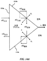
この実施形態では、可動ミラー及び反射面は、可動石英プリズム1310によって形成される。図13Aは、プリズム1310の平面図を提供しており、透過前面又は前表面1310a、及びプリズム本体1310d内に位置決めされた2つの傾斜した反射面又は反射表面13b、13cを示している。図13Bの断面図は、反射面1310b、1310cの相対位置、及びこれらの表面1310a、310bが形成する角を成すV字形状をより詳細に示している。図13Aの平面図に示しているように、反射面1310b、1310cの上部及び底部の円形稜線は、プリズム1310の前表面310aの下で一連の同心円を示している。また図13Bの断面図は、最初の反射面1310bに向かい、最初の反射面1310bから戻りの反射面1310cに行き、戻りの反射面1310cから前表面を通じてプリズム1310から離れる方向にある光ビームAAの所定の誘導経路を示している。下記でより詳細に説明することになるが、面1310a、1310b、及び1310cは、光ビームAAが、前面1310aを約90度で通過し、背面1310b、1310cの各々に約45度で衝突し、更に、再度前面を約90度で通過するように相対的に位置決めされる。その結果、光ビームAAは、望ましくは、透過前面1310aを通過し、2つの背面1310b、1310cの各々から反射する。この点から、表面又は面1310a、1310b、1310cを含むプリズム1310を近全反射面(NTRS)と呼ぶ。下記により詳しく説明するように、可動プリズム1310及びNTRSの作動は、これらと作動可能に関連付けられた一連の圧電アクチュエータと連係して有利な熱制御技術をもたらす。
In this embodiment, the movable mirror and the reflecting surface are formed by a
本発明に用いる近全反射面(NTRS)は、関与媒質がエネルギ吸収を引き起こし、赤方偏移がエネルギ発散を引き起こすにも関わらず、内部全反射を利用して繰返し反射からの損失を排除する。従って、NTRSは、市販のミラーよりも有意に優れた性能の有効ミラー表面を提供する。 The near total reflection surface (NTRS) used in the present invention uses internal total reflection to eliminate losses from repeated reflections, even though the participating medium causes energy absorption and the red shift causes energy divergence. . NTRS therefore provides an effective mirror surface with significantly better performance than commercially available mirrors.
この改善された性能を可能にする原理を説明するために、ここで図14を参照する。図14は、エネルギパケットによって表す光ビームAAのNTRS内での進行の図を提供している。初期エネルギパケットdQINITIALは、速度vで真っ直ぐに遠ざかる表面上に入射する。速度ベクトルは、初期エネルギパケットの方向ベクトルと直接に整列する。その結果として生じる入射エネルギdQINCIDENTは、式(8)のように光の速度cの関数である赤方偏移によって低減する。 To illustrate the principle that enables this improved performance, reference is now made to FIG. FIG. 14 provides a diagram of the progression of the light beam AA represented by energy packets in the NTRS. The initial energy packet dQ INITIAL is incident on the surface going straight away at the velocity v. The velocity vector aligns directly with the direction vector of the initial energy packet. The resulting incident energy dQ INCIDENT is reduced by a red shift that is a function of the speed of light c as in equation (8).
![]()
![]()
スネルの法則[4]は、結果として生じる屈折角が虚数である時に、光が内部全反射されるような光の屈折を説明する。反射エネルギdQREFLECTは、式(9)のように入射エネルギに等しい。 Snell's law [4] describes the refraction of light such that the light is totally internally reflected when the resulting refraction angle is imaginary. The reflected energy dQ REFLECT is equal to the incident energy as shown in Equation (9).
![]()
![]()
反射エネルギは、プリズムの他方の側に速度ベクトルに対して直角に接触することから赤方偏移がなく、従って、dQFINALは、式(10)のように反射エネルギに等しい。 Since the reflected energy is in contact with the other side of the prism at right angles to the velocity vector, there is no red shift, so dQ FINAL is equal to the reflected energy as in equation (10).
![]()
![]()
入射エネルギは、速度が高い程低くなるが、結果として生じる力は、ほぼ同じである。一方が低い表面速度に対するもの、及び他方が高い表面速度に対するものである2つの等しい力からの仕事出力は、同じではない。高い表面速度は、式(1)に示すように高い仕事出力を発生させることになり、これは、最終の速度(第1の二乗項)が初期速度(第2の二乗項)を基準とすることによる。ミラー表面を十分に速く移動することによって赤方偏移がミラーの反射率に接近すると、閉じ込められたエネルギは、赤方偏移によって発散することになり、それによって余熱が低下する。積層圧電アクチュエータは、共振して、機械的仕事を電気に効率的に変換し、赤方偏移に向けて高NTRS速度を得るための機構を提供する[5]。放射圧の機械的仕事への変換を起こすのに加えて、本明細書に教示するNTRSとアクチュエータの組合せは、熱制御の潜在的な技術的問題に対する技術的解決法としての役割を達成する。 The incident energy is lower at higher velocities, but the resulting force is approximately the same. The work output from two equal forces, one for low surface velocity and the other for high surface velocity, is not the same. A high surface velocity will generate a high work output as shown in equation (1), which is that the final velocity (first squared term) is relative to the initial velocity (second squared term). It depends. When the red shift approaches the reflectivity of the mirror by moving fast enough on the mirror surface, the trapped energy will be dissipated by the red shift, thereby reducing the residual heat. Multilayer piezoelectric actuators resonate and provide a mechanism for efficiently converting mechanical work to electricity and obtaining high NTRS speeds towards redshift [5]. In addition to causing the conversion of radiation pressure into mechanical work, the NTRS and actuator combination taught herein achieves a role as a technical solution to the potential technical problem of thermal control.
関与媒質は、容積を通じて放射交換を達成する。放射線がその内部を進む複数の媒体(又は単一の媒体)は、減衰を引き起こす場合がある。例えば、放射平衡にあるガスのような材料では、波長への依存性を無視することができる。これは、石英のような固体においても可能である。この簡略化により、簡単な吸収係数の使用が可能になる[3]。 The participating medium achieves radiation exchange through the volume. Multiple media (or a single medium) through which radiation travels can cause attenuation. For example, for a material such as a gas in radiation equilibrium, the dependence on wavelength can be ignored. This is also possible for solids such as quartz. This simplification allows the use of simple absorption coefficients [3].
初期エネルギパケットdQINITIALは、図示のようにこのエネルギパケットが相互作用するか又は屈折することができる領域に入射し、ここで関与媒質に遭遇する。エネルギパケットが関与媒質を通じて進むと、それは、それが媒体によって吸収される(dQABSORBED)媒体を損失する。エネルギパケットが媒体を出射すると、透過エネルギdQTRANSMITTEDは、図示のように、再度関与媒質と相互作用するか又は屈折することができる。 The initial energy packet dQ INITIAL is incident on a region where it can interact or refract as shown, where it encounters the participating medium. As the energy packet travels through the participating medium, it loses the medium it is absorbed by the medium (dQ ABSORBED ). When the energy packet exits the medium, the transmitted energy dQ TRANSMITTED can again interact or refract with the participating medium, as shown.
このエネルギパケットにおけるエネルギ収支は、式(11)のように書くことができる。 The energy balance in this energy packet can be written as equation (11).
![]()
![]()
吸収の後に残された透過エネルギは、式(12)のように吸収係数を用いて計算される。 The transmission energy left after absorption is calculated using the absorption coefficient as shown in equation (12).
![]()
![]()
吸収エネルギは、式(13)のように計算することができる。 The absorbed energy can be calculated as shown in Equation (13).
![]()
![]()
NTRS有効反射率ρNTRSは、式(14)のように計算することができる。 The NTRS effective reflectance ρ NTRS can be calculated as shown in Equation (14).
この場合には、散乱を無視することができると仮定しており、負の吸収を考慮していないことに注意されたい[3]。石英表面反射率ρQUARTZは、dQOUT内に含まれ、dQINは、石英媒体に入射する時に反射されるエネルギを収容する。 Note that in this case, scattering is assumed to be negligible and negative absorption is not considered [3]. Quartz surface reflectance [rho QUARTZ is contained within dQ OUT, dQ IN accommodates energy reflected when incident on the quartz medium.
電気発生相は、光変換器相と同時に発生する。積層共振圧電アクチュエータは、NTRSに直接取り付けられる。光変換相の継続期間にわたって、アクチュエータは縮小しており、NTRS面を入射ビームから高速度で遠ざけることによって閉じ込められた光を赤方偏移させるという必要な熱制御の利点をもたらす。更に、光によってNTRSを通じて圧電アクチュエータに印加される力からの付加的な電流は、H−ブリッジ(又は同様の)回路を用いて蓄積される。エネルギ伝達構成要素としての圧電アクチュエータの採用は、公知であることに注意すべきである。本発明の開示内容が与えられれば、本発明における圧電アクチュエータの統合は、当業者には明らかであろう。 The electricity generation phase occurs simultaneously with the light converter phase. The laminated resonant piezoelectric actuator is directly attached to the NTRS. Over the duration of the light conversion phase, the actuator shrinks, providing the necessary thermal control benefits of red shifting confined light by moving the NTRS surface away from the incident beam at high speed. Furthermore, additional current from the force applied to the piezoelectric actuator by the light through the NTRS is stored using an H-bridge (or similar) circuit. It should be noted that the use of piezoelectric actuators as energy transfer components is well known. Given the disclosure of the present invention, the integration of piezoelectric actuators in the present invention will be apparent to those skilled in the art.
ここで、本出願人は、このエンジンに対するモデル化のシステム及び方法を提供する。5つの時間的光線追跡機能を提供する。
(1)反射によって及ぼされる放射圧からの力蓄積、
(2)光スイッチングを用いて閉じ込めをモデル化する可変光学器械、
(3)ビーム増倍及び分割からの光束デルタをモデル化する封入体、
(4)赤方偏移からのエネルギ損失、
(5)関与媒質内のエネルギ吸収。
The Applicant now provides a modeling system and method for this engine. Provides five temporal ray tracing functions.
(1) force accumulation from radiation pressure exerted by reflection,
(2) A variable optical instrument that models confinement using optical switching,
(3) an enclosure that models the beam delta from beam multiplication and splitting;
(4) Energy loss from redshift,
(5) Energy absorption in the participating medium.
第1の機能は、直接の加熱成分のみからのノードへの放射圧に加えて、反射エネルギからの力を含む放射圧(又は放射力)の計算を可能にする。反射エネルギからの放射圧は、複数の反射の間の光子から可動ピストンへの内部運動量移行をモデル化することにより、作動的光子エンジンをモデル化する最も基本的な概念である。 The first function allows for the calculation of radiation pressure (or radiation force), including force from reflected energy, in addition to radiation pressure to the node from direct heating components only. Radiation pressure from reflected energy is the most basic concept of modeling an active photon engine by modeling the internal momentum transfer from photons to movable pistons during multiple reflections.
第2の機能は、時間で変化する光学性質による光閉じ込めである。この機能は、光子エンジンを光ビームの増倍を含むように拡張するのに必要である。この機能は、高反射なものとして始まる表面をモデル化し、次に、有限の時間量の後に光学性質を瞬時に変更して透過を可能にすることによって達成される。その後の有限の時間量の後に、表面は、高反射のものに瞬時に変更し戻される。第1の場合の機能とは異なり、時間依存の性質を有することにより、第3の場合に示すようにビームパワーの増倍が可能になる。 The second function is light confinement due to optical properties that change over time. This capability is necessary to expand the photon engine to include light beam multiplication. This function is achieved by modeling a surface that begins as highly reflective and then instantaneously changing the optical properties after a finite amount of time to allow transmission. After a finite amount of time thereafter, the surface is instantly changed back to highly reflective. Unlike the function in the first case, the time-dependent nature makes it possible to multiply the beam power as shown in the third case.
第3の機能は、封入体間の切り換え時の光束変化である。この機能は、長い低光束ビームがそれ自体に巻かれ、次に、可変光学器械スイッチによって分割されて短い高光束ビームが達成される時の光源における光束変化(又は光束デルタ)を計算する。この処理は、ビーム長さを実質的に圧縮し、全エネルギが同じに留まるので、その結果は、高光束ビームである。 The third function is a change in luminous flux at the time of switching between inclusion bodies. This function calculates the flux change (or flux delta) at the light source when a long low flux beam is wrapped around itself and then split by a variable optics switch to achieve a short high flux beam. This process compresses the beam length substantially and the total energy remains the same, so the result is a high flux beam.
図15及び16は、時間的光線追跡の連続図及び時間的光線追跡のフラット・ランド図を提供している。 15 and 16 provide a continuous view of temporal ray tracing and a flat land view of temporal ray tracing.
光束デルタΔFは、式(15)のように、サンプル光線数n、閉じ込め光線数m、及び異なるサンプル時間、初期サンプル範囲t0からt1、並びに可変光学器械スイッチ範囲t2からt3を考慮に入れることによって計算される。 The luminous flux delta ΔF takes into account the number of sample rays n, the number of confined rays m, and different sample times, initial sample range t 0 to t 1 , and variable optical instrument switch range t 2 to t 3 as in equation (15) Calculated by putting in
光束デルタは、式(16)のように、モデル1光束q’’1からの増倍済みビームの閉じ込めチャンバ光束q’’2を特定するのに用いることができる。 Light beam delta may be used as shown in equation (16), to identify the model first light flux q '' multiplication already beam containment chamber flux q from 1 '' 2.
![]()
![]()
第4の機能は、赤方偏移に起因するビーム強度におけるエネルギ損失である。可動ピストンへの運動量移行を有する機械では、入射ビームから遠ざかるピストンの移動は、反射エネルギの赤方偏移を引き起こすことになる。この赤方偏移は、反射中に表面が移動する速度に基づいて、単純に反射光線エネルギを低減することによってモデル化することができる。 The fourth function is energy loss in beam intensity due to redshift. In machines with momentum transfer to the movable piston, movement of the piston away from the incident beam will cause a red shift of the reflected energy. This redshift can be modeled by simply reducing the reflected light energy based on the speed at which the surface moves during reflection.
第5の機能は、関与媒質による吸収からのエネルギ損失である。この現象は、光が、石英のような固体を通じて透過される時に発生する。光子エンジン内の光路は、石英との多くの相互作用を必要とする。光増倍器内の相互作用は、石英の内部で長距離を進む光線を生じることになる。石英内で光線がより長く進む程、吸収によってより多くのエネルギが損失する。それにより、低透過率及び関与媒質の加熱が生じる。光子エンジンの最も望ましい作動は、運動量移行においてエネルギが利用可能であるように、最も低い吸収(最も高い透過)を有するものである。 The fifth function is energy loss from absorption by the participating medium. This phenomenon occurs when light is transmitted through a solid such as quartz. The optical path in the photon engine requires a lot of interaction with quartz. Interaction within the photomultiplier will result in light rays traveling a long distance inside the quartz. The longer the ray travels in quartz, the more energy is lost due to absorption. This results in low transmission and heating of the participating medium. The most desirable operation of the photon engine is to have the lowest absorption (highest transmission) so that energy is available for momentum transfer.
図17は、関与媒質をモデル化する制御容積手法を示している。関与媒質の領域を連続容積として表す代わりに、この領域を小さい制御容積へとメッシュ分割することにより、関与媒質が領域を通じて移動する時に吸収を量子化することが可能になる。図15に示しているように、2つの制御容積間のインタフェースにおけるエネルギ収支は、式(17.1〜17.2)のように内部加熱dQn、abs、及びその後の制御容積に入射するエネルギdQx+を生じる。 FIG. 17 shows a controlled volume approach for modeling the participating media. Instead of representing the region of the participating medium as a continuous volume, meshing this region into smaller control volumes allows the absorption to be quantized as the participating medium moves through the region. As shown in FIG. 15, the energy balance at the interface between the two control volumes is the internal heating dQ n, abs and the energy incident on the subsequent control volume as in equations (17.1 to 17.2). dQ x + is generated.
![]()
![]()
![]()
![]()
時間的光線追跡機能の各々を例示的作業エンジンを正確に模擬する単一シミュレーションへと組み合わせる解析を実施した。光を光線としてモデル化する時に、収差を回避するように注意すべきである。この歪曲は、光がある一定の点に合焦される時に発生する。このエンジン設計は、収差を回避している。常に内部全反射して、いかなる入射角もなしに1つの媒体から別の媒体へと表面に垂直に移行することにより、ブリュースター角も同じく回避される。 An analysis was performed that combined each of the temporal ray tracing functions into a single simulation that accurately simulated the exemplary work engine. Care should be taken to avoid aberrations when modeling light as rays. This distortion occurs when light is focused on a certain point. This engine design avoids aberrations. By always total internal reflection and transition perpendicular to the surface from one medium to another without any incident angle, the Brewster angle is also avoided.
図18は、例示的光子エンジン1800をこのエンジン1800における光線又はビーム光路を含めて示している。このエンジンは、上述のようにスイッチ1850を用いる(2つの隣接プリズム1840、1842を有する)。図19は、別のエンジン1900及びそれに関連する光線経路を示している。エンジン1900は、光スイッチ1950において単一のプリズムを用いる。これまでは第2のプリズム(例えば、1942)が、閉じ込めチャンバの一部分を形成したが、ここでは、線形スイッチ表面又は簡易に線形スイッチ1950が、圧縮境界スイッチの第2の半分を形成する。
FIG. 18 illustrates an
線形スイッチ1960は、第2のプリズムの石英材料を通じて進む光ビームの距離を実質的に短縮する(図18の設計及びそれ以前に説明した設計と比較して)。この別の設計は、三角錐区域1960aを用いる点でNTRSのものと同様である。スイッチ1960は、一連の線形三角プリズム1960aから成る。光は、面のうちの1つに垂直に入射し、光スイッチが反射性を有する時には内部全反射する(TIR)。光スイッチが透過性を有する時には、線形スイッチの平坦な表面は、1次プリズム1940に対して圧縮される。この設計は、エンジン内のあらゆるプリズムに対して拡張することができ、それによって石英の関与媒質に起因する減衰量が低減する。
The
CBLSを拡張することによってNTRS設計と同様の線形三角プリズム設計(線形スイッチ)を有するように設計を合成するシミュレーションツールを用いた。スプレッドシートを利用して、光線毎の閉じ込めチャンバ内の反射時間、ρNTRS及びtSWITCHの推定値、並びに最も低い石英の吸収係数aを用いて各設計の効率を推定した。表1に反映されているように、線形スイッチの使用により、有意に高い効率が得られる。高い効率を得る上で、更に別の技術的解決法(線形スイッチ)が実施され、技術的問題又は難問(サイズ及び製造における効率及び経済性)が解決される。 A simulation tool was used to synthesize the design to have a linear triangular prism design (linear switch) similar to the NTRS design by extending CBLS. A spreadsheet was used to estimate the efficiency of each design using the reflection time in the confinement chamber for each ray, the estimated values of ρ NTRS and t SWITCH , and the lowest absorption coefficient a of quartz. As reflected in Table 1, the use of a linear switch provides significantly higher efficiency. In order to obtain high efficiency, yet another technical solution (linear switch) is implemented to solve technical problems or challenges (size and efficiency in manufacturing and economy).
(表1)
しかし、本発明の装置の構成要素の本発明による様々な構成及び配備は、特定の環境及び用途に従って行うことができ、これらに従って変化することになることを理解すべきである。これらの変化にも関わらず、あらゆるそのような用途において、上述のように、本発明の様々な態様が適用可能になる。例えば、閉じ込めチャンバ設計、光学切り換えデバイス、並びに光増倍器又は光波増幅器のような本明細書に説明した装置の様々な態様は、他のエンジンを含む他の機械的デバイスと併合することができる。更に別の例として、ピストン及びシリンダアセンブリは、エネルギ蓄積デバイス(例えば、バネデバイス)のような別のエネルギシステムによって置換することができる。更に、説明した本発明の様々な態様は、他の構成要素なしに他の用途に用いることができる。例えば、光スイッチとNTRSミラー(可動又は非可動)との組合せは、切り換え、伝達、又は制御作動において用いることができる(本明細書に説明した光子エンジン、エンジン構成要素、又は他の構成要素とは独立して)。他の例は、同様の切り換え、伝達、又は制御用途における光増幅器又は増倍器、及び/又は光スイッチの採用を含む。 However, it is to be understood that various configurations and deployments according to the present invention of the components of the present apparatus can be made and will vary according to the particular environment and application. Despite these changes, the various aspects of the present invention can be applied in any such application, as described above. For example, various aspects of the apparatus described herein, such as confinement chamber designs, optical switching devices, and photomultipliers or lightwave amplifiers can be merged with other mechanical devices, including other engines. . As yet another example, the piston and cylinder assembly can be replaced by another energy system, such as an energy storage device (eg, a spring device). Furthermore, the various aspects of the invention described can be used for other applications without other components. For example, a combination of optical switch and NTRS mirror (movable or non-movable) can be used in switching, transmission, or control operations (with photon engines, engine components, or other components described herein) Is independent). Other examples include the use of optical amplifiers or multipliers and / or optical switches in similar switching, transmission, or control applications.
本発明の上述の説明は、例示及び説明目的で提供したものである。この説明は、本発明を本明細書に開示している装置及び方法に限定するように想定されているものではないことには注意されるものとする。上述の本発明の様々な態様は、放射圧を伝達するための他の種類のエンジン及び機械的仕事デバイス並びに方法に適用可能と考えられる。本発明はまた、上述の方法、これらの方法に利用される装置、並びに関連する構成要素及びサブシステムにおいて実施されることには注意すれるものとする。本発明のこれらの変形は、本発明の開示が与えられることにより、光学、エンジン技術、又は他の関連技術における技術者には明らかになるであろう。その結果、上述の教示及び技術、並びに関連技術の知識と同等の変形及び修正は、本発明の範囲内である。更に、本明細書に説明及び例示した実施形態は、本発明を実施する最良のモードを説明し、当業者が、本発明及び他の実施形態を利用し、更に本発明の特定の用途又は使用によって必要とされる様々な修正を加えて利用することを可能にすることを意図したものである。 The foregoing description of the present invention has been presented for purposes of illustration and description. It should be noted that this description is not intended to limit the invention to the apparatus and methods disclosed herein. The various aspects of the invention described above are believed to be applicable to other types of engines and mechanical work devices and methods for transmitting radiation pressure. It should be noted that the present invention is also implemented in the above-described methods, devices utilized in these methods, and related components and subsystems. These variations of the present invention will become apparent to those skilled in the art of optics, engine technology, or other related art given the disclosure of the present invention. As a result, variations and modifications equivalent to the above teachings and techniques, as well as knowledge of the related art, are within the scope of the invention. Furthermore, the embodiments described and illustrated herein describe the best mode of carrying out the invention, and those skilled in the art will make use of the invention and other embodiments, and will also have specific uses or uses for the invention. It is intended to be able to be used with various modifications required by.
100 光子エンジン
106 1次プリズム
107 2次プリズム
114 圧縮境界インタフェース
100
Claims (9)
(1)前記閉じ込めチャンバ内で複数の反射ミラー又は複数の反射プリズムに繰り返し衝突する光によって及ぼされる放射圧からの力の蓄積をモデル化する段階、
(2)可変光学系を含む表面を含む前記圧縮境界光スイッチを含む光子エンジンの前記閉じ込めチャンバにおける光の閉じ込めをモデル化する段階、
(3)前記光が前記光子エンジンを通過する時に該光を増倍させかつ分割することから生じる光束デルタをモデル化する段階、
(4)前記複数の反射ミラー又は複数の反射プリズムのうちの少なくとも一つを十分に高い速度で移動させて前記処理された光を赤方偏移させることによる、前記光子エンジンにおけるエネルギの損失をモデル化する段階、
(5)前記光子エンジンの関与媒体内のエネルギ吸収をモデル化する段階、及び
(6)以上の(1)から(5)を考慮して前記光子エンジンによって発生された全仕事を計算する段階、
を含むことを特徴とする方法。 A primary prism (706) that passes through the light expander / contractor (762) and the primary prism (706) and is adjacent to the surface (707c) of the secondary prism (707) and spaced therefrom by a certain distance. An initial optical path extending to the compression boundary optical switch (714) including the second surface (706c), and one or more near total reflection surfaces (NTRS) from the surface (707c) of the secondary prism (707). A method of modeling the operation of a photon engine comprising a confinement chamber having a reflective optical path extending to a plurality of reflective mirrors or a plurality of reflective prisms that are movably mounted , comprising:
(1) the step of modeling the accumulation of force from the radiation pressure exerted by said containment light repeatedly collide with the plurality of reflecting mirrors or reflecting prisms in the chamber,
(2) the step of modeling the confinement of light in the containment chamber of a photon engine including the compression boundary light switch including a surface comprising a variable optical system,
(3) modeling a luminous flux delta resulting from multiplying and splitting the light as it passes through the photon engine;
(4) the due plurality of the light the processing is moved at a sufficiently high rate at least one of the reflecting mirrors or reflecting prisms to be red-shifted, the energy loss of the said photon engine Modeling stage,
(5) modeling energy absorption in the participating medium of the photon engine, and (6) calculating the total work generated by the photon engine taking into account the above (1) to (5),
A method comprising the steps of:
可変光学系を有する前記表面が最初は高度に反射性の表面であると仮定する段階と、
前記表面が第1の有限量の時間の後に透過インタフェースに変わると仮定する段階と、 前記表面がその後の有限量の時間の後に前記高度に反射性の表面に再度変わると仮定する段階と、
を含む、
ことを特徴とする請求項1に記載の方法。 (2)
Assuming that the surface with variable optics is initially a highly reflective surface;
Assuming that the surface changes to a transmissive interface after a first finite amount of time; assuming that the surface changes back to the highly reflective surface after a finite amount of time thereafter;
including,
The method according to claim 1.
前記透過インタフェースが光の全透過をもたらすと仮定する段階と、
を更に含むことを特徴とする請求項2に記載の方法。 Assuming that the highly reflective surface does not provide light transmission;
Assuming that the transmissive interface provides total transmission of light;
The method of claim 2, further comprising:
nは、初期サンプル光線の数であり、
mは、前記閉じ込めチャンバに閉じ込められた光線の数であり、
異なるサンプル時間が、
t0からt1の初期サンプル範囲、及び
t2からt3の可変光学系切り換え範囲、
である、
ことを特徴とする請求項1から請求項5のいずれか1項に記載の方法。 (3) is the following calculation:
n is the number of initial sample rays,
m is the number of rays confined in the confinement chamber;
Different sample times,
initial sample range from t 0 to t 1 , and variable optical system switching range from t 2 to t 3 ,
Is,
The method as claimed in any one of claims 5, characterized in that.
前記光が通過することになる関与媒体を複数のより小さい制御容積に分割する段階と、 前記より小さい制御容積に対する予想エネルギ吸収を定量化する段階と、
前記より小さい制御容積の前記予想エネルギ吸収を追加することにより、前記関与媒体の容積によるエネルギ吸収をモデル化する段階と、
を含む、
ことを特徴とする請求項1から請求項7のいずれか1項に記載の方法。 (5)
Dividing the participating medium through which the light will pass into a plurality of smaller control volumes; quantifying expected energy absorption for the smaller control volumes;
Modeling energy absorption by the volume of the participating medium by adding the expected energy absorption of the smaller control volume;
including,
The method according to any one of claims 1 to 7, characterized in that:
lが、前記より小さい制御容積まで前記関与媒体を通って進む長さであり、
tnが、前記より小さい制御容積の厚みであり、
αが、真の吸収計数である、
場合に、次式:
次式:
を更に含むことを特徴とする請求項8に記載の方法。 dQ x + is the energy that enters the next smaller control volume next,
l is the length to travel through the participating medium to the smaller control volume;
t n is the thickness of the smaller control volume,
α is the true absorption coefficient,
If the following formula:
The following formula:
The method of claim 8 further comprising:
Applications Claiming Priority (3)
| Application Number | Priority Date | Filing Date | Title |
|---|---|---|---|
| US83333606P | 2006-07-26 | 2006-07-26 | |
| US60/833,336 | 2006-07-26 | ||
| PCT/US2007/016884 WO2008013930A2 (en) | 2006-07-26 | 2007-07-26 | Method and apparatus for communicating radiation pressure provided by a light wave |
Related Child Applications (1)
| Application Number | Title | Priority Date | Filing Date |
|---|---|---|---|
| JP2013124073A Division JP5745575B2 (en) | 2006-07-26 | 2013-06-12 | Method and apparatus for transmitting radiation pressure caused by light waves |
Publications (3)
| Publication Number | Publication Date |
|---|---|
| JP2009545008A JP2009545008A (en) | 2009-12-17 |
| JP2009545008A5 JP2009545008A5 (en) | 2011-12-01 |
| JP5484904B2 true JP5484904B2 (en) | 2014-05-07 |
Family
ID=38982094
Family Applications (2)
| Application Number | Title | Priority Date | Filing Date |
|---|---|---|---|
| JP2009521849A Active JP5484904B2 (en) | 2006-07-26 | 2007-07-26 | Method and apparatus for transmitting radiation pressure caused by light waves |
| JP2013124073A Active JP5745575B2 (en) | 2006-07-26 | 2013-06-12 | Method and apparatus for transmitting radiation pressure caused by light waves |
Family Applications After (1)
| Application Number | Title | Priority Date | Filing Date |
|---|---|---|---|
| JP2013124073A Active JP5745575B2 (en) | 2006-07-26 | 2013-06-12 | Method and apparatus for transmitting radiation pressure caused by light waves |
Country Status (6)
| Country | Link |
|---|---|
| US (2) | US20110096384A1 (en) |
| EP (3) | EP2642504B1 (en) |
| JP (2) | JP5484904B2 (en) |
| CN (2) | CN102495462B (en) |
| ES (1) | ES2828673T3 (en) |
| WO (1) | WO2008013930A2 (en) |
Families Citing this family (3)
| Publication number | Priority date | Publication date | Assignee | Title |
|---|---|---|---|---|
| US20040256539A1 (en) * | 2002-03-19 | 2004-12-23 | Clay Joseph M. | Method and apparatus for converting or otherwise utilizing radiation pressure to generate mechanical work |
| US20140034848A1 (en) * | 2012-08-03 | 2014-02-06 | Brian Campbell | Photon turbine generator for power generation |
| US11709747B2 (en) | 2016-01-08 | 2023-07-25 | Zoll Medical Corporation | Patient assurance system and method |
Family Cites Families (25)
| Publication number | Priority date | Publication date | Assignee | Title |
|---|---|---|---|---|
| US2997922A (en) * | 1958-04-24 | 1961-08-29 | Edward K Kaprelian | Light valve |
| BE633759A (en) * | 1962-06-20 | 1900-01-01 | ||
| US4120565A (en) * | 1977-06-16 | 1978-10-17 | The United States Of America As Represented By The United States Department Of Energy | Prisms with total internal reflection as solar reflectors |
| JPS5427445A (en) * | 1977-08-03 | 1979-03-01 | Fujitsu Ltd | Variable photo branching and coupling circuit |
| JPS5753721A (en) * | 1980-09-17 | 1982-03-30 | Matsushita Electric Ind Co Ltd | Optical actuator |
| FR2501828B1 (en) * | 1981-03-16 | 1986-03-07 | Cibie Projecteurs | IMPROVEMENTS ON MOTOR VEHICLE LIGHTS |
| US4420836A (en) * | 1981-06-05 | 1983-12-13 | The United States Of America As Represented By The Administrator Of The National Aeronautics And Space Administration | Laser resonator |
| JPS61232412A (en) * | 1985-04-08 | 1986-10-16 | Matsushita Electric Ind Co Ltd | Optical switch |
| CA1279783C (en) * | 1985-11-21 | 1991-02-05 | Minnesota Mining And Manufacturing Company | Totally internally reflecting thin, flexible film |
| JPH02211385A (en) * | 1989-02-08 | 1990-08-22 | Hamamatsu Photonics Kk | Optical energy piston engine |
| JP2771319B2 (en) * | 1990-09-19 | 1998-07-02 | 株式会社竹中工務店 | Mechanical small displacement element |
| JP3413495B2 (en) * | 1992-05-14 | 2003-06-03 | キヤノン株式会社 | Drives for micromachines |
| JPH06222212A (en) * | 1992-12-03 | 1994-08-12 | Matsushita Electric Ind Co Ltd | Polarization surface rotating optical device, polarization transformation optical device, and projection type display device |
| JPH06233568A (en) * | 1993-01-29 | 1994-08-19 | Nippon Telegr & Teleph Corp <Ntt> | Optical actuator |
| US5455709A (en) * | 1993-03-23 | 1995-10-03 | Martin Marietta Corporation | Total internal reflection spatial light modulation apparatus and method of fabrication thereof |
| US5757491A (en) * | 1996-08-19 | 1998-05-26 | The Hong Kong University Of Science & Technology | Laser interferometer system for straightness measurements |
| US5933555A (en) * | 1997-05-01 | 1999-08-03 | Alliance Fiber Optics Products, Inc. | Optical recirculation depolarizer and method of depolarizing light |
| US6226990B1 (en) * | 2000-02-11 | 2001-05-08 | Fantom Technologies Inc. | Heat engine |
| US6356390B1 (en) * | 2000-06-22 | 2002-03-12 | Thomson Licensing, S.A. | Light valve light source |
| JP2002372605A (en) * | 2001-06-15 | 2002-12-26 | Fuji Photo Film Co Ltd | Optical element and display body using the same |
| CN1337584A (en) * | 2001-09-07 | 2002-02-27 | 上海上诠光纤通信设备有限公司 | Mechenical-optical switch |
| US20040003584A1 (en) * | 2002-03-19 | 2004-01-08 | Clay Joseph Michael | Method and apparatus for converting or otherwise utilizing radiation pressure to generate mechanical work |
| US20040256539A1 (en) * | 2002-03-19 | 2004-12-23 | Clay Joseph M. | Method and apparatus for converting or otherwise utilizing radiation pressure to generate mechanical work |
| US7074463B2 (en) * | 2003-09-12 | 2006-07-11 | 3M Innovative Properties Company | Durable optical element |
| CN1295559C (en) * | 2004-11-17 | 2007-01-17 | 中国科学院上海光学精密机械研究所 | Ultrashort chirp pulse photon crystal optical parameter amplifying device |
-
2007
- 2007-07-26 CN CN201110340446.5A patent/CN102495462B/en active Active
- 2007-07-26 EP EP13160699.8A patent/EP2642504B1/en active Active
- 2007-07-26 WO PCT/US2007/016884 patent/WO2008013930A2/en active Application Filing
- 2007-07-26 EP EP18182986.2A patent/EP3410460B1/en active Active
- 2007-07-26 US US12/309,664 patent/US20110096384A1/en not_active Abandoned
- 2007-07-26 JP JP2009521849A patent/JP5484904B2/en active Active
- 2007-07-26 EP EP07836281A patent/EP2070101A4/en not_active Withdrawn
- 2007-07-26 ES ES18182986T patent/ES2828673T3/en active Active
- 2007-07-26 CN CNA2007800353124A patent/CN101568985A/en active Pending
-
2013
- 2013-06-12 JP JP2013124073A patent/JP5745575B2/en active Active
-
2020
- 2020-03-13 US US16/818,722 patent/US20200355856A1/en active Pending
Also Published As
| Publication number | Publication date |
|---|---|
| CN102495462A (en) | 2012-06-13 |
| EP3410460B1 (en) | 2020-09-02 |
| EP2642504B1 (en) | 2019-03-27 |
| JP5745575B2 (en) | 2015-07-08 |
| EP3410460A1 (en) | 2018-12-05 |
| EP2642504A2 (en) | 2013-09-25 |
| JP2013231981A (en) | 2013-11-14 |
| ES2828673T3 (en) | 2021-05-27 |
| EP2070101A4 (en) | 2012-01-25 |
| CN102495462B (en) | 2016-02-17 |
| WO2008013930A2 (en) | 2008-01-31 |
| US20110096384A1 (en) | 2011-04-28 |
| CN101568985A (en) | 2009-10-28 |
| EP2070101A2 (en) | 2009-06-17 |
| US20200355856A1 (en) | 2020-11-12 |
| WO2008013930A3 (en) | 2008-10-09 |
| JP2009545008A (en) | 2009-12-17 |
| EP2642504A3 (en) | 2014-04-23 |
Similar Documents
| Publication | Publication Date | Title |
|---|---|---|
| US20200355856A1 (en) | Apparatus for communicating radiation pressure provided by photons | |
| Horng et al. | Tunable optical switch using magnetic fluids | |
| JP5628273B2 (en) | Method and apparatus for generating mechanical work by converting or otherwise using radiation pressure | |
| US20100294921A1 (en) | Method and apparatus for converting or otherwise utilizing radiation pressure to generate mechanical work | |
| Torchigin et al. | Magnitude of the photon momentum in matter | |
| JP2009545008A5 (en) | ||
| US20220035148A1 (en) | Light Expander/Contractor Device and Method of Using Same | |
| RU218305U1 (en) | Device for focusing radiation into a curved region in the form of an acoustic hook | |
| CN114235151A (en) | Vortex light mode detection method and system based on nonparaxial coordinate transformation | |
| Lamy et al. | Scattering forces | |
| Nordin et al. | Stratified waveguide grating coupler for normal fiber incidence | |
| Feng et al. | Designing diffractive optical elements for special functions using a rigorous method |
Legal Events
| Date | Code | Title | Description |
|---|---|---|---|
| A621 | Written request for application examination |
Free format text: JAPANESE INTERMEDIATE CODE: A621 Effective date: 20100723 |
|
| A521 | Request for written amendment filed |
Free format text: JAPANESE INTERMEDIATE CODE: A523 Effective date: 20111012 |
|
| A977 | Report on retrieval |
Free format text: JAPANESE INTERMEDIATE CODE: A971007 Effective date: 20120523 |
|
| A131 | Notification of reasons for refusal |
Free format text: JAPANESE INTERMEDIATE CODE: A131 Effective date: 20120528 |
|
| A601 | Written request for extension of time |
Free format text: JAPANESE INTERMEDIATE CODE: A601 Effective date: 20120828 |
|
| A602 | Written permission of extension of time |
Free format text: JAPANESE INTERMEDIATE CODE: A602 Effective date: 20120904 |
|
| A02 | Decision of refusal |
Free format text: JAPANESE INTERMEDIATE CODE: A02 Effective date: 20130212 |
|
| A521 | Request for written amendment filed |
Free format text: JAPANESE INTERMEDIATE CODE: A523 Effective date: 20130612 |
|
| A521 | Request for written amendment filed |
Free format text: JAPANESE INTERMEDIATE CODE: A523 Effective date: 20130726 |
|
| A911 | Transfer to examiner for re-examination before appeal (zenchi) |
Free format text: JAPANESE INTERMEDIATE CODE: A911 Effective date: 20130731 |
|
| A131 | Notification of reasons for refusal |
Free format text: JAPANESE INTERMEDIATE CODE: A131 Effective date: 20130917 |
|
| A521 | Request for written amendment filed |
Free format text: JAPANESE INTERMEDIATE CODE: A523 Effective date: 20131213 |
|
| TRDD | Decision of grant or rejection written | ||
| A01 | Written decision to grant a patent or to grant a registration (utility model) |
Free format text: JAPANESE INTERMEDIATE CODE: A01 Effective date: 20140120 |
|
| A61 | First payment of annual fees (during grant procedure) |
Free format text: JAPANESE INTERMEDIATE CODE: A61 Effective date: 20140219 |
|
| R150 | Certificate of patent or registration of utility model |
Ref document number: 5484904 Country of ref document: JP Free format text: JAPANESE INTERMEDIATE CODE: R150 |
|
| R250 | Receipt of annual fees |
Free format text: JAPANESE INTERMEDIATE CODE: R250 |
|
| R250 | Receipt of annual fees |
Free format text: JAPANESE INTERMEDIATE CODE: R250 |
|
| R250 | Receipt of annual fees |
Free format text: JAPANESE INTERMEDIATE CODE: R250 |
|
| R250 | Receipt of annual fees |
Free format text: JAPANESE INTERMEDIATE CODE: R250 |
|
| R250 | Receipt of annual fees |
Free format text: JAPANESE INTERMEDIATE CODE: R250 |
|
| R250 | Receipt of annual fees |
Free format text: JAPANESE INTERMEDIATE CODE: R250 |
|
| R250 | Receipt of annual fees |
Free format text: JAPANESE INTERMEDIATE CODE: R250 |
|
| R250 | Receipt of annual fees |
Free format text: JAPANESE INTERMEDIATE CODE: R250 |