JP5484845B2 - Electric vehicle - Google Patents
Electric vehicle Download PDFInfo
- Publication number
- JP5484845B2 JP5484845B2 JP2009219761A JP2009219761A JP5484845B2 JP 5484845 B2 JP5484845 B2 JP 5484845B2 JP 2009219761 A JP2009219761 A JP 2009219761A JP 2009219761 A JP2009219761 A JP 2009219761A JP 5484845 B2 JP5484845 B2 JP 5484845B2
- Authority
- JP
- Japan
- Prior art keywords
- value
- command
- electric vehicle
- center
- wheel
- Prior art date
- Legal status (The legal status is an assumption and is not a legal conclusion. Google has not performed a legal analysis and makes no representation as to the accuracy of the status listed.)
- Expired - Fee Related
Links
- 230000001133 acceleration Effects 0.000 claims description 87
- 239000000758 substrate Substances 0.000 claims description 23
- 238000001514 detection method Methods 0.000 claims description 13
- 238000013519 translation Methods 0.000 claims description 12
- 238000012545 processing Methods 0.000 description 96
- 238000000034 method Methods 0.000 description 52
- 230000008569 process Effects 0.000 description 51
- 230000005484 gravity Effects 0.000 description 50
- 230000033001 locomotion Effects 0.000 description 47
- 230000014509 gene expression Effects 0.000 description 22
- 238000006243 chemical reaction Methods 0.000 description 10
- 230000002093 peripheral effect Effects 0.000 description 10
- 238000005259 measurement Methods 0.000 description 9
- 230000008859 change Effects 0.000 description 8
- 238000010586 diagram Methods 0.000 description 8
- 238000012937 correction Methods 0.000 description 7
- 238000013459 approach Methods 0.000 description 6
- 230000007246 mechanism Effects 0.000 description 6
- 230000005540 biological transmission Effects 0.000 description 3
- 230000007423 decrease Effects 0.000 description 3
- 125000002066 L-histidyl group Chemical group [H]N1C([H])=NC(C([H])([H])[C@](C(=O)[*])([H])N([H])[H])=C1[H] 0.000 description 2
- 239000003638 chemical reducing agent Substances 0.000 description 2
- 230000001141 propulsive effect Effects 0.000 description 2
- 230000004044 response Effects 0.000 description 2
- 238000012546 transfer Methods 0.000 description 2
- 210000001217 buttock Anatomy 0.000 description 1
- 239000003990 capacitor Substances 0.000 description 1
- 230000003247 decreasing effect Effects 0.000 description 1
- 238000013461 design Methods 0.000 description 1
- 230000005489 elastic deformation Effects 0.000 description 1
- 239000013013 elastic material Substances 0.000 description 1
- 230000009467 reduction Effects 0.000 description 1
- 230000002441 reversible effect Effects 0.000 description 1
- 230000035945 sensitivity Effects 0.000 description 1
- 230000002123 temporal effect Effects 0.000 description 1
- 210000000689 upper leg Anatomy 0.000 description 1
Images


Classifications
-
- B—PERFORMING OPERATIONS; TRANSPORTING
- B60—VEHICLES IN GENERAL
- B60L—PROPULSION OF ELECTRICALLY-PROPELLED VEHICLES; SUPPLYING ELECTRIC POWER FOR AUXILIARY EQUIPMENT OF ELECTRICALLY-PROPELLED VEHICLES; ELECTRODYNAMIC BRAKE SYSTEMS FOR VEHICLES IN GENERAL; MAGNETIC SUSPENSION OR LEVITATION FOR VEHICLES; MONITORING OPERATING VARIABLES OF ELECTRICALLY-PROPELLED VEHICLES; ELECTRIC SAFETY DEVICES FOR ELECTRICALLY-PROPELLED VEHICLES
- B60L15/00—Methods, circuits, or devices for controlling the traction-motor speed of electrically-propelled vehicles
- B60L15/20—Methods, circuits, or devices for controlling the traction-motor speed of electrically-propelled vehicles for control of the vehicle or its driving motor to achieve a desired performance, e.g. speed, torque, programmed variation of speed
-
- B—PERFORMING OPERATIONS; TRANSPORTING
- B62—LAND VEHICLES FOR TRAVELLING OTHERWISE THAN ON RAILS
- B62K—CYCLES; CYCLE FRAMES; CYCLE STEERING DEVICES; RIDER-OPERATED TERMINAL CONTROLS SPECIALLY ADAPTED FOR CYCLES; CYCLE AXLE SUSPENSIONS; CYCLE SIDE-CARS, FORECARS, OR THE LIKE
- B62K11/00—Motorcycles, engine-assisted cycles or motor scooters with one or two wheels
- B62K11/02—Frames
- B62K11/04—Frames characterised by the engine being between front and rear wheels
- B62K11/06—Frames characterised by the engine being between front and rear wheels the frame being of single-beam type
-
- B—PERFORMING OPERATIONS; TRANSPORTING
- B62—LAND VEHICLES FOR TRAVELLING OTHERWISE THAN ON RAILS
- B62K—CYCLES; CYCLE FRAMES; CYCLE STEERING DEVICES; RIDER-OPERATED TERMINAL CONTROLS SPECIALLY ADAPTED FOR CYCLES; CYCLE AXLE SUSPENSIONS; CYCLE SIDE-CARS, FORECARS, OR THE LIKE
- B62K11/00—Motorcycles, engine-assisted cycles or motor scooters with one or two wheels
- B62K11/02—Frames
- B62K11/10—Frames characterised by the engine being over or beside driven rear wheel
-
- B—PERFORMING OPERATIONS; TRANSPORTING
- B60—VEHICLES IN GENERAL
- B60L—PROPULSION OF ELECTRICALLY-PROPELLED VEHICLES; SUPPLYING ELECTRIC POWER FOR AUXILIARY EQUIPMENT OF ELECTRICALLY-PROPELLED VEHICLES; ELECTRODYNAMIC BRAKE SYSTEMS FOR VEHICLES IN GENERAL; MAGNETIC SUSPENSION OR LEVITATION FOR VEHICLES; MONITORING OPERATING VARIABLES OF ELECTRICALLY-PROPELLED VEHICLES; ELECTRIC SAFETY DEVICES FOR ELECTRICALLY-PROPELLED VEHICLES
- B60L2200/00—Type of vehicles
- B60L2200/12—Bikes
-
- B—PERFORMING OPERATIONS; TRANSPORTING
- B60—VEHICLES IN GENERAL
- B60L—PROPULSION OF ELECTRICALLY-PROPELLED VEHICLES; SUPPLYING ELECTRIC POWER FOR AUXILIARY EQUIPMENT OF ELECTRICALLY-PROPELLED VEHICLES; ELECTRODYNAMIC BRAKE SYSTEMS FOR VEHICLES IN GENERAL; MAGNETIC SUSPENSION OR LEVITATION FOR VEHICLES; MONITORING OPERATING VARIABLES OF ELECTRICALLY-PROPELLED VEHICLES; ELECTRIC SAFETY DEVICES FOR ELECTRICALLY-PROPELLED VEHICLES
- B60L2200/00—Type of vehicles
- B60L2200/22—Microcars, e.g. golf cars
-
- B—PERFORMING OPERATIONS; TRANSPORTING
- B60—VEHICLES IN GENERAL
- B60L—PROPULSION OF ELECTRICALLY-PROPELLED VEHICLES; SUPPLYING ELECTRIC POWER FOR AUXILIARY EQUIPMENT OF ELECTRICALLY-PROPELLED VEHICLES; ELECTRODYNAMIC BRAKE SYSTEMS FOR VEHICLES IN GENERAL; MAGNETIC SUSPENSION OR LEVITATION FOR VEHICLES; MONITORING OPERATING VARIABLES OF ELECTRICALLY-PROPELLED VEHICLES; ELECTRIC SAFETY DEVICES FOR ELECTRICALLY-PROPELLED VEHICLES
- B60L2200/00—Type of vehicles
- B60L2200/34—Wheel chairs
-
- B—PERFORMING OPERATIONS; TRANSPORTING
- B60—VEHICLES IN GENERAL
- B60L—PROPULSION OF ELECTRICALLY-PROPELLED VEHICLES; SUPPLYING ELECTRIC POWER FOR AUXILIARY EQUIPMENT OF ELECTRICALLY-PROPELLED VEHICLES; ELECTRODYNAMIC BRAKE SYSTEMS FOR VEHICLES IN GENERAL; MAGNETIC SUSPENSION OR LEVITATION FOR VEHICLES; MONITORING OPERATING VARIABLES OF ELECTRICALLY-PROPELLED VEHICLES; ELECTRIC SAFETY DEVICES FOR ELECTRICALLY-PROPELLED VEHICLES
- B60L2260/00—Operating Modes
- B60L2260/20—Drive modes; Transition between modes
- B60L2260/34—Stabilising upright position of vehicles, e.g. of single axle vehicles
-
- B—PERFORMING OPERATIONS; TRANSPORTING
- B62—LAND VEHICLES FOR TRAVELLING OTHERWISE THAN ON RAILS
- B62K—CYCLES; CYCLE FRAMES; CYCLE STEERING DEVICES; RIDER-OPERATED TERMINAL CONTROLS SPECIALLY ADAPTED FOR CYCLES; CYCLE AXLE SUSPENSIONS; CYCLE SIDE-CARS, FORECARS, OR THE LIKE
- B62K2204/00—Adaptations for driving cycles by electric motor
-
- Y—GENERAL TAGGING OF NEW TECHNOLOGICAL DEVELOPMENTS; GENERAL TAGGING OF CROSS-SECTIONAL TECHNOLOGIES SPANNING OVER SEVERAL SECTIONS OF THE IPC; TECHNICAL SUBJECTS COVERED BY FORMER USPC CROSS-REFERENCE ART COLLECTIONS [XRACs] AND DIGESTS
- Y02—TECHNOLOGIES OR APPLICATIONS FOR MITIGATION OR ADAPTATION AGAINST CLIMATE CHANGE
- Y02T—CLIMATE CHANGE MITIGATION TECHNOLOGIES RELATED TO TRANSPORTATION
- Y02T10/00—Road transport of goods or passengers
- Y02T10/60—Other road transportation technologies with climate change mitigation effect
- Y02T10/64—Electric machine technologies in electromobility
-
- Y—GENERAL TAGGING OF NEW TECHNOLOGICAL DEVELOPMENTS; GENERAL TAGGING OF CROSS-SECTIONAL TECHNOLOGIES SPANNING OVER SEVERAL SECTIONS OF THE IPC; TECHNICAL SUBJECTS COVERED BY FORMER USPC CROSS-REFERENCE ART COLLECTIONS [XRACs] AND DIGESTS
- Y02—TECHNOLOGIES OR APPLICATIONS FOR MITIGATION OR ADAPTATION AGAINST CLIMATE CHANGE
- Y02T—CLIMATE CHANGE MITIGATION TECHNOLOGIES RELATED TO TRANSPORTATION
- Y02T10/00—Road transport of goods or passengers
- Y02T10/60—Other road transportation technologies with climate change mitigation effect
- Y02T10/72—Electric energy management in electromobility
Landscapes
- Engineering & Computer Science (AREA)
- Mechanical Engineering (AREA)
- Power Engineering (AREA)
- Transportation (AREA)
- Motorcycle And Bicycle Frame (AREA)
- Automatic Cycles, And Cycles In General (AREA)
Description
本発明は、電動車両に関するものである。 The present invention relates to an electric vehicle.
従来から高齢者や身体の不自由な人等が利用しやすいよう、低速走行に適した構造の小型電動車両が普及している。
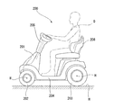
この電動車両としては、例えば図22に示すような4輪式の電動車両200が知られている(例えば、特許文献1参照)。この電動車両200では、駆動手段によって後輪203を回転駆動させることで、車体201を前方または後方に走行させるとともに、ステアリング機構205を操作して前輪202の向きを変更させることで、車体201を旋回させるようになっている。
2. Description of the Related Art Conventionally, small electric vehicles having a structure suitable for low-speed traveling have been widespread so that elderly people, physically handicapped people, and the like can be easily used.
As this electric vehicle, for example, a four-wheel
しかしながら、上述した電動車両200は、前後および前後に進みながら右もしくは左に旋回することができるが、真横に移動することができない。
However, the
本発明は、上記問題を解決すべくなされたもので、その目的は、従来の操作系のインターフェースを活かしながら真横への移動を指示することができる電動車両を提供することにある。 The present invention has been made to solve the above-described problems, and an object of the present invention is to provide an electric vehicle capable of instructing a movement to the side while utilizing an interface of a conventional operation system.
上記問題を解決するために、請求項1に記載した発明は、基体(例えば、実施形態による車体2)と、全方向に駆動可能な全方向駆動車輪を少なくとも1以上有する移動動作部(例えば、実施形態による前輪3、後輪4)と、前記基体に取り付けられた着座部(例えば、実施形態による着座部150)と、を備えた電動車両(例えば、実施形態による電動車両1)であって、加減速の指令を検出する加減速指令手段(例えば、実施形態によるコントローラ6)と、旋回の指令を検出する旋回指令手段(例えば、実施形態によるコントローラ6)と、前記基体の傾きを検出する傾き検出手段(例えば、実施形態による傾斜センサ52)と、前記加減速指令手段が検出した前記加減速の指令に基づいて前記基体の加減速の制御を行い、前記旋回指令手段が検出した前記旋回の指令に基づいて前記基体の旋回の制御を行い、前記加減速指令手段が前記加減速の指令を検出しておらず且つ前記旋回指令手段が前記旋回の指令を検出しておらず且つ前記傾き検出手段が前記基体の傾きを検出した場合、前記傾き検出手段が検出した前記基体の傾きに基づいて前記基体の並進を制御する制御部(例えば、実施形態による制御ユニット50)と、を備えたことを特徴とする電動車両である。これにより、加減速指令手段は加減速の指令を検出し、旋回指令手段は旋回の指令を検出し、傾き検出手段は基体の傾きを検出し、制御部は、加減速指令手段が検出した加減速の指令に基づいて基体の加減速の制御を行い、旋回指令手段が検出した旋回の指令に基づいて基体の旋回の制御を行い、加減速指令手段が加減速の指令を検出しておらず且つ旋回指令手段が旋回の指令を検出しておらず且つ傾き検出手段が基体の傾きを検出した場合、傾き検出手段が検出した基体の傾きに基づいて基体の並進を制御する。
請求項2に記載した発明は、前記制御部は、旋回時に前記基体が傾斜するように前記基体の旋回の制御を行うことを特徴とする。これにより、電動車両は、旋回時に基体が傾斜した状態で移動する。
請求項3に記載した発明は、少なくとも前記基体の速度又は加速度に応じて旋回時の回転中心位置を決定する回転中心位置決定手段を備えたことを特徴とする。これにより、電動車両は、速度又は加速度に応じた回転中心位置を中心として旋回する。
In order to solve the above-described problem, the invention described in
The invention described in
According to a third aspect of the present invention, there is provided rotation center position determining means for determining a rotation center position during turning in accordance with at least the speed or acceleration of the substrate. Thus, the electric vehicle turns around the rotation center position corresponding to the speed or acceleration.
上記問題を解決するために、請求項4に記載した発明は、基体(例えば、実施形態による車体2)と、前記基体に取り付けられ、全方向に駆動可能な第1の全方向駆動車輪(例えば、実施形態による前輪3)と、対称軸が前記第1の全方向駆動車輪の対称軸と平行になるように前記基体に取り付けられた第2の全方向駆動車輪(例えば、実施形態による後輪4)と、前記第1の全方向駆動車輪の車輪中心と前記第2の全方向駆動車輪の車輪中心とを結んだ直線が前後方向を規定するように取り付けられた着座部(例えば、実施形態による着座部150)と、を備えた電動車両(例えば、実施形態による電動車両1)であって、加減速の指令を検出する加減速指令手段(例えば、実施形態によるコントローラ6)と、旋回の指令を検出する旋回指令手段(例えば、実施形態によるコントローラ6)と、前記基体の傾きを検出する傾き検出手段(例えば、実施形態による傾斜センサ52)と、前記加減速指令手段が検出した前記加減速の指令に基づいて前記基体の加減速の制御を行い、前記旋回指令手段が検出した前記旋回の指令に基づいて前記基体の旋回の制御を行い、前記加減速指令手段が前記加減速の指令を検出しておらず且つ前記旋回指令手段が前記旋回の指令を検出しておらず且つ前記傾き検出手段が前記基体の傾きを検出した場合、前記傾き検出手段が検出した前記基体の傾きに基づいて前記基体の並進を制御する制御部(例えば、実施形態による制御ユニット50)と、を備えたことを特徴とする電動車両である。これにより、加減速指令手段は加減速の指令を検出し、旋回指令手段は旋回の指令を検出し、傾き検出手段は基体の傾きを検出し、制御部は、加減速指令手段が検出した加減速の指令に基づいて基体の加減速の制御を行い、旋回指令手段が検出した旋回の指令に基づいて基体の旋回の制御を行い、加減速指令手段が加減速の指令を検出しておらず且つ旋回指令手段が旋回の指令を検出しておらず且つ傾き検出手段が基体の傾きを検出した場合、傾き検出手段が検出した基体の傾きに基づいて基体の並進を制御する。
請求項5に記載した発明は、前記着座部の前後方向と、前記直線とが平行であることを特徴とする。これにより、電動車両は、着座部の前後方向に、車輪の中心を結んだ直線の方向を一致させた状態で移動する。
In order to solve the above problem, the invention described in
The invention described in
請求項1及び4に記載した発明によれば、加減速指令手段は加減速の指令を検出し、旋回指令手段は旋回の指令を検出し、傾き検出手段は基体の傾きを検出し、制御部は、加減速指令手段が検出した加減速の指令に基づいて基体の加減速の制御を行い、旋回指令手段が検出した旋回の指令に基づいて基体の旋回の制御を行い、加減速指令手段が加減速の指令を検出しておらず且つ旋回指令手段が旋回の指令を検出しておらず且つ傾き検出手段が基体の傾きを検出した場合、傾き検出手段が検出した基体の傾きに基づいて基体の並進を制御する。これにより、電動車両は、加減速の指令に応じた加減速や、旋回の指令に応じた旋回に加えて、基体の傾きに応じて並進することがことができる。 According to the first and fourth aspects of the invention, the acceleration / deceleration command means detects an acceleration / deceleration command, the turning command means detects a turning command, the inclination detecting means detects the inclination of the base, and the control unit Controls acceleration / deceleration of the substrate based on the acceleration / deceleration command detected by the acceleration / deceleration command means , and controls turning of the substrate based on the rotation command detected by the rotation command means. If the acceleration / deceleration command is not detected, the turn command means does not detect the turn command, and the tilt detection means detects the tilt of the base, the base is based on the tilt of the base detected by the tilt detection means Control the translation of. Thereby, the electric vehicle can translate according to the inclination of the base in addition to the acceleration / deceleration according to the acceleration / deceleration command and the turn according to the turn command.
請求項2に記載した発明によれば、旋回時に基体が傾斜するので、旋回時にも安定した乗り心地を達成することができる。
請求項3に記載した発明によれば、速度又は加速度に応じた回転中心位置を中心として旋回することで、自然な旋回をすることができる。
請求項5に記載した発明によれば、着座部の前後方向と、第1の全方向駆動車輪の車輪中心と第2の全方向駆動車輪の車輪中心とを結んだ直線とが平行である。これにより、乗り心地を向上させることができる。
According to the second aspect of the present invention, since the base body is inclined during turning, a stable riding comfort can be achieved even during turning.
According to the invention described in
According to the fifth aspect of the present invention, the front-rear direction of the seating part and the straight line connecting the wheel center of the first omnidirectional drive wheel and the wheel center of the second omnidirectional drive wheel are parallel. Thereby, riding comfort can be improved.
以下、本発明に係る実施形態を図面に基づいて説明する。
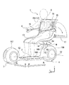
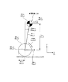
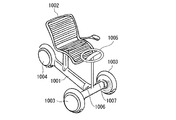
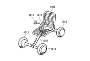
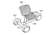
図1は電動車両を前側から見た斜視図であり、図2は後側から見た斜視図である。
図1,図2に示すように、本実施形態の電動車両1は、車体2(基体)と、車体2の前後に取り付けられた全方向移動車両である前輪3(第1の全方向駆動車輪)及び後輪4と、後輪4(第2の全方向駆動車輪)の上方に配置され乗員(利用者)Dが電動車両1の前向きに着座可能な着座部150とを備えている。
Embodiments according to the present invention will be described below with reference to the drawings.
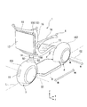
FIG. 1 is a perspective view of an electric vehicle viewed from the front side, and FIG. 2 is a perspective view of the electric vehicle viewed from the rear side.
As shown in FIGS. 1 and 2, the
車体2は、前輪3及び後輪4間を架け渡すように形成されたステップフロア159と、前輪3及び後輪4を構成する前輪フェンダー157及び後輪フェンダー158と、後輪フェンダー158と着座部150とを連結する連結部160とを備えている。
ステップフロア159は、路面Tとの間に間隔を空けた状態で路面Tと平行に延在する平板状の部材であり、その上面に乗員Dの足部や荷物等を載置可能に構成されている。そして、ステップフロア159の前端部には、前輪3の前輪フェンダー157が連結される一方、後端部には後輪4の後輪フェンダー158が連結されている。
連結部160は、上方に向かって延在する円柱状の部材であり、下端が後輪フェンダー158の上部に連結される一方、上端に着座部150が連結されている。
The
The
The connecting
着座部150は、乗員Dが乗車するための側面視L字状のシート部12と、シート部12及び上述した連結部160を連結するベース部160とを備えている。シート部12は、前後方向に延在して乗員Dの尻部及び大腿部を支持する座面部13と、座面部13の後端部から上方に向かって延在して乗員Dの背部を支持するシートバック15とを備えている。
The
シートバック15の左右方向両端部には、高さ方向中間部から前方に向かって延出する一対のアームレスト16が設けられている。これらアームレスト16は、シートバック15に対してピッチ軸(前後方向に直交する軸)周りに回動可能に支持されている。なお、アームレスト16の先端には、電動車両1の移動動作を乗員Dの手で操舵するためのコントローラ6が設置されている。また、シートバック15の上端部には、左右方向に沿って延在する手すり18が設けられており、この手すり18にバック等の荷物が掛止できるようになっている。また、シートバック15の後側には、可倒式の荷台17が設けられている。この荷台17は、シートバック15の下端側にピッチ軸周りに傾動可能に支持されている。具体的に、荷台17は未使用時においてはシートバック15と略平行に延在するように配置される(図2参照)一方、使用時においてはシートバック15に略直交する位置まで傾動して(図1参照)、その上面に荷物等を載置できるようになっている。
A pair of
ベース部160は、その上端部が座面部13の下面に連結される一方、下端部が図示しない駆動機構を介して連結部160の上端に連結されている。そして、着座部150は、駆動機構によってヨー軸(路面T(図4参照)の法線)周りに回転可能に構成されている(図1中矢印M参照)。
The
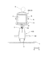
図3は電動車両を後側から見た背面図である。図1および図2と同様の構成には同様の符号を付している。また、図3には乗員Dと電動車両1とを合わせた全体の重心点Gが示されている。
FIG. 3 is a rear view of the electric vehicle as viewed from the rear side. Components similar to those in FIGS. 1 and 2 are denoted by the same reference numerals. FIG. 3 shows the center of gravity G of the entire occupant D and the
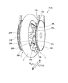
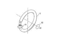
図4は後輪の拡大断面図であり、図5は後輪の斜視図である。また、図6は主輪の斜視図であり、図7は主輪とフリーローラとの配置関係を示す図である。なお、前輪と後輪とはともに同様の構成であるため、以下の説明では後輪を例として説明する。また、図4では後輪フェンダー及び主輪の一部のみを断面図として示している。 FIG. 4 is an enlarged cross-sectional view of the rear wheel, and FIG. 5 is a perspective view of the rear wheel. FIG. 6 is a perspective view of the main wheel, and FIG. 7 is a view showing the arrangement relationship between the main wheel and the free roller. Since both the front wheel and the rear wheel have the same configuration, the following description will be made taking the rear wheel as an example. FIG. 4 shows only a part of the rear wheel fender and the main wheel as a cross-sectional view.
図4〜図7に示すように、後輪4は、ゴム状弾性材等により円環状に形成された主輪5を有し、この主輪5はほぼ円形の横断面形状を有する。主輪5は、その弾性変形によって、図6及び図7の矢印Y1で示すように、円形の横断面の中心C1(具体的には、円形の横断面中心C1を通って、主輪5の軸心と同心となる円周線)の周りに回転可能となっている。
As shown in FIGS. 4 to 7, the
主輪5は、その軸心C2(主輪5全体の直径方向に直交する軸心C2)が電動車両1の左右方向に一致した状態で、後輪フェンダー158の内側に配置され、主輪5の外周面の下端部にて路面Tに接地している。なお、後輪フェンダー158は、側面視で円形状に形成されるとともに、下方に向けて開口するドーム状の部材であり、後輪4における下端部を除くほぼ全体を覆うように配置されている。
The
そして、主輪5は、アクチュエータ装置7による駆動(詳細は後述する)によって、図6の矢印Y2で示すように主輪5の軸心C2の周りに回転する動作(路面T上を輪転する動作)と、主輪5の横断面中心C1の周りに回転する動作とを行なうことが可能である。その結果、主輪5は、それらの回転動作の複合動作によって、路面T上を全方向に移動することが可能となっている。
The
アクチュエータ装置7は、主輪5と後輪フェンダー158の右側壁21Rとの間に介装される回転部材27R及びフリーローラ29Rと、主輪5と後輪フェンダー158の左側壁21Lとの間に介装される回転部材27L及びフリーローラ29Lと、回転部材27R及びフリーローラ29Rの上方に配置されたアクチュエータとしての電動モータ31Rと、回転部材27L及びフリーローラ29Lの上方に配置されたアクチュエータとしての電動モータ31Lとを備えている。
The
電動モータ31R,31Lは、それぞれのハウジングが後輪フェンダー158の両側壁21R,21Lに各々取付けられている。なお、図示は省略するが、電動モータ31R,31Lの電源(蓄電器)は、車体2の適所に搭載されている。
The
回転部材27Rは、左右方向の軸心を有する支軸33Rを介して右側壁21Rに回転可能に支持されている。同様に、回転部材27Lは、左右方向の軸心を有する支軸33Lを介して左側壁21Lに回転可能に支持されている。この場合、回転部材27Rの回転軸心(支軸33Rの軸心)と、回転部材27Lの回転軸心(支軸33Lの軸心)とは同軸心である。
The rotating
回転部材27R,27Lは、それぞれ電動モータ31R,31Lの出力軸に、減速機としての機能を含む動力伝達機構を介して接続されており、電動モータ31R,31Lからそれぞれ伝達される動力(トルク)によって回転駆動される。各動力伝達機構は、例えばプーリ・ベルト式のものである。すなわち、図4に示すように、回転部材27Rは、プーリ35Rとベルト37Rとを介して電動モータ31Rの出力軸に接続されている。同様に、回転部材27Lは、プーリ35Lとベルト37Lとを介して電動モータ31Lの出力軸に接続されている。
The rotating
なお、上述した動力伝達機構は、例えば、スプロケットとリンクチェーンとにより構成されるもの、あるいは、複数のギヤにより構成されるものであってもよい。また、例えば、電動モータ31R,31Lを、それぞれの出力軸が各回転部材27R,27Lと同軸心になるように各回転部材27R,27Lに対向させて配置し、電動モータ31R,31Lのそれぞれの出力軸を回転部材27R,27Lに各々、減速機(遊星歯車装置等)を介して連結するようにしてもよい。
The power transmission mechanism described above may be constituted by, for example, a sprocket and a link chain, or constituted by a plurality of gears. In addition, for example, the
各回転部材27R,27Lは、主輪5側に向かって縮径する円錐台と同様の形状に形成されており、その外周面がテーパ外周面39R,39Lとなっている。
Each rotating
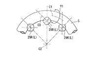
回転部材27Rのテーパ外周面39Rの周囲には、回転部材27Rと同心の円周上に等間隔で並ぶようにして、複数のフリーローラ29Rが配列されている。そして、これらのフリーローラ29Rは、それぞれ、ブラケット41Rを介してテーパ外周面39Rに取付けられ、ブラケット41Rに回転可能に支承されている。
A plurality of
同様に、回転部材27Lのテーパ外周面39Lの周囲には、回転部材27Lと同心の円周上に等間隔で並ぶようにして、複数(フリーローラ29Rと同数)のフリーローラ29Lが配列されている。そして、これらのフリーローラ29Lは、それぞれ、ブラケット41Lを介してテーパ外周面39Lに取付けられ、ブラケット41Lに回転可能に支承されている。
Similarly, a plurality (the same number as the
主輪5は、回転部材27R側のフリーローラ29Rと、回転部材27L側のフリーローラ29Lとの間に挟まれるようにして、回転部材27R,27Lと同軸心に配置されている。
The
この場合、図7に示すように、各フリーローラ29R,29Lは、その軸心C3が主輪5の軸心C2に対して傾斜するとともに、主輪5の直径方向(主輪5をその軸心C2の方向で見たときに、軸心C2と各フリーローラ29R,29Lとを結ぶ径方向)に対して傾斜する姿勢で配置されている。そして、このような姿勢で、各フリーローラ29R,29Lのそれぞれの外周面が主輪5の内周面に斜め方向に圧接されている。
In this case, as shown in FIG. 7, each of the
より一般的に言えば、右側のフリーローラ29Rは、回転部材27Rが軸心C2の周りに回転駆動されたときに、主輪5との接触面で、軸心C2周りの方向の摩擦力成分(主輪5の内周の接線方向の摩擦力成分)と、主輪5の横断面中心C1の周り方向の摩擦力成分(円形の横断面の接線方向の摩擦力成分)とを主輪5に作用させ得るような姿勢で、主輪5の内周面に圧接されている。左側のフリーローラ29Lについても同様である。
More generally speaking, the right
なお、前輪3は、上述した後輪4と同一の構成からなり、前輪3及び後輪4は、互いの主輪5の軸心(回転軸)C2が平行になるように配置されている(図1,図2参照)。そして、前輪3及び後輪4の電動モータ31R,31Lによりそれぞれ、回転部材27R,27Lを同方向に等速度で回転駆動させた場合には、各主輪5が回転部材27R,27Lと同方向に軸心C2の周りに回転することとなる。これにより、各主輪5が路面T上を前後方向に輪転して、電動車両1の全体が前後方向に移動することとなる。なお、この場合は、主輪5は、その横断面中心C1の周りには回転しない。
The
また、例えば回転部材27R,27Lを互いに逆方向に同じ大きさの速度で回転駆動させた場合には、各主輪5は、その横断面中心C1の周りに回転することとなる。これにより、各主輪5がその軸心C2の方向(すなわち左右方向)に移動し、ひいては、電動車両1の全体が左右方向に移動することとなる。なお、この場合は、主輪5は、その軸心C2の周りには回転しない。
Further, for example, when the
さらに、回転部材27R,27Lを、互いに異なる速度(方向を含めた速度)で、同方向又は逆方向に回転駆動させた場合には、各主輪5は、その軸心C2の周りに回転すると同時に、その横断面中心C1の周りに回転することとなる。
Further, when the
この時、これらの回転動作の複合動作(合成動作)によって、前後方向及び左右方向に対して傾斜した方向に主輪5が移動し、ひいては、電動車両1の全体が主輪5と同方向に移動することとなる。この場合の主輪5の移動方向は、回転部材27R,27Lの回転方向を含めた回転速度(回転方向に応じて極性が定義された回転速度ベクトル)の差に依存して変化するものとなる。
At this time, the
以上のように各主輪5の移動動作が行なわれるので、電動モータ31R,31Lのそれぞれの回転速度(回転方向を含む)を制御し、ひいては回転部材27R,27Lの回転速度を制御することによって、電動車両1の移動速度及び移動方向を制御できることとなる。
Since the
次に、本実施形態の電動車両1の動作制御のための構成を説明する。なお、以降の説明では、図1及び図2に示すように、前後方向の水平軸をX軸、左右方向の水平軸をY軸、鉛直方向をZ軸とするXYZ座標系を想定し、前後方向、左右方向をそれぞれX軸方向、Y軸方向と言うことがある。
Next, the structure for operation control of the
また、本実施形態において、電動車両1は、Y軸方向に移動する方法としては、前輪3と後輪4とがY軸方向の同じ方向に駆動する並進と、前輪3と後輪4とがY軸方向の互いに逆向きに駆動する旋回との2つの方法がある。
Further, in the present embodiment, the
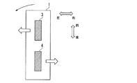
図8は、電動車両1が並進する際の前輪3と後輪4との駆動方向を示した上面図である。図示する例では、電動車両1が左側に並進するように、前輪3と後輪4とが同じ方向に駆動している。図9は、電動車両1が旋回する際の前輪3と後輪4との駆動方向を示した上面図である。図示する例では、電動車両1が左回りに旋回するように、前輪3と後輪4とが互いの逆の方向に駆動している。
FIG. 8 is a top view showing the driving directions of the
まず、電動車両1の概略的な動作制御を説明すると、基本的に本実施形態の電動車両1では、シート部12に着座した乗員Dが、コントローラ6を傾けた場合、コントローラ6を傾けた側に電動車両1が移動するように、主輪5の移動動作が制御される。また、乗員Dがコントローラ6を操作することなく、右または左に体重をかけた場合、体重をかけた側に電動車両1が並進する。これらの動作が、電動車両1に対する1つの基本的な操縦操作(電動車両1の動作要求)とされ、その操縦操作に応じて主輪5の移動動作がアクチュエータ装置7を介して制御される。
First, schematic operation control of the
具体的には、コントローラ6が傾いた角度、またはコントローラ6が傾いていない場合は乗員Dが右または左に体重をかけて電動車両1の傾いた角度に応じて、電動車両1は移動する。このとき、電動車両1が倒れないように、電動車両1(及び乗員Dの全体)の重心点Gが、後輪4の中心点のほぼ真上に位置する状態(具体的には電動車両1の前後方向から見て重心点Gが後輪4の接地点(路面Tにおいて重心点Gまでの距離が最短となる点)のほぼ真上に位置する状態)での車体2の姿勢を目標姿勢とし、基本的には、車体2の実際の姿勢を目標姿勢に収束させるように、前輪3及び後輪4の移動動作が制御される。
Specifically, the
すなわち、電動車両1の上下方向が重力方向に一致するように前輪3及び後輪4の移動動作が制御される。具体的に、目標姿勢に対して重心点Gが左右方向に移動したと判断された場合には、各主輪5を中心C1周りに回転させて電動車両1を左右方向に移動させる。または、これらの回転動作の複合動作によって、車体2の姿勢が目標姿勢に収束される。したがって、電動車両1を並進させたい場合には、乗員D自身の重心点を右または左に傾ける。すると、電動車両1は、目標姿勢を保とうとして左または右に移動することになる。また、電動車両1を前後または前後に移動しながら左右に移動させたい場合は、乗員Dはコントローラ6を移動させたい方向に傾ける。すると、電動車両1は、コントローラ6で検出された傾きに応じて前後または前後に移動しながら左右に移動する。
That is, the movement operation of the
以上の動作を行うために、本実施形態ではマイクロコンピュータや電動モータ31R,31Lのドライブ回路ユニットなどを含む電子回路ユニットにより構成された制御ユニット50(制御部)や、電動車両1の移動方向の指示を検出するコントローラ6や、車体2の所定の部位の重力方向に対する傾斜角θb及びその変化速度(=dθb/dt)を計測するための傾斜センサ52と、電動車両1に乗員Dが搭乗しているか否かを検知するための荷重センサ54と、電動モータ31R,31Lのそれぞれの出力軸の回転角度及び回転角速度を検出するための角度センサとしてのロータリーエンコーダ56R,56L(図4参照)等がそれぞれ、電動車両1の適所に搭載されている。
In order to perform the above operation, in the present embodiment, a control unit 50 (control unit) constituted by an electronic circuit unit including a microcomputer and a drive circuit unit of the
この場合、制御ユニット50及び傾斜センサ52は、例えば、車体2の内部に収容された状態で取付けられている。また、荷重センサ54は、シート部13に内蔵されている。また、ロータリーエンコーダ56R,56Lは、それぞれ、電動モータ31R,31Lと一体に設けられている。なお、ロータリーエンコーダ56R,56Lは、それぞれ、回転部材27R,27Lに装着してもよい。
In this case, the
上記傾斜センサ52は、より詳しくは、加速度センサとジャイロセンサ等のレートセンサ(角速度センサ)とから構成され、これらのセンサの検出信号を制御ユニット50に出力する。そして、制御ユニット50が、傾斜センサ52の加速度センサ及びレートセンサの出力を基に、所定の計測演算処理(これは公知の演算処理でよい)を実行することによって、傾斜センサ52を搭載した部位の、鉛直方向に対する傾斜角度θbの計測値とその変化速度(微分値)である傾斜角速度θbdotの計測値とを算出する。
More specifically, the
この場合、計測する傾斜角度θb(以降、基体傾斜角度θbということがある)は、より詳しくは、それぞれ、Y軸周り方向(ピッチ方向)の成分θb_xと、X軸周り方向(ロール方向)の成分θb_yとから成る。同様に、計測する傾斜角速度θbdot(以降、基体傾斜角速度θbdotということがある)も、Y軸周り方向(ピッチ方向)の成分θbdot_x(=dθb_x/dt)と、X軸周り方向(ロール方向)の成分θbdot_y(=dθb_y/dt)とから成る。 In this case, the tilt angle θb to be measured (hereinafter also referred to as the base body tilt angle θb) is more specifically, the component θb_x in the Y axis direction (pitch direction) and the X axis direction (roll direction), respectively. It consists of component θb_y. Similarly, the measured tilt angular velocity θbdot (hereinafter also referred to as the base tilt angular velocity θbdot) is also measured in the Y-axis direction (pitch direction) component θbdot_x (= dθb_x / dt) and the X-axis direction (roll direction). Component θbdot_y (= dθb_y / dt).
なお、本実施形態の説明では、上記基体傾斜角度θbなど、X軸及びY軸の各方向(又は各軸周り方向)の成分を有する運動状態量等の変数、あるいは、該運動状態量に関連する係数等の変数に関しては、その各成分を区別して表記する場合に、該変数の参照符号に、添え字“_x”又は“_y”を付加する。 In the description of the present embodiment, a variable such as a motion state quantity having a component in each direction of the X axis and the Y axis (or a direction around each axis) such as the base body inclination angle θb, or a relation to the motion state quantity. For a variable such as a coefficient to be processed, a suffix “_x” or “_y” is added to the reference symbol of the variable when each component is expressed separately.
この場合において、並進速度等の並進運動に係わる変数については、そのX軸方向の成分に添え字“_x”を付加し、Y軸方向の成分に添え字“_y”を付加する。 In this case, for a variable related to translational motion such as translational speed, a subscript “_x” is added to the component in the X-axis direction, and a subscript “_y” is added to the component in the Y-axis direction.
一方、角度、回転速度(角速度)、角加速度など、回転運動に係わる変数については、並進運動に係わる変数と添え字を揃えるために、便宜上、Y軸周り方向の成分に添え字“_x”を付加し、X軸周り方向の成分に添え字“_y”を付加する。 On the other hand, for variables related to rotational motion, such as angle, rotational speed (angular velocity), angular acceleration, etc., the subscript “_x” is added to the component around the Y axis for convenience in order to align the subscript with the variable related to translational motion. In addition, the subscript “_y” is added to the component around the X axis.
さらに、X軸方向の成分(又はY軸周り方向の成分)と、Y軸方向の成分(又はX軸周り方向の成分)との組として変数を表記する場合には、該変数の参照符号に添え字“_xy”を付加する。例えば、上記基体傾斜角度θbを、Y軸周り方向の成分θb_xとX軸周り方向の成分θb_yの組として表現する場合には、「基体傾斜角度θb_xy」というように表記する。 Further, when a variable is expressed as a set of a component in the X-axis direction (or a component around the Y-axis) and a component in the Y-axis direction (or a component around the X-axis), the reference numeral of the variable The subscript “_xy” is added. For example, when the base body tilt angle θb is expressed as a set of a component θb_x around the Y axis and a component θb_y around the X axis, it is expressed as “base body tilt angle θb_xy”.
前記荷重センサ54は、乗員がシート部13に着座した場合に該乗員の重量による荷重を受けるようにシート部13に内蔵され、その荷重に応じた検出信号を制御ユニット50に出力する。そして、制御ユニット50が、この荷重センサ54の出力により示される荷重の計測値に基づいて、電動車両1に乗員が搭乗しているか否かを判断する。
The
なお、荷重センサ54の代わりに、例えば、乗員がシート部13に着座したときにONとなるようなスイッチ式のセンサを用いてもよい。
Instead of the
ロータリーエンコーダ56Rは、電動モータ31Rの出力軸が所定角度回転する毎にパルス信号を発生し、このパルス信号を制御ユニット50に出力する。そして、制御ユニット50が、そのパルス信号を基に、電動モータ53Rの出力軸の回転角度を計測し、さらにその回転角度の計測値の時間的変化率(微分値)を電動モータ53Rの回転角速度として計測する。電動モータ31L側のロータリーエンコーダ56Lについても同様である。
The
制御ユニット50は、上記の各計測値を用いて所定の演算処理を実行することによって、電動モータ31R,31Lのそれぞれの回転角速度の目標値である速度指令を決定し、その速度指令に従って、電動モータ31R,31Lのそれぞれの回転角速度をフィードバック制御する。
The
なお、電動モータ31Rの出力軸の回転角速度と、回転部材27Rの回転角速度との間の関係は、該出力軸と回転部材27Rとの間の一定値の減速比に応じた比例関係になるので、本実施形態の説明では、便宜上、電動モータ31Rの回転角速度は、回転部材27Rの回転角速度を意味するものとする。同様に、電動モータ31Lの回転角速度は、回転部材27Lの回転角速度を意味するものとする。
The relationship between the rotational angular velocity of the output shaft of the
以下に、制御ユニット50の制御処理をさらに詳細に説明する。
制御ユニット50は、所定の制御処理周期で図10のフローチャートに示す処理(メインルーチン処理)を実行する。
Hereinafter, the control process of the
The
まず、ステップS1において、制御ユニット50は、コントローラ6に入力された移動方向を示す移動方向指示情報および傾斜センサ52の出力を取得する。
次いで、ステップS2に進んで、制御ユニット50は、取得した傾斜センサ52の出力を基に、基体傾斜角度θbの計測値θb_xy_sと、基体傾斜角速度θbdotの計測値θbdot_xy_sとを算出する。
但し、本実施形態では、電動車両1は二輪車であり、以降の説明を簡略化するため、x方向の基体傾斜角度θbの計測値θb_x_s=0とし、基体傾斜角速度θbdotの計測値θbdot_x_s=0とする。
First, in step S <b> 1, the
Next, the process proceeds to step S2, and the
However, in the present embodiment, the
なお、以降の説明では、上記計測値θb_xy_sなど、変数(状態量)の実際の値の観測値(計測値又は推定値)を参照符号により表記する場合に、該変数の参照符号に、添え字“_s”を付加する。 In the following description, when an observed value (measured value or estimated value) of an actual value of a variable (state quantity) such as the measured value θb_xy_s is represented by a reference symbol, a subscript is added to the reference symbol of the variable. Add “_s”.
次いで、制御ユニット50は、ステップS3において、荷重センサ54の出力を取得した後、ステップS4の判断処理を実行する。この判断処理においては、制御ユニット50は、取得した荷重センサ54の出力が示す荷重計測値があらかじめ設定された所定値よりも大きいか否かによって、電動車両1に乗員が搭乗しているか否か(シート部13に乗員が着座しているか否か)を判断する。
Next, after acquiring the output of the
そして、制御ユニット50は、ステップS4の判断結果が肯定的である場合には、基体傾斜角度θbの目標値θb_xy_objを設定する処理と、電動車両1の動作制御用の定数パラメータ(各種ゲインの基本値など)の値を設定する処理とを、それぞれステップS5、6で実行する。
If the determination result in step S4 is affirmative, the
ステップS5においては、制御ユニット50は、Y軸方向の基体傾斜角度θbの目標値θb_y_objとして、あらかじめ定められた搭乗モード用の目標値を設定する。
In step S5, the
ここで、「搭乗モード」は、電動車両1に乗員が搭乗している場合での電動車両1の動作モードを意味する。この搭乗モード用の目標値θb_y_objは、電動車両1とシート部13に着座した乗員との全体の重心点(以降、電動車両・乗員全体重心点という)が車輪体5の接地面のほぼ真上に位置する状態となる基体9の姿勢において、傾斜センサ52の出力に基づき計測される基体傾斜角度θbの計測値θb_y_sに一致又はほぼ一致するようにあらかじめ設定されている。
Here, the “boarding mode” means an operation mode of the
また、ステップS6においては、制御ユニット50は、電動車両1の動作制御用の定数パラメータの値として、あらかじめ定められた搭乗モード用の値を設定する。なお、定数パラメータは、後述するhx,hy,Ki_a_x,Ki_b_x,Ki_a_y,Ki_b_y(i=1,2,3)等である。
In step S <b> 6, the
一方、ステップS4の判断結果が否定的である場合には、制御ユニット50は、Y軸方向の基体傾斜角度θb_yの目標値θb_y_objを設定する処理と、電動車両1の動作制御用の定数パラメータの値を設定する処理とを、ステップS7、8で実行する。
On the other hand, if the determination result in step S4 is negative, the
ステップS7においては、制御ユニット50は、傾斜角度θbの目標値θb_y_objとして、あらかじめ定められた自立モード用の目標値を設定する。
In step S7, the
ここで、「自立モード」は、電動車両1に乗員が搭乗していない場合での電動車両1の動作モードを意味する。この自立モード用の目標値θb_y_objは、電動車両1単体の重心点(以降、電動車両単体重心点という)が車輪体5の接地面のほぼ真上に位置する状態となる基体9の姿勢において、傾斜センサ52の出力に基づき計測される基体傾斜角度θbの計測値θb_y_sに一致又はほぼ一致するようにあらかじめ設定されている。この自立モード用の目標値θb_y_objは、搭乗モード用の目標値θb_y_objと一般的には異なる。
Here, the “self-supporting mode” means an operation mode of the
また、ステップS8においては、制御ユニット50は、電動車両1の動作制御用の定数パラメータの値として、あらかじめ定められた自立モード用の値を設定する。この自立モード用の定数パラメータの値は、搭乗モード用の定数パラメータの値と異なる。
In step S <b> 8,
搭乗モードと自立モードとで、上記定数パラメータの値を異ならせるのは、それぞれのモードで上記重心点の高さや、全体質量等が異なることに起因して、制御入力に対する電動車両1の動作の応答特性が互いに異なるからである。 The constant parameter value is different between the boarding mode and the self-sustaining mode because the height of the center of gravity, the overall mass, and the like are different in each mode. This is because the response characteristics are different from each other.
以上のステップS4〜8の処理によって、搭乗モード及び自立モードの動作モード毎に個別に、基体傾斜角度θb_yの目標値θb_y_objと定数パラメータの値とが設定される。 Through the processes in steps S4 to S8 described above, the target value θb_y_obj of the base body tilt angle θb_y and the value of the constant parameter are individually set for each operation mode of the boarding mode and the self-supporting mode.
なお、ステップS5,6の処理、又はステップS7,8の処理は、制御処理周期毎に実行することは必須ではなく、ステップS4の判断結果が変化した場合にだけ実行するようにしてもよい。 Note that it is not essential to execute the processes of steps S5 and S6 or the processes of steps S7 and S8, and may be executed only when the determination result of step S4 changes.
補足すると、搭乗モード及び自立モードのいずれにおいても、基体傾斜角速度θbdotのY軸周り方向の成分θbdot_xの目標値とX軸周り方向の成分θbdot_yの目標値とは、いずれも“0”である。このため、基体傾斜角速度θbdot_xyの目標値を設定する処理は不要である。また、本実施形態では、電動車両1は二輪車であり、以降の説明を簡略化するため、制御ユニット50はY軸周りの基体傾斜角速度θbdotの制御を行わないとする。即ち、基体傾斜角速度θbdotのY軸周り方向の成分θbdot_x=0とする制御を行わないとする。
Supplementally, in both the boarding mode and the self-supporting mode, the target value of the component θbdot_x around the Y axis and the target value of the component θbdot_y around the X axis of the base body tilt angular velocity θbdot are both “0”. For this reason, the process which sets the target value of base | substrate inclination angular velocity (theta) bdot_xy is unnecessary. In the present embodiment, the
以上の如くステップS5,6の処理、又はステップS7,8の処理を実行した後、制御ユニット50は、次にステップS9において、電動車両制御演算処理を実行することによって、前輪3および後輪4の電動モータ31R,31Lのそれぞれの速度指令を決定する。この電動車両制御演算処理の詳細は後述する。なお、先述したとおり本実施形態の電動車両1は二輪車であり、以降の説明を簡略化するため、X方向の傾き成分に関しては無視するものとする。すなわち、以下の説明において、基体傾斜角度θbの計測値θb_x_s=0とし、基体傾斜角速度θbdotの計測値θbdot_x_s=0とする。
After executing the processing of steps S5 and S6 or the processing of steps S7 and 8 as described above, the
次いで、ステップS10に進んで、制御ユニット50は、ステップS9で決定した速度指令に応じて前輪3および後輪4の電動モータ31R,31Lの動作制御処理を実行する。この動作制御処理では、制御ユニット50は、ステップS9で決定した電動モータ31Rの速度指令と、ロータリーエンコーダ56Rの出力に基づき計測した電動モータ31Rの回転速度の計測値との偏差に応じて、該偏差を“0”に収束させるように電動モータ31Rの出力トルクの目標値(目標トルク)を決定する。そして、制御ユニット50は、その目標トルクの出力トルクを電動モータ31Rに出力させるように該電動モータ31Rの通電電流を制御する。左側の電動モータ31Lの動作制御についても同様である。
以上が、制御ユニット50が実行する全体的な制御処理である。
Next, the process proceeds to step S10, and the
The above is the overall control process executed by the
次に、上記ステップS9の電動車両制御演算処理の詳細を説明する。
なお、以降の説明においては、前輪3の制御と後輪4の制御とが同一の場合、特に分けずに説明している。
Next, details of the electric vehicle control calculation process in step S9 will be described.
In the following description, when the control of the
また、以降の説明においては、前記搭乗モードにおける電動車両・乗員全体重心点と、前記自立モードにおける電動車両単体重心点とを総称的に、電動車両系重心点という。該電動車両系重心点は、電動車両1の動作モードが搭乗モードである場合には、電動車両・乗員全体重心点を意味し、自立モードである場合には、電動車両単体重心点を意味する。
In the following description, the center of gravity of the electric vehicle / occupant in the boarding mode and the center of gravity of the single electric vehicle in the independent mode are collectively referred to as the electric vehicle system center of gravity. When the operation mode of the
また、以降の説明では、制御ユニット50が各制御処理周期で決定する値(更新する値)に関し、現在の(最新の)制御処理周期で決定する値を今回値、その1つ前の制御処理周期で決定した値を前回値ということがある。そして、今回値、前回値を特にことわらない値は、今回値を意味する。
In the following description, regarding the value (value to be updated) determined by the
また、X軸方向の速度及び加速度に関しては、前方向きを正の向きとし、Y軸方向の速度及び加速度に関しては、左向きを正の向きとする。 Further, regarding the speed and acceleration in the X-axis direction, the forward direction is a positive direction, and regarding the speed and acceleration in the Y-axis direction, the left direction is a positive direction.
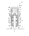
本実施形態では、前記電動車両系重心点の動力学的な挙動(詳しくは、Y軸方向からこれに直交する面(XZ平面)に投影して見た挙動と、X軸方向からこれに直交する面(YZ平面)に投影して見た挙動)が、近似的に、図11に示すような、倒立振子モデルの挙動(倒立振子の動力学的挙動)によって表現されるものとして、ステップS9の電動車両制御演算処理が行なわれる。 In the present embodiment, the dynamic behavior of the electric vehicle system center-of-gravity point (specifically, the behavior seen by projecting from the Y-axis direction onto a plane (XZ plane) orthogonal thereto, and the X-axis direction orthogonal to this) Step S9 is assumed that the behavior observed by projecting on the surface to be projected (YZ plane) is approximately expressed by the behavior of the inverted pendulum model (the dynamic behavior of the inverted pendulum) as shown in FIG. The electric vehicle control calculation process is performed.
なお、図11において、括弧を付していない参照符号は、Y軸方向から見た倒立振子モデルに対応する参照符号であり、括弧付きの参照符号は、X軸方向から見た倒立振子モデルに対応する参照符号である。 In FIG. 11, reference numerals without parentheses are reference numerals corresponding to the inverted pendulum model viewed from the Y-axis direction, and reference numerals with parentheses refer to the inverted pendulum model viewed from the X-axis direction. Corresponding reference sign.
この場合、Y軸方向から見た挙動を表現する倒立振子モデルは、電動車両系重心点に位置する質点60_xと、Y軸方向に平行な回転軸62a_xを有して床面上を輪転自在な仮想的な車輪62_x(以降、仮想車輪62_xという)とを備える。そして、質点60_xが、仮想車輪62_xの回転軸62a_xに直線状のロッド64_xを介して支持され、該回転軸62a_xを支点として該回転軸62a_xの周りに揺動自在とされている。 In this case, the inverted pendulum model expressing the behavior seen from the Y-axis direction has a mass point 60_x located at the center of gravity of the electric vehicle system and a rotation axis 62a_x parallel to the Y-axis direction, and can rotate on the floor surface. Virtual wheels 62_x (hereinafter referred to as virtual wheels 62_x). The mass point 60_x is supported by the rotation shaft 62a_x of the virtual wheel 62_x via the linear rod 64_x, and can swing around the rotation shaft 62a_x with the rotation shaft 62a_x as a fulcrum.
この倒立振子モデルでは、質点60_xの運動が、Y軸方向から見た電動車両系重心点の運動に相当する。また、鉛直方向に対するロッド64_xの傾斜角度θbe_xがY軸周り方向での基体傾斜角度計測値θb_x_sと基体傾斜角度目標値θb_x_objとの偏差θbe_x_s(=θb_x_s−θb_x_obj)に一致するものとされる。また、ロッド64_xの傾斜角度θbe_xの変化速度(=dθbe_x/dt)がY軸周り方向の基体傾斜角速度計測値θbdot_x_sに一致するものとされる。また、仮想車輪62_xの移動速度Vw_x(X軸方向の並進移動速度)は、電動車両1の車輪体5のX軸方向の移動速度に一致するものとされる。
In this inverted pendulum model, the motion of the mass point 60_x corresponds to the motion of the electric vehicle system center-of-gravity point viewed from the Y-axis direction. Further, the inclination angle θbe_x of the rod 64_x with respect to the vertical direction coincides with the deviation θbe_x_s (= θb_x_s−θb_x_obj) between the measured base body tilt angle value θb_x_s and the base body tilt angle target value θb_x_obj in the direction around the Y axis. Further, the changing speed (= dθbe_x / dt) of the inclination angle θbe_x of the rod 64_x is set to coincide with the measured body inclination angular velocity θbdot_x_s in the direction around the Y axis. Further, the moving speed Vw_x (translation moving speed in the X-axis direction) of the virtual wheel 62_x is set to coincide with the moving speed in the X-axis direction of the
同様に、X軸方向から見た挙動を表現する倒立振子モデル(図11の括弧付きの符号を参照)は、電動車両系重心点に位置する質点60_yと、X軸方向に平行な回転軸62a_yを有して床面上を輪転自在な仮想的な車輪62_y(以降、仮想車輪62_yという)とを備える。そして、質点60_yが、仮想車輪62_yの回転軸62a_yに直線状のロッド64_yを介して支持され、該回転軸62a_yを支点として該回転軸62a_yの周りに揺動自在とされている。 Similarly, an inverted pendulum model (see the reference numerals in parentheses in FIG. 11) expressing the behavior seen from the X-axis direction has a mass point 60_y located at the electric vehicle system center of gravity and a rotation axis 62a_y parallel to the X-axis direction. And a virtual wheel 62_y (hereinafter referred to as a virtual wheel 62_y) that can rotate on the floor surface. The mass point 60_y is supported by the rotation shaft 62a_y of the virtual wheel 62_y via a linear rod 64_y, and can swing around the rotation shaft 62a_y with the rotation shaft 62a_y as a fulcrum.
この倒立振子モデルでは、質点60_yの運動が、X軸方向から見た電動車両系重心点の運動に相当する。また、鉛直方向に対するロッド64_yの傾斜角度θbe_yがX軸周り方向での基体傾斜角度計測値θb_y_sと基体傾斜角度目標値θb_y_objとの偏差θbe_y_s(=θb_y_s−θb_y_obj)に一致するものとされる。また、ロッド64_yの傾斜角度θbe_yの変化速度(=dθbe_y/dt)がX軸周り方向の基体傾斜角速度計測値θbdot_y_sに一致するものとされる。また、仮想車輪62_yの移動速度Vw_y(Y軸方向の並進移動速度)は、電動車両1の車輪体5のY軸方向の移動速度に一致するものとされる。
In this inverted pendulum model, the motion of the mass point 60_y corresponds to the motion of the electric vehicle system center-of-gravity point viewed from the X-axis direction. In addition, the inclination angle θbe_y of the rod 64_y with respect to the vertical direction coincides with the deviation θbe_y_s (= θb_y_s−θb_y_obj) between the measured base body tilt angle value θb_y_s and the base body tilt angle target value θb_y_obj in the direction around the X axis. In addition, the change speed (= dθbe_y / dt) of the inclination angle θbe_y of the rod 64_y coincides with the measured base body inclination angular velocity θbdot_y_s in the direction around the X axis. Further, the moving speed Vw_y (translational moving speed in the Y-axis direction) of the virtual wheel 62_y matches the moving speed in the Y-axis direction of the
なお、仮想車輪62_x,62_yは、それぞれ、あらかじめ定められた所定値Rw_x,Rw_yの半径を有するものとされる。 The virtual wheels 62_x and 62_y are assumed to have predetermined radii of predetermined values Rw_x and Rw_y, respectively.
また、仮想車輪62_x,62_yのそれぞれの回転角速度ωw_x,ωw_yと、電動モータ31R,31Lのそれぞれの回転角速度ω_R,ω_L(より正確には、回転部材27R,27Lのそれぞれの回転角速度ω_R,ω_L)との間には、次式(01a),(01b)の関係が成立するものとされる。
Further, the rotational angular velocities ωw_x and ωw_y of the virtual wheels 62_x and 62_y and the rotational angular velocities ω_R and ω_L of the
ωw_x=(ω_R+ω_L)/2 式(01a)
ωw_y=C・(ω_R−ω_L)/2 式(01b)
ωw_x = (ω_R + ω_L) / 2 Formula (01a)
ωw_y = C · (ω_R−ω_L) / 2 Formula (01b)
なお、式(01b)における“C”は、前記フリーローラ29R,29Lと車輪体5との間の機構的な関係や滑りに依存する所定値の係数である。
Note that “C” in the equation (01b) is a coefficient of a predetermined value depending on the mechanical relationship between the
ここで、図11に示す倒立振子モデルの動力学は、次式(03x),(03y)により表現される。なお、式(03x)は、Y軸方向から見た倒立振子モデルの動力学を表現する式、式(03y)は、X軸方向から見た倒立振子モデルの動力学を表現する式である。 Here, the dynamics of the inverted pendulum model shown in FIG. 11 is expressed by the following equations (03x) and (03y). Expression (03x) is an expression expressing the dynamics of the inverted pendulum model viewed from the Y-axis direction, and Expression (03y) is an expression expressing the dynamics of the inverted pendulum model viewed from the X-axis direction.
d2θbe_x/dt2=α_x・θbe_x+β_x・ωwdot_x 式(03x)
d2θbe_y/dt2=α_y・θbe_y+β_y・ωwdot_y 式(03y)
d 2 θbe_x / dt 2 = α_x · θbe_x + β_x · ωwdot_x formula (03x)
d 2 θbe_y / dt 2 = α_y · θbe_y + β_y · ωwdot_y formula (03y)
式(03x)におけるωwdot_xは仮想車輪62_xの回転角加速度(回転角速度ωw_xの1階微分値)、α_xは、質点60_xの質量や高さh_xに依存する係数、β_xは、仮想車輪62_xのイナーシャ(慣性モーメント)や半径Rw_xに依存する係数である。式(03y)におけるωwdot_y、α_y、β_yについても上記と同様である。 In equation (03x), ωwdot_x is the rotational angular acceleration of the virtual wheel 62_x (first-order differential value of the rotational angular velocity ωw_x), α_x is a coefficient that depends on the mass and height h_x of the mass 60_x, and β_x is the inertia of the virtual wheel 62_x ( It is a coefficient depending on the moment of inertia) and the radius Rw_x. The same applies to ωwdot_y, α_y, and β_y in equation (03y).
これらの式(03x),(03y)から判るように、倒立振子の質点60_x,60_yの運動(ひいては電動車両系重心点の運動)は、それぞれ、仮想車輪62_xの回転角加速度ωwdot_x、仮想車輪62_yの回転角加速度ωwdot_yに依存して規定される。 As can be seen from these equations (03x) and (03y), the motions of the mass points 60_x and 60_y of the inverted pendulum (and hence the motion of the electric vehicle system center of gravity) are respectively the rotational angular acceleration ωwdot_x and the virtual wheel 62_y of the virtual wheel 62_x. It is defined depending on the rotational angular acceleration ωwdot_y.
そこで、本実施形態では、Y軸方向から見た電動車両系重心点の運動を制御するための操作量(制御入力)として、仮想車輪62_xの回転角加速度ωwdot_xを用いると共に、X軸方向から見た電動車両系重心点の運動を制御するための操作量(制御入力)として、仮想車輪62_yの回転角加速度ωwdot_yを用いる。 Therefore, in the present embodiment, the rotational angular acceleration ωwdot_x of the virtual wheel 62_x is used as the operation amount (control input) for controlling the motion of the electric vehicle system center-of-gravity point viewed from the Y-axis direction, and viewed from the X-axis direction. The rotational angular acceleration ωwdot_y of the virtual wheel 62_y is used as an operation amount (control input) for controlling the motion of the electric vehicle system center of gravity.
そして、ステップS9の電動車両制御演算処理を概略的に説明すると、制御ユニット50は、X軸方向で見た質点60_xの運動と、Y軸方向で見た質点60_yの運動とが、電動車両系重心点の所望の運動に対応する運動となるように、操作量としての上記回転角加速度ωwdot_x,ωwdot_yの指令値(目標値)である仮想車輪回転角加速度指令ωwdot_x_cmd,ωwdot_y_cmdを決定する。さらに、制御ユニット50は、仮想車輪回転角加速度指令ωwdot_x_cmd,ωwdot_y_cmdをそれぞれ積分してなる値を、仮想車輪62_x,62_yのそれぞれの回転角速度ωw_x,ωw_yの指令値(目標値)である仮想車輪回転角速度指令ωw_x_cmd,ωw_y_cmdとして決定する。
The electric vehicle control calculation process in step S9 will be schematically described. The
そして、制御ユニット50は、仮想車輪回転角速度指令ωw_x_cmdに対応する仮想車輪62_xの移動速度(=Rw_x・ωw_x_cmd)と、仮想車輪回転角速度指令ωw_y_cmdに対応する仮想車輪62_yの移動速度(=Rw_y・ωw_y_cmd)とを、それぞれ、電動車両1の車輪体5のX軸方向の目標移動速度、Y軸方向の目標移動速度とし、それらの目標移動速度を実現するように、電動モータ31R,31Lのそれぞれの速度指令ω_R_cmd,ω_L_cmdを決定する。
Then, the
なお、本実施形態では、操作量(制御入力)としての上記仮想車輪回転角加速度指令ωwdot_x_cmd,ωwdot_y_cmdは、それぞれ、後述する式(07x),(07y)に示す如く、3個の操作量成分を加え合わせることによって決定される。 In the present embodiment, the virtual wheel rotation angular acceleration commands ωwdot_x_cmd and ωwdot_y_cmd as the operation amount (control input) each include three operation amount components as shown in equations (07x) and (07y) described later. Determined by adding together.
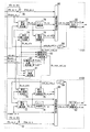
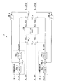
制御ユニット50は、上記の如き、ステップS9の電動車両制御演算処理を実行するための機能として、図12のブロック図で示す機能を備えている。図12に示す例では、制御ユニット50は、前輪3の制御を行う前輪制御部1101と、後輪4の制御を行う後輪制御部1102とを含んでいる。なお、前輪制御部1101と、後輪制御部1102とは、入力される情報が異なるだけであり、同一の動作を行う。
As described above, the
すなわち、制御ユニット50は、基体傾斜角度計測値θb_xy_sと基体傾斜角度目標値θb_xy_objとの偏差である基体傾斜角度偏差計測値θbe_xy_sを算出する偏差演算部70と、前記電動車両系重心点の移動速度である重心速度Vb_xyの観測値としての重心速度推定値Vb_xy_sを算出する重心速度算出部72と、乗員等による電動車両1の操縦操作(電動車両1に推進力を付加する操作)によって要求されていると推定される上記重心速度Vb_xyの要求値としての要求重心速度Vb_xy_aimを生成する要求重心速度生成部74と、これらの重心速度推定値Vb_xy_s及び要求重心速度Vb_xy_aimから、電動モータ31R,31Lの回転角速度の許容範囲に応じた制限を加味して、重心速度Vb_xyの目標値としての制御用目標重心速度Vb_xy_mdfdを決定する重心速度制限部76と、後述する式(07x),(07y)のゲイン係数の値を調整するためのゲイン調整パラメータKr_xyを決定するゲイン調整部78と、リーン角度決定部91と、回転中心位置決定部92と、前後左右速度指令決定部93とを備える。
That is, the
制御ユニット50は、さらに、前記仮想車輪回転角速度指令ωw_xy_cmdを算出する姿勢制御演算部80と、この仮想車輪回転角速度指令ωw_xy_cmdを、右側の電動モータ31Rの速度指令ω_R_cmd(回転角速度の指令値)と左側の電動モータ31Lの速度指令ω_L_cmd(回転角速度の指令値)との組に変換するモータ指令演算部82とを備える。
The
なお、図12中の参照符号84を付したものは、姿勢制御演算部80が制御処理周期毎に算出する仮想車輪回転角速度指令ωw_xy_cmdを入力する遅延要素を示している。該遅延要素84は、各制御処理周期において、仮想車輪回転角速度指令ωw_xy_cmdの前回値ωw_xy_cmd_pを出力する。
The
前記ステップS9の電動車両制御演算処理では、これらの上記の各処理部の処理が以下に説明するように実行される。 In the electric vehicle control calculation process in step S9, the processes of the above-described respective processing units are executed as described below.
すなわち、制御ユニット50は、まず、偏差演算部70の処理と重心速度算出部72の処理とを実行する。
That is, the
偏差演算部70には、前記ステップS2で算出された基体傾斜角度計測値θb_xy_s(θb_x_s及びθb_y_s)と、前記ステップS5又はステップS7で設定された目標値θb_xy_obj(θb_x_obj及びθb_y_obj)とが入力される。そして、偏差演算部70は、θb_x_sからθb_x_objを減算することによって、Y軸周り方向の基体傾斜角度偏差計測値θbe_x_s(=θb_x_s−θb_x_obj)を算出すると共に、θb_y_sからθb_y_objを減算することによって、X軸周り方向の基体傾斜角度偏差計測値θbe_y_s(=θb_y_s−θb_y_obj)を算出する。
The
なお、偏差演算部70の処理は、ステップS9の電動車両制御演算処理の前に行なうようにしてもよい。例えば、前記ステップS5又は7の処理の中で、偏差演算部70の処理を実行してもよい。
In addition, you may make it perform the process of the
前記重心速度算出部72には、前記ステップS2で算出された基体傾斜角速度計測値θbdot_xy_s(θbdot_x_s及びθbdot_y_s)の今回値が入力されると共に、仮想車輪速度指令ωw_xy_cmdの前回値ωw_xy_cmd_p(ωw_x_cmd_p及びωw_y_cmd_p)が遅延要素84から入力される。そして、重心速度算出部72は、これらの入力値から、前記倒立振子モデルに基づく所定の演算式によって、重心速度推定値Vb_xy_s(Vb_x_s及びVb_y_s)を算出する。
具体的には、重心速度算出部72は、次式(05x),(05y)により、Vb_x_s及びVb_y_sをそれぞれ算出する。
The center-of-gravity
Specifically, the center-of-gravity
Vb_x_s=Rw_x・ωw_x_cmd_p+h_x・θbdot_x_s 式(05x)
Vb_y_s=Rw_y・ωw_y_cmd_p+h_y・θbdot_y_s 式(05y)
Vb_x_s = Rw_x · ωw_x_cmd_p + h_x · θbdot_x_s Formula (05x)
Vb_y_s = Rw_y · ωw_y_cmd_p + h_y · θbdot_y_s Formula (05y)
これらの式(05x),(05y)において、Rw_x,Rw_yは、前記したように、仮想車輪62_x,62_yのそれぞれの半径であり、これらの値は、あらかじめ設定された所定値である。また、h_x,h_yは、それぞれ倒立振子モデルの質点60_x,60_yの高さである。この場合、本実施形態では、電動車両系重心点の高さは、ほぼ一定に維持されるものとされる。そこで、h_x,h_yの値としては、それぞれ、あらかじめ設定された所定値が用いられる。補足すると、高さh_x,h_yは、前記ステップS6又は8において値を設定する定数パラメータに含まれるものである。 In these expressions (05x) and (05y), Rw_x and Rw_y are the radii of the virtual wheels 62_x and 62_y, respectively, and these values are predetermined values set in advance. H_x and h_y are the heights of the mass points 60_x and 60_y of the inverted pendulum model, respectively. In this case, in the present embodiment, the height of the electric vehicle system center-of-gravity point is maintained substantially constant. Therefore, predetermined values set in advance are used as the values of h_x and h_y, respectively. Supplementally, the heights h_x and h_y are included in the constant parameters whose values are set in step S6 or 8.
上記式(05x)の右辺の第1項は、仮想車輪62_xの速度指令の前回値ωw_x_cmd_pに対応する該仮想車輪62_xのX軸方向の移動速度であり、この移動速度は、車輪体5のX軸方向の実際の移動速度の現在値に相当するものである。また、式(05x)の右辺の第2項は、基体9がY軸周り方向にθbdot_x_sの傾斜角速度で傾動することに起因して生じる電動車両系重心点のX軸方向の移動速度(車輪体5に対する相対的な移動速度)の現在値に相当するものである。これらのことは、式(05y)についても同様である。 The first term on the right side of the above formula (05x) is the moving speed in the X-axis direction of the virtual wheel 62_x corresponding to the previous value ωw_x_cmd_p of the speed command of the virtual wheel 62_x. This corresponds to the current value of the actual movement speed in the axial direction. Further, the second term on the right side of the equation (05x) represents the movement speed in the X-axis direction of the electric vehicle system center-of-gravity point caused by the base body 9 tilting at an inclination angular velocity of θbdot_x_s around the Y-axis (wheel body). This is equivalent to the current value of the relative movement speed with respect to 5. The same applies to the formula (05y).
なお、前記ロータリーエンコーダ56R,56Lの出力を基に計測される電動モータ31R,31Lのそれぞれの回転角速度の計測値(今回値)の組を、仮想車輪62_x,62_yのそれぞれの回転角速度の組に変換し、それらの回転角速度を、式(05x)、(05y)のωw_x_cmd_p、ωw_y_cmd_pの代わりに用いてもよい。ただし、回転角速度の計測値に含まれるノイズの影響を排除する上では、目標値であるωw_x_cmd_p、ωw_y_cmd_pを使用することが有利である。
Note that a set of measured values (current values) of the respective rotational angular velocities of the
次に、制御ユニット50は、要求重心速度生成部74の処理とゲイン調整部78の処理とを実行する。この場合、要求重心速度生成部74及びゲイン調整部78には、それぞれ、重心速度算出部72で上記の如く算出された重心速度推定値Vb_xy_s(Vb_x_s及びVb_y_s)が入力される。
Next, the
そして、要求重心速度生成部74は、電動車両1の動作モードが搭乗モードである場合に、入力された重心速度推定値Vb_xy_s(Vb_x_s及びVb_y_s)と、コントローラ6で検出された傾きによる値、即ち速度目標値Vb_x_objを基に、要求重心速度V_xy_aim(V_x_aim,V_y_aim)を決定する。Vb_x_objの値は、コントローラ6で検出された傾きに応じて変化する値である。これにより、乗員Dは、コントローラ6を操作することによって電動車両1の速度を任意の速度に設定することができる。なお、本実施形態では、電動車両1の動作モードが自立モードである場合には、要求重心速度生成部74は、要求重心速度V_x_aim及びV_y_aimをいずれも“0”とする。
Then, when the operation mode of the
また、ゲイン調整部78は、入力された重心速度推定値Vb_xy_s(Vb_x_s及びVb_y_s)を基に、前記ゲイン調整パラメータKr_xy(Kr_x及びKr_y)を決定する。
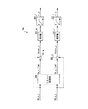
このゲイン調整部78の処理を図13及び図14を参照して以下に説明する。
図13に示すように、ゲイン調整部78は、入力された重心速度推定値Vb_x_s,Vb_y_sをリミット処理部86に入力する。このリミット処理部86では、重心速度推定値Vb_x_s,Vb_y_sに、電動モータ31R,31Lのそれぞれの回転角速度の許容範囲に応じた制限を適宜、加えることによって、出力値Vw_x_lim1,Vw_y_lim1を生成する。出力値Vw_x_lim1は、前記仮想車輪62_xのX軸方向の移動速度Vw_xの制限後の値、出力値Vw_y_lim1は、前記仮想車輪62_yのY軸方向の移動速度Vw_yの制限後の値としての意味を持つ。
Further, the
The processing of the
As shown in FIG. 13, the
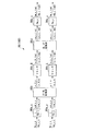
このリミット処理部86の処理を、図14を参照してさらに詳細に説明する。なお、図14中の括弧付きの参照符号は、後述する重心速度制限部76のリミット処理部104の処理を示すものであり、リミット処理部86の処理に関する説明では無視してよい。
The processing of the
リミット処理部86は、まず、重心速度推定値Vb_x_s,Vb_y_sをそれぞれ処理部86a_x,86a_yに入力する。処理部86a_xは、Vb_x_sを仮想車輪62_xの半径Rw_xで除算することによって、仮想車輪62_xのX軸方向の移動速度をVb_x_sに一致させたと仮定した場合の該仮想車輪62_xの回転角速度ωw_x_sを算出する。同様に、処理部86a_yは、仮想車輪62_yのY軸方向の移動速度をVb_y_sに一致させたと仮定した場合の該仮想車輪62_yの回転角速度ωw_y_s(=Vb_y_s/Rw_y)を算出する。
First, the
次いで、リミット処理部86は、ωw_x_s,ωw_y_sの組を、XY−RL変換部86bにより、電動モータ31Rの回転角速度ω_R_sと電動モータ31Lの回転角速度ω_L_sとの組に変換する。
Next, the
この変換は、本実施形態では、前記式(01a),(01b)のωw_x,ωw_y,ω_R,ω_Lをそれぞれ、ωw_x_s,ωw_y_s,ω_R_s,ω_L_sに置き換えて得られる連立方程式を、ω_R_s,ω_L_sを未知数として解くことにより行なわれる。 In this embodiment, in this embodiment, simultaneous equations obtained by replacing ωw_x, ωw_y, ω_R, and ω_L in the equations (01a) and (01b) with ωw_x_s, ωw_y_s, ω_R_s, and ω_L_s, respectively, and ω_R_s and ω_L_s are unknown. It is done by solving as
次いで、リミット処理部86は、XY−RL変換部86bの出力値ω_R_s,ω_L_sをそれぞれ、リミッタ86c_R,86c_Lに入力する。このとき、リミッタ86c_Rは、ω_R_sが、あらかじめ設定された所定値の上限値(>0)と下限値(<0)とを有する右モータ用許容範囲内に収まっている場合には、ω_R_sをそのまま出力値ω_R_lim1として出力する。また、リミッタ86c_Rは、ω_R_sが、右モータ用許容範囲から逸脱している場合には、該右モータ用許容範囲の上限値と下限値とのうちのω_R_sに近い方の境界値を出力値ω_R_lim1として出力する。これにより、リミッタ86c_Rの出力値ω_R_lim1は、右モータ用許容範囲内の値に制限される。
Next, the
同様に、リミッタ86c_Lは、ω_L_sが、あらかじめ設定された所定値の上限値(>0)と下限値(<0)とを有する左モータ用許容範囲内に収まっている場合には、ω_L_sをそのまま出力値ω_L_lim1として出力する。また、リミッタ86c_Lは、ω_L_sが、左モータ用許容範囲から逸脱している場合には、該左モータ用許容範囲の上限値と下限値とのうちのω_L_sに近い方の境界値を出力値ω_L_lim1として出力する。これにより、リミッタ86c_Lの出力値ω_L_lim1は、左モータ用許容範囲内の値に制限される。 Similarly, when the limiter 86c_L is within the allowable range for the left motor having a predetermined upper limit value (> 0) and lower limit value (<0), the limiter 86c_L keeps ω_L_s as it is. Output as output value ω_L_lim1. Further, when ω_L_s deviates from the left motor allowable range, the limiter 86c_L outputs the boundary value closer to ω_L_s between the upper limit value and the lower limit value of the left motor allowable range as the output value ω_L_lim1. Output as. As a result, the output value ω_L_lim1 of the limiter 86c_L is limited to a value within the left motor allowable range.
上記右モータ用許容範囲は右側の電動モータ31Rの回転角速度(絶対値)が高くなり過ぎないようにし、ひいては、電動モータ31Rが出力可能なトルクの最大値が低下するのを防止するために設定された許容範囲である。このことは、左モータ用許容範囲についても同様である。
The allowable range for the right motor is set so that the rotational angular velocity (absolute value) of the right
次いで、リミット処理部86は、リミッタ86c_R,86c_Lのそれぞれの出力値ω_R_lim1,ω_L_lim1の組を、RL−XY変換部86dにより、仮想車輪62_x,62_yのそれぞれの回転角速度ωw_x_lim1,ωw_y_lim1の組に変換する。
Next, the
この変換は、前記XY−RL変換部86bの変換処理の逆変換の処理である。この処理は、前記式(01a),(01b)のωw_x,ωw_y,ω_R,ω_Lをそれぞれ、ωw_x_lim1,ωw_y_lim1,ω_R_lim1,ω_L_lim1に置き換えて得られる連立方程式を、ωw_x_lim1,ωw_y_lim1を未知数として解くことにより行なわれる。
This conversion is a reverse conversion process of the conversion process of the XY-
次いで、リミット処理部86は、RL−XY変換部86dの出力値ωw_x_lim1,ωw_y_lim1をそれぞれ処理部86e_x,86e_yに入力する。処理部86e_xは、ωw_x_lim1に仮想車輪62_xの半径Rw_xを乗じることによって、ωw_x_lim1を仮想車輪62_xの移動速度Vw_x_lim1に変換する。同様に、処理部86e_yは、ωw_y_lim1を仮想車輪62_yの移動速度Vw_y_lim1(=ωw_y_lim1・Rw_y)に変換する。
Next, the
以上のリミット処理部86の処理によって、仮想車輪62_xのX軸方向の移動速度Vw_xと、仮想車輪62_yのY軸方向の移動速度Vw_yとをそれぞれ重心速度推定値Vb_x_s,Vb_y_sに一致させたと仮定した場合(換言すれば、車輪体5のX軸方向の移動速度とY軸方向の移動速度とをそれぞれ、Vb_x_s,Vb_y_sに一致させたと仮定した場合)に、それらの移動速度を実現するために必要な電動モータ31R,31Lのそれぞれの回転角速度ω_R_s,ω_L_sが、両方とも、許容範囲内に収まっている場合には、Vb_x_s,Vb_y_sにそれぞれ一致する出力値Vw_x_lim1,Vw_y_lim1の組がリミット処理部86から出力される。
It is assumed that the movement speed Vw_x of the virtual wheel 62_x in the X-axis direction and the movement speed Vw_y of the virtual wheel 62_y in the Y-axis direction are made to coincide with the center-of-gravity speed estimated values Vb_x_s and Vb_y_s, respectively, by the above processing of the
一方、電動モータ31R,31Lのそれぞれの回転角速度ω_R_s,ω_L_sの両方又は一方が許容範囲から逸脱している場合には、その両方又は一方の回転角速度が強制的に許容範囲内に制限された上で、その制限後の電動モータ31R,31Lのそれぞれの回転角速度ω_R_lim1,ω_L_lim1の組に対応する、X軸方向及びY軸方向の移動速度Vw_x_lim1,Vw_y_lim1の組がリミット処理部86から出力される。
On the other hand, when both or one of the rotational angular velocities ω_R_s and ω_L_s of the
従って、リミット処理部86は、その出力値Vw_x_lim1,Vw_y_lim1の組に対応する電動モータ31R,31Lのそれぞれの回転角速度が許容範囲を逸脱しないことを必須の必要条件として、その必要条件下で可能な限り、出力値Vw_x_lim1,Vw_y_lim1をそれぞれVb_x_s,Vb_y_sに一致させるように、出力値Vw_x_lim1,Vw_y_lim1の組を生成する。
Therefore, the
図13の説明に戻って、ゲイン調整部78は、次に、演算部88_x,88_yの処理を実行する。演算部88_xには、X軸方向の重心速度推定値Vb_x_sと、リミット処理部86の出力値Vw_x_lim1とが入力される。そして、演算部88_xは、Vw_x_lim1からVb_x_sを減算してなる値Vover_xを算出して出力する。また、演算部88_yには、Y軸方向の重心速度推定値Vb_y_sと、リミット処理部86の出力値Vw_y_lim1とが入力される。そして、演算部88_yは、Vw_y_lim1からVb_y_sを減算してなる値Vover_yを算出して出力する。
Returning to the description of FIG. 13, the
この場合、リミット処理部86での出力値Vw_x_lim1,Vw_y_lim1の強制的な制限が行なわれなかった場合には、Vw_x_lim1=Vb_x_s、Vw_y_lim1=Vb_y_sとなるので、演算部88_x,88_yのそれぞれの出力値Vover_x,Vover_yはいずれも“0”となる。
In this case, if the output values Vw_x_lim1 and Vw_y_lim1 are not forcibly limited by the
一方、リミット処理部86の出力値Vw_x_lim1,Vw_y_lim1が、入力値Vb_x_s,Vb_y_sに対して強制的な制限を施して生成された場合には、Vw_x_lim1のVb_x_sからの修正量(=Vw_x_lim1−Vb_x_s)と、Vw_y_lim1のVb_y_sからの修正量(=Vw_y_lim1−Vb_y_s)とがそれぞれ、演算部88_x,88_yから出力される。
On the other hand, when the output values Vw_x_lim1 and Vw_y_lim1 of the
次いで、ゲイン調整部78は、演算部88_xの出力値Vover_xを処理部90_x,92_xに順番に通すことによって、ゲイン調整パラメータKr_xを決定する。また、ゲイン調整部78は、演算部88_yの出力値Vover_yを処理部90_y,92_yに順番に通すことによって、ゲイン調整パラメータKr_yを決定する。なお、ゲイン調整パラメータKr_x,Kr_yは、いずれも“0”から“1”までの範囲内の値である。
Next, the
上記処理部90_xは、入力されるVover_xの絶対値を算出して出力する。また、処理部92_xは、その出力値Kr_xが入力値|Vover_x|に対して単調に増加し、且つ、飽和特性を有するようにKr_xを生成する。該飽和特性は、入力値がある程度大きくなると、入力値の増加に対する出力値の変化量が“0”になるか、もしくは、“0”に近づく特性である。 The processing unit 90_x calculates and outputs the absolute value of the input Vover_x. Further, the processing unit 92_x generates Kr_x so that the output value Kr_x monotonously increases with respect to the input value | Vover_x | and has a saturation characteristic. The saturation characteristic is a characteristic in which the change amount of the output value with respect to the increase of the input value becomes “0” or approaches “0” when the input value increases to some extent.
この場合、本実施形態では、処理部92_xは、入力値|Vover_x|があらかじめ設定された所定値以下である場合には、該入力値|Vover_x|に所定値の比例係数を乗じてなる値をKr_xとして出力する。また、処理部92_xは、入力値|Vover_x|が所定値よりも大きい場合には、“1”をKr_xとして出力する。なお、上記比例係数は、|Vover_x|が所定値に一致するときに、|Vover_x|と比例係数との積が“1”になるように設定されている。 In this case, in this embodiment, when the input value | Vover_x | is equal to or less than a predetermined value set in advance, the processing unit 92_x sets a value obtained by multiplying the input value | Vover_x | by a proportional coefficient of the predetermined value. Output as Kr_x. In addition, when the input value | Vover_x | is larger than a predetermined value, the processing unit 92_x outputs “1” as Kr_x. The proportional coefficient is set so that the product of | Vover_x | and the proportional coefficient is “1” when | Vover_x | matches a predetermined value.
また、処理部90_y,92_yの処理は、それぞれ上記した処理部90_x,92_xの処理と同様である。 The processing of the processing units 90_y and 92_y is the same as the processing of the above-described processing units 90_x and 92_x, respectively.
以上説明したゲイン調整部78の処理によって、リミット処理部86での出力値Vw_x_lim1,Vw_y_lim1の強制的な制限が行なわれなかった場合、すなわち、車輪体5のX軸方向及びY軸方向のそれぞれの移動速度Vw_x,Vw_yを、それぞれ、重心速度推定値Vb_x_s,Vb_y_sに一致させるように電動モータ31R,31Lを動作させても、電動モータ31R,31Lのそれぞれの回転角速度が許容範囲内に収まるような場合には、ゲイン調整パラメータKr_x,Kr_yはいずれも“0”に決定される。
When the output values Vw_x_lim1 and Vw_y_lim1 are not forcibly limited by the
一方、リミット処理部86の出力値Vw_x_lim1,Vw_y_lim1が、入力値Vb_x_s,Vb_y_sに対して強制的な制限を施して生成された場合、すなわち、車輪体5のX軸方向及びY軸方向のそれぞれの移動速度Vw_x,Vw_yを、それぞれ、重心速度推定値Vb_x_s,Vb_y_sに一致させるように電動モータ31R,31Lを動作させると、電動モータ31R,31Lのいずれかの回転角速度が許容範囲を逸脱してしまう場合(いずれかの回転角速度の絶対値が高くなり過ぎる場合)には、前記修正量Vover_x,Vover_yのそれぞれの絶対値に応じて、ゲイン調整パラメータKr_x,Kr_yの値がそれぞれ決定される。この場合、Kr_xは、“1”を上限値して、修正量Vx_overの絶対値が大きいほど、大きな値になるように決定される。このことは、Kr_yについても同様である。
On the other hand, when the output values Vw_x_lim1 and Vw_y_lim1 of the
図12の説明に戻って、制御ユニット50は、重心速度算出部72及び要求重心速度生成部74の処理を以上の如く実行した後、リーン角度決定部91と、回転中心位置決定部92と、前後左右速度指令決定部93との処理を実行する。
Returning to the description of FIG. 12, the
リーン角度決定部91は、電動車両1の傾きの目標値θb_xy_obj(θb_x_obj及びθb_y_obj)を決定する。ただし、本実施形態における電動車両1は二輪車であるため、前後方向の傾きの制御は不要であり、θb_x_obj=0である。なお、電動車両1の横方向の傾きの目標値θb_y_objは、コントローラ6で指示される、電動車両1の曲がりたい量を示す情報、即ち、旋回角速度目標値(例えば、コントローラ6が横方向または斜め方向に倒された量に基づいた値)ωb_aim_zと、要求重心速度生成部74から入力されたX方向の速度の目標値Vb_x_aimとで一意に決まる。具体的には式(10)によって算出することができる。なお、gは重力加速度である。
The lean angle determination unit 91 determines a target value θb_xy_obj (θb_x_obj and θb_y_obj) of the inclination of the
θb_y_obj=ωb_aim_z×Vb_x_aim/g (10) θb_y_obj = ωb_aim_z × Vb_x_aim / g (10)
リーン角度決定部91は、算出した電動車両1の横方向の傾きの目標値θb_y_obj(θb_x_obj=0である)を、偏差演算部70に入力する。
The lean angle determination unit 91 inputs the calculated target value θb_y_obj (θb_x_obj = 0) of the lateral inclination of the
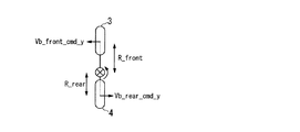
回転中心位置決定部92は、電動車両1の回転中心位置を決定する。図15は電動車両1の回転中心位置を示した概略図である。この図には、前輪3と、後輪4と、回転中心位置とが示されている。回転中心位置は、前輪3と後輪4との間にあり、電動車両1の加速度に応じて位置が変化する。この位置を前輪3からの距離と後輪4からの距離との比で表すことができる。本実施形態では、前輪3から回転中心位置までの距離と後輪4から回転中心位置までの距離の比をR_front:R_rearとする。なお、本実施形態ではR_front:R_rearを正規化し、R_front+R_rear=1の関係を満たすようにしている。
The rotation center
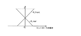
R_frontの値とR_rearの値とは、コントローラ6で検出された傾きによって一意に決まる。具体的には、R_frontの値とR_rearの値と、コントローラ6で検出された傾きとの関係は、図16に示す関係となる。図16は、R_frontの値とR_rearの値と、コントローラ6で検出された傾きとの関係を示した図である。図示する例では、コントローラ6で検出された傾きが0°であれば、R_frontの値とR_rearの値とはそれぞれ0.5である。また、コントローラ6で検出された傾きが正の方向に大きくなるにつれ、R_frontの値が大きくなり、それに伴いR_rearの値が小さくなる。また、コントローラ6で検出された傾きが負の方向に大きくなるにつれ、R_frontの値が小さくなり、それに伴いR_rearの値が大きくなる。なお上述したとおり、コントローラ6で検出された傾きが何れの値でも、R_front+R_rear=1である。 The value of R_front and the value of R_rear are uniquely determined by the inclination detected by the controller 6. Specifically, the relationship between the R_front value, the R_rear value, and the inclination detected by the controller 6 is as shown in FIG. FIG. 16 is a diagram illustrating the relationship between the R_front value, the R_rear value, and the inclination detected by the controller 6. In the example shown in the figure, if the inclination detected by the controller 6 is 0 °, the value of R_front and the value of R_rear are each 0.5. Further, as the inclination detected by the controller 6 increases in the positive direction, the value of R_front increases and accordingly the value of R_rear decreases. Further, as the inclination detected by the controller 6 increases in the negative direction, the value of R_front decreases, and the value of R_rear increases accordingly. As described above, R_front + R_rear = 1 regardless of the inclination detected by the controller 6.
回転中心位置決定部92は、決定した電動車両1の回転中心位置を示す情報、すなわちR_frontの値とR_rearの値とを前後左右速度指令決定部93に入力する。
The rotation center
前後左右速度指令決定部93は、前輪3の制御に用いる前輪3の要求重心速度Vb_front_cmd_xy(Vb_front_cmd_x及びVb_front_cmd_y)と、後輪4の制御に用いる後輪4の要求重心速度Vb_rear_xy(Vb_rear_cmd_x及びVb_rear_cmd_y)とを算出する。
The front / rear / left / right speed
なお、本実施形態では、ステップS1で、シート部12に着座した乗員Dが、コントローラ6を操作した場合、コントローラ6が検出した傾きの方向に電動車両1が移動するように、主輪5の移動動作が制御される。また、乗員Dがコントローラ6を操作することなく、右または左に体重をかけた場合、体重をかけた側、即ち、重心の移動方向に電動車両1が並進する。よって、前後左右速度指令決定部93は、この2つの動作に応じた処理を行う。
In the present embodiment, when the occupant D seated on the
はじめに、ステップS1で、シート部12に着座した乗員Dが、コントローラ6を傾けた場合における、前後左右速度指令決定部93の動作について説明する。
First, the operation of the front / rear / left / right speed
この場合、X方向の速度は、要求重心速度生成部74が算出した値と同様の値である。よって、回転中心位置決定部92は、Vb_front_cmd_xの値と、Vb_rear_cmd_xの値とを、要求重心速度生成部74から入力されたVb_x_aimの値と決定する。
In this case, the speed in the X direction is the same value as the value calculated by the required gravity center
また、前輪3のY方向の速度は式(11)を用いて算出することができる。
Further, the speed of the
Vb_front_cmd_y=R_front × ωb_aim_z 式(11) Vb_front_cmd_y = R_front × ωb_aim_z formula (11)
また、後輪4のY方向の速度は式(12)を用いて算出することができる。
Further, the speed of the
Vb_rear_cmd_y=−R_rear × ωb_aim_z 式(12) Vb_rear_cmd_y = −R_rear × ωb_aim_z Equation (12)
上述したように、前後左右速度指令決定部93は、前輪3の制御に用いる前輪3の要求重心速度Vb_front_cmd_xy(Vb_front_cmd_x及びVb_front_cmd_y)と、後輪4の制御に用いる後輪4の要求重心速度Vb_rear_xy(Vb_rear_cmd_x及びVb_rear_cmd_y)とを算出し、算出した結果を重心速度制御部76に入力する。
As described above, the front / rear / left / right speed
次に、ステップS1で、乗員Dがコントローラ6を操作することなく、右または左に体重をかけた場合における、前後左右速度指令決定部93の動作について説明する。この場合、前後左右速度指令決定部93は、ステップ1でコントローラ6の入力がされていないので前後の移動は行わない、すなわち左右方向への並進のみを行うと判断する。
Next, the operation of the front / rear / left / right speed
この場合、前後左右速度指令決定部93は、要求重心速度生成部74から入力されたVb_xy_aimの値を、Vb_front_cmd_xy(Vb_front_cmd_x及びVb_front_cmd_y)および、Vb_rear_xy(Vb_rear_cmd_x及びVb_rear_cmd_y)として、重心速度制御部76に入力する。これにより、前輪3と後輪4とが同一の動きを行うため、電動車両1は右方向あるいは左方向に並進することができる。
In this case, the front / rear / left / right speed
次に、制御ユニット50は、重心速度制限部76の処理を実行する。重心速度制御部76は、前輪3の制御と後輪4の制御とをそれぞれ行う。なお、前輪制御用の重心速度制御部76と後輪制御用の重心速度制御部76とが行う処理とは、前後左右速度指令決定部93から入力される値が異なるだけで、同一の処理である。
Next, the
この重心速度制限部76には、重心速度算出部72で算出された重心速度推定値Vb_xy_s(Vb_x_s及びVb_y_s)と、前後左右速度指令決定部93で決定された、前輪3の制御に用いる要求重心速度Vb_front_cmd_xy(Vb_front_cmd_x及びVb_front_cmd_y)と、後輪4の制御に用いる要求重心速度Vb_rear_xy(Vb_rear_cmd_x及びVb_rear_cmd_y)と、が入力される。そして、重心速度制限部76は、これらの入力値を使用して、図17のブロック図で示す処理を実行することによって、前輪3の制御に用いる制御用目標重心速度Vb_front_xy_mdfd(Vb_front_x_mdfd及びVb_front_y_mdfd)と、後輪4の制御に用いる制御用目標重心速度Vb_rear_xy_mdfd(Vb_rear_x_mdfd及びVb_rear_y_mdfd)とを決定する。
The center-of-gravity
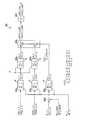
具体的には、重心速度制限部76は、まず、定常偏差算出部94_x,94_yの処理を実行する。なお、以下の処理は、これまでの説明と同様に、前輪3の制御と後輪4の制御とでそれぞれ行う。また、前輪3の制御と後輪4の制御とで処理の内容は同一のため、以下の説明においても前輪(_front)と後輪(_rear)とを分けずに説明する。
Specifically, the center-of-gravity
この場合、定常偏差算出部94_xには、X軸方向の重心速度推定値Vb_x_sが入力されると共に、X軸方向の制御用目標重心速度Vb_x_mdfdの前回値Vb_x_mdfd_pが遅延要素96_xを介して入力される。そして、定常偏差算出部94_xは、まず、入力されるVb_x_sが比例・微分補償要素(PD補償要素)94a_xに入力する。この比例・微分補償要素94_xは、その伝達関数が1+Kd・Sにより表される補償要素であり、入力されるVb_x_sと、その微分値(時間的変化率)に所定値の係数Kdを乗じてなる値とを加算し、その加算結果の値を出力する。 In this case, the steady-state deviation calculating unit 94_x receives the estimated center-of-gravity velocity value Vb_x_s in the X-axis direction and the previous value Vb_x_mdfd_p of the control target center-of-gravity velocity Vb_x_mdfd in the X-axis direction via the delay element 96_x. . The steady deviation calculating unit 94_x first inputs the input Vb_x_s to the proportional / differential compensation element (PD compensation element) 94a_x. The proportional / differential compensation element 94_x is a compensation element whose transfer function is represented by 1 + Kd · S, and is obtained by multiplying the input Vb_x_s and its differential value (time change rate) by a predetermined coefficient Kd. Add the value and output the result of the addition.
次いで、定常偏差算出部94_xは、入力されるVb_x_mdfd_pを、比例・微分補償要素94_xの出力値から減算してなる値を演算部94b_xにより算出した後、この演算部94b_xの出力値を、位相補償機能を有するローパスフィルタ94c_xに入力する。このローパスフィルタ94c_xは、伝達関数が(1+T2・S)/(1+T1・S)により表されるフィルタである。そして、定常偏差算出部94_xは、このローパスフィルタ94c_xの出力値Vb_x_prdを出力する。 Next, the steady deviation calculating unit 94_x calculates a value obtained by subtracting the input Vb_x_mdfd_p from the output value of the proportional / differential compensation element 94_x by the calculating unit 94b_x, and then outputs the output value of the calculating unit 94b_x to the phase compensation It inputs into the low-pass filter 94c_x which has a function. The low-pass filter 94c_x is a filter whose transfer function is represented by (1 + T2 · S) / (1 + T1 · S). The steady deviation calculating unit 94_x outputs the output value Vb_x_prd of the low-pass filter 94c_x.
また、定常偏差算出部94_yには、Y軸方向の重心速度推定値Vb_y_sが入力されると共に、Y軸方向の制御用目標重心速度Vb_y_mdfdの前回値Vb_y_mdfd_pが遅延要素96_yを介して入力される。 In addition, the steady-state deviation calculating unit 94_y receives the Y-axis centroid speed estimated value Vb_y_s and the previous value Vb_y_mdfd_p of the Y-axis control target centroid speed Vb_y_mdfd via the delay element 96_y.
そして、定常偏差算出部94_yは、上記した定常偏差算出部94_xと同様に、比例・微分補償要素94a_y、演算部94b_y及びローパスフィルタ94c_yの処理を順次実行し、ローパスフィルタ94c_yの出力値Vb_y_prdを出力する。 Then, similarly to the above-described steady deviation calculation unit 94_x, the steady deviation calculation unit 94_y sequentially executes the processing of the proportional / differential compensation element 94a_y, the calculation unit 94b_y, and the low-pass filter 94c_y, and outputs the output value Vb_y_prd of the low-pass filter 94c_y. To do.
ここで、定常偏差算出部94_xの出力値Vb_x_prdは、Y軸方向から見た電動車両系重心点の現在の運動状態(換言すればY軸方向から見た倒立振子モデルの質点60_xの運動状態)から推測される、将来のX軸方向の重心速度推定値の収束予測値の制御用目標重心速度Vb_x_mdfdに対する定常偏差としての意味を持つものである。同様に、定常偏差算出部94_y出力値Vb_y_prdは、X軸方向から見た電動車両系重心点の現在の運動状態(換言すればX軸方向から見た倒立振子モデルの質点60_yの運動状態)から推測される、将来のY軸方向の重心速度推定値の収束予測値の制御用目標重心速度Vb_y_mdfdに対する定常偏差としての意味を持つものである。以降、定常偏差算出部94_x,94_yのそれぞれの出力値Vb_x_prd,Vb_y_prdを重心速度定常偏差予測値という。 Here, the output value Vb_x_prd of the steady deviation calculating unit 94_x is the current motion state of the electric vehicle system center of gravity point viewed from the Y-axis direction (in other words, the motion state of the mass point 60_x of the inverted pendulum model viewed from the Y-axis direction). From the above, the convergence predicted value of the estimated gravity center speed value in the X-axis direction in the future has a meaning as a steady deviation with respect to the target gravity center speed Vb_x_mdfd for control. Similarly, the steady deviation calculating unit 94_y output value Vb_y_prd is derived from the current motion state of the electric vehicle system center of gravity point viewed from the X-axis direction (in other words, the motion state of the mass point 60_y of the inverted pendulum model viewed from the X-axis direction). It has a meaning as a steady deviation with respect to the control target center-of-gravity speed Vb_y_mdfd of the estimated predicted convergence value of the future center-of-gravity speed estimated value in the Y-axis direction. Hereinafter, the respective output values Vb_x_prd and Vb_y_prd of the steady deviation calculation units 94_x and 94_y are referred to as center-of-gravity velocity steady deviation prediction values.
重心速度制限部76は、上記の如く定常偏差算出部94_x,94_yの処理を実行した後、定常偏差算出部94_xの出力値Vb_x_prdに要求重心速度Vb_x_aimを加算する処理と、定常偏差算出部94_yの出力値Vb_y_prdに要求重心速度Vb_y_aimを加算する処理とをそれぞれ、演算部98_x,98_yにより実行する。
The center-of-
従って、演算部98_xの出力値Vb_x_tは、X軸方向の重心速度定常偏差予測値Vb_x_prdに、X軸方向の要求重心速度Vb_x_aimを付加した速度となる。同様に、演算部98_yの出力値Vb_y_tは、Y軸方向の重心速度定常偏差予測値Vb_y_prdに、Y軸方向の要求重心速度Vb_y_aimを付加した速度となる。 Therefore, the output value Vb_x_t of the calculation unit 98_x is a speed obtained by adding the required center-of-gravity speed Vb_x_aim in the X-axis direction to the center-of-gravity speed steady deviation predicted value Vb_x_prd in the X-axis direction. Similarly, the output value Vb_y_t of the calculation unit 98_y is a speed obtained by adding the requested center-of-gravity speed Vb_y_aim in the Y-axis direction to the center-of-gravity speed steady-state deviation predicted value Vb_y_prd in the Y-axis direction.
なお、電動車両1の動作モードが自立モードである場合等、X軸方向の要求重心速度Vb_x_aimが“0”である場合には、X軸方向の重心速度定常偏差予測値Vb_x_prdがそのまま、演算部98_xの出力値Vb_x_tとなる。同様に、Y軸方向の要求重心速度Vb_y_aimが“0”である場合には、Y軸方向の重心速度定常偏差予測値Vb_y_prdがそのまま、演算部98_yの出力値Vb_y_tとなる。
Note that when the required center of gravity speed Vb_x_aim in the X-axis direction is “0”, such as when the operation mode of the
次いで、重心速度制限部76は、演算部98_x,98_yのそれぞれの出力値Vb_x_t,Vb_y_tを、リミット処理部100に入力する。このリミット処理部100の処理は、前記したゲイン調整部78のリミット処理部86の処理と同じである。この場合、図14に括弧付きに参照符号で示す如く、リミット処理部100の各処理部の入力値及び出力値だけがリミット処理部86と相違する。
Next, the center-of-gravity
具体的には、リミット処理部100では、前記仮想車輪62_x,62_yのそれぞれの移動速度Vw_x,Vw_yを、Vb_x_t,Vb_y_tにそれぞれ一致させたと仮定した場合の各仮想車輪62_x,62_yの回転角速度ωw_x_t,ωw_y_tがそれぞれ処理部86a_x,86a_yにより算出される。そして、この回転角速度ωw_x_t,ωw_y_tの組が、XY−RL変換部86bにより、電動モータ31R,31Lの回転角速度ω_R_t,ω_L_tの組に変換される。
Specifically, in the
さらに、これらの回転角速度ω_R_t,ω_L_tが、リミッタ86c_R,86c_Lによって、それぞれ、右モータ用許容範囲内の値と左モータ用許容範囲内の値とに制限される。そして、この制限処理後の値ω_R_lim2,ω_L_lim2が、RL−XY変換部86dによって、仮想車輪62_x,62_yの回転角速度ωw_x_lim2,ωw_y_lim2に変換される。
Further, these rotational angular velocities ω_R_t and ω_L_t are limited by the limiters 86c_R and 86c_L to values within the allowable range for the right motor and values within the allowable range for the left motor, respectively. Then, the values ω_R_lim2 and ω_L_lim2 after the restriction process are converted into the rotational angular velocities ωw_x_lim2 and ωw_y_lim2 of the virtual wheels 62_x and 62_y by the RL-
次いで、この各回転角速度ωw_x_lim2,ωw_y_lim2に対応する各仮想車輪62_x,62_yの移動速度Vw_x_lim2,Vw_y_lim2がそれぞれ処理部86e_x,86e_yによって算出され、これらの移動速度Vw_x_lim2,Vw_y_lim2がリミット処理部100から出力される。
Next, the moving speeds Vw_x_lim2 and Vw_y_lim2 of the virtual wheels 62_x and 62_y corresponding to the rotational angular velocities ωw_x_lim2 and ωw_y_lim2 are calculated by the processing units 86e_x and 86e_y, respectively, and the moving speeds Vw_x_lim2 and Vw_y_lim2 are output from the
以上のリミット処理部100の処理によって、リミット処理部100は、リミット処理部86と同様に、その出力値Vw_x_lim2,Vw_y_lim2の組に対応する電動モータ31R,31Lのそれぞれの回転角速度が許容範囲を逸脱しないことを必須の必要条件として、その必要条件下で可能な限り、出力値Vw_x_lim2,Vw_y_lim2をそれぞれVb_x_t,Vb_y_tに一致させるように、出力値Vw_x_lim2,Vw_y_lim2の組を生成する。
By the above processing of the
なお、リミット処理部100における右モータ用及び左モータ用の各許容範囲は、リミット処理部86における各許容範囲と同一である必要はなく、互いに異なる許容範囲に設定されていてもよい。
Note that the permissible ranges for the right motor and the left motor in the
図17の説明に戻って、重心速度制限部76は、次に、演算部102_x,102_yの処理を実行することによって、それぞれ制御用目標重心速度Vb_x_mdfd,Vb_y_mdfdを算出する。この場合、演算部102_xは、リミット処理部100の出力値Vw_x_lim2から、X軸方向の重心速度定常偏差予測値Vb_x_prdを減算してなる値をX軸方向の制御用目標重心速度Vb_x_mdfdとして算出する。同様に、演算部102_yは、リミット処理部100の出力値Vw_y_lim2から、Y軸方向の重心速度定常偏差予測値Vb_y_prdを減算してなる値をY軸方向の制御用目標重心速度Vb_y_mdfdとして算出する。
Returning to the description of FIG. 17, the center-of-gravity
以上のようにして決定される制御用目標重心速度Vb_x_mdfd,Vb_y_mdfdは、リミット処理部100での出力値V_x_lim2,V_y_lim2の強制的な制限が行なわれなかった場合、すなわち、車輪体5のX軸方向及びY軸方向のそれぞれの移動速度を、それぞれ、演算部98_xの出力値Vb_x_tと演算部98_yの出力値Vb_y_tとに一致させるように電動モータ31R,31Lを動作させても、電動モータ31R,31Lのそれぞれの回転角速度が許容範囲内に収まるような場合には、要求重心速度Vb_x_aim,Vb_y_aimがそれぞれ、そのまま、制御用目標重心速度Vb_x_mdfd,Vb_y_mdfdとして決定される。
The control target center-of-gravity velocities Vb_x_mdfd and Vb_y_mdfd determined as described above are obtained when the output values V_x_lim2 and V_y_lim2 in the
なお、この場合、X軸方向の要求重心速度Vb_x_aimが“0”であれば、X軸方向の制御用目標重心速度Vb_x_mdfdも“0”となり、Y軸方向の要求重心速度Vb_y_aimが“0”であれば、Y軸方向の制御用目標重心速度Vb_y_mdfdも“0”となる。 In this case, if the required center-of-gravity speed Vb_x_aim in the X-axis direction is “0”, the control target center-of-gravity speed Vb_x_mdfd in the X-axis direction is also “0”, and the required center-of-gravity speed Vb_y_aim in the Y-axis direction is “0”. If there is, the control target center-of-gravity velocity Vb_y_mdfd in the Y-axis direction is also “0”.
一方、リミット処理部100の出力値Vw_x_lim2,Vw_y_lim2が、入力値Vb_x_t,Vb_y_tに対して強制的な制限を施して生成された場合、すなわち、車輪体5のX軸方向及びY軸方向のそれぞれの移動速度を、それぞれ、演算部98_xの出力値Vb_x_tと演算部98_yの出力値Vb_y_tとに一致させるように電動モータ31R,31Lを動作させると、電動モータ31R,31Lのいずれかの回転角速度が許容範囲を逸脱してしまう場合(いずれかの回転角速度の絶対値が高くなり過ぎる場合)には、X軸方向については、リミット処理部100の出力値Vw_x_lim2の入力値Vb_x_tからの修正量(=Vw_x_lim2−Vb_x_t)だけ、要求重心速度Vb_x_aimを補正してなる値(当該修正量をVb_x_aimに加算した値)が、X軸方向の制御用目標重心速度Vb_x_mdfdとして決定される。
On the other hand, when the output values Vw_x_lim2 and Vw_y_lim2 of the
また、Y軸方向については、リミット処理部100の出力値Vw_y_lim2の入力値Vb_y_tからの修正量(=Vw_y_lim2−Vb_y_t)だけ、要求重心速度Vb_y_aimを補正してなる値(当該修正量をVb_y_aimに加算した値)が、Y軸方向の制御用目標重心速度Vb_y_mdfdとして決定される。 For the Y-axis direction, a value obtained by correcting the requested center-of-gravity velocity Vb_y_aim by the correction amount (= Vw_y_lim2-Vb_y_t) from the input value Vb_y_t of the output value Vw_y_lim2 of the limit processing unit 100 (the correction amount is added to Vb_y_aim) Is determined as the control target center-of-gravity velocity Vb_y_mdfd in the Y-axis direction.
この場合において、例えばX軸方向の速度に関し、要求重心速度Vb_x_aimが“0”でない場合には、制御用目標重心速度Vb_x_mdfdは、要求重心速度Vb_x_aimよりも“0”に近づくか、もしくは、要求重心速度Vb_x_aimと逆向きの速度となる。また、要求重心速度Vb_x_aimが“0”である場合には、制御用目標重心速度Vb_x_mdfdは、定常偏差算出部94_xが出力するX軸方向の重心速度定常偏差予測値Vb_x_prdと逆向きの速度となる。これらのことは、Y軸方向の速度に関しても同様である。
以上が、重心速度制限部76の処理である。
In this case, for example, regarding the speed in the X-axis direction, if the requested center-of-gravity speed Vb_x_aim is not “0”, the control target center-of-gravity speed Vb_x_mdfd is closer to “0” than the requested center-of-gravity speed Vb_x_aim or The speed is opposite to the speed Vb_x_aim. When the required center-of-gravity speed Vb_x_aim is “0”, the control target center-of-gravity speed Vb_x_mdfd is a speed opposite to the X-axis center of gravity speed steady deviation predicted value Vb_x_prd output by the steady deviation calculating unit 94_x. . The same applies to the velocity in the Y-axis direction.
The above is the process of the gravity center
図12の説明に戻って、制御ユニット50は、以上の如く重心速度算出部72、重心速度制限部76、ゲイン調整部78の処理を実行した後、次に、姿勢制御演算部80の処理を実行する。
Returning to the description of FIG. 12, the
この姿勢制御演算部80の処理を、以下に図18を参照して説明する。なお、図18において、括弧を付していない参照符号は、X軸方向に輪転する仮想車輪62_xの回転角速度の目標値である前記仮想車輪回転角速度指令ωw_x_comを決定する処理に係わる参照符号であり、括弧付きの参照符合は、Y軸方向に輪転する仮想車輪62_yの回転角速度の目標値である前記仮想車輪回転角速度指令ωw_y_comを決定する処理に係わる参照符号である。
The processing of the attitude
姿勢制御演算部80には、偏差演算部70で算出された基体傾斜角度偏差計測値θbe_xy_sと、前記ステップS2で算出された基体傾斜角速度計測値θbdot_xy_sと、重心速度算出部72で算出された重心速度推定値Vb_xy_sと、重心速度制限部76で算出された目標重心速度Vb_xy_cmdと、ゲイン調整部78で算出されたゲイン調整パラメータKr_xyとが入力される。
The posture
そして、姿勢制御演算部80は、まず、これらの入力値を用いて、次式(07x),(07y)により、仮想車輪回転角加速度指令ωdotw_xy_comを算出する。
Then, the attitude
ωwdot_x_cmd=K1_x・θbe_x_s+K2_x・θbdot_x_s
+K3_x・(Vb_x_s−Vb_x_mdfd) 式(07x)
ωwdot_y_cmd=K1_y・θbe_y_s+K2_y・θbdot_y_s
+K3_y・(Vb_y_s−Vb_y_mdfd) 式(07y)
ωwdot_x_cmd = K1_x ・ θbe_x_s + K2_x ・ θbdot_x_s
+ K3_x · (Vb_x_s−Vb_x_mdfd) Formula (07x)
ωwdot_y_cmd = K1_y ・ θbe_y_s + K2_y ・ θbdot_y_s
+ K3_y · (Vb_y_s−Vb_y_mdfd) Formula (07y)
従って、本実施形態では、Y軸方向から見た倒立振子モデルの質点60_xの運動(ひいては、Y軸方向から見た電動車両系重心点の運動)を制御するための操作量(制御入力)としての仮想車輪回転角加速度指令ωdotw_x_comと、X軸方向から見た倒立振子モデルの質点60_yの運動(ひいては、X軸方向から見た電動車両系重心点の運動)を制御するための操作量(制御入力)としての仮想車輪回転角加速度指令ωdotw_y_comとは、それぞれ、3つの操作量成分(式(07x),(07y)の右辺の3つの項)を加え合わせることによって決定される。 Therefore, in the present embodiment, as an operation amount (control input) for controlling the motion of the mass point 60_x of the inverted pendulum model viewed from the Y-axis direction (and hence the motion of the electric vehicle system center-of-gravity point viewed from the Y-axis direction). Virtual wheel rotation angular acceleration command ωdotw_x_com and the amount of operation (control) for controlling the motion of the mass 60_y of the inverted pendulum model viewed from the X-axis direction (and hence the motion of the electric vehicle system center of gravity viewed from the X-axis direction) The virtual wheel rotation angular acceleration command ωdotw_y_com as an input is determined by adding three operation amount components (three terms on the right side of equations (07x) and (07y)).
この場合、式(07x)における各操作量成分に係わるゲイン係数K1_x,K2_x,K3_xは、ゲイン調整パラメータKr_xに応じて可変的に設定され、式(07y)における各操作量成分に係わるゲイン係数K1_y,K2_y,K3_yは、ゲイン調整パラメータKr_yに応じて可変的に設定される。以降、式(07x)におけるゲイン係数K1_x,K2_x,K3_xのそれぞれを第1ゲイン係数K1_x、第2ゲイン係数K2_x、第3ゲイン係数K3_xということがある。このことは、式(07y)におけるゲイン係数K1_y,K2_y,K3_yについても同様とする。 In this case, the gain coefficients K1_x, K2_x, and K3_x related to each manipulated variable component in Expression (07x) are variably set according to the gain adjustment parameter Kr_x, and the gain coefficient K1_y related to each manipulated variable component in Expression (07y). , K2_y, K3_y are variably set according to the gain adjustment parameter Kr_y. Hereinafter, the gain coefficients K1_x, K2_x, and K3_x in Expression (07x) may be referred to as a first gain coefficient K1_x, a second gain coefficient K2_x, and a third gain coefficient K3_x, respectively. The same applies to the gain coefficients K1_y, K2_y, and K3_y in the equation (07y).
式(07x)における第iゲイン係数Ki_x(i=1,2,3)と、式(07y)における第iゲイン係数Ki_y(i=1,2,3)とは、図18中にただし書きで示した如く、次式(09x)、(09y)により、ゲイン調整パラメータKr_x,Kr_yに応じて決定される。 The i-th gain coefficient Ki_x (i = 1, 2, 3) in the expression (07x) and the i-th gain coefficient Ki_y (i = 1, 2, 3) in the expression (07y) are shown in FIG. As described above, the gain adjustment parameters Kr_x and Kr_y are determined according to the following equations (09x) and (09y).
Ki_x=(1−Kr_x)・Ki_a_x+Kr_x・Ki_b_x ……式(09x)
Ki_y=(1−Kr_y)・Ki_a_y+Kr_y・Ki_b_y ……式(09y)
(i=1,2,3)
Ki_x = (1−Kr_x) · Ki_a_x + Kr_x · Ki_b_x Equation (09x)
Ki_y = (1−Kr_y) · Ki_a_y + Kr_y · Ki_b_y ...... Formula (09y)
(I = 1, 2, 3)
ここで、式(09x)におけるKi_a_x、Ki_b_xは、それぞれ、第iゲイン係数Ki_xの最小側(“0”に近い側)のゲイン係数値、最大側(“0”から離れる側)のゲイン係数値としてあらかじめ設定された定数値である。このことは、式(09y)におけるKi_a_y、Ki_b_yについても同様である。 Here, Ki_a_x and Ki_b_x in equation (09x) are the gain coefficient value on the minimum side (side closer to “0”) and the gain coefficient value on the maximum side (side away from “0”) of the i-th gain coefficient Ki_x, respectively. Is a preset constant value. The same applies to Ki_a_y and Ki_b_y in equation (09y).
従って、式(07x)の演算に用いる各第iゲイン係数Ki_x(i=1,2,3)は、それぞれに対応する定数値Ki_a_x、Ki_b_xの重み付き平均値として決定される。そして、この場合、Ki_a_x、Ki_b_xにそれぞれ掛かる重みが、ゲイン調整パラメータKr_xに応じて変化させられる。このため、Kr_x=0である場合には、Ki_x=Ki_a_xとなり、Kr_x=1である場合には、Ki_x=Ki_b_xとなる。そして、Kr_xが“0”から“1”に近づくに伴い、第iゲイン係数Ki_xはKi_a_xからKi_b_x近づいていく。 Accordingly, each i-th gain coefficient Ki_x (i = 1, 2, 3) used in the calculation of the expression (07x) is determined as a weighted average value of the corresponding constant values Ki_a_x and Ki_b_x. In this case, the weights applied to Ki_a_x and Ki_b_x are changed according to the gain adjustment parameter Kr_x. Therefore, when Kr_x = 0, Ki_x = Ki_a_x, and when Kr_x = 1, Ki_x = Ki_b_x. As Kr_x approaches “1” from “0”, the i-th gain coefficient Ki_x approaches Ki_b_x from Ki_a_x.
同様に、式(07y)の演算に用いる各第iゲイン係数Ki_y(i=1,2,3)は、それぞれに対応する定数値Ki_a_y、Ki_b_yの重み付き平均値として決定される。そして、この場合、Ki_a_y、Ki_b_yにそれぞれ掛かる重みが、ゲイン調整パラメータKr_yに応じて変化させられる。このため、Ki_xの場合と同様に、Kr_yの値が“0”から“1”の間で変化するに伴い、第iゲイン係数Ki_yの値が、Ki_a_yとKi_b_yとの間で変化する。 Similarly, each i-th gain coefficient Ki_y (i = 1, 2, 3) used for the calculation of Expression (07y) is determined as a weighted average value of the corresponding constant values Ki_a_y and Ki_b_y. In this case, the weights applied to Ki_a_y and Ki_b_y are changed according to the gain adjustment parameter Kr_y. Therefore, as in the case of Ki_x, as the value of Kr_y changes between “0” and “1”, the value of the i-th gain coefficient Ki_y changes between Ki_a_y and Ki_b_y.
補足すると、上記定数値Ki_a_x、Ki_b_x及びKi_a_y,Ki_b_y(i=1,2,3)は、前記ステップS6又は8において値が設定される定数パラメータに含まれるものである。 Supplementally, the constant values Ki_a_x, Ki_b_x and Ki_a_y, Ki_b_y (i = 1, 2, 3) are included in the constant parameters whose values are set in step S6 or 8.
姿勢制御演算部80は、上記の如く決定した第1〜第3ゲイン係数K1_x,K2_x,K3_xを用いて前記式(07x)の演算を行なうことで、X軸方向に輪転する仮想車輪62_xに係わる仮想車輪回転角加速度指令ωwdot_x_cmdを算出する。
The attitude
さらに詳細には、図18を参照して、姿勢制御演算部80は、基体傾斜角度偏差計測値θbe_x_sに第1ゲイン係数K1_xを乗じてなる操作量成分u1_xと、基体傾斜角速度計測値θbdot_x_sに第2ゲイン係数K2_xを乗じてなる操作量成分u2_xとをそれぞれ、処理部80a,80bで算出する。さらに、姿勢制御演算部80は、重心速度推定値Vb_x_sと制御用目標重心速度Vb_x_mdfdとの偏差(=Vb_x_s−Vb_x_mdfd)を演算部80dで算出し、この偏差に第3ゲイン係数K3_xを乗じてなる操作量成u3_xを処理部80cで算出する。そして、姿勢制御演算部80は、これらの操作量成分u1_x,u2_x,u3_xを演算部80eにて加え合わせることにより、仮想車輪回転角加速度指令ωwdot_x_comを算出する。
In more detail, with reference to FIG. 18, the posture
同様に、姿勢制御演算部80は、上記の如く決定した第1〜第3ゲイン係数K1_y,K2_y,K3_yを用いて前記式(07y)の演算を行なうことで、Y軸方向に輪転する仮想車輪62_yに係わる仮想車輪回転角加速度指令ωwdot_y_cmdを算出する。
Similarly, the attitude
この場合には、姿勢制御演算部80は、基体傾斜角度偏差計測値θbe_y_sに第1ゲイン係数K1_yを乗じてなる操作量成分u1_yと、基体傾斜角速度計測値θbdot_y_sに第2ゲイン係数K2_yを乗じてなる操作量成分u2_yとをそれぞれ、処理部80a,80bで算出する。さらに、姿勢制御演算部80は、重心速度推定値Vb_y_sと制御用目標重心速度Vb_y_mdfdとの偏差(=Vb_y_s−Vb_y_mdfd)を演算部80dで算出し、この偏差に第3ゲイン係数K3_yを乗じてなる操作量成分u3_yを処理部80cで算出する。そして、姿勢制御演算部80は、これらの操作量成分u1_y,u2_y,u3_yを演算部80eにて加え合わせることにより、仮想車輪回転角加速度指令ωwdot_y_comを算出する。
In this case, the posture
ここで、式(07x)の右辺の第1項(=第1操作量成分u1_x)及び第2項(=第2操作量成分u2_x)は、Y軸周り方向での基体傾斜角度偏差計測値θbe_x_sを、フィードバック制御則としてのPD則(比例・微分則)により“0”に収束させる(基体傾斜角度計測値θb_x_sを目標値θb_x_objに収束させる)ためのフィードバック操作量成分としての意味を持つ。 Here, the first term (= first manipulated variable component u1_x) and the second term (= second manipulated variable component u2_x) on the right side of the expression (07x) are measured values of the base body tilt angle deviation θbe_x_s in the direction around the Y axis. Is converged to “0” by the PD law (proportional / differential law) as a feedback control law (meaning that the measured base body tilt angle value θb_x_s converges to the target value θb_x_obj).
また、式(07x)の右辺の第3項(=第3操作量成分u3_x)は、重心速度推定値Vb_x_sと目標重心速度Vb_x_mdfdとの偏差をフィードバック制御則としての比例則により“0”に収束させる(Vb_x_sをVb_x_mdfdに収束させる)ためのフィードバック操作量成分としての意味を持つ。 In addition, the third term (= third manipulated variable component u3_x) on the right side of the expression (07x) converges to “0” by the proportional law as the feedback control law for the deviation between the center of gravity speed estimated value Vb_x_s and the target center of gravity speed Vb_x_mdfd. It has a meaning as a feedback manipulated variable component for causing Vb_x_s to converge to Vb_x_mdfd.
これらのことは、式(07y)の右辺の第1〜第3項(第1〜第3操作量成分u1_y,u2_y,u3_y)についても同様である。 The same applies to the first to third terms (first to third manipulated variable components u1_y, u2_y, u3_y) on the right side of Expression (07y).
姿勢制御演算部80は、上記の如く、仮想車輪回転角加速度指令ωwdot_x_com,ωwdot_y_comを算出した後、次に、これらのωwdot_x_com,ωwdot_y_comをそれぞれ積分器80fにより積分することによって、前記仮想車輪回転速度指令ωw_x_com,ωw_y_comを決定する。
以上が姿勢制御演算部80の処理の詳細である。
After calculating the virtual wheel rotation angular acceleration commands ωwdot_x_com and ωwdot_y_com as described above, the attitude
The above is the details of the processing of the attitude
補足すると、式(07x)の右辺の第3項を、Vb_x_sに応じた操作量成分(=K3_x・Vb_x_s)と、Vb_x_mdfdに応じた操作量成分(=−K3_x・Vb_x_mdfd)とに分離した式によって、仮想車輪回転角加速度指令ωdotw_x_comを算出するようにしてよい。同様に、式(07y)の右辺の第3項を、Vb_y_sに応じた操作量成分(=K3_y・Vb_y_s)と、Vb_y_mdfdに応じた操作量成分(=−K3_y・Vb_y_mdfd)とに分離した式によって、仮想車輪回転角加速度指令ωdotw_y_comを算出するようにしてよい。 Supplementally, the third term on the right side of the equation (07x) is divided into an operation amount component (= K3_x · Vb_x_s) corresponding to Vb_x_s and an operation amount component (= −K3_x · Vb_x_mdfd) corresponding to Vb_x_mdfd. The virtual wheel rotation angular acceleration command ωdotw_x_com may be calculated. Similarly, the third term on the right side of the equation (07y) is divided into an operation amount component (= K3_y · Vb_y_s) corresponding to Vb_y_s and an operation amount component (= −K3_y · Vb_y_mdfd) corresponding to Vb_y_mdfd. The virtual wheel rotation angular acceleration command ωdotw_y_com may be calculated.
また、本実施形態では、電動車両系重心点の挙動を制御するための操作量(制御入力)として、仮想車輪62_x,62_yの回転角加速度指令ωw_x_cmd,ωw_y_cmdを用いるようにしたが、例えば、仮想車輪62_x,62_yの駆動トルク、あるいは、この駆動トルクに各仮想車輪62_x,62_yの半径Rw_x,Rw_yを乗じてなる並進力(すなわち仮想車輪62_x,62_yと床面との間の摩擦力)を操作量として用いるようにしてもよい。 In the present embodiment, the rotation angular acceleration commands ωw_x_cmd and ωw_y_cmd of the virtual wheels 62_x and 62_y are used as the operation amount (control input) for controlling the behavior of the electric vehicle system center-of-gravity point. Manipulate the driving torque of the wheels 62_x and 62_y or a translational force obtained by multiplying the driving torque by the radii Rw_x and Rw_y of the virtual wheels 62_x and 62_y (that is, frictional forces between the virtual wheels 62_x and 62_y and the floor surface). It may be used as a quantity.
図12の説明に戻って、制御ユニット50は、次に、姿勢制御演算部80で上記の如く決定した仮想車輪回転速度指令ωw_x_com,ωw_y_comをモータ指令演算部82に入力し、該モータ指令演算部82の処理を実行することによって、電動モータ31Rの速度指令ω_R_comと電動モータ31Lの速度指令ω_L_comとを決定する。このモータ指令演算部82の処理は、前記リミット処理部86(図14参照)のXY−RL変換部86bの処理と同じである。
Returning to the description of FIG. 12, the
具体的には、モータ指令演算部82は、前記式(01a),(01b)のωw_x,ωw_y,ω_R,ω_Lをそれぞれ、ωw_x_com,ωw_y_com,ω_R_cmd,ω_L_cmdに置き換えて得られる連立方程式を、ω_R_cmd,ω_L_cmdを未知数として解くことによって、電動モータ31R,31Lのそれぞれの速度指令ω_R_com,ω_L_comを決定する。
以上により前記ステップS9の電動車両制御演算処理が完了する。
Specifically, the motor
Thus, the electric vehicle control calculation process in step S9 is completed.
以上説明した如く制御ユニット50が制御演算処理を実行することによって、前記搭乗モード及び自立モードのいずれの動作モードにおいても、基本的には、基体9の姿勢が、前記基体傾斜角度偏差計測値θbe_x_s,θbe_y_sの両方が“0”となる姿勢(以下、この姿勢を基本姿勢という)に保たれるように、換言すれば、電動車両系重心点(電動車両・乗員全体重心点又は電動車両単体重心点)の位置が、車輪体5の接地面のほぼ真上に位置する状態に保たれるように、操作量(制御入力)としての仮想車輪回転角加速度指令ωdotw_xy_comが決定される。より詳しく言えば、基体9の姿勢を前記基本姿勢に保ちつつ、電動車両系重心点の移動速度の推定値としての重心速度推定値Vb_xy_sを制御用目標重心速度Vb_xy_mdfdに収束させるように、仮想車輪回転角加速度指令ωdotw_xy_comが決定される。なお、制御用目標重心速度Vb_xy_mdfdは、通常は(詳しくは搭乗モードで乗員等が電動車両1の付加的な推進力を付与しない限り)、“0”である。この場合には、基体9の姿勢を前記基本姿勢に保ちつつ、電動車両系重心点がほぼ静止するように、仮想車輪回転角加速度指令ωdotw_xy_comが決定されることとなる。
As described above, the
そして、ωdotw_xy_comの各成分を積分してなる仮想車輪回転角速度指令ωw_xy_comを変換してなる電動モータ31R,31Lのそれぞれの回転角速度が、電動モータ31R,31Lの速度指令ω_R_cmd,ω_L_cmdとして決定される。さらに、その速度指令ω_R_cmd,ω_L_cmdに従って、各電動モータ31R,31Lの回転速度が制御される。ひいては車輪体5のX軸方向及びY軸方向のそれぞれの移動速度が、ωw_x_comに対応する仮想車輪62_xの移動速度と、ωw_y_comに対応する仮想車輪62_yの移動速度とに各々一致するように制御される。
Then, the rotational angular velocities of the
また、例えば、X軸周り方向で、実際の基体傾斜角度θb_yが目標値θb_y_objから右傾側にずれると、そのずれを解消すべく(θbe_y_sを“0”に収束させるべく)、車輪体5が右向きに移動する。同様に、実際のθb_yが目標値θb_y_objから左傾側にずれると、そのずれを解消すべく(θbe_y_sを“0”に収束させるべく)、車輪体5が左向きに移動する。
Further, for example, when the actual base body tilt angle θb_y shifts to the right tilt side from the target value θb_y_obj in the direction around the X axis, the
さらに、実際の基体傾斜角度θb_yが、目標値θb_y_objからずれると、θb_yのずれを解消するための車輪体5の左右方向の移動動作とが合成され、車輪体5がX軸方向及びY軸方向の合成方向(X軸方向及びY軸方向の両方向に対して傾斜した方向)に移動することとなる。
Further, when the actual base body inclination angle θb_y deviates from the target value θb_y_obj, the movement of the
このようにして、基体9が前記基本姿勢からY軸方向に傾くと、そのY軸方向に傾いた側に向かって、車輪体5が移動することとなる。従って、例えば前記搭乗モードにおいて、乗員が意図的にその上体をY軸方向に傾けると、そのY軸方向に傾けた側に、車輪体5が移動することとなる。
In this way, when the base body 9 is tilted from the basic posture in the Y-axis direction, the
なお、制御用目標重心速度Vb_x_mdfd,Vb_y_mdfdが“0”である場合には、基体9の姿勢が基本姿勢に収束すると、車輪体5の移動もほぼ停止する。また、例えば、基体9のY軸周り方向の傾斜角度θb_xを基本姿勢から傾いた一定の角度に維持すると、車輪体5のX軸方向の移動速度は、その角度に対応する一定の移動速度(制御用目標重心速度Vb_x_mdfdと一定の定常偏差を有する移動速度)に収束する。このことは、基体9のX軸周り方向の傾斜角度θb_yを基本姿勢から傾いた一定の角度に維持した場合も同様である。
When the control target center-of-gravity speeds Vb_x_mdfd and Vb_y_mdfd are “0”, the movement of the
また、例えば、前記要求重心速度生成部74で生成される要求重心速度Vb_x_aim,Vb_y_aimの両方が“0”となっている状況において、基体9の前記基本姿勢からの傾き量(基体傾斜角度偏差計測値θbe_x_s,θbe_y_s)が比較的大きくなり、それを解消し、もしくはその傾き量を維持するために必要な車輪体5のX軸方向及びY軸方向の一方又は両方の移動速度(これらの移動速度は、それぞれ、図17に示した前記重心速度定常偏差予測値Vb_x_prd、Vb_y_prdに相当する)が、電動モータ31R,31Lの一方又は両方の回転角速度を許容範囲から逸脱させてしまうような、過大な移動速度になるような状況では、該車輪体5の移動速度に対して逆向きとなる速度(詳しくは、Vw_x_lim2−Vb_x_prd及びVw_y_lim2−Vb_y_prd)が制御用目標重心速度Vb_x_mdfd,Vb_y_mdfdとして決定される。そして、制御入力を構成する操作量成分のうちの操作量成分u3_x,u3_yが、この制御用目標重心速度Vb_x_mdfd,Vb_y_mdfdに重心速度推定値Vb_x_s,Vb_y_sをそれぞれ収束させるように決定される。このため、基体9の前記基本姿勢からの傾き量が過大になるのを予防し、ひいては、電動モータ31R,31Lの一方又は両方の回転角速度が高速になり過ぎるのが防止される。
Further, for example, in a situation where both the required center-of-gravity speeds Vb_x_aim and Vb_y_aim generated by the required center-of-gravity
さらに、前記ゲイン調整部78では、重心速度推定値Vb_x_s,Vb_y_sの一方又は両方が大きくなり、ひいては、基体9の前記基本姿勢からの傾きを解消し、もしくはその傾き量を維持するために必要な車輪体5のX軸方向及びY軸方向の一方又は両方の移動速度が、電動モータ31R,31Lの一方又は両方の回転角速度を許容範囲から逸脱させてしまうような、過大な移動速度になる恐れがある状況では、その逸脱が顕著になるほど(詳しくは、図13に示すVover_x,Vover_yの絶対値が大きくなるほど)、前記ゲイン調整パラメータKr_x,Kr_yの一方又は両方が“0”から“1”に近づけられる。
Further, in the
この場合、前記式(09x)により算出される各第iゲイン係数Ki_x(i=1,2,3)は、Kr_xが“1”に近づくほど、最小側の定数値Ki_a_xから最大側の定数値Ki_b_xに近づく。このことは、前記式(09y)により算出される各第iゲイン係数Ki_y(i=1,2,3)についても同様である。 In this case, each i-th gain coefficient Ki_x (i = 1, 2, 3) calculated by the equation (09x) is set to the maximum constant value from the minimum constant value Ki_a_x as Kr_x approaches “1”. It approaches Ki_b_x. The same applies to each i-th gain coefficient Ki_y (i = 1, 2, 3) calculated by the equation (09y).
そして、上記ゲイン係数の絶対値が大きくなることによって、基体9の傾きの変化に対する操作量(仮想車輪回転角加速度指令ωdotw_x_cmd,ωdotw_y_cmd)の感度が高まる。従って、基体9の基本姿勢からの傾き量が大きくなろうとすると、それを素早く解消するように、車輪体5の移動速度が制御されることとなる。従って、基体9が基本姿勢から大きく傾くことが強めに抑制され、ひいては、車輪体5のX軸方向及びY軸方向の一方又は両方の移動速度が、電動モータ31R,31Lの一方又は両方の回転角速度を許容範囲から逸脱させてしまうような、過大な移動速度になるのを防止することができる。
As the absolute value of the gain coefficient increases, the sensitivity of the operation amount (virtual wheel rotation angular acceleration commands ωdotw_x_cmd, ωdotw_y_cmd) with respect to a change in the tilt of the base body 9 increases. Therefore, if the inclination amount of the base body 9 from the basic posture is increased, the moving speed of the
また、搭乗モードにおいて、要求重心速度生成部74が、乗員等の操縦操作による要求に応じて要求重心速度Vb_x_aim,Vb_y_aim(Vb_x_aim,Vb_y_aimの一方又は両方が“0”でない要求重心速度)を生成した場合には、電動モータ31R,31Lの一方又は両方の回転角速度が許容範囲を逸脱するような高速の回転角速度にならない限り(詳しくは図17に示すVw_x_lim2,Vw_y_lim2がVb_x_t,Vb_y_tにそれぞれ一致する限り)、要求重心速度Vb_x_aim,Vb_y_aimがそれぞれ前記制御用目標重心速度Vb_x_mdfd,Vb_y_mdfdとして決定される。このため、要求重心速度Vb_x_aim,Vb_y_aimを実現するように(実際の重心速度が要求重心速度Vb_x_aim,Vb_y_aimに近づくように)、車輪体5の移動速度が制御される。
Further, in the boarding mode, the requested center-of-gravity
上述したとおり、本実施形態によれば、コントローラ6は加減速の指令と旋回の指令とを検出する。また、傾斜センサ52は車体2の傾きを検出する。また、制御ユニット50は、コントローラ6が検出した加減速の指令に基づいて車体2の加減速の制御を行い、コントローラ6が検出した旋回の指令に基づいて車体2の旋回の制御を行い、傾斜センサ52が検出した車体2の傾きに基づいて車体2の横方向の並進を制御する。つまり、一方向(左右方向)のみ倒立振子型制御を行い、それとは異なる方向(前後方向)についてはコントローラの指示に従うよう制御する。これにより、電動車両1は、加減速の指令に応じた加減速や、旋回の指令に応じた旋回に加えて、基体の傾きに応じて並進することがことができる。
As described above, according to the present embodiment, the controller 6 detects an acceleration / deceleration command and a turn command. The
よって、シート部12に着座した乗員Dが、コントローラ6の操作を行った場合、コントローラ6が加減速および旋回の指令を検出し、検出した結果に基づいて電動車両1が移動するように、主輪5の移動動作が制御ユニット50によって制御される。また、乗員Dがコントローラ6を操作することなく、右または左に体重をかけた場合、体重をかけた側に電動車両1が並進する。これにより、電動車両1は、前輪3と後輪4とが同じ方向に駆動する並進と、前輪3と後輪4とがY軸方向に対して互いに逆向きに駆動する旋回とを行うことができる。
Therefore, when the occupant D seated on the
なお、本実施形態では、電動車両1が旋回を行う場合は、前輪3と後輪4とがY軸方向に対して互いに逆向きに駆動する例を示したが、これに限らない。例えば、前輪3と後輪4とのいずれかがY軸方向に駆動することで、電動車両1が旋回を行うようにしても良い。また、旋回指令値が所定値よりも高い場合は、その値に応じて左右方向の目標傾斜角度又は左右方向の目標移動速度を設定してもよい。これにより、急旋回が必要な場合、旋回の中心側への目標傾斜角度(θb_ obj)又は目標移動速度(θb_aim)を設定することで、素早く車両位置を変更することができる。
In the present embodiment, when the
また、本実施形態では、電動車両1が二輪車である例を示したが、これに限らない。例えば、電動車両1が三輪車や四輪車である等、複数の車輪を備えていても良い。また、電動車両1はコントローラとして、ハンドルとアクセルとブレーキなど、公知のコントローラを用いることができる。
Moreover, in this embodiment, although the example in which the
図19は、三輪車である電動車両1を前側から見た斜視図である。図示する例では、電動車両1は、2つの前輪1003と、1つの後輪1004を備えている。また、コントローラとして、ハンドル1005と、アクセル1006と、ブレーキ1007とを備えている。なお、後輪は2輪であっても構わない。
FIG. 19 is a perspective view of the
図20は、四輪車である電動車両1を前側から見た斜視図である。図示する例では、電動車両1は、2つの前輪1013と、2つの後輪1014とを備えている。
FIG. 20 is a perspective view of the
また、乗員Dが電動車両1に乗降し易いように、シート部がZ軸周りに90度回転するようにしても良い。図21は、シート部がZ軸周りに90度回転した電動車両1を後側から見た斜視図である。図示する例では、図19に示した電動車両1と比較して、図21に示す電動車両1が備えるシート部1002はZ軸周りに90度回転している。
Further, the seat portion may be rotated 90 degrees around the Z axis so that the occupant D can easily get on and off the
以上、図面を参照して本発明の実施形態について詳しく説明してきたが、具体的な構成は上述のものに限られることはなく、この発明の要旨を逸脱しない範囲内において様々な設計変更等をすることが可能である。 As described above, the embodiments of the present invention have been described in detail with reference to the drawings. However, the specific configuration is not limited to the above, and various design changes and the like can be made without departing from the scope of the present invention. Is possible.
1・・・電動車両、2・・・車体(基体)、3・・・前輪(第1の全方向駆動車輪)、4・・・後輪(第2の全方向駆動車輪)、6・・・コントローラ(加減速指令手段、旋回指令手段)、50・・・制御ユニット(制御部)、52・・・傾斜センサ(傾き検出手段)、54・・・荷重センサ、70・・・偏差演算部、72・・・重心速度算出部、74・・・要求重心速度生成部、76・・・重心速度制限部、78・・・ゲイン調整部、80・・・姿勢制御演算部、82・・・モータ指令演算部、84・・・遅延要素、91・・・リーン角度決定部、92・・・回転中心位置決定部、93・・・前後左右速度指令決定部、150・・・着座部
DESCRIPTION OF
Claims (5)
全方向に駆動可能な全方向駆動車輪を少なくとも1以上有する移動動作部と、
前記基体に取り付けられた着座部と、
を備えた電動車両であって、
加減速の指令を検出する加減速指令手段と、
旋回の指令を検出する旋回指令手段と、
前記基体の傾きを検出する傾き検出手段と、
前記加減速指令手段が検出した前記加減速の指令に基づいて前記基体の加減速の制御を行い、前記旋回指令手段が検出した前記旋回の指令に基づいて前記基体の旋回の制御を行い、前記加減速指令手段が前記加減速の指令を検出しておらず且つ前記旋回指令手段が前記旋回の指令を検出しておらず且つ前記傾き検出手段が前記基体の傾きを検出した場合、前記傾き検出手段が検出した前記基体の傾きに基づいて前記基体の並進を制御する制御部と、
を備えたことを特徴とする電動車両。 A substrate;
A moving operation unit having at least one or more omnidirectional driving wheels capable of being driven in all directions;
A seating portion attached to the base;
An electric vehicle comprising:
An acceleration / deceleration command means for detecting an acceleration / deceleration command;
A turn command means for detecting a turn command;
An inclination detecting means for detecting the inclination of the substrate;
The acceleration-deceleration command means on the basis of a command of the acceleration and deceleration detected and controls the acceleration and deceleration of the substrate, and controls the pivoting of the base body on the basis of a command of the pivoting said turning command means detects the If the acceleration / deceleration command means does not detect the acceleration / deceleration command, the turn command means does not detect the turn command, and the tilt detection means detects the tilt of the base, the tilt detection A control unit for controlling the translation of the base based on the inclination of the base detected by the means;
An electrically powered vehicle comprising:
前記基体に取り付けられ、全方向に駆動可能な第1の全方向駆動車輪と、
対称軸が前記第1の全方向駆動車輪の対称軸と平行になるように前記基体に取り付けられた第2の全方向駆動車輪と、
前記第1の全方向駆動車輪の車輪中心と前記第2の全方向駆動車輪の車輪中心とを結んだ直線が前後方向を規定するように取り付けられた着座部と、
を備えた電動車両であって、
加減速の指令を検出する加減速指令手段と、
旋回の指令を検出する旋回指令手段と、
前記基体の傾きを検出する傾き検出手段と、
前記加減速指令手段が検出した前記加減速の指令に基づいて前記基体の加減速の制御を行い、前記旋回指令手段が検出した前記旋回の指令に基づいて前記基体の旋回の制御を行い、前記加減速指令手段が前記加減速の指令を検出しておらず且つ前記旋回指令手段が前記旋回の指令を検出しておらず且つ前記傾き検出手段が前記基体の傾きを検出した場合、前記傾き検出手段が検出した前記基体の傾きに基づいて前記基体の並進を制御する制御部と、
を備えたことを特徴とする電動車両。 A substrate;
A first omnidirectional drive wheel attached to the substrate and capable of being driven in all directions;
A second omnidirectional drive wheel attached to the base such that an axis of symmetry is parallel to the axis of symmetry of the first omnidirectional drive wheel;
A seating portion attached so that a straight line connecting a wheel center of the first omnidirectional driving wheel and a wheel center of the second omnidirectional driving wheel defines a front-rear direction;
An electric vehicle comprising:
An acceleration / deceleration command means for detecting an acceleration / deceleration command;
A turn command means for detecting a turn command;
An inclination detecting means for detecting the inclination of the substrate;
The acceleration-deceleration command means on the basis of a command of the acceleration and deceleration detected and controls the acceleration and deceleration of the substrate, and controls the pivoting of the base body on the basis of a command of the pivoting said turning command means detects the If the acceleration / deceleration command means does not detect the acceleration / deceleration command, the turn command means does not detect the turn command, and the tilt detection means detects the tilt of the base, the tilt detection A control unit for controlling the translation of the base based on the inclination of the base detected by the means;
An electrically powered vehicle comprising:
ことを特徴とする請求項4に記載の電動車両。 The electric vehicle according to claim 4, wherein a front-rear direction of the seating portion and the straight line are parallel to each other.
Priority Applications (2)
| Application Number | Priority Date | Filing Date | Title |
|---|---|---|---|
| JP2009219761A JP5484845B2 (en) | 2009-09-24 | 2009-09-24 | Electric vehicle |
| US12/889,667 US8583302B2 (en) | 2009-09-24 | 2010-09-24 | Electric vehicle |
Applications Claiming Priority (1)
| Application Number | Priority Date | Filing Date | Title |
|---|---|---|---|
| JP2009219761A JP5484845B2 (en) | 2009-09-24 | 2009-09-24 | Electric vehicle |
Publications (2)
| Publication Number | Publication Date |
|---|---|
| JP2011068218A JP2011068218A (en) | 2011-04-07 |
| JP5484845B2 true JP5484845B2 (en) | 2014-05-07 |
Family
ID=43757352
Family Applications (1)
| Application Number | Title | Priority Date | Filing Date |
|---|---|---|---|
| JP2009219761A Expired - Fee Related JP5484845B2 (en) | 2009-09-24 | 2009-09-24 | Electric vehicle |
Country Status (2)
| Country | Link |
|---|---|
| US (1) | US8583302B2 (en) |
| JP (1) | JP5484845B2 (en) |
Families Citing this family (29)
| Publication number | Priority date | Publication date | Assignee | Title |
|---|---|---|---|---|
| US8353378B2 (en) * | 2009-09-18 | 2013-01-15 | Honda Motor Co., Ltd. | Frictional drive device and inverted pendulum type vehicle using the same |
| JP5398446B2 (en) * | 2009-09-18 | 2014-01-29 | 本田技研工業株式会社 | Drive device |
| JP5426681B2 (en) * | 2009-09-18 | 2014-02-26 | 本田技研工業株式会社 | Inverted pendulum type moving body |
| US8731758B2 (en) * | 2010-04-06 | 2014-05-20 | Toyota Jidosha Kabushiki Kaisha | Vehicle control apparatus, control method thereof, and control software |
| JP5741278B2 (en) * | 2011-07-26 | 2015-07-01 | 株式会社エクォス・リサーチ | vehicle |
| JP2013129414A (en) * | 2011-11-26 | 2013-07-04 | Honda Motor Co Ltd | Omnidirectional moving vehicle |
| JP5927031B2 (en) * | 2011-11-26 | 2016-05-25 | 本田技研工業株式会社 | Inverted pendulum type vehicle |
| JP5808289B2 (en) | 2012-05-14 | 2015-11-10 | 本田技研工業株式会社 | Inverted pendulum type vehicle |
| JP5921950B2 (en) * | 2012-05-14 | 2016-05-24 | 本田技研工業株式会社 | Inverted pendulum type vehicle |
| JP6081081B2 (en) | 2012-05-14 | 2017-02-15 | 本田技研工業株式会社 | Inverted pendulum type vehicle |
| JP5959927B2 (en) * | 2012-05-14 | 2016-08-02 | 本田技研工業株式会社 | Inverted pendulum type vehicle |
| JP5916520B2 (en) * | 2012-05-14 | 2016-05-11 | 本田技研工業株式会社 | Inverted pendulum type vehicle |
| JP5927032B2 (en) * | 2012-05-14 | 2016-05-25 | 本田技研工業株式会社 | Inverted pendulum type vehicle |
| JP5959928B2 (en) | 2012-05-14 | 2016-08-02 | 本田技研工業株式会社 | Inverted pendulum type vehicle |
| JP5945477B2 (en) * | 2012-08-31 | 2016-07-05 | 本田技研工業株式会社 | Inverted pendulum type vehicle and control method of inverted pendulum type vehicle |
| TWM445524U (en) | 2012-09-06 | 2013-01-21 | Tcv Ind Co Ltd | Wheeled walker |
| US9027678B1 (en) * | 2013-03-14 | 2015-05-12 | University Of South Florida | Omni-directional remote-controlled mobility apparatus |
| JP6095436B2 (en) * | 2013-03-27 | 2017-03-15 | 本田技研工業株式会社 | Inverted pendulum type vehicle |
| JP6062785B2 (en) | 2013-03-29 | 2017-01-18 | 本田技研工業株式会社 | Inverted pendulum type vehicle |
| JP6081271B2 (en) * | 2013-03-29 | 2017-02-15 | 本田技研工業株式会社 | Inverted pendulum type vehicle |
| JP6081270B2 (en) | 2013-03-29 | 2017-02-15 | 本田技研工業株式会社 | Inverted pendulum type vehicle |
| JP6111119B2 (en) | 2013-03-29 | 2017-04-05 | 本田技研工業株式会社 | Inverted pendulum type vehicle |
| JP6099483B2 (en) | 2013-05-31 | 2017-03-22 | 本田技研工業株式会社 | Inverted pendulum type vehicle |
| JP6099484B2 (en) | 2013-05-31 | 2017-03-22 | 本田技研工業株式会社 | Inverted pendulum type vehicle |
| JP6099485B2 (en) | 2013-05-31 | 2017-03-22 | 本田技研工業株式会社 | Inverted pendulum type vehicle |
| JP5962689B2 (en) * | 2014-02-14 | 2016-08-03 | トヨタ自動車株式会社 | Autonomous mobile body and failure determination method thereof |
| CN107943015B (en) | 2016-10-12 | 2022-07-15 | 福特环球技术公司 | Autonomous personal mobility system |
| JP6823664B2 (en) * | 2016-10-19 | 2021-02-03 | 川崎重工業株式会社 | Tire force estimation device and tire force estimation method |
| KR20210045207A (en) * | 2019-10-16 | 2021-04-26 | 현대자동차주식회사 | Omnidirectional wheel and three-wheeled vehicle using the same |
Family Cites Families (7)
| Publication number | Priority date | Publication date | Assignee | Title |
|---|---|---|---|---|
| US4413693A (en) * | 1981-03-27 | 1983-11-08 | Derby Sherwin L | Mobile chair |
| US7275607B2 (en) * | 1999-06-04 | 2007-10-02 | Deka Products Limited Partnership | Control of a personal transporter based on user position |
| JP4523244B2 (en) * | 2003-05-22 | 2010-08-11 | 独立行政法人科学技術振興機構 | Power-assisted mobile trolley |
| JP2006102387A (en) | 2004-10-08 | 2006-04-20 | Honda Motor Co Ltd | Small-size electric vehicle |
| JP4600223B2 (en) * | 2005-09-12 | 2010-12-15 | トヨタ自動車株式会社 | Running body and method of adjusting running body |
| US8240407B2 (en) * | 2007-05-16 | 2012-08-14 | Honda Motor Co., Ltd. | Omni-directional vehicle |
| JP4868243B2 (en) * | 2007-08-07 | 2012-02-01 | 関東自動車工業株式会社 | Three-wheel travel device |
-
2009
- 2009-09-24 JP JP2009219761A patent/JP5484845B2/en not_active Expired - Fee Related
-
2010
- 2010-09-24 US US12/889,667 patent/US8583302B2/en active Active
Also Published As
| Publication number | Publication date |
|---|---|
| US20110071715A1 (en) | 2011-03-24 |
| US8583302B2 (en) | 2013-11-12 |
| JP2011068218A (en) | 2011-04-07 |
Similar Documents
| Publication | Publication Date | Title |
|---|---|---|
| JP5484845B2 (en) | Electric vehicle | |
| JP5306474B2 (en) | Control device for inverted pendulum type vehicle | |
| JP5504272B2 (en) | Control device for inverted pendulum type vehicle | |
| JP5318216B2 (en) | Inverted pendulum type vehicle | |
| JP5404800B2 (en) | Inverted pendulum type vehicle | |
| JP5414801B2 (en) | Control device for inverted pendulum type vehicle | |
| JPWO2011033586A1 (en) | Control device for inverted pendulum type vehicle | |
| JP5306472B2 (en) | Control device for inverted pendulum type vehicle | |
| JP5414804B2 (en) | Control device for inverted pendulum type vehicle | |
| JP5330200B2 (en) | Control device for inverted pendulum type vehicle | |
| JP5414800B2 (en) | Control device for inverted pendulum type vehicle | |
| JP5355700B2 (en) | Inverted pendulum type moving body control device | |
| JP5379235B2 (en) | Control device for inverted pendulum type vehicle | |
| JP5430317B2 (en) | Control device for inverted pendulum type vehicle | |
| JP5436119B2 (en) | Inverted pendulum type moving body | |
| JP5303413B2 (en) | Inverted pendulum type moving body control device | |
| JP5355348B2 (en) | Control device for omnidirectional vehicle | |
| JP5306471B2 (en) | Control device for inverted pendulum type vehicle | |
| JP2011068216A (en) | Control device of omnidirectional moving vehicle | |
| JP5386283B2 (en) | Inverted pendulum type moving body, control device, and control method | |
| JP5330199B2 (en) | Control device for inverted pendulum type vehicle | |
| JP5330198B2 (en) | Control device for inverted pendulum type vehicle |
Legal Events
| Date | Code | Title | Description |
|---|---|---|---|
| A621 | Written request for application examination |
Free format text: JAPANESE INTERMEDIATE CODE: A621 Effective date: 20111124 |
|
| A521 | Request for written amendment filed |
Free format text: JAPANESE INTERMEDIATE CODE: A523 Effective date: 20120518 |
|
| A131 | Notification of reasons for refusal |
Free format text: JAPANESE INTERMEDIATE CODE: A131 Effective date: 20130528 |
|
| A977 | Report on retrieval |
Free format text: JAPANESE INTERMEDIATE CODE: A971007 Effective date: 20130531 |
|
| A521 | Request for written amendment filed |
Free format text: JAPANESE INTERMEDIATE CODE: A523 Effective date: 20130722 |
|
| TRDD | Decision of grant or rejection written | ||
| A01 | Written decision to grant a patent or to grant a registration (utility model) |
Free format text: JAPANESE INTERMEDIATE CODE: A01 Effective date: 20140204 |
|
| A61 | First payment of annual fees (during grant procedure) |
Free format text: JAPANESE INTERMEDIATE CODE: A61 Effective date: 20140219 |
|
| R150 | Certificate of patent or registration of utility model |
Ref document number: 5484845 Country of ref document: JP Free format text: JAPANESE INTERMEDIATE CODE: R150 |
|
| LAPS | Cancellation because of no payment of annual fees |