JP5483776B2 - Display mechanism part of an automatic applicator for insulin in particular - Google Patents
Display mechanism part of an automatic applicator for insulin in particular Download PDFInfo
- Publication number
- JP5483776B2 JP5483776B2 JP2012522043A JP2012522043A JP5483776B2 JP 5483776 B2 JP5483776 B2 JP 5483776B2 JP 2012522043 A JP2012522043 A JP 2012522043A JP 2012522043 A JP2012522043 A JP 2012522043A JP 5483776 B2 JP5483776 B2 JP 5483776B2
- Authority
- JP
- Japan
- Prior art keywords
- display
- outer cylinder
- display mechanism
- control nut
- drive
- Prior art date
- Legal status (The legal status is an assumption and is not a legal conclusion. Google has not performed a legal analysis and makes no representation as to the accuracy of the status listed.)
- Active
Links
Images


Classifications
-
- A—HUMAN NECESSITIES
- A61—MEDICAL OR VETERINARY SCIENCE; HYGIENE
- A61M—DEVICES FOR INTRODUCING MEDIA INTO, OR ONTO, THE BODY; DEVICES FOR TRANSDUCING BODY MEDIA OR FOR TAKING MEDIA FROM THE BODY; DEVICES FOR PRODUCING OR ENDING SLEEP OR STUPOR
- A61M5/00—Devices for bringing media into the body in a subcutaneous, intra-vascular or intramuscular way; Accessories therefor, e.g. filling or cleaning devices, arm-rests
- A61M5/178—Syringes
- A61M5/31—Details
-
- A—HUMAN NECESSITIES
- A61—MEDICAL OR VETERINARY SCIENCE; HYGIENE
- A61M—DEVICES FOR INTRODUCING MEDIA INTO, OR ONTO, THE BODY; DEVICES FOR TRANSDUCING BODY MEDIA OR FOR TAKING MEDIA FROM THE BODY; DEVICES FOR PRODUCING OR ENDING SLEEP OR STUPOR
- A61M5/00—Devices for bringing media into the body in a subcutaneous, intra-vascular or intramuscular way; Accessories therefor, e.g. filling or cleaning devices, arm-rests
- A61M5/178—Syringes
- A61M5/20—Automatic syringes, e.g. with automatically actuated piston rod, with automatic needle injection, filling automatically
-
- A—HUMAN NECESSITIES
- A61—MEDICAL OR VETERINARY SCIENCE; HYGIENE
- A61M—DEVICES FOR INTRODUCING MEDIA INTO, OR ONTO, THE BODY; DEVICES FOR TRANSDUCING BODY MEDIA OR FOR TAKING MEDIA FROM THE BODY; DEVICES FOR PRODUCING OR ENDING SLEEP OR STUPOR
- A61M5/00—Devices for bringing media into the body in a subcutaneous, intra-vascular or intramuscular way; Accessories therefor, e.g. filling or cleaning devices, arm-rests
- A61M5/178—Syringes
- A61M5/31—Details
- A61M5/3129—Syringe barrels
-
- A—HUMAN NECESSITIES
- A61—MEDICAL OR VETERINARY SCIENCE; HYGIENE
- A61M—DEVICES FOR INTRODUCING MEDIA INTO, OR ONTO, THE BODY; DEVICES FOR TRANSDUCING BODY MEDIA OR FOR TAKING MEDIA FROM THE BODY; DEVICES FOR PRODUCING OR ENDING SLEEP OR STUPOR
- A61M5/00—Devices for bringing media into the body in a subcutaneous, intra-vascular or intramuscular way; Accessories therefor, e.g. filling or cleaning devices, arm-rests
- A61M5/178—Syringes
- A61M5/31—Details
- A61M5/315—Pistons; Piston-rods; Guiding, blocking or restricting the movement of the rod or piston; Appliances on the rod for facilitating dosing ; Dosing mechanisms
- A61M5/31525—Dosing
- A61M5/31528—Dosing by means of rotational movements, e.g. screw-thread mechanisms
-
- A—HUMAN NECESSITIES
- A61—MEDICAL OR VETERINARY SCIENCE; HYGIENE
- A61M—DEVICES FOR INTRODUCING MEDIA INTO, OR ONTO, THE BODY; DEVICES FOR TRANSDUCING BODY MEDIA OR FOR TAKING MEDIA FROM THE BODY; DEVICES FOR PRODUCING OR ENDING SLEEP OR STUPOR
- A61M5/00—Devices for bringing media into the body in a subcutaneous, intra-vascular or intramuscular way; Accessories therefor, e.g. filling or cleaning devices, arm-rests
- A61M5/178—Syringes
- A61M5/31—Details
- A61M5/315—Pistons; Piston-rods; Guiding, blocking or restricting the movement of the rod or piston; Appliances on the rod for facilitating dosing ; Dosing mechanisms
- A61M5/31533—Dosing mechanisms, i.e. setting a dose
- A61M5/31535—Means improving security or handling thereof, e.g. blocking means, means preventing insufficient dosing, means allowing correction of overset dose
- A61M5/31543—Means improving security or handling thereof, e.g. blocking means, means preventing insufficient dosing, means allowing correction of overset dose piston rod reset means, i.e. means for causing or facilitating retraction of piston rod to its starting position during cartridge change
-
- A—HUMAN NECESSITIES
- A61—MEDICAL OR VETERINARY SCIENCE; HYGIENE
- A61M—DEVICES FOR INTRODUCING MEDIA INTO, OR ONTO, THE BODY; DEVICES FOR TRANSDUCING BODY MEDIA OR FOR TAKING MEDIA FROM THE BODY; DEVICES FOR PRODUCING OR ENDING SLEEP OR STUPOR
- A61M5/00—Devices for bringing media into the body in a subcutaneous, intra-vascular or intramuscular way; Accessories therefor, e.g. filling or cleaning devices, arm-rests
- A61M5/178—Syringes
- A61M5/31—Details
- A61M5/315—Pistons; Piston-rods; Guiding, blocking or restricting the movement of the rod or piston; Appliances on the rod for facilitating dosing ; Dosing mechanisms
- A61M5/31533—Dosing mechanisms, i.e. setting a dose
- A61M5/31545—Setting modes for dosing
- A61M5/31548—Mechanically operated dose setting member
- A61M5/3155—Mechanically operated dose setting member by rotational movement of dose setting member, e.g. during setting or filling of a syringe
-
- A—HUMAN NECESSITIES
- A61—MEDICAL OR VETERINARY SCIENCE; HYGIENE
- A61M—DEVICES FOR INTRODUCING MEDIA INTO, OR ONTO, THE BODY; DEVICES FOR TRANSDUCING BODY MEDIA OR FOR TAKING MEDIA FROM THE BODY; DEVICES FOR PRODUCING OR ENDING SLEEP OR STUPOR
- A61M5/00—Devices for bringing media into the body in a subcutaneous, intra-vascular or intramuscular way; Accessories therefor, e.g. filling or cleaning devices, arm-rests
- A61M5/178—Syringes
- A61M5/20—Automatic syringes, e.g. with automatically actuated piston rod, with automatic needle injection, filling automatically
- A61M2005/2026—Semi-automatic, e.g. user activated piston is assisted by additional source of energy
-
- A—HUMAN NECESSITIES
- A61—MEDICAL OR VETERINARY SCIENCE; HYGIENE
- A61M—DEVICES FOR INTRODUCING MEDIA INTO, OR ONTO, THE BODY; DEVICES FOR TRANSDUCING BODY MEDIA OR FOR TAKING MEDIA FROM THE BODY; DEVICES FOR PRODUCING OR ENDING SLEEP OR STUPOR
- A61M5/00—Devices for bringing media into the body in a subcutaneous, intra-vascular or intramuscular way; Accessories therefor, e.g. filling or cleaning devices, arm-rests
- A61M5/178—Syringes
- A61M5/31—Details
- A61M2005/3125—Details specific display means, e.g. to indicate dose setting
- A61M2005/3126—Specific display means related to dosing
-
- A—HUMAN NECESSITIES
- A61—MEDICAL OR VETERINARY SCIENCE; HYGIENE
- A61M—DEVICES FOR INTRODUCING MEDIA INTO, OR ONTO, THE BODY; DEVICES FOR TRANSDUCING BODY MEDIA OR FOR TAKING MEDIA FROM THE BODY; DEVICES FOR PRODUCING OR ENDING SLEEP OR STUPOR
- A61M5/00—Devices for bringing media into the body in a subcutaneous, intra-vascular or intramuscular way; Accessories therefor, e.g. filling or cleaning devices, arm-rests
- A61M5/178—Syringes
- A61M5/31—Details
- A61M5/315—Pistons; Piston-rods; Guiding, blocking or restricting the movement of the rod or piston; Appliances on the rod for facilitating dosing ; Dosing mechanisms
- A61M5/31533—Dosing mechanisms, i.e. setting a dose
- A61M5/31545—Setting modes for dosing
- A61M5/31548—Mechanically operated dose setting member
- A61M5/3155—Mechanically operated dose setting member by rotational movement of dose setting member, e.g. during setting or filling of a syringe
- A61M5/31553—Mechanically operated dose setting member by rotational movement of dose setting member, e.g. during setting or filling of a syringe without axial movement of dose setting member
-
- A—HUMAN NECESSITIES
- A61—MEDICAL OR VETERINARY SCIENCE; HYGIENE
- A61M—DEVICES FOR INTRODUCING MEDIA INTO, OR ONTO, THE BODY; DEVICES FOR TRANSDUCING BODY MEDIA OR FOR TAKING MEDIA FROM THE BODY; DEVICES FOR PRODUCING OR ENDING SLEEP OR STUPOR
- A61M5/00—Devices for bringing media into the body in a subcutaneous, intra-vascular or intramuscular way; Accessories therefor, e.g. filling or cleaning devices, arm-rests
- A61M5/178—Syringes
- A61M5/31—Details
- A61M5/315—Pistons; Piston-rods; Guiding, blocking or restricting the movement of the rod or piston; Appliances on the rod for facilitating dosing ; Dosing mechanisms
- A61M5/31533—Dosing mechanisms, i.e. setting a dose
- A61M5/31545—Setting modes for dosing
- A61M5/31548—Mechanically operated dose setting member
- A61M5/31556—Accuracy improving means
-
- A—HUMAN NECESSITIES
- A61—MEDICAL OR VETERINARY SCIENCE; HYGIENE
- A61M—DEVICES FOR INTRODUCING MEDIA INTO, OR ONTO, THE BODY; DEVICES FOR TRANSDUCING BODY MEDIA OR FOR TAKING MEDIA FROM THE BODY; DEVICES FOR PRODUCING OR ENDING SLEEP OR STUPOR
- A61M5/00—Devices for bringing media into the body in a subcutaneous, intra-vascular or intramuscular way; Accessories therefor, e.g. filling or cleaning devices, arm-rests
- A61M5/178—Syringes
- A61M5/31—Details
- A61M5/315—Pistons; Piston-rods; Guiding, blocking or restricting the movement of the rod or piston; Appliances on the rod for facilitating dosing ; Dosing mechanisms
- A61M5/31565—Administration mechanisms, i.e. constructional features, modes of administering a dose
- A61M5/31576—Constructional features or modes of drive mechanisms for piston rods
- A61M5/31583—Constructional features or modes of drive mechanisms for piston rods based on rotational translation, i.e. movement of piston rod is caused by relative rotation between the user activated actuator and the piston rod
-
- Y—GENERAL TAGGING OF NEW TECHNOLOGICAL DEVELOPMENTS; GENERAL TAGGING OF CROSS-SECTIONAL TECHNOLOGIES SPANNING OVER SEVERAL SECTIONS OF THE IPC; TECHNICAL SUBJECTS COVERED BY FORMER USPC CROSS-REFERENCE ART COLLECTIONS [XRACs] AND DIGESTS
- Y10—TECHNICAL SUBJECTS COVERED BY FORMER USPC
- Y10T—TECHNICAL SUBJECTS COVERED BY FORMER US CLASSIFICATION
- Y10T29/00—Metal working
- Y10T29/49—Method of mechanical manufacture
Description
本発明は、インスリンまたは他の液体調剤を、特に交換可能な容器から薬剤の設定投与量の複数回注入投与のための、自動アプリケータの表示機構部に関する。例えば糖尿病患者によるインスリンの自己注射に関する。 The present invention relates to an automatic applicator display mechanism for the administration of multiple infusions of insulin or other liquid preparations, in particular a set dose of medicament from a replaceable container. For example, self-injection of insulin by a diabetic patient.
欧州特許第0338806号明細書(HolmanとMarchall)は、本体と、本体に取り付けられ、ロータリーキャップまたはリングの形をした投与量設定装置とを備える注射器を教示する。投与量設定装置は、選択された設定位置まで動かすことができ、投与量設定装置を設定位置に維持するためラッチがこの設定位置に配置される。投与量設定装置の運動は、スプリングの緊張を伴い、スプリングは、ラッチが解除されたとき、設定投与量を放出する力を与える。注射器は、ラッチを解除するため配置され、設定装置を原位置へ戻して、一方向クラッチの中でプランジャを駆動して設定投与量を放出する手段と、設定装置の回転をプランジャの直線運動に変換するクイック・ピッチ・ネジとによって特徴付けられる。 EP 0338806 (Holman and Marchall) teaches a syringe comprising a body and a dose setting device attached to the body and in the form of a rotary cap or ring. The dose setting device can be moved to a selected setting position, and a latch is placed in this setting position to maintain the dose setting device in the setting position. The movement of the dose setting device is accompanied by tension in the spring, which provides a force to release the set dose when the latch is released. The syringe is arranged to release the latch, means for returning the setting device to its original position, driving the plunger in the one-way clutch to release the set dose, and rotating the setting device into a linear movement of the plunger. Characterized by quick pitch screw converting.
この注射器内の表示機構部は次のように構成される。プランジャ部の変位は、捻られる螺旋状スプリングによって集められたエネルギーを使用して行う。螺旋状スプリングは、注射器の「ペン型」本体の右端に目盛を有しているスリーブ部に回転自在に取り付けられたロータリー式キャップまたはリングの回転を用いて、注入されるべき投与量を予備設定する間に、捻られる。上記ロータリー式キャップまたはリングは、目盛から読み取られる上記ロータリー式キャップまたはリングの回転の角度を表示する点検窓を有している。 The display mechanism in the syringe is configured as follows. The displacement of the plunger is performed using the energy collected by the helical spring that is twisted. The spiral spring pre-sets the dose to be injected using the rotation of a rotary cap or ring that is rotatably attached to a sleeve that has a graduation at the right end of the “pen” body of the syringe Twisted while doing. The rotary cap or ring has an inspection window for displaying the rotation angle of the rotary cap or ring read from the scale.
この機構部の主な不利点は、目盛が最大でも1回の完全回転だけを表示し、目盛の適切な精度を確保しないことにある。 The main disadvantage of this mechanism is that it displays only one full rotation at most, and does not ensure proper accuracy of the scale.
さらに、ポーランド特許出願公開第341395号明細書は、幾つかの治療投与量を調合するため十分な量の薬剤を収容するカートリッジから、設定投与量の薬剤を分配する注射器を教示する。注射器は、ハウジングと、非円形断面および外部ネジ筋を有するピストンロッドと、ピストンロッド駆動構成部と、投与量設定機構を備える。ピストンロッド駆動構成部は2つの要素、すなわち、ピストンロッド始端部およびピストンロッド雄ネジに対応する雌ネジを含むナットを備える。投与量設定機構は、非自己遮蔽型ネジ接続部を備え、この非自己遮蔽型ネジ接続部に沿って注入押しボタンが近い方のハウジング端部から外され、投与量設定要素の回転を引き起こす。この注射器は、ナットとピストンロッド始端部との間にこれらの両方の部品の一方向の回転を可能にさせ、逆方向の回転を可能にさせない一方向カップリングが存在する。許容される回転は1回転だけであり、この回転によって、ピストンロッドが注射器内で円周方向に動かされる。カップリングは、この回転を許容するため初期抵抗が克服されなければならないように設計される。初期抵抗は、投与量を設定することによってカップリングに加えられるトルクに対抗するため十分である。 Furthermore, Polish Patent Application No. 341395 teaches a syringe that dispenses a set dose of drug from a cartridge containing a quantity of drug sufficient to formulate several therapeutic doses. The syringe includes a housing, a piston rod having a non-circular cross section and an external thread, a piston rod drive component, and a dose setting mechanism. The piston rod drive component includes a nut that includes two elements: a piston rod starting end and a female thread corresponding to the piston rod male thread. The dose setting mechanism includes a non-self-shielding screw connection along which the injection push button is removed from the proximal housing end, causing rotation of the dose setting element. The syringe has a one-way coupling between the nut and the piston rod start that allows one-way rotation of both of these parts and does not allow reverse rotation. Only one rotation is allowed, and this rotation moves the piston rod circumferentially within the syringe. The coupling is designed such that the initial resistance must be overcome to allow this rotation. The initial resistance is sufficient to counter the torque applied to the coupling by setting the dose.
この注射器内の表示機構部は、クイックネジを構成する凸状螺旋状リブがハウジングの第2の部分の内壁に形成されるように設計される。目盛を有する投与外筒の外壁に、ハウジングの内側ネジ筋に合う外側ネジ筋を画定する螺旋状溝が存在する。ネジのピッチは、ネジ付き部品の材料の摩擦角を越えるので、カップリングは、自己遮蔽型ではなく、カップリングの一方の部品が直線移動するとき、カップリングのもう一方の部品を回転させる。設定投与量を表示する数字は、投与外筒の外壁に印刷され、ハウジングの側壁に位置している窓の中に表示される。 The display mechanism in the syringe is designed such that a convex spiral rib constituting a quick screw is formed on the inner wall of the second portion of the housing. There is a spiral groove in the outer wall of the dosing outer cylinder having a scale that defines an outer thread that matches the inner thread of the housing. Since the pitch of the screw exceeds the friction angle of the material of the threaded part, the coupling is not self-shielding and rotates the other part of the coupling as one part of the coupling moves linearly. A number indicating the set dose is printed on the outer wall of the dose barrel and displayed in a window located on the side wall of the housing.
欧州特許第1351732号明細書(ENGGAARD CHRISTIAN)は、流体充填リザーバと組み合わせて用いられる投与量設定装置を教示する。投与量設定装置は、リザーバからの流体の個別に設定された投与量を反復的に注入する。投与量設定装置は、ハウジングと、リザーバから1回分の薬剤を放出する駆動部材と、スプリング手段と、ハウジング内に取り付けられ、スプリング手段に接続される投与量設定組立体と、を備える。投与量設定組立体は、スプリング手段の付勢に対抗して選択された設定位置まで第1の方向に移動可能である、投与量設定部材を備える。投与量設定部材の運動は、スプリングの緊張を伴い、投与量設定部材は、設定投与量を選択的に調整するため第2の方向に移動可能である。ラッチ手段がハウジングに設けられ、スプリング手段の付勢に対抗して装置を設定位置に維持する。ラッチ手段は、駆動部材に注射器から設定投与量を放出させるため解除可能である。設定投与量を放出する力はスプリング手段によって与えられる。 EP 1351732 (ENGGAARD CHRISTIAN) teaches a dose setting device used in combination with a fluid-filled reservoir. The dose setting device repeatedly infuses individually set doses of fluid from the reservoir. The dose setting device comprises a housing, a drive member for releasing a dose of drug from the reservoir, spring means, and a dose setting assembly mounted in the housing and connected to the spring means. The dose setting assembly includes a dose setting member that is movable in a first direction to a set position selected against biasing of the spring means. The movement of the dose setting member is accompanied by spring tension, and the dose setting member is movable in the second direction to selectively adjust the set dose. Latch means are provided on the housing to maintain the device in the set position against the bias of the spring means. The latch means is releasable to cause the drive member to release a set dose from the syringe. The force to release the set dose is provided by the spring means.
投与量設定部材は、前面の端壁と、後方に配置されたスカート部とを備える。端壁は、内側ネジ筋をもつ開口部を有するので、端壁は、プランジャが配置される第2のナット部材としての役目を果たす。ネジは、内側ネジ筋に対応するので、プランジャのノンロッキング式回転を可能にする。端壁は、後述される後方に対向するカップリング面をさらに備える。投与量設定部材のスカート部は内面に長手方向溝を備える。長手方向溝は、ノブのスカート部の外面上の対応する長手方向舌状部材と係合する。これによって2個のスカート部材は、軸方向に摺動することが許容されるが、互いに相対的に回転することは許容されない。適切な構成であれば、2個のスカート部材の間に同様の機能的な関係を与えるため使用することができる。番号(図示せず)は、装置のハウジングの窓からのぞくことができるスカート部の外面上の螺旋状線に沿って印刷される。この窓は、スリーブ上の数字の一部分だけ、好ましくは、1個だけをのぞくことを可能にさせる。 The dose setting member includes a front end wall and a skirt portion disposed rearward. Since the end wall has an opening with an inner thread, the end wall serves as a second nut member in which the plunger is disposed. The screw corresponds to the inner thread, allowing non-locking rotation of the plunger. The end wall further includes a coupling surface facing the rear, which will be described later. The skirt portion of the dose setting member has a longitudinal groove on the inner surface. The longitudinal grooves engage with corresponding longitudinal tongues on the outer surface of the knob skirt. Thus, the two skirt members are allowed to slide in the axial direction but are not allowed to rotate relative to each other. Any suitable configuration can be used to provide a similar functional relationship between the two skirt members. The number (not shown) is printed along a spiral line on the outer surface of the skirt that can be viewed from the window of the device housing. This window makes it possible to look through only a part of the numbers on the sleeve, preferably only one.
ポーランド特許出願公開第375372号明細書は、特にインスリンの自動アプリケータを開示する。詳細には、交換可能な容器からの薬剤の設定投与量の複数回注入投与のための自動アプリケータを開示する。自動アプリケータは、薬剤、特に、インスリンを含む交換可能な容器のハウジングに接続された本体ハウジングを備える。薬剤はピストンによって放出され、ピストンはプランジャに接続され、先導および遮断駆動ユニットを用いて直線運動する。駆動ユニットはダブル・クラッチ・ユニットを介して駆動される。テンション・スプリングが本体ハウジング内に配置され、同様にダブル・クラッチ・ユニットを介してロータリー式手動投与量設定リングによって緊張させられる。先導および遮断駆動ユニットは、トリガユニットによって起動され、変位可能表示円筒は、テンション・スプリング・ホルダに配置されている、該発明によれば、自動アプリケータでは、ダブル・クラッチ・ユニットがラチェット板の本体と同軸的に、及び駆動ユニットのギアリングと離脱自在に噛み合わされた留め具を有する爪部と、連結されるクラッチ板を備えることを特徴とする。 Polish Patent Application 375 372 discloses an automatic applicator for insulin in particular. In particular, an automatic applicator is disclosed for multiple infusion administration of a set dose of drug from a replaceable container. The automatic applicator comprises a body housing connected to the housing of a replaceable container containing a medicament, in particular insulin. The drug is released by the piston, which is connected to the plunger and moves linearly using the leading and blocking drive units. The drive unit is driven via a double clutch unit. A tension spring is disposed in the body housing and is similarly tensioned by a rotary manual dose setting ring via a double clutch unit. The leading and shut-off drive unit is activated by a trigger unit and the displaceable display cylinder is arranged in a tension spring holder. According to the invention, in an automatic applicator, the double clutch unit is a ratchet plate A claw portion having a fastener coaxially with the main body and detachably engaged with a gear ring of the drive unit, and a clutch plate connected thereto are provided.
投与量設定機構部は、テンション・スプリング・ホルダに配置されている変位可能表示円筒を備え、変位可能表示円筒はテンション・スプリング・ホルダ溝内に摺動的、同軸的に取り付けられ、本体ハウジングの内側ネジ筋と合う螺旋状溝を外面に有している。このような構成は、投与量設定点検窓を通して十分に見えるように、投与量設定時に適切に変位させられる投与量目盛を設ける。その上、変位可能な表示円筒は赤色ドットの形の投与量設定端部インジケータを備え、投与量設定端部インジケータ窓開口部と協働して、投与量設定端部インジケータ窓となる。最新の設定投与量は、投与量設定点検窓開口部を介して目盛により、変位可能な表示円筒上で確認することができる。この円筒は、1単位毎に計量され、ロータリー式手動投与量設定リングの回転は、インスリン0.01mlに対応する1単位毎の特徴的なクリックを伴う。投与量設定は、1単位まで実施することが可能であり、投与量設定点検窓から見える目盛は、ハウジング上の投与量インジケータの矢印によって示されて、何れかの値で、または、所定の投与量値の間で停止する。 The dose setting mechanism includes a displaceable display cylinder disposed on the tension spring holder, the displaceable display cylinder being slidably and coaxially mounted in the tension spring holder groove, The outer surface has a spiral groove that matches the inner thread. Such a configuration provides a dose scale that is appropriately displaced when setting the dose so that it can be fully viewed through the dose setting check window. In addition, the displaceable display cylinder comprises a dose setting end indicator in the form of a red dot, and in cooperation with the dose setting end indicator window opening forms a dose setting end indicator window. The latest set dose can be confirmed on a displaceable display cylinder by a scale through the dose setting check window opening. This cylinder is weighed per unit and the rotation of the rotary manual dose setting ring is accompanied by a characteristic click per unit corresponding to 0.01 ml insulin. The dose setting can be performed up to one unit, the scale visible from the dose setting check window is indicated by the dose indicator arrow on the housing, at any value or for a given dose Stop between quantity values.
欧州特許出願公開第1819382A1号明細書(MOLLER CLAUS SCHMIDTとMARKUSSEN TOM HEDE)は注入機器を教示し、ネジ筋が設けられた内面を有するハウジングと、注入機器から放出される投与量を設定するための投与量設定部材と、投与量設定部材に動作的に接続されたトーション・スプリングとを備え、投与量設定部材の回転によりエネルギーがトーション・スプリングに蓄積される。注入機器は、回転自在に取り付けられたディスプレイ部材を有し、ディスプレイ部材はハウジングのネジと係合し、投与量設定部材と動作的に接続され、投与量設定部材の設定に応じて注入機器から放出されるべき投与量を表示する。回転自在に取り付けられたディスプレイ部材は、ディスプレイ部材の少なくとも1回転に対応する角度で回転可能である。 EP 1819382 A1 (MOLLER CLUSUS SCHMIDT and MARKUSSEN TOM HEDE) teaches an infusion device, for setting a housing with a threaded inner surface and a dose to be discharged from the infusion device. A dose setting member and a torsion spring operatively connected to the dose setting member are provided, and energy is accumulated in the torsion spring by rotation of the dose setting member. The infusion device has a display member that is rotatably mounted, the display member engages with a screw in the housing, is operatively connected to the dose setting member, and from the infusion device according to the setting of the dose setting member Display the dose to be released. The display member that is rotatably mounted is rotatable at an angle corresponding to at least one rotation of the display member.
この機器の投与量設定機構は、ネジ筋が設けられた注入機器のハウジングの内面を備える。このネジ筋は、投与量インジケータ外筒の外側ネジ筋と係合し、協働する。投与量インジケータ外筒は、投与量設定部材の摺動トラックと係合し、投与量インジケータ外筒が注入機器の軸方向に上記摺動トラック内で摺動できるようにされている。投与量設定部材が投与量を設定するため回転されるとき、投与量インジケータ外筒は、投与量設定部材と共に回転し、投与量インジケータ外筒をハウジングに対して軸方向に移動させる。窓が注入機器のハウジング内に設けられている。この窓を通して、注入機器のユーザは、投与量インジケータ外筒の外面に設けられた数字(図示せず)から実際の投与量設定レベルを見ることができる。これらの数字は、螺旋状経路に沿って配置されている。 The dose setting mechanism of this device comprises the inner surface of the housing of the injection device provided with screw threads. This thread engages and cooperates with the outer thread of the dose indicator barrel. The dose indicator outer cylinder engages with the slide track of the dose setting member so that the dose indicator outer cylinder can slide within the slide track in the axial direction of the injection device. When the dose setting member is rotated to set the dose, the dose indicator outer cylinder rotates with the dose setting member and moves the dose indicator outer cylinder axially with respect to the housing. A window is provided in the housing of the injection device. Through this window, the user of the injection device can see the actual dose setting level from the numbers (not shown) provided on the outer surface of the dose indicator outer cylinder. These numbers are arranged along a spiral path.
従来の機器の主な不利点は、精密に制御され、設定された1回の薬剤の投与の対策が欠如していることである。先行の設計(例えば、欧州特許第0338806号明細書を参照されたし)は、一の円周だけに配置されている目盛を備え、小サイズの表示数字が配置されるだけである。同様に、その後の設計も上述のように、表示外筒に螺旋状目盛を有する設計は、課題を十分に実現しない。ハウジング壁のネジ筋に沿った移動による大きな摩擦のため、投与量の精密設定が難しい。同様に、表示外筒の外壁を縦横に交差するネジ筋のため、十分に大きなサイズの表示数字を外壁に配置することは不可能である。 The main disadvantage of conventional devices is the lack of precisely controlled and set single dose administration measures. Prior designs (see, for example, EP 0 338 806) have graduations that are arranged only on one circumference and only have small sized display numbers. Similarly, as described above, the design having the spiral scale on the display outer cylinder does not sufficiently realize the problem as described above. Precise dose setting is difficult due to the large friction caused by movement along the housing wall threads. Similarly, it is impossible to arrange display numbers of a sufficiently large size on the outer wall because of the thread that intersects the outer wall of the display outer cylinder vertically and horizontally.
これは発明の予測される用途と関連して、糖尿病が重大な視力障害を引き起こすので、特に、糖尿病ユーザによるインスリンの自己投与の場合に重要である。このような状況では、目盛の上にネジ筋が存在することは、問題となる欠点を構成し、投与量のサイズを読み取る困難をもたらす。点検窓に使用されるレンズおよび拡大鏡は、読みとられる数字を変形し、この問題の満足できる解決策を提示しない。 This is particularly important in the case of diabetes self-administration by diabetic users, as diabetes causes significant visual impairment in connection with the anticipated use of the invention. In such a situation, the presence of threads on the scale constitutes a problematic drawback and leads to difficulty in reading the dose size. The lenses and magnifying glass used in the inspection window transform the numbers that are read and do not present a satisfactory solution to this problem.
さらに、目盛用の表面積を占領するネジ筋は、表面積に置くことができる数字の個数を削減する。ネジ筋による表面積の損失を補償するための目盛の拡張は、投与機器全体の過剰拡張をもたらし、投与機器の扱いを難しくさせ、または、投与機器の使用を不適当にすることさえある。目盛は、一目瞭然で判読可能であるべきだが、小型でなければならない。 Furthermore, the thread that occupies the surface area for the scale reduces the number of numbers that can be placed on the surface area. Expansion of the scale to compensate for surface area loss due to screw threads can result in over-expansion of the entire dosing device, making it difficult to handle or even making the use of the dosing device inappropriate. The scale should be clear and legible, but it must be small.
ネジ筋の存在は、数字をネジ筋の間だけに、すなわち、螺旋状線に沿って設置する必要があるので、さらに重大な技術的障害である。重要なユーザマーク、例えば、目盛上の最も有利な位置にインスリン投与の終了を示すマークを置くことを難しくする。 The presence of the screw thread is a more serious technical obstacle because the numbers need to be placed only between the screw threads, ie along the spiral line. It makes it difficult to place an important user mark, for example, a mark indicating the end of insulin administration at the most advantageous position on the scale.
インスリンまたは他の液体調剤、特に、交換可能な容器からの薬剤の設定投与量の複数回注入投与のための自動アプリケータの表示機構部に関する本発明の主な目的は、薬剤の設定投与量の正確に制御された設定および表示の能力を確実にするとともに、ストレスなしに、かつ、投与量設定の間に生じる逆流のような薬剤の損失なしに、薬剤の自動投与を維持することである。特に、機構の内部摩擦力を最小限に抑えることである。 The main object of the present invention relating to the display mechanism of an automatic applicator for multiple injections of insulin or other liquid preparations, in particular set doses of drugs from replaceable containers, is It is to ensure the ability of precisely controlled setting and display, and to maintain the automatic administration of medication without stress and without loss of medication such as backflow that occurs during dose setting. In particular, minimizing the internal frictional force of the mechanism.
本発明の第2の目的は、表示外筒面からこの表示外筒面の面積を制限する要素を除去することにより、どのような数字および、符号および数値の構成を使っても、十分に大きな目盛表示を確実にすることである。 The second object of the present invention is to remove any element that limits the area of the display outer cylinder surface from the display outer cylinder surface, so that any number, sign, and numerical configuration can be used. It is to ensure the scale display.
本発明の第3の目的は、この種の既知の機器の場合より多い投与回数が設定されたアプリケータに適した表示機構部を提供することである。 A third object of the present invention is to provide a display mechanism unit suitable for an applicator in which a higher number of administrations is set than in the case of this kind of known device.
本発明の主な目的は、液体医薬調剤、特に、インスリン用の本発明による自動アプリケータによって達成された。 The main object of the present invention has been achieved by an automatic applicator according to the present invention for liquid pharmaceutical preparations, in particular insulin.
本発明によるインスリンまたは他の液体調剤、特に、交換可能な容器からの薬剤の設定投与量の複数回注入投与のための自動アプリケータの表示機構部は、互いに可動的に連結された少なくとも2個の外筒の組立体を備え、駆動外筒に取り付けられた表示外筒が外面にマーキングだけを備え、プルプッシュ式制御ナットと同軸的に接続されていることを特徴とする。 At least two display mechanisms of an automatic applicator for multiple infusion administration of insulin or other liquid preparations according to the invention, in particular set doses of medicaments from replaceable containers, are movably connected to each other The display outer cylinder attached to the drive outer cylinder has only the marking on the outer surface and is coaxially connected to the pull-push type control nut.
溝およびキーを備えるキー溝付きカップリングや、バヨネット式のキーを備えるキー溝付きカップリングといったキーカップリングによって、表示外筒は、駆動外筒に摺動的、同軸的、かつ、長さ方向に取り付けられている。 With the key coupling, such as a coupling with a key groove with a groove and a key, or a coupling with a key groove with a bayonet type key, the display outer cylinder is slidable, coaxial, and lengthwise with respect to the driving outer cylinder. Is attached.
表示外筒は、表示外筒の動作範囲を画定する表示外筒の2つの端位置の間で摺動的に取り付けられる。 The display outer cylinder is slidably mounted between the two end positions of the display outer cylinder that defines the operating range of the display outer cylinder.
さらに、駆動外筒は、回転自在に取り付けられる。 Furthermore, the drive outer cylinder is rotatably attached.
プルプッシュ式制御ナットは、戻り止めのための仕掛けを有しないネジ(non se lf−locking thread)を有しているネジカップリングを用いて駆動外筒に回転自在に取り付けられる。
The pull-push type control nut is rotatably attached to the driving outer cylinder by using a screw coupling having a non -locking mechanism (non- self-locking thread) .
プルプッシュ式制御ナットは、キー溝付きカップリングといったキーカップリングによって、アプリケータ・ハウジング内に摺動的、同軸的、かつ、長さ方向に取り付けられる。 The pull-push control nut is slidably, coaxially and longitudinally mounted within the applicator housing by a key coupling, such as a keyway coupling.
表示外筒は、表示外筒留め具および制御ナット留め具を備える円周方向留め具ユニットといった留め具を用いて、プルプッシュ式制御ナットに対して長さ方向に取り付けられる。 The display outer cylinder is attached to the pull-push control nut in the length direction using a fastener such as a circumferential fastener unit comprising a display outer cylinder fastener and a control nut fastener.
表示外筒は、外面がアプリケータ・ハウジングの内面から所定の距離に配置されている駆動外筒に取り付けられる。 The display outer cylinder is attached to a driving outer cylinder whose outer surface is arranged at a predetermined distance from the inner surface of the applicator housing.
表示外筒の外面上の表示マーキングは、螺旋状に配置された表示数字の形をしている。 The display markings on the outer surface of the display outer cylinder are in the form of display numbers arranged in a spiral.
駆動外筒は、弾性手段の形、例えば螺旋状スプリングの形をした駆動要素に接続されている。 The drive cylinder is connected to a drive element in the form of an elastic means, for example in the form of a helical spring.
駆動外筒は、薬剤投与量設定のための機構部に接続されている。 The driving outer cylinder is connected to a mechanism unit for setting a drug dose.
本発明は、図面によって本発明の実施形態の有利な例が詳細に提示されている。
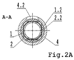
図1に示されるように、液体医薬調剤、特に、インスリン、より詳細には、交換可能な容器からの設定投与量の薬剤の複数回注入投与用の自動アプリケータのための表示機構部は、互いに可動的に連結された少なくとも2個の外筒の組立体を備え、駆動外筒1に取り付けられた表示外筒2は、この表示外筒の外面にマーキング2.1(図2)だけを備え、プルプッシュ式制御ナット3に同軸的に接続されている。機構部全体は、ハウジング4内に置かれている。図1、図2、図2A、図2B、図2C、図3および図4に表されているように、表示外筒2は、ここでは、駆動外筒1の溝1.2と表示外筒2のキー2.2とを備えるキー溝付きカップリングを用いて、駆動外筒1に摺動的、同軸的、かつ、長さ方向に取り付けられ、キー2.2は、のバヨネット式のキーである。
As shown in FIG. 1, a display mechanism for an automatic applicator for multiple infusion administration of a liquid pharmaceutical formulation, in particular insulin, more particularly a set dose of drug from a replaceable container comprises: The display
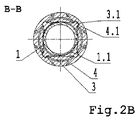
表示外筒2は、この表示外筒2の動作範囲を画定する表示外筒の2つの端位置の間を摺動するように取り付けられている。駆動外筒1は、回転自在に取り付けられている。プルプッシュ式制御ナット3は、ここでは、駆動外筒1のネジ溝1.1と、制御ナットのネジ山(ネジリブ)3.2とを備える、戻り止めのための仕掛けを有しないネジを有するネジカップリングによって、駆動外筒1に回転自在に取り付けられている。プルプッシュ式制御ナット3は、キー溝付きカップリングを用いて、アプリケータ・ハウジング4内に摺動的、同軸的、かつ、長さ方向に取り付けられている。キー溝付きカップリングは、ハウジング4の溝4.1と制御ナット3のキー3.1とを備えるのが好ましい。The display
表示外筒2は、留め具ユニットによってプルプッシュ式制御ナット3の長さ方向に取り付けられている。留め具ユニットは、表示外筒2の表示外筒留め具2.3と制御ナット3の制御ナット留め具3.3とを備える円周方向留め具ユニットであるとよい。表示外筒2は、表示外筒2の外面がアプリケータ・ハウジング4の内面から定められた距離に配置されている状態で駆動外筒1に取り付けられ、ハウジング4は、点検窓4.2を備える。表示外筒2の外面上の表示マーキング2.1は、ここでは、螺旋状に配置された表示数字の形をしている。駆動外筒1は、弾性手段、ここでは、螺旋状スプリング5(図5)である駆動要素に接続されている。
The display
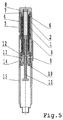
図5に示されるように、駆動外筒1は、回転ノブ8と、クラッチ6と、ここでは、螺旋状スプリング5である弾性要素と、スプリング要素ブロック7と、プランジャ11と、ラチェット機構部12と、ナット13と、プランジャ遮断スリーブ14と、プランジャブロック10と、トリガ9と、容器ハウジング15と、を備える組立体の形をした薬剤投与量設定のための機構部に接続されている。
As shown in FIG. 5, the drive
液体医薬調剤、特に、インスリン、より詳細には、交換可能な容器からの薬剤の設定投与量の複数回注入投与のための自動アプリケータのための表示機構部は、以下の通り動作する。 A display mechanism for an automatic applicator for multiple infusion administration of a liquid pharmaceutical formulation, in particular insulin, more particularly a set dose of drug from a replaceable container, operates as follows.
投与量が設定されるとき、駆動外筒1は、針の方向に向かって時計回り(増分設定)、または、反時計回り(補正設定)に回され、制御ナット3は、制御ナット3の内側ネジリブ3.2が、円筒状駆動外筒1の外壁に切りこまれたネジ溝1.1内を移動するネジカップリングによって、駆動外筒1に沿って移動する。プルプッシュ式制御ナット3は、キー3.1によって、回転しないように固定される。キー3.1はハウジング4の内部円筒壁に作られた対応する溝4.1内で同軸的に移動する。この接続は、溝4.1内をキー3.1が同軸摺動運動するので、制御ナット3の外部円筒とハウジング4の内部円筒壁との間の増加したクリアランスを維持することを可能にさせ、これらの2つの円筒部品の間の摩擦の除去に寄与し、図2Bにおいて矢印によって示された力によって表示機構部を回転の中心点に維持する。
When the dosage is set, the driving
制御ナット3は、ハウジング4に沿って移動する間に、表示外筒2の対応する表示外筒留め具2.3に回転のため接続されている制御ナット3の制御ナット留め具3.3を用いて、表示外筒2を(増加設定中に)後方に引き寄せるか、または、(補正設定中に)逆方向に押す。表示外筒2は、表示外筒が制御ナット3によって同軸方向に引かれるか、または、押されると、これに従って動作する。表示外筒は、表示外筒のキー2.2と円筒状駆動外筒1の外壁上の溝1.2とを用いて駆動外筒に連結されているので、駆動外筒1と一緒に同時に回転する。このような接続は、溝1.2内をキー2.2が同軸摺動運動するので、駆動外筒1の外部円筒と表示外筒2の内部円筒壁との間で増加したクリアランスを維持することを可能にし、これら2個の円筒部品の間の摩擦の除去に寄与する。そして、図2Aおよび図2Bで矢印によって示された力を用いて表示機構部を回転の中心点に維持する。前記の制御ナット3に従った表示外筒2の動作は、ハウジング4内の点検窓4.2に対する螺旋状運動であり、この運動は、駆動外筒1に対する表示外筒2の変位の範囲内で、ハウジング4に対する表示外筒2のあらゆる数の完全な回転を可能にさせる。
While the
回転の方向は変更できるので、増加設定は、反時計回りの方向に駆動外筒1を回すことによって達成されることを強調しておく。このような構成では、減少設定は、時計回りの方向に駆動外筒1を回すことによって達成することができる。
Since the direction of rotation can be changed, it is emphasized that the increase setting is achieved by turning the drive
自動アプリケータのための本表示機構部の構造は、キー溝付きカップリングによって接合された協働円筒の原理に基づいており、要素の円筒面間に摩擦が存在しない。このため、他の駆動要素および/または弾性要素からの力は、より小さくなる可能性があり、投与量設定および投与のプロセスの間にアプリケータのより一様な動作をもたらす。キー溝付きカップリングによって確保された、協働する要素の理想的な軸方向位置合わせは、薬剤投与の精度に好ましい効果を与え、投与量設定中の逆流の発生、実際に投与される投与量の減少を除去し、投与される投与量がまさに設定された通りになることを可能にする。 The structure of the present display mechanism for an automatic applicator is based on the principle of a cooperating cylinder joined by a keyed coupling and there is no friction between the cylindrical surfaces of the elements. For this reason, forces from other drive and / or elastic elements may be smaller, resulting in a more uniform movement of the applicator during the dose setting and dosing process. The ideal axial alignment of the cooperating elements secured by the keyed coupling has a positive effect on the accuracy of drug administration, the occurrence of backflow during dose setting, the actual dose administered This allows the dose administered to be exactly as set.
本発明の本質は、自動アプリケータの表示要素の3重カップリングであり、すなわち、表示外筒2と、駆動外筒1および制御ナット3とが多重的に協働して、不正確な投与量設定を減少させる正確な制御を可能とし、ストレスなしに薬剤の自動投与を持続し、特に、インスリン、より詳細には、交換可能な容器からの設定投与量の薬剤の複数回注入投与のための自動アプリケータの長期使用を確実にする。
The essence of the present invention is the triple coupling of the display element of the automatic applicator, i.e. the display
Claims (14)
前記表示機構部は、アプリケータハウジング(4)と、互いに可動的に連結された少なくとも2個の外筒の組立体を備え、前記組立体は前記アプリケータハウジング(4)の内 部の駆動外筒(1)と前記駆動外筒(1)に取り付けられた表示外筒(2)とを含み、
前記表示外筒(2)が前記表示外筒の外面に表示マーキング(2.1)を備え、
前記表示外筒(2)は、キーカップリングによって、摺動的、同軸的、かつ、長さ方向に、前記駆動外筒(1)の外部表面に直接取り付けられ、前記表示外筒(2)は前記アプリケータハウジング(4)の内面に接することなく、
前記表示外筒(2)の隣に配置された別体のプルプッシュ式制御ナット(3)に同軸的かつ直接に前記表示外筒(2)の先端部が接続され、前記プルプッシュ式制御ナット(3)は、ねじカップリングによって前記駆動外筒(1)に回転可能に取り付けられ、前記表示外筒(2)は前記プルプッシュ式制御ナット(3)によって前記駆動外筒(1)に沿って同軸的及び長さ方向に引かれ、または押される、表示機構部。A display mechanism for an automatic applicator for multiple infusion administration of a set dose of drug from an exchangeable container,
The display mechanism includes, an applicator housing (4), comprising an assembly of at least two of the outer cylinder are movably connected to each other, the assembly is driven out of the inner portion of the applicator housing (4) A cylinder (1) and a display outer cylinder (2) attached to the drive outer cylinder (1);
The display outer cylinder (2) is provided with indication markings (2.1) on the outer surface of the display outer cylinder,
The display outer cylinder (2) is keyed coupling, slidingly, coaxially and in the longitudinal direction, is mounted directly on the outer surface of the drive outer cylinder (1), wherein the display outer cylinder (2) without contacting the inner surface of the applicator housing (4),
The tip portion of the display outer cylinder coaxially and directly (2) is connected to the pull push control nut display barrel separately disposed next to (2) (3), the pull push control nut (3) is rotatably attached to the driving outer cylinder (1) by screw coupling, and the display outer cylinder (2) is aligned with the driving outer cylinder (1) by the pull-push type control nut (3). pulled coaxially and longitudinally Te, or is pressed, the display mechanism.
Applications Claiming Priority (3)
| Application Number | Priority Date | Filing Date | Title |
|---|---|---|---|
| PL388694A PL214940B1 (en) | 2009-07-31 | 2009-07-31 | Indication mechanism of an automatic applicator, especially for insulin |
| PLP388694 | 2009-07-31 | ||
| PCT/EP2010/054125 WO2010089417A2 (en) | 2009-07-31 | 2010-03-29 | An indication mechanism for an automatic applicator, particularly for insulin |
Publications (2)
| Publication Number | Publication Date |
|---|---|
| JP2013500097A JP2013500097A (en) | 2013-01-07 |
| JP5483776B2 true JP5483776B2 (en) | 2014-05-07 |
Family
ID=42542445
Family Applications (1)
| Application Number | Title | Priority Date | Filing Date |
|---|---|---|---|
| JP2012522043A Active JP5483776B2 (en) | 2009-07-31 | 2010-03-29 | Display mechanism part of an automatic applicator for insulin in particular |
Country Status (15)
| Country | Link |
|---|---|
| US (5) | US8894619B2 (en) |
| EP (1) | EP2459253B1 (en) |
| JP (1) | JP5483776B2 (en) |
| KR (5) | KR20170117221A (en) |
| CN (2) | CN102470214B (en) |
| AU (1) | AU2010210089B2 (en) |
| BR (1) | BR112012001421B8 (en) |
| CA (1) | CA2767735C (en) |
| DE (4) | DE202010018495U1 (en) |
| ES (1) | ES2720285T3 (en) |
| HK (1) | HK1168308A1 (en) |
| PL (2) | PL214940B1 (en) |
| RU (1) | RU2520159C2 (en) |
| TR (1) | TR201905498T4 (en) |
| WO (1) | WO2010089417A2 (en) |
Families Citing this family (25)
| Publication number | Priority date | Publication date | Assignee | Title |
|---|---|---|---|---|
| US7959598B2 (en) | 2008-08-20 | 2011-06-14 | Asante Solutions, Inc. | Infusion pump systems and methods |
| PL214940B1 (en) * | 2009-07-31 | 2013-09-30 | Lozano Platonoff Alberto | Indication mechanism of an automatic applicator, especially for insulin |
| PL215310B1 (en) | 2009-10-30 | 2013-11-29 | Kappa Medilab Spolka Z Ograniczona Odpowiedzialnoscia | Automatic applicator, especially for insulin |
| CN103747824B (en) * | 2011-08-24 | 2016-08-17 | 尤尼特拉克特注射器控股有限公司 | Automatic injector for concertina type precharging type syringe |
| WO2013063516A1 (en) | 2011-10-28 | 2013-05-02 | Neotope Biosciences Limited | Humanized antibodies that recognize alpha-synuclein |
| CN103974732B (en) * | 2011-12-14 | 2016-08-24 | 诺沃—诺迪斯克有限公司 | There is the injection pen of the mechanical dose display part including big digital code |
| PL220720B1 (en) | 2012-02-08 | 2015-12-31 | Copernicus Spółka Z Ograniczoną Odpowiedzialnością | Injection device with a reset mechanism of the dose |
| EP2692376B1 (en) * | 2012-08-01 | 2019-04-03 | TecPharma Licensing AG | Injection device with helical or spiral dose scale |
| EP2914340B1 (en) * | 2012-11-05 | 2020-10-14 | Nucletron Operations B.V. | Methods of making a medical applicator |
| DE102013007389A1 (en) * | 2013-04-30 | 2014-10-30 | Britannia Pharmaceuticals Ltd. | Drug delivery device |
| US9561324B2 (en) | 2013-07-19 | 2017-02-07 | Bigfoot Biomedical, Inc. | Infusion pump system and method |
| KR102461754B1 (en) | 2013-08-29 | 2022-11-02 | 사노피-아벤티스 도이칠란트 게엠베하 | Housing and cap for an injection device made of an outer metal part and an inner plastic part |
| US10549046B2 (en) * | 2013-09-03 | 2020-02-04 | Sanofi | Drive mechanism for a drug delivery device |
| WO2015032782A1 (en) | 2013-09-03 | 2015-03-12 | Sanofi | Pen type drug injection device with dose limiting nut to prevent setting of a dose higher than the amount of drug remaining |
| CN105764546B (en) * | 2013-11-22 | 2020-07-17 | 赛诺菲-安万特德国有限公司 | Spring assisted drug delivery device |
| US10569015B2 (en) | 2013-12-02 | 2020-02-25 | Bigfoot Biomedical, Inc. | Infusion pump system and method |
| EP2881131B1 (en) * | 2013-12-05 | 2019-04-24 | TecPharma Licensing AG | Drive and metering device for an injection device with a pre-tensioned drive spring |
| KR101976299B1 (en) * | 2014-12-12 | 2019-05-07 | 에스에이치엘 메디컬 아게 | Dose setting mechanism and medicament delivery device comprising the dose setting mechanism |
| US9878097B2 (en) | 2015-04-29 | 2018-01-30 | Bigfoot Biomedical, Inc. | Operating an infusion pump system |
| PL414382A1 (en) | 2015-10-15 | 2017-04-24 | Copernicus Spółka Z Ograniczoną Odpowiedzialnością | Setting mechanism, in particular for dosing |
| CN114053517A (en) | 2016-01-05 | 2022-02-18 | 比格福特生物医药公司 | Operating a multi-mode drug delivery system |
| US10449294B1 (en) | 2016-01-05 | 2019-10-22 | Bigfoot Biomedical, Inc. | Operating an infusion pump system |
| PL232651B1 (en) * | 2017-07-18 | 2019-07-31 | Copernicus Spolka Z Ograniczona Odpowiedzialnoscia | Coupling with locking system for the medical injecting device |
| CN112472996B (en) * | 2020-11-18 | 2022-11-25 | 慕尚未来美容用品(广东)有限公司 | Cosmetic gyro wheel |
| CN113559352B (en) * | 2021-09-27 | 2022-01-18 | 时新(上海)产品设计有限公司 | Micro-dose output structure, micro-dose secretion pump and insulin pump |
Family Cites Families (19)
| Publication number | Priority date | Publication date | Assignee | Title |
|---|---|---|---|---|
| DK166948B1 (en) * | 1988-02-10 | 1993-08-09 | Dcp Af 1988 As | DOSING UNIT FOR DOSING A NUMBER OF MEASURED QUANTITIES OF A FLUID, SUCH AS INSULIN, FROM A GLASS STUBLE |
| GB8809115D0 (en) | 1988-04-18 | 1988-05-18 | Turner R C | Syringes |
| AU5930990A (en) * | 1989-07-08 | 1991-02-06 | Gesine Hirsch | Syringe for injecting metered quantities of various liquid therapeutic agents |
| DK175491D0 (en) * | 1991-10-18 | 1991-10-18 | Novo Nordisk As | APPARATUS |
| DE69900026T2 (en) | 1998-01-30 | 2001-05-10 | Novo Nordisk As | AN INJECTION SYRINGE |
| SE9901366D0 (en) * | 1999-04-16 | 1999-04-16 | Pharmacia & Upjohn Ab | Injector device and method for its operation |
| US6899699B2 (en) | 2001-01-05 | 2005-05-31 | Novo Nordisk A/S | Automatic injection device with reset feature |
| DE10229138B4 (en) * | 2002-06-28 | 2008-01-31 | Tecpharma Licensing Ag | Product diverter with piston rod emergency reset |
| AU2005291585B2 (en) * | 2004-10-04 | 2011-04-07 | Sanofi-Aventis Deutschland Gmbh | Drive mechanism for a drug delivery device |
| EP1645301A1 (en) * | 2004-10-11 | 2006-04-12 | Novo Nordisk A/S | Injection device |
| WO2006045528A1 (en) | 2004-10-21 | 2006-05-04 | Novo Nordisk A/S | Injection device with torsion spring and rotatable display |
| US8221356B2 (en) * | 2004-10-21 | 2012-07-17 | Novo Nordisk A/S | Medication delivery system with a detector for providing a signal indicative of an amount of a set and/or ejected dose of drug |
| JP5178202B2 (en) * | 2004-12-01 | 2013-04-10 | ノボ・ノルデイスク・エー/エス | Injection device |
| CA2594764C (en) * | 2005-01-21 | 2014-01-14 | Novo Nordisk A/S | An automatic injection device with a top release mechanism |
| ATE418351T1 (en) | 2005-02-11 | 2009-01-15 | Novo Nordisk As | INJECTION DEVICE |
| PL208660B1 (en) | 2005-05-25 | 2011-05-31 | Kappa Medilab Społka Z Ograniczoną Odpowiedzialnością | Automatic applicator, particularly for application of the insulin |
| DE102007026560A1 (en) * | 2007-06-08 | 2009-01-15 | Tecpharma Licensing Ag | Delivery device with axially movable indicator |
| PL214940B1 (en) * | 2009-07-31 | 2013-09-30 | Lozano Platonoff Alberto | Indication mechanism of an automatic applicator, especially for insulin |
| TW201603852A (en) * | 2014-07-01 | 2016-02-01 | 賽諾菲公司 | Spring arrangement and drug delivery device herewith |
-
2009
- 2009-07-31 PL PL388694A patent/PL214940B1/en unknown
-
2010
- 2010-03-29 CN CN201080033621.XA patent/CN102470214B/en active Active
- 2010-03-29 JP JP2012522043A patent/JP5483776B2/en active Active
- 2010-03-29 CN CN201510320608.7A patent/CN105169530B/en active Active
- 2010-03-29 BR BR112012001421A patent/BR112012001421B8/en active IP Right Grant
- 2010-03-29 KR KR1020177027869A patent/KR20170117221A/en not_active Application Discontinuation
- 2010-03-29 KR KR1020177027029A patent/KR101847881B1/en active IP Right Grant
- 2010-03-29 DE DE202010018495.9U patent/DE202010018495U1/en not_active Expired - Lifetime
- 2010-03-29 KR KR1020177027873A patent/KR20170116237A/en not_active Application Discontinuation
- 2010-03-29 WO PCT/EP2010/054125 patent/WO2010089417A2/en active Application Filing
- 2010-03-29 TR TR2019/05498T patent/TR201905498T4/en unknown
- 2010-03-29 KR KR1020127005120A patent/KR101717663B1/en active IP Right Grant
- 2010-03-29 DE DE202010018496.7U patent/DE202010018496U1/en not_active Expired - Lifetime
- 2010-03-29 EP EP10712733.4A patent/EP2459253B1/en active Active
- 2010-03-29 KR KR1020177006740A patent/KR101783430B1/en active IP Right Grant
- 2010-03-29 CA CA2767735A patent/CA2767735C/en active Active
- 2010-03-29 ES ES10712733T patent/ES2720285T3/en active Active
- 2010-03-29 DE DE202010018494.0U patent/DE202010018494U1/en not_active Expired - Lifetime
- 2010-03-29 AU AU2010210089A patent/AU2010210089B2/en active Active
- 2010-03-29 PL PL10712733T patent/PL2459253T3/en unknown
- 2010-03-29 RU RU2012107490/14A patent/RU2520159C2/en active
- 2010-03-29 DE DE202010018493.2U patent/DE202010018493U1/en not_active Expired - Lifetime
-
2012
- 2012-01-31 US US13/362,578 patent/US8894619B2/en not_active Expired - Fee Related
- 2012-09-12 HK HK12108923.1A patent/HK1168308A1/en unknown
-
2014
- 2014-10-24 US US14/523,012 patent/US9248237B2/en active Active
-
2015
- 2015-12-17 US US14/972,493 patent/US9402958B2/en active Active
- 2015-12-17 US US14/972,484 patent/US9795742B2/en active Active
-
2017
- 2017-09-25 US US15/713,741 patent/US20180008777A1/en not_active Abandoned
Also Published As
Similar Documents
| Publication | Publication Date | Title |
|---|---|---|
| JP5483776B2 (en) | Display mechanism part of an automatic applicator for insulin in particular | |
| KR101988582B1 (en) | Automatic applicatior for liquid pharmaceutical preparations, particularly for insulin | |
| US7678084B2 (en) | Medication dispensing apparatus with gear set for mechanical advantage | |
| PL214935B1 (en) | Indication mechanism of an automatic applicator, especially for insulin | |
| CN113301931B (en) | Injection device | |
| US20220088313A1 (en) | Injection Device | |
| PL214934B1 (en) | Indication mechanism of an automatic applicator, especially for insulin |
Legal Events
| Date | Code | Title | Description |
|---|---|---|---|
| A521 | Request for written amendment filed |
Free format text: JAPANESE INTERMEDIATE CODE: A523 Effective date: 20120125 |
|
| A621 | Written request for application examination |
Free format text: JAPANESE INTERMEDIATE CODE: A621 Effective date: 20120125 |
|
| A131 | Notification of reasons for refusal |
Free format text: JAPANESE INTERMEDIATE CODE: A131 Effective date: 20130416 |
|
| A521 | Request for written amendment filed |
Free format text: JAPANESE INTERMEDIATE CODE: A523 Effective date: 20130712 |
|
| A521 | Request for written amendment filed |
Free format text: JAPANESE INTERMEDIATE CODE: A523 Effective date: 20130712 |
|
| TRDD | Decision of grant or rejection written | ||
| A01 | Written decision to grant a patent or to grant a registration (utility model) |
Free format text: JAPANESE INTERMEDIATE CODE: A01 Effective date: 20140212 |
|
| A61 | First payment of annual fees (during grant procedure) |
Free format text: JAPANESE INTERMEDIATE CODE: A61 Effective date: 20140217 |
|
| R150 | Certificate of patent or registration of utility model |
Ref document number: 5483776 Country of ref document: JP Free format text: JAPANESE INTERMEDIATE CODE: R150 |
|
| R250 | Receipt of annual fees |
Free format text: JAPANESE INTERMEDIATE CODE: R250 |
|
| R250 | Receipt of annual fees |
Free format text: JAPANESE INTERMEDIATE CODE: R250 |
|
| R250 | Receipt of annual fees |
Free format text: JAPANESE INTERMEDIATE CODE: R250 |
|
| R250 | Receipt of annual fees |
Free format text: JAPANESE INTERMEDIATE CODE: R250 |
|
| R250 | Receipt of annual fees |
Free format text: JAPANESE INTERMEDIATE CODE: R250 |
|
| R250 | Receipt of annual fees |
Free format text: JAPANESE INTERMEDIATE CODE: R250 |
|
| R250 | Receipt of annual fees |
Free format text: JAPANESE INTERMEDIATE CODE: R250 |