JP5481703B2 - Mascara tools - Google Patents
Mascara tools Download PDFInfo
- Publication number
- JP5481703B2 JP5481703B2 JP2009196585A JP2009196585A JP5481703B2 JP 5481703 B2 JP5481703 B2 JP 5481703B2 JP 2009196585 A JP2009196585 A JP 2009196585A JP 2009196585 A JP2009196585 A JP 2009196585A JP 5481703 B2 JP5481703 B2 JP 5481703B2
- Authority
- JP
- Japan
- Prior art keywords
- brush
- mascara
- motor
- storage container
- cylindrical
- Prior art date
- Legal status (The legal status is an assumption and is not a legal conclusion. Google has not performed a legal analysis and makes no representation as to the accuracy of the status listed.)
- Expired - Fee Related
Links
- 238000012856 packing Methods 0.000 claims description 12
- 210000000720 eyelash Anatomy 0.000 description 25
- 210000004209 hair Anatomy 0.000 description 11
- 239000003638 chemical reducing agent Substances 0.000 description 5
- 230000007613 environmental effect Effects 0.000 description 5
- 230000000694 effects Effects 0.000 description 3
- 238000005192 partition Methods 0.000 description 3
- 210000000707 wrist Anatomy 0.000 description 3
- 239000000853 adhesive Substances 0.000 description 2
- 230000001070 adhesive effect Effects 0.000 description 2
- 239000000835 fiber Substances 0.000 description 2
- 239000007788 liquid Substances 0.000 description 2
- 230000002093 peripheral effect Effects 0.000 description 2
- 229920005989 resin Polymers 0.000 description 2
- 239000011347 resin Substances 0.000 description 2
- 230000002411 adverse Effects 0.000 description 1
- 229920006167 biodegradable resin Polymers 0.000 description 1
- 238000004140 cleaning Methods 0.000 description 1
- 239000002537 cosmetic Substances 0.000 description 1
- 239000006071 cream Substances 0.000 description 1
- 230000007547 defect Effects 0.000 description 1
- 238000003780 insertion Methods 0.000 description 1
- 230000037431 insertion Effects 0.000 description 1
- 230000010354 integration Effects 0.000 description 1
- 238000012423 maintenance Methods 0.000 description 1
- 239000000463 material Substances 0.000 description 1
- 239000007787 solid Substances 0.000 description 1
- 238000004528 spin coating Methods 0.000 description 1
- 239000000758 substrate Substances 0.000 description 1
- 229920003002 synthetic resin Polymers 0.000 description 1
- 239000000057 synthetic resin Substances 0.000 description 1
- 239000002699 waste material Substances 0.000 description 1
Images


Description
この発明は、ブラシ毛を自動回転させることによって、まつ毛のカール方向に沿ってマスカラ(化粧材)をそのまつ毛上に付着させるマスカラ用具に関するものである。 The present invention relates to a mascara device for attaching a mascara (decorative material) onto the eyelashes along the curl direction of the eyelashes by automatically rotating the brush hairs.
マスカラは化粧品の一種で、まつ毛を濃く、長く又はカールしているように見せるものであり、液状、固形状及びクリーム状の3タイプがあって、カラー(色)は、黒、茶、紺などが主流であり、透明なものもある。
そのマスカラは、通常、有底筒状容器に収納され、その容器に棒状ブラシが差し込まれて、そのブラシ毛にマスカラを付着した状態となっており(図2参照)、例えば、図11(a)、(b)に示すように、容器からブラシ20を引き抜いて手に持ち、そのブラシ毛21をまつ毛aにあてがい、手首を回すことによって、まつ毛aのカールの方向に沿ってブラシ20(ブラシ毛21)を回転させてブラシ毛21に付着するマスカラbをまつ毛aに塗布する。
Mascara is a type of cosmetics that makes your eyelashes appear dark, long, or curled, and is available in three types: liquid, solid, and cream. Is the mainstream and some are transparent.
The mascara is usually stored in a bottomed cylindrical container, and a rod-shaped brush is inserted into the container, and the mascara is attached to the brush hair (see FIG. 2). For example, FIG. ), (B), pulling out the
このとき、初心者や手の動きの良くない者、さらに、手の動きに不便のある者には、手首を回しまつ毛aに沿ってブラシ毛21を回転させる動作は容易ではなく、上手くその操作ができない。
このため、この発明の対象であるブラシ20を自動回転させるマスカラ用具が種々考案されている(特許文献1〜3参照)。
At this time, for beginners, persons with poor hand movement, and persons with inconvenience in hand movement, the operation of rotating the
For this reason, various mascara tools for automatically rotating the
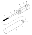
この種のブラシ20を自動回転させるマスカラ用具は、この発明に係る一実施形態を示す図1〜図4を参照して説明すると、有底筒状のマスカラ収納容器10と、その収納容器10に差し込まれる棒状ブラシ20と、そのブラシ20を回転自在に支持する握持部30、40とからなり、その握持部にモータ43、電源(電池)45及び制御基板44を収納したものが一般的である。
このマスカラ用具は、握持部を手で持ち、スイッチ46でもって、モータ43を駆動し、この駆動によってブラシ20を回転させ、この回転状態のブラシ毛21をまつ毛aに当てがい、まつ毛aのカール方向に沿ってマスカラbをそのまつ毛a上に付着させるとともにまつ毛aをカールさせる。又は、ブラシ毛21をまつ毛aにあてた後、モータ43を駆動させてマスカラbのまつ毛aへの付着とカールを行う。
A mascara tool for automatically rotating this type of
This mascara tool has a gripping part by hand, drives a
また、そのマスカラbをまつ毛aに円滑に付着させるために、ブラシ20を振動させるものもある(特許文献1参照)。そのブラシ20の振動は、モータの回転軸に偏心振動子(偏心ブロック)を設け、その回転軸による偏心振動子の回転に伴う振動によって行う(本願図6参照)。このとき、ブラシ20を振動させるだけで、ブラシ20を回転させないものや、ブラシ20を振動させるとともに回転させるものもある。
Moreover, in order to make the mascara b adhere smoothly to the eyelashes a, there is one that vibrates the brush 20 (see Patent Document 1). The vibration of the
上記ブラシ20を自動回転させるマスカラ用具は、そのマスカラ動作を簡便にした点においては有効なものであるが、収納されたマスカラbがなくなれば、全てが廃棄処分とされている。
今日の環境問題の高まりの下、その廃棄されるマスカラ用具には、まだ充分に使用し得るモータ43や電池45が残っており、そのモータ等の廃棄は問題である。
The mascara tool for automatically rotating the
Under the growing environmental problems of today, the discarded mascara tools still have a
また、従来のブラシ20を振動させるマスカラ用具において、ブラシ20を回転させないものは、手首を回転させて用具(ブラシ20)を回転させる必要があり、上記初心者等における問題がある。
ブラシ20を振動及び回転させるマスカラ用具は、その振動を得るための回転数とブラシ20を回転させる回転数は、通常、前者の振動を与える回転数が数千rpm(数千回/分)であるのに対し、ブラシ回転は数十rpm(数十回/分)である。このため、従来のブラシ20の振動によってそのブラシ20自身を回転させるものは、両者の適切な回転数(振動数)を得ることができず、通常、そのブラシ20の回転が円滑でない問題がある。また、減速機でもって偏心振動子の回転数(振動数)とブラシ20の回転数を適切なものとすることも考え得るが、減速機でもって回転数の異なる2つの回転(軸)を出力しようとすると、その減速機が大きくなる問題がある。マスカラ用具はコンパクト化が望まれており、その要望に反する。
Moreover, in the mascara device that vibrates the
For the mascara tool that vibrates and rotates the
この発明は、環境問題の高まりの下、この種のマスカラ用具においても、環境問題に優しい物とすることを第1の課題、ブラシ20の回転数と振動数を適切なものとすることを第2の課題とする。
In the present invention, the first problem is to make this kind of mascara device friendly to environmental problems even under the growing environmental problems. The first problem is to make the rotation speed and frequency of the
上記第1の課題を達成するために、この発明は、マスカラ容器とブラシは、付着マスカラの洗浄が容易ではないことから、それらは廃棄又は回収することとし、それ以外のモータ等のものは、使用者において再利用し得るようにしたのである。
このようにモータ等の耐久性のある物を再利用することは省資源になり、環境に優しいことである。省資源及び再利用は廃棄物を少なくすることであり、お金の節約にも繋がる。特に、マスカラは女性の生活スタイルの一部となっており、その生活において、環境に優しいことは、今日のエコロジーに対する認識が高まるものである。
In order to achieve the first object, the present invention is that the mascara container and the brush are not easy to wash the attached mascara, so they are discarded or collected, and other motors and the like are It can be reused by the user.
Reusing a durable object such as a motor in this way saves resources and is environmentally friendly. Resource saving and reuse means reducing waste and saving money. In particular, mascara has become a part of women's lifestyles, and environmental friendliness in their lives is a growing awareness of today's ecology.
具体的には、この発明は、有底筒状のマスカラ収納容器と、その収納容器に差し込まれる棒状ブラシと、そのブラシの柄を回転自在に支持して前記収納容器の開口部に同軸上に取付けられる筒状支持部と、この筒状支持部に同軸上に取付けられる筒状操作部とからなり、前記操作部はモータ、そのモータ制御用基板、電池及び操作スイッチが設けられており、その操作部を前記筒状支持部に取付けることによって、前記モータの回転軸がブラシの柄と着脱可能に連結されてモータの回転力がブラシに伝達するようになっている構成としたのである。 Specifically, the present invention provides a bottomed cylindrical mascara storage container, a rod-shaped brush inserted into the storage container, and a handle of the brush rotatably supported coaxially with the opening of the storage container. A cylindrical support portion to be attached and a cylindrical operation portion that is coaxially attached to the cylindrical support portion, the operation portion being provided with a motor, a motor control board, a battery, and an operation switch. By attaching the operation part to the cylindrical support part, the rotation shaft of the motor is detachably connected to the handle of the brush, and the rotational force of the motor is transmitted to the brush.
この構成であると、マスカラ収納容器、ブラシ及びその支持部は廃棄されることとなるが、モータ等を収納した操作部は、新たなマスカラ収納容器、ブラシ及びその支持部からなる部品のその支持部に取付けることによって、新たなマスカラ用具が構成される。このとき、廃棄されるブラシ等も回収して再利用すれば、さらに省資源となる(エコとなる)。回収には、エコポイントを与えて、新しいブラシ等の価額の割引ポイントとすることができる。 With this configuration, the mascara storage container, the brush, and the support portion thereof are discarded, but the operation unit that stores the motor or the like is the support of the parts including the new mascara storage container, the brush, and the support portion thereof. A new mascara tool is constructed by attaching to the part. At this time, if the brushes and the like that are discarded are also collected and reused, resources are further saved (eco-friendly). For collection, eco-points can be given as discount points for new brushes.
この構成において、上記モータ、モータ制御用基板及び電池は、筒状部材内に収納され、その筒状部材の一端部を上記操作部に嵌め込むとともに、筒状部材の他端部を上記支持部に嵌め込むことによって、その支持部に操作部を取付けるようになっている構成とすれば、支持部への操作部の取付けが容易となるとともに、筒状部材内にブラシ駆動部及びその操作部が収納されるため、その筒状部材をさらに分解することによって、その中のモータ等の再利用も容易になる。また、その筒状部材の交換によって駆動部等の修理が行え得る利点もある。さらに、筒状部材内にモータ等が収納されていることは、それらの分別もし易く、廃棄や再利用への可能性が高いものとなる。 In this configuration, the motor, the motor control board, and the battery are housed in a cylindrical member, and one end portion of the cylindrical member is fitted into the operation portion, and the other end portion of the cylindrical member is connected to the support portion. If the operation part is attached to the support part by being fitted into the support part, the operation part can be easily attached to the support part, and the brush drive part and the operation part are provided in the cylindrical member. Therefore, by further disassembling the cylindrical member, it becomes easy to reuse the motor and the like therein. Further, there is an advantage that the drive unit and the like can be repaired by replacing the cylindrical member. Furthermore, since the motor or the like is housed in the cylindrical member, it is easy to separate them, and the possibility of disposal or reuse is high.
上記第2の課題を達成するために、この発明は、今日の小型(マイクロ)モータの小型化傾向に鑑み、ブラシの回転と振動をそれぞれ別のモータで行うこととしたのである。
今日、小型モータは、益々、小型化(マイクロ化)が進んでおり、上記の回転数の異なる2つの回転(軸)を出力する減速機に比べれば、2つのモータが必要とするスペースも少なくてすむとともに、両モータは同軸上に容易に設けることができて、振動を回転するブラシ毛に円滑に伝達し得て、その振動によるマスカラの円滑な塗布を得ることができる。ブラシの回転中心と振動中心が偏位していると、振動が回転にその回転中心の振れ等の悪影響を与えて、安定した回転を望めない。
In order to achieve the second problem, the present invention is configured to perform rotation and vibration of the brush by separate motors in view of the trend toward miniaturization of today's small (micro) motors.
Today, small motors are increasingly miniaturized (micro), and less space is required for two motors than the reduction gears that output two rotations (shafts) with different rotation speeds. In addition, both motors can be easily provided on the same axis, and vibrations can be smoothly transmitted to rotating bristles, and a smooth application of mascara due to the vibrations can be obtained. If the center of rotation of the brush and the center of vibration are deviated, the vibration will adversely affect the rotation, such as shake of the center of rotation, and stable rotation cannot be expected.
この第2の課題を達成する発明の具体的な構成としては、上記ブラシ毛の回転用モータに別のモータを固定して設け、その別のモータの回転軸に偏心振動子を設けた構成を採用することができる。
このように、両モータを相互に固定して一体化すれば、一つのモータでもって「回転」と「振動」を行う場合と同様になってブラシの安定した回転と振動を得ることができる。このとき、両モータの軸心(回転軸)は同一軸上とすることが好ましい。
As a specific configuration of the invention for achieving the second problem, a configuration in which another motor is fixed to the brush hair rotation motor and an eccentric vibrator is provided on the rotation shaft of the other motor is provided. Can be adopted.
Thus, if the two motors are fixed and integrated with each other, the stable rotation and vibration of the brush can be obtained in the same manner as when “rotation” and “vibration” are performed with one motor. At this time, it is preferable that the shaft centers (rotating shafts) of both motors are on the same axis.
なお、第1の課題を達成する上記構成と第2の課題を達成する上記構成は、マスカラ用具に併用したり、それぞれ別に設けたりすることができる。例えば、2つのモータでブラシの回転と振動を行う構成は、第1の課題を達成する上記構成を有するマスカラ用具に限らず、従来のブラシ20を自動回転させるマスカラ用具にも採用し得る。
In addition, the said structure which achieves the 1st subject and the said structure which achieves the 2nd subject can be used together in a mascara tool, or can be provided separately, respectively. For example, the configuration in which the brush rotates and vibrates with two motors is not limited to the mascara device having the above-described configuration that achieves the first problem, but can also be employed in a mascara device that automatically rotates the
この発明は、以上のように、有底筒状のマスカラ収納容器と、棒状ブラシと、そのブラシの支持部と、操作部とからなる構成として、操作部を再利用可能としたので、環境に優しい物となる。
また、2つのモータによりブラシ毛の回転と振動を行えば、大型化を招くことなく、その個別のモータの回転数を制御することによって、ブラシ毛の最適な回転数と最適な振動数を容易に得ることができる。
As described above, the present invention has a configuration including the bottomed cylindrical mascara storage container, the rod-shaped brush, the support portion of the brush, and the operation unit, so that the operation unit can be reused. It becomes a gentle thing.
In addition, if the bristles rotate and vibrate with two motors, the optimum number of bristles and the optimum frequency can be easily controlled by controlling the number of revolutions of the individual motors without increasing the size. Can get to.
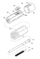
一実施形態を図1〜図5に示し、この実施形態は、有底筒状のマスカラ収納容器10と、その収納容器10に差し込まれる棒状ブラシ20と、そのブラシ20の柄21を回転自在に支持して前記収納容器10の開口部11に同軸上に取付けられる筒状支持部30と、この筒状支持部30に同軸上に取付けられる筒状操作部40とからなる。これら10、20、30、40は、それぞれ合成樹脂からなる一体成型品であって、環境保護の面から、その樹脂は生分解性樹脂を採用することが好ましい。
An embodiment is shown in FIGS. 1 to 5. In this embodiment, a bottomed cylindrical
上記収納容器10には、ファイバー混入の液状マスカラbを収納し、そのマスカラbの性状は、自動回転塗布を考慮して、前記ファイバーの大きさ及び量や粘度を適宜に設定する。
ブラシ20は、その先端部の針金を螺旋状に捩った線条体に稙毛したブラシ毛21と、そのブラシ毛21の端を圧入固定した柄22とからなる。その稙毛(ブラシ毛)21の量、長さ、密度も自動回転塗布を考慮して、適宜に設定する。また、図1鎖線のように、ブラシ毛21の周表面は凹円弧状(鼓状)にカーブを付ければ、まつ毛の生えている形状にその周表面が沿うため、マスカラbをまつ毛aに均一に塗布することができる。
The
The
容器10の開口部11には筒状のゴム製パッキング12がその両端面の環状突起12aを開口部11の端面又は段部に係止して嵌められている。このパッキング20は、容器10からのマスカラbの漏れ出しを抑制するとともに、ブラシ20を容器10から抜き出す際、そのブラシ毛21が触れることによって、ブラシ毛21内のマスカラbを適宜に削ぎ落して滴量にする。
なお、ブラシ20を容器10内に納めた際、パッキング12をブラシ柄22に接しさせてマスカラbの漏れ出しを確実に防止するようにすることもできる。
A cylindrical rubber packing 12 is fitted into the
In addition, when the
支持部30は、中程に隔壁31を有し、その隔壁31中央の支持孔32に、上記ブラシ20をそのブラシ毛21側から差し入れて(図2(b)の右側から左方向に差し入れて)、ブラシ20をこの支持部30に取付ける。そのとき、柄22の端の突起23が支持孔32周囲の隔壁段部31aに当たってその以上の差し込みが阻止される。すなわち、ブラシ20は支持部30から容器10側には抜けない。
そのブラシ20の取付けは、柄22を支持孔32に差し込んだ後に、ブラシ毛21を柄22に取付けても良いが、ブラシ毛21付きの柄22を支持孔32に差し込んでも良い。後者の場合、ブラシ毛21が撓んで支持孔32を通過することとなる。前記突起23の端面は、十字状の溝24が形成されている(図4参照)。
The
The
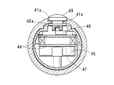
操作部40は、有蓋円筒状のキャップ41と、そのキャップ41に一端部が嵌る樹脂製筒状部材42とからなる。筒状部材42は、図5に示すように、半割円筒状であり、その前部にモータ43、その後部に2枚の制御基板44が嵌め込みによって設けられる。一方の制御基板44に電池45が、他方の制御基板44にスイッチ46が設けられる。対の半割円筒部は、図示のように連結されていても、連結せずに分かれていても良いが、両者は突起42aとその嵌合孔42b等の構成によって嵌め合わせて一体とされる。
電池45は、止め金具47を制御基板44に嵌めることによって取付けられる。このため、その止め金具47の取り外し・取付けによって電池45の交換が可能である。
The
The
モータ43は減速機43aを介してその端面中央から突出した回転軸に十字状突起48が設けられており、図2(b)、図4に示すように、筒状部材42に内にモータ43が嵌められて固定されると、その筒状部材42の他方端面中央にその十字状突起48は位置する。
このため、筒状部材42の他端部を支持部30に嵌め込むと、図2(b)に示すように、その突起48が上記ブラシ柄22の十字状溝24に嵌って、モータ43の回転力がその十字状突起48、溝24を介してブラシ20に伝達される。
The
Therefore, when the other end portion of the
スイッチ46は、図4に示すように、作動子46aが実線の状態で、制御回路やモータ43等への全ての電源が遮断され、一点鎖線の状態に移動されることによって、前記電源が入り、例えば、モータ43が正回転(右回転)を行い、二点鎖線の状態に移動されることによって、モータ43が逆転(左回転)を行う。その作動子46aは図2に示すように摘み49に嵌る。その摘み49は、図3に示すようにキャップ41の摺動ガイド41aに嵌ってそのガイド長さ方向に移動自在であり、その移動によって、前記作動子46aが上記「停止」、「正回転」、「逆転」の位置に移動する。その摘み49の移動位置に対応して、キャップ41の表面にはその旨を示す表示がなされる。なお、各図中、42dは基板支持杆である。
As shown in FIG. 4, the
この実施形態は以上のような構成であり、図5の状態から、筒状部材42に、モータ43、制御基板44、電池45等を組み込み、図4から図1、図2に示すように、その筒状部材42の一端部をキャップ41に嵌め込んで操作部40を構成するとともに、筒状部材42の他端部をブラシ20を取付けた支持部30に嵌め込むことによって、その支持部30に操作部40を取付ける。
このブラシ20付きの操作部40(支持部30)を容器10にその開口部11からブラシ20を差し込み、その開口部11にねじ込むことによって、不使用状態(販売状態)のマスカラ用具を得る(図2の状態)。
This embodiment is configured as described above. From the state of FIG. 5, the
The operation part 40 (support part 30) with the
使用時(マスカラ時)には、まず、図1に示すように、握持部(支持部30及び操作部40)を手で持ち、容器10からブラシ20を抜き出した後、スイッチ46でもって、モータ43を駆動し、この駆動によってブラシ20を回転させる。
つぎに、図11に示すように、従来と同様に、この回転状態のブラシ20をまつ毛aに当てがい、まつ毛aのカール方向に沿ってマスカラbをそのまつ毛a上に付着させるとともにまつ毛aをカールさせる。又は、ブラシ20をまつ毛aにあてた後、モータ43を駆動させてマスカラbのまつ毛aへの付着とカールを行う。
このとき、握った手に応じて、例えば、右手で持った場合は、上側まつ毛aであれば、ブラシ20をその先に向かって右(時計回り)回転させ、下側まつ毛aであれば、ブラシ20を同左回転させる。
At the time of use (in mascara), first, as shown in FIG. 1, after holding the gripping part (supporting
Next, as shown in FIG. 11, the
At this time, depending on the gripped hand, for example, when holding with the right hand, if it is the upper eyelash a, the
このマスカラ時、ブラシ20が回転することによって、まつ毛aを1本1本均一に包み込んで塗布するため、その仕上がりも美しいものとなる。このため、初心者や手の不自由な者でも美しいマスカラを行うことができる。ブラシ20の回転は、マスカラbの粘性等の性状に基づき適宜に設定すればよいが、例えば、28〜35回/分(rpm)とする。
また、モータ43の駆動によってブラシ20はある程度の振動をするため、その振動が回転に加わることによって、マスカラbの塗布も充分なボリューム、ロング(長時間維持)効果を得ることができるとともに、それらの効果を円滑に得ることができる。
At the time of this mascara, since the
Further, since the
そのブラシ20の振動を確実に得るためには、例えば、図6に示す構造とする。この構造は、上記モータ43にさらに別のモータ51を同一軸上で固定して設け、そのモータ51の回転軸に偏心振動子52を設けたものである。このとき、両モータ43、51及び減速機43aはできるだけ、小型のものを採用する。例えば、図5の筒状部材42内に納まるようにする。
この構成であると、モータ43への通電とともに、モータ51にも通電されて偏心振動子52が回って振動を両モータ43、51に与えてブラシ20が振動する。このため、ブラシ20は回転とともに確実に振動して、マスカラbを塗布することとなる。このとき、ブラシ20の回転とは別に、ブラシ20の振動の有無を選択し得るようにしても良い。例えば、振動用モータ51の駆動(通電・非通電)用スイッチを別に設けることができる。モータ51の回転は、マスカラbの粘性等の性状に基づき適宜に設定すればよいが、例えば、7000〜8000回/分(rpm)とする。
In order to reliably obtain the vibration of the
With this configuration, the
上記の実施形態は、スイッチ46をスライド式としたが、押しボタン式としたり、ロータリ(回転)式としたりし得る。例えば、図7に示すように、摘み49に代えて、筒状部材42の突条56に嵌ってその長さ方向に移動自在の摺動子55を設け、この摺動子55をスイッチ46の作動子46aに嵌めたロータリ式とし得る(図8参照)。
キャップ41は、例えば、同図に示す円筒状として筒状部材42にその軸心周りに回転可能に嵌め、そのキャップ41の突起57を摺動子55の傾斜溝58に嵌める(図8参照)。このため、キャップ41をその軸心周りに左右回転すれば、上記のように、スイッチ46の作動子46aが図9(a)、図9(b)及び図9(c)に示す各状態となって、例えば、モータ43を左回転、停止及び右回転させる。突起57は、棒状として、キャップ41の筒状部材42への嵌め込み時にはそのキャップ41の内面から没した(図7に示す表面から突出した)状態とし、嵌め込み後に押し込むことによって傾斜溝58に嵌めるようにし得る(図8の状態)。突起57は、傾斜溝58に嵌め込んだ後、接着剤等によってキャップ41に固定する。
In the above embodiment, the
The
キャップ41を蓋のない円筒状とすると、その回転が円滑となるが、筒状部材42の一端が開放状態となるため、筒状部材42の一端にはそのキャップ41の一端開口を塞ぐ円板状塞板59を設ける(図7、図8参照)。キャップ41は蓋を有しても回し得るため、塞板59はキャップ41に設けて、有蓋円筒状のキャップ41とすることもできる(図2参照)。
When the
上記の何れの実施形態においても、電池45は乾電池でも良いが、充電池としたり、操作部40内に100V充電機能を付加したりすることができる。
In any of the above embodiments, the
図8に、上記モータ51によるブラシ20の振動機構及びキャップ41の回転によるスイッチ切替え機構を採用した実施形態を示す。
この実施形態に示すように、ブラシ柄22に碗状突起26を設けて、ブラシ20を容器10に挿入した際、その碗状突起26がパッキング12に圧接するようにすれば、仮に、パッキング12内にマスカラbが入ってブラシ柄22を伝って漏れようとしても、その圧接によってその漏れが確実に防止される。突起26は碗状でなくとも、例えば、単に膨出させた形状等でもその洩れを防止し得る態様であれば、何れでも良い。突起26(膨出部)とパッキング12の接触は、圧接でなくとも、接触してマスカラbの洩れを有効に防止する程度の接触圧があればよい(接触状態でよい)。
FIG. 8 shows an embodiment in which a vibration mechanism of the
As shown in this embodiment, when the
なお、図10に示すように、ベアリング27を介在してそのマスカラbの漏れとブラシ20(ブラシ柄22)の円滑な回転を得るようにすることもできる。このとき、筒状支持部30を収納容器開口部11に取付けた際、そのベアリング27にパッキング12が圧接するようにして、収納容器10内のマスカラbが洩れないようにする。
また、同図に示すように、支持部30の容器10へのねじ込み部を筒状部材35でもって構成することもできる。この筒状部材35は、内面に容器開口部11のネジ部にネジ合う雌ねじが形成され、外面が支持部30の筒状部内面とネジ合う雄ねじとしたり、スプライン形状としたりされて支持部30に固定される。その固定には必要に応じて接着剤を使用する。また、筒状部材35の蓋側面には筒状突起36がその周囲に複数設けられており、その突起36に操作部40の筒状部材42の突起42eが嵌って両者35、42が一体となるようになっている。この一体化によって、両筒状部材35、42の位置決め、すなわち、操作部40と支持部30の位置決めがなされる。
さらに、同図に示すように、操作部40側に回転ブッシュ28を設けて、そのブッシュ28にブラシ柄22を差し込み固定するようにし得る。この場合、ブッシュ28へは上記の溝24と突起48等によってモータ回転力を伝達する。このとき、図8のベアリング27を有しない構成では、筒状支持部30を収納容器開口部11に取付けた際、上記碗状突起26がそのブッシュ28の先端部を被うようにする。
As shown in FIG. 10, it is also possible to obtain leakage of the mascara b and smooth rotation of the brush 20 (brush handle 22) through the
Moreover, as shown in the figure, the threaded portion of the
Further, as shown in the figure, a
以上のように、マスカラbの容器10又は支持部30からの漏れ出しを防止するようにすれば、マスカラbが操作部40に入り込む恐れがなくなり、従来のマスカラの回転部への侵入によってその回転不良等に繋がること等もなくなる。また、マスカラbの付着によって再使用ができない部材は、容器10、ブラシ20となり、省資源化により有利となる。このとき、必要があれば、ブッシュ28や筒状部材35(ベアリング27も含む)も取替えればよいが、これら28、35は、マスカラbの付着も少なく、洗浄によって使用が可能になる可能性が高い。
As described above, if leakage of the mascara b from the
因みに、上記の別モータによる振動、碗状突起26、ベアリング27、筒状部材35及び突起36等の構成は、上記各実施形態に限らず、従来の種々のブラシ20を自動回転させるマスカラ用具や自動回転させないマスカラ用具にも適宜に採用し得る。
Incidentally, the configuration of the vibrations by the separate motor, the hook-
10 マスカラ容器
11 マスカラ容器の開口部
12 マスカラ容器の開口部パッキング
20 ブラシ
21 ブラシ毛
22 ブラシの柄
23 ブラシ柄の端の突起
24 十字状溝
26 碗状突起
27 ベアリング
30 ブラシの支持部
31 隔壁
40 操作部
41 キャップ
42 筒状部材
43 モータ
44 制御基板
45 電池
46 スイッチ
48 十字状突起
49 スイッチ摘み
51 振動用モータ
52 偏心振動子
55 スイッチ用摺動子
57 傾斜溝への嵌合突起
58 摺動子の傾斜溝
a まつ毛
b マスカラ
DESCRIPTION OF
Claims (3)
上記操作部(40)は、モータ(43)、そのモータ制御用基板(44)、電池(45)及び操作スイッチ(46)が設けられており、その操作部(40)を上記筒状支持部(30)に取付けることによって、前記モータ(43)の回転軸が上記ブラシの柄(22)と着脱可能に連結されてモータ(43)の回転力がブラシ(20)に伝達するようになっており、
上記モータ(43)に別のモータ(51)を固定して設け、その別のモータ(51)の回転軸に偏心振動子(52)を設けたことを特徴とするマスカラ用具。 A bottomed cylindrical mascara storage container (10), a rod-shaped brush (20) inserted into the storage container (10), and a handle (22) of the brush (20) are rotatably supported to support the storage container (10). A cylindrical support portion (30) coaxially attached to the opening (11) of 10) and a cylindrical operation portion (40) coaxially attached to the cylindrical support portion (30),
The operation unit (40) includes a motor (43), a motor control board (44), a battery (45), and an operation switch (46). The operation unit (40) is connected to the cylindrical support unit. By attaching to (30), the rotating shaft of the motor (43) is detachably connected to the handle (22) of the brush, and the rotational force of the motor (43) is transmitted to the brush (20). you is,
A mascara device, wherein another motor (51) is fixed to the motor (43), and an eccentric vibrator (52) is provided on a rotation shaft of the other motor (51).
Priority Applications (1)
| Application Number | Priority Date | Filing Date | Title |
|---|---|---|---|
| JP2009196585A JP5481703B2 (en) | 2009-08-27 | 2009-08-27 | Mascara tools |
Applications Claiming Priority (1)
| Application Number | Priority Date | Filing Date | Title |
|---|---|---|---|
| JP2009196585A JP5481703B2 (en) | 2009-08-27 | 2009-08-27 | Mascara tools |
Related Child Applications (1)
| Application Number | Title | Priority Date | Filing Date |
|---|---|---|---|
| JP2012169578A Division JP2012232162A (en) | 2012-07-31 | 2012-07-31 | Mascara tool |
Publications (3)
| Publication Number | Publication Date |
|---|---|
| JP2011045529A JP2011045529A (en) | 2011-03-10 |
| JP2011045529A5 JP2011045529A5 (en) | 2012-09-13 |
| JP5481703B2 true JP5481703B2 (en) | 2014-04-23 |
Family
ID=43832459
Family Applications (1)
| Application Number | Title | Priority Date | Filing Date |
|---|---|---|---|
| JP2009196585A Expired - Fee Related JP5481703B2 (en) | 2009-08-27 | 2009-08-27 | Mascara tools |
Country Status (1)
| Country | Link |
|---|---|
| JP (1) | JP5481703B2 (en) |
Families Citing this family (3)
| Publication number | Priority date | Publication date | Assignee | Title |
|---|---|---|---|---|
| KR101227974B1 (en) | 2011-06-17 | 2013-02-04 | 민상보 | Rotating mascara |
| KR101270688B1 (en) | 2011-10-11 | 2013-06-03 | 민상보 | Vibrating mascara with sliding bar |
| KR200469852Y1 (en) | 2012-02-20 | 2013-11-12 | (주)아모레퍼시픽 | Mascara Unit for Moving Rotation and Vibration and Heating |
Family Cites Families (4)
| Publication number | Priority date | Publication date | Assignee | Title |
|---|---|---|---|---|
| JPH0316566Y2 (en) * | 1985-06-12 | 1991-04-09 | ||
| JP2009183341A (en) * | 2008-02-04 | 2009-08-20 | Satomi Abe | Electric mascara applicator |
| JP3152503U (en) * | 2009-03-07 | 2009-08-06 | 株式会社Unit JAPAN | Eye cosmetic container |
| JP3151147U (en) * | 2009-03-31 | 2009-06-11 | 榮輝 ▲黄▼ | Makeup equipment |
-
2009
- 2009-08-27 JP JP2009196585A patent/JP5481703B2/en not_active Expired - Fee Related
Also Published As
| Publication number | Publication date |
|---|---|
| JP2011045529A (en) | 2011-03-10 |
Similar Documents
| Publication | Publication Date | Title |
|---|---|---|
| US11470955B2 (en) | Applicator tool cleaner and dryer | |
| CN101990409B (en) | A packaging and applicator assembly for applying a composition | |
| JP2002112832A (en) | Liquid container | |
| KR101643811B1 (en) | A skin care device | |
| JP5481703B2 (en) | Mascara tools | |
| JP2012075556A (en) | Cosmetic applicator and cosmetic container | |
| JP2004000710A (en) | Unidirectional cosmetic wiper | |
| JP2007020793A (en) | Cosmetic applicator and applicator vessel | |
| US9974383B2 (en) | Cosmetic brush cleaning system and method for cleaning a cosmetic brush using the same | |
| KR20140000591U (en) | Electric cleanser | |
| JP2012232162A (en) | Mascara tool | |
| KR101345658B1 (en) | Make-up Apparatus have Rap Function | |
| TWI492724B (en) | Electric puff | |
| JP4745514B2 (en) | Cosmetic applicator | |
| JP2019130273A (en) | Mascara with grooming comb | |
| KR101222495B1 (en) | Electric brush for make up | |
| KR101684050B1 (en) | A Cosmetic Applicator | |
| KR101345659B1 (en) | Make-up Apparatus of Grip Handle Appear Device | |
| JP3152503U (en) | Eye cosmetic container | |
| CN102655783A (en) | A vibrator applicator | |
| JPH081685Y2 (en) | Epilator | |
| KR200438509Y1 (en) | Massage scoop for cream type cosmetics including vibrator | |
| KR102543251B1 (en) | a cleaning device of make-up brush | |
| JP7330841B2 (en) | Internal parts for container with applicator and container with applicator | |
| JP2021186016A (en) | Mascara applicator |
Legal Events
| Date | Code | Title | Description |
|---|---|---|---|
| A521 | Request for written amendment filed |
Free format text: JAPANESE INTERMEDIATE CODE: A523 Effective date: 20120731 |
|
| A621 | Written request for application examination |
Free format text: JAPANESE INTERMEDIATE CODE: A621 Effective date: 20120731 |
|
| A977 | Report on retrieval |
Free format text: JAPANESE INTERMEDIATE CODE: A971007 Effective date: 20131015 |
|
| A131 | Notification of reasons for refusal |
Free format text: JAPANESE INTERMEDIATE CODE: A131 Effective date: 20131022 |
|
| A521 | Request for written amendment filed |
Free format text: JAPANESE INTERMEDIATE CODE: A523 Effective date: 20131218 |
|
| TRDD | Decision of grant or rejection written | ||
| A01 | Written decision to grant a patent or to grant a registration (utility model) |
Free format text: JAPANESE INTERMEDIATE CODE: A01 Effective date: 20140121 |
|
| A61 | First payment of annual fees (during grant procedure) |
Free format text: JAPANESE INTERMEDIATE CODE: A61 Effective date: 20140128 |
|
| R150 | Certificate of patent or registration of utility model |
Ref document number: 5481703 Country of ref document: JP Free format text: JAPANESE INTERMEDIATE CODE: R150 |
|
| R250 | Receipt of annual fees |
Free format text: JAPANESE INTERMEDIATE CODE: R250 |
|
| R250 | Receipt of annual fees |
Free format text: JAPANESE INTERMEDIATE CODE: R250 |
|
| R250 | Receipt of annual fees |
Free format text: JAPANESE INTERMEDIATE CODE: R250 |
|
| R250 | Receipt of annual fees |
Free format text: JAPANESE INTERMEDIATE CODE: R250 |
|
| R250 | Receipt of annual fees |
Free format text: JAPANESE INTERMEDIATE CODE: R250 |
|
| R250 | Receipt of annual fees |
Free format text: JAPANESE INTERMEDIATE CODE: R250 |
|
| LAPS | Cancellation because of no payment of annual fees |