JP5480366B2 - Gas cylinder actuator with a safety device that can control the protrusion of the piston stem - Google Patents
Gas cylinder actuator with a safety device that can control the protrusion of the piston stem Download PDFInfo
- Publication number
- JP5480366B2 JP5480366B2 JP2012506448A JP2012506448A JP5480366B2 JP 5480366 B2 JP5480366 B2 JP 5480366B2 JP 2012506448 A JP2012506448 A JP 2012506448A JP 2012506448 A JP2012506448 A JP 2012506448A JP 5480366 B2 JP5480366 B2 JP 5480366B2
- Authority
- JP
- Japan
- Prior art keywords
- jacket
- gas cylinder
- piston
- cylinder actuator
- head
- Prior art date
- Legal status (The legal status is an assumption and is not a legal conclusion. Google has not performed a legal analysis and makes no representation as to the accuracy of the status listed.)
- Active
Links
- 238000007789 sealing Methods 0.000 claims description 20
- 230000006835 compression Effects 0.000 claims description 8
- 238000007906 compression Methods 0.000 claims description 8
- 230000003068 static effect Effects 0.000 claims description 7
- 230000002265 prevention Effects 0.000 claims description 6
- 230000009191 jumping Effects 0.000 description 4
- 230000007423 decrease Effects 0.000 description 2
- 238000007373 indentation Methods 0.000 description 2
- 238000000034 method Methods 0.000 description 2
- 238000012986 modification Methods 0.000 description 2
- 230000004048 modification Effects 0.000 description 2
- 238000012545 processing Methods 0.000 description 2
- 230000001174 ascending effect Effects 0.000 description 1
- 238000010276 construction Methods 0.000 description 1
- 238000013461 design Methods 0.000 description 1
- 238000004880 explosion Methods 0.000 description 1
- 238000012360 testing method Methods 0.000 description 1
Images


Classifications
-
- F—MECHANICAL ENGINEERING; LIGHTING; HEATING; WEAPONS; BLASTING
- F16—ENGINEERING ELEMENTS AND UNITS; GENERAL MEASURES FOR PRODUCING AND MAINTAINING EFFECTIVE FUNCTIONING OF MACHINES OR INSTALLATIONS; THERMAL INSULATION IN GENERAL
- F16F—SPRINGS; SHOCK-ABSORBERS; MEANS FOR DAMPING VIBRATION
- F16F9/00—Springs, vibration-dampers, shock-absorbers, or similarly-constructed movement-dampers using a fluid or the equivalent as damping medium
- F16F9/02—Springs, vibration-dampers, shock-absorbers, or similarly-constructed movement-dampers using a fluid or the equivalent as damping medium using gas only or vacuum
- F16F9/0209—Telescopic
- F16F9/0218—Mono-tubular units
-
- B—PERFORMING OPERATIONS; TRANSPORTING
- B21—MECHANICAL METAL-WORKING WITHOUT ESSENTIALLY REMOVING MATERIAL; PUNCHING METAL
- B21D—WORKING OR PROCESSING OF SHEET METAL OR METAL TUBES, RODS OR PROFILES WITHOUT ESSENTIALLY REMOVING MATERIAL; PUNCHING METAL
- B21D24/00—Special deep-drawing arrangements in, or in connection with, presses
- B21D24/02—Die-cushions
-
- B—PERFORMING OPERATIONS; TRANSPORTING
- B21—MECHANICAL METAL-WORKING WITHOUT ESSENTIALLY REMOVING MATERIAL; PUNCHING METAL
- B21D—WORKING OR PROCESSING OF SHEET METAL OR METAL TUBES, RODS OR PROFILES WITHOUT ESSENTIALLY REMOVING MATERIAL; PUNCHING METAL
- B21D55/00—Safety devices protecting the machine or the operator, specially adapted for apparatus or machines dealt with in this subclass
-
- F—MECHANICAL ENGINEERING; LIGHTING; HEATING; WEAPONS; BLASTING
- F16—ENGINEERING ELEMENTS AND UNITS; GENERAL MEASURES FOR PRODUCING AND MAINTAINING EFFECTIVE FUNCTIONING OF MACHINES OR INSTALLATIONS; THERMAL INSULATION IN GENERAL
- F16F—SPRINGS; SHOCK-ABSORBERS; MEANS FOR DAMPING VIBRATION
- F16F9/00—Springs, vibration-dampers, shock-absorbers, or similarly-constructed movement-dampers using a fluid or the equivalent as damping medium
- F16F9/32—Details
- F16F9/3207—Constructional features
- F16F9/3235—Constructional features of cylinders
- F16F9/3242—Constructional features of cylinders of cylinder ends, e.g. caps
-
- F—MECHANICAL ENGINEERING; LIGHTING; HEATING; WEAPONS; BLASTING
- F16—ENGINEERING ELEMENTS AND UNITS; GENERAL MEASURES FOR PRODUCING AND MAINTAINING EFFECTIVE FUNCTIONING OF MACHINES OR INSTALLATIONS; THERMAL INSULATION IN GENERAL
- F16F—SPRINGS; SHOCK-ABSORBERS; MEANS FOR DAMPING VIBRATION
- F16F2230/00—Purpose; Design features
- F16F2230/24—Detecting or preventing malfunction, e.g. fail safe
Description
本発明は、ピストンステムの飛び出しを制御しうる安全装置を備えたガスシリンダアクチュエータに関する。 The present invention relates to a gas cylinder actuator provided with a safety device capable of controlling the protrusion of a piston stem.
ガスシリンダアクチュエータ(以下、単に「アクチュエータ」ということがある。)は、一般に管状のガス封入ジャケットを備えている。このジャケットの一方の端部は、ガス充填バルブを有する底部によって、また、反対側の端部は、ジャケット内で並進運動をするピストンステムが通過する孔が設けられたヘッド部によって、それぞれ気密に閉止される。したがって、アクチュエータのジャケット、底部およびヘッド部は、ピストンの行程空間を画定する。他方、ピストン、ジャケットおよび底部は、ガス圧縮・膨張チャンバ(以下、単に「ガスチャンバ」ということがある。)を区画する。 A gas cylinder actuator (hereinafter sometimes simply referred to as “actuator”) generally includes a tubular gas-filled jacket. One end of the jacket is sealed by a bottom with a gas filling valve, and the opposite end is sealed by a head with a hole through which a piston stem that translates in the jacket passes. Closed. The jacket, bottom and head of the actuator thus define the stroke space of the piston. On the other hand, the piston, the jacket, and the bottom part define a gas compression / expansion chamber (hereinafter, simply referred to as “gas chamber”).
上記のアクチュエータは、モールド加工やプレス加工等においても用いられ、損傷を受けるような動作条件に曝されることがあるが、アクチュエータは、損傷が生じると使用できなくなり、その取替え、およびこれに伴う作動中の機械・設備の停止を余儀なくされることがある。この外にも、アクチュエータが損傷すると、過度の圧力による爆発、ピストンの破損によるピストンステムの飛び出し、圧縮ガスによりもたらされる不測かつ制御不能なピストンステムの突き出し等によって、近傍にいる作業員に危害が及ぶおそれがある。 The above actuators are also used in mold processing, press processing, and the like, and may be exposed to operating conditions that may cause damage. However, the actuators can no longer be used when they are damaged, and the replacement thereof is accompanied by this. You may be forced to shut down machines and equipment that are in operation. In addition to this, if the actuator is damaged, the nearby workers may be harmed by explosion due to excessive pressure, piston stem popping out due to piston damage, unexpected and uncontrollable piston stem protrusion caused by compressed gas, etc. There is a risk.
経験によれば、最も危険なのは、ガスシリンダアクチュエータによる作業が行われている金型が、圧縮条件下でアクチュエータによって塞がれた後、突然開放され、ピストンステムが不意に逆方向に突き出し、衝撃によって、ピストンステム、またはジャケット内でピストンステムを保持しているヘッド部のいずれかが破損する場合である。 According to experience, the most dangerous thing is that the mold that is working with the gas cylinder actuator is suddenly opened after being closed by the actuator under compression conditions, the piston stem unexpectedly protrudes in the opposite direction, and the impact In this case, either the piston stem or the head part holding the piston stem in the jacket is damaged.
上記の場合、いずれが破損しても、ピストンステムが勢いよく飛び出し、近くにいる作業員に危険を及ぼすおそれが十分にある。 In any of the above cases, if any of them breaks, the piston stem pops out vigorously, and there is a risk of danger to nearby workers.
上記のような危険を未然に防ぐため、今日では、ピストンステムが制御を受けることなく飛び出すのを防止する種々の対策や装置が講じられている。 In order to prevent the above danger, various countermeasures and devices for preventing the piston stem from jumping out without being controlled are taken today.
上記のような装置の一つとして、ピストンヘッドと隣り合うピストンステムに設けられる補助的な安全ショルダーがある。この装置によれば、ピストンヘッドとピストンステムの接合領域に破断が生じても、安全ショルダーが、アクチュエータのヘッド部に設けられた飛び出し防止ショルダーに当接しているために、ピストンステムはジャケットの内部に止まる。 One such device is an auxiliary safety shoulder provided on a piston stem adjacent to the piston head. According to this device, even if the joint region between the piston head and the piston stem is broken, the safety shoulder is in contact with the pop-out prevention shoulder provided in the head portion of the actuator. Stop on.
この外、衝撃を受けたときに、ピストンヘッドまたはピストンステムの所定の部分が所定の距離にわたって分離するようにしたものもある。分離した部分は、ピストンステムの封止ガスケットを破壊して、加圧されたガスを外部へ放出させるため、ピストンステムが制御されずに激しく飛び出す事態は防止される。 In addition, there is also a type in which a predetermined portion of the piston head or the piston stem is separated over a predetermined distance when subjected to an impact. Since the separated portion destroys the sealing gasket of the piston stem and releases the pressurized gas to the outside, a situation in which the piston stem jumps out violently without being controlled is prevented.
上記の装置や対策は、ピストンステムをジャケットの内部に保持することを目的としている。 The above devices and measures are aimed at holding the piston stem inside the jacket.
しかし、上記のように、ピストンヘッドまたはピストンステムの所定の部分を、衝撃時に分離するようにしても、予定している部分の破損が、加圧ガスを確実に放出させるには不十分で、予定している部分以外の部分が破損したり、ピストンステムが制御されずに飛び出したりすることがある。 However, as described above, even if the predetermined part of the piston head or the piston stem is separated at the time of impact, the damage of the planned part is not sufficient to reliably release the pressurized gas, Parts other than the planned part may be damaged, or the piston stem may pop out without being controlled.
第一に、本発明は、過大な圧力に対処する安全装置を備えた公知のガスシリンダアクチュエータに見られる技術的制約を解消することができる、ピストンステムの飛び出しを制御しうる安全装置を備えたガスシリンダアクチュエータを提供することを目的とする。 First, the present invention is equipped with a safety device that can control the protrusion of the piston stem, which can eliminate the technical limitations found in known gas cylinder actuators with a safety device that copes with excessive pressure. An object is to provide a gas cylinder actuator.
上記の目的のため、本発明は、ジャケット内の加圧ガスを安全に放出しうるガスシリンダアクチュエータを提供する。 For the above purpose, the present invention provides a gas cylinder actuator that can safely release pressurized gas in a jacket.
第二に、本発明は、ガス圧縮・膨張チャンバ内の過大な圧力によるピストンステムの制御されない飛び出しを防止しうるガスシリンダアクチュエータを提供することを目的とする。 Secondly, an object of the present invention is to provide a gas cylinder actuator capable of preventing uncontrolled pop-out of the piston stem due to excessive pressure in the gas compression / expansion chamber.
第三に、本発明は、ピストンステムの制御されない飛び出しを防止しつつ、性能も、公知の安全装置付きガスシリンダアクチュエータに劣ることのない、ガスシリンダアクチュエータを提供することを目的とする。 Thirdly, an object of the present invention is to provide a gas cylinder actuator that prevents uncontrolled popping of the piston stem and has performance that is not inferior to a known gas cylinder actuator with a safety device.
第四に、本発明は、特別な調整をしなくても公知の機械や設備に容易に装着しうる、ピストンステムの制御されない飛び出しを防止しうるガスシリンダアクチュエータを提供することを目的とする。 Fourthly, an object of the present invention is to provide a gas cylinder actuator that can be easily mounted on a known machine or equipment without special adjustment and that can prevent uncontrolled popping of a piston stem.
第五に、本発明は、構造が簡単で、かつ公知のシステムと技術を使って低コストで製造しうる、ピストンステムの制御されない飛び出しを防止しうるガスシリンダアクチュエータを提供することを目的とする。 A fifth object of the present invention is to provide a gas cylinder actuator that is simple in structure and that can be manufactured at low cost using known systems and techniques and that can prevent uncontrolled popping of the piston stem. .
上記の目的および以下に明らかとなる課題は、本発明に係る、ピストンステムの飛び出しを制御する安全装置の付いたガスシリンダアクチュエータであって、一端を、底部によって、他端を、ピストンヘッドに連なるピストンステムを通すための孔が設けられたヘッド部によって、それぞれ気密に封止された、ガスを封じ込めるための管状のジャケットを備え、前記ジャケット、底部およびピストンヘッドは、ガス圧縮・膨張チャンバを区画するようになっているガスシリンダアクチュエータにおいて、ヘッド部をジャケットに固定するための領域において、ジャケットの内面にレリーフ帯を有し、このレリーフ帯は、通常の稼働時にはジャケットの内面に対して働く、ピストンヘッドと関連づけられたガスケット手段、またはヘッド部と関連づけられたガスケット手段によって実現される密閉を、ジャケットの外側へ向かうピストンヘッドの動きとともに、ヘッド部がジャケットから外れようとする際には、破るようになっていることを特徴とするガスシリンダアクチュエータによって達成される。 The above object and the problem to be clarified below are gas cylinder actuators with a safety device for controlling the pop-out of a piston stem according to the present invention, one end being connected to the bottom and the other end being connected to the piston head. A tubular jacket for containing gas, which is hermetically sealed by a head portion provided with a hole for passing a piston stem, is provided. The jacket, the bottom portion, and the piston head define a gas compression / expansion chamber. In the gas cylinder actuator that is configured to have a relief band on the inner surface of the jacket in the region for fixing the head portion to the jacket, this relief band works against the inner surface of the jacket during normal operation. Gasket means associated with the piston head, or Gas cylinder actuator characterized in that the seal realized by the attached gasket means is broken when the head portion is about to come off the jacket together with the movement of the piston head toward the outside of the jacket Achieved by:
本発明の上記以外の特徴および利点は、以下に添付図面を参照して行う3つの実施形態(本発明を限定する趣旨ではない)の詳細な説明から明らかになるであろう。 Other features and advantages of the present invention will become apparent from the following detailed description of the three embodiments (not intended to limit the present invention) with reference to the accompanying drawings.
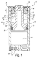
図1は、本発明の第1の実施形態に係る、ピストンステムの飛び出しを制御しうる安全装置を備えたガスシリンダアクチュエータ10の縦断面図である。
FIG. 1 is a longitudinal sectional view of a
アクチュエータ10は、ガス充填バルブ13が付設された底部12と、ピストンステム15を通す孔が設けられたヘッド部14とを有する、ガスを封じ込めるための管状のジャケット11を備えている。
The
ジャケット11、底部12およびピストンヘッド16は、ガス圧縮・膨張チャンバ17を区画し、他方、ジャケット11、ピストンヘッド16およびヘッド部14は、ピストンヘッド16のストロークチャンバ18を区画する。
The
長手のガスシリンダアクチュエータ10は、ヘッド部14とジャケット11との固定部分19が位置する上方側において、ジャケット11の内面22に浅いレリーフが刻まれた領域(レリーフ帯)21を有している。ガスケット手段23は、ピストンヘッド16と関連づけられつつジャケット11の内面22に対して働き、ジャケット11の密閉を保つが、他方、レリーフ帯21は、この密閉を破るために設けられている。
The longitudinal
すなわち、レリーフ帯21は、ピストンヘッド16がジャケット11から完全に押し出される前に、加圧ガスをガスチャンバ17から逃がす。
That is, the
ジャケット11は、横方向の断面積が小さい肉薄領域20を有している。この肉薄領域20は、多くの試験の結果、ヘッド部14と関連づけられたピストンヘッド16の強度を超える衝撃を受けたときには、最も破断しやすい箇所と分かっている。
The
レリーフ帯21においては、一連の凹部24が、ジャケット11の内面22の同一周上に、弧を描くように横方向に並べて設けられている。
In the
図示しない変形例として、レリーフ帯は、ジャケット11の内面22に設けられた施条、または内面22の同一周上に形成された環状の溝から形成することもできる。
As a modification (not shown), the relief band may be formed from a ridge provided on the
上記第1の実施形態においては、ヘッド部14は、閉止リング26からなる。閉止リング26は、環状体25におけるねじ山付きの鍔27に螺着されることにより環状体25に固定される。
In the first embodiment, the
環状体25は、係止リング29を介して、ジャケット11に保持される。係止リング29は、ジャケット11の上端31付近の内面22に設けられた環状のくぼみ30に嵌め込まれる。係止リング29は、くぼみ30の反対側においては、環状体25のショルダー部33に対して押圧される。
The
ガスケット手段23は、断面逆V字形の封止リング28からなっている。
The gasket means 23 comprises a
封止リング28は、アクチュエータ10が通常の作動を行っている間は、ジャケット11の内面22に対して押圧され、内部を密封する。
The
ジャケット11は、係止リング29用の環状のくぼみ30と、環状の外側凹部36との間に、断面積が小さい肉薄領域20を有している。
The
ピストンヘッド16とピストンステム15の境界領域38は、比較的大きい曲率半径を有し破断しにくくなっているため、ピストンと環状体25との間に衝撃が加わったり、不測の負荷がかかったりした場合には、ジャケット11の上端31の方が破断する。
Since the
図2に示すように、ピストンと環状体25の間に衝撃が加わったり、不測の負荷がかかったりすると、ピストンは、加圧ガスによって上方へ推進され、ガスケット手段である封止リング28が一連の凹部24(レリーフ帯21)に到達するまで、ジャケットの外側方向へ向かって移動する。
As shown in FIG. 2, when an impact is applied between the piston and the
封止リング28が凹部24に到達すると、ピストン下方のガスチャンバに充満していた加圧ガスは、封止リング28と凹部24との間に生じる抜け道を通ってジャケットの外部へ放出され、ピストンの上昇速度は急激に減少する。したがって、環状体25に対するピストンの衝撃エネルギーは失われる。
When the sealing
このため、図3に示すように、ピストンヘッド16とピストンステム15は、ジャケット11の破断によって外部に露出することはあっても、移動の速度は小さいために、危険ではない。
For this reason, as shown in FIG. 3, the
レリーフ帯21は、ピストンステム15とピストンヘッド16が、制御されない状態で飛び出すおそれがある状況下で、アクチュエータ10の安全性を確保しうるよう、ピストンステムが外部に露出する場合でも、その速度を制御するための機構となっている。
The
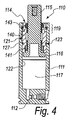
図4〜図7は、本発明の第2の実施形態に係る、ピストンステムの飛び出しを制御しうる安全装置を備えたガスシリンダアクチュエータ110を示す。
FIGS. 4-7 shows the
アクチュエータ110は、ジャケット111、ガス充填バルブ113が付設された底部112、ヘッド部114、およびガスチャンバ117を備えている。ヘッド部114は、ピストンステム115が通る孔と同一の方向に延びるスリーブ140からなる。
The
図4(詳細は図5)に示すように、スリーブ140に関連するシール手段123は、ピストンステム115に動的シールを与える内側の封止リング141、および外側の静的シールリング127からなっている。静的シールリング127は、ジャケット111の内面122に対して押圧される。
As shown in FIG. 4 (detailed in FIG. 5), the sealing means 123 associated with the
スリーブ140は、固定領域119において、飛び出し防止リング143を介して、ジャケット111の内側に止着されている。飛び出し防止リング143は、2つの相対向する第1のショルダー144(スリーブ140の外面に設けられている)と第2のショルダー145(ジャケット111の内面122に設けられている)の間に位置している。
The
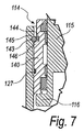
突然過大な負荷(例えばピストンステム15が制御されずに復帰する等)がかかると、図6(詳細は図7)に示すように、第1のショルダー144は破損し、スリーブ140(ガスによってジャケットの外側へ推進される)は上昇して、静的シールリング127(ジャケット111の内面122に対して働く)をレリーフ帯121へ押しやる。この結果、スリーブ140と関連づけられたガスケット手段123、特に静的シールリング127(ジャケット111の内面122に対して働く)によって実現されていた密封は、レリーフ帯121を介して破られる。
When suddenly an excessive load (for example, the piston stem 15 returns without being controlled), the
第1のショルダー144は、片持ち梁となっているため、所定の降伏点がある。
Since the
スリーブ140は、飛び出し防止リング143の内径よりも大きい外径をもつ第3のショルダー146を備えている。ピストンが衝撃を受けても、飛び出し防止リング143が、第3のショルダー146によって係止されるならば、スリーブ140がジャケット111から外に飛び出すのは防止される。
The
レリーフ帯121は、ジャケット111の内面122の同一周上に設けられる一連のくぼみ、または環状の溝から形成される。
The
図8〜図10は、本発明の第3の実施形態に係るガスシリンダアクチュエータ210を示す。
8 to 10 show a
アクチュエータ210は、ジャケット211、ガス充填バルブ213が付設された底部212、ヘッド部214、およびガスチャンバ217を備えている。ヘッド部214は、環状体225および閉止リング226から形成されている。閉止リング226は、環状体225の対応するねじ山付き鍔227に螺合されて、環状体225に固着される。
The
環状体225は、ロックリング229を介して、ジャケット211に対して保持されている。ロックリング229は、固定領域219(ジャケットの上端231の近傍)において、ジャケット211の内面222に形成された環状の溝230に嵌め合わされる。
The
ロックリング229は、反対側(内側)においては、環状体225に形成された環状のくぼみ233に押し込まれる。
On the opposite side (inner side), the
ガスケット手段223は、ピストンステム215に連なるピストンヘッド216に嵌め込まれた、断面逆V字形の封止リング288からなっている。
The gasket means 223 is composed of a sealing ring 288 having an inverted V-shaped cross section fitted into a
封止リング228は、ガスシリンダアクチュエータ210が通常の作動をしている間は、ジャケット211の内面222に対して押圧され、内部を密封する。
During the normal operation of the
封止リング28は、アクチュエータ10が通常の作動を行っている間は、ジャケット11の内面22に対して押圧される。
The sealing
環状体225の第1のショルダー244は、環状体225を一周りするくぼみ233の下方部分を形成する片持ち梁である。
The
他方、環状体225の第2のショルダー246は、ピストンの行程を狭めるために、第1のショルダー244よりも下方に形成されている。
On the other hand, the
図9に示すように、第1のショルダー244が破損すると、環状体225は、加圧ガスによって推進されたピストンヘッド216によって押し上げられ、第2のショルダー246がロックリング299に当接する。この結果、図10に示すように、封止リング228は、レリーフ帯221に到達する。この状態になると、レリーフ帯221は、ガスケット手段223(すなわち封止リング228)がジャケット211の内面222に対して働くことによって実現されていた密閉を破る。
As shown in FIG. 9, when the
第1のショルダー244は、片持ち梁となっているため、所定の降伏点がある。
Since the
第2のショルダー246の外径は、ロックリング229の内径よりも大きい。したがって、ピストンが衝撃を受けても、ロックリング229が、第2のショルダー246を係止するため、環状体225がジャケット111から外に飛び出すのは防止される。
The outer diameter of the
レリーフ帯121は、ジャケット111の内面122の同一周上に設けられる一連のくぼみ、または環状の溝から形成される。
The
レリーフ帯221は、ジャケットの内面222の同一周上に配置された一連の凹部または内面222に形成された環状の溝である。
The
上記3つの実施形態に係るガスシリンダアクチュエータを稼働させてみたところ、所期の目的を達成することが確認された。 When the gas cylinder actuators according to the above three embodiments were operated, it was confirmed that the intended purpose was achieved.
上記3つ実施形態に係るアクチュエータ10,110,210は、それぞれ、レリーフ帯21,121,221が存在するために、加圧ガスを安全に逃がすことができる。よって、ピストンステム15,115,215が、制御されない状態で飛び出す事態は防止される。
The
以上説明したように、本発明によれば、ガス圧縮・膨張チャンバ17,117,217に過大な圧力が生じても、ピストンステム16,116,216が制御されずにジャケットから飛び出すことはない。これは、一つには、ガスシリンダアクチュエータが、ピストンをジャケット内で上昇させるような衝撃を受けても、ピストンヘッド16,216,216、およびピストンステム15,115,215が、これに抵抗するためである。もう一つには、肉薄領域20、スリーブ140の第1のショルダー144等が破壊され、ピストンやスリーブが押しとどめられることなく行程を続けることにより、封止リング23,123,223が、それぞれ、レリーフ帯21,121,221に到達し、加圧ガスが放出されて、ピストンステムの飛び出し速度が急激に減少するためである。
As described above, according to the present invention, even if an excessive pressure is generated in the gas compression /
また、本発明によれば、ピストンステムの制御されない飛び出しを防止しつつ、性能も、公知の安全装置付きガスシリンダアクチュエータに劣ることのない、ガスシリンダアクチュエータが提供される。 Further, according to the present invention, there is provided a gas cylinder actuator that prevents the piston stem from being uncontrolled and that is not inferior to a known gas cylinder actuator with a safety device.
さらに、本発明のガスシリンダアクチュエータは、特別な調整をしなくても公知の機械や設備に容易に装着することができる。 Furthermore, the gas cylinder actuator of the present invention can be easily mounted on a known machine or facility without any special adjustment.
最後に、本発明によれば、構造が簡単で、かつ公知のシステムと技術を使って低コストで製造しうる、ピストンステムの制御されない飛び出しを防止しうるガスシリンダアクチュエータが提供される。 Finally, the present invention provides a gas cylinder actuator that is simple in construction and that can be manufactured at low cost using known systems and techniques and that can prevent uncontrolled popping of the piston stem.
本発明については、特許請求の範囲に記載した範囲内で、多くの設計変更や変形例を施すことができる。また、細部にわたる技術的な事項は、他の技術的に等価な要素で置き換えることができる。 Many design changes and modifications can be made to the present invention within the scope described in the claims. In addition, technical matters in detail can be replaced with other technically equivalent elements.
実際には、本発明に用いる材料、所定の形状および大きさは、用途に適合しうるものである限り、現場での要求やその時々の技術水準に応じて、どのようなものにも変更することができる。 In practice, the material, predetermined shape and size used in the present invention can be changed according to the requirements in the field and the state of the art as long as it can be adapted to the application. be able to.
イタリア国特許出願PD2009A000100号(本願は、この出願に基づく優先権を主張している)の明細書に記載した内容は、そのすべてを本明細書において引用する。 The contents described in the specification of Italian Patent Application No. PD2009A000100 (which claims priority based on this application) are hereby incorporated by reference in their entirety.
特許請求の範囲における発明特定事項には符号を付してあるが、この符号は、請求項の記載を分かりやすくすることのみを目的とするものであり、発明特定事項の解釈に限定を加える趣旨ではない。 The invention-specific matters in the claims are marked with symbols, but these symbols are only intended to make the description of the claims easier to understand and are intended to limit the interpretation of the invention-specific matters. is not.
Claims (8)
前記ジャケット(11,111,211)、底部(12,112,212)およびピストンヘッド(16,116,216)は、ガス圧縮・膨張チャンバ(17,117,217)を区画し、
ヘッド部(14,114,214)をジャケット(11,111,211)に固定するための領域(19,119)において、ジャケット(11,111,211)の内面(22,122,222)にレリーフ帯(21,121,221)を有し、
このレリーフ帯(21,121,221)は、通常の稼働時にはジャケット(11,111,211)の内面(22,122,222)に対して働く、ピストンヘッド(16,216)と関連づけられたガスケット手段(23,223)、またはヘッド部(114)と関連づけられたガスケット手段(123)によって実現される密閉を、ジャケットの外側へ向かうピストンヘッド(16,116,216)の動きとともに、ヘッド部(14,114,214)がジャケットから外れようとする際には、破るようになっているガスシリンダアクチュエータにおいて、
前記底部(12,112,212)にはガス充填バルブ(13,113,213)が付設されており、
前記ヘッド部(14)は、ねじ山付きの鍔(27)を有する環状体(25)、および前記鍔(27)に螺合されて環状体(25)に固定される閉止リング(26)からなり、
前記環状体(25)は、ジャケット(11)の端部(31)の近傍において、このジャケット(11)の内面(22)に設けられる環状のみぞ(30)に嵌め合わされ、反対側においては、環状体(25)に形成された環状のくぼみ(33)に対して押圧されるロックリング(29)によってジャケット(11)に保持されるようになっていることを特徴とするガスシリンダアクチュエータ。 A gas cylinder actuator (10, 110, 210) with a safety device for controlling the protrusion of a piston stem, one end of which is a bottom (12, 112, 212) and the other end is a piston head (16, 116, 216) are tubular jackets for containing gas, each of which is hermetically sealed by a head portion (14, 114, 214) provided with a hole for passing a piston stem (15, 115, 215). 11, 111, 211),
The jacket (11, 111, 211), the bottom (12, 112, 212) and the piston head (16, 116, 216) define a gas compression / expansion chamber (17, 117, 217),
Relief on the inner surface (22, 122, 222) of the jacket (11, 111, 211) in the region (19, 119) for fixing the head portion (14, 114, 214) to the jacket (11, 111, 211). With belts (21, 121, 221),
This relief band (21, 121, 221) is a gasket associated with the piston head (16, 216) that acts against the inner surface (22, 122, 222) of the jacket (11, 111, 211) during normal operation. The sealing realized by the means (23, 223) or the gasket means (123) associated with the head (114), together with the movement of the piston head (16, 116, 216) towards the outside of the jacket, 14, 114, 214) in a gas cylinder actuator that is designed to break when it is about to be removed from the jacket,
Gas filling valves (13, 113, 213) are attached to the bottom (12, 112, 212),
The head portion (14) includes an annular body (25) having a threaded collar (27), and a closing ring (26) that is screwed to the collar (27) and fixed to the annular body (25). Become
The annular body (25) is fitted into an annular groove (30) provided on the inner surface (22) of the jacket (11) in the vicinity of the end (31) of the jacket (11), and on the opposite side, A gas cylinder actuator characterized in that it is held in a jacket (11) by a lock ring (29) pressed against an annular recess (33) formed in the annular body (25) .
前記ジャケット(11,111,211)、底部(12,112,212)およびピストンヘッド(16,116,216)は、ガス圧縮・膨張チャンバ(17,117,217)を区画し、The jacket (11, 111, 211), the bottom (12, 112, 212) and the piston head (16, 116, 216) define a gas compression / expansion chamber (17, 117, 217),
ヘッド部(14,114,214)をジャケット(11,111,211)に固定するための領域(19,119)において、ジャケット(11,111,211)の内面(22,122,222)にレリーフ帯(21,121,221)を有し、Relief on the inner surface (22, 122, 222) of the jacket (11, 111, 211) in the region (19, 119) for fixing the head portion (14, 114, 214) to the jacket (11, 111, 211). With belts (21, 121, 221),
このレリーフ帯(21,121,221)は、通常の稼働時にはジャケット(11,111,211)の内面(22,122,222)に対して働く、ピストンヘッド(16,216)と関連づけられたガスケット手段(23,223)、またはヘッド部(114)と関連づけられたガスケット手段(123)によって実現される密閉を、ジャケットの外側へ向かうピストンヘッド(16,116,216)の動きとともに、ヘッド部(14,114,214)がジャケットから外れようとする際には、破るようになっているガスシリンダアクチュエータにおいて、This relief band (21, 121, 221) is a gasket associated with the piston head (16, 216) that acts against the inner surface (22, 122, 222) of the jacket (11, 111, 211) during normal operation. The sealing realized by the means (23, 223) or the gasket means (123) associated with the head (114), together with the movement of the piston head (16, 116, 216) towards the outside of the jacket, 14, 114, 214) in a gas cylinder actuator that is designed to break when it is about to be removed from the jacket,
前記底部(12,112,212)にはガス充填バルブ(13,113,213)が付設されており、Gas filling valves (13, 113, 213) are attached to the bottom (12, 112, 212),
前記ヘッド部(114)は、ピストンステム(115)が通る孔と同一の方向に延びるスリーブ(140)からなり、The head portion (114) comprises a sleeve (140) extending in the same direction as the hole through which the piston stem (115) passes,
前記スリーブ(140)は、ピストンステム(115)に動的シールを与える内側の封止リング(141)、およびジャケット(111)の内面(122)に対して押圧される、外側の静的シールリング(127)からなり、かつスリーブ(140)の外面に設けられた第1のショルダー(144)と、ジャケット(111)の内面(122)に設けられた第2のショルダー(145)の間に位置する飛び出し防止リング(143)を介して、ジャケット(111)の内側に止着され、The sleeve (140) has an inner sealing ring (141) that provides a dynamic seal to the piston stem (115) and an outer static seal ring that is pressed against the inner surface (122) of the jacket (111). (127) and located between the first shoulder (144) provided on the outer surface of the sleeve (140) and the second shoulder (145) provided on the inner surface (122) of the jacket (111) Is attached to the inside of the jacket (111) via the pop-out prevention ring (143),
前記レリーフ帯(121)は、第1のショルダー(144)が破損し、スリーブ(140)が加圧ガスによってジャケットの外側へ推進され、上昇して、静的シールリング(127)をレリーフ帯121へ押し上げたときに、スリーブ(140)と関連づけられたガスケット手段(123)、またはジャケット(111)の内面(122)に対して働く静的シールリング(127)によって実現されていた密閉を破るようになっていることを特徴とするガスシリンダアクチュエータ。In the relief band (121), the first shoulder (144) is broken, and the sleeve (140) is pushed to the outside of the jacket by the pressurized gas, and then rises, so that the static seal ring (127) is moved to the relief band 121. When pushed up to break the seal provided by the gasket means (123) associated with the sleeve (140) or the static seal ring (127) acting against the inner surface (122) of the jacket (111) A gas cylinder actuator characterized by
Applications Claiming Priority (3)
| Application Number | Priority Date | Filing Date | Title |
|---|---|---|---|
| ITPD2009A000100A IT1393971B1 (en) | 2009-04-21 | 2009-04-21 | GAS SPRING WITH SAFETY DEVICE FOR THE PISTON STEM CONTROLLED |
| ITPD2009A000100 | 2009-04-21 | ||
| PCT/EP2010/054982 WO2010121946A1 (en) | 2009-04-21 | 2010-04-15 | Gas cylinder actuator with safety system for controlled ejection of the piston stem |
Publications (2)
| Publication Number | Publication Date |
|---|---|
| JP2012524875A JP2012524875A (en) | 2012-10-18 |
| JP5480366B2 true JP5480366B2 (en) | 2014-04-23 |
Family
ID=41228217
Family Applications (1)
| Application Number | Title | Priority Date | Filing Date |
|---|---|---|---|
| JP2012506448A Active JP5480366B2 (en) | 2009-04-21 | 2010-04-15 | Gas cylinder actuator with a safety device that can control the protrusion of the piston stem |
Country Status (9)
| Country | Link |
|---|---|
| US (1) | US9157500B2 (en) |
| EP (1) | EP2243976B1 (en) |
| JP (1) | JP5480366B2 (en) |
| KR (1) | KR101663144B1 (en) |
| CN (1) | CN102405360B (en) |
| BR (1) | BRPI1013414B1 (en) |
| ES (1) | ES2557677T3 (en) |
| IT (1) | IT1393971B1 (en) |
| WO (1) | WO2010121946A1 (en) |
Families Citing this family (20)
| Publication number | Priority date | Publication date | Assignee | Title |
|---|---|---|---|---|
| ES2684688T3 (en) * | 2012-03-01 | 2018-10-04 | Special Springs S.R.L. | Gas cylinder actuator with overcurrent safety device |
| CN103375455B (en) * | 2012-04-24 | 2015-12-02 | 东莞市欣悦模具有限公司 | A kind of transfer bar mechanism |
| FR3003327B1 (en) | 2013-03-13 | 2015-07-31 | Eurocopter France | SHUT OFF DEVICE OF A HYDRAULIC SYSTEM HYDRAULIC SYSTEM AND AIRCRAFT |
| US9551394B2 (en) | 2013-03-15 | 2017-01-24 | Dadco, Inc. | Overtravel pressure relief for a gas spring |
| US9347510B2 (en) | 2013-03-15 | 2016-05-24 | Dadco, Inc. | Overtravel pressure relief for a gas spring |
| US9447834B2 (en) | 2013-09-19 | 2016-09-20 | Dadco, Inc. | Overtravel pressure relief for a gas spring |
| SE1450765A1 (en) | 2014-06-19 | 2015-12-20 | Strömsholmen Ab | Gas spring and safety procedure for gas spring |
| CN105276057B (en) * | 2014-07-04 | 2019-12-17 | 宁波裕盛家居科技有限公司 | Pneumatic damping buffer |
| US20160250770A1 (en) * | 2015-02-27 | 2016-09-01 | Special Springs S.R.L. | Gas-actuated hold-down for punching devices and punching device with such hold-down |
| ITUB20159608A1 (en) * | 2015-12-21 | 2017-06-21 | Special Springs Srl | GAS SPRING WITH EXTRA-RUN SAFETY DEVICE |
| ITUB20159302A1 (en) * | 2015-12-21 | 2017-06-21 | Special Springs Srl | GAS SPRING WITH SAFETY DEVICE FOR UNCONTROLLED RETURN OF THE STELO-PISTON |
| ES2638539B1 (en) * | 2016-04-18 | 2018-07-31 | Nitrogas Group, S.L. | Gas cylinder |
| SE541568C2 (en) * | 2016-06-22 | 2019-11-05 | Stroemsholmen Ab | Piston cylinder device with protection arrangement and method of protecting a piston cylinder device against overload or failure of the piston cylinder device |
| ITUA20164635A1 (en) * | 2016-06-24 | 2017-12-24 | Special Springs Srl | GAS SPRING WITH SAFETY DEVICE |
| US10113605B2 (en) * | 2016-09-29 | 2018-10-30 | Dadco, Inc. | Overtravel relief assembly for a gas spring |
| EP3364066B1 (en) * | 2017-02-17 | 2020-06-24 | Special Springs S.r.l. | Gas cylinder actuator with safety device for uncontrolled return of the piston-stem |
| DE102017103925A1 (en) * | 2017-02-24 | 2018-08-30 | Thyssenkrupp Ag | Locking package, vibration damper and use of a seal holder |
| GB2566332B (en) * | 2017-09-12 | 2019-12-11 | Metrol Springs Ltd | Seal housing |
| WO2021096845A1 (en) * | 2019-11-12 | 2021-05-20 | Joyson Safety Systems Acquisition Llc | Energy damping linear actuator |
| CA3131743A1 (en) * | 2020-10-20 | 2022-04-20 | Special Springs S.R.L. | Gas-filled cylinder with overtravel safety device |
Family Cites Families (10)
| Publication number | Priority date | Publication date | Assignee | Title |
|---|---|---|---|---|
| CA2028573A1 (en) * | 1989-11-08 | 1991-05-09 | Bernard Joseph Wallis | Gas spring |
| DE4101567A1 (en) * | 1991-01-21 | 1992-07-23 | Stabilus Gmbh | ADJUSTMENT |
| JPH07158612A (en) * | 1993-10-01 | 1995-06-20 | Ckd Corp | Rodless cylinder |
| US6086059A (en) | 1998-02-13 | 2000-07-11 | Strolsholmen Ab | Gas spring device |
| FR2778956B1 (en) * | 1998-05-22 | 2000-08-04 | Orflam Ind | GAS SPRING INCORPORATING A SAFETY MEMBER |
| US6199838B1 (en) * | 1998-10-27 | 2001-03-13 | Diebolt International, Inc. | Gas spring filler valve |
| AT414033B (en) * | 2001-01-09 | 2006-08-15 | Blum Gmbh Julius | DAMPERS, ESPECIALLY FOR FURNITURE |
| DE10325357B4 (en) * | 2003-06-05 | 2005-08-04 | Schuler Pressen Gmbh & Co. Kg | Pneumatic force generating device with safety device |
| JP2005291470A (en) * | 2004-04-05 | 2005-10-20 | Nhk Spring Co Ltd | Gas cushion device |
| DE102004026356B4 (en) * | 2004-05-26 | 2008-07-31 | Stabilus Gmbh | tension spring |
-
2009
- 2009-04-21 IT ITPD2009A000100A patent/IT1393971B1/en active
-
2010
- 2010-04-15 WO PCT/EP2010/054982 patent/WO2010121946A1/en active Application Filing
- 2010-04-15 KR KR1020117027390A patent/KR101663144B1/en active IP Right Grant
- 2010-04-15 CN CN201080018139.9A patent/CN102405360B/en active Active
- 2010-04-15 US US13/138,882 patent/US9157500B2/en active Active
- 2010-04-15 EP EP10160032.8A patent/EP2243976B1/en active Active
- 2010-04-15 ES ES10160032.8T patent/ES2557677T3/en active Active
- 2010-04-15 BR BRPI1013414-0A patent/BRPI1013414B1/en active IP Right Grant
- 2010-04-15 JP JP2012506448A patent/JP5480366B2/en active Active
Also Published As
| Publication number | Publication date |
|---|---|
| EP2243976B1 (en) | 2015-09-23 |
| JP2012524875A (en) | 2012-10-18 |
| CN102405360B (en) | 2014-01-01 |
| BRPI1013414B1 (en) | 2020-07-07 |
| ITPD20090100A1 (en) | 2010-10-22 |
| US9157500B2 (en) | 2015-10-13 |
| EP2243976A1 (en) | 2010-10-27 |
| KR20120007053A (en) | 2012-01-19 |
| IT1393971B1 (en) | 2012-05-17 |
| ES2557677T3 (en) | 2016-01-27 |
| KR101663144B1 (en) | 2016-10-06 |
| BRPI1013414A2 (en) | 2016-04-05 |
| WO2010121946A1 (en) | 2010-10-28 |
| US20120042770A1 (en) | 2012-02-23 |
| CN102405360A (en) | 2012-04-04 |
Similar Documents
| Publication | Publication Date | Title |
|---|---|---|
| JP5480366B2 (en) | Gas cylinder actuator with a safety device that can control the protrusion of the piston stem | |
| EP2406520B1 (en) | Gas cylinder actuator with overtravel safety device | |
| US9726287B2 (en) | Gas cylinder actuator with overtravel safety device | |
| US9593734B2 (en) | Gas-operated spring | |
| US10619695B2 (en) | Gas cylinder actuator with safety device | |
| EP3184847B1 (en) | Gas cylinder actuator with safety device | |
| EP3184848B1 (en) | Gas cylinder actuator with overtravel safety device | |
| US10907663B2 (en) | Gas cylinder actuator with overtravel indicator device |
Legal Events
| Date | Code | Title | Description |
|---|---|---|---|
| A621 | Written request for application examination |
Free format text: JAPANESE INTERMEDIATE CODE: A621 Effective date: 20130131 |
|
| A977 | Report on retrieval |
Free format text: JAPANESE INTERMEDIATE CODE: A971007 Effective date: 20131227 |
|
| TRDD | Decision of grant or rejection written | ||
| A01 | Written decision to grant a patent or to grant a registration (utility model) |
Free format text: JAPANESE INTERMEDIATE CODE: A01 Effective date: 20140115 |
|
| A61 | First payment of annual fees (during grant procedure) |
Free format text: JAPANESE INTERMEDIATE CODE: A61 Effective date: 20140213 |
|
| R150 | Certificate of patent or registration of utility model |
Ref document number: 5480366 Country of ref document: JP Free format text: JAPANESE INTERMEDIATE CODE: R150 |
|
| R250 | Receipt of annual fees |
Free format text: JAPANESE INTERMEDIATE CODE: R250 |
|
| R250 | Receipt of annual fees |
Free format text: JAPANESE INTERMEDIATE CODE: R250 |
|
| R250 | Receipt of annual fees |
Free format text: JAPANESE INTERMEDIATE CODE: R250 |
|
| R250 | Receipt of annual fees |
Free format text: JAPANESE INTERMEDIATE CODE: R250 |
|
| R250 | Receipt of annual fees |
Free format text: JAPANESE INTERMEDIATE CODE: R250 |
|
| R250 | Receipt of annual fees |
Free format text: JAPANESE INTERMEDIATE CODE: R250 |
|
| R250 | Receipt of annual fees |
Free format text: JAPANESE INTERMEDIATE CODE: R250 |
|
| R250 | Receipt of annual fees |
Free format text: JAPANESE INTERMEDIATE CODE: R250 |