JP2005291470A - Gas cushion device - Google Patents
Gas cushion device Download PDFInfo
- Publication number
- JP2005291470A JP2005291470A JP2004111301A JP2004111301A JP2005291470A JP 2005291470 A JP2005291470 A JP 2005291470A JP 2004111301 A JP2004111301 A JP 2004111301A JP 2004111301 A JP2004111301 A JP 2004111301A JP 2005291470 A JP2005291470 A JP 2005291470A
- Authority
- JP
- Japan
- Prior art keywords
- cylinder
- rod
- seal
- peripheral surface
- gas
- Prior art date
- Legal status (The legal status is an assumption and is not a legal conclusion. Google has not performed a legal analysis and makes no representation as to the accuracy of the status listed.)
- Pending
Links
- 230000002093 peripheral effect Effects 0.000 claims abstract description 79
- 239000004519 grease Substances 0.000 claims description 83
- 239000000428 dust Substances 0.000 claims description 58
- 230000001629 suppression Effects 0.000 claims description 33
- 238000005461 lubrication Methods 0.000 claims description 9
- JOYRKODLDBILNP-UHFFFAOYSA-N Ethyl urethane Chemical compound CCOC(N)=O JOYRKODLDBILNP-UHFFFAOYSA-N 0.000 claims description 5
- 239000007789 gas Substances 0.000 abstract description 142
- 238000007789 sealing Methods 0.000 abstract description 12
- IJGRMHOSHXDMSA-UHFFFAOYSA-N Atomic nitrogen Chemical compound N#N IJGRMHOSHXDMSA-UHFFFAOYSA-N 0.000 abstract description 4
- 229910052757 nitrogen Inorganic materials 0.000 abstract description 2
- 230000001050 lubricating effect Effects 0.000 description 19
- 239000007788 liquid Substances 0.000 description 18
- 239000000463 material Substances 0.000 description 8
- 230000004308 accommodation Effects 0.000 description 4
- 238000005452 bending Methods 0.000 description 2
- 239000011261 inert gas Substances 0.000 description 2
- 239000002184 metal Substances 0.000 description 2
- 239000011347 resin Substances 0.000 description 2
- 229920005989 resin Polymers 0.000 description 2
- 229920001169 thermoplastic Polymers 0.000 description 2
- 229920002803 thermoplastic polyurethane Polymers 0.000 description 2
- 230000037303 wrinkles Effects 0.000 description 2
- 230000015572 biosynthetic process Effects 0.000 description 1
- 230000020169 heat generation Effects 0.000 description 1
- 239000000314 lubricant Substances 0.000 description 1
- 239000010687 lubricating oil Substances 0.000 description 1
- 239000003921 oil Substances 0.000 description 1
- 230000001105 regulatory effect Effects 0.000 description 1
- 238000007790 scraping Methods 0.000 description 1
- 229920001187 thermosetting polymer Polymers 0.000 description 1
Images


Landscapes
- Sealing With Elastic Sealing Lips (AREA)
- Sealing Devices (AREA)
- Fluid-Damping Devices (AREA)
- Presses And Accessory Devices Thereof (AREA)
- Shaping Metal By Deep-Drawing, Or The Like (AREA)
Abstract
【課題】本発明は、高い初期荷重を維持しつつ小型化できるガスクッション装置を提供する。
【解決手段】ガスクッション装置10は、圧縮された窒素が封入された気室34を備えたシリンダ30と、シリンダ30の内部に挿入され、シリンダ30に対して軸線方向に移動可能なロッド40と、シリンダ30とロッド40との摺動部分をシールするシール部50とを備える。シール部50は、シリンダ30の内周面に形成された高圧シール収容溝61と、高圧シール収容溝61に収容されかつロッド40に密接する高圧シール62と、シリンダ30の内周面に設けられロッド40を支持する軸受部70とを備える。軸受部70は、シリンダ30の内周面において、高圧シール収容溝61を挟んでロッド40の軸線方向に沿う両側近傍にそれぞれ設けられる。
【選択図】 図3The present invention provides a gas cushion device that can be miniaturized while maintaining a high initial load.
A gas cushion device includes a cylinder having an air chamber filled with compressed nitrogen, and a rod inserted into the cylinder and movable in an axial direction with respect to the cylinder. And a seal portion 50 for sealing a sliding portion between the cylinder 30 and the rod 40. The seal part 50 is provided on the inner peripheral surface of the cylinder 30, the high-pressure seal receiving groove 61 formed on the inner peripheral surface of the cylinder 30, the high-pressure seal 62 received in the high-pressure seal receiving groove 61 and in close contact with the rod 40. And a bearing portion 70 that supports the rod 40. The bearing portions 70 are provided in the vicinity of both sides along the axial direction of the rod 40 with the high-pressure seal housing groove 61 interposed therebetween on the inner peripheral surface of the cylinder 30.
[Selection] Figure 3
Description
本発明は、例えばガス封入式ダイスプリングなどのように、内部に高圧ガスが封入されるガスクッション装置に関する。 The present invention relates to a gas cushion device in which high-pressure gas is sealed inside, such as a gas-filled die spring.
プレス装置において、素板を絞り加工する場合などに、ダイスプリングが用いられている。ダイスプリングには、ガスクッション装置が用いられている(例えば、特許文献1参照。)。 In a press device, a die spring is used when drawing a base plate. A gas cushion device is used for the die spring (see, for example, Patent Document 1).
ガスクッション装置は、内部に高圧ガスが封入される気室を備えるシリンダと、シリンダの内部に挿入され軸線方向に移動可能なロッドと、気室内のガス漏れを抑制する軸封アッセンブリとを備えている。軸封アッセンブリは、潤滑油などの液が収容される液室と、第1のシール部と、第2のシール部と、ダストシールと、バックアップシールと、ベアリングとを備えている。 The gas cushion device includes a cylinder including an air chamber in which high-pressure gas is sealed, a rod that is inserted into the cylinder and is movable in an axial direction, and a shaft seal assembly that suppresses gas leakage in the air chamber. Yes. The shaft seal assembly includes a liquid chamber in which a liquid such as lubricating oil is accommodated, a first seal portion, a second seal portion, a dust seal, a backup seal, and a bearing.
液室は、シリンダの内周面に形成されている。第1のシール部は、液室とシリンダの開口端との間に設けられている。第2のシール部は、液室と気室との間に設けられている。ダストシールは、第1のシール部とシリンダの開口端との間に設けられている。バックアップシールは、第2のシール部と気室との間に設けられている。ベアリングは、液室と第2のシール部との間に設けられている。 The liquid chamber is formed on the inner peripheral surface of the cylinder. The first seal portion is provided between the liquid chamber and the opening end of the cylinder. The second seal portion is provided between the liquid chamber and the air chamber. The dust seal is provided between the first seal portion and the opening end of the cylinder. The backup seal is provided between the second seal portion and the air chamber. The bearing is provided between the liquid chamber and the second seal portion.
液室の液は、気室内のガスがロッドの移動に伴ってシリンダの開口端の方向へ漏れることを抑制するとともにロッドの摺動部分を潤滑する。第1のシール部は、液室内の液がシリンダの開口端の方向へ漏れることを抑制している。第2のシール部は、液室内の液が気室内に漏れることを抑制している。 The liquid in the liquid chamber suppresses the gas in the air chamber from leaking toward the opening end of the cylinder as the rod moves, and lubricates the sliding portion of the rod. The first seal portion suppresses the liquid in the liquid chamber from leaking toward the opening end of the cylinder. The second seal portion suppresses the liquid in the liquid chamber from leaking into the air chamber.
また、第1のシール部は、ロッドとの摺動部分に液を含むことにより、液室を通過したガスがシリンダ外へ漏れることを抑制している。
近年、ガスクッション装置は、高い初期荷重を維持しつつ小型化が望まれている。しかし、ガスクッション装置を小型化するためにロッドを細くすると、気室内のガス封入圧力を高く設定しなければならない。なお、初期荷重とは、ロッドが気室内に向かって動き出す瞬間にロッドに加えられる荷重である。 In recent years, gas cushion devices are desired to be downsized while maintaining a high initial load. However, if the rod is thinned to reduce the size of the gas cushion device, the gas filling pressure in the air chamber must be set high. The initial load is a load applied to the rod at the moment when the rod starts to move into the air chamber.
また、ガスクッション装置は、プレスされる部品に対して、若干傾いた状態で取り付けられることがある。ガスクッション装置が傾いて取り付けられると、シリンダとロッドとの間に曲げ荷重が発生することによって、気室内のガスは、外部へ漏れる。このガス漏れは、気室内のガス封入圧力を高く設定するとより多くなると考えられる。ガスクッション装置は、ガスが漏れることによって、初期荷重が低減していく。 Further, the gas cushion device may be attached to the part to be pressed in a slightly inclined state. When the gas cushion device is attached at an angle, a bending load is generated between the cylinder and the rod, so that gas in the air chamber leaks to the outside. This gas leakage is considered to increase with a high gas filling pressure in the air chamber. In the gas cushion device, the initial load is reduced by gas leakage.
特許文献1に開示されているガスクッション装置では、小型化に伴いガス封入圧力をより高く設定すると、より多くのガスが液室を通過し第1のシール部に到達することが考えられる。 In the gas cushion device disclosed in Patent Document 1, if the gas filling pressure is set higher as the size of the gas cushion device is reduced, more gas may pass through the liquid chamber and reach the first seal portion.
第1のシール部は、ロッドとの摺動部分に液を含むことよってガス漏れも抑制するが、そもそも液室内の液漏れを抑制することを目的としているため、ガス封入圧力をより高く設定すると、ガスが第1のシール部とダストシールとを通過して外部へ漏れることが考えられる。 The first seal portion suppresses gas leakage by containing liquid in the sliding portion with the rod, but since it is intended to suppress liquid leakage in the liquid chamber in the first place, if the gas filling pressure is set higher It is conceivable that the gas passes through the first seal part and the dust seal and leaks to the outside.
したがって、本発明の目的は、高い初期荷重を維持しつつ小型化できるガスクッション装置を提供することにある。 Accordingly, an object of the present invention is to provide a gas cushion device that can be miniaturized while maintaining a high initial load.
本発明のガスクッション装置は、圧縮されたガスが封入される気室を内部に備えたシリンダと、シリンダの内部に挿入され、該シリンダに対して軸線方向に移動可能なロッドであって内端が気室内に位置し外端がシリンダの開口端から伸び出るロッドと、シリンダとロッドとの摺動部分をシールするシール部とを備える。シール部は、シリンダの内周面に形成される高圧シール収容溝と、高圧シール収容溝に収容されかつロッドの外周面に密接し、気室内のガスがシリンダから漏れることを抑制する高圧シールと、シリンダの内周面に設けられロッドを支持する軸受部であって高圧シール収容溝を挟んでロッドの軸線方向に沿う両側近傍にそれぞれ設けられる軸受部とを備える。 A gas cushion device according to the present invention includes a cylinder having an air chamber in which compressed gas is sealed, and a rod that is inserted into the cylinder and is movable in the axial direction with respect to the cylinder. Includes a rod whose outer end extends from the opening end of the cylinder and a seal portion that seals a sliding portion between the cylinder and the rod. The seal portion includes a high-pressure seal housing groove formed on the inner circumferential surface of the cylinder, a high-pressure seal that is housed in the high-pressure seal housing groove and is in close contact with the outer circumferential surface of the rod, and prevents gas in the air chamber from leaking from the cylinder. And a bearing portion provided on the inner peripheral surface of the cylinder for supporting the rod and provided in the vicinity of both sides along the axial direction of the rod across the high-pressure seal housing groove.
ガスクッション装置は、このような構造によって、高圧シールの近傍でのロッドの傾きおよび径方向への移動が抑えられるので、気室内のガス封入圧力を高く設定してもガスが漏れることが抑制される。 With such a structure, the gas cushion device can prevent the rod from tilting and moving in the radial direction in the vicinity of the high-pressure seal, so that gas leakage is suppressed even when the gas sealing pressure in the air chamber is set high. The
本発明の好ましい形態では、ガス漏れを一層抑制してガスクッション装置を小型化するために、高圧シールをウレタン製とする。 In a preferred embodiment of the present invention, the high-pressure seal is made of urethane in order to further suppress gas leakage and reduce the size of the gas cushion device.
本発明の好ましい形態では、ガスクッション装置の耐久性を向上するために、シール部が、該シール部およびシリンダとロッドとの摺動部分の潤滑を行う潤滑部を備える。潤滑部は、高圧シール収容溝とシリンダの開口端との間のシリンダの内周面に形成されるグリース収容室と、グリース収容室に収容されるグリースとを備える。 In a preferred embodiment of the present invention, in order to improve the durability of the gas cushion device, the seal portion includes a lubrication portion that lubricates the seal portion and a sliding portion between the cylinder and the rod. The lubrication unit includes a grease storage chamber formed on the inner peripheral surface of the cylinder between the high-pressure seal storage groove and the opening end of the cylinder, and grease stored in the grease storage chamber.
本発明の好ましい形態では、グリース漏れを抑制し、ガスクッション装置の耐久性を向上するために、シール部が、グリース漏れ抑制部を備える。グリース漏れ抑制部は、グリース収容室とシリンダの開口端との間のシリンダの内周面に形成されるグリース漏れ抑制溝と、グリース漏れ抑制溝に収容されかつロッドの外周面に密接しグリースがシリンダから漏れることを抑制するグリース漏れ抑制シールとを備える。グリース漏れ抑制部は、グリースがシリンダから漏れることを抑制する。 In a preferred embodiment of the present invention, the seal portion includes a grease leakage suppression portion in order to suppress grease leakage and improve the durability of the gas cushion device. The grease leakage suppression portion includes a grease leakage suppression groove formed on the inner peripheral surface of the cylinder between the grease storage chamber and the opening end of the cylinder, and is accommodated in the grease leakage suppression groove and in close contact with the outer peripheral surface of the rod. A grease leakage suppression seal that suppresses leakage from the cylinder. The grease leakage suppression unit suppresses grease from leaking from the cylinder.
本発明の好ましい形態では、シール部およびシリンダとロッドとの摺動部分へのダストの侵入を抑制するために、シール部がダストシール部を備える。ダストシール部は、グリース漏れ抑制溝とシリンダの開口端との間のシリンダの内周面に形成されるダストシール収容溝と、ダストシール収容溝に収容されかつロッドの外周面に密接しダストの侵入を抑制するダストシールとを備える。 In a preferred embodiment of the present invention, the seal portion includes a dust seal portion in order to suppress dust from entering the seal portion and the sliding portion between the cylinder and the rod. The dust seal part is housed in the dust seal housing groove formed on the inner peripheral surface of the cylinder between the grease leakage suppression groove and the opening end of the cylinder, and is in close contact with the outer peripheral surface of the rod and restrains dust from entering. A dust seal.
本発明に係るガスクッション装置によれば、気室内のガス封入圧力を高く設定しても、ガスがシリンダから漏れることが抑えられる。このため、ガスクッション装置は、高い初期荷重を維持しつつ小型化することができる。 According to the gas cushion device of the present invention, gas can be prevented from leaking from the cylinder even when the gas filling pressure in the air chamber is set high. For this reason, the gas cushion device can be miniaturized while maintaining a high initial load.
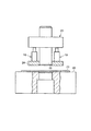
本発明の一実施形態に係るガスクッション装置について、図1から図7を参照して説明する。図1は、ガスクッション装置10が用いられるプレス装置20を示している。プレス装置20は、素板21に絞り加工を施す機能を有している。プレス装置20は、ダイス22と、ポンチ23と、素板21にしわが形成されることを防止するしわ押え部24と、ガスクッション装置10などを備えている。
A gas cushion device according to an embodiment of the present invention will be described with reference to FIGS. FIG. 1 shows a
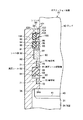
ガスクッション装置10は、図2に示すように、シリンダ30と、ロッド40と、シール部50とを備えている。
As shown in FIG. 2, the
シリンダ30は、内部にロッド40が挿入されて移動可能な中空部31を備える中空形状である。シリンダ30は、一端側に閉塞端32を備え、他端側に開口端33を備えている。シリンダ30は、内部に気室34を備えている。気室34は、シリンダ30の中空部31において、閉塞端32側に形成されている。気室34は、開口端33側の中空部31よりもシリンダ30を横切る方向に広く形成されている。気室34の開口部34aの周囲には、ストッパ壁部35が設けられている。
The
ロッド40は、シリンダ30の中空部31に軸線方向に移動可能に収容されている。ロッド40の内端部41は、気室34内に伸びている。ロッド40の外端部42は、シリンダ30の開口端33から外側へ伸び出ている。
The
ロッド40の内端部41は、外周面から外側へ広がるフランジ部43を備えている。ロッド40がシリンダ30から伸び出る方向に所定量移動すると、フランジ部43は、気室34のストッパ壁部35に当接する。このため、ロッド40の伸び側ストロークエンドが規制される。
The
気室34内には、不活性ガスが封入されている。不活性ガスの一例は、窒素である。ガスの封入圧力は、ガスクッション装置10に要求される反力に応じて決定される。本実施形態では、ガスの封入圧力は、例えば15MPa以上である。気室34内のガスの圧力は、ロッド40をシリンダ30から押し出す方向に作用している。
An inert gas is sealed in the
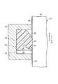
シール部50は、図3に示すように、ガスシール部60と、軸受部70と、潤滑部80と、グリース漏れ抑制部90と、ダストシール部100とを備えている。
As shown in FIG. 3, the
ガスシール部60は、気室34内のガスがシリンダ30から漏れることを抑制する機能を有している。ガスシール部60は、高圧シール収容溝61と、高圧シール62とを備えている。高圧シール収容溝61は、気室34近傍のシリンダ30の内周面に環状に形成されている。
The
高圧シール62は、図4に示すように、内周面がロッド40の外周面に密接する環状をなしており、高圧シール収容溝61に収容されている。高圧シール62は、熱可塑性のウレタンから一体成形されている。
As shown in FIG. 4, the
高圧シール62は、ガスリップ部63と、切欠部64と、ガス傾斜部65とを備えている。ガスリップ部63は、高圧シール62の内周面において、例えばロッド40の軸線方向に沿う中心近傍から気室34側の一端まで全周にわたって形成されている。ガスリップ部63は、ロッド40の外周面に密接している。
The high-
切欠部64は、高圧シール62の気室34側に向いている側面66が、シリンダ30の開口端33側に向かって切り欠かれることによって形成されている。切欠部64の断面形状は、例えば略V字状である。切欠部64は、全周にわたっている。このため、ガスリップ部63は、切欠部64によって、高圧シール62の外側に向かってたわむことができる。つまり、切欠部64は、変形代としての機能を有している。
The
ガス傾斜部65は、高圧シール62の内周面において、ガスリップ部63からシリンダ30の開口端33側の一端までの範囲で、高圧シール62の外側に向かってなだらかに略円弧状に傾斜して形成されている。ガス傾斜部65とロッド40の外周面との間には、隙間が形成されている。隙間は、ガスリップ部63に向かうにつれてなだらかに狭まる形状である。
The gas inclined
高圧シール62の幅は、高圧シール収容溝61の幅よりも広く形成されている。このため、ガスリップ部63は、ロッド40の外周面に突き当たってたわむことにより、ロッド40の外周面に向かって付勢されている。このため、ガスリップ部63は、ロッド40がシリンダ30に対して傾いたり、径方向に移動するとロッド40との隙間を埋めるように追従する。また、高圧シール62は、気室34側からガスの圧力が作用すると、切欠部64が押し広げられることによって、ガスリップ部63がより一層、ロッド40の外周面に付勢される。
The width of the
なお、高圧シール62の幅と、切欠部64およびガスリップ部63の形状は、ロッド40の移動中にロッド40とガスリップ部63との摺動部分からガスが漏れないように、ガスの封入圧力に応じて決定されている。図4において、シリンダ30の内周面とロッド40の外周面との隙間を広く誇張して描いたが、実際は狭いものである。
The width of the high-
軸受部70は、図3に示すように、シリンダ30の内周面において、ガスシール部60を挟んで両側に、かつガスシール部60の近傍にそれぞれ一つずつ設けられている。それぞれ軸受部70は、ベアリング収容溝71と、ベアリング72とを備えている。ベアリング収容溝71は、シリンダ30の内周面の全周にわたって形成されている。
As shown in FIG. 3, one bearing
ベアリング72は、ベアリング収容溝71に収容されており、内周面がロッド40の外周面に摺接している。それぞれベアリング72は、ロッド40が軸線方向に円滑に移動できるようにロッド40を支持している。また、それぞれベアリング72は、ガスシール部60を挟んでそれぞれ両側でロッド40を支持することによって、ロッド40がガスシール部60近傍で径方向に動いたり、傾いたりすることを抑制している。
The
ベアリング72の材質は、軸受に適した樹脂、または金属でもよい。または、金属製ベアリングの内周面に、耐摩耗・低摩擦樹脂をコーティングしたものであってもよい。
The material of the
潤滑部80は、シリンダ30およびシール部50とロッド40との摺動部分を潤滑する機能を有している。潤滑部80は、図3に示すように、グリース収容室81と、グリース82とを備えている。グリース収容室81は、シリンダ30の内周面において、シリンダ30の開口端33と該開口端33側のベアリング収容溝71と間に、全周にわたって形成されており、ロッド40に向かって開口している。
The
グリース82は、グリース収容室81に収容されている。グリース82の封入圧力は、大気圧と略同じである。グリース収容室81を通ったロッド40の外周面に付着したグリース82は、シリンダ30およびシール部50とロッド40との摺動部分を潤滑する。
The
グリース漏れ抑制部90は、グリース82がシリンダ30から外部へ漏れることを抑制する機能を有している。グリース漏れ抑制部90は、図3に示すように、グリース漏れ抑制溝91と、グリース漏れ抑制シールとしてのステップシール92とを備えている。グリース漏れ抑制溝91は、シリンダ30の内周面において、シリンダ30の開口端33とグリース収容室81との間に全周にわたって形成されている。
The grease
ステップシール92は、図5に示すように、ステップシール本体93と、Oリング94とを備えている。ステップシール本体93の材質は、密封性を考慮して熱硬化性のウレタンが用いられている。ステップシール本体93は、ロッド40の外周面に密接する環状であって、グリース漏れ抑制溝91に収容されている。なお、ステップシール本体93の材質は、熱可塑性のウレタンに限定されるものではない。
As shown in FIG. 5, the
ステップシール本体93は、ステップリップ部95と、ステップ傾斜部96とを備えている。ステップリップ部95は、ステップシール本体93の内周面において、例えばロッド40の軸線方向の中心近傍が全周にわたってロッド40に向かって突出することによって形成されており、ロッド40の外周面と密接している。ステップリップ部95とロッド40の外周面との密接面積は、摺動抵抗を少なくするために、小さく抑えられた形状となっている。
The step seal
ステップ傾斜部96は、ステップシール本体93の内周面において、ステップリップ部95からシリンダ30の開口端33側の一端までの範囲が、ステップシール本体93の外側に向かうテーパ状をなすことによって形成されている。ステップ傾斜部96とロッド40の外周面との間には、隙間が設けられている。該隙間は、ステップリップ部95に向かうにつれてテーパ状に狭くなっている。また、ステップシール本体93の内周面において、ステップリップ部95から気室34側の一端まで範囲は、ロッド40の外周面との間に隙間が設けられている。
The step inclined
Oリング94は、グリース漏れ抑制溝91の内部において、ステップシール本体93の外周面とグリース漏れ抑制溝91の壁面との間に圧入されている。このため、ステップシール本体93は、Oリング94によってロッド40側に付勢されており、ロッド40の傾きや径方向への移動に追従することができる。図5において、シリンダ30の内周面とロッド40の外周面との隙間を広く誇張して描いたが、実際は狭いものである。
The O-
ダストシール部100は、シリンダ30およびシール部50とロッド40との摺動部分に外部からダスト101が侵入することを抑制するとともに、グリース漏れ抑制部90を通過したグリース82の微小な漏れがシリンダ30外部へ漏れることを抑制する機能を有している。
The
ダストシール部100は、図3に示すように、ダストシール収容溝102と、ダストシール103とを備えている。ダストシール収容溝102は、シリンダ30の内周面において、グリース漏れ抑制溝91とシリンダ30の開口端33との間に全周にわたって形成されている。
As shown in FIG. 3, the
ダストシール103は、図6に示すように、ダストシール本体104と、Oリング105とを備えている。ダストシール本体104は、ロッド40の外周面に密接する環状に形成されており、ダストシール収容溝102に収容されている。ダストシール本体104の材質は、ロッド40の外周面との摩擦を低減するために、熱可塑性のプラスチックが用いられている。なお、ダストシール本体104の材質は、熱可塑性のプラスチックだけに限定されるものではなく、ロッド40との摩擦を低減できる材質であればよい。
As shown in FIG. 6, the
ダストシール本体104は、ダストリップ部106を備えている。ダストリップ部106は、ダストシール本体104の内周面において、例えばロッド40の軸線方向の中心近傍からシリンダ30の開口端33側の一端までの範囲がロッド40の外周面に密接するまで突出することによって形成されている。ダストシール本体104の内周面において、ダストリップ部106から気室34側の一端までの範囲は、ロッド40の外周面との間に隙間が設けられている。ダストリップ部106とロッド40の外周面との密接面積は、ロッド40との摺動抵抗を抑えつつ、外部からのダスト101の侵入を抑制するために、広く形成されている。
The
Oリング105は、ダストシール収容溝102の内部において、ダストシール本体104の外周面とダストシール収容溝102の壁面との間に圧入されている。このため、ダストシール本体104は、Oリング105によってロッド40側に付勢されており、ロッド40の傾きや径方向への移動に追従することができる。図6において、シリンダ30の内周面とロッド40の外周面との隙間を広く誇張して描いたが、実際は狭いものである。
The O-
つぎに、ガスクッション装置10の動作ついて説明する。ガスクッション装置10は、プレス装置20が素板21に絞り加工を施す場合など、ロッド40に、該ロッド40をシリンダ30内に押し込める外力が作用すると、ロッド40の内端部41が、図2に2点鎖線で示すように、気室34内に進入する。気室34内の圧力は、気室34内に進入したロッド40の進入量に応じて気室34内のガスが圧縮されることによって上昇する。
Next, the operation of the
ロッド40が外力によって一気にシリンダ30内へ押し込まれると、高圧シール62には、ロッド40の外周面との摩擦によって気室34側へ向かって大きく変形するような荷重が加わる。高圧シール62は、ロッド40との摩擦をガス傾斜部65に沿って受けるとともに切欠部64がたわむことによって前記荷重に対応することができる。
When the
ロッド40が気室34内に進入する方向(図4において矢印A方向)に移動する際に、グリース収容室81を通ってロッド40の外周面に付着したグリース82は、図4に示すように、高圧シール62のガスリップ部63によって掻き落とされる。グリース82のように、ガスよりも密度の高いものをシールすることは、ガスをシールする場合よりも容易であるためである。
When the
このとき、グリース82の一部は、ガスリップ部63とロッド40との摺動部分を通ってロッド40の外周面に付着することによって、極薄い潤滑膜107を形成する。ガスリップ部63およびシリンダ30とロッド40との摺動部分は、潤滑膜107によって潤滑される。
At this time, a part of the
素板21の絞り加工が終了し、ロッド40に加わっていた外力が解除されると、気室34内の圧力は、ロッド40に、該ロッド40を気室34から押し出す方向に作用する。ロッド40がシリンダ30から伸び出る方向(図4において矢印B方向)に移動すると、ロッド40の外周面に形成された潤滑膜107は、ガスシール部60を通ってグリース収容室81に回収される。ロッド40の移動中にシリンダ30の内周面とロッド40の外周面との隙間を通ってガスシール部60まで到達したガスは、ガスシール部60によってシールされる。
When the drawing of the base plate 21 is finished and the external force applied to the
図4において、ロッド40の外周面に付着したグリース82の厚みを誇張して厚く描いたが、実際は薄いものである。同様に、ロッド40の外周面に付着した潤滑膜107の厚みを誇張して厚く描いたが、実際は極めて薄いものである。
In FIG. 4, the thickness of the
軸受部70は、ガスシール部60を挟んで両側でロッド40を支持し、ガスシール部60近傍でのロッド40の傾きおよび径方向への移動を抑えている。
The bearing
グリース漏れ抑制部90は、ロッド40がシリンダ30から伸び出る方向(図5において、矢印B方向)に移動すると、グリース収容室81を通ってロッド40の外周面に付着したグリース82が、ステップリップ部95によって掻き落とされる。このとき、グリース82の一部は、ステップリップ部95とロッド40との摺動部分を通ってロッド40の外周面に付着することによって、極薄い潤滑膜83を形成している。ステップリップ部95とロッド40との摺動部分は、潤滑膜83によって潤滑される。
When the
ロッド40が気室34内に進入する方向(図5において、矢印A方向)に移動すると、ロッド40の外周面に形成された潤滑膜83は、ステップ傾斜部96に沿って移動することによって、ステップリップ部95を押し開けるようになっている。このため、ロッド40の外周面に形成された潤滑膜83は、グリース漏れ抑制部90を通ってグリース収容室81に回収される。
When the
図5において、また、ロッド40の外周面に付着したグリース82の厚みを誇張して厚く描いたが、実際は薄いものである。同様に、ロッド40の外周面に付着した潤滑膜83の厚みを誇張して厚く描いたが、実際は極めて薄いものである。
In FIG. 5, the thickness of the
ダストシール部100は、図6に示すように、ダストリップ部106によって、ロッド40の移動中に、シリンダ30およびシール部50とロッド40との摺動部分に外部のダスト101が侵入することを抑制する。
As shown in FIG. 6, the
また、ダストシール部100は、ロッド40がシリンダ30から伸び出る方向(図6において矢印B方向)に移動する際に、ロッド40の外周面に付着したグリース82の一部が漏れ109としてグリース漏れ抑制部90を通過した場合は、ダストリップ部106によって漏れ109を掻き落とす。なお、漏れ109は、グリース漏れ抑制部90を通過したものであるので、極めて微小なものである。
In addition, when the
このとき、漏れ109の一部は、ダストリップ部106とロッド40との摺動部分を通ってロッド40の外周面に付着することによって、極薄い潤滑膜108を形成している。ステップリップ部95とロッド40との摺動部分は、潤滑膜108によって潤滑される。
At this time, a part of the
なお、ロッド40の外周面に潤滑膜83しか付着していない場合には、潤滑膜83は、ダストリップ部106によって掻き落とされることなくダストリップ部106とロッド40の外周面との摺動部分を潤滑する。潤滑膜83および漏れ109は、ロッド40が気室34内に進入する方向(図6において、矢印A方向)に移動すると、ダストリップ部106とロッド40との摺動部分を通過してグリース収容室81に回収される。
When only the
図6において、ロッド40の外周面に付着した漏れ109の厚みを誇張して厚く描いたが、実際は極めて薄いものである。同様に、潤滑膜108の厚みを誇張して厚く描いたが、実際は極めて薄いものである。
In FIG. 6, the thickness of the
このように構成されたガスクッション装置10では、軸受部70がガスシール部60の両側にそれぞれ設けられるので、ガスシール部60の近傍でのロッド40の傾きおよび径方向への移動が抑えられる。このため、気室34内のガスの封入圧力を高めてもガスシール部60とロッド40の外周面との摺動部分からのガス漏れが抑えられる。それゆえ、ガスクッション装置10は、高い初期荷重を維持しつつ、小型化することができる。
In the
また、高圧シール62がウレタン一体成形なので、ウレタンが持つ特性、優れた耐摩耗性、優れた耐油性、優れた機械的特性などによってガスの密封性が向上する。それゆえ、ガスシール部60は、ガス漏れを一層効果的に抑制する。つまり、高圧シール62がガスクッション装置10の小型化に寄与するので、ガスクッション装置10は、ガス漏れを一層抑制して高い初期荷重を維持しつつ小型化することができる。
Further, since the high-
また、ガスクッション装置10は、潤滑部80を備え、粘性の高いグリース82によってシリンダ30およびシール部50とロッド40との摺動部分の潤滑を行っている。このため、高圧シール62とロッド40との摺動部分の摩耗が抑えられるので、高圧シール62の耐久性が向上し、ガス漏れが一層抑えられる。よって、ガスクッション装置10の耐久性が向上する。
Further, the
また、潤滑膜107は、グリース82から形成されているので、粘性が高い。よって、ガスリップ部63とロッド40との摺動部分にガスの圧力が加わっても、潤滑膜107が吹き飛ばされることが抑えられる。それゆえ、ガスリップ部63とロッド40との摺動部分に隙間が形成されることが抑えられるのでガスが漏れることが一層抑制される。
Further, since the
また、ガスクッション装置10は、グリース漏れ抑制部90を備えている。このため、グリース82がシリンダ30の開口端33から漏れ出ることを抑制することができる。つまり、グリース漏れ低減によって、ガスクッション装置10の耐久性が向上する。
In addition, the
また、ガスクッション装置10は、ダストシール部100を備えることによって、外部のダスト101がシリンダ30およびシール部50とロッド40との摺動部分に侵入することを抑制できる。このため、ダスト101によって、シリンダ30およびシール部50とロッド40との摺動部分が損傷することが抑えられる。つまり、該損傷によるガス漏れを抑制することができるので、ガスクッション装置10は、高い初期荷重を維持しつつ小型化することができる。さらに、ダストシール部100は、潤滑膜83とグリース漏れ抑制部90を通過した微小なグリース82の漏れ109の通過も抑制するので、グリース82の漏れが一層低減される。それゆえ、ガスクッション装置10の耐久性が向上する。
Further, the
図7は、ガスクッション装置10の耐久試験の結果である。耐久試験は、ガスクッション装置10に繰返し荷重を加えることによってロッド40を繰返し軸方向に往復移動させ、ガスクッション装置10の最大荷重の低下率をみている。
FIG. 7 shows the result of the durability test of the
このとき、ロッド40は、シリンダ30に対して0.3mm/100mmほど傾けて設定されている。なお、最大荷重とは、ロッド40が気室34内に最も進入した状態において、ロッド40を気室34から押し出そうとする荷重である。また、ガスクッション装置10は、ロッド40を細くすることによって、従来のガスクッション装置よりも小型化されているが、従来のガスクッション装置と同等の最大荷重を維持するために、ガス封入圧力が従来よりも高く設定されている。
At this time, the
図7において、ガスクッション装置10の結果は実線で示されている。ガスクッション装置10は、最大荷重の低下率が極めて少なく、それゆえ、ガス漏れが少ないことが確認された。
In FIG. 7, the result of the
この結果は、ロッド40の傾きに対する高圧シール62の追従性の高さと、かつ潤滑剤としてグリース82を用いることによって高圧シール62とロッド40の外周面との摺動部分の摩耗が抑えられていることを示している。つまり、ガス漏れが少ないので、ガスクッション装置10は、高い初期荷重を維持することができる。
As a result, wear of the sliding portion between the
また、高圧シール62は、ガスリップ部63を備えてロッド40との密接面積を抑える構造であるので、高圧シール62の摩耗によるガス漏れを一層効果的に抑制している。さらに、高圧シール62は、切欠部64を備える構造によって、ロッド40の傾きに対する追従性が高い。それゆえ、ガス漏れを一層効果的に抑制する。
Further, since the
さらに、高圧シール62は、グリース82を掻き落とす機能も有している。このため、ガスクッション装置10は、グリース82が気室34内に漏れることを抑制するためのシールを別途に設ける必要がないので、構造を簡素化しロッド40の軸線方向に小型するとともにコストを低減することができる。
Further, the
また、ガスクッション装置10は、ガスシール部60でガス漏れが抑制される。このため、ステップシール92は、主にグリース82が漏れることを抑制する密封性を有していればよいので、ステップシール本体93の形状を簡素化することができる。
In the
具体的には、ステップシール本体93の厚みを薄くすることができる。それゆえ、ステップシール本体93の材料を削減することができるので、コストが低減される。加えて、ステップシール本体93の厚みを薄くできるので、ステップシール本体93のロッド40への追従性が向上する。さらに、Oリング94による締め付け力が、ステップシール本体93に伝わりやすくなるので、ステップシール本体93のロッド40への追従性が一層向上する。
Specifically, the thickness of the
ステップシール本体93が主にグリース82の漏れを抑制する密封性を有することによって、ステップシール本体93とロッド40との摺動抵抗が抑えられる。つまり、該摺動抵抗による発熱が抑えられる。それゆえ、高圧シール62に作用する熱の影響が抑えられるので高圧シール62の耐久性が向上し、ガスクッション装置10の耐久性が向上する。
Since the
10…ガスクッション装置、30…シリンダ、34…気室、40…ロッド、50…シール部、61…高圧シール収容溝、62…高圧シール、70…軸受部、80…潤滑部、81…グリース収容室、82…グリース、90…グリース漏れ抑制部、91…グリース漏れ抑制溝、92…ステップシール(グリース漏れ抑制シール)、100…ダストシール部、102…ダストシール収容溝、103…ダストシール。
DESCRIPTION OF
Claims (5)
前記シリンダの内部に挿入され、該シリンダに対して軸線方向に移動可能なロッドであって、内端が前記気室内に位置し、外端が前記シリンダの開口端から伸び出るロッドと、
前記シリンダと前記ロッドとの摺動部分をシールするシール部と
を備えたガスクッション装置であって、
前記シール部は、
前記シリンダの内周面に形成される高圧シール収容溝と、
前記高圧シール収容溝に収容されかつ前記ロッドの外周面に密接し、前記気室内のガスが前記シリンダから漏れることを抑制する高圧シールと、
前記シリンダの内周面に設けられ前記ロッドを支持する軸受部であって、前記高圧シール収容溝を挟んで前記ロッドの前記軸線方向に沿う両側近傍にそれぞれ設けられる軸受部と
を具備したことを特徴とするガスクッション装置。 A cylinder with an air chamber in which compressed gas is sealed;
A rod inserted into the cylinder and movable in the axial direction relative to the cylinder, an inner end positioned in the air chamber, and an outer end extending from the open end of the cylinder;
A gas cushion device comprising: a seal portion that seals a sliding portion between the cylinder and the rod;
The seal portion is
A high-pressure seal housing groove formed on the inner circumferential surface of the cylinder;
A high pressure seal that is housed in the high pressure seal housing groove and is in close contact with the outer peripheral surface of the rod, and prevents gas in the air chamber from leaking from the cylinder;
A bearing portion provided on an inner peripheral surface of the cylinder for supporting the rod, the bearing portion being provided in the vicinity of both sides along the axial direction of the rod across the high-pressure seal housing groove. A characteristic gas cushion device.
前記高圧シール収容溝と前記シリンダの前記開口端との間の前記シリンダの前記内周面に形成されるグリース収容室と、
前記グリース収容室に収容されるグリースと
を具備したことを特徴とする請求項1または請求項2に記載のガスクッション装置。 The seal portion includes a lubrication portion that lubricates the sliding portion between the seal portion and the cylinder and the rod, and the lubrication portion includes:
A grease storage chamber formed on the inner peripheral surface of the cylinder between the high-pressure seal storage groove and the opening end of the cylinder;
The gas cushion device according to claim 1, further comprising: grease stored in the grease storage chamber.
前記グリース収容室と前記シリンダの前記開口端との間の前記シリンダの前記内周面に形成されるグリース漏れ抑制溝と、
前記グリース漏れ抑制溝に収容され、かつ前記ロッドの外周面に密接し前記グリースが前記シリンダから漏れることを抑制するグリース漏れ抑制シールと
を具備したことを特徴とする請求項3に記載のガスクッション装置。 The seal portion includes a grease leakage suppression portion that suppresses leakage of the grease from the cylinder, and the grease leakage suppression portion is
A grease leakage suppression groove formed on the inner peripheral surface of the cylinder between the grease storage chamber and the opening end of the cylinder;
The gas cushion according to claim 3, further comprising: a grease leakage suppression seal that is housed in the grease leakage suppression groove and that is in close contact with an outer peripheral surface of the rod and prevents the grease from leaking from the cylinder. apparatus.
前記グリース漏れ抑制溝と前記シリンダの前記開口端との間の前記シリンダの前記内周面に形成されるダストシール収容溝と、
前記ダストシール収容溝に収容され、かつ前記ロッドの外周面に密接し前記ダストの侵入を抑制するダストシールと
を具備したことを特徴とする請求項4に記載のガスクッション装置。 The seal portion includes a dust seal portion that suppresses dust from entering the seal portion and a sliding portion between the cylinder and the rod, and the dust seal portion includes:
A dust seal housing groove formed on the inner peripheral surface of the cylinder between the grease leakage suppression groove and the opening end of the cylinder;
The gas cushion device according to claim 4, further comprising: a dust seal housed in the dust seal housing groove and in close contact with an outer peripheral surface of the rod to suppress the dust from entering.
Priority Applications (1)
| Application Number | Priority Date | Filing Date | Title |
|---|---|---|---|
| JP2004111301A JP2005291470A (en) | 2004-04-05 | 2004-04-05 | Gas cushion device |
Applications Claiming Priority (1)
| Application Number | Priority Date | Filing Date | Title |
|---|---|---|---|
| JP2004111301A JP2005291470A (en) | 2004-04-05 | 2004-04-05 | Gas cushion device |
Publications (1)
| Publication Number | Publication Date |
|---|---|
| JP2005291470A true JP2005291470A (en) | 2005-10-20 |
Family
ID=35324614
Family Applications (1)
| Application Number | Title | Priority Date | Filing Date |
|---|---|---|---|
| JP2004111301A Pending JP2005291470A (en) | 2004-04-05 | 2004-04-05 | Gas cushion device |
Country Status (1)
| Country | Link |
|---|---|
| JP (1) | JP2005291470A (en) |
Cited By (4)
| Publication number | Priority date | Publication date | Assignee | Title |
|---|---|---|---|---|
| JP2009097586A (en) * | 2007-10-16 | 2009-05-07 | Kayaba Ind Co Ltd | Valve structure |
| JP2012041960A (en) * | 2010-08-17 | 2012-03-01 | Rinnai Corp | Flow control valve |
| JP2012524875A (en) * | 2009-04-21 | 2012-10-18 | スペシャル・スプリングス・ソシエタ・ア・レスポンサビリタ・リミタータ | Gas cylinder actuator with a safety device that can control the protrusion of the piston stem |
| EP3546787A1 (en) | 2018-03-27 | 2019-10-02 | Aida Engineering Ltd. | Gas cushion device |
Citations (5)
| Publication number | Priority date | Publication date | Assignee | Title |
|---|---|---|---|---|
| JPH07103275A (en) * | 1993-09-17 | 1995-04-18 | Diebolt Internatl Inc | Gas spring with filling valve |
| JPH07293622A (en) * | 1994-01-17 | 1995-11-07 | Danly Corp | Gas-sealed cushioning member |
| JPH08121606A (en) * | 1994-10-24 | 1996-05-17 | Nabco Ltd | Sealing device |
| JP3302708B2 (en) * | 1991-09-06 | 2002-07-15 | 日本発条株式会社 | Gas cushion device |
| JP2003074710A (en) * | 2001-08-30 | 2003-03-12 | Nok Corp | Sealing device |
-
2004
- 2004-04-05 JP JP2004111301A patent/JP2005291470A/en active Pending
Patent Citations (5)
| Publication number | Priority date | Publication date | Assignee | Title |
|---|---|---|---|---|
| JP3302708B2 (en) * | 1991-09-06 | 2002-07-15 | 日本発条株式会社 | Gas cushion device |
| JPH07103275A (en) * | 1993-09-17 | 1995-04-18 | Diebolt Internatl Inc | Gas spring with filling valve |
| JPH07293622A (en) * | 1994-01-17 | 1995-11-07 | Danly Corp | Gas-sealed cushioning member |
| JPH08121606A (en) * | 1994-10-24 | 1996-05-17 | Nabco Ltd | Sealing device |
| JP2003074710A (en) * | 2001-08-30 | 2003-03-12 | Nok Corp | Sealing device |
Cited By (5)
| Publication number | Priority date | Publication date | Assignee | Title |
|---|---|---|---|---|
| JP2009097586A (en) * | 2007-10-16 | 2009-05-07 | Kayaba Ind Co Ltd | Valve structure |
| JP2012524875A (en) * | 2009-04-21 | 2012-10-18 | スペシャル・スプリングス・ソシエタ・ア・レスポンサビリタ・リミタータ | Gas cylinder actuator with a safety device that can control the protrusion of the piston stem |
| JP2012041960A (en) * | 2010-08-17 | 2012-03-01 | Rinnai Corp | Flow control valve |
| EP3546787A1 (en) | 2018-03-27 | 2019-10-02 | Aida Engineering Ltd. | Gas cushion device |
| US11788597B2 (en) | 2018-03-27 | 2023-10-17 | Aida Engineering, Ltd. | Gas cushion device |
Similar Documents
| Publication | Publication Date | Title |
|---|---|---|
| JP5157914B2 (en) | SEALING DEVICE AND METHOD FOR MANUFACTURING SEALING DEVICE | |
| US20100295253A1 (en) | Packing and sealing system | |
| KR101116343B1 (en) | Sealing device and hydraulic cylinder | |
| EP1760371B1 (en) | Sealing device | |
| JP3302708B2 (en) | Gas cushion device | |
| JP2005291470A (en) | Gas cushion device | |
| JP2010242874A (en) | Sealing device for reciprocating motion | |
| JP4253924B2 (en) | Valve stem seal | |
| CN110520658B (en) | Configuration of seals | |
| US20200278028A1 (en) | Sealing apparatus | |
| JP2006038069A (en) | Sealing device | |
| JP2003074710A (en) | Sealing device | |
| JP4417667B2 (en) | Seal structure and gas spring | |
| KR102038238B1 (en) | Seal ring | |
| EP2921748A1 (en) | Reciprocating sealing device | |
| JPH11270691A (en) | Sealing device | |
| EP1701071A1 (en) | Oil seal | |
| JP2006177500A (en) | Mechanical seal | |
| JP2005331060A (en) | O ring | |
| JP2004036631A (en) | Sealing device | |
| JP2010014205A (en) | Sealing device | |
| JP2005030537A (en) | Seal member and gas spring | |
| JP7106264B2 (en) | sealing device | |
| JP2002168352A (en) | Packing | |
| JP2000035136A (en) | Sealing device |
Legal Events
| Date | Code | Title | Description |
|---|---|---|---|
| A621 | Written request for application examination |
Free format text: JAPANESE INTERMEDIATE CODE: A621 Effective date: 20070220 |
|
| A131 | Notification of reasons for refusal |
Free format text: JAPANESE INTERMEDIATE CODE: A131 Effective date: 20090519 |
|
| A977 | Report on retrieval |
Free format text: JAPANESE INTERMEDIATE CODE: A971007 Effective date: 20090521 |
|
| A521 | Written amendment |
Free format text: JAPANESE INTERMEDIATE CODE: A523 Effective date: 20090721 |
|
| A02 | Decision of refusal |
Free format text: JAPANESE INTERMEDIATE CODE: A02 Effective date: 20100323 |