JP5480073B2 - Solar cell module connection structure and connection method - Google Patents
Solar cell module connection structure and connection method Download PDFInfo
- Publication number
- JP5480073B2 JP5480073B2 JP2010198678A JP2010198678A JP5480073B2 JP 5480073 B2 JP5480073 B2 JP 5480073B2 JP 2010198678 A JP2010198678 A JP 2010198678A JP 2010198678 A JP2010198678 A JP 2010198678A JP 5480073 B2 JP5480073 B2 JP 5480073B2
- Authority
- JP
- Japan
- Prior art keywords
- solar cell
- cell module
- frame
- connecting member
- end portion
- Prior art date
- Legal status (The legal status is an assumption and is not a legal conclusion. Google has not performed a legal analysis and makes no representation as to the accuracy of the status listed.)
- Expired - Fee Related
Links
Images
Classifications
-
- Y—GENERAL TAGGING OF NEW TECHNOLOGICAL DEVELOPMENTS; GENERAL TAGGING OF CROSS-SECTIONAL TECHNOLOGIES SPANNING OVER SEVERAL SECTIONS OF THE IPC; TECHNICAL SUBJECTS COVERED BY FORMER USPC CROSS-REFERENCE ART COLLECTIONS [XRACs] AND DIGESTS
- Y02—TECHNOLOGIES OR APPLICATIONS FOR MITIGATION OR ADAPTATION AGAINST CLIMATE CHANGE
- Y02B—CLIMATE CHANGE MITIGATION TECHNOLOGIES RELATED TO BUILDINGS, e.g. HOUSING, HOUSE APPLIANCES OR RELATED END-USER APPLICATIONS
- Y02B10/00—Integration of renewable energy sources in buildings
- Y02B10/10—Photovoltaic [PV]
-
- Y—GENERAL TAGGING OF NEW TECHNOLOGICAL DEVELOPMENTS; GENERAL TAGGING OF CROSS-SECTIONAL TECHNOLOGIES SPANNING OVER SEVERAL SECTIONS OF THE IPC; TECHNICAL SUBJECTS COVERED BY FORMER USPC CROSS-REFERENCE ART COLLECTIONS [XRACs] AND DIGESTS
- Y02—TECHNOLOGIES OR APPLICATIONS FOR MITIGATION OR ADAPTATION AGAINST CLIMATE CHANGE
- Y02E—REDUCTION OF GREENHOUSE GAS [GHG] EMISSIONS, RELATED TO ENERGY GENERATION, TRANSMISSION OR DISTRIBUTION
- Y02E10/00—Energy generation through renewable energy sources
- Y02E10/50—Photovoltaic [PV] energy
Landscapes
- Photovoltaic Devices (AREA)
Description
本発明は、太陽電池素子の周縁にフレームを取付けた太陽電池モジュールの設置構造および太陽電池モジュールを連結部材を介して連結する構造と方法に関する。 The present invention relates to a solar cell module installation structure in which a frame is attached to the periphery of a solar cell element, and a structure and method for connecting solar cell modules via a connecting member.
太陽電池モジュールは、太陽電池素子の上面をガラスや透明樹脂で覆い、裏面にアルミニウムなどの保護膜を設け、更に周縁部をフレームにて支持する構造となっている。通常太陽電池モジュールは使用目的に合わせて、複数個連結して用いられる。 The solar cell module has a structure in which the upper surface of the solar cell element is covered with glass or transparent resin, a protective film such as aluminum is provided on the rear surface, and the peripheral portion is supported by a frame. Usually, a plurality of solar cell modules are connected in accordance with the purpose of use.
例えば、特許文献1には、太陽電池の外周をフレームで囲った太陽電池モジュールが開示され、この太陽電池モジュールを複数個、架台を介して屋根に取付ける構造が開示されている。
For example,
特許文献1にあっては、太陽電池の周縁にフレーム部材を取付けて太陽電池モジュールとすることは開示されているが、太陽電池モジュールを屋根に取り付ける際、横架台をその間隔が太陽電池モジュールの本体幅とほぼ同じとなるように複数設置し、太陽電池モジュールは1枚ごとにその両端を支持プレートにより横架台に固定するようにしている。したがって、特許文献1において屋根の流れ方向に太陽電池モジュールを複数列設置する場合、列数に1を加えた本数の横架台が必要となり、その分コストが掛かる。さらに、太陽電池モジュール1枚ごとにその両端を支持プレートで固定するため、固定点が多くなり、取りつけ時に工数がかかるという課題がある。
In
本発明は上記の課題に鑑み、太陽電池モジュールの設置において設置に必要な部材を削減するとともに、必要な固定点数を少なくし、取りつけが容易な太陽電池モジュールの設置構造を提供するものである。 In view of the above-described problems, the present invention provides a solar cell module installation structure that reduces the number of members required for installation in the installation of the solar cell module, reduces the number of necessary fixing points, and is easy to mount.
また本発明は、太陽電池の周縁部にフレームを設けた複数の太陽電池モジュールを、連結部材を介して連結した太陽電池モジュールの連結構造において、前記連結部材は太陽電池モジュールの辺に沿う直線状をなすとともに前記フレームを抱持するか抱持される形状をなし、また太陽電池モジュールの厚み方向を基準として、前記フレームの上端部および下端部には係合部が設けられ、前記連結部材の上端部および下端部には前記フレームの係合部と係合する係合部が設けられたことを特徴とする。
このような構成のフレームおよび連結部材を用いることにより、複数太陽電池モジュールの連結に際して、ボルトなどの特別な部材を用いることなくワンタッチで容易に連結することができる。
Moreover, this invention is the connection structure of the solar cell module which connected the some solar cell module which provided the frame in the peripheral part of the solar cell via the connection member, The said connection member is linear form along the edge | side of a solar cell module. The frame is held or held, and with respect to the thickness direction of the solar cell module, the upper and lower ends of the frame are provided with engaging portions, The upper end portion and the lower end portion are provided with engaging portions that engage with the engaging portions of the frame.
By using the frame and the connecting member having such a configuration, when connecting a plurality of solar cell modules, they can be easily connected with one touch without using a special member such as a bolt.
さらに、前記フレームと連結部材の太陽電池モジュールの厚み方向を基準とした中間位置に、互いに係合して厚み方向の抜けを防止する凹部と凸部を設けることで、一旦係合したフレームと連結部材とが外れにくくなる。したがって、風などによって大きな力が太陽電池モジュールに作用しても、フレームと連結部材との係合状態は外れにくく、安全性が高くなる。 Furthermore, the frame and the connecting member are connected at an intermediate position with respect to the thickness direction of the solar cell module as a reference, by providing a concave portion and a convex portion that engage with each other to prevent the thickness direction from coming off. The member is difficult to come off. Therefore, even if a large force acts on the solar cell module due to wind or the like, the engagement state between the frame and the connecting member is unlikely to be released, and the safety is improved.
また、連結部材の長さを太陽電池モジュールの連結される辺の長さ以下とすることで、連結される太陽電池モジュールの数に制限がなくなり、いくつでも連結することが可能となる。すなわち、連結する太陽電池モジュールの数に合わせて連結部材の長さを変更する必要がなく、一つの連結部材で太陽電池モジュールの連結数を柔軟に変更することができる。 Further, by setting the length of the connecting member to be equal to or less than the length of the side to which the solar cell modules are connected, the number of solar cell modules to be connected is not limited, and any number of solar cell modules can be connected. That is, it is not necessary to change the length of the connecting member according to the number of solar cell modules to be connected, and the number of connected solar cell modules can be flexibly changed with one connecting member.
また本発明に係る太陽電池モジュールの連結方法にあっては、前記した構造を前提とし、先ず前記フレームと前記連結部材を上端部または下端部の係合部を介して係合し、次いで係合した係合部を中心として連結部材を回動させ係合していなかった下端部または上端部の係合部を係合させる。 Further, in the method for connecting solar cell modules according to the present invention, on the premise of the structure described above, the frame and the connecting member are first engaged via the engaging portion of the upper end portion or the lower end portion, and then engaged. The connecting member is rotated around the engaged portion to engage the engaging portion of the lower end portion or the upper end portion that has not been engaged.
本発明の太陽電池モジュールの設置構造によれば、複数の太陽電池モジュールを連結部材を介して一体化し、この一体化した太陽電池モジュールごとに架台などの支持部材上に固定するようにしたため、従来太陽電池モジュールを1枚ごとに架台に固定する構造に比べ、固定点数を少なくでき、取りつけ工数を削減することができる。また、架台などの支持部材を削減できる。 According to the solar cell module installation structure of the present invention, a plurality of solar cell modules are integrated via a connecting member, and each integrated solar cell module is fixed on a support member such as a gantry. Compared to the structure in which the solar cell modules are fixed to the gantry one by one, the number of fixing points can be reduced and the number of mounting steps can be reduced. Moreover, support members, such as a mount, can be reduced.
本発明に係る太陽電池モジュールの連結構造によれば、ボルトなどの特別な部材を用いることなく複数の太陽電池モジュールをワンタッチで連結することができる。 According to the connection structure of solar cell modules according to the present invention, a plurality of solar cell modules can be connected with one touch without using a special member such as a bolt.
また、太陽電池モジュールのフレームを連結部材に結合させた状態では、風などによって大きな力が太陽電池モジュールに作用しても、フレームと連結部材との係合状態は外れにくく、安全性が高くなる。 In addition, in a state where the frame of the solar cell module is coupled to the connecting member, even if a large force acts on the solar cell module due to wind or the like, the engagement state between the frame and the connecting member is not easily released, and the safety is improved. .
連結部材の長さを連結される太陽電池モジュールの辺よりも短くすることで、いくらでも太陽電池モジュールを連続して結合することができ、連結の自由度が大幅に向上する。 By making the length of the connecting member shorter than the sides of the connected solar cell modules, any number of solar cell modules can be connected continuously, and the degree of freedom of connection is greatly improved.
また、本発明に係る太陽電池モジュールの連結方法によれば、一端を中心に連結部材を回動させてフレームに結合するようにしているので、小さな力で簡単に取付けることができる。 Moreover, according to the connection method of the solar cell module which concerns on this invention, since the connection member is rotated centering on one end and it couple | bonds with a flame | frame, it can attach easily with small force.
以下に本発明の実施の形態を添付図面に基づいて説明する。図1(a)では2枚の太陽電池モジュール1が連結部材10によって連結され、図1(b)では3枚の太陽電池モジュール1が連結部材10によって連結されている。
Embodiments of the present invention will be described below with reference to the accompanying drawings. In FIG. 1A, two
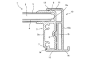
太陽電池モジュール1は図3に示すように、太陽電池素子2の上面がガラスまたは透明樹脂板3で保護され、裏面がアルミニウム板4で保護され、更に周縁部にフレーム5が取付けられている。
As shown in FIG. 3, in the
フレーム5はアルミニウムや樹脂などからなり、中空状の本体部分5aと太陽電池モジュール1の周縁部が差し込まれる溝部5bからなり、本体部分5aは全体の2/3程度の厚みを有する。また、フレーム5の太陽電池モジュール1の厚み方向を基準とした上端部と下端部には、係合部6、7が設けられている。この係合部6、7は例えば爪形状とする。更に、フレーム5の外側面の中間箇所には凹部8が設けられている。
The
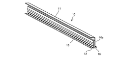
一方、連結部材10はフレーム5と同様にアルミニウムや樹脂などからなり、その形状は太陽電池モジュール1の辺に沿う直線状をなし、その長さは太陽電池モジュール1の連結される辺の長さ以下とされている。連結部材がアルミニウムの場合、押出し成形により製造することができ、その肉厚を1〜2mm程度とすることができる。
On the other hand, the connecting
また、前記連結部材10は、中空状の本体部分10aと上端部及び下端部に設けられるフランジ部11、12を有し、全体としてフレーム5を抱持する形状をなしている。
尚、実施例ではフランジ部11、12がフレーム5を外側から抱持する形状としたが、フレーム5が連結部材10を抱持する形状としてもよい。
The connecting
In the embodiment, the
前記フランジ部11の内側は市にはフレーム5の係合部6と係合する係合部13が形成され、前記フランジ部12の内側端にはフレーム5の係合部7と係合する係合部14が形成されている。係合部7、14については後述するように、この係合箇所を中心として回動させてフレームム5に連結部材10を嵌めつけるため、係合部7は丸まった凹部とし、係合部14は丸まった凸部とするのが好ましい。
An
また、前記連結部材10の本体部分10aには前記フレーム5の外側面に設けた凹部8に係合する凸部15が形成され、連結部材10の下端部には前記フランジ部12とは反対方向に突出するフランジ部16を形成している。このフランジ部16は図5に示すように、架台17などの別部材にボルト18及び押え部材19を介して固定する。
Further, the
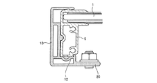
図6は別実施例の断面図であり、この実施例にあっては、フランジ部16の代わりにフランジ部20を内側に突出させ、このフランジ部20を介して架台などに固定するようにしている。
FIG. 6 is a cross-sectional view of another embodiment. In this embodiment, instead of the
以上において、連結部材10をフレーム5に取付けるには、先ず複数の太陽電池モジュール1の辺を揃えて並べ、2つの太陽電池モジュール1のフレーム5に跨るように、連結部材10をフレーム5に嵌め込む。
In the above, in order to attach the connecting
連結部材10をフレーム5に嵌め込むには、先ず、連結部材10の下端部に設けられるフランジ部12に形成した係合部14をフレーム5の係合部7に嵌め込む。これにより連結部材10は係合部7、14を中心として回動可能とされる。そして、連結部材10をフレーム5に向けて回動させることで、連結部材10は2つの太陽電池モジュール1のフレーム5に跨って嵌めつけられ、一体化される。
In order to fit the connecting
またこのとき、フレーム5の凹部8には連結部材10の凸部15が係合するので、風などが太陽電池モジュール1の裏面側に入り込んで、太陽電池モジュール1を外側に持ち上げる力が作用しても、連結部材10からフレーム5が外れることはない。
At this time, since the
上述のように連結部材10を用いて連結した太陽電池モジュール1の設置構造を図7(a)に示す。なお図7(b)は従来の設置構造である。従来の設置構造では、太陽電池モジュール1の1枚の幅ごとに架台17を設け、1枚の太陽電池モジュール1はその両端を架台に固定することによって設置されていた。一方、連結部材10を用いて太陽電池モジュール1を連結した場合、複数の太陽電池モジュール1が連結部材により一体化しているので、太陽電池が固定される架台17の本数を従来に比べて削減できるとともに、ボルト18による固定点を削減することができるため、容易に取りつけを行うことができる。
The installation structure of the
なお、太陽電池モジュール1の支持部材として、上述の形態では架台17を示したが、これに限らず、図8に示すような支持柱80とした設置構造としてもよい。
In addition, as the support member of the
木発明に係る太陽電池モジュールの連結構造は、屋根、壁面、各種形状の架台などに取付ける際に利用することができる。 The connection structure of solar cell modules according to the present invention can be used when attaching to a roof, a wall surface, various shapes of mounts, and the like.
1…太陽電池モジュール、2…太陽電池素子、3…ガラスまたは透明樹脂板、4…アルミニウム板、5…フレーム、5a…中空状の本体部分、5b…溝部、6、7…係合部、8…凹部、10・‥連結部材、10a…本体部分、11、12…フランジ部、13、14…係合部、15…凸部、16…フランジ部、17…架台、18…ボルト、19…押さえ部材、20…フランジ部。
DESCRIPTION OF
Claims (3)
Priority Applications (1)
| Application Number | Priority Date | Filing Date | Title |
|---|---|---|---|
| JP2010198678A JP5480073B2 (en) | 2010-09-06 | 2010-09-06 | Solar cell module connection structure and connection method |
Applications Claiming Priority (1)
| Application Number | Priority Date | Filing Date | Title |
|---|---|---|---|
| JP2010198678A JP5480073B2 (en) | 2010-09-06 | 2010-09-06 | Solar cell module connection structure and connection method |
Publications (3)
| Publication Number | Publication Date |
|---|---|
| JP2012059747A JP2012059747A (en) | 2012-03-22 |
| JP2012059747A5 JP2012059747A5 (en) | 2012-12-27 |
| JP5480073B2 true JP5480073B2 (en) | 2014-04-23 |
Family
ID=46056554
Family Applications (1)
| Application Number | Title | Priority Date | Filing Date |
|---|---|---|---|
| JP2010198678A Expired - Fee Related JP5480073B2 (en) | 2010-09-06 | 2010-09-06 | Solar cell module connection structure and connection method |
Country Status (1)
| Country | Link |
|---|---|
| JP (1) | JP5480073B2 (en) |
Families Citing this family (6)
| Publication number | Priority date | Publication date | Assignee | Title |
|---|---|---|---|---|
| JP5998741B2 (en) * | 2012-08-21 | 2016-09-28 | 三菱電機株式会社 | Solar cell module mounting structure |
| KR102086548B1 (en) | 2012-12-17 | 2020-03-10 | 삼성디스플레이 주식회사 | Pyrene-based compound and organic light emitting diode comprising the same |
| KR101557987B1 (en) | 2014-05-30 | 2015-10-07 | 씨에스에너지(주) | Fixing device of roof type solar cell module |
| WO2016024310A1 (en) * | 2014-08-11 | 2016-02-18 | 株式会社ジャパンエネルギーグループ | Solar power generation panel and method for attaching solar power generation panel unit |
| JP6877929B2 (en) * | 2016-09-15 | 2021-05-26 | 株式会社Nttファシリティーズ | How to install the photovoltaic power generation unit and the solar cell module |
| CA3036341C (en) * | 2016-09-29 | 2020-11-17 | Yanegijutsukenkyujo Co., Ltd. | Fixing structure of solar cell module |
Family Cites Families (3)
| Publication number | Priority date | Publication date | Assignee | Title |
|---|---|---|---|---|
| JP5273909B2 (en) * | 2006-03-29 | 2013-08-28 | 京セラ株式会社 | Solar power plant |
| JP5004910B2 (en) * | 2008-09-08 | 2012-08-22 | 三菱電機株式会社 | Roof type solar cell panel device and cover body |
| JP4365449B2 (en) * | 2009-05-01 | 2009-11-18 | 株式会社屋根技術研究所 | Solar cell module construction method |
-
2010
- 2010-09-06 JP JP2010198678A patent/JP5480073B2/en not_active Expired - Fee Related
Also Published As
| Publication number | Publication date |
|---|---|
| JP2012059747A (en) | 2012-03-22 |
Similar Documents
| Publication | Publication Date | Title |
|---|---|---|
| JP5480073B2 (en) | Solar cell module connection structure and connection method | |
| JP6034427B2 (en) | Solar array | |
| JP2007165499A5 (en) | ||
| JP2004006625A (en) | Solar cell module and solar cell array | |
| JP2010027979A5 (en) | ||
| JP2010027979A (en) | Solar photovoltaic system, and method of manufacturing the same | |
| US20170328602A1 (en) | Fixing metal bracket and solar battery system | |
| WO2012153621A1 (en) | Solar cell system and solar cell module | |
| JP6480675B2 (en) | Solar cell module, building with solar cell, and installation method of solar cell module | |
| JP2015131612A (en) | Solar cell panel for vehicle | |
| KR101421808B1 (en) | Frame for installing solar cell module and installing structure of the solar cell module using the same | |
| JP5744469B2 (en) | Mounting system for photovoltaic modules | |
| JP2007273723A5 (en) | ||
| JP2015227558A (en) | Photovoltaic power generator | |
| JP2009243062A (en) | Mounting device for solar cell module | |
| WO2013108468A1 (en) | Solar cell module | |
| JP3176957U (en) | Support bracket for frame support of solar panels used for folding roofs | |
| JP2013117097A (en) | Car port including solar cell module | |
| BR0306959A (en) | High composite material spring module with affixing connections | |
| JP7173788B2 (en) | ROOF STRUCTURE AND METHOD OF CONSTRUCTING ROOF STRUCTURE | |
| JPWO2017104099A1 (en) | Reinforcing member for solar cell module and solar cell module | |
| WO2015068538A1 (en) | Solar cell system and solar cell module | |
| JP5940043B2 (en) | Solar cell module and solar cell system | |
| KR20150026824A (en) | Photoelectric panel assembly | |
| JP5540045B2 (en) | Mounting structure of solar cell module |
Legal Events
| Date | Code | Title | Description |
|---|---|---|---|
| A521 | Written amendment |
Free format text: JAPANESE INTERMEDIATE CODE: A523 Effective date: 20121109 |
|
| A621 | Written request for application examination |
Free format text: JAPANESE INTERMEDIATE CODE: A621 Effective date: 20121109 |
|
| A977 | Report on retrieval |
Free format text: JAPANESE INTERMEDIATE CODE: A971007 Effective date: 20131007 |
|
| A131 | Notification of reasons for refusal |
Free format text: JAPANESE INTERMEDIATE CODE: A131 Effective date: 20131022 |
|
| A521 | Written amendment |
Free format text: JAPANESE INTERMEDIATE CODE: A523 Effective date: 20131220 |
|
| TRDD | Decision of grant or rejection written | ||
| A01 | Written decision to grant a patent or to grant a registration (utility model) |
Free format text: JAPANESE INTERMEDIATE CODE: A01 Effective date: 20140204 |
|
| A61 | First payment of annual fees (during grant procedure) |
Free format text: JAPANESE INTERMEDIATE CODE: A61 Effective date: 20140213 |
|
| R150 | Certificate of patent or registration of utility model |
Ref document number: 5480073 Country of ref document: JP Free format text: JAPANESE INTERMEDIATE CODE: R150 |
|
| LAPS | Cancellation because of no payment of annual fees |


