JP5478564B2 - Method and apparatus for indicating packing pressurization amount in joint - Google Patents
Method and apparatus for indicating packing pressurization amount in joint Download PDFInfo
- Publication number
- JP5478564B2 JP5478564B2 JP2011152348A JP2011152348A JP5478564B2 JP 5478564 B2 JP5478564 B2 JP 5478564B2 JP 2011152348 A JP2011152348 A JP 2011152348A JP 2011152348 A JP2011152348 A JP 2011152348A JP 5478564 B2 JP5478564 B2 JP 5478564B2
- Authority
- JP
- Japan
- Prior art keywords
- packing
- joint
- ring
- pressurization
- amount
- Prior art date
- Legal status (The legal status is an assumption and is not a legal conclusion. Google has not performed a legal analysis and makes no representation as to the accuracy of the status listed.)
- Active
Links
Images


Landscapes
- Joints With Sleeves (AREA)
- Clamps And Clips (AREA)
- Mutual Connection Of Rods And Tubes (AREA)
- Gasket Seals (AREA)
Description
本発明は、管体の外周に配置した継手リングと管体の先端部を差し込む継手本体及び継手リングと継手本体の間に配置したパッキングによって構成された継手におけるパッキング加圧量の標示方法及び装置に関するものである。 The present invention relates to a joint ring disposed on the outer periphery of a pipe body, a joint main body into which the tip of the pipe body is inserted, and a packing pressure amount indicating method and apparatus in a joint constituted by packing disposed between the joint ring and the joint main body. It is about.
排水用の鋼管などに用いられる継手は、ボルトとナットの締め付けによりパッキングを圧縮して止水する構造となっており、締め付け加圧量(締め付け力)が適切なトルクでなされていなければ、漏水等の事故の引き金となる。この種の継手は管体の外周に配置した継手リングと管体の先端部を差し込む継手本体及び継手リングと継手本体の間に配置したゴム製パッキングを有しており、所期の止水性能を発揮するにはパッキングが適正なトルクで締め付けられて、継手本体、管体及び継手本体との接触面においてそれぞれ適切な加圧力で接触していなければならない。 Fittings used in steel pipes for drainage, etc. have a structure that compresses the packing by tightening bolts and nuts to stop the water. If the tightening pressure (clamping force) is not at an appropriate torque, water leakage will occur. Trigger the accident. This type of joint has a joint ring placed on the outer periphery of the pipe body, a joint body into which the tip of the pipe body is inserted, and a rubber packing placed between the joint ring and the joint body. In order to achieve this, the packing must be tightened with an appropriate torque, and must be in contact with each other at an appropriate pressure on the contact surfaces of the joint body, the pipe body, and the joint body.
継手を組み立てる場合、従来はパッキングを加圧するボルトの締め付けトルクによって管理を行っている。この管理方法を取る場合、パッキングの硬度のばらつき、ボルトの材質、ボルトと締め付け対象物との間の摩擦力であるとか、継手本体、継手リング、パッキングの寸法誤差など多くのパラメーターの影響を受け、かつ、締め付け距離の僅かな変化が加圧量の大きな変化を来たすため、パッキングの加圧力にばらつきを生じており、管体の円周に沿った加圧の均等、適正な管理が困難であった。 In the case of assembling the joint, the management is conventionally performed by the tightening torque of the bolt that pressurizes the packing. This management method is affected by many parameters such as variations in packing hardness, bolt material, frictional force between the bolt and the object to be tightened, joint body, joint ring, and packing dimensional error. In addition, since a slight change in the tightening distance causes a large change in the amount of pressurization, there is a variation in the pressure applied to the packing, making it difficult to evenly and properly manage the pressurization along the circumference of the tube. there were.
さらに、排水用配管は建物の床下や各階の間に多数配管されており、使用される継手数も多数になる。継手1個にパッキング締付け用ボルトは4本〜12本が用いられ、全ての継手の接続は建築現場で施工されるので、おびただしい数のボルト締めが必要であり、適正トルクで締められたか否かを施工後に管理することが困難であった。実際に発生する漏水事故はボルトの締め忘れが原因となる抜管であり、或いは、ボルトの締め過ぎが原因の過大トルクによる経時的破断である。 Furthermore, a large number of drainage pipes are provided under the floor of the building or between each floor, and the number of joints used is also large. Since 4 to 12 packing tightening bolts are used for one joint, and all joints are connected at the construction site, a large number of bolts must be tightened. It was difficult to manage after construction. A water leakage accident that actually occurs is a tube piercing caused by forgetting to tighten the bolt, or a lapse of time due to excessive torque caused by overtightening of the bolt.
先行技術調査により見出されたものに、例えば、特開平9−72325がある。同発明は座金付きナットであり、ナットに相対回転可能に結合され、大径端部の環状の端面である締結面に軸方向に突出している突起を有し、締結時に大径端部が弾性変形して突起が締結面から没入し、隆起が形成されるという構成のものである。また、特開平9−229036はボルトを通すトルク管理金具の外周側に屈折片を形成し、屈折片が変形を完了したときのトルクを以ってトルク管理を行うというものである。これらは、ボルトで変形させてトルクを確認するので、締め付け不足については防止できるが、過剰な締め付けは管理することができない。また、一般に、トルク値での管理の場合、同じトルクで締め付けを行っても締め付け対象やボルトの設置状況や個体差等によって加圧量が変化してしまうという欠点がある。 For example, Japanese Patent Laid-Open No. 9-72325 has been found by prior art search. The present invention is a nut with a washer, which is coupled to the nut so as to be relatively rotatable, and has a projection protruding in an axial direction on a fastening surface which is an annular end surface of the large diameter end portion, and the large diameter end portion is elastic at the time of fastening. The protrusion is deformed to be immersed from the fastening surface, and a bulge is formed. Japanese Patent Laid-Open No. 9-229036 discloses that a refraction piece is formed on the outer peripheral side of a torque management fitting through which a bolt is passed, and torque management is performed using the torque when the refraction piece completes deformation. Since these are deformed with bolts and the torque is confirmed, insufficient tightening can be prevented, but excessive tightening cannot be managed. Further, in general, in the case of management with a torque value, there is a drawback that the amount of pressurization changes depending on the tightening target, the installation status of bolts, individual differences, etc., even when tightening with the same torque.
これに対して本発明者は、パッキング加圧量を直接標示する方法について研究を進めてきた。その結果、後述するように加圧前のパッキングの外周長と、加圧後のパッキングの外周長の差が、パッキング加圧量と直線的比例関係になるという事実を見出した。この知見を利用して、パッキング加圧量を視覚的に標示することが実現できるなら、おびただしい数のボルト締めが必要な場合でも、施工後に適正トルクで締められたか否かを目視により管理することが容易になる。本発明は、この知見の実用化を目指して研究した結果、到達したものである。 On the other hand, the present inventor has been researching a method for directly indicating the packing pressurization amount. As a result, the present inventors have found that the difference between the outer peripheral length of the packing before pressurization and the outer peripheral length of the pack after pressurization is linearly proportional to the packing pressurization amount, as will be described later. If it is possible to use this knowledge to visually indicate the amount of pressure applied to the packing, even if a large number of bolts need to be tightened, it should be visually controlled whether or not it has been tightened with the appropriate torque. Becomes easier. The present invention has been achieved as a result of studies aimed at putting this knowledge into practical use.
本発明はこのような経緯からなされたもので、その課題は、継手をボルト締めにより加圧する場合において加圧力を直接検知し、適切な加圧量を標示することにより、加圧力の不足と過大を目視にて識別できるようにすることである。また、本発明の他の課題は、トルク管理を行う際に介在するパラメーターとしてパッキングの外周長に着目し、以って、パッキングに対する加圧量を正確に反映したトルク管理を可能にすることである。また、本発明の他の課題は、継手を組み立てた後でパッキングの加圧量を視覚的に標示することにより、第三者がトルクの適正管理を一目で行えるようにすることである。 The present invention has been made based on such circumstances, and the problem is that when pressurizing the joint by bolting, the pressurization force is directly detected, and an appropriate pressurization amount is indicated to indicate that the pressurization is insufficient or excessive. Is to be identified visually. Another object of the present invention is to focus on the outer circumferential length of the packing as a parameter that is present when performing torque management, thereby enabling torque management that accurately reflects the amount of pressure applied to the packing. is there. Another object of the present invention is to allow a third party to perform appropriate torque management at a glance by visually indicating the amount of pressure applied to the packing after assembling the joint.
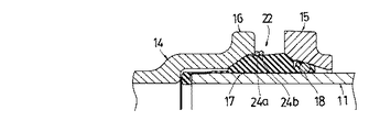
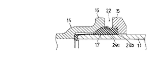
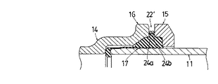
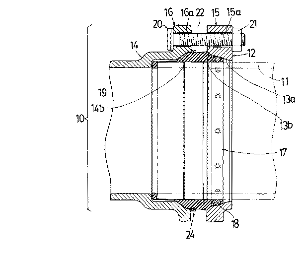
本発明では、管体の外周に配置した継手リングと管体の先端部を差し込む継手本体及び継手リングと継手本体の間に配置したパッキングを有し、上記継手リングと継手本体をボルト締めにより加圧し、少なくとも上記継手リングと継手本体の一方に形成した傾斜面による分力でパッキングを管体の外面に密着させる継手が対象となる。そこで、初めに本発明の基礎となった原理と実験による実証について簡単に説明する。図1は上記の継手リング12と継手本体14及び管体11の間に配置したパッキング17の継手装置において、特に要点となる部分を拡大した模式図であり、継手リング12と継手本体14の双方に傾斜面12a、14bを有している。パッキング17は管体11と面11aで接触し、継手リング12とは面12bの範囲で、継手本体14とは面14b、14cで接触している。継手本体14の面14aは狭隘であるが開放面であり、管体内部の給排水の水圧上昇により漏水経路となる。また、パッキング17の面17aは鋼球なしの場合は図7と図8に示すように管体11に対し垂直で、鋼球ありの場合には継手装置組み立て前はスリット17bが入っているが、組み立て後は鋼球18に押されて壁を構成するのでこの図1と同様と考えて良い。
ボルト締め付け前、即ち、トルクT(Nm) がゼロのときの継手リング12と継手本体14それぞれのフランジ間の間隙22をG(mm)とし、ボルトにトルクT(Nm)を掛けて締め付けたとき、フランジ間の間隙22はΔG(mm)だけ減少して、間隙22′は(G−ΔG)となり、弾性体であるパッキング17には加圧量W(N)が加わり、このパッキング17と接触している継手リング12、継手本体14及び管体11の各面には垂直ベクトルで同じ圧力量のw(N/mm2)が加えられる。なお、図1中の寸法は供試部品の実寸(単位:mm)であるが、便宜上記入したもので本発明を限定的に解釈するために利用してはならない。
間隙22は自由空間であり、パッキング17の圧縮した体積分と比例した体積が膨れ上がり膨らみ23が形成される。膨らみ23の高さ(半径方向の変化量)をΔd/2(mm)とし、パッキング17の外周の増加量をΔL、パッキング高さ(12b)をh(mm)とすればパッキング17の弾性範囲内で、次式(1)が成り立つ。
W =α′・Δd/2 = α′ΔL/2π=αΔL ・・・・・(1)
即ち、パッキング17に対する加圧量Wは、パッキング17の半径方向の膨らみ23の高さΔd/2に比例する。ここに、αは継手構造寸法、パッキング形状及び弾性係数等によって決まる定数である。また、Wにより圧縮されたパッキング17の体積に比例した体積が、フランジ間の間隙22に出っ張るように入り込んだ膨らみ23の体積となるから、式(2)が成り立つ。η(<1)はパッキング物理定数、形状によってきまる定数である。
Δd/2 =η・ΔG・h/(G−ΔG) ・・・・・(2)
以上の式(1)及び(2)より、
パッキング17の外周の変化ΔL(mm)は、
ΔL=2π・Δd/2 =2π・η・ΔG・h/(G−ΔG)・・・(3)
W =α・ΔL/2π = α・η・ΔG ・h/(G−ΔG)・・・(4)
The present invention has a joint ring disposed on the outer periphery of the pipe body, a joint body into which the tip of the pipe body is inserted, and a packing disposed between the joint ring and the joint body, and the joint ring and the joint body are added by bolting. The joint is a target that pressurizes and tightly seals the packing to the outer surface of the tubular body by a component force of an inclined surface formed on at least one of the joint ring and the joint body. First, the principle and the demonstration based on the experiment, which are the basis of the present invention, will be briefly described. FIG. 1 is an enlarged schematic view of a particularly important part in the joint device of the
Before tightening the bolt, that is, when the torque T (Nm) is zero, the
The
W = α ′ · Δd / 2 = α′ΔL / 2π = αΔL (1)
That is, the amount of pressure W applied to the
Δd / 2 = η · ΔG · h / (G−ΔG) (2)
From the above formulas (1) and (2),
The change ΔL (mm) of the outer periphery of the
ΔL = 2π · Δd / 2 = 2π · η · ΔG · h / (G−ΔG) (3)
W = α · ΔL / 2π = α · η · ΔG · h / (G−ΔG) (4)
以上の諸式の再現性や直線性は本発明の基礎となるものであり、実験による実証結果を得ているので、以下に簡単に説明する。
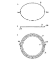
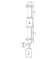
試験継手には、図3に示した構造を有する出願人会社製品の鋼球付き継手「IML100ソケット型」を用い、これを垂直に設置して下端を固定し、上端は使用状況と同じく、管体、パッキングを組み立て、圧力計の加圧部に継手リングを装着して、加圧量W(N)を0から増加させ、それに従って、パッキング外周長ΔL(mm)とフランジ間の間隙(G−ΔG)(mm)を測定したものでその結果は表1に示したとおりである。
表1
ここで外周長ΔLの測定は本発明に基づく装置、すなわち1mm直径のバネ材で作った欠円形のリングをパッキング外周に沿って装着し(図3参照)、端部の変位量を実測した。また、Δd/2は式(3)からΔL/2πの計算値である。なお、「IML−100ソケット型」のその他の諸元は、間隙22:G=14.6mm、パッキングの高さ:h=8mm、定数η=0.4である。
The reproducibility and linearity of the above equations are the basis of the present invention, and experimental verification results have been obtained.
For the test joint, use the steel ball joint “IML100 socket type” manufactured by the applicant company with the structure shown in FIG. 3, which is installed vertically and fixed at the lower end. The body and packing are assembled, and a joint ring is attached to the pressurizing portion of the pressure gauge, and the pressurization amount W (N) is increased from 0, and the gap between the packing outer peripheral length ΔL (mm) and the flange (G -ΔG) (mm) was measured, and the results are as shown in Table 1.
Table 1
Here, the outer peripheral length ΔL was measured by mounting a device based on the present invention, that is, by mounting a round ring made of a spring material having a diameter of 1 mm along the outer periphery of the packing (see FIG. 3), and actually measuring the amount of displacement at the end. Δd / 2 is a calculated value of ΔL / 2π from Equation (3). The other specifications of the “IML-100 socket type” are: gap 22: G = 14.6 mm, packing height: h = 8 mm, and constant η = 0.4.
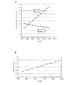
上記実測値及び上記理論値は式(1)〜式(4)をプロットしたのが図2Aに示したグラフであり、パッキング弾性の範囲内で実測値と理論式とは一致し、相関係数0.997である。
W(N)=α・ΔL(mm) ・・・・・・・・・・・・・・(5)
ここにα=643である。
上記の相関係数は、相関係数の算出に一般的に用いられる以下の公式を用いて算出した。
図2Aのグラフは、パッキングの外周長の変化ΔL(mm)がパッキングに掛かる加圧量W(N)に正確に、かつ直線的に比例して変化することを示している。これは長さの変化を「目測で計る」「目視による管理」のにおいて重要な要素である。比較のために、継手本体のフランジと継手リングのフランジ間の間隙(G−ΔG)(mm)と加圧量W(N)との実測値と理論値(η=0.4における(3)、(4)式)をグラフ上に併記したがこれも一致しており、本発明の基礎になる理論の妥当性を示している。試みに、単位加圧量当たりの変化量(即ち加圧感度)を比較してみると
∂ΔL/∂Wと ∂(G−ΔG)/∂Wとの比較
W=12000N近傍において
∂ΔL/∂(G−ΔG)≒ 5.3〜6 倍
即ち、従来のギャップ間の間隔長を測定に利用するとか、或いはボルト、ワッシャー間の変位を利用する加圧測定にくらべ感度が5倍程度高いことを示しており、従って、数倍高い精度を得られることが分かる。
The measured values and the theoretical values are the graphs shown in FIG. 2A in which the formulas (1) to (4) are plotted. The measured values and the theoretical formulas agree with each other within the packing elasticity range, and the correlation coefficient. 0.997.
W (N) = α · ΔL (mm) (5)
Here, α = 643.
The above correlation coefficient was calculated using the following formula generally used for calculating the correlation coefficient.
The graph of FIG. 2A shows that the change ΔL (mm) in the outer circumferential length of the packing changes accurately and linearly in proportion to the pressurization amount W (N) applied to the packing. This is an important factor in the “measurement by length” and “visual management” of the change in length. For comparison, the measured value and the theoretical value ((3) at η = 0.4) of the gap (G−ΔG) (mm) between the flange of the joint body and the flange of the joint ring (mm) and the pressurization amount W (N). (4)) is also shown on the graph, and this also agrees, indicating the validity of the theory underlying the present invention. In comparison, when comparing the amount of change per unit pressure (ie, pressure sensitivity), the comparison between ∂ΔL / ∂W and ∂ (G−ΔG) / ∂W is around W = 12000N.
∂ΔL / ∂ (G-ΔG) ≒ 5.3-6 times That is, the sensitivity is 5 compared with the conventional measurement using the gap length between gaps or the pressure measurement using displacement between bolt and washer. It is shown that the accuracy is several times higher, and therefore several times higher accuracy can be obtained.
<漏水限界圧について>
排水用の配管に用いられる継手の所要機能は言うまでも無く、管体内の規定の水圧に対して漏水しないことである。上述した本発明の基本理論は、漏水限界圧力についても妥当するので、次にこの点を簡単に説明する。パッキングの加圧量W(N)に対し、漏水しない管内最大圧力をW時における漏水限界圧Pmaxとしたとき、表2と図2Bにより漏水のメカニズムと、W(N)と管体内水圧P(N/m2)には次の相関関係が成り立つ。
漏水があった場合、図1では管体内の水が継手本体内の管体11の端部を通過して面14aに達し、パッキング全周に亘り面14aを水圧P(N/m2)で加圧する。一方、加圧力W(N)で加圧されたパッキング17には、全表面に垂直に単位面積当たり加圧力w(N/mm2)の加圧ベクトルが掛かっており、面14aでは水圧Pと加圧力wが相反し、また、面14bではPの分力(約P/√2)と加圧力wが相反している。このことから単位面積当たりの水圧Pと加圧力wとが√2w≦Pで定義されるPmaxがあり、Wに比例するので、本発明の標示は単にパッキング17の加圧力だけでなく、継手の漏水限界圧Pmaxも標示できることが明らかである。
漏水限界圧についても実験による実証結果を得ているので、表2及び図2Bにより結果を簡単に説明する。試験継手には前述した「IML100ソケット型」を用い、実験は前記と同様な装置で管内に注水し、漏水を起こす寸前の管内水圧を測定したもので、下記近似式との相関係数は0.996である。
表2
Pmax(N/mm2)=7×10−5・W(N)
式(5)より、
=7×10⁻⁵・ΔL/α
≒1090・ΔL
即ち、漏水管内弁解水圧Pmaxは、本発明の標示装置を用いて容易に直接標示できることが分かる。
<Leakage limit pressure>
Needless to say, the required function of the joint used in the drainage pipe is to prevent leakage of water against the prescribed water pressure in the pipe. Since the above-described basic theory of the present invention is applicable to the water leakage limit pressure, this point will be briefly described below. When the maximum pressure in the pipe that does not leak with respect to the packing pressurization amount W (N) is the water leakage limit pressure Pmax at W, the water leakage mechanism, W (N), and the pipe water pressure P ( N / m 2 ) has the following correlation.
In the case of water leakage, in FIG. 1, the water in the pipe passes through the end of the
Since experimental verification results have been obtained for the water leakage limit pressure, the results will be briefly described with reference to Table 2 and FIG. 2B. The above-mentioned “IML100 socket type” was used for the test joint, and the experiment was performed by injecting water into the pipe using the same device as described above, and measuring the water pressure in the pipe just before causing water leakage. The correlation coefficient with the following approximate expression was 0 .996.
Table 2
Pmax (N / mm 2 ) = 7 × 10 −5 · W (N)
From equation (5)
= 7 × 10 −5 · ΔL / α
≒ 1090 ・ ΔL
That is, it can be seen that the valve leak pressure Pmax in the leak pipe can be easily and directly indicated by using the indication device of the present invention.
本発明を適用する継手装置は、鋳造品を主体とすることが多いと想定されるが、その場合には、寸法許容精度に余裕が必要であり、また、継手本体、継手リング、パッキング、ボルト等構成部品が多く、組み立て後のフランジ間の間隔などもばらつきがある。金属継手工業会で各部品の標準寸法製造を指定しているので、メーカー間でも互換性があり、他メーカーとの任意の組み合わせにおいても、本発明の標示は有効でなければならない。この確認実験を併せ行なったので以下に説明する。
図19は一対の管体の両端を固定した状態で、パッキングを用いて継手の接合を行い、水を満水状態にした後にポンプで水圧を上昇させ、パッキングの膨らみ量(Δd)毎の漏水時の水圧との関係を調査したものであり、その結果を示すと表3のとおりである。
表3
表3中の大文字M、F、P、B、Cは、それぞれ本体(継手本体)、フランジ(継手リング)、パッキング、ボルト・ナット及び接続管(管体)を示しており、それに付随する小文字のa、b、c・・・は、試験体が別の個体であることを示している。例えば、1で使用した製品の本体Maと、2で使用した製品の本体Maは同一の製品の同一の個体を使用したということであり、1で使用した製品の本体Maと5で使用した製品の本体Mbは同一の製品の別の個体を使用したということである。これらの実験は全て出願人会社製「IML継手の100Aサイズのものを使用した(IML継手とは前記出願人会社製品である排水鋼管用鋼球入り継手「IML−100ソケット型」のことで、100Aサイズとは接続管の内径がおよそ100mmであることを示している)。
さらに、相関係数の算出に一般的に用いられる前々項に示した公式と、以下に示した数値を用いて、本発明におけるパッキングの外周長と漏水限界水圧との相関係数を算出した。
算出した相関係数は以下のとおりであった。
パッキングの膨らみ量と耐水圧の相関係数:0.93
ボルトの締付トルクと耐水圧の相関係数 :0.81
また、100A以外のサイズあるいはIML以外の継手で実験を行った結果を示すと表4に示すとおりである(表4中、JPFMDJ003とは日本金属継手協会の規格品である圧送排水鋼管用可とう継手JPFMDJ003を示す)。
表4
上記の二つの実験結果から得られる相関係数により、パッキングの外周長の増加量を把握することで、パッキングの加圧量を十分に管理できることが理解される。むしろ、得られた相関係数はボルトの締め付けトルクで管理するよりも高い値を示しており、より正確な管理が可能になることを示すものであるといえる。上記の相関関係は、使用部品の組み合わせを変えた場合、他社製品を混用した場合でも当てはまることを示しており、パッキングを圧縮して締め付けを行う際の管理方法として十分な客観性を有するものであると考えることができる。このように、パッキングの外周長をパラメーターとする方法は構成部品のばらつきや、それに起因する間隙のばらつきに左右されないという特徴があり、パッキングの膨らみが適正な接触面加圧力を正確に反映できる唯一の方法であると言って良い。
It is assumed that the joint device to which the present invention is applied is mainly a cast product, but in that case, a margin is required for the dimensional tolerance accuracy, and the joint body, joint ring, packing, bolt There are many equal components and there are variations in the spacing between flanges after assembly. Since the metal fitting industry association has specified the standard size manufacturing of each part, the manufacturers are compatible with each other, and the sign of the present invention must be effective in any combination with other manufacturers. This confirmation experiment was also performed and will be described below.
FIG. 19 shows a state in which both ends of a pair of pipes are fixed, joints are joined using a packing, water is filled, a water pressure is increased by a pump, and water leakage occurs for each swelling amount (Δd) of the packing. The relationship with the water pressure was investigated, and the results are shown in Table 3.
Table 3
Capital letters M, F, P, B, and C in Table 3 indicate the main body (joint body), flange (joint ring), packing, bolt / nut, and connecting pipe (tube body), respectively. A, b, c... Indicate that the specimen is another individual. For example, the main body Ma of the product used in 1 and the main body Ma of the product used in 2 are the same individuals of the same product, and the product used in the main bodies Ma and 5 of the product used in 1 This means that the main body Mb used another individual of the same product. All of these experiments were made by the applicant company using "IML joint of 100A size (IML joint is a joint with steel ball for drainage steel pipe" IML-100 socket type "which is the product of the applicant company, The 100A size indicates that the inner diameter of the connecting pipe is approximately 100 mm).
Furthermore, the correlation coefficient between the outer peripheral length of the packing and the water leakage limit water pressure in the present invention was calculated using the formula shown in the previous paragraph, which is generally used for calculating the correlation coefficient, and the numerical values shown below. .
The calculated correlation coefficient was as follows.
Correlation coefficient between packing swelling and water pressure resistance: 0.93
Correlation coefficient between bolt tightening torque and water pressure resistance: 0.81
The results of experiments conducted with joints other than 100A or joints other than IML are shown in Table 4 (in Table 4, JPFMDJ003 is a flexible product for pressurized drainage steel pipes, a standard product of the Japan Metal Joint Association). The joint JPMDDJ003 is shown).
Table 4
It is understood that the amount of pressurization of the packing can be sufficiently managed by grasping the amount of increase in the outer peripheral length of the packing from the correlation coefficient obtained from the above two experimental results. Rather, the obtained correlation coefficient shows a higher value than that managed by the tightening torque of the bolt, and it can be said that more accurate management is possible. The above correlation shows that this applies even when the combination of parts used is changed or when products from other companies are mixed, and has sufficient objectivity as a management method when compressing and tightening the packing. You can think of it. In this way, the method using the outer circumference of the packing as a parameter has the feature that it does not depend on the variation of the component parts and the gap due to it, and the only way that the swelling of the packing can accurately reflect the appropriate contact surface pressure. It ’s okay to say that.
以上の理論的説明を根拠として、前記の課題を解決するため、本発明は、管体の外周に配置した継手リングと管体の先端部を差し込む継手本体及び継手リングと継手本体の間に配置したパッキングを有し、上記継手リングと継手本体をボルト締めにより加圧し、少なくとも上記継手リングと継手本体の一方に形成した傾斜面による分力でパッキングを管体の外面に密着させる継手において、ボルト締めにより継手リングのフランジと継手本体のフランジが接近し、加圧に伴ってパッキングが圧縮され一部が入り込んで膨らみを生じさせる間隙を両フランジ間に設定し、上記間隙にて膨らんだパッキングの外周長をパラメーターとして、パッキングの加圧量を把握可能にするとともに、上記加圧に伴うパッキングの外周長の増加を視覚的に標示するという手段を講じたものである。 Based on the above theoretical explanation, in order to solve the above-mentioned problems, the present invention provides a joint ring arranged on the outer periphery of the pipe body, a joint main body into which the tip of the pipe body is inserted, and a joint ring and the joint main body. In a joint that has a packing, pressurizes the joint ring and the joint body by bolting, and tightly attaches the packing to the outer surface of the tubular body by a component force by an inclined surface formed on at least one of the joint ring and the joint body. By tightening, the flange of the joint ring and the flange of the joint body approach each other, and the packing is compressed by pressurization and a part of it enters to create a bulge between the two flanges. Using the outer perimeter as a parameter, it is possible to grasp the amount of pressure applied to the packing, and visually indicate the increase in the outer perimeter of the packing due to the above pressurization. It is those that have taken the means of that.
本発明の対象とする継手は、少なくとも上記継手リングと継手本体の一方に形成した傾斜面による分力で、パッキングを管体の外面に密着させる構成を有する継手である。加圧力は外方の継手リング及び継手本体にも及ぶので、その一部が両フランジ間に設定された間隙に入り込んで膨らみを生ずるとも言える。この構成の継手には、管体表面に食い込む鋼球を有するものと鋼球を有しないものとがあるが、本発明はどちらのものにも適用される。本発明の継手におけるパッキング加圧量の標示方法は、加圧に伴うパッキングの外周長の増加を視覚的に標示することを特徴とするものであるが、どのような標示方法を取るかは自由に選択できる事項である。基本的には、パッキングに生じる膨らみを視覚で把握してその適不適を判断することができれば良い。様々な方法があるが、最も望ましい方法としては、継手リングと継手本体の両フランジ間の間隙に、パッキングの外周に接触する欠円形のリングを配置し、上記リングの欠円端部にマーク、着色等目印となるものをそれぞれ設け、上記目印の間隔の変化からパッキングの外周長の増加を視覚的に標示することを挙げることができる。 The joint which is the subject of the present invention is a joint having a configuration in which the packing is brought into close contact with the outer surface of the tubular body by at least a component force generated by the inclined surface formed on one of the joint ring and the joint body. Since the applied pressure also extends to the outer joint ring and the joint body, it can be said that a part of the pressure enters the gap set between the two flanges and causes swelling. Although there exist a thing with a steel ball which bites into the pipe body surface and a thing without a steel ball in the joint of this composition, the present invention is applied to both. The method for indicating the amount of packing pressurization in the joint of the present invention is characterized by visually indicating an increase in the outer peripheral length of the packing accompanying pressurization, but it is free to choose what type of labeling method is used. This is a matter that can be selected. Basically, it is only necessary to visually grasp the bulge generated in the packing and determine its suitability. There are various methods, but the most desirable method is to place a non-circular ring in contact with the outer periphery of the packing in the gap between both flanges of the joint ring and the joint body, It is possible to provide a mark such as a coloring mark and visually indicate an increase in the outer peripheral length of the packing from the change in the interval between the marks.
本発明の方法については、ボルト締めにより継手リングのフランジと継手本体のフランジが接近し、パッキングの加圧に伴って圧縮されたパッキングの一部が両フランジ間の間隙に入り込み得る構成が必要である。通常は、単にフランジとのみ呼ばれることもある継手リングのフランジと、継手本体のフランジとはほぼ同大で、対向して平行に配置され、従って、両フランジ間には、全周においてほぼ一定の間隙が形成される。また、両フランジにはボルト締めのために、管体の中心軸を中心として円周方向に等間隔で数個のボルト通し孔が設けられている。この両フランジ間の等間隔の間隙と、そこに挟まれたパッキングによって、この継手は耐振型可撓性を保つ構造にもなっている。ちなみに耐振型可撓性に関する金属継手工業会規格では、継手に管体が正しく接続された時、接続点から1メートル先の管体端部が上下左右に30ミリメートル振動可能なことが必要なので、その傾きを許容するに十分なフランジ間の間隙、小形継手の場合でも間隙は3mm程度が設けられる。従って、本発明において両フランジ間に設定する間隙にこの3mm程度の間隙を利用することが合理的である。よって、本発明の方法の具体的な適用である、欠円形のリング形状の装置はパッキング外周上に容易に設置可能である。欠円形のリングが弾性材より成ることは望ましいことであるが、非弾性材を用いても本発明の方法を実施できないわけではないので必須の要件ではなくても良い。
The method of the present invention requires a configuration in which the flange of the joint ring and the flange of the joint body come close to each other by bolting, and a part of the packing compressed in accordance with the pressurization of the packing can enter the gap between both flanges. is there. Normally, the flange of the joint ring, sometimes referred to simply as the flange, and the flange of the joint body are almost the same size and are arranged in parallel to each other. A gap is formed. In addition, several bolt through holes are provided in both flanges at equal intervals in the circumferential direction around the central axis of the tube for bolting. The joint is also structured to maintain vibration-proof flexibility by the equally-spaced gap between the flanges and the packing sandwiched therebetween. By the way, in the metal joint industry association standard for vibration resistance type flexibility, when the pipe body is correctly connected to the joint, it is necessary that the end of the
本発明の方法は、上記間隙にて膨らんだパッキングの外周長の増加量を測ることによって、パッキングに加えられた加圧量を直接把握することができるという原理に基づいており、かつまた、加圧量と外周長の増加量が直線的比例関係にあること、さらに加圧量の変化に対する外周長の変化が大きく、換言すれば感度が高いので、簡単な標示機構を用いて、最適な加圧量であることを目視で容易に確認できるという利点を持っている。本発明において外周長を測るという場合の「測る」とは長さを数値として測定することを必ずしも意味せず、パッキングに加えられる加圧量の程度を測ること、上記加圧量の良し悪しの見当を付けること等の意味でもあり、測るための具体的な手段には特定されない。例えば、圧縮量の程度を正確に推し測ったり、良し悪しを判断したりすることができる装置、パッキングの外面にほぼ1.5周又はそれ以上にわたって接触する欠円形のリング形状を有し、かつ、パッキングの外周の変化に伴って弾性変形する弾性ゲージ体で、加圧前に付けたマークを用いてずれを見ること、許容範囲を設定して合否を判定することなどは何れもパッキングに対する加圧量を測る手段としての条件を満たす。 The method of the present invention is based on the principle that the amount of pressurization applied to the packing can be directly grasped by measuring the increase in the outer peripheral length of the packing swollen in the gap. The amount of pressure and the increase in the outer peripheral length are linearly proportional, and the change in the outer peripheral length with respect to the change in the pressurization amount is large, in other words, the sensitivity is high. It has the advantage that it can be easily confirmed visually that it is a pressure amount. In the present invention, “measuring” in the case of measuring the outer peripheral length does not necessarily mean measuring the length as a numerical value, but measuring the degree of pressurization applied to the packing, whether the pressurization is good or bad It is also a meaning such as registering, and is not specified as a specific means for measuring. For example, a device that can accurately estimate the degree of compression or judge whether it is good or bad, has a ring-shaped ring shape that makes contact with the outer surface of the packing for approximately 1.5 laps or more, and An elastic gauge body that is elastically deformed with changes in the outer periphery of the packing. Satisfies conditions as a means of measuring pressure.
また、上記パッキング加圧量の標示方法を実施するための装置も本発明の対象である。この装置は、ボルト締めにより継手リングのフランジと継手本体のフランジを接近させ、パッキングの加圧に伴って圧縮されるパッキングの一部が両フランジ間の間隙に入り込むように、上記両フランジ間に複数個均等に設けた上記のボルトと、上記間隙に入り込むとともに、パッキングの外面に少なくともほぼ1周にわたって接触する欠円形のリング形状を有し、かつ、パッキングの膨らみに伴って弾性変形する弾性ゲージ体と、上記パッキングの膨らみに伴って弾性ゲージ体の周長が増加したときに、弾性ゲージ体の周長の増加を視覚的に標示するため、弾性ゲージ体に設けた標示手段を具備して構成される。欠円形のリングが弾性材より成る必要はないと前述したが、その理由は、弾性材より成るものでなくてもパッキングの外周に接触し、パッキングの膨らみに応じて外周長を増加することができるからである。しかし、弾性変形性の材料を用いれば、パッキング外周への取り付けがより容易であり、常にパッキング外周に接触し密着する傾向にあるためより正確であり表示装置として合理性が高い。 Moreover, the apparatus for implementing the said packing pressurization amount indication method is also the object of the present invention. In this device, the flange of the joint ring and the flange of the joint body are brought close to each other by bolting, and a part of the packing compressed as the packing is pressed enters the gap between the two flanges. A plurality of the above-mentioned bolts provided uniformly, and an elastic gauge that enters the gap and has a ring-shaped ring shape that makes contact with the outer surface of the packing over at least approximately one round and elastically deforms as the packing swells When the circumference of the elastic gauge body increases with the swelling of the body and the packing, the marking means provided on the elastic gauge body is provided to visually indicate an increase in the circumference of the elastic gauge body. Composed. Although it has been described above that the non-circular ring does not need to be made of an elastic material, the reason is that even if it is not made of an elastic material, the ring contacts the outer periphery of the packing and increases the outer peripheral length according to the swelling of the packing. Because it can. However, if an elastically deformable material is used, attachment to the outer periphery of the packing is easier, and since there is a tendency to always come into contact with and close to the outer periphery of the packing, it is more accurate and highly rational as a display device.
弾性ゲージ体として、自由状態において両端部が重なる欠円形のリング形状のものから成り、標示手段は上記両端部に設けられた一対のマークと、フランジに予め設けられた締め付け確認ラインから成るものは望ましい例の一つである。また、両端部がほぼ接する欠円形のリング形状のものから成り、標示手段は上記両端部の一方に、他方へ向けて設けられた軸体と、上記両端部の他方に、軸体と重なる位置に設けた指標とから成り、上記軸体の長さがパッキング加圧量の適正範囲を示している弾性ゲージ体は、他の望ましい例の一つである。さらに、両端部がほぼ接する欠円形のリング形状のものから成り、上記弾性ゲージ体を3個同心円状に、かつ、それぞれの弾性ゲージ体の両端部を周方向へ120度離して配置し、かつ、1個の弾性ゲージ体の両端部の180度反対側で3個の弾性ゲージ体を束ねた構成を有する弾性ゲージ体という構成も望ましい例の一つである。 The elastic gauge body consists of a ring-shaped ring with both ends overlapping in a free state, and the marking means consists of a pair of marks provided at both ends and a tightening confirmation line provided in advance on the flange. This is a desirable example. Further, the both end portions are substantially in the form of a circular ring, and the marking means has a shaft body provided to one end of the both end portions toward the other, and a position overlapping the shaft body on the other end portion. Another desirable example is an elastic gauge body that includes an index provided in the above and the length of the shaft body indicates an appropriate range of the packing pressurization amount. Further, it is composed of a ring-shaped ring shape in which both ends are substantially in contact with each other, three elastic gauge bodies are arranged concentrically, and both ends of each elastic gauge body are arranged 120 degrees apart in the circumferential direction, and A configuration of an elastic gauge body having a configuration in which three elastic gauge bodies are bundled on opposite sides of 180 ° of both ends of one elastic gauge body is also a desirable example.
本発明は以上のように構成されかつ作用するものであるから、継手をボルト締めにより加圧する場合において加圧力を直接検知し、適切な加圧量を標示することにより、加圧力の不足と過大を目視にて識別することができるという効果を奏する。特に、本発明によれば、トルク管理を行う際に介在するパラメーターとしてパッキングの外周長に着目したので、パッキングに対する加圧量のばらつきを減少させることができ、また、外周長は加圧前後におけるパッキングの変化量の大きいパラメーターであるので、標示が容易であり、加圧量の適不適を一目で判別できるので、加圧量を正確に反映したトルク管理が可能になる。また、本発明により、継手を組み立てた後で第三者がパッキングの圧縮量を視覚的に把握して、ボルトの締め忘れや過大なトルクによる経時変化、或いは温度変動などを原因として起きるボルト破断事故を未然に防止できるので、トルクの適正管理が著しく容易に行えるようになる。 また、本発明の標示装置については、安価な部材を材料として、スプリング鋼線や形状記憶樹脂リング、或いはマーキング等の容易な加工工程で実現できるものであり、広い分野に適用できる。 Since the present invention is configured and operates as described above, when pressurizing the joint by bolting, the pressurization force is directly detected, and an appropriate pressurization amount is indicated, whereby the pressurization is insufficient and excessive. The effect of being able to be identified visually. In particular, according to the present invention, attention is paid to the outer circumferential length of the packing as a parameter interposed when performing torque management, so that variations in the amount of pressure applied to the packing can be reduced. Since the parameter has a large amount of change in the packing, the marking is easy, and the suitability of the pressurization amount can be determined at a glance, so that torque management that accurately reflects the pressurization amount is possible. In addition, according to the present invention, after assembling the joint, a third party visually grasps the amount of compression of the packing, and the bolt breaks due to forgetting to tighten the bolt, aging due to excessive torque, or temperature fluctuation Since accidents can be prevented, proper management of torque can be performed extremely easily. Further, the marking device of the present invention can be realized by an easy processing process such as a spring steel wire, a shape memory resin ring, or marking using an inexpensive member as a material, and can be applied to a wide field.
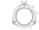
以下図示の実施形態を参照して本発明をより詳細に説明する。図3は本発明に係る継手におけるパッキング加圧量の標示方法の一例を示すもので、排水鋼管用可とう継手に関するものである。図中、10は本発明の対象である継手、11は管体を示しており、本例の場合、例えば排水用の鋼管を使用している。12は継手リングであり、管体11の外周に配置されその内周面には2段階に傾斜面13a、13bが設けられている。14は継手本体であり、管体11の先端部を差し込む接続口14aを両端に有しており、その開口端近くの内周面に傾斜面14bを有している。なお、継手リング12と継手本体14には、例えば鉄系金属の鋳造品が使用される。
Hereinafter, the present invention will be described in more detail with reference to the illustrated embodiments. FIG. 3 shows an example of a method for indicating the packing pressurization amount in the joint according to the present invention, and relates to a flexible joint for a drainage steel pipe. In the figure,
各図において15は継手リングのフランジ、16は継手本体のフランジを示しており、両フランジ15、16には、管体11の中心軸を中心として円周方向に等間隔で数個のボルト通し孔15a、16aが夫々設けられている。17はパッキングを示しており、継手リング12と継手本体14の間に配置されている。パッキング17は弾力性のある素材を用いて、傾斜面13a、13b、14b等に対応した形状に形成されている。図3ないし図に示したパッキング17には、管体11の外面と傾斜面13aとに接触する鋼球18が周方向に多数等間隔で、かつ、回転可能に継手リング側の端部に設けられており、継手本体内方に位置する端部側には、環状の管端防食部19が形成されている。なお、パッキング17にはEPDM製の型成形品が使用されているが、本発明はパッキングの材質に無関係に成立する。
In each figure, 15 is a flange of a joint ring, and 16 is a flange of a joint body. Several bolts are passed through the
継手におけるパッキング加圧量の標示方法
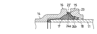
本発明に係るパッキング加圧量の標示方法では、上記の構成を有する継手において、管体11にパッキング17を取り付け、継手リングのフランジ15と継手本体のフランジ16の数個のボルト通し孔15a、16aにボルト20をセットし、かつ、ナット21によって締め付ける。ボルト締めに伴うトルクの増大により、上記両フランジ15、16が接近し、パッキング17が加圧され、それとともに圧縮されるパッキングの一部が両フランジ間の間隙22にて膨らむようになる。加圧力によって、上記間隙(加圧後の状態を符号22′で示す)が狭まり、間隙22′にて膨らんだパッキング17の膨らみ量Δdを測ることによって、パッキング17の加圧量を把握することができる(図6及び図8参照)。
Method for indicating packing pressurization amount in joint In the method for indicating packing pressurization amount according to the present invention, in the joint having the above-described configuration, packing 17 is attached to
標示方法1
間隙22にて膨らんだパッキング17の外周長をパラメーターとして、パッキング17に対する加圧量を正確に把握可能にするためには、上記加圧に伴うパッキング17の外周長の増加を視覚的に標示することができれば良い。視覚的とは、視覚を手段とし、視覚により把握できるというほどの意味である。パッキング17の外周長の増加を視覚的に標示させる手段として、一般的に適用できるものには目印があり、目印の適用方法としては、まず、直接的な方法を取り得る。直接的な方法ではパッキング17の膨らみ23をフランジに付けた目印と比較する方法と、パッキング自体に1又は2以上の標示を付け、パッキングの膨らみにより標示自体又は表示間隔が拡大する方法を取ることが可能である。
標示方法2
目印の間接的な適用方法としては、パッキング17の外周に接触してその外周長の増加に伴い変形する部材を巻き付けるとともに、当該部材に目印を付ける方法がある。この方法は間接的とはいうものの、圧縮後のパッキング17に生じた膨らみ23の大きさを正確に測定することができる手段であり、測定値の差が膨らみ23の量を正確に反映したものとして把握され、変形する部材に付けた目印を目視することで、パッキング17に加えられた加圧量を正確に把握することが可能になる。以下、本発明の方法を適用した装置について、図面を参照して具体的に説明する。
Marking
In order to make it possible to accurately grasp the amount of pressure applied to the packing 17 using the outer peripheral length of the packing 17 swelled in the
Marking
As an indirect application method of the mark, there is a method of winding a member that contacts the outer periphery of the packing 17 and deforms as the outer peripheral length increases, and also marks the member. Although this method is indirect, it is a means by which the size of the
継手におけるパッキング加圧量の標示装置
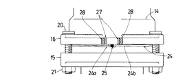
本発明の装置は、前記の継手10において、ボルト締めによるパッキング17の加圧量を標示するために、上記のボルト20と、間隙22にて、パッキング17の外面に接触する欠円形のリング形状を有し、かつ、パッキング17が膨らむことに伴って弾性変形する弾性ゲージ体24と、上記パッキング17の膨らんだ結果リング形状の直径(或いは周長)が増加し、ずれを生じたときにそのずれの量を測るために、弾性ゲージ体24の端部に設けた標示手段を具備している。このパッキング加圧量の標示装置の基本的構成を図示したのが、図3ないし図11に示す例1である。例1のものには、管体表面に食い込む鋼球18を有する図3〜図6のものと、鋼球18を有しない図7及び図8のものとがあるが、パッキング加圧量の標示装置としてはどちらも変わるところがないので、共通の符号を用いて説明する。
Indicating device for packing pressurization amount in joint In the device of the present invention, in order to indicate the pressurizing amount of the packing 17 by bolting in the joint 10, the
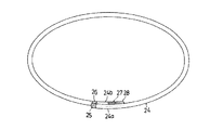
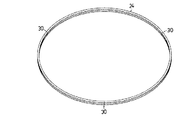
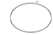
例1のパッキング圧縮量の把握装置は、自由状態において両端部が重なる欠円形のリングからなる弾性ゲージ体24を有している(図9参照)。弾性ゲージ体24は適度の太さを有するバネ鋼あるいは樹脂によって形成されており、リング形状の直径は圧縮前のパッキング17とほぼ同程度で良いが、パッキング17に密着する必要がある。自由状態における弾性ゲージ体24の両端部は図9に2本を並べて示しており、便宜上、一方の端部を24a、他方の端部を24bと区別する。一方の端部24aと他方の端部24bには管理の方法に応じて、公知のあらゆる標示手段が設けられる。即ち、標示手段は管理の方法に応じて変化し得るものである。標示手段は、弾性ゲージ体24の両端部24a、24bだけでなく、フランジ15、16又は弾性ゲージ体24の中間部に設けられることもある。このとき設けられる標示手段の詳細については後段において具体的に説明する。
The packing compression amount grasping device of Example 1 has an
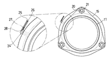
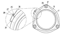
即ち、パッキング17が圧縮前の状態では、動作指標25と初期状態確認指標26が重なった状態にあり(図9)、パッキング17が適正加圧量に圧縮されると動作指標25と適正加圧量確認指標27の位置が重なる。これによってパッキング17が適正加圧量で圧縮されていることを確認できる。さらに、圧縮を続けた場合の過剰加圧によるボルト20の破断を防ぐための警告として、適正加圧量確認指標27に隣接して過剰加圧量確認指標28が設けられている。図9の標示については、弾性ゲージ体24の両端部にマーク(例えば、薄い赤色系の着色)を設け、パッキング17の膨らみに比例して、弾性ゲージ体24が拡径し、両端部とも後方に引っ張られるようにし、かつ、最適の加圧量を示す位置に別のマーク(例えば、白色系の着色)、さらにその先に締め過ぎを示す別のマーク(例えば、濃い赤色系の着色)を設けることができる。継手を2方向から見て、マークが「白」なら合格であり、薄い赤色なら加圧量不足、濃い赤色なら加圧量過剰であることが、目印に加えて着色でも示される。
That is, when the packing 17 is in a state before compression, the
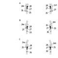
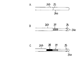
パッキング17の加圧量を把握する標示の例2として、弾性ゲージ体24を約1周半設けた形態を示す(図10及び図11参照)。例2は、弾性ゲージ体24の両端部24a、24bに動作指標25を設け、圧縮前のパッキング17に取付けた弾性ゲージ体24の動作指標25の位置と重なる中間部分の位置に、初期状態確認指標26、適性加圧量確認指標27、過剰加圧量確認指標28を例1と同様に設ける。これにより、加圧量の把握指標を複数個所設けることができ、パッキング17が適正加圧量に圧縮されると、前記例1と同様に動作指標25と適正加圧量確認指標27が重なり、パッキング17が適正加圧量で圧縮されていることを確認できる。圧縮を続けた場合の過剰加圧によるボルト20の破断を防ぐための警告として、過剰加圧量確認指標28を設けられていることは例1と同様である。図11Aは、パッキング17が圧縮前の状態で、動作指標25と初期状態確認指標26が重なった状態であり、パッキング17が適正加圧量に圧縮されると動作指標25と適正加圧量確認指標27が重なる(図11B)。さらに、圧縮を続けた場合には、適正加圧量確認指標27に続けて設けた過剰加圧量確認指標28に動作指標25が重なることにより(図11C)、過剰加圧によるボルト20の破断を防ぐための警告がなされる。これによってパッキング17が適正加圧量で圧縮されているか否かを一目で確認することができる。
As an example 2 of the indication for grasping the amount of pressurization of the packing 17, an embodiment in which the
パッキング17の加圧量を把握する標示の例3として、弾性ゲージ体24の両端部24a、24bに、パッキング17が圧縮前の状態で重なる動作指標25を設けた形態を示す(図12、図13参照)。フランジ15、16には、適正加圧量確認指標27及び過剰加圧量確認指標28があらかじめ設けられている。例3では、パッキング17が適正加圧量に圧縮されると、弾性ゲージ体24の動作指標25と、フランジ15、16の適正加圧量確認指標27の位置が重なり(図13)、これによってパッキング17が適正加圧量で圧縮されていることを目視で確認することができる。さらに、圧縮を続けた場合、適正加圧量確認指標27に隣接した過剰加圧量確認指標28に動作指標25の位置が重なり、過剰加圧によるボルト20の破断を防ぐための警告がなされる。
As an example 3 of the indication for grasping the amount of pressurization of the packing 17, an embodiment is shown in which an
パッキング17の加圧量を把握するための標示の例4として、弾性ゲージ体26の両端部24a、24bに設ける指標を、両端部24a、24bを折り曲げ或いはブラケットを取付けるような構成を加えて、継手リング12のフランジ15及び継手本体14のフランジ16の隙間22の外側に設けた形態を示す(図14、図15参照)。これによって指標はより見易くなる。図14は、パッキング17が圧縮前の状態であり、動作指標25と初期状態確認指標26の位置が重なっている。パッキング17が適正加圧量に圧縮されると、動作指標25と適正加圧量確認指標27の位置が重なり(図14)、これによってパッキング17が適正加圧量で圧縮されていることを確認する。さらに、圧縮を続けた場合、前記と同様に適正加圧量確認指標27に隣接した過剰加圧量確認指標28と動作指標25の位置が重なり、過剰加圧によるボルト20の破断を防ぐための警告がなされる。
As an example 4 of the label for grasping the amount of pressurization of the packing 17, an index provided on both ends 24 a and 24 b of the
パッキング17の加圧量を把握するための標示の例5として、同一半径を有し独立したリング状の弾性ゲージ体24を複数個重ね、かつ、標示指標部30を円周方向へ均等に振り分けることで、多方向から確認できるようにした形態を示す(図16〜図18参照)。例5に示した複数個の独立した弾性ゲージ体24は、円周を三等分した位置に標示指標部30を3箇所ずつ合計9箇所備えており、標示指標部30の向きを固定するために、複数個から成る弾性ゲージ体24を一部で固定している。個々のリング状の弾性ゲージ体24の端部は、三等分割した一方の端部24aを一方の端部24bの中に挿入し出入り可能な構成とすることができる(図18)。これにより複数個の弾性ゲージ体24を密接させ、間隙22に挿入することができる。例5の場合、パッキング17が圧縮前には標示指標部30は閉じており(図18A)、適正加圧量に圧縮されると、例えば青色の適正加圧量確認指標27が現れ(図18B)、これによってパッキング17が適正加圧量で圧縮されていることを確認する。さらに、圧縮を続けると、適正加圧量確認指標27に隣接した例えば赤色の過剰加圧量確認指標28が現れるので、過剰加圧によるボルト20の破断を防ぐための警告がなされる(図18C)。
As an example 5 of the indication for grasping the pressurization amount of the packing 17, a plurality of independent ring-shaped
このように、本発明は、加圧前のパッキングの外周長と、加圧後のパッキングの外周長の差が、パッキング加圧量と直線的比例関係になるという知見を継手におけるパッキング加圧量の標示方法について実用化したものであり、従来の方法から全く示唆されない方法によって、パッキングの最適な加圧量を把握し、かつ、視覚的に標示することを可能にした意義を有する。また、本発明の装置により、パッキング加圧量のばらつきの原因を減少させる具体的な手段が実現され、その結果、当初の目的であるパッキングに対する加圧力の直接検知、最適な加圧量の標示により、加圧力の不足と過大を目視にて識別可能とすることに加えて、パッキングの漏水限界管内圧力の標示にも用いられるなど、広い用途に適用できる余地のあるものである。 As described above, the present invention is based on the knowledge that the difference between the outer circumferential length of the packing before pressing and the outer circumferential length of the packing after pressing is linearly proportional to the packing pressing amount. This method has been put to practical use, and has the significance that it is possible to grasp the optimum amount of pressurization of the packing and visually display it by a method not suggested by the conventional method. In addition, the device of the present invention realizes a specific means for reducing the cause of the variation in the packing pressurization amount. As a result, the direct detection of the pressurizing force on the packing, which is the original purpose, and the indication of the optimum pressurization amount are realized. Thus, in addition to making it possible to visually identify the shortage and excess of the applied pressure, there is room for application to a wide range of applications, such as being used for marking the packing leakage limit pipe pressure.
10 継手
11 管体
12 継手リング
12a、13a、13b、14b 傾斜面
14 継手本体
15、16 フランジ
17 パッキング
18 鋼球
19 管端防食部
20 ボルト
21 ナット
22、22′ 間隙
23 膨らみ
24 弾性ゲージ体
24a、24b 一対のマーク
26 初期状態確認指標
27 適正加圧量確認指標
28 過剰加圧量確認指標
30 標示指標部
DESCRIPTION OF
Claims (6)
ボルト締めにより継手リングのフランジと継手本体のフランジが接近し、加圧に伴ってパッキングが圧縮され一部が入り込んで膨らみを生じさせる間隙を両フランジ間に設定し、上記間隙にて膨らんだパッキングの外周長をパラメーターとして、パッキングの加圧量を把握可能にするとともに、
上記加圧に伴うパッキングの外周長の増加を視覚的に標示することを特徴とする継手におけるパッキング加圧量の標示方法。 A joint ring disposed on the outer periphery of the pipe body, a joint body into which the tip of the pipe body is inserted, and a packing disposed between the joint ring and the joint body, and pressurizing the joint ring and the joint body by bolting, at least the above-mentioned In the joint that tightly attaches the packing to the outer surface of the tubular body by the component force of the inclined surface formed on one of the joint ring and the joint body,
By tightening the bolt, the flange of the joint ring and the flange of the joint body come close, the packing is compressed with pressure and part of it enters to create a bulge between the two flanges. As a parameter, the amount of pressurization of the packing can be grasped,
A method for indicating a packing pressurization amount in a joint, wherein the increase in the outer peripheral length of the packing accompanying the pressurization is visually indicated.
ボルト締めにより継手リングのフランジと継手本体のフランジを接近させ、パッキングの加圧に伴って圧縮されるパッキングの一部が両フランジ間の間隙に入り込むように、上記両フランジ間に複数個均等に設けた上記のボルトと、
上記間隙に入り込むとともに、パッキングの外面に少なくともほぼ1周にわたって接触する欠円形のリング形状を有し、かつ、パッキングの膨らみに伴って弾性変形する弾性ゲージ体と、
上記パッキングの膨らみに伴って弾性ゲージ体の周長が増加したときに、弾性ゲージ体の周長の増加を視覚的に標示するため、弾性ゲージ体に設けた標示手段と
を具備して構成された継手におけるパッキング加圧量の標示装置。 A joint ring disposed on the outer periphery of the pipe body, a joint body into which the tip of the pipe body is inserted, and a packing disposed between the joint ring and the joint body, and pressurizing the joint ring and the joint body by bolting, at least the above-mentioned An apparatus for carrying out a method for indicating a packing pressurization amount in a joint in which a packing is brought into close contact with an outer surface of a tubular body by a component force by an inclined surface formed on one of a joint ring and a joint body,
By bolting, the flange of the joint ring and the flange of the joint body are brought close to each other so that a part of the packing compressed as the packing is pressed enters the gap between the flanges. The above bolts provided,
An elastic gauge body that enters the gap and has a ring-shaped ring shape that is in contact with the outer surface of the packing for at least one round, and elastically deforms as the packing swells;
In order to visually indicate an increase in the circumference of the elastic gauge body when the circumference of the elastic gauge body increases as the packing bulges, it is provided with marking means provided on the elastic gauge body. A device for indicating the amount of packing pressurization in a joint.
標示手段は上記両端部の一方に、他方へ向けて設けられた軸体と、上記両端部の他方に、軸体と重なる位置に設けた指標とから成り、
上記軸体の長さがパッキング加圧量の適正範囲を示している
請求項3記載の継手におけるパッキング加圧量の標示装置。 The elastic gauge body is composed of a ring-shaped ring with substantially circular ends that are substantially in contact with both ends.
The marking means comprises a shaft provided on one side of the both ends toward the other, and an index provided on the other end of the both ends at a position overlapping the shaft.
The marking device for packing pressurization amount in the joint according to claim 3, wherein the length of the shaft body indicates an appropriate range of packing pressurization amount.
Priority Applications (1)
| Application Number | Priority Date | Filing Date | Title |
|---|---|---|---|
| JP2011152348A JP5478564B2 (en) | 2011-07-08 | 2011-07-08 | Method and apparatus for indicating packing pressurization amount in joint |
Applications Claiming Priority (1)
| Application Number | Priority Date | Filing Date | Title |
|---|---|---|---|
| JP2011152348A JP5478564B2 (en) | 2011-07-08 | 2011-07-08 | Method and apparatus for indicating packing pressurization amount in joint |
Publications (2)
| Publication Number | Publication Date |
|---|---|
| JP2013019445A JP2013019445A (en) | 2013-01-31 |
| JP5478564B2 true JP5478564B2 (en) | 2014-04-23 |
Family
ID=47691084
Family Applications (1)
| Application Number | Title | Priority Date | Filing Date |
|---|---|---|---|
| JP2011152348A Active JP5478564B2 (en) | 2011-07-08 | 2011-07-08 | Method and apparatus for indicating packing pressurization amount in joint |
Country Status (1)
| Country | Link |
|---|---|
| JP (1) | JP5478564B2 (en) |
Families Citing this family (3)
| Publication number | Priority date | Publication date | Assignee | Title |
|---|---|---|---|---|
| JP5994744B2 (en) * | 2013-07-18 | 2016-09-21 | ダイキン工業株式会社 | Adjusting method of shaft seal device |
| CN110469729A (en) * | 2019-08-26 | 2019-11-19 | 广东国鸿氢能科技有限公司 | A new ferrule type pipe joint |
| JP7570636B2 (en) * | 2021-05-11 | 2024-10-22 | 鹿島建設株式会社 | Drainage structure for deck slab |
-
2011
- 2011-07-08 JP JP2011152348A patent/JP5478564B2/en active Active
Also Published As
| Publication number | Publication date |
|---|---|
| JP2013019445A (en) | 2013-01-31 |
Similar Documents
| Publication | Publication Date | Title |
|---|---|---|
| CN108138997B (en) | Pipe fitting with sensor | |
| US8024979B2 (en) | Indicating fastener loading | |
| US10006843B2 (en) | Method for predicting remaining life of hose and method for diagnosing deterioration level of hose | |
| US11566956B2 (en) | Pressure sensor for a pipe | |
| EP3673229B1 (en) | Connector assembly evaluation tool and method | |
| JP5478564B2 (en) | Method and apparatus for indicating packing pressurization amount in joint | |
| US20140318260A1 (en) | Pressure indication device of inflation machine with safety pressure relief | |
| JP2014062876A (en) | Hose degradation diagnostic method and hose degradation diagnostic device | |
| CN107402120B (en) | Pipeline clamping device and quality detection method of sealing clamp | |
| CN109029962A (en) | Determine the pilot system of fastening arrangement and method for construction | |
| US5717143A (en) | Apparatus for illustrating bolt preloads | |
| US11536618B2 (en) | External tie-rod load indicator | |
| US20170120429A1 (en) | Precision connections and methods of forming same | |
| JP2013040647A (en) | Gasket interference measuring method of flange | |
| CN102680150A (en) | Nonlinear chirped fiber grating two-dimensional distributed strain sensing pipeline monitor device | |
| CN118464615A (en) | A loading device for studying stress corrosion of epoxy steel bars | |
| KR200487255Y1 (en) | Apparatus for testing and evaluating pipe joint | |
| CN109297458A (en) | Oil and gas pipeline stress and strain monitoring device | |
| Cloostermans et al. | Fiber-Optic Sensing for Seating Stress Quantification in Semi-Metallic Gaskets | |
| US7437936B1 (en) | Window for measuring device | |
| KR101912879B1 (en) | High Density Polyethylene Pipe Damage and Deformation Detection System | |
| JP5667037B2 (en) | Pipeline leak tester | |
| TWI592630B (en) | Displacement sensing structure and sensing method | |
| CN109752108B (en) | A replaceable thermocouple with long service life | |
| JP2007239763A (en) | Flange tightening state inspection method and flange used therefor |
Legal Events
| Date | Code | Title | Description |
|---|---|---|---|
| A621 | Written request for application examination |
Free format text: JAPANESE INTERMEDIATE CODE: A621 Effective date: 20130329 |
|
| TRDD | Decision of grant or rejection written | ||
| A977 | Report on retrieval |
Free format text: JAPANESE INTERMEDIATE CODE: A971007 Effective date: 20140115 |
|
| A01 | Written decision to grant a patent or to grant a registration (utility model) |
Free format text: JAPANESE INTERMEDIATE CODE: A01 Effective date: 20140121 |
|
| A61 | First payment of annual fees (during grant procedure) |
Free format text: JAPANESE INTERMEDIATE CODE: A61 Effective date: 20140210 |
|
| R150 | Certificate of patent or registration of utility model |
Ref document number: 5478564 Country of ref document: JP Free format text: JAPANESE INTERMEDIATE CODE: R150 |
|
| R250 | Receipt of annual fees |
Free format text: JAPANESE INTERMEDIATE CODE: R250 |
|
| R250 | Receipt of annual fees |
Free format text: JAPANESE INTERMEDIATE CODE: R250 |
|
| R250 | Receipt of annual fees |
Free format text: JAPANESE INTERMEDIATE CODE: R250 |
|
| R250 | Receipt of annual fees |
Free format text: JAPANESE INTERMEDIATE CODE: R250 |
|
| R250 | Receipt of annual fees |
Free format text: JAPANESE INTERMEDIATE CODE: R250 |
|
| R250 | Receipt of annual fees |
Free format text: JAPANESE INTERMEDIATE CODE: R250 |
|
| R250 | Receipt of annual fees |
Free format text: JAPANESE INTERMEDIATE CODE: R250 |
|
| R250 | Receipt of annual fees |
Free format text: JAPANESE INTERMEDIATE CODE: R250 |
|
| R250 | Receipt of annual fees |
Free format text: JAPANESE INTERMEDIATE CODE: R250 |
|
| R250 | Receipt of annual fees |
Free format text: JAPANESE INTERMEDIATE CODE: R250 |