JP5476848B2 - Photovoltaic power generation amount prediction method, actual load prediction method, and distribution system control system - Google Patents
Photovoltaic power generation amount prediction method, actual load prediction method, and distribution system control system Download PDFInfo
- Publication number
- JP5476848B2 JP5476848B2 JP2009185543A JP2009185543A JP5476848B2 JP 5476848 B2 JP5476848 B2 JP 5476848B2 JP 2009185543 A JP2009185543 A JP 2009185543A JP 2009185543 A JP2009185543 A JP 2009185543A JP 5476848 B2 JP5476848 B2 JP 5476848B2
- Authority
- JP
- Japan
- Prior art keywords
- distribution system
- power generation
- power
- generator
- current
- Prior art date
- Legal status (The legal status is an assumption and is not a legal conclusion. Google has not performed a legal analysis and makes no representation as to the accuracy of the status listed.)
- Active
Links
Images
Classifications
-
- F—MECHANICAL ENGINEERING; LIGHTING; HEATING; WEAPONS; BLASTING
- F24—HEATING; RANGES; VENTILATING
- F24S—SOLAR HEAT COLLECTORS; SOLAR HEAT SYSTEMS
- F24S2201/00—Prediction; Simulation
-
- Y—GENERAL TAGGING OF NEW TECHNOLOGICAL DEVELOPMENTS; GENERAL TAGGING OF CROSS-SECTIONAL TECHNOLOGIES SPANNING OVER SEVERAL SECTIONS OF THE IPC; TECHNICAL SUBJECTS COVERED BY FORMER USPC CROSS-REFERENCE ART COLLECTIONS [XRACs] AND DIGESTS
- Y02—TECHNOLOGIES OR APPLICATIONS FOR MITIGATION OR ADAPTATION AGAINST CLIMATE CHANGE
- Y02E—REDUCTION OF GREENHOUSE GAS [GHG] EMISSIONS, RELATED TO ENERGY GENERATION, TRANSMISSION OR DISTRIBUTION
- Y02E10/00—Energy generation through renewable energy sources
- Y02E10/50—Photovoltaic [PV] energy
Description
本発明は太陽光発電機が連系されている配電系統における太陽光発電量予測方法および実負荷予測方法、並びにこれらの方法を適用して配電系統の運用を行う配電系統制御システムに関するものである。 The present invention relates to a photovoltaic power generation amount prediction method and an actual load prediction method in a distribution system in which solar power generators are connected, and a distribution system control system that operates the distribution system by applying these methods. .
従来から、無尽蔵な太陽エネルギーを電気エネルギーに変換して発電を行う太陽光発電機の導入が促進されている。かかる太陽光発電機の太陽光発電によれば、エネルギー源として石油等の天然資源に依存する割合を低減でき、地球環境の保全につながるとして期待されている。 Conventionally, introduction of solar power generators that generate electric power by converting inexhaustible solar energy into electric energy has been promoted. According to the solar power generation of such a solar power generator, it is expected that the ratio depending on natural resources such as oil as an energy source can be reduced, leading to conservation of the global environment.
近年、太陽光発電機の導入価格の低下、環境保全意識の高まり、および石油価格の変動による代替エネルギーへの転換需要により、一般家庭等にも太陽光発電機が普及しつつある。特に、新規に開発された住宅地などでは、地域全体に計画的に太陽光発電機を導入し、大規模な太陽光発電が行われるケースも出現し始めている。 In recent years, solar power generators are becoming popular in ordinary homes due to a decrease in the introduction price of solar power generators, an increase in environmental conservation awareness, and demand for conversion to alternative energy due to fluctuations in oil prices. In particular, in newly developed residential areas and the like, there are cases where large-scale solar power generation is performed by introducing solar power generators systematically throughout the region.
通例、一般家庭等に取り付けられた太陽光発電機は、電気事業者の送電線に連系されている。そして、太陽光発電機の発電量の余剰分を、連系された配電系統に折り返し、所定の電気事業者に売却している。なお、一般的には発電した電気量を計測する発電メータ(いわゆる売電メータ)を配置することにより売却電気量を把握している。 Usually, a solar power generator attached to a general household is linked to a power transmission line of an electric power company. And the surplus of the power generation amount of the solar power generator is turned back to the interconnected distribution system and sold to a predetermined electric power company. In general, the amount of electricity sold is grasped by arranging a power generation meter (so-called power sale meter) that measures the amount of electricity generated.
ところで、太陽光発電機が連系した区間において配電系統に事故が発生して停電したとき、それに伴い太陽光発電機の発電も停止するように設定されている。これは、太陽光発電機によって発電された電力が配電系統に折り返され、停電の復旧作業を行っている作業員が感電してしまうおそれ等をなくすためである。 By the way, when a power failure occurs due to an accident in the distribution system in a section where the solar power generators are connected, the power generation of the solar power generator is also stopped accordingly. This is to eliminate the possibility that the electric power generated by the solar power generator is turned back to the power distribution system, and the worker who is performing the power recovery work may receive an electric shock.
しかし、停止された太陽光発電機は、停電が復旧してもすぐに発電を再開できるわけではない。そのため、停電が復旧した当初は、短時間ではあるが通常時は太陽光発電機の発電によってまかなっている分の電力もあわせて、地域全体の負荷(実負荷)を電気事業者(変電所)から配電系統に送出された電力で賄わなければならない。 However, a stopped solar generator cannot resume power generation immediately after a power failure. Therefore, at the beginning of the restoration of the power outage, the load of the entire region (actual load), including the amount of power covered by the power generation of the solar power generator in normal time, is also reduced to the electric utility (substation). Must be covered by the power sent to the power distribution system.
このため、停電から復旧した瞬間に過負荷に陥り、二次的な停電事故に連鎖するおそれがある。過負荷を防止するためには、想定される最大の電力を供給できるように設備を構築する必要がある。 For this reason, there is a risk of being overloaded at the moment of recovery from a power outage and chained to a secondary power outage accident. In order to prevent overload, it is necessary to construct equipment so that the maximum possible power can be supplied.
しかし、通常、電気事業者(変電所)からは配電系統に送り出す送出電力しか把握することができない。すなわち、実負荷の一部が太陽光発電機の発電によってまかなわれているから、実負荷全体を把握することができない。当然、太陽光発電機を連系した一般家庭等に発電量を計測する計測器を取り付け、検針に赴けば発電量を調べることができるが、労力等の点から鑑みるととても現実的ではない。そこで、従来、電気事業者は、計測により分かっている電力量に事前に申請された太陽光発電機の定格発電容量を加え、または各戸の契約電力とかかる定格発電容量を積算して最大の電力を算出していた。そして、この最大の電力がまかなえるように配電設備を整備し、配電線負荷管理(配電系統の運用)を行っていた。 However, the electric power company (substation) can usually grasp only the transmitted power sent to the distribution system. That is, since part of the actual load is covered by the power generation of the solar power generator, the entire actual load cannot be grasped. Of course, it is possible to investigate the amount of power generation by installing a measuring device that measures the amount of power generation in ordinary homes connected to solar power generators, and looking at the meter reading, but it is not very realistic in terms of labor etc. . Therefore, conventionally, the electric power company adds the rated power generation capacity of the solar power generator that has been applied for in advance to the amount of power known from the measurement, or integrates the contract power of each house and the rated power generation capacity to maximize the power Was calculated. Then, distribution facilities were prepared so that this maximum power could be covered, and distribution line load management (operation of the distribution system) was performed.
ところが、上記の運用とすると、太陽光発電機の配電系統への連系が増えるほどにその発電量を包含し得るほどの大容量の配電設備を備える必要がある。それにもかかわらず、この配電設備の容量が必要となるのは停電から復旧するときや、電力品質の一時的な低下による太陽光発電機の一斉脱落時くらいであって通常時は余剰分となってしまうため、設備投資の効率が極めて悪い。さらに、実際に太陽光発電機が発電するのは定格容量の7割程度であるので、総じて相当の無駄を生じていた。 However, if it is said operation | use, it is necessary to provide the large-capacity power distribution equipment which can include the electric power generation amount, so that the connection to the distribution system of a solar power generator increases. Nevertheless, the capacity of this power distribution facility is necessary when recovering from a power outage or when solar power generators are all dropped due to a temporary decline in power quality. Therefore, the efficiency of capital investment is extremely poor. Furthermore, since the solar power generator actually generates about 70% of the rated capacity, a considerable waste was generally generated.
今後、太陽光発電機の配電系統への連系がさらに増加した場合、上記の問題はさらに顕著となる。そこで、実負荷を的確に把握し、過負荷による停電事故を確実に防止すると同時に、余剰な設備投資を抑える必要がある。 In the future, when the interconnection of solar power generators to the distribution system further increases, the above problem becomes more prominent. Therefore, it is necessary to accurately grasp the actual load, reliably prevent power outage accidents due to overload, and at the same time suppress excessive capital investment.
実負荷を把握するためには、配電系統ごとの太陽光発電機の発電量を予測することが考えられる。特許文献1には、太陽光発電機の発電量の予測に関する技術が開示されている。特許文献1の技術によれば、設置地点、容量、直並列枚数、太陽電池の方位角・傾斜角、大気透過率、地域別日最低気温等を勘案することにより、太陽光発電量を天候別に高精度で予測できるとしている。 In order to grasp the actual load, it is conceivable to predict the power generation amount of the solar power generator for each distribution system. Patent Document 1 discloses a technique related to prediction of the amount of power generated by a solar power generator. According to the technology of Patent Document 1, the amount of photovoltaic power generation is classified according to the weather by taking into account the installation point, capacity, the number of series-parallel, the azimuth / inclination angle of solar cells, the atmospheric transmittance, the daily minimum temperature by region, etc. It can be predicted with high accuracy.
また、特許文献2には、三相交流発電機の発電量を予測する技術が開示されている。特許文献2の技術によれば、発電機停止時の正相電流および逆相電流を計算してこれらの関係を表す複素数での1次回帰式を作成し、発電機運転時の逆相電流の実測値を1次回帰式に代入して発電機停止中の正相電流を推定することにより、発電機が運転中の正相電流とこの推定した正相電流の差分から発電機の出力を容易に予測できるとしている。 Patent Document 2 discloses a technique for predicting the power generation amount of a three-phase AC generator. According to the technique of Patent Document 2, a normal-phase current and a reverse-phase current when the generator is stopped are calculated, and a linear regression equation with a complex number representing these relationships is created. By substituting the measured value into the linear regression equation and estimating the positive phase current when the generator is stopped, the generator output can be easily calculated from the difference between the positive phase current when the generator is operating and the estimated positive phase current. It can be predicted.
しかしながら、特許文献1の技術では、日射量に代表される数多くのパラメータを必要とするため、それらのパラメータを取得する計測機器を配置しなければならない。加えて、太陽光発電量を算出する複雑な計算に伴う業務量も多いため、適用には難を有する。 However, since the technique of Patent Document 1 requires a large number of parameters typified by the amount of solar radiation, a measuring device that acquires these parameters must be arranged. In addition, since the amount of work involved in the complicated calculation for calculating the amount of photovoltaic power generation is large, it is difficult to apply.
その上、特許文献1は、個々の太陽光発電機の発電量を予測対象としていて、配電系統における(配電系統ごとの)太陽光発電機の発電量を予測するものではない。特許文献1では太陽光発電量を天候別に予測できるとしているが、配電系統を対象とする場合、その地域の中でも日が差す地点と曇がかかる地点とがあることは誰にでも容易に想定できることであって、個々の太陽光発電機ごとにパラメータを計測して発電量を算出しなければ充分な精度を確保し得ない。そのため、配電系統ごとに天候別に日射量から太陽光発電量を算出することは事実上不可能である。 In addition, Patent Literature 1 uses the power generation amount of each solar power generator as a prediction target, and does not predict the power generation amount of the solar power generator (for each power distribution system) in the power distribution system. Patent Document 1 says that the amount of photovoltaic power generation can be predicted according to the weather, but when the distribution system is targeted, anyone can easily assume that there are spots where the sun falls and where it will be overcast in that area. However, sufficient accuracy cannot be ensured unless the parameters are measured for each individual solar power generator to calculate the amount of power generation. Therefore, it is virtually impossible to calculate the amount of photovoltaic power generation from the amount of solar radiation according to the weather for each distribution system.
一般的に、日射量から太陽光発電機の発電量を予測可能なのは晴天時における発電量のみである。よって、雨天、曇天時における太陽光発電機の発電量は予測することができず、それらの天候時においても晴天時における太陽光発電量を見積もって運用せざるを得ない。すなわち、晴天時における太陽光発電機の発電量と雨天、曇天時における太陽光発電機の発電量(非太陽光発電時)の差分を配電系統に上乗せして運用することとなる。そのため、無駄を生じるのは当然のこと、停電区間が発生した場合にその供給支障電力を正確に把握できないため、変電所からこの停電区間に逆送電を行えるかどうかの可否判定を誤らせるおそれもある。 In general, the amount of power generated by a solar power generator can be predicted from the amount of solar radiation only for the amount of power generated in fine weather. Therefore, it is impossible to predict the power generation amount of the solar power generator when it is raining or cloudy, and it is necessary to estimate the solar power generation amount when the weather is fine and to operate it. In other words, the difference between the power generation amount of the solar power generator in fine weather and the power generation amount of the solar power generator in the rainy and cloudy weather (non-solar power generation) is added to the distribution system for operation. Therefore, it is natural that wastefulness occurs, and when a power outage section occurs, it is not possible to accurately grasp the power that hinders its supply, so there is a risk of misjudging whether or not reverse transmission can be performed from the substation to this power outage section. .
また、特許文献2の技術にあっては、三相交流発電機の発電量を区間開閉器によって計測されたパラメータから、容易に予測できるとしている。しかし、これはあくまで三相交流発電機のみに適用できる技術であって、単相変圧器を介して接続された太陽光発電機の発電量を予測(単相交流発電機)するのには適用できない。三相交流発電機では配電系統における三相交流の不平衡率に影響を与えないものとみなすことができるが、配電系統に単相変圧器(単相交流発電機)を連系した場合、その接続形態(接続相と定格発電容量)に基づき三相交流の不平衡率を変動させるためである。 Moreover, in the technique of patent document 2, it is supposed that the electric power generation amount of a three-phase alternating current generator can be easily estimated from the parameter measured by the section switch. However, this is a technology that can only be applied to a three-phase AC generator, and is applicable to predicting the amount of power generated by a solar generator connected via a single-phase transformer (single-phase AC generator). Can not. It can be considered that the three-phase AC generator does not affect the unbalance rate of the three-phase AC in the distribution system, but when a single-phase transformer (single-phase AC generator) is connected to the distribution system, This is to vary the unbalance rate of the three-phase AC based on the connection form (connection phase and rated power generation capacity).
本発明は、このような課題に鑑みてなされたものであり、容易に入手可能な最低限のデータから配電系統ごとの太陽光発電量を天候に依存せずに精度良く予測できる太陽光発電量予測方法および実負荷予測方法、並びにこれらの方法を適用して配電系統の運用を行う配電系統制御システムを提供することを目的とする。 The present invention has been made in view of such problems, and the amount of photovoltaic power generation that can accurately predict the amount of photovoltaic power generation for each distribution system from the minimum data that can be easily obtained without depending on the weather. It is an object of the present invention to provide a prediction method, an actual load prediction method, and a distribution system control system that operates the distribution system by applying these methods.
上記課題を解決するために本発明にかかる太陽光発電量予測方法の代表的な構成は、配電系統における太陽光発電量予測方法であって、配電系統に連系した太陽光発電機の発電を要因とする三相交流の不平衡率をこの太陽光発電機の接続形態より算出するステップと、配電系統に連系した太陽光発電機の発電がないときの負荷を要因とする三相交流の正相電流および逆相電流の近似関数を導出するステップと、配電系統の電流を計測して、配電系統に連系した太陽光発電機の発電および負荷を要因とする三相交流の正相電流および逆相電流の予測対象時点における現在値を計測するステップと、不平衡率、近似関数、現在値に基づいて、太陽光発電機の発電量を予測するステップと、を含むことを特徴とする。 In order to solve the above problems, a typical configuration of a photovoltaic power generation amount prediction method according to the present invention is a photovoltaic power generation amount prediction method in a distribution system, which generates power from a solar power generator connected to the distribution system. The step of calculating the unbalance rate of the three-phase alternating current as a factor from the connection form of this photovoltaic generator and the load of the three-phase alternating current due to the load when there is no power generation of the photovoltaic generator connected to the distribution system Steps for deriving approximate functions of positive phase current and negative phase current, and measuring the current of the distribution system, and the positive phase current of the three-phase AC caused by the power generation and load of the photovoltaic generator connected to the distribution system And a step of measuring a current value at a prediction target time of the reverse phase current, and a step of predicting a power generation amount of the solar power generator based on an unbalance rate, an approximate function, and a current value. .
かかる構成によれば、太陽光発電機による不平衡率と、非太陽光発電時の負荷の近似関数と、正相電流および逆相電流の現在値から、太陽光発電機の発電量を予測することができる。この方法は、配電系統における電流が計測でき、その配電系統に連系した太陽光発電機の接続形態が分かればよく、他の要素を必要としないため極めて容易に用いることができる。加えて、太陽光発電機の発電量に起因したパラメータ(不平衡率)に基づいて発電量を予測するためいかなる天候でも適用でき、その精度も良好なものとなる。故に、配電系統において最適な設備形成、および配電線負荷管理(配電系統の運用)を行うことができる。 According to such a configuration, the power generation amount of the solar power generator is predicted from the unbalance rate by the solar power generator, the approximate function of the load at the time of non-solar power generation, and the current values of the positive phase current and the negative phase current. be able to. This method can be used very easily because it can measure the current in the distribution system, knows the connection form of the solar power generator connected to the distribution system, and does not require other elements. In addition, since the power generation amount is predicted based on the parameter (unbalance rate) caused by the power generation amount of the solar power generator, it can be applied in any weather, and the accuracy is also good. Therefore, optimal equipment formation and distribution line load management (operation of the distribution system) can be performed in the distribution system.
上記太陽光発電機の発電量の予測には、現在値を包含し、且つ不平衡率から比例定数が定められる1次近似関数を導出するステップと、現在値から1次近似関数と負荷を要因とする近似関数が交わる値までのベクトルを太陽光発電機の発電量として予測するステップと、を含むとよい。 The prediction of the amount of power generated by the photovoltaic generator includes a step of deriving a linear approximation function that includes the current value and the proportionality constant is determined from the unbalance rate, and a factor of the linear approximation function and the load from the current value. And a step of predicting a vector up to a value that intersects the approximate function as a power generation amount of the solar power generator.
かかる構成によれば、このベクトルの大きさを発電量とみなすことができ、容易かつ好適に太陽光発電機の発電量を予測することができる。 According to this configuration, the magnitude of this vector can be regarded as the power generation amount, and the power generation amount of the solar power generator can be predicted easily and suitably.
上記不平衡率は、太陽光発電機の接続相ごとの総定格発電容量より算出されるとよい。これにより、不平衡率を容易かつ好適に算出することができる。 The unbalance rate may be calculated from the total rated power generation capacity for each connected phase of the solar power generator. Thereby, the unbalance rate can be calculated easily and suitably.
上記ベクトルを定められない場合には、配電系統の経路の切替をその区間を拡縮するように行って予測条件を変動させるとよい。これにより、当該太陽光発電量予測方法を確実に適用することができる。 When the vector cannot be determined, it is preferable to change the prediction condition by switching the route of the distribution system so as to expand or contract the section. Thereby, the said photovoltaic power generation amount prediction method can be applied reliably.
上記課題を解決するために本発明にかかる実負荷予測方法の代表的な構成は、配電系統における実負荷予測方法であって、配電系統に連系した太陽光発電機の発電を要因とする三相交流の不平衡率をこの太陽光発電機の接続形態より算出するステップと、配電系統に連系した太陽光発電機の発電がないときの負荷を要因とする三相交流の正相電流および逆相電流の近似関数を導出するステップと、配電系統の電流を計測して、配電系統に連系した太陽光発電機の発電および負荷を要因とする三相交流の正相電流および逆相電流の予測対象時点における現在値を計測するステップと、不平衡率、近似関数、現在値に基づいて、配電系統の実負荷を予測するステップと、を含むことを特徴とする。 In order to solve the above problems, a typical configuration of an actual load prediction method according to the present invention is an actual load prediction method in a distribution system, which is caused by power generation of a solar power generator connected to the distribution system. The step of calculating the unbalance rate of the phase alternating current from the connection form of this solar power generator, and the positive phase current of the three-phase alternating current caused by the load when there is no power generation of the solar power generator connected to the distribution system and Steps for deriving an approximate function of the negative phase current, measuring the current of the distribution system, and the positive and negative phase currents of the three-phase AC due to the power generation and load of the photovoltaic generator connected to the distribution system Measuring the current value at the prediction target time point, and predicting the actual load of the distribution system based on the unbalance rate, the approximate function, and the current value.
かかる構成によれば、太陽光発電機による不平衡率と、非太陽光発電時の負荷の近似関数と、正相電流および逆相電流の現在値から、配電系統の実負荷を予測することができる。上述した太陽光発電量予測方法における技術的思想に対応する構成要素やその説明は、当該実負荷予測方法にも適用可能である。 According to such a configuration, it is possible to predict the actual load of the distribution system from the unbalance rate by the solar power generator, the approximate function of the load at the time of non-solar power generation, and the current values of the positive phase current and the negative phase current. it can. The component corresponding to the technical idea in the photovoltaic power generation amount prediction method described above and the description thereof can also be applied to the actual load prediction method.
上記配電系統の実負荷の予測には、現在値を包含し、且つ不平衡率から比例定数が定められる1次近似関数を導出するステップと、0値から1次近似関数と負荷を要因とする近似関数が交わる値までのベクトルを実負荷として予測するステップと、を含むとよい。 The prediction of the actual load of the distribution system includes a step of deriving a linear approximation function that includes the current value and the proportionality constant is determined from the unbalance rate, and the linear approximation function and the load from the zero value as factors. And predicting a vector up to a value at which approximate functions intersect as an actual load.
かかる構成によれば、このベクトルの大きさを実負荷とみなすことができ、容易かつ好適に実負荷を予測することができる。 According to such a configuration, the magnitude of this vector can be regarded as an actual load, and the actual load can be predicted easily and suitably.
上記課題を解決するために本発明にかかる配電系統制御システムの代表的な構成は、配電系統の電流を計測する計測機器と、配電系統に連系した太陽光発電機のデータを含む所定の情報を入力または更新可能な入力部と、計測機器の計測値や所定の情報を記憶する記憶部と、データから太陽光発電機の接続相ごとの総定格発電容量を求め、配電系統に連系したこの太陽光発電機の発電を要因とする三相交流の不平衡率を算出する第1演算部と、予め計測された前記計測値を参照して、配電系統に連系した太陽光発電機の発電がないときの負荷を要因とする三相交流の正相電流および逆相電流の近似関数を導出する第2演算部と、計測機器により計測された予測対象時点における現在値を参照して、配電系統に連系した太陽光発電機の発電および負荷を要因とする三相交流の正相電流および逆相電流を定める第3演算部と、第1演算部が算出した不平衡率、第2演算部が導出した近似関数、第3演算部が定めた正相電流および逆相電流に基づいて、太陽光発電機の発電量または配電系統の実負荷を予測する予測部と、予測部が予測した発電量または実負荷に基づいて、配電系統の運用を行う切替制御部と、を備えることを特徴とする。 In order to solve the above problems, a typical configuration of a distribution system control system according to the present invention is a predetermined information including measurement equipment for measuring a current of the distribution system and data of a photovoltaic generator linked to the distribution system. Input unit that can be input or updated, a storage unit that stores measurement values and predetermined information of measuring equipment, and the total rated power generation capacity for each connected phase of the solar power generator is obtained from the data and linked to the distribution system The first arithmetic unit that calculates the unbalance rate of the three-phase alternating current caused by the power generation of the solar power generator, and the solar power generator connected to the power distribution system with reference to the measurement value measured in advance. With reference to the current value at the prediction target time measured by the measurement device, the second calculation unit for deriving the approximate function of the positive and negative phase currents of the three-phase AC due to the load when there is no power generation, Power generation from solar generators connected to the distribution system A third calculation unit that determines a positive-phase current and a reverse-phase current of a three-phase alternating current caused by a load, an unbalance rate calculated by the first calculation unit, an approximate function derived by the second calculation unit, and a third calculation unit Based on the determined positive-phase current and reverse-phase current, the prediction unit predicts the amount of power generated by the photovoltaic generator or the actual load of the distribution system, and based on the amount of power generated or the actual load predicted by the prediction unit, And a switching control unit that performs operation.
かかる構成によれば、配電系統の運用を適切に行うことができる。なお、上述した太陽光発電量予測方法における技術的思想に対応する構成要素やその説明は、当該配電系統制御システムにも適用可能である。 According to such a configuration, the distribution system can be appropriately operated. In addition, the component corresponding to the technical idea in the photovoltaic power generation amount prediction method mentioned above and its description are applicable also to the said distribution system control system.
本発明によれば、容易に入手可能な最低限のデータから配電系統ごとの太陽光発電量を天候に依存せずに精度良く予測できる太陽光発電量予測方法および実負荷予測方法、並びにこれらの方法を適用して配電系統の運用を行う配電系統制御システムを提供することができる。 According to the present invention, a photovoltaic power generation amount prediction method and an actual load prediction method that can accurately predict the amount of photovoltaic power generation for each distribution system from the minimum easily available data without depending on the weather, and these It is possible to provide a distribution system control system that applies the method to operate the distribution system.
以下に添付図面を参照しながら、本発明の好適な実施形態について詳細に説明する。係る実施形態に示す寸法、材料、その他具体的な数値等は、発明の理解を容易とするための例示に過ぎず、特に断る場合を除き、本発明を限定するものではない。なお、本明細書及び図面において、実質的に同一の機能、構成を有する要素については、同一の符号を付することにより重複説明を省略し、また、本発明に直接関係のない要素は図示を省略する。 Hereinafter, preferred embodiments of the present invention will be described in detail with reference to the accompanying drawings. The dimensions, materials, and other specific numerical values shown in the embodiments are merely examples for facilitating understanding of the invention, and do not limit the present invention unless otherwise specified. In the present specification and drawings, elements having substantially the same function and configuration are denoted by the same reference numerals, and redundant description is omitted, and elements not directly related to the present invention are illustrated. Omitted.
(配電系統)
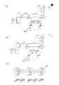
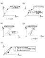
図1は、配電系統100を模式的に示す図である。特に、図1(a)は太陽光発電時における配電系統100を示し、図1(b)は非太陽光発電時における配電系統100を示し、図1(c)は太陽光発電機130の接続形態を例示的に示している。
(Distribution system)
FIG. 1 is a diagram schematically showing a
配電系統100は、三相交流であって、変電所110a、bから送り出された電流を複数の一般家庭140等に供給する。図1(a)、(b)に示すように、一般家庭140等では、太陽光発電時において配電系統100と太陽光発電機130(図1中、PVは太陽光発電(PhotoVoltaic power generation)を表す)の双方から電力が供給され、非太陽光発電時においては必要となる電力が配電系統100のみで賄われる。なお、本実施形態では、太陽光発電機130が発電した電力は一般家庭140等で全て消費されるものと仮定する。
The
図1(c)に示すように、太陽光発電機130は、電灯変圧器132を介して配電系統100における三相(U、V、W)のうち任意の二相に接続する。そのため、太陽光発電機130の発電量に基づき三相交流の不平衡率に影響を与えることとなる。いずれの二相に接続するかは、太陽光発電機130を設置する際に、近隣の接続状況を勘案して決定する。太陽光発電機130の接続形態(接続相と定格発電容量)の情報は、電気事業者において管理する。
As shown in FIG.1 (c), the
配電系統100には、配電区間122ごとに計測機器としてのセンサ内蔵自動開閉器120が設けられている。センサ内蔵自動開閉器120は、線路の開閉(ON/OFF)を行う電子制御式の開閉器であって、さらに電流や電圧、力率等の電気パラメータ計測機能を有している。複数のセンサ内蔵自動開閉器120を制御することにより、配電系統100の経路を切り替えることもできる。
The
よって、例えば事故が発生した場合には、その配電区間122への電力供給を近傍のセンサ内蔵自動開閉器120の経路を切り替えることにより停止することができる。このような場合、事故区間に隣接する区間も一時的に電力が停止してしまうこともあるが、1つの配電区間122には1つの変電所110aからしか電力が供給できないわけではなく、また順送電(通常の送電方向で送電)でしか電力を供給できないわけでもないので、他の変電所110bからの逆送電(通常と逆の送電方向で送電)等により早期に電力が復旧し得る。
Therefore, for example, when an accident occurs, power supply to the
本実施形態において、センサ内蔵自動開閉器120は、計測した電気パラメータのデータを後述する配電系統制御システム200に送信する。詳細には、計測された電流、電圧を、位相情報を含む複素ベクトルに変換して送信する。この変換方法については、当業者にとって周知であり、また特許文献2の段落0050〜0060にも開示されているため、説明を省略する。
In the present embodiment, the sensor built-in
(配電系統制御システム)
図2は、本実施形態にかかる配電系統制御システム200の概略的な構成を示す図である。図2に示すように、配電系統制御システム200は、センサ内蔵自動開閉器120、システム制御部210、入力部212、出力部214、記憶部216、第1演算部218、第2演算部220、第3演算部222、予測部224、切替制御部226を包含する。以下、まずこれらの各要素について説明し、その後本実施形態にかかる配電系統制御システム200が適用する太陽光発電量予測方法、実負荷予測方法について詳細に説明する。
(Distribution system control system)
FIG. 2 is a diagram illustrating a schematic configuration of a power distribution
システム制御部210は、中央処理装置(CPU:Central Processing Unit)を含んで構成されるコンピュータシステムであり、配電系統制御システム200全体を制御する。
The
入力部212は、キーボードやマウス、タッチパネル、またファイル入出力装置やネットワークを通じたデータ通信等により、外部から所定の情報を入力または更新する際に用いられる。例えば、入力部212によって後述する太陽光発電機データテーブル216aに、配電系統100に連系した太陽光発電機130のデータを入力または更新することができる。
The
出力部214は、内部の情報を外部へ出力する役割を担う。出力部214は、例えばディスプレイやプリンタ等で構成され使用者に情報を表示したり、印刷を行ったりする。加えて、出力内容をデータとして記録媒体に保存したり、ネットワークを通じたデータ通信やウェブ表示などを行うことも可能である。
The
記憶部216は、ROM、RAM、EEPROM、不揮発性RAM、フラッシュメモリ、HDD等で構成され、センサ内蔵自動開閉器120が計測した電気パラメータや入力部212によって入力された所定の情報を記憶する。また、記憶部216は、太陽光発電機データテーブル216aを有する。
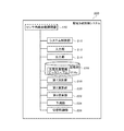
The
図3は、太陽光発電機データテーブル216aの概要を例示する図である。図3に示すように、太陽光発電機データテーブル216aは、配電系統100に連系した太陽光発電機130の各々の接続相、および定格発電容量を記憶している。太陽光発電機データテーブル216aは、例えばハードディスクやCD−ROMなどの記憶媒体で構成することができる。また、太陽光発電機データテーブル216aをデータベースとして随時更新可能なものとして構築すればさらに好適である。
FIG. 3 is a diagram illustrating an outline of the solar power generator data table 216a. As shown in FIG. 3, the solar power generator data table 216 a stores the connection phases and rated power generation capacities of the
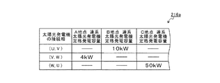
第1演算部218は、太陽光発電機データテーブル216aを参照して、配電系統100の接続相ごと(PWU,PUV,PVW)の総定格発電容量を取得し、各線間の定格発電電流値(IWU,IUV,IVW)を算出する。そして、以下の式1〜式3に基づき線間の定格発電電流を単一相の定格発電電流(IU,IV,IW)を算出する。
IU=IWU−IUV …(式1)
IV=IUV−IVW …(式2)
IW=IVW−IWU …(式3)
The
I U = I WU −I UV (Formula 1)
I V = I UV −I VW (Formula 2)
I W = I VW −I WU (Formula 3)
そして、定格発電電流(IU,IV,IW)を正相電流、逆相電流に変換して、太陽光発電機130の発電を要因とする三相交流の不平衡率が算出される(すなわち、この太陽光発電機130による不平衡率は、机上計算による演算値である)。配電系統100に連系した太陽光発電機130は概して同一に動き(晴天時には、総じて発電量が増加し、曇天時には総じて発電量が減少する)、三相交流のバランスが維持されるためこの不平衡率は常時一定であると考えることができる。なお、ここでの太陽光発電機130の発電を要因とするとは、太陽光発電機130の発電のみに起因するものと解するものとする。
Then, the rated power generation current (I U , I V , I W ) is converted into a normal phase current and a reverse phase current, and the unbalance rate of the three-phase AC caused by the power generation of the
第2演算部220は、記憶部216に格納された配電系統100の予め計測された非太陽光発電時の計測値を参照して、負荷を要因とする三相交流の正相電流および逆相電流の近似関数を導出する。需要家の生活パターンは特殊な電気機器が使用されていなければ総じて一定であり、昼夜問わず線間負荷の傾向を一律と考えることができるため、かかる近似関数を負荷を要因とする正相電流および逆相電流示す関数として太陽光発電時(昼間)にも適用することができる。なお、ここでの負荷を要因とするとは、負荷のみに起因するものと解するものとする。
The
第3演算部222は、センサ内蔵自動開閉器120により計測された予測対象時点における現在値から、配電系統100に連系した太陽光発電機130の発電および負荷を要因とし得る三相交流の正相電流および逆相電流を定める。なお、ここでいう「現在」とは、演算を行っているときとは限らず、負荷(実負荷)または太陽光発電量を知りたいとき(すなわち、予測対象時点)をいい、非太陽光発電時が過去の値であることとの対比において「現在」と表現している。
The
予測部224は、第1演算部218が算出した不平衡率、第2演算部220が導出した近似関数、第3演算部222が定めた予測対象時点の正相電流および逆相電流に基づいて、配電系統100における太陽光発電機130の発電量または実負荷を予測する。すなわち、太陽光発電機130の発電を要因とする予測対象時点における不平衡率(正相電流および逆相電流)の変動を、第1演算部218が算出した不平衡率、第2演算部220が導出した近似関数に基づき解析することにより、かかる不平衡率の媒介変数たる発電量を算出する。なお、太陽光発電機130の発電量または実負荷を予測する方法の具体的な態様については後程詳細に説明する。
The
切替制御部226は、予測部224が予測した発電量または実負荷に基づいて、配電系統100の運用を行う。すなわち、これらの予測値を参照して、配電系統100の経路の切替を行う。これにより、配電系統100の切替を適切に行うことができるため、コストの削減や作業性の向上等様々な効果をもたらすことができる。特に、かかる切替制御部226を配電自動化システムとして構築するとより好適である。
The switching
(太陽光発電量予測方法、実負荷予測方法)
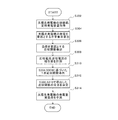
図4は本実施形態にかかる太陽光発電量予測方法、実負荷予測方法を例示するフローチャート、図5は太陽光発電量予測方法、実負荷予測方法を説明する図である。以下、この例示的に示されたフローチャートに則って、太陽光発電機130の発電量または実負荷を予測する態様を具体的に説明する。なお、かかる方法は特定の区間に適用されることが想定され、このような場合には上流側における計測値から下流側における計測値を引いた区間電流を用いるものとする。
(Solar power generation prediction method, actual load prediction method)
FIG. 4 is a flowchart illustrating the photovoltaic power generation amount prediction method and the actual load prediction method according to this embodiment, and FIG. 5 is a diagram illustrating the photovoltaic power generation amount prediction method and the actual load prediction method. Hereinafter, a mode of predicting the power generation amount or the actual load of the
まず事前に、配電系統100に連系した太陽光発電機130の接続形態(接続相と定格発電容量)を取得する(S302)。そして、上述した計算に基づき、太陽光発電機130の発電を要因とする三相交流の不平衡率αを算出する(S304)。この不平衡率αは、いわば太陽光発電機130が発電した場合にどのような軌跡で配電系統100の不平衡率が変動するかを示すものである。
First, the connection form (connection phase and rated power generation capacity) of the
上記過程は、正相電流と逆相電流のグラフ上において、図5(a)のように表される。すなわち、太陽光発電機130の接続相と定格発電容量から求められた正相電流、逆相電流をグラフ上にプロットして0値(原点)から結んだ直線の傾き(比例定数)の逆数となる。
The above process is represented as shown in FIG. 5A on the graph of the positive phase current and the negative phase current. That is, the reciprocal of the slope (proportional constant) of the straight line connected from the zero value (origin) by plotting the positive phase current and the reverse phase current obtained from the connected phase of the
次に、夜間や雨天等の非太陽光発電時におけるセンサ内蔵自動開閉器120の計測値から、配電系統100の負荷を要因とする三相交流の正相電流と逆相電流の分布から近似関数を導出する(S306)。この近似関数が、センサ内蔵自動開閉器120の計測値に当てはまるのは非太陽光発電時のみとなるが、太陽光発電時においても負荷は常に同じ割合で使用されていると想定される。よって、対象を負荷のみとした場合には、常時この式に当てはまると考えられる。
Next, from the measured value of the sensor built-in
上記過程は、正相電流と逆相電流のグラフ上において、図5(b)のように表される。すなわち、S306で導出された近似関数は、グラフ上にプロットしたセンサ内蔵自動開閉器120の計測値に対する近似式となる。なお、図5(b)では、この近似関数は1次関数のように図示した。しかし、本発明はこれに限定するものではなく、いかなる関数(1次関数、2次関数などの多次関数)により導出してもよい。
The above process is represented as shown in FIG. 5B on the graph of the positive phase current and the negative phase current. That is, the approximate function derived in S306 is an approximate expression for the measured value of the sensor built-in
次に、配電系統100の太陽光発電量または実負荷を予測したい時における、センサ内蔵自動開閉器120の正相電流、逆相電流(現在値)を計測する(S308)。そして、この現在値を包含し、S304で算出した不平衡率αの逆数を傾き(比例定数)とする1次近似関数を導出する(S310)。そして、S306で導出した近似関数とS310で導出した1次近似関数の交点を決定する(S312)。
Next, the positive phase current and the reverse phase current (current value) of the sensor built-in
上記過程は、正相電流と逆相電流のグラフ上において、図5(c)、図5(d)のように表される。すなわち、S308における正相電流、逆相電流はプロットIとして表される。そして、S310の1次近似関数は、不平衡率αの逆数を傾きとして、プロットIを通過するように定められる。また、かかる1次近似関数と計測値分布の近似関数との交点が、プロットMとして表される。 The above process is expressed as shown in FIG. 5C and FIG. 5D on the graph of the positive phase current and the negative phase current. That is, the positive phase current and the negative phase current in S308 are expressed as plot I. The linear approximation function of S310 is determined so as to pass through the plot I with the reciprocal of the unbalance rate α as the slope. Further, an intersection point between the linear approximate function and the approximate function of the measured value distribution is represented as a plot M.
すると、プロットIからプロットMまでのベクトルを配電系統100における太陽光発電機130の発電量、0値(原点)からプロットMまでのベクトルを配電系統100の実負荷と予測することができる(S314)。これより、予測された値に基づき配電系統100を適切に運用することが可能となる。
Then, the vector from the plot I to the plot M can be predicted as the power generation amount of the
上記過程は、正相電流と逆相電流のグラフ上において、図5(e)のように表される。すなわち、太陽光発電機130の発電量はプロットIからプロットMまでのベクトルの長さとして、配電系統100における実負荷は0値(原点)からプロットIまでのベクトルの長さとして、配電系統100から供給された電力は0値(原点)からプロットIまでのベクトルの長さとして表される。よって、各々のベクトルの大きさをそれらの電力とみなすことができる。
The above process is represented as shown in FIG. 5E on the graph of the positive phase current and the negative phase current. That is, the power generation amount of the
なお、偶然にもS306で求めた1次近似関数の傾き(不平衡率)とS310で求めた近似関数の傾き(不平衡率)が一致してしまった場合には、ベクトルを定めることができない。このような場合には、予測対象となる区間を拡縮するようにセンサ内蔵自動開閉器120を選択して、予測条件(各近似関数の傾きのいずれかの値)を変動させるとよい。これにより、三相交流のバランスが崩れるため、上述した太陽光発電量予測方法、実負荷予測方法を確実に適用することができる。
If the slope (unbalance rate) of the linear approximation function obtained in S306 coincides with the slope (unbalance rate) of the approximation function obtained in S310, the vector cannot be determined. . In such a case, the sensor built-in
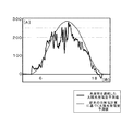
図6は、本実施形態にかかる太陽光発電量予測方法を適用した太陽光発電量の予測値と、従来の日射量計算に基づく太陽光発電量の予測値を比較する図である。図6に示すように、従来の日射量計算に基づく予測方法では、あくまでも平均的な発電量の予測値となり、太陽光発電機130の発電量を詳細に予測できるものではなかった。しかし、本実施形態にかかる太陽光発電量予測方法は、連系した太陽光発電機130の発電(発電量)に起因(媒介)する不平衡率(正相電流、逆相電流)の変動に基づくため、より詳細な予測が可能である。
FIG. 6 is a diagram comparing the predicted value of the photovoltaic power generation amount to which the photovoltaic power generation amount prediction method according to the present embodiment is applied and the predicted value of the photovoltaic power generation amount based on the conventional solar radiation amount calculation. As shown in FIG. 6, in the prediction method based on the conventional solar radiation amount calculation, the average power generation amount is predicted to the last, and the power generation amount of the
以上詳述した構成により、本実施形態によれば、容易に入手可能な最低限のデータから配電系統100ごとの太陽光発電量を天候に依存せずに精度良く予測できる太陽光発電量予測方法および実負荷予測方法、並びにこれらの方法を適用して配電系統100の運用を行う配電系統制御システム200を提供することができる。そのため、最適な配電系統の運用を行うことができ、また過剰な設備投資を回避して最適な設備形成が行えるため、コストの削減効果を奏し得る。さらに、人的作業を低減することにもつながるため、業務の効率改善を図り得る。加えて、供給信頼度の向上、社会への信頼向上といった効果をも奏し得る。
With the configuration described in detail above, according to the present embodiment, the photovoltaic power generation amount prediction method that can accurately predict the photovoltaic power generation amount for each
なお、本実施形態においては、正相電流や逆相電流、不平衡率をセンサ内蔵自動開閉器120によって「計測する」と記載したが、正確にはこれらはセンサ内蔵自動開閉器120が計測した三相交流の電流を変換することにより、算出されるものである。しかし、本実施形態においては、これらの値が計測値の変換により算出されるため、理解を容易にするために「計測する」と表現している。
In the present embodiment, the normal phase current, the reverse phase current, and the unbalance rate are described as “measured” by the sensor built-in
また、上記の実施形態においては、図5において非太陽光発電時の近似関数を1次関数のように図示した。しかし、本発明はこれに限定するものではなく、近似関数は、いかなる関数(1次関数、2次関数などの多次関数)により導出してもよい。 Moreover, in said embodiment, the approximate function at the time of non-solar power generation was illustrated like a linear function in FIG. However, the present invention is not limited to this, and the approximate function may be derived by any function (a multi-order function such as a linear function or a quadratic function).
なお、本発明は係る例に限定されないことは言うまでもない。当業者であれば、特許請求の範囲に記載された範疇内において、各種の変更例または修正例に想到し得ることは明らかであり、それらについても当然に本発明の技術的範囲に属するものと了解される。 Needless to say, the present invention is not limited to such examples. It will be apparent to those skilled in the art that various changes and modifications can be made within the scope of the claims, and these are naturally within the technical scope of the present invention. Understood.
本発明は、太陽光発電機が連系されている配電系統における太陽光発電量予測方法および実負荷予測方法、並びにこれらの方法を適用して配電系統の運用を行う配電系統制御システムに利用することができる。 INDUSTRIAL APPLICABILITY The present invention is used for a photovoltaic power generation amount prediction method and an actual load prediction method in a distribution system in which solar power generators are connected, and a distribution system control system that operates the distribution system by applying these methods. be able to.
100…配電系統、110a、110b…変電所、120…センサ内蔵自動開閉器、122…配電区間、130…太陽光発電機、132…電灯変圧器、140…一般家庭、200…配電系統制御システム、210…システム制御部、212…入力部、214…出力部、216…記憶部、216a…太陽光発電機データテーブル、218…第1演算部、220…第2演算部、222…第3演算部、224…予測部、226…切替制御部
DESCRIPTION OF
Claims (7)
前記配電系統に連系した太陽光発電機の発電を要因とする三相交流の不平衡率を該太陽光発電機の接続形態より算出するステップと、
前記配電系統に連系した前記太陽光発電機の発電がないときの負荷を要因とする三相交流の正相電流と逆相電流との関係式である近似関数を導出するステップと、
前記配電系統の電流を計測して、前記配電系統に連系した前記太陽光発電機の発電および前記負荷を要因とする三相交流の正相電流および逆相電流の予測対象時点における現在値を計測するステップと、
前記不平衡率、前記近似関数、前記現在値に基づいて、前記太陽光発電機の発電量を予測するステップと、
を含むことを特徴とする太陽光発電量予測方法。 A method for predicting the amount of photovoltaic power generation in a distribution system,
Calculating the unbalance rate of the three-phase alternating current caused by the power generation of the solar power generator linked to the power distribution system from the connection form of the solar power generator;
Deriving an approximate function that is a relational expression between the positive and negative phase currents of the three-phase alternating current caused by the load when there is no power generation of the photovoltaic generator linked to the distribution system;
By measuring the current of the distribution system, the current values at the time of prediction of the positive and negative currents of the three-phase alternating current caused by the power generation and load of the photovoltaic generator linked to the distribution system Measuring step,
Predicting the amount of power generated by the photovoltaic generator based on the unbalance rate, the approximate function, and the current value;
A method for predicting the amount of photovoltaic power generation, comprising:
前記現在値を包含し、且つ前記不平衡率から比例定数が定められる1次近似関数を導出するステップと、
前記現在値から前記1次近似関数と前記負荷を要因とする近似関数が交わる値までのベクトルを前記太陽光発電機の発電量として予測するステップと、
を含むことを特徴とする請求項1に記載の太陽光発電量予測方法。 To predict the amount of power generated by the solar generator,
Deriving a first order approximation function that includes the current value and from which the proportionality constant is determined from the unbalance rate;
Predicting a vector from the current value to a value at which the linear approximate function intersects with the approximate function caused by the load as a power generation amount of the photovoltaic generator;
The solar power generation amount prediction method according to claim 1, comprising:
前記配電系統に連系した太陽光発電機の発電を要因とする三相交流の不平衡率を該太陽光発電機の接続形態より算出するステップと、
前記配電系統に連系した前記太陽光発電機の発電がないときの負荷を要因とする三相交流の正相電流と逆相電流との関係式である近似関数を導出するステップと、
前記配電系統の電流を計測して、前記配電系統に連系した前記太陽光発電機の発電および前記負荷を要因とする三相交流の正相電流および逆相電流の予測対象時点における現在値を計測するステップと、
前記不平衡率、前記近似関数、前記現在値に基づいて、前記配電系統の実負荷を予測するステップと、
を含むことを特徴とする実負荷予測方法。 An actual load prediction method in a distribution system,
Calculating the unbalance rate of the three-phase alternating current caused by the power generation of the solar power generator linked to the power distribution system from the connection form of the solar power generator;
Deriving an approximate function that is a relational expression between the positive and negative phase currents of the three-phase alternating current caused by the load when there is no power generation of the photovoltaic generator linked to the distribution system;
By measuring the current of the distribution system, the current values at the time of prediction of the positive and negative currents of the three-phase alternating current caused by the power generation and load of the photovoltaic generator linked to the distribution system Measuring step,
Predicting the actual load of the distribution system based on the unbalance rate, the approximation function, and the current value;
The actual load prediction method characterized by including.
前記現在値を包含し、且つ前記不平衡率から比例定数が定められる1次近似関数を導出するステップと、
0値から前記1次近似関数と前記負荷を要因とする近似関数が交わる値までのベクトルを実負荷として予測するステップと、
を含むことを特徴とする請求項5に記載の実負荷予測方法。 To predict the actual load of the distribution system,
Deriving a first order approximation function that includes the current value and from which the proportionality constant is determined from the unbalance rate;
Predicting, as an actual load, a vector from a zero value to a value at which the first order approximation function and the approximation function caused by the load
The actual load prediction method according to claim 5, further comprising:
前記配電系統に連系した太陽光発電機のデータを含む所定の情報を入力または更新可能な入力部と、
前記計測機器の計測値や前記所定の情報を記憶する記憶部と、
前記データから前記太陽光発電機の接続相ごとの総定格発電容量を求め、前記配電系統に連系した該太陽光発電機の発電を要因とする三相交流の不平衡率を算出する第1演算部と、
予め計測された前記計測値を参照して、前記配電系統に連系した前記太陽光発電機の発電がないときの負荷を要因とする三相交流の正相電流と逆相電流との関係式である近似関数を導出する第2演算部と、
前記計測機器により計測された予測対象時点における現在値を参照して、前記配電系統に連系した前記太陽光発電機の発電および前記負荷を要因とする三相交流の正相電流および逆相電流を定める第3演算部と、
前記第1演算部が算出した前記不平衡率、前記第2演算部が導出した前記近似関数、前記第3演算部が定めた前記正相電流および前記逆相電流に基づいて、前記太陽光発電機の発電量または前記配電系統の実負荷を予測する予測部と、
前記予測部が予測した前記発電量または前記実負荷に基づいて、前記配電系統の運用を行う切替制御部と、
を備えることを特徴とする配電系統制御システム。 A measuring device that measures the current of the power distribution system;
An input unit capable of inputting or updating predetermined information including data of a solar power generator linked to the distribution system;
A storage unit for storing measurement values of the measuring device and the predetermined information;
First, a total rated power generation capacity for each connected phase of the solar power generator is determined from the data, and a three-phase AC unbalance rate caused by power generation of the solar power generator linked to the distribution system is calculated. An arithmetic unit;
Referring to the measurement value measured in advance , a relational expression between the positive and negative phase currents of the three-phase alternating current caused by the load when there is no power generation of the photovoltaic generator linked to the distribution system A second computing unit for deriving an approximate function that is
With reference to the current value at the prediction target time measured by the measuring device, the positive-phase current and the negative-phase current of the three-phase alternating current caused by the power generation of the photovoltaic generator and the load connected to the power distribution system A third arithmetic unit for determining
Based on the unbalance rate calculated by the first calculation unit, the approximate function derived by the second calculation unit, the positive phase current and the negative phase current determined by the third calculation unit, the solar power generation A prediction unit for predicting the power generation amount of the machine or the actual load of the distribution system
Based on the power generation amount or the actual load predicted by the prediction unit, a switching control unit that operates the distribution system,
A distribution system control system comprising:
Priority Applications (1)
| Application Number | Priority Date | Filing Date | Title |
|---|---|---|---|
| JP2009185543A JP5476848B2 (en) | 2009-08-10 | 2009-08-10 | Photovoltaic power generation amount prediction method, actual load prediction method, and distribution system control system |
Applications Claiming Priority (1)
| Application Number | Priority Date | Filing Date | Title |
|---|---|---|---|
| JP2009185543A JP5476848B2 (en) | 2009-08-10 | 2009-08-10 | Photovoltaic power generation amount prediction method, actual load prediction method, and distribution system control system |
Publications (2)
| Publication Number | Publication Date |
|---|---|
| JP2011041384A JP2011041384A (en) | 2011-02-24 |
| JP5476848B2 true JP5476848B2 (en) | 2014-04-23 |
Family
ID=43768547
Family Applications (1)
| Application Number | Title | Priority Date | Filing Date |
|---|---|---|---|
| JP2009185543A Active JP5476848B2 (en) | 2009-08-10 | 2009-08-10 | Photovoltaic power generation amount prediction method, actual load prediction method, and distribution system control system |
Country Status (1)
| Country | Link |
|---|---|
| JP (1) | JP5476848B2 (en) |
Cited By (1)
| Publication number | Priority date | Publication date | Assignee | Title |
|---|---|---|---|---|
| CN105512379A (en) * | 2015-12-02 | 2016-04-20 | 国家电网公司 | Comprehensive assessment method for photovoltaic power station inverter |
Families Citing this family (3)
| Publication number | Priority date | Publication date | Assignee | Title |
|---|---|---|---|---|
| JP5477038B2 (en) * | 2010-02-19 | 2014-04-23 | 東京電力株式会社 | Photovoltaic power generation amount prediction method and distribution system control system |
| FR2983363B1 (en) * | 2011-11-28 | 2014-07-25 | Schneider Electric Ind Sas | METHOD AND SYSTEM FOR DYNAMICALLY MANAGING AN ELECTRICITY DISTRIBUTION NETWORK |
| CN116523148B (en) * | 2023-07-03 | 2023-09-22 | 广东电网有限责任公司湛江供电局 | Distribution network distribution transformer overload early warning method, device and equipment |
Family Cites Families (3)
| Publication number | Priority date | Publication date | Assignee | Title |
|---|---|---|---|---|
| JP4576315B2 (en) * | 2005-10-13 | 2010-11-04 | 関西電力株式会社 | Method and program for detecting linked generators |
| JP5239657B2 (en) * | 2008-09-09 | 2013-07-17 | 東京電力株式会社 | Load amount estimation method, load curve derivation method, load curve derivation device, and load amount estimation device |
| JP5442282B2 (en) * | 2009-03-12 | 2014-03-12 | 株式会社日立製作所 | Method and apparatus for estimating generator output |
-
2009
- 2009-08-10 JP JP2009185543A patent/JP5476848B2/en active Active
Cited By (1)
| Publication number | Priority date | Publication date | Assignee | Title |
|---|---|---|---|---|
| CN105512379A (en) * | 2015-12-02 | 2016-04-20 | 国家电网公司 | Comprehensive assessment method for photovoltaic power station inverter |
Also Published As
| Publication number | Publication date |
|---|---|
| JP2011041384A (en) | 2011-02-24 |
Similar Documents
| Publication | Publication Date | Title |
|---|---|---|
| JP6444286B2 (en) | How to configure the power distribution system | |
| CN103620903B (en) | Electric power supply system | |
| Ceran | The concept of use of PV/WT/FC hybrid power generation system for smoothing the energy profile of the consumer | |
| Østergaard | Regulation strategies of cogeneration of heat and power (CHP) plants and electricity transit in Denmark | |
| JP2015080401A (en) | Methods and systems for controlling electric network | |
| EP2660943A1 (en) | Power controller | |
| WO2014045656A1 (en) | System control device and system control method | |
| KR101516802B1 (en) | A Distribution panel for a stand-alone micro-grid | |
| CN105556779A (en) | Apparatus and method for providing power interface | |
| JP5505191B2 (en) | Photovoltaic power generation amount prediction method and distribution system control system | |
| Shahmohammadi et al. | Proper sizing and placement of distributed power generation aids the intentional islanding process | |
| JP2010193594A (en) | Maximum power generation amount estimating method for photovoltaic power generation system, method for controlling power distribution system, and distribution system control apparatus | |
| JP2010193605A (en) | Load estimating method of power distribution section and power distribution system control method | |
| JP5476848B2 (en) | Photovoltaic power generation amount prediction method, actual load prediction method, and distribution system control system | |
| JP5556289B2 (en) | Distributed power supply and distributed power supply control method | |
| JP5477038B2 (en) | Photovoltaic power generation amount prediction method and distribution system control system | |
| WO2020218191A1 (en) | Power control device, method of controlling power control device, and distributed power generation system | |
| JPWO2014167830A1 (en) | Power control system | |
| Yoshizawa et al. | Advanced voltage control based on short-time ahead voltage fluctuation estimation in distribution system | |
| Amraee et al. | System protection scheme for mitigation of cascaded voltage collapses | |
| Suslov et al. | Expansion planning of active power supply systems | |
| JP2019193479A (en) | Power storage battery control device and power storage battery control program | |
| JP2017127129A (en) | Storage battery control method | |
| JP2011135644A (en) | Dead zone avoidance system, dead zone avoiding device, and method of avoiding dead zone | |
| JP6696235B2 (en) | Power distribution control system and prediction program |
Legal Events
| Date | Code | Title | Description |
|---|---|---|---|
| A621 | Written request for application examination |
Free format text: JAPANESE INTERMEDIATE CODE: A621 Effective date: 20120806 |
|
| A131 | Notification of reasons for refusal |
Free format text: JAPANESE INTERMEDIATE CODE: A131 Effective date: 20130917 |
|
| A521 | Request for written amendment filed |
Free format text: JAPANESE INTERMEDIATE CODE: A523 Effective date: 20131010 |
|
| TRDD | Decision of grant or rejection written | ||
| A01 | Written decision to grant a patent or to grant a registration (utility model) |
Free format text: JAPANESE INTERMEDIATE CODE: A01 Effective date: 20140114 |
|
| A61 | First payment of annual fees (during grant procedure) |
Free format text: JAPANESE INTERMEDIATE CODE: A61 Effective date: 20140127 |
|
| R150 | Certificate of patent or registration of utility model |
Ref document number: 5476848 Country of ref document: JP Free format text: JAPANESE INTERMEDIATE CODE: R150 |
|
| S533 | Written request for registration of change of name |
Free format text: JAPANESE INTERMEDIATE CODE: R313533 |
|
| R350 | Written notification of registration of transfer |
Free format text: JAPANESE INTERMEDIATE CODE: R350 |